EP1391279A2 - Apparatus for making webs - Google Patents
Apparatus for making webs Download PDFInfo
- Publication number
- EP1391279A2 EP1391279A2 EP03014083A EP03014083A EP1391279A2 EP 1391279 A2 EP1391279 A2 EP 1391279A2 EP 03014083 A EP03014083 A EP 03014083A EP 03014083 A EP03014083 A EP 03014083A EP 1391279 A2 EP1391279 A2 EP 1391279A2
- Authority
- EP
- European Patent Office
- Prior art keywords
- roller
- press
- deflection
- press nip
- yoke
- Prior art date
- Legal status (The legal status is an assumption and is not a legal conclusion. Google has not performed a legal analysis and makes no representation as to the accuracy of the status listed.)
- Granted
Links
- 238000004519 manufacturing process Methods 0.000 claims abstract description 14
- 239000000463 material Substances 0.000 claims abstract description 7
- 229910000831 Steel Inorganic materials 0.000 claims description 9
- 239000010959 steel Substances 0.000 claims description 9
- 239000000123 paper Substances 0.000 claims description 8
- 239000000835 fiber Substances 0.000 claims description 7
- 239000011093 chipboard Substances 0.000 claims description 6
- 239000002245 particle Substances 0.000 claims description 5
- 239000011230 binding agent Substances 0.000 claims description 4
- 239000011094 fiberboard Substances 0.000 claims description 4
- 229920001187 thermosetting polymer Polymers 0.000 claims description 2
- 238000010438 heat treatment Methods 0.000 description 2
- 230000006978 adaptation Effects 0.000 description 1
- 229920002678 cellulose Polymers 0.000 description 1
- 239000001913 cellulose Substances 0.000 description 1
- 230000006835 compression Effects 0.000 description 1
- 238000007906 compression Methods 0.000 description 1
- 239000003292 glue Substances 0.000 description 1
- 230000001939 inductive effect Effects 0.000 description 1
- 230000000149 penetrating effect Effects 0.000 description 1
- 230000002093 peripheral effect Effects 0.000 description 1
- 239000007858 starting material Substances 0.000 description 1
Images

Classifications
-
- D—TEXTILES; PAPER
- D21—PAPER-MAKING; PRODUCTION OF CELLULOSE
- D21F—PAPER-MAKING MACHINES; METHODS OF PRODUCING PAPER THEREON
- D21F3/00—Press section of machines for making continuous webs of paper
- D21F3/02—Wet presses
- D21F3/04—Arrangements thereof
- D21F3/045—Arrangements thereof including at least one extended press nip
-
- B—PERFORMING OPERATIONS; TRANSPORTING
- B27—WORKING OR PRESERVING WOOD OR SIMILAR MATERIAL; NAILING OR STAPLING MACHINES IN GENERAL
- B27N—MANUFACTURE BY DRY PROCESSES OF ARTICLES, WITH OR WITHOUT ORGANIC BINDING AGENTS, MADE FROM PARTICLES OR FIBRES CONSISTING OF WOOD OR OTHER LIGNOCELLULOSIC OR LIKE ORGANIC MATERIAL
- B27N3/00—Manufacture of substantially flat articles, e.g. boards, from particles or fibres
- B27N3/08—Moulding or pressing
- B27N3/26—Moulding or pressing characterised by using continuously acting presses having a heated press drum and an endless belt to compress the material between belt and drum
-
- B—PERFORMING OPERATIONS; TRANSPORTING
- B30—PRESSES
- B30B—PRESSES IN GENERAL
- B30B3/00—Presses characterised by the use of rotary pressing members, e.g. rollers, rings, discs
- B30B3/005—Roll constructions
-
- B—PERFORMING OPERATIONS; TRANSPORTING
- B30—PRESSES
- B30B—PRESSES IN GENERAL
- B30B5/00—Presses characterised by the use of pressing means other than those mentioned in the preceding groups
- B30B5/04—Presses characterised by the use of pressing means other than those mentioned in the preceding groups wherein the pressing means is in the form of an endless band
-
- D—TEXTILES; PAPER
- D21—PAPER-MAKING; PRODUCTION OF CELLULOSE
- D21F—PAPER-MAKING MACHINES; METHODS OF PRODUCING PAPER THEREON
- D21F3/00—Press section of machines for making continuous webs of paper
- D21F3/02—Wet presses
- D21F3/0209—Wet presses with extended press nip
-
- D—TEXTILES; PAPER
- D21—PAPER-MAKING; PRODUCTION OF CELLULOSE
- D21G—CALENDERS; ACCESSORIES FOR PAPER-MAKING MACHINES
- D21G1/00—Calenders; Smoothing apparatus
- D21G1/02—Rolls; Their bearings
- D21G1/0206—Controlled deflection rolls
- D21G1/0213—Controlled deflection rolls with deflection compensation means acting between the roller shell and its supporting member
- D21G1/022—Controlled deflection rolls with deflection compensation means acting between the roller shell and its supporting member the means using fluid pressure
Definitions
- the invention relates to a device for producing webs of material with a rotating, with a moving counter surface a press nip forming press belt and with several on top of each other in the direction of web travel following deflection adjustment rollers, through which the rotating Press belt in the press nip area against the moving counter surface is pressable, the deflection adjustment rollers each rotating Roller jacket, a non-rotatable penetrating the roller jacket Yoke and pressure elements arranged between the roll shell and the yoke include that on the yoke side facing the press nip are provided and via which the roller shell in the direction of Press nip is acted upon.
- At least one Part of the deflection adjustment rollers each with at least one between the roller shell and the yoke arranged counter element is provided, which is provided on the yoke side facing away from the press nip and through which the roller jacket in one direction away from the press nip is acted upon.
- a respective deflection adjustment roller can also be on the primary side in particular again with several pressure elements distributed across the roller width be provided, in particular individually or in groups can be controlled separately.
- Those in the edge zones of a respective deflection adjustment roller 22 provided counter-elements 30 can, for example, depending can be controlled or deactivated by the respective web width.
- the deflection adjustment rollers 22 can, for example, have an in the roll surface 24, which is adjustable relative to the yoke 26, i.e. be provided as so-called self-adjusting rollers. In in this case, the jacket 24 of the respective deflection adjustment roller 22 can be locked in its position raised from the counter surface 16.
Landscapes
- Engineering & Computer Science (AREA)
- Life Sciences & Earth Sciences (AREA)
- Mechanical Engineering (AREA)
- Manufacturing & Machinery (AREA)
- Wood Science & Technology (AREA)
- Forests & Forestry (AREA)
- Physics & Mathematics (AREA)
- Fluid Mechanics (AREA)
- Dry Formation Of Fiberboard And The Like (AREA)
- Folding Of Thin Sheet-Like Materials, Special Discharging Devices, And Others (AREA)
Abstract
Eine Vorrichtung zur Herstellung von Materialbahnen (12) umfasst ein umlaufendes,
mit einer bewegten Gegenfläche einen Pressspalt (20) bildendes Pressband (14)
sowie mehrere in Bahnlaufrichtung aufeinanderfolgende Durchbiegungseinstellwalzen (22),
durch die das umlaufende Pressband (14) im Pressspaltbereich
gegen die bewegte Gegenfläche pressbar ist, wobei die Durchbiegungseinstellwalzen (22)
jeweils einen umlaufenden Walzenmantel (24), ein den
Walzenmantel (24) durchsetzendes drehfestes Joch sowie zwischen dem Walzenmantel (24)
und dem Joch angeordnete Anpresselemente (28) umfassen, die auf
der dem Pressspalt (20) zugewandten Jochseite vorgesehen sind und über die
der Walzenmantel (24) in Richtung des Pressspalts (20) beaufschlagbar ist. Dabei
ist zumindest ein Teil der Durchbiegungseinstellwalzen (22) jeweils mit wenigstens
einem zwischen dem Walzenmantel (24) und dem Joch angeordneten
Gegenelement versehen, das auf der vom Pressspalt (20) abgewandten Jochseite
vorgesehen und über das der Walzenmantel (24) in einer Richtung vom
Pressspalt (20) weg beaufschlagbar ist.
Description
Die Erfindung betrifft eine Vorrichtung zur Herstellung von Materialbahnen mit einem umlaufenden, mit einer bewegten Gegenfläche einen Pressspalt bildenden Pressband sowie mit mehreren in Bahnlaufrichtung aufeinander folgenden Durchbiegungseinstellwalzen, durch die das umlaufende Pressband im Pressspaltbereich gegen die bewegte Gegenfläche pressbar ist, wobei die Durchbiegungseinstellwalzen jeweils einen umlaufenden Walzenmantel, ein den Walzenmantel durchsetzendes drehfestes Joch sowie zwischen dem Walzenmantel und dem Joch angeordnete Anpresselemente umfassen, die auf der dem Pressspalt zugewandten Jochseite vorgesehen sind und über die der Walzenmantel in Richtung des Pressspaltes beaufschlagbar ist.The invention relates to a device for producing webs of material with a rotating, with a moving counter surface a press nip forming press belt and with several on top of each other in the direction of web travel following deflection adjustment rollers, through which the rotating Press belt in the press nip area against the moving counter surface is pressable, the deflection adjustment rollers each rotating Roller jacket, a non-rotatable penetrating the roller jacket Yoke and pressure elements arranged between the roll shell and the yoke include that on the yoke side facing the press nip are provided and via which the roller shell in the direction of Press nip is acted upon.
Im Bereich der Faser- und Spanplattenherstellung wird üblicherweise eine mit 6 bis 22 % Leim versehene Span- oder Fasermenge zwischen einer beheizten Trommel und einem umlaufenden Stahlband zu Platten verdichtet. Der Durchmesser der Trommel liegt üblicherweise in einem Bereich von 2 bis 5 m. Die erhaltenen Platten besitzen in üblicher Weise eine Dicke in einem Bereich von 1,5 bis 12 mm. Das ebenfalls heiße Stahlband wird durch wenigstens eine Walze (vgl. z.B. DE 42 43 917 C) gegen die Trommel gepresst. Bei älteren Vorrichtungen der genannten Art weisen die Walzen einen relativ großen gegenseitigen Abstand auf. Im Bereich zwischen den relativ weit voneinander entfernten Walzen ergibt sich durch die Bandzugspannung nun aber lediglich ein relativ geringer Anpressdruck auf den Faserkuchen, der beispielsweise in einem Bereich von 20 bis 25 N/cm2 liegen kann. Demgegenüber kann die Linienlast zwischen einer relativ harten Walze und der Trommel beispielsweise 10 000 N/cm betragen. Bei einer aus der EP 0 776 742 B bekannten Vorrichtung der genannten Art liegen die Durchbiegungseinstellwalzen in Bahnlaufrichtung nun dichter hintereinander, wodurch einerseits der zeitliche Abstand der Kraftpeaks auf den Faserkuchen reduziert und andererseits der Anpressdruck auf den Faserkuchen zwischen den Kraftpeaks auf einem höheren Niveau gehalten wird. Zur Optimierung des Systems wurde bisher also nur der Weg beschritten, relativ wenige große Druckwalzen mit einem Durchmesser von beispielsweise etwa 1,5 m durch mehrere direkt hintereinander liegende kleinere Durchbiegungseinstellwalzen mit einem Durchmesser von beispielsweise etwa 0,32 m zu ersetzen.In the field of fiber and particle board production, a quantity of chip or fiber provided with 6 to 22% glue is usually compressed into plates between a heated drum and a rotating steel belt. The diameter of the drum is usually in a range from 2 to 5 m. The plates obtained usually have a thickness in a range from 1.5 to 12 mm. The steel strip, which is also hot, is pressed against the drum by at least one roller (cf., for example, DE 42 43 917 C). In older devices of the type mentioned, the rollers are at a relatively large mutual distance. In the area between the rollers, which are relatively far apart from one another, the tape tension now results in only a relatively low contact pressure on the fiber cake, which can be, for example, in a range from 20 to 25 N / cm 2 . In contrast, the line load between a relatively hard roller and the drum can be, for example, 10,000 N / cm. In a device of the type mentioned, which is known from EP 0 776 742 B, the deflection adjustment rollers are now closer behind one another in the web running direction, which on the one hand reduces the time interval between the force peaks on the fiber cake and on the other hand keeps the contact pressure on the fiber cake between the force peaks at a higher level , To optimize the system, the only way to go so far has been to replace relatively few large pressure rollers with a diameter of, for example, about 1.5 m by several smaller deflection adjustment rollers with a diameter of, for example, about 0.32 m, which are located directly one behind the other.
Der Erfindung liegt die Aufgabe zugrunde, die Vorrichtung der eingangs genannten Art weiter zu optimieren.The invention has for its object the device of the beginning to further optimize the type mentioned.
Dabei soll u.a. ein möglichst großes Einstellpotential bezüglich des Pressdrucks im Pressspalt erreicht werden.Among other things, the greatest possible setting potential with regard to the pressing pressure can be reached in the press nip.
Diese Aufgabe wird erfindungsgemäß dadurch gelöst, dass zumindest ein Teil der Durchbiegungseinstellwalzen jeweils mit wenigstens einem zwischen dem Walzenmantel und dem Joch angeordneten Gegenelement versehen ist, das auf der vom Pressspalt abgewandten Jochseite vorgesehen und über das der Walzenmantel in einer Richtung vom Pressspalt weg beaufschlagbar ist. This object is achieved in that at least one Part of the deflection adjustment rollers each with at least one between the roller shell and the yoke arranged counter element is provided, which is provided on the yoke side facing away from the press nip and through which the roller jacket in one direction away from the press nip is acted upon.
Aufgrund dieser Ausbildung wird das Einstellpotential hinsichtlich des im Pressspalt erzeugten Pressdrucks entsprechend vergrößert. So sind mit einer sowohl Primär- als auch Sekundärzonen aufweisenden Durchbiegungseinstellwalze insbesondere auch kleinere Pressdrücke möglich. Dabei ist die jeweilige Presskraft, mit der der Walzenmantel gegen die bewegte Gegenfläche gepresst wird, durch die Differenz der durch die Primär- und Sekundärelemente erzeugten Kräfte bestimmt.Because of this training, the potential for adjustment in terms of Press nip generated press pressure increased accordingly. So are with a deflection adjustment roller having both primary and secondary zones in particular, smaller pressing pressures are also possible. The respective pressing force with which the roll shell acts against the moving counter surface is pressed by the difference of the Forces generated by primary and secondary elements.
Vorteilhafterweise ist zumindest in den Randzonen einer jeweiligen Durchbiegungseinstellwalze jeweils wenigstens ein Gegenelement vorgesehen. Mit einer entsprechenden Ansteuerung der in den Randzonen vorgesehenen Gegenelementen kann der primärseitige Druck entlastet werden, so dass z.B. durch eine entsprechende Randabschaltung eine Anpassung an unterschiedliche Bahnbreiten möglich ist.It is advantageous at least in the edge zones of a respective deflection adjustment roller each provided at least one counter element. With a corresponding control of those provided in the peripheral zones Counter elements can be relieved of pressure on the primary side, so that e.g. an adaptation to this by a corresponding edge shutdown different web widths is possible.
Bevorzugt ist eine jeweilige Durchbiegungseinstellwalze mit mehreren über die Walzenbreite verteilten Gegenelementen versehen.A respective deflection adjustment roller with several over is preferred the roller width distributed counter elements.
Die Gegenelemente einer jeweiligen Durchbiegungseinstellwalze können zumindest teilweise getrennt ansteuerbar sein. Dabei können diese Gegenelemente einzeln oder auch gruppenweise getrennt voneinander ansteuerbar sein.The counter elements of a respective deflection adjustment roller can be at least partially controllable separately. These counter elements can can be controlled individually or in groups separately his.
Auch primärseitig kann eine jeweilige Durchbiegungseinstellwalze insbesondere wieder mit mehreren über die Walzenbreite verteilten Anpresselementen versehen sein, die insbesondere wieder einzeln oder gruppenweise getrennt ansteuerbar sind. A respective deflection adjustment roller can also be on the primary side in particular again with several pressure elements distributed across the roller width be provided, in particular individually or in groups can be controlled separately.
In bestimmten Fällen kann es von Vorteil sein, wenn jedem Anpresselement einer jeweiligen Durchbiegungseinstellwalze jeweils ein Gegenelement gegenüberliegt.In certain cases it can be an advantage if each pressure element a counter element for each deflection adjustment roller opposite.
Vorteilhafterweise sind in den Randzonen einer jeweiligen Durchbiegungseinstellwalze Anpresselemente in Abhängigkeit von der jeweiligen Bahnbreite ansteuerbar bzw. deaktivierbar.Advantageously, in the edge zones of a respective deflection adjustment roller Pressure elements depending on the respective web width can be controlled or deactivated.
Wie bereits erwähnt, können in den Randzonen einer jeweiligen Durchbiegungseinstellwalze vorgesehene Gegenelemente insbesondere in Abhängigkeit von der jeweiligen Bahnbreite ansteuerbar bzw. deaktivierbar sein.As already mentioned, in the edge zones of a respective deflection adjustment roller provided counter elements in particular depending can be controlled or deactivated by the respective web width.
Bei einer bevorzugten praktischen Ausführungsform der erfindungsgemäßen Vorrichtung ist wenigstens eine Durchbiegungseinstellwalze mit einem in der Pressebene relativ zum Joch verstellbaren Walzenmantel versehen. Der Mantel einer solchen Durchbiegungseinstellwalze ist in seiner von der Gegenfläche abgehobenen Position vorzugsweise arretierbar.In a preferred practical embodiment of the invention The device has at least one deflection adjustment roller a roller jacket that is adjustable relative to the yoke in the press plane Mistake. The jacket of such a deflection adjustment roller is in its position raised from the counter surface can preferably be locked.
Der zwischen dem umlaufenden Pressband und der bewegten Gegenfläche gebildete Pressspalt kann einseitig oder beidseitig beheizbar sein.The one between the rotating press belt and the moving counter surface Press nip formed can be heated on one or both sides.
Der Pressspalt besitzt vorzugsweise einen gekrümmten Verlauf. Die bewegte Gegenfläche kann insbesondere durch eine umlaufende Presstrommel gebildet sein.The press nip preferably has a curved course. The moving Counter surface can in particular by a rotating press drum be educated.
Vorteilhafterweise ist das Pressband zumindest im Eingangsbereich und Ausgangsbereich des Pressspaltes jeweils über eine Umlenkwalze geführt. The press belt is advantageously at least in the entrance area and The exit area of the press nip is each guided over a deflection roller.
Dabei ist das Pressband vorzugsweise nur im Eingangsbereich und Ausgangsbereich des Pressspaltes über eine jeweilige Umlenkwalze geführt, während zumindest ein Teil der Durchbiegungseinstellwalzen auch auf der vom Pressspalt abgewandten Seite der Pressbandführung dient. Es ist also insbesondere eine solche Ausführung denkbar, bei der das Pressband über die im Eingangsbereich des Pressspaltes angeordnete Umlenkwalze, über die bewegte Gegenfläche, gegen die es durch die Durchbiegungseinstellwalzen pressbar ist, die im Ausgangsbereich des Pressspaltes angeordnete Umlenkwalze und über die vom Pressspalt abgewandte Seite zumindest eines Teils der Durchbiegungseinstellwalzen zurück zur im Eingangsbereich des Pressspaltes angeordneten Umlenkwalze geführt ist. Das Pressband wird also nur über zwei im Eingangs- bzw. Ausgangsbereich der Materialverdichtungsstrecke vorgesehene Umlenkwalzen und im übrigen nur über die zweiseitig als Führung dienende Durchbiegungseinstellwalzen geführt. In diesem Fall ist eine zweiseitige Belastungsmöglichkeit erforderlich.The press belt is preferably only in the entrance area and exit area the press nip is guided over a respective deflection roller, while at least part of the deflection adjustment rollers also on the side of the press belt guide facing away from the press nip. So it is in particular, such an embodiment is conceivable in which the press belt via the deflection roller arranged in the entrance area of the press nip, over the moving counter surface against which it is set by the deflection adjustment rollers can be pressed, the one arranged in the exit region of the press nip Deflection roller and over the side facing away from the press nip at least part of the deflection adjustment rollers back to the im Entrance area of the press nip arranged deflection roller is guided. The press belt is therefore only over two in the entrance and exit area the material compression section provided deflection rollers and the rest only via the deflection adjustment rollers serving as guides on both sides guided. In this case, there is a two-sided burden required.
Das umlaufende Pressband kann vorteilhafterweise durch ein Stahlband gebildet sein.The rotating press belt can advantageously be made by a steel belt be educated.
Auch das umlaufende Pressband bzw. Stahlband ist vorzugsweise wieder beheizbar. Grundsätzlich können auch die Durchbiegungseinstellwalzen zumindest teilweise beheizbar sein.The rotating press belt or steel belt is also preferably again heated. In principle, the deflection adjustment rollers can also be used be at least partially heatable.
Bei einer bevorzugten praktischen Ausführungsform der erfindungsgemäßen Vorrichtung sind die in Bahnlaufrichtung aufeinanderfolgenden Durchbiegungseinstellwalzen zumindest teilweise dicht hintereinander angeordnet. Dabei können die Durchbiegungseinstellwalzen beispielsweise auch zu Gruppen zusammengefasst sein. Innerhalb der jeweiligen Gruppen sind die Durchbiegungseinstellwalzen dann jeweils möglichst dicht aufeinanderfolgend angeordnet, während zwischen zwei jeweiligen Gruppen ggf. auch ein relativ größerer Abstand vorgesehen sein kann.In a preferred practical embodiment of the invention The devices are successive in the web running direction Deflection adjusting rollers at least partially closely behind one another arranged. The deflection adjustment rollers can, for example also be grouped together. Within the respective groups the deflection adjustment rollers are then each as tight as possible arranged sequentially while between two respective groups if necessary, a relatively larger distance can also be provided.
Die erfindungsgemäße Vorrichtung ist vorteilhafterweise insbesondere anwendbar zur Herstellung von in einzelne Platten aufteilbaren Faserplattenbahnen, Spanplattenbahnen und/oder dergleichen aus einem lignozellulose- und/oder zellulosehaltige Teilchen und zumindest ein Bindemittel enthaltenden Vlies.The device according to the invention is advantageously in particular applicable for the production of fiberboard webs that can be divided into individual panels, Chipboard sheets and / or the like made of a lignocellulosic and / or cellulose-containing particles and at least one binder containing fleece.
Die erfindungsgemäße Vorrichtung ist vorteilhafterweise insbesondere zur Herstellung von Faserstoff-, Span-, HDF-, MDF-, LDF- und/oder OSB-Platten verwendbar.The device according to the invention is advantageously particularly for Manufacture of fiber, chipboard, HDF, MDF, LDF and / or OSB boards usable.
Grundsätzlich ist die erfindungsgemäße Vorrichtung beispielsweise auch in einer Papiermaschine, einem Kalander, einer Druckmaschine oder einer Vorrichtung zur Herstellung von Dekorpapier verwendbar.Basically, the device according to the invention is also, for example in a paper machine, a calender, a printing machine or one Device for the production of decorative paper can be used.
Beliebige andere Verwendungen sind denkbar.Any other uses are conceivable.
Die Erfindung wird im folgenden anhand eines Ausführungsbeispiels unter Bezugnahme auf die Zeichnung näher erläutert; in dieser zeigen:
- Figur 1
- eine schematische Darstellung einer Vorrichtung zur Herstellung von Materialbahnen und
- Figur 2
- eine schematische Längsschnittdarstellung einer in der Vorrichtung gemäß Figur 1 eingesetzten Durchbiegungseinstellwalze.
- Figure 1
- is a schematic representation of an apparatus for producing webs of material and
- Figure 2
- is a schematic longitudinal sectional view of a deflection adjusting roller used in the device according to Figure 1.
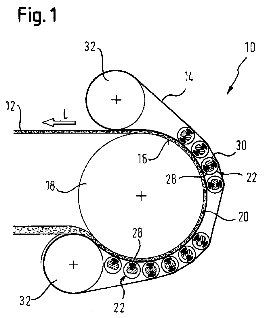
Die Figur 1 zeigt in rein schematischer Darstellung eine Vorrichtung 10
zur Herstellung von Materialbahnen 12, bei denen es sich beispielsweise
um in einzelne Platten aufteilbare Faserplattenbahnen, Spanplattenbahnen
und/oder dergleichen aus einem lignozellulose- und/oder zellulosehaltige
Teilchen und zumindest ein Bindemittel enthaltenden Vlies handeln
kann. Die Vorrichtung 10 ist beispielsweise auch zur Herstellung von
HDF-, MDF-, LDF- und/oder OSB-Platten verwendbar. Generell ist beispielsweise
auch eine Verwendung in einer Papiermaschine, einem Kalander,
einer Druckmaschine oder einer Maschine zur Herstellung von Dekorpapier
denkbar.FIG. 1 shows a
Die Vorrichtung 10 umfasst ein beispielsweise durch ein Stahlband gebildetes
umlaufendes Pressband 14, das mit einer bewegten Gegenfläche 16,
die hier beispielsweise durch die Oberfläche einer Presstrommel 18 gebildet
ist, einen Pressspalt 20 definiert, in dem das zur Herstellung der
Materialbahn 12 dienende Ausgangsmaterial verdichtet wird.The
Die Vorrichtung 10 umfasst überdies eine Mehrzahl von in Bahnlaufrichtung
L aufeinanderfolgenden Durchbiegungseinstellwalzen 22, durch die
das umlaufende Pressband 14 im Bereich des Pressspaltes 20 gegen die
bewegte Gegenfläche 16, hier also gegen die Presstrommel 18 pressbar ist.The
Wie insbesondere auch anhand der Figur 2 zu erkennen ist, umfassen die
Durchbiegungseinstellwalzen 22 jeweils einen umlaufenden Walzenmantel
24, ein den Walzenmantel 24 durchsetzendes drehfestes Joch 26 sowie
zwischen dem Walzenmantel 24 und dem Joch 26 angeordnete Anpresselemente
28, die auf der dem Pressspalt 20 zugewandten Jochseite vorgesehen
sind und über die der Walzenmantel 24 in Richtung des Pressspaltes
20 beaufschlagbar ist.As can be seen in particular from FIG. 2, the
Die Anpresselemente 28 sind über die Walzenbreite verteilt und zumindest
teilweise getrennt ansteuerbar. Sie können einzeln getrennt ansteuerbar
oder auch zu Gruppen zusammengefasst und gruppenweise getrennt
ansteuerbar sein.The
Zumindest ein Teil der Durchbiegungseinstellwalzen 22 ist überdies mit
wenigstens einem zwischen dem Walzenmantel 24 und dem Joch 26
angeordneten Gegenelement 30 versehen, das auf der vom Pressspalt 20
abgewandten Jochseite vorgesehen und über das der Walzenmantel 24 in
einer Richtung vom Pressspalt 20 weg beaufschlagbar ist.At least some of the
Bei dem in der Figur 2 dargestellten Ausführungsbeispiel einer solchen
sowohl Primär- als auch Sekundärzonen aufweisenden Durchbiegungseinstellwalze
22 ist wieder eine Mehrzahl solcher Gegenelemente 30 vorgesehen,
wobei im vorliegenden Fall beispielsweise jedem Anpresselement 28
jeweils ein Gegenelement 30 gegenüberliegt.In the embodiment shown in Figure 2 such
deflection roller having both primary and secondary zones
22 a plurality of
Auch diese Gegenelemente 30 sind zumindest teilweise wieder getrennt
ansteuerbar. Sie können also jeweils einzeln getrennt ansteuerbar oder zu
Gruppen zusammengefasst und gruppenweise getrennt voneinander
ansteuerbar sein. These
Die in den Randzonen einer jeweiligen Durchbiegungseinstellwalze 22
vorgesehenen Gegenelemente 30 können beispielsweise in Abhängigkeit
von der jeweiligen Bahnbreite ansteuerbar bzw. deaktivierbar sein.
Die Durchbiegungseinstellwalzen 22 können beispielsweise mit einem in
der Pressebene relativ zum Joch 26 verstellbaren Walzenmantel 24 versehen,
d.h. als sogenannte selbstanstellende Walzen vorgesehen sein. In
diesem Fall ist der Mantel 24 der jeweiligen Durchbiegungseinstellwalze
22 in seiner von der Gegenfläche 16 abgehobenen Position arretierbar.Those in the edge zones of a respective
Der zwischen dem umlaufenden Pressband 14 und der bewegten Gegenfläche
16 bzw. der Presstrommel 18 gebildete Pressspalt 20 ist zumindest
einseitig und vorzugsweise beidseitig beheizbar. Es kann also beispielsweise
sowohl die Presstrommel 18 als auch das hier durch ein Stahlband
gebildete Pressband 14 beheizbar sein. Zur Beheizung des Pressbandes 14
kann insbesondere eine Induktivheizung vorgesehen sein.The between the
Die Presstrommel 18 kann beispielsweise einen Durchmesser in einem
Bereich von etwa 2 bis etwa 5 m besitzen. Wie insbesondere anhand der
Figur 1 zu erkennen ist, besitzen die in Bahnlaufrichtung L aufeinanderfolgenden
Durchbiegungseinstellwalzen 22 jeweils einen Durchmesser, der
um ein Vielfaches kleiner ist als der Durchmesser der die Gegenfläche 16
bildenden Presstrommel 18. Dabei sind die Durchbiegungseinstellwalzen
22 in zwei Gruppen angeordnet, innerhalb derer sie jeweils relativ dicht
aufeinanderfolgen.The
Wie insbesondere wieder anhand der Figur 1 zu erkennen ist, ist das
Pressband 14 im Eingangsbereich und Ausgangsbereich des Pressspalts
20 jeweils über eine Umlenkwalze 32 geführt. Weitere Umlenkwalzen sind
im vorliegenden Fall nicht vorgesehen. Stattdessen dient ein Großteil der
Durchbiegungseinstellwalzen 22 auch auf der vom Pressspalt 20 abgewandten
Seite der Pressbandführung. Das Pressband 14 ist also über die
im Eingangsbereich des Pressspaltes 20 angeordnete Umlenkwalze 32,
über die bewegte Gegenfläche 16 bzw. die Presstrommel 18, gegen die es
durch die Durchbiegungseinstellwalzen 22 pressbar ist, die im Ausgangsbereich
des Pressspaltes 20 angeordnete Umlenkwalze 32 und über die
vom Pressspalt 20 abgewandte Seite zumindest eines Teils der Durchbiegungseinstellwalzen
22 zurück zur im Eingangsbereich des Pressspaltes
20 angeordneten Umlenkwalze 32 geführt. Im vorliegenden Fall dienen
außer den in Bahnlaufrichtung L betrachtet ersten beiden Durchbiegungseinstellwalzen
22 alle Durchbiegungseinstellwalzen 22 jeweils auch
auf ihrer vom Pressspalt 20 abgewandten Seite der Pressbandführung.
Wie anhand der Figur 1 zu erkennen ist, sind diese zuletzt genannten
Durchbiegungseinstellwalzen 22 auch jeweils mit Gegenelementen 30 (vgl.
auch Figur 2) versehen. Lediglich die in Bahnlaufrichtung L betrachtet
ersten beiden Durchbiegungseinstellwalzen 22 sind ausschließlich mit
primärseitigen Anpresselementen 28, d.h. ohne Gegenelemente, ausgeführt.As can be seen in particular from FIG. 1, this is
Die soeben beschriebene Vorrichtung 10 ist beispielsweise verwendbar zur
Herstellung von in einzelne Platten aufteilbaren Faserplattenbahnen,
Spanplattenbahnen und/oder dergleichen aus einem lignozelluloseund/oder
zellulosehaltige Teilchen und zumindest ein wärmehärtendes
Bindemittel enthaltenden Vlies. Sie ist insbesondere verwendbar zur
Herstellung von Faserstoff-, Span-, HDF-, MDF-, LDF- und/oder OSB-Platten.
Grundsätzlich ist auch eine Verwendung z.B. in einer Papiermaschine,
einem Kalander, einer Druckmaschine, einer Maschine zur Herstellung
von Dekorpapier und/oder dergleichen denkbar. The
- 1010
- Vorrichtungcontraption
- 1212
- Materialbahnweb
- 1414
- Pressband, StahlbandPress belt, steel belt
- 1616
- Gegenflächecounter surface
- 1818
- Presstrommelpress drum
- 2020
- Pressspaltpress nip
- 2222
- Durchbiegungseinstellwalzedeflection
- 2424
- Walzenmantelroll shell
- 2626
- Jochyoke
- 2828
- Anpresselementpresser
- 3030
- Gegenelementcounter-element
- 3232
- Umlenkwalzedeflecting
- LL
- BahnlaufrichtungWeb direction
Claims (28)
dadurch gekennzeichnet, dass zumindest in den Randzonen einer jeweiligen Durchbiegungseinstellwalze (22) jeweils wenigstens ein Gegenelement (30) vorgesehen ist.Device according to claim 1,
characterized in that at least one counter element (30) is provided in each case at least in the edge zones of a respective deflection adjustment roller (22).
dadurch gekennzeichnet, dass eine jeweilige Durchbiegungseinstellwalze (22) mit mehreren über die Walzenbreite verteilten Gegenelementen (30) versehen ist.Device according to claim 1 or 2,
characterized in that a respective deflection adjustment roller (22) is provided with a plurality of counter elements (30) distributed over the roller width.
dadurch gekennzeichnet, dass die Gegenelemente (30) einer jeweiligen Durchbiegungseinstellwalze (22) zumindest teilweise getrennt ansteuerbar sind.Device according to one of the preceding claims,
characterized in that the counter-elements (30) of a respective deflection adjustment roller (22) can be controlled at least partially separately.
dadurch gekennzeichnet, dass die Gegenelemente (30) einer jeweiligen Durchbiegungseinstellwalze (22) zumindest gruppenweise getrennt voneinander ansteuerbar sind.Device according to claim 4,
characterized in that the counter-elements (30) of a respective deflection adjustment roller (22) can be controlled separately from one another at least in groups.
dadurch gekennzeichnet, dass eine jeweilige Durchbiegungseinstellwalze (22) mit mehreren über die Walzenbreite verteilten Anpresselementen (28) versehen ist.Device according to one of the preceding claims,
characterized in that a respective deflection adjustment roller (22) is provided with a plurality of pressure elements (28) distributed over the roller width.
dadurch gekennzeichnet, dass die Anpresselemente (28) einer jeweiligen Durchbiegungseinstellwalze (22) zumindest teilweise getrennt ansteuerbar sind. Device according to one of the preceding claims,
characterized in that the pressing elements (28) of a respective deflection adjustment roller (22) can be controlled at least partially separately.
dadurch gekennzeichnet, dass die Anpresselemente (28) einer jeweiligen Durchbiegungseinstellwalze (22) zumindest gruppenweise getrennt voneinander ansteuerbar sind.Device according to claim 7,
characterized in that the pressing elements (28) of a respective deflection adjusting roller (22) can be controlled separately from one another at least in groups.
dadurch gekennzeichnet, dass jedem Anpresselement (28) einer jeweiligen Durchbiegungseinstellwalze (22) jeweils ein Gegenelement (30) gegenüberliegt.Device according to one of the preceding claims,
characterized in that each pressing element (28) of a respective deflection adjustment roller (22) is opposite a respective counter element (30).
dadurch gekennzeichnet, dass in den Randzonen einer jeweiligen Durchbiegungseinstellwalze (22) Anpresselemente (28) in Abhängigkeit von der jeweiligen Bahnbreite ansteuerbar bzw. deaktivierbar sind.Device according to one of the preceding claims,
characterized in that pressure elements (28) can be activated or deactivated in the edge zones of a respective deflection adjusting roller (22) depending on the respective web width.
dadurch gekennzeichnet, dass in den Randzonen einer jeweiligen Durchbiegungseinstellwalze (22) vorgesehene Gegenelemente (30) in Abhängigkeit von der jeweiligen Bahnbreite ansteuerbar bzw. deaktivierbar sind.Device according to one of the preceding claims,
characterized in that counter elements (30) provided in the edge zones of a respective deflection adjustment roller (22) can be activated or deactivated depending on the respective web width.
dadurch gekennzeichnet, dass wenigstens eine Durchbiegungseinstellwalze mit einem in der Pressebene relativ zum Joch (26) verstellbaren Walzenmantel (24) versehen ist. Device according to one of the preceding claims,
characterized in that at least one deflection adjusting roller is provided with a roller jacket (24) which is adjustable in the press plane relative to the yoke (26).
dadurch gekennzeichnet, dass der Mantel (24) der jeweiligen Durchbiegungseinstellwalze (22) in seiner von der Gegenfläche (16) abgehobenen Position arretierbar ist.Device according to claim 12,
characterized in that the jacket (24) of the respective deflection adjustment roller (22) can be locked in its position raised from the counter surface (16).
dadurch gekennzeichnet, dass der zwischen dem umlaufenden Pressband (14) und der bewegten Gegenfläche (16) gebildete Pressspalt (20) zumindest einseitig beheizbar ist.Device according to one of the preceding claims,
characterized in that the press nip (20) formed between the rotating press belt (14) and the moving counter surface (16) can be heated at least on one side.
dadurch gekennzeichnet, dass der Pressspalt (20) beidseitig beheizbar ist.Device according to claim 14,
characterized in that the press nip (20) can be heated on both sides.
dadurch gekennzeichnet, dass der Pressspalt (20) einen gekrümmten Verlauf besitzt.Device according to one of the preceding claims,
characterized in that the press nip (20) has a curved course.
dadurch gekennzeichnet, dass die bewegte Gegenfläche (16) durch eine umlaufende Presstrommel (18) gebildet ist.Device according to one of the preceding claims,
characterized in that the moving counter surface (16) is formed by a rotating press drum (18).
dadurch gekennzeichnet, dass das Pressband (14) zumindest im Eingangsbereich und Ausgangsbereich des Pressspaltes (20) jeweils über eine Umlenkwalze (32) geführt ist. Device according to one of the preceding claims,
characterized in that the press belt (14) is guided over a deflection roller (32) at least in the entrance area and exit area of the press nip (20).
dadurch gekennzeichnet, dass das Pressband (14) nur im Eingangsbereich und Ausgangsbereich des Pressspaltes (20) über eine jeweilige Umlenkwalze (32) geführt ist und zumindest ein Teil der Durchbiegungseinstellwalzen (22) auch auf der vom Presspalt (20) abgewandten Seite der Pressbandführung dient.Device according to claim 18,
characterized in that the press belt (14) is guided over a respective deflection roller (32) only in the entrance area and exit area of the press nip (20) and at least some of the deflection adjustment rollers (22) also serve on the side of the press belt guide facing away from the press nip (20) ,
dadurch gekennzeichnet, dass das Pressband (14) über die im Eingangsbereich des Pressspaltes angeordnete Umlenkwalze (32), über die bewegte Gegenfläche (16), gegen die es durch die Durchbiegungseinstellwalzen (22) pressbar ist, die im Ausgangsbereich des Pressspaltes (20) angeordnete Umlenkwalze (32) und über die vom Pressspalt (20) abgewandte Seite zumindest eines Teils der Durchbiegungseinstellwalzen (22) zurück zur im Eingangsbereich des Pressspaltes (20) angeordneten Umlenkwalze (32) geführt ist.Device according to claim 19,
characterized in that the press belt (14) over the deflection roller (32) arranged in the entrance area of the press nip, over the moving counter surface (16) against which it can be pressed by the deflection adjusting rollers (22), which is arranged in the exit area of the press nip (20) Deflection roller (32) and is led back to the deflection roller (32) arranged in the entrance area of the press nip (20) via the side of at least part of the deflection adjustment rollers (22) facing away from the press nip (20).
dadurch gekennzeichnet, dass die bewegte Gegenfläche (16) bzw. die umlaufende Presstrommel (18) beheizbar ist.Device according to one of the preceding claims,
characterized in that the moving counter surface (16) or the rotating press drum (18) can be heated.
dadurch gekennzeichnet, dass das umlaufende Pressband (14) durch ein Stahlband gebildet ist. Device according to one of the preceding claims,
characterized in that the circumferential press belt (14) is formed by a steel belt.
dadurch gekennzeichnet, dass das umlaufende Pressband (14) bzw. Stahlband beheizbar ist.Device according to claim 22,
characterized in that the rotating press belt (14) or steel belt can be heated.
dadurch gekennzeichnet, dass die Durchbiegungseinstellwalzen (22) zumindest teilweise beheizbar sind.Device according to one of the preceding claims,
characterized in that the deflection adjustment rollers (22) are at least partially heatable.
dadurch gekennzeichnet, dass die in Bahnlaufrichtung (L) aufeinander folgenden Durchbiegungseinstellwalzen (22) zumindest teilweise dicht hintereinander angeordnet sind.Device according to one of the preceding claims,
characterized in that the deflection adjustment rollers (22) which follow one another in the web running direction (L) are at least partially arranged closely one behind the other.
Applications Claiming Priority (2)
| Application Number | Priority Date | Filing Date | Title |
|---|---|---|---|
| DE2002137826 DE10237826A1 (en) | 2002-08-19 | 2002-08-19 | Device for the production of material webs |
| DE10237826 | 2002-08-19 |
Publications (3)
| Publication Number | Publication Date |
|---|---|
| EP1391279A2 true EP1391279A2 (en) | 2004-02-25 |
| EP1391279A3 EP1391279A3 (en) | 2005-12-07 |
| EP1391279B1 EP1391279B1 (en) | 2008-10-01 |
Family
ID=30775413
Family Applications (1)
| Application Number | Title | Priority Date | Filing Date |
|---|---|---|---|
| EP20030014083 Expired - Lifetime EP1391279B1 (en) | 2002-08-19 | 2003-06-23 | Apparatus for making webs |
Country Status (2)
| Country | Link |
|---|---|
| EP (1) | EP1391279B1 (en) |
| DE (2) | DE10237826A1 (en) |
Cited By (2)
| Publication number | Priority date | Publication date | Assignee | Title |
|---|---|---|---|---|
| WO2010118609A1 (en) * | 2009-04-15 | 2010-10-21 | 敦化市亚联机械制造有限公司 | Continuous rolling machine with a flexible hot pressboard |
| US11589707B2 (en) * | 2018-10-31 | 2023-02-28 | Star Manufacturing International, Inc. | Belted food warming assembly |
Family Cites Families (10)
| Publication number | Priority date | Publication date | Assignee | Title |
|---|---|---|---|---|
| DE3516535A1 (en) * | 1985-05-08 | 1986-11-13 | Kleinewefers Gmbh | ROLLER UNIT WITH BENT CONTROLLABLE AND TEMPERATURE ROLLER |
| FI82092C (en) * | 1989-03-22 | 1991-01-10 | Valmet Paper Machinery Inc | long nip press |
| CH680151A5 (en) * | 1989-11-09 | 1992-06-30 | Escher Wyss Ag | |
| DE4243917C1 (en) * | 1992-12-23 | 1994-01-13 | Baehre & Greten | Continuous mfg. plant for compacted fibrous sheets - uses press roller with setting devices spaced along length of roller mantle adjusted to control thickness of obtained sheet material |
| EP0672786B1 (en) * | 1994-03-09 | 2002-06-05 | Metso Paper, Inc. | Method for fitting the roll mantle of a tubular roll intended for a paper machine or equivalent with glide bearings and a tubular roll that makes use of the method |
| FI100481B (en) * | 1995-10-23 | 1997-12-15 | Valmet Corp | A method for controlling the temperature of the end regions of a sliding bearing ad roller sheath of a bending compensated roller |
| CH690757A5 (en) * | 1995-11-29 | 2001-01-15 | Pretto De Escher Wyss Srl | Means for the production of particleboard or fiberboard. |
| US6248210B1 (en) * | 1998-11-13 | 2001-06-19 | Fort James Corporation | Method for maximizing water removal in a press nip |
| FI991154A0 (en) * | 1999-05-21 | 1999-05-21 | Sunds Defibrator Pori Oy | long nip press |
| WO2001002642A1 (en) * | 1999-07-06 | 2001-01-11 | Metso Paper Karlstad Aktiebolag | Extended nip press apparatus |
-
2002
- 2002-08-19 DE DE2002137826 patent/DE10237826A1/en not_active Withdrawn
-
2003
- 2003-06-23 DE DE50310568T patent/DE50310568D1/en not_active Expired - Lifetime
- 2003-06-23 EP EP20030014083 patent/EP1391279B1/en not_active Expired - Lifetime
Cited By (2)
| Publication number | Priority date | Publication date | Assignee | Title |
|---|---|---|---|---|
| WO2010118609A1 (en) * | 2009-04-15 | 2010-10-21 | 敦化市亚联机械制造有限公司 | Continuous rolling machine with a flexible hot pressboard |
| US11589707B2 (en) * | 2018-10-31 | 2023-02-28 | Star Manufacturing International, Inc. | Belted food warming assembly |
Also Published As
| Publication number | Publication date |
|---|---|
| EP1391279A3 (en) | 2005-12-07 |
| DE10237826A1 (en) | 2004-03-11 |
| DE50310568D1 (en) | 2008-11-13 |
| EP1391279B1 (en) | 2008-10-01 |
Similar Documents
| Publication | Publication Date | Title |
|---|---|---|
| DE4333614C2 (en) | Process and plant for the continuous production of chipboard | |
| EP2514585A1 (en) | Continuous press | |
| EP0779393B1 (en) | Calander for treating a paper web and application for this calander | |
| DD250290A5 (en) | METHOD FOR CONTINUOUS MANUFACTURE OF CHIP, FIBER AND SIMILAR PLATES | |
| DE69406127T2 (en) | METHOD AND DEVICE FOR PRESSING FIBER MATERIAL FOR FIBER PANELS | |
| EP3917739B1 (en) | Device and method for producing insulating panels | |
| EP1391279B1 (en) | Apparatus for making webs | |
| EP1389510B1 (en) | Apparatus for making webs | |
| EP1389511B1 (en) | Apparatus for making webbing | |
| EP1770205A2 (en) | Belt for transferring a fibrous web during manufacture thereof | |
| EP4351856A1 (en) | Apparatus and method for producing insulation panels | |
| EP1394424B1 (en) | Roll with deflection compensation | |
| EP1389512B1 (en) | Apparatus for making webs | |
| DE19705030A1 (en) | Device and method for dewatering a material web | |
| DE2652220A1 (en) | PROCESS FOR REDUCING THE PRESS PUSH IN THE PRODUCTION OF WOOD CHIPBOARD OR DGL. | |
| DE102022001689B4 (en) | Method and apparatus for the production of a fiberboard | |
| EP1225275B1 (en) | Process for operating a calender and calender | |
| DE19645408B4 (en) | Process for producing a fibrous web | |
| DE112007003417B4 (en) | Abrollteilplatten in a continuous press | |
| DE102019114021B3 (en) | Method and device for preheating a pressed material mat | |
| DE102004049473B4 (en) | Method and device for the production of wood-based panels, in particular fiberboard | |
| DE3414381A1 (en) | Device for transferring a fleece from a fleece carrier into a press | |
| DE2935326C2 (en) | Device for producing a fleece | |
| DE19980188B4 (en) | Method and apparatus for forming fiberboard | |
| DE202024103637U1 (en) | Device for producing a fibreboard |
Legal Events
| Date | Code | Title | Description |
|---|---|---|---|
| PUAI | Public reference made under article 153(3) epc to a published international application that has entered the european phase |
Free format text: ORIGINAL CODE: 0009012 |
|
| AK | Designated contracting states |
Kind code of ref document: A2 Designated state(s): AT BE BG CH CY CZ DE DK EE ES FI FR GB GR HU IE IT LI LU MC NL PT RO SE SI SK TR |
|
| AX | Request for extension of the european patent |
Extension state: AL LT LV MK |
|
| 17P | Request for examination filed |
Effective date: 20040415 |
|
| PUAL | Search report despatched |
Free format text: ORIGINAL CODE: 0009013 |
|
| AK | Designated contracting states |
Kind code of ref document: A3 Designated state(s): AT BE BG CH CY CZ DE DK EE ES FI FR GB GR HU IE IT LI LU MC NL PT RO SE SI SK TR |
|
| AX | Request for extension of the european patent |
Extension state: AL LT LV MK |
|
| RIC1 | Information provided on ipc code assigned before grant |
Ipc: 7D 21G 1/02 B Ipc: 7B 27N 3/26 A Ipc: 7B 30B 3/00 B |
|
| AKX | Designation fees paid |
Designated state(s): DE |
|
| RAP1 | Party data changed (applicant data changed or rights of an application transferred) |
Owner name: VOITH PATENT GMBH |
|
| 17Q | First examination report despatched |
Effective date: 20071001 |
|
| GRAP | Despatch of communication of intention to grant a patent |
Free format text: ORIGINAL CODE: EPIDOSNIGR1 |
|
| GRAS | Grant fee paid |
Free format text: ORIGINAL CODE: EPIDOSNIGR3 |
|
| GRAA | (expected) grant |
Free format text: ORIGINAL CODE: 0009210 |
|
| AK | Designated contracting states |
Kind code of ref document: B1 Designated state(s): DE |
|
| REF | Corresponds to: |
Ref document number: 50310568 Country of ref document: DE Date of ref document: 20081113 Kind code of ref document: P |
|
| PLBE | No opposition filed within time limit |
Free format text: ORIGINAL CODE: 0009261 |
|
| STAA | Information on the status of an ep patent application or granted ep patent |
Free format text: STATUS: NO OPPOSITION FILED WITHIN TIME LIMIT |
|
| 26N | No opposition filed |
Effective date: 20090702 |
|
| PGFP | Annual fee paid to national office [announced via postgrant information from national office to epo] |
Ref country code: DE Payment date: 20110622 Year of fee payment: 9 |
|
| PG25 | Lapsed in a contracting state [announced via postgrant information from national office to epo] |
Ref country code: DE Free format text: LAPSE BECAUSE OF NON-PAYMENT OF DUE FEES Effective date: 20130101 |
|
| REG | Reference to a national code |
Ref country code: DE Ref legal event code: R119 Ref document number: 50310568 Country of ref document: DE Effective date: 20130101 |