EP1325703B1 - Electric vacuum cleaner and nozzle unit therefor - Google Patents
Electric vacuum cleaner and nozzle unit therefor Download PDFInfo
- Publication number
- EP1325703B1 EP1325703B1 EP02025744A EP02025744A EP1325703B1 EP 1325703 B1 EP1325703 B1 EP 1325703B1 EP 02025744 A EP02025744 A EP 02025744A EP 02025744 A EP02025744 A EP 02025744A EP 1325703 B1 EP1325703 B1 EP 1325703B1
- Authority
- EP
- European Patent Office
- Prior art keywords
- pipe
- nozzle unit
- vacuum cleaner
- electric vacuum
- body case
- Prior art date
- Legal status (The legal status is an assumption and is not a legal conclusion. Google has not performed a legal analysis and makes no representation as to the accuracy of the status listed.)
- Expired - Lifetime
Links
Images


Classifications
-
- A—HUMAN NECESSITIES
- A47—FURNITURE; DOMESTIC ARTICLES OR APPLIANCES; COFFEE MILLS; SPICE MILLS; SUCTION CLEANERS IN GENERAL
- A47L—DOMESTIC WASHING OR CLEANING; SUCTION CLEANERS IN GENERAL
- A47L9/00—Details or accessories of suction cleaners, e.g. mechanical means for controlling the suction or for effecting pulsating action; Storing devices specially adapted to suction cleaners or parts thereof; Carrying-vehicles specially adapted for suction cleaners
- A47L9/02—Nozzles
- A47L9/04—Nozzles with driven brushes or agitators
- A47L9/0405—Driving means for the brushes or agitators
- A47L9/0416—Driving means for the brushes or agitators driven by fluid pressure, e.g. by means of an air turbine
-
- A—HUMAN NECESSITIES
- A47—FURNITURE; DOMESTIC ARTICLES OR APPLIANCES; COFFEE MILLS; SPICE MILLS; SUCTION CLEANERS IN GENERAL
- A47L—DOMESTIC WASHING OR CLEANING; SUCTION CLEANERS IN GENERAL
- A47L9/00—Details or accessories of suction cleaners, e.g. mechanical means for controlling the suction or for effecting pulsating action; Storing devices specially adapted to suction cleaners or parts thereof; Carrying-vehicles specially adapted for suction cleaners
- A47L9/02—Nozzles
- A47L9/04—Nozzles with driven brushes or agitators
- A47L9/0461—Dust-loosening tools, e.g. agitators, brushes
- A47L9/0483—Reciprocating or oscillating tools, e.g. vibrators, agitators, beaters
-
- A—HUMAN NECESSITIES
- A47—FURNITURE; DOMESTIC ARTICLES OR APPLIANCES; COFFEE MILLS; SPICE MILLS; SUCTION CLEANERS IN GENERAL
- A47L—DOMESTIC WASHING OR CLEANING; SUCTION CLEANERS IN GENERAL
- A47L9/00—Details or accessories of suction cleaners, e.g. mechanical means for controlling the suction or for effecting pulsating action; Storing devices specially adapted to suction cleaners or parts thereof; Carrying-vehicles specially adapted for suction cleaners
- A47L9/24—Hoses or pipes; Hose or pipe couplings
- A47L9/242—Hose or pipe couplings
- A47L9/244—Hose or pipe couplings for telescopic or extensible hoses or pipes
-
- A—HUMAN NECESSITIES
- A47—FURNITURE; DOMESTIC ARTICLES OR APPLIANCES; COFFEE MILLS; SPICE MILLS; SUCTION CLEANERS IN GENERAL
- A47L—DOMESTIC WASHING OR CLEANING; SUCTION CLEANERS IN GENERAL
- A47L9/00—Details or accessories of suction cleaners, e.g. mechanical means for controlling the suction or for effecting pulsating action; Storing devices specially adapted to suction cleaners or parts thereof; Carrying-vehicles specially adapted for suction cleaners
- A47L9/32—Handles
- A47L9/327—Handles for suction cleaners with hose between nozzle and casing
Definitions
- the present invention relates to a nozzle unit for an electric vacuum cleaner.
- a conventional electric vacuum cleaner has a structure as shown in Fig. 48.
- a nozzle unit 8 having a nozzle (not shown) formed in its bottom surface is coupled to an extension pipe 6.
- the extension pipe 6 is coupled through a coupling member 2 to a flexible hose 3.
- the hose is coupled to the body 9 of the electric vacuum cleaner. The flow of air sucked in through the nozzle flows through the extension pipe 6, the coupling member 2, and the hose 3, and then reaches the body 9 of the electric vacuum cleaner, thereby achieving suction of dust.
- the coupling member 2 has a handle 1 formed integrally therewith, which is held by the user during cleaning.
- the coupling member 2 also has an operation switch 10, which is used during cleaning to control a rotary brush (not shown) provided in the nozzle unit 8 and to control the body 9 of the electric vacuum cleaner.
- the nozzle unit 8 is shown in more detail in Fig. 49.
- the nozzle unit 8 has a body case 32, of which a coupling portion 32a supports a first pipe 35 in such a way that the first pipe 35 is rotatable in the direction indicated by the arrow J1.
- the first pipe 35 supports a second pipe 36 in such a way that the second pipe 36 is rotatable in the direction indicated by the arrow J2.
- the above-mentioned extension pipe 6 is coupled to this second pipe 36.
- the first pipe 35 allows the elevation (depression) angle of the extension pipe 6 to vary when the nozzle unit 8 is moved in the direction indicated by the arrow G.
- the first pipe 35 is rotated in the direction J1 so that the extension pipe 6 becomes substantially upright, and then the second pipe 36 is rotated in the direction J2.
- the second pipe 36 allows the elevation (depression) angle of the extension pipe 6 to vary when the nozzle unit 8 is moved in the direction indicated by the arrow H.
- casters 39 are provided that roll on the floor so as to allow the nozzle unit 8 to move.
- the air sucked in in the direction indicated by the arrow F1 through the nozzle (not shown) formed in the bottom surface of the body case 32 flows in the direction indicated by the arrow F2 toward the coupling portion 32a.
- the air then flows through the first and second pipes 35 and 36 as indicated by the arrows F3, F4, and F5, then flows through the extension pipe 6, and then reaches the electric vacuum cleaner body 9.
- the first and second pipes 35 and 36 are kept in a straight line as seen from above, and cleaning is performed as the nozzle unit 8 is moved in the direction indicated by the arrow G.
- the second pipe 36 is rotated, and dust suction is performed as the nozzle unit 8 is moved in the direction indicated by the arrow H.
- the handle 1 is fixed to the coupling member 2 so as to be integral therewith. Therefore, in cleaning of an area such as a gap below a bed, the user needs to take a low position to hold the handle 1 while moving the nozzle unit 8. This imposes an undue burden on the user, and is thus undesirable in terms of user-friendliness.
- an auxiliary nozzle such as a crevice nozzle having a flat tip or a dusting brush having a brush at its tip.
- the extension pipe 6 needs to be removed from the coupling member 2.
- an auxiliary nozzle (not shown) stored inside the electric vacuum cleaner body 9 needs to be taken out and coupled to the coupling member 2 so as to be ready for use. This requires complicated handling, and is thus undesirable in terms of user-friendliness. There is also a possibility of loss of an auxiliary nozzle.
- auxiliary nozzle Handling of an auxiliary nozzle can be simplified if the auxiliary nozzle is removably held on the extension pipe 6. However, this requires the auxiliary nozzle to be kept visible with dust and the like clung to the tip thereof, and thus spoils the appearance. There is also a possibility of loss of an auxiliary nozzle as in the cases described previously.
- the coupling portion 32a and the first and second pipes 35 and 36 protrude in the direction (indicated by G) of the depth of the nozzle unit 8.
- a depth means the length of the shorter sides of something perpendicular as seen in a plan view.
- the nozzle unit 8 has an unduly large depth W1 relative to the depth W2 of the nozzle 32b (see Fig. 51). This makes cleaning of a gap difficult, and also, by requiring the nozzle unit 8 to be made larger and thus heavier, imposes an undue burden on the user.
- the air passage is bent in the first pipe 35 and also in the second pipe 36, and thus the suction pressure suffers a great loss. This reduces suction efficiency and increases noise.
- the range of rotation of the first pipe 35 in the direction J 1 is so narrow that the elevation (depression) angle of the extension pipe 6 can be varied only between approximately 30 ° and 70 °. This makes it difficult to move the nozzle unit 8 so as to reach sufficiently deep into an area such as below a bed where there is only a small gap above the floor, and is thus undesirable in terms of user-friendliness.
- a nozzle unit for an electric vacuum cleaner is provided with: a body case having a nozzle open toward a surface to be cleaned, the body case having a substantially rectangular shape as seen in a plan view; a first pipe that has a first air flow passage for allowing passage of a flow of air sucked in through the nozzle and that is coupled to the body case so as to be rotatable about a rotation axis parallel to the direction of the longer sides of the nozzle, the first pipe having a sliding portion that slides along the body case as the first pipe rotates, the sliding portion arranged inside the body case as seen in a plan view; and a second pipe rotatably coupled to the first pipe, the second pipe having a second air flow passage that communicates with the first air passage.
- the first and second air flow passages are arranged substantially along a straight line as seen in a side view throughout from an entrance of the first pipe to an exit of the second pipe, and the second pipe is rotatable about a rotation axis substantially perpendicular to a straight line defined from the entrance of the first pipe to the exit of the first pipe.
- the sliding portion of the first pipe is arranged inside the substantially rectangular body case as seen in a plan view so as to be slidable along the body case, and thus the first pipe can be inclined in the direction of the depth (i.e. in the direction of the shorter sides) of the nozzle unit.
- the air sucked in through the nozzle achieves dust suction by flowing through the first air flow passage inside the first pipe and then through the second air flow passage inside the second pipe, of which the latter can be inclined in the direction of the longer sides of the body case.
- Figs. 1 and 2 are a perspective view and a sectional view of the principal portion of the handle of the electric vacuum cleaner of a first embodiment of the invention.
- the electric vacuum cleaner as a whole has the same structure as the conventional example shown in Fig. 48.
- a coupling member 2 an extension pipe connection aperture 2a is provided into which an extension pipe 6 is inserted.
- the extension pipe connection aperture 2a communicates with a hose 3 that is inserted through an opening 2d.
- a handle 1 is fitted through a mount 1b (having a U-like shape as seen in a plan view) in such a way that the mount 1b sandwiches the coupling member 2 from the two side surfaces thereof.
- the mount 1b is rotatably supported on the coupling member 2 through a supporting shaft 21.
- the handle 1 has the shape of a hollow cylinder and is open at its free-end surface 1a.
- the handle 1 has an inner barrel 18 slidably provided inside it.
- the inner barrel 18 is loaded with a force that tends to move it toward the coupling member 2 by a compression spring 19.
- the inner barrel 18 reaches into the opening 2d of the coupling member 2, and thus a stopper portion 2e of the coupling member 2 restricts rotation of the handle 1 in the direction indicated by the arrow A.
- a base plate 2c strikes the mount 1b and thereby restricts rotation of the handle 1 in the direction indicated by the arrow B. In this way, the handle 1 is locked.
- the state shown in Fig. 2 is the standard position of the handle (hereafter the "standard position") that allows a standing user to hold the handle 1 and move the nozzle unit 8 (see Fig. 48) back and forth with ease.
- an unlocking button 12 is provided integrally with the inner barrel 18.
- the unlocking button 12 protrudes through a slot Is so as to be movable along it.
- the inner barrel 18 is unlocked from the coupling member 2, allowing rotation of the handle 1 in the direction indicated by the arrow A.
- Reference numeral 4 represents a lock mechanism for the extension pipe 6.
- a claw portion 4a is loaded with a force by a compression spring 4b, with a supporting portion 4c used as a fulcrum.
- the lock mechanism 4 engages with a hole (not shown) provided in the extension pipe 6, and thereby the extension pipe 6 is locked to the coupling member 2.
- a button portion 4d is pressed, the claw portion 4a retracts from the hole, allowing removal of the extension pipe 6.
- the extension pipe 6 is removed, and then the handle 1 is rotated, along the imaginary line 100, from the standard position shown in Fig. 2 to the position of the extension pipe connection aperture 2a.
- the resulting state is shown in Fig. 3.
- the inner barrel 18 reaches into the extension pipe connection aperture 2a, and the mount 1b of the handle 1 strikes the base plate 2c (see Fig. 1), thereby locking the handle 1.
- the handle 1 communicates with the hose 3, allowing dust suction from the aperture at the free-end surface 1a.
- the handle 1 can be used as a crevice nozzle.
- Fig. 4 shows the state of the coupling member 2 when it is put on the floor surface F as when cleaning is suspended for a while.
- the portion 2d2 of the opening 2d into which the handle 1 is inserted (when the handle 1 is in the standard position) is continuous with the portion 2d1 of the opening 2d through which the hose 3 passes. Accordingly, by placing the hose 3 through the portion 2d2 for insertion of the handle 1, it is possible to arrange the extension pipe 6 and the hose 3 substantially in a straight line. This makes it possible to put the coupling member 2 so low as to make contact with the floor surface F, and thereby lower the position of the extension pipe 6. As a result, it is possible to insert the extension pipe 6 with ease into a narrow area such as a gap under a bed to perform cleaning.
- the handle 1 is in the upright position, and therefore the user can move the nozzle unit 8 (see Fig. 48) with ease, with a reduced stoop and thus with a reduced burden on the user.
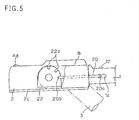
- a lock mechanism for locking the handle 1 has, for example, a structure as shown in Fig. 5.
- a lever 20 is coupled to the inner barrel 18 (see Fig. 2) in such a way that a pin 20a provided integrally with the lever 20 is movably placed in a slot 1d provided in the handle 1.
- a locking plate 22 having a plurality of grooves 22a is provided on an outer wall of the coupling member 2.
- a tip portion 20b of the lever 20 engages with one of the grooves 22a formed in the locking plate 22, and thereby the handle 1 is locked.
- an unlocking button 12 is moved rightward as seen in Fig. 5, the pin 20a moves along the slot 1d together with the inner barrel 18, and thus the tip portion 20b is unlocked from the groove 22a, allowing rotation of the handle 1.
- Fig. 7A is a side view of the handle of the electric vacuum cleaner of a second embodiment of the invention.
- a brush 13 is provided in the handle 1 shown in Fig. 2.
- the handle 1 has a hole 1c formed in its mount 1b, and, into this hole 1c, a supporting shaft 21 is fitted so that the handle 1 is rotatable about the supporting shaft 21.
- a brush 13 is formed at the free end of the handle 1.
- a covering member 14 is provided so as to be slidable relative to the handle 1.
- the covering member 14 has a lever 15 provided integrally therewith.
- the lever 15 has a flange portion 15a, which is loaded, by a compression spring 17, with a force that tends to move it toward the supporting shaft 21 relative to a fixed plate 16 provided on the mount 1b.
- An end portion 15b of the lever 15 makes contact with a cam 22 that is provided on the supporting shaft 21 so as to protrude axially.
- Figs. 8A and 8C are sectional views, as seen from the side, of the principal portion of the handle of the electric vacuum cleaner of a third embodiment of the invention, and Fig. 8B is an enlarged view of the portion indicated by D in Fig. 8A.
- a brush 13 is provided integrally with the inner barrel 18 of the handle 1 shown in Fig. 2. More specifically, the inner barrel 18 has a nozzle 24 formed integrally therewith, and, at the tip end of this nozzle 24, a brush 13 is provided.
- a covering member 23 is provided slidably between the nozzle 24 and the outer barrel 1f of the handle 1.
- the covering member 23 has a stopper 23a.
- the stopper 23a slides along a slot 1g formed in the outer barrel 1f, and thereby restricts the movement stroke of the covering member 23.
- the covering member 23 is loaded with a force that tends to move it so as to cover the brush 13 by a compression spring 7.
- the inner barrel 18 has an air inlet port 18a that permits the space between the nozzle 24 and the outer barrel 1f to communicate with the inside of the inner barrel 18.
- the extension pipe 6 (see Fig. 48) is removed from the coupling member 2, and instead the handle 1 is rotated to that position.
- the suction force acts on the covering member 23 through the air inlet port 18a.
- the covering member 23 moves in the direction indicated by the arrow E1 so as to uncover the brush 13.
- the compression spring 7 causes the covering member 23 to move in the direction indicated by the arrow E2.
- the resulting state, in which the brush 13 is covered by the covering member 23, is shown in Fig. 8C.
- This structure serves the same purpose as that of the second embodiment.
- FIGs. 9A and 9B are sectional views, as seen from the side, of the principal portion of the handle of the electric vacuum cleaner of a fourth embodiment of the invention.
- a coupling member 2 is composed of a fixed portion 30 and a rotatable portion 31.
- the fixed portion 30 has an extension pipe connection portion 30a in which an extension pipe connection aperture 2a is formed.
- the extension pipe connection portion 30a has a lock mechanism 4, similar to the one shown in Fig. 2, for locking an extension pipe 6 (see Fig. 48).
- the rotatable portion 31 rotates about a supporting shaft 21 while sliding along a cylindrical surface 30c of the fixed portion 30.
- the rotatable portion 31 and the extension pipe connection portion 30a are coupled together by a hose 25.
- the rotatable portion 31 has a hose connection aperture 31a to which the hose 3 is connected.
- a handle 1 is formed integrally with the rotatable portion 31. The hose 3 and the handle 1 rotate together, and can be locked in a desired position by a lock mechanism (not shown).
- connecting together the rotatable portion 31 and the extension pipe connection portion 30a with a flexible hose 25 makes it possible to change easily the angle of the handle 1, which is integral with the hose 3.
- the handle 1 by rotating the handle 1 to keep it in an upright position relative to the fixed portion 30 when, for example, cleaning is suspended for a while, it is possible to increase the height from the floor surface to the free-end surface (not shown) of the handle 1. This reduces the stoop that the user needs to make to hold the handle 1 when restarting cleaning, and thereby reduces the burden on the user.
- Fig. 10 is a side view of the principal portion of the handle of the electric vacuum cleaner of a fifth embodiment of the invention.
- a handle 1 is formed integrally with a coupling member 2, and the handle 1 is divided axially into a front portion 1h and a rear portion 1k.
- the rear portion 1k is supported by a supporting member 27 so as to be rotatable relative to the front portion 1h, and the rear portion 1k is lockable at a desired angle. This makes it possible to change easily the angle of the handle 1 and thereby achieve the same purpose as achieved in the fourth embodiment.
- FIGs. 11A and 11B are side views of the principal portion of the handle of the electric vacuum cleaner of a sixth embodiment of the invention.
- a handle 1 is formed integrally with a coupling member 2, and the handle 1 is divided axially into a front portion 1h and a rear portion 1k, with an inclined interface 1m between them.
- the rear portion 1k is supported by a supporting member 28 so as to be rotatable about an axis In perpendicular to the inclined interface 1m.
- the rear portion 1k can be rotated and locked, for example, with the handle 1 in a bent state, as shown in Fig. 11B. This makes it possible to change easily the angle of the handle 1 and thereby achieve the same purpose as achieved in the fourth embodiment.
- Fig. 12 is a sectional view, as seen from the side, of the handle of the electric vacuum cleaner of a seventh embodiment of the invention.
- a nozzle 24 slidable in the direction indicated by the arrow E is provided inside the handle 1 of the electric vacuum cleaner of the fourth embodiment shown in Fig. 9.
- a brush 13 is formed at the tip end of the nozzle 24, a brush 13 is formed.
- the nozzle 24 has an opening 1p formed so as to open to a hose connection portion 31a. Accordingly, the air sucked in through an extension pipe connection aperture 2a flows through this opening 1p to the hose 3.
- This structure makes it possible to use the handle 1 as a dusting brush as in the second embodiment, and thereby eliminates the need to take a dusting brush out of the body 9 of the electric vacuum cleaner (see Fig. 48) and fit it into the extension pipe connection aperture 2a. This enhances user-friendliness, and also helps prevent loss of a dusting brush. Moreover, since the brush 13, with dust and the like clung thereto, is kept covered when not in use, it does not spoil the appearance.
- Fig. 13 is an external view of the electric vacuum cleaner of an eighth embodiment of the invention.
- a nozzle unit 8 having a nozzle (not shown)
- a first pipe 35 is supported so as to be rotatable in the direction indicated by the arrow J1.
- a second pipe 36 is supported so as to be rotatable in the direction indicated by the arrow J2.
- an extension pipe 6 is connected to the second pipe 36.
- the extension pipe 6 is divided into a front portion 6a and a rear portion 6b.
- a hose 3 is connected to a body 9 of the electric vacuum cleaner.
- a coupling member 2 is coupled that has a handle 1 to be held by the user and an operation switch 10 to be operated to control the operation of the electric vacuum cleaner.
- the coupling member 2 is coupled to the extension pipe 6, and thus dust suction from the nozzle is achieved.
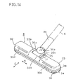
- Figs. 14 and 15 are a perspective view and a bottom view showing the detail of the nozzle unit 8.
- the nozzle unit 8 has a body case 32, which is composed of a lower case 34 having a nozzle 34a formed in its bottom surface, an upper case 33 to which the first pipe 35 is coupled, and a bumper 38 fitted between the upper and lower cases 33 and 34.
- the bumper 38 protects the nozzle unit 8 from scratches and cracks that may result from its collision with a wall or a piece of furniture.
- a rotary brush 40 is provided on the bottom surface of the lower case 34.
- an air inlet 33d (see Fig. 14) is provided to allow air to be sucked in to make the rotary brush 40 rotate.
- the first pipe 35 has a sliding portion 35a having an arc-shaped cross section that slides along the inner surface of a guide portion 33a having an arc-shaped cross section provided in the upper case 33. As a result, the first pipe 35 is so supported as to be rotatable in the direction indicated by the arrow J1 within an opening 33b.
- the second pipe 36 has a sliding portion 36a that slides along the inner surface of a supporting portion 35b provided in the first pipe 35. As a result, the second pipe 36 is so supported as to be rotatable in the direction indicated by the arrow J2.
- the air sucked in through the nozzle 34a and flowing in the direction indicated by the arrow K1 then flows in the direction indicated by the arrow K2 toward the first pipe 35.
- the air then flows through the first and second pipes 35 and 36 as indicated by the arrows K3 and K4, then flows through the extension pipe 6, and then reaches the body 9 of the electric vacuum cleaner.
- the first and second pipes 35 and 36 are coupled together in such a way that the air flow passages (K3 and K4) through the first and second pipes 35 and 36 are arranged in a straight line when the nozzle unit 8 is used in the lateral position.
- the rotation axis 36c of the second pipe 36 is kept perpendicular to the air flow passage (K3) through the first pipe 35.
- Fig. 19 is a top view of the nozzle unit 8 with the upper cover 33 removed.
- the sliding portion 35a of the first pipe 35 is arranged inside the body case 32, which is substantially rectangular, as seen from above.
- the first pipe 35 has a rotation axis 35c substantially at the center of the depth W3 (i.e. the shorter sides) of the body case 32. Accordingly, there is no need to provide a protruding coupling portion 32a (see Fig. 49) as is provided in the conventional example, and thus it is possible to reduce the depth W3 of the nozzle unit 8 and thereby make the nozzle unit 8 compact and light-weight.
- the nozzle unit 8 is used in the longitudinal position, there exists no obstacle like the coupling portion 32a, and thus it is possible to achieve enhanced user-friendliness.
- the rotation axis 36c (see Fig. 17) of the second pipe 36 lies substantially at the center of the nozzle unit 8 in the direction of the longer sides thereof. This ensures that, when the nozzle unit 8 is used in the longitudinal position, the applied force is borne substantially at the center of the body case 32. As a result, a proper balance is obtained when the nozzle unit 8 is moved back and force in the direction H (see Fig. 17). This helps reduce staggering motion of the nozzle unit 8 and thereby enhance user-friendliness.
- the first and second pipes 35' and 36' are arranged within the body case 32 in the direction of its depth. This makes it possible to perform cleaning of an area as narrow as the width W3 of the body case 32.
- the first pipe 35 is substantially parallel to the floor surface. This makes it possible to insert the nozzle unit 8 with ease deep into a narrow area such as a gap below a bed, and thus leads to enhanced user-friendliness.
- the first pipe 35 is rotatable from a position substantially parallel to the floor surface to a position substantially perpendicular thereto. This is achieved by a rotation mechanism having a structure as shown in Fig. 20, which is a sectional view thereof as seen from the side.
- the sliding portion 35a of the first pipe 35 slides along the inner surface of the guide portion 33a of the upper case 33.
- the opening 33b of the upper case 33 needs to be considerably large.
- the lengths L1 and L2 of the front and rear portions of the sliding portion 35a have limits because of the first pipe 35 colliding with the upper and lower cases 33 and 34. Accordingly, between the opening 33b and the sliding portion 35a, an opening, for example as indicated by M, is formed in an upper portion of the body case 32.
- an opening for example as indicated by M, is formed in an upper portion of the body case 32.
- a similar opening is formed in a rear portion (i.e. on the right in Fig. 20) of the body case 32.
- the fixed member 42 has an arc-shaped cross section. A fitting portion 42a' formed at one end of the fixed member 42 engages with an engagement portion 34d (see Fig. 20) of the lower case 34, and a fitting portion 42a formed at the other end thereof is fitted into projections 34c provided on the lower case 34 in such a way as to pull the fixed member 42, which has resilience like a plate spring. In this way, the fixed member 42 is fixed securely.
- the engagement member 41 has an arc-shaped cross section, and is so arranged as to slide along the inner surface of the sliding portion 35a of the first pipe 35 and along the outer surface of the fixed member 42.
- the engagement member 41 and the fixed member 42 have cylindrical surfaces 41e and 42e and openings 41c and 42c. Through these openings 41c and 42c, the flow of the sucked air flows to the inside of the first pipe 35.
- the fixed member 42 has flanges 42f formed at both sides thereof. These flanges 42f make contact with the inner surface of the guide portion 33a. This helps shut off the flow of air that flows from the sides of the engagement member 41 along the outer surface of the engagement member 41 to the opening 33b as indicated by the arrows P1 and P2, and thereby prevent leakage of the sucked air.
- engagement claws 41b and 41d (see Fig. 20) provided on the engagement member 41 engage with engagement claws 35f and 35g provided on the sliding portion 35a. This allows rotation of the engagement member 41.
- engagement claws 41f and 41g provided on the inner surface of the engagement member 41 engage with engagement claws 42b and 42d (see Fig. 20) provided on the fixed member 42. This restricts rotation of the engagement member 41.
- the air flow passage in the air inflow portion 35h gradually widens.
- the inclination of the first pipe 35 becomes equal to about 45 °
- the engagement claw 35g provided on the sliding portion 35a engages with the engagement claw 41d provided on the engagement member 41.
- the air flow passage in the air inflow portion 35h has the maximum cross-sectional area.
- the air flow passage in the air inflow portion 35h is kept having the maximum cross-sectional area.
- the first pipe 35 strikes an end surface 33c of the opening 33b of the upper case 33, rotation of the first pipe 35 is restricted.
- the engagement claw 42d provided on the fixed member 42 engages with the engagement claw 41g provided on the engagement member 41, and thereby rotation of the engagement member 41 is restricted.
- the structure as described above makes it possible to rotate the first pipe 35 from a position substantially parallel to the floor surface to a position substantially perpendicular thereto.
- the nozzle unit 8 is used in the lateral position, which is more frequently the case than otherwise, and in addition when the inclination of the first pipe 35 is in the range from about 45 ° to 60 °, which is more frequently the case than otherwise, by rotating the first pipe 35 once to the position substantially parallel to the floor surface and then backward, it is possible to maximize the cross-sectional area of the air flow passage in the air inflow portion 35h.
- the air flow passage in the air inflow portion 35h has the maximum cross-sectional area, and thus it is possible to achieve high suction efficiency.
- the air flow passage in the air inflow portion 35h it is also possible to provide another engagement member between the engagement member 41 and the fixed member 42.
- a shield portion 41a is provided that makes contact with the inner surface of the upper case 33. If dust or the like, entering through the opening 33b of the upper case 33, collects in the lower front portion (indicated by N) of the fixed member 42, it is difficult to remove it.
- the shield portion 41a serves to shield this gap between the fixed member 42 and the upper case 33. As a result, even if dust or the like enters through the opening 33b, it collects on the shield portion 41a, which is closer to the opening 33b, and thus it is easy to remove it.
- Fig. 24 is an exploded perspective view of another example of the structure of the engagement member 41.
- the engagement member 41 is extended in the direction of its longer sides, and has slots 41f provided in the cylindrical surfaces 41e' constituting the extended portion thereof.
- the flow of air sucked through the air inlet 33d (see Fig. 14) of the upper case 33 into the nozzle unit 8 flows through the slots 41f and blows on the blades 50 (see Fig. 20) of the rotary brush 40, thereby rotating the rotary brush 40.
- This causes rotating brushes 47 to rotate and thereby rake up dust from the floor surface.
- the dust together with the flow of the sucked air, flows toward the first pipe 35 as indicated by the arrow K2 in Fig. 16.
- the air sucked in through the upper case 33 immediately flows toward the first pipe 35.
- the air sucked in first flows through the slots 41f to a portion closer to the blades 50 and then flows toward the first pipe 35. This makes it possible to rotate the rotary brush 40 efficiently and thereby increase suction efficiency.
- the positions of the slots 41f vary according to the rotation direction of the first pipe 35 as the first pipe 35 rotates, but the slots 41f remain substantially in the same positions relative to the first pipe 35. Thus, it is possible to keep at all times the slots 41f in such positions relative to the first pipe 35 that the sucked air efficiently blows on the blades 50.
- Fig. 25 is an exploded perspective view of the portion around a caster 39 of the nozzle unit 8 of the embodiment under discussion.
- a caster 39 is supported by a caster mount 46, which has a pair of supporting ribs 46c each having a horizontally long slot 46e. Into these slots 46e, a caster shaft 39a fixed to the caster 39 is loosely fitted. The caster shaft 39a may be formed integrally with the caster 39 to reduce the number of components.
- the caster mount 46 has a pivot 46a having resilience radially.
- a recessed portion 34e is provided that has a pivot socket 45 formed integrally.
- the pivot 46a is fitted into the pivot socket 45.
- the pivot 46a of the caster mount 46 has a stopper 46b formed at the end. This stopper 46b engages with an end surface 45a of the pivot socket 45 so as to prevent the caster 39 from dropping out.
- the recessed portion 34e is so formed as to have an opening in the circumferential surface 34f of the lower case 34. This helps prevent dust or the like from collecting in the recessed portion 34e.
- the caster 39 and the caster mount 46 are so formed as not to protrude from the circumferential surface 34f. This helps prevent damage to the caster 39 or scratches on a wall or a piece of furniture resulting from collision between them during cleaning.
- reinforcing ribs 46d are provided so as to bridge between the pair of supporting ribs 46c in order to reinforce the supporting ribs 46c and thereby obtain higher reliability in the function of the caster.
- the caster 39 is fitted so as to be freely rotatable about the pivot 46a. This ensures smooth change of the movement direction of the nozzle unit 8 between directions G and H (see Fig. 14). Moreover, the caster 39 does not slide but rolls, and thereby prevents scratches on the flooring or the like. Moreover, since the caster shaft 39a is supported by the slots 46e, the caster 39 can move translationally. This makes the caster 39 more susceptible to the moment that tends to change the movement direction and thereby ensures smoother change of the movement direction.
- the caster 39 it is preferable to form the caster 39 so as to have a smaller diameter in the edge portions 39b" of its circumferential surface than in the central portion 39b' thereof, because this makes it possible to keep the caster 39 substantially in point contact with the floor surface and thereby make it even more susceptible to the moment that tends to change the movement direction.
- Fig. 26 is an exploded perspective view showing another example of the structure of the portion around a caster 39.
- a bearing surface 46f of a caster mount 46 On a bearing surface 46f of a caster mount 46, a plurality of balls 49 are arranged by being positioned by a ring 48. The balls 49 are held between the bearing surface 46f and a bearing surface (not shown) provided on the bottom surface of a fixed base 50.
- the caster mount 46 is fixed to a recessed portion 34e (see Fig. 25) by a pin 47.
- This structure serves the same purpose as the previously described structure does.
- the first and second pipes 35 and 36 are rotated, from the state shown in Fig. 13 described earlier, in the directions indicated by arrows J1 and J2, respectively.
- the extension pipe 6, the coupling member 2, and the hose 3 move together, bringing the handle into a state pointing to the side as shown in Fig. 27.
- a button 53 by operating a button 53, it is possible to rotate the coupling member 2 in the direction indicated by the arrow Q relative to the extension pipe 6 as shown in Fig. 28, so that the handle 1 and the operation switch 10 point upward.
- the handle 1 and the operation switch 10 can be used in the same way as when the nozzle unit 8 is used in the lateral position, and thus enhanced user-friendliness is achieved in cleaning.
- a coupling groove (a first groove) 55 is provided circumferentially.
- a plurality of locking grooves (second grooves) 56 are provided around the same circumference.
- a lock mechanism 60 for coupling the extension pipe 6 is provided on the coupling member 2.
- the lock mechanism 60 is supported so as to be rota table about a rotation axis 60a.
- the lock mechanism 60 has, at one end thereof, a button 53 (a disengaging member) that protrudes through a hole 2c provided in the coupling member 2.
- the lock mechanism 60 has, at the other end thereof, a first and a second projection (a first and a second engagement member) 57 and 58 that can engage with the first and second grooves 55 and 56, respectively.
- the button 53 is loaded with a force that tends to move it upward as seen in the figures by a compression spring 54. Accordingly, the first and second projections 57 and 58 are pressed against the extension pipe 6. With the button 53 pressed with a finger, the extension pipe 6 is inserted into the coupling member 2. By releasing the finger from the button 53, since the first projection 57 has a smaller rotation radius than the second projection 58 with respect to the rotation axis 60a as shown in Fig. 31, it is possible to engage the first projection 57 with the coupling groove 55 without engaging the second projection 58 with the locking grooves 56. In this way, the coupling member 2 and the extension pipe 6 are rotatably coupled together.
- the second projection 58 slides along the outer surface of the extension pipe 6, and then the second projection 58 engages with one of the locking grooves 56 as shown in Figs. 29 and 30 described previously, locking the coupling member 2 in a predetermined position relative to the extension pipe 6.
- Removal of the extension pipe 6 from the coupling member 2 is achieved in the following manner.
- the button 53 a disengaging member
- the second projection 58 is disengaged from the locking groove 56.
- the button 53 further with a finger as shown in Fig. 32, the first projection 57 is disengaged from the coupling groove 55. In this state, by pulling out the extension pipe 6, it is removed from the coupling member 2.
- the locking grooves 56 are arranged at three locations, i.e. at the location indicated by solid lines where the button 53 of the lock mechanism 60 points upward (hereafter referred to as the "normal position") and at the locations indicated by dash-and-dot lines 90 ° apart rightward and leftward from the normal position (hereafter referred to as the "90 ° positions").
- the coupling member 2 When the nozzle unit 8 is used in the lateral position (see Fig. 13), the coupling member 2 is in the normal position. When the nozzle unit 8 is used in the longitudinal position (see Fig. 28), the coupling member 2 is in one of the 90 ° positions. Thus, in either case, the handle 1, the operation switch 10, and the button 53 can be made to point upward.
- the locking grooves 56 may be arranged at other locations than described above.
- the locking grooves 56 have, as their circumferential wall surfaces, inclined surfaces 56a.
- the second projection 58 runs on to the inclined surface 56a against the load with which it is loaded by the compression spring 54, allowing switching between the normal and 90 ° positions. This makes switching of the rotation position easy.
- the locking grooves 56 at the 90 ° positions have, as their wall surface 56b farther from the normal position, non-inclined surfaces, so that these surfaces serve as stoppers that restrict the rotation range by being struck by the second projection 58 and thereby prevent the coupling member 2 from being rotated out of the rotation range. This makes switching to the 90 ° positions easier and thereby enhances user-friendliness.
- Fig. 35 is a sectional view of the portion of the extension pipe 6 at which the coupling groove 55 is formed.
- grooves 55c deeper than the coupling groove 55 are provided.
- inclined surfaces 55a and stopper surfaces 55b are provided to allow easy switching of the rotation position.
- Figs. 36 and 37 are a sectional view and a partial sectional view, respectively, of another example of the structure of the lock mechanism 60 for locking together the coupling member 2 and the extension pipe 6.
- This lock mechanism 60 is different from the lock mechanism 60 shown in Fig. 29 in that the second projection 58 is composed of a ball 58' loaded with a force by a compression spring 52 and is provided separately from the first projection 57.
- the locking groove 56 has an inclined surface 56c as its wall surface closer to the coupling member 2, i.e. the wall surface that lies in the direction in which the extension pipe 6 is pulled out (along the rotation axis).
- An inclined surface is preferable here because it ensures smooth movement of the ball 58' and thus easy removal of the extension pipe 6.
- Coupling between the coupling member 2 and the extension pipe 6 does not necessarily have to be achieved by engaging a groove (the coupling groove 55 and the locking grooves 56) provided in the outer surface of the extension pipe 6 with an engagement member (the first and second projections 57 and 58 and the ball 58') provided on the coupling member 2, but may be achieved in any other manner.
- a groove in the coupling member 2 and provide an engagement member on the extension pipe 6 or it is possible to provide a groove in the inner surface of the extension pipe 6.
- Fig. 39 is a sectional view, as seen from the side, of the nozzle unit 8 of the electric vacuum cleaner of a ninth embodiment of the invention.
- the nozzle unit 8 of this embodiment is intended to replace that of the eighth embodiment shown in Fig. 14, and therefore such components as are found also in the eighth embodiment are identified with the same reference numeral.
- the electric vacuum cleaner as a whole has the same structure as shown in Fig. 13.
- the nozzle unit 8 has a body case 32, which is composed of a lower case 34 having a nozzle (not shown) formed in its bottom surface, an upper case 33 to which a first pipe 35 is coupled, and a bumper 38 fitted between the upper and lower cases 33 and 34.
- a second pipe 36 is coupled to the first pipe 35.
- an extension pipe 6 (see Fig. 13) is coupled, which is comparatively long.
- the first pipe 35 has a sliding portion 35a having an arc-shaped cross section that slides along the inner surface of a guide portion 33a having an arc-shaped cross section of the upper case 33.
- the first pipe 35 is so supported as to be rotatable in the direction indicated by the arrow J1 within an opening 33b.
- a bottom surface of the first pipe 35 is fitted to the second pipe 36 with a screw 63 so as to be rotatable about a rotation axis 36c, and is covered by a cover 64.
- a top surface of the first pipe 35 is fitted to a pipe cover 62 with a screw 65 so as to be rotatable about the rotation axis 36c.
- the pipe cover 62 is fixed to the second pipe 36 with screws 66.
- the elevation (depression) angle of the extension pipe 6 can be changed by means of the first pipe 35.
- the elevation (depression) angle of the extension pipe 6 can be changed by means of the second pipe 36.
- Fig. 40 shows how the first and second pipes 35 and 36 are coupled together.
- the first pipe 35 has an opening 35d formed so as to extend through a range of angles ⁇ 3.
- the flow of the sucked air flows through this opening 35d to the second pipe 36.
- An end surface 35e of the opening 35d is hit by a stopper portion 36b of the second pipe 36, and thereby the rotation range ⁇ 2 of the second pipe 36 in the direction J2 is restricted.
- shutters 67a and 67b are provided on the inner surface of the first pipe 35.
- the shutters 67a and 67b are loaded with forces that tend to move them clockwise and counter-clockwise, respectively, by a force-loading spring 69, and are so arranged as to be slidable along the inner surface of the first pipe 35.
- the click mechanism has a steel ball 68 and a locking plate 61 provided between the pipe cover 62 and the first pipe 35.
- Fig. 42 shows the detail of the click mechanism.
- the first pipe 35 has a boss 35f, into which a compression spring 70 is fitted.
- a locking plate 61 having a hole 61a is fixed.
- a steel ball 68 is arranged between the locking plate 61 and the compression spring 70. Engaging the steel ball 68 with the hole 61a produces a click.
- a predetermined rotation force is required to rotate the second pipe 36, which is integral with the pipe cover 62. This prevents free rotation of the second pipe 36 and thereby prevents degradation of cleaning efficiency due to staggering motion of the body case 32.
- a felt ring 71 is fitted to the boss 35f to prevent entry of dust and thereby prevent variation over time of the clicking force produced by the steel ball 68.
- the steel ball 68 retracts against the force with which it is loaded by the compression spring 70. Then, the steel ball 68 rolls along the inner surface of the locking plate 61. Therefore, when the nozzle unit 8 is used in the longitudinal position, the second pipe 36 can rotate freely.
- a rotary brush 40 has, on its shaft portion 49, blades 50 made of a flexible material such as rubber and brushes 47.
- the blades 50 each have a plurality of through holes 50a formed so as to extend in the direction of a radius of the rotary brush 40 and arranged in a line extending in the direction of the length of the rotary brush 40.
- the air sucked through the air inlet 33d provided in the upper case 33 into the body case 32 flows into the shaft portion 49 from the side of the rotary brush 40. The air then flows through the shaft portion 49 and then blows out through the through holes 50a.
- the rotary brush 40 is fixed inside the body case 32 in such a way as to be loaded, at one end, with a force by a compression spring 78 through an attachment/detachment button 75.
- the attachment/detachment button 75 is, at its shaft portion 75b, pivoted on the body case 32 so as to be rotatable in the direction indicated by the arrow V1, with a certain amount of play 77 secured so as to permit the shaft portion 75b to move upward as seen in the figure within the body case 32.
- the lower case 34 has a projecting rib 34e.
- the projecting rib 34e restricts rotation of the attachment/detachment button 75 and thereby prevents the rotary brush 40 from dropping out.
- a button portion 75a of the attachment/detachment button 75 is pulled up in the direction indicated by the arrow V2, the shaft portion 75b moves as much as the play 77 permits.
- the attachment/detachment button 75 can be rotated without interference with the projecting rib 34e. This allows attachment and detachment of the rotary brush 40.
- Figs. 44 and 45 are a sectional view, as seen from the side, and a bottom view, respectively, of the nozzle unit of the electric vacuum cleaner of a tenth embodiment of the invention.
- the electric vacuum cleaner as a whole has the same structure as the conventional example.
- the nozzle unit 8 has an outer casing composed of an upper case 33 and a lower case 34.
- an extension pipe 6 (see Fig. 48) is connected to a body 9 of the electric vacuum cleaner.
- a second pipe 36 is connected to the extension pipe 6, a second pipe 36 is connected.
- a first pipe 35 is coupled.
- the first pipe 35 is held between the upper and lower cases 33 and 34.
- the elevation (depression) angle of the extension pipe 6 can be adjusted by means of the first pipe 35.
- a nozzle 34a is formed so as to open toward the floor surface.
- the dust sucked in through the nozzle 34a flows, together with the flow of the sucked air, through the air flow passage 89 in the direction indicated by the arrow K3 to the body 9 of the electric vacuum cleaner, and thereby dust collection is achieved.
- casters 37 and 39 In front of and behind the nozzle 34a are provided casters 37 and 39 that rotate while keeping the distance between the nozzle 34a and the floor surface constant, allowing movement of the nozzle unit 8.
- a bumper 38 which serves as a shock absorber when the nozzle unit 8 collides with a wall or the like.
- a brush member 51 for raking up dust clung to a carpet or the like.
- a flexible member 52 In front of the nozzle 34a is provided a flexible member 52. At both ends of the flexible member 52, aid pieces 81 are fitted so as to make contact with the floor surface. Thus, as the nozzle unit 8 moves back and forth, the flexible member 52 is made to rotate by the friction force between the aid pieces 81 and the floor surface.
- Fig. 46 is an exploded perspective view showing the detail of the flexible member 52.
- a sealing piece 52b is provided so as to project therefrom.
- insertion shafts 52e are formed, which are fitted into insertion holes 81a of the aid pieces 81.
- On the sealing piece 52b are provided a plurality of conical projections 52g.
- the projections 52g are arranged in two rows X1 and X2 along the length of the sealing piece 52b.
- engagement pieces 52f are provided on the insertion shafts 52e, and engagement grooves 81b into which the engagement pieces 52f are fitted are provided in the insertion holes 81a of the aid pieces 81.
- the aid pieces 81 each have three fin-like portions 81c, 81d, and 81e formed so as to extend radially around the insertion holes 81a.
- the fin-like portions 81c, 81d, and 81e are made so long as to make contact with the floor surface.
- the supporting shaft 52a, the sealing piece 52b, and the projections 52g are formed integrally by molding out of a hard resin material such as ABS resin, polypropylene, or polyethylene.
- the aid pieces 81 are formed out of a soft material such as hard rubber.
- Fig. 47 is a detail sectional view showing the principal portion of the front portion of the nozzle unit 8, with the above-described flexible member 52 attached.
- the supporting shaft 52a is held by a groove 84 formed by a curved-surface plate 82 having a substantially J-like shape provided on the lower case 34 and a curved-surface portion 83b of a detachable engagement claw 83.
- the supporting shaft 52a of the flexible member 52 is fitted into this groove 84 and is held by the engagement claw 83 so as not to drop off.
- the sealing piece 52b strikes a front stopper portion 83a provided in the engagement claw 83 and a rear stopper portion 82a provided in the curved-surface plate 82, and thereby the rotation range ⁇ of the flexible member 52 is restricted.
- the sealing piece 52b When the nozzle unit 8 is moved forward, by the friction force between the fin-like portions 81c and 81d of the aid pieces 81, which are in contact with the floor surface, and the floor surface, the sealing piece 52b is rotated backward so as to strike the rear stopper portion 82a. At this time, the fin-like portion 81e makes contact with the floor surface, and thus an opening is formed in front of the nozzle 34a to allow easy suction of large-particle dust and dust by a wall.
- the sealing piece 52b When the nozzle unit 8 is moved backward, by the friction force between the fin-like portions 81e and 81d, which are in contact with the floor surface, and the floor surface, the sealing piece 52b is rotated forward so as to strike the front stopper portion 83a. At this time, the fin-like portion 81c makes contact with the floor surface. Thus, the sealing piece 52b ensures that no opening is left in front of the nozzle 34a, and thereby increases the degree of vacuum at the nozzle 34a and thus the suction power.
- the casters 37 and 39 sink into the carpet or the like.
- the projections 52g of the sealing piece 52b rake up fluffy dust, hair, and the like clung to the carpet or the like so as to allow such dust to be sucked through the nozzle 34a.
- the projections 52g are conical, the fluffy dust, hair, and the like raked up can be removed therefrom with ease by the suction force. This helps prevent clinging of raked-up dust.
- arranging the projections in a plurality of rows X1 and X2 makes it possible to efficiently rake up fluffy dust, hair, and the like at different depths in a carpet or the like.
- the projections may be arranged in more than two rows.
- by arranging the projections 52g near the lower edge 52h (see Fig. 46) of the sealing piece 52b it is possible to rake deep into the surface to be cleaned and thereby further increase dust collection efficiency.
Landscapes
- Engineering & Computer Science (AREA)
- Mechanical Engineering (AREA)
- Electric Vacuum Cleaner (AREA)
- Nozzles For Electric Vacuum Cleaners (AREA)
Description
- The present invention relates to a nozzle unit for an electric vacuum cleaner.
- A conventional electric vacuum cleaner has a structure as shown in Fig. 48. A
nozzle unit 8 having a nozzle (not shown) formed in its bottom surface is coupled to anextension pipe 6. Theextension pipe 6 is coupled through acoupling member 2 to aflexible hose 3. The hose is coupled to thebody 9 of the electric vacuum cleaner. The flow of air sucked in through the nozzle flows through theextension pipe 6, thecoupling member 2, and thehose 3, and then reaches thebody 9 of the electric vacuum cleaner, thereby achieving suction of dust. - The
coupling member 2 has ahandle 1 formed integrally therewith, which is held by the user during cleaning. Thecoupling member 2 also has anoperation switch 10, which is used during cleaning to control a rotary brush (not shown) provided in thenozzle unit 8 and to control thebody 9 of the electric vacuum cleaner. - The
nozzle unit 8 is shown in more detail in Fig. 49. Thenozzle unit 8 has abody case 32, of which acoupling portion 32a supports afirst pipe 35 in such a way that thefirst pipe 35 is rotatable in the direction indicated by the arrow J1. Thefirst pipe 35 supports asecond pipe 36 in such a way that thesecond pipe 36 is rotatable in the direction indicated by the arrow J2. The above-mentionedextension pipe 6 is coupled to thissecond pipe 36. - Thus, the
first pipe 35 allows the elevation (depression) angle of theextension pipe 6 to vary when thenozzle unit 8 is moved in the direction indicated by the arrow G. For example, thefirst pipe 35 is rotated in the direction J1 so that theextension pipe 6 becomes substantially upright, and then thesecond pipe 36 is rotated in the direction J2. Thus, thesecond pipe 36 allows the elevation (depression) angle of theextension pipe 6 to vary when thenozzle unit 8 is moved in the direction indicated by the arrow H. - On the two side surfaces of the
coupling portion 32a of thebody case 32,casters 39 are provided that roll on the floor so as to allow thenozzle unit 8 to move. The air sucked in in the direction indicated by the arrow F1 through the nozzle (not shown) formed in the bottom surface of thebody case 32 flows in the direction indicated by the arrow F2 toward thecoupling portion 32a. The air then flows through the first andsecond pipes extension pipe 6, and then reaches the electricvacuum cleaner body 9. - In ordinary cleaning, as shown in Fig. 50, the first and
second pipes nozzle unit 8 is moved in the direction indicated by the arrow G. In cleaning of a narrow area such as a gap between pieces of furniture, as shown in Fig. 51, thesecond pipe 36 is rotated, and dust suction is performed as thenozzle unit 8 is moved in the direction indicated by the arrow H. - In an electric vacuum cleaner of this type, the
handle 1 is fixed to thecoupling member 2 so as to be integral therewith. Therefore, in cleaning of an area such as a gap below a bed, the user needs to take a low position to hold thehandle 1 while moving thenozzle unit 8. This imposes an undue burden on the user, and is thus undesirable in terms of user-friendliness. - In some cases, to perform dust suction in a narrow area, an auxiliary nozzle is used, such as a crevice nozzle having a flat tip or a dusting brush having a brush at its tip. In such cases, first, the
extension pipe 6 needs to be removed from thecoupling member 2. Then, an auxiliary nozzle (not shown) stored inside the electricvacuum cleaner body 9 needs to be taken out and coupled to thecoupling member 2 so as to be ready for use. This requires complicated handling, and is thus undesirable in terms of user-friendliness. There is also a possibility of loss of an auxiliary nozzle. - Handling of an auxiliary nozzle can be simplified if the auxiliary nozzle is removably held on the
extension pipe 6. However, this requires the auxiliary nozzle to be kept visible with dust and the like clung to the tip thereof, and thus spoils the appearance. There is also a possibility of loss of an auxiliary nozzle as in the cases described previously. - Moreover, from the
nozzle unit 8, thecoupling portion 32a and the first andsecond pipes nozzle unit 8. (Note here that a depth means the length of the shorter sides of something perpendicular as seen in a plan view.) Thus, thenozzle unit 8 has an unduly large depth W1 relative to the depth W2 of thenozzle 32b (see Fig. 51). This makes cleaning of a gap difficult, and also, by requiring thenozzle unit 8 to be made larger and thus heavier, imposes an undue burden on the user. - Moreover, the air passage is bent in the
first pipe 35 and also in thesecond pipe 36, and thus the suction pressure suffers a great loss. This reduces suction efficiency and increases noise. Furthermore, the range of rotation of thefirst pipe 35 in thedirection J 1 is so narrow that the elevation (depression) angle of theextension pipe 6 can be varied only between approximately 30 ° and 70 °. This makes it difficult to move thenozzle unit 8 so as to reach sufficiently deep into an area such as below a bed where there is only a small gap above the floor, and is thus undesirable in terms of user-friendliness. - The above described problems of narrow elevation angle range of the extension pipe and suction pressure loss are encountered, too, and not solved by a vacuum cleaner nozzle as disclosed in
DE 22 20 815, since first and second air flow passages formed by first and second pipes are bent twice in the course from an entrance of the first pipe to the exit of the second pipe, and since the rotation angle of the second pipe is not substantially perpendicular to the first air flow passage, but is parallel thereto. - An object of the present invention is to provide a nozzle unit for an electric vacuum cleaner that offers improved user-friendliness in cleaning performed with the user taking a low position and in cleaning performed using an auxiliary nozzle. Another object of the present invention is to provide a compact and light-weight nozzle unit for an electric vacuum cleaner that offers improved suction efficiency.
- To achieve the above objects, according to one aspect of the present invention,
a nozzle unit for an electric vacuum cleaner is provided with:
a body case having a nozzle open toward a surface to be cleaned, the body case having a substantially rectangular shape as seen in a plan view;
a first pipe that has a first air flow passage for allowing passage of a flow of air sucked in through the nozzle and that is coupled to the body case so as to be rotatable about a rotation axis parallel to the direction of the longer sides of the nozzle, the first pipe having a sliding portion that slides along the body case as the first pipe rotates, the sliding portion arranged inside the body case as seen in a plan view; and
a second pipe rotatably coupled to the first pipe, the second pipe having a second air flow passage that communicates with the first air passage. - According to the invention, and for achieving an undisturbed air flow and greater freedom for moving of the extension pipe, the first and second air flow passages are arranged substantially along a straight line as seen in a side view throughout from an entrance of the first pipe to an exit of the second pipe, and the second pipe is rotatable about a rotation axis substantially perpendicular to a straight line defined from the entrance of the first pipe to the exit of the first pipe.
- According to this arrangement, the sliding portion of the first pipe is arranged inside the substantially rectangular body case as seen in a plan view so as to be slidable along the body case, and thus the first pipe can be inclined in the direction of the depth (i.e. in the direction of the shorter sides) of the nozzle unit. The air sucked in through the nozzle achieves dust suction by flowing through the first air flow passage inside the first pipe and then through the second air flow passage inside the second pipe, of which the latter can be inclined in the direction of the longer sides of the body case. By rotating the first and second pipes appropriately, it is possible to reduce the depth-direction width of the nozzle unit.
- This and other objects and features of the present invention will become clear from the following description, taken in conjunction with the preferred embodiments with reference to the accompanying drawings in which:
- Fig. 1 is a perspective view of the handle of the electric vacuum cleaner of a first embodiment of the invention;
- Fig. 2 is a sectional view, as seen from the side, of the handle of the electric vacuum cleaner of the first embodiment;
- Fig. 3 is a diagram showing the state of the handle of the electric vacuum cleaner of the first embodiment when it is in the reversed position;
- Fig. 4 is a diagram showing the state of the handle of the electric vacuum cleaner of the first embodiment when it is in the upright position;
- Fig. 5 is a side view of the handle of the electric vacuum cleaner of the first embodiment, illustrating its lock mechanism;
- Fig. 6 is a diagram showing the state of the handle of the electric vacuum cleaner of the first embodiment when the lock mechanism is unlocked;
- Figs. 7A and 7B are side views of the handle of the electric vacuum cleaner of a second embodiment;
- Figs. 8A, 8B, and 8C are sectional views, as seen from the side, of the handle of the electric vacuum cleaner of a third embodiment;
- Figs. 9A and 9B are sectional views, as seen from the side, of the handle of the electric vacuum cleaner of a fourth embodiment;
- Fig. 10 is a side view of the handle of the electric vacuum cleaner of a fifth embodiment;
- Fig. 11A and 11B are side views of a principal portion of the handle of the electric vacuum cleaner of a sixth embodiment;
- Fig. 12 is a sectional view, as seen from the side, of the handle of the electric vacuum cleaner of a seventh embodiment;
- Fig. 13 is a schematic overall view of the electric vacuum cleaner of an eighth embodiment;
- Fig. 14 is a schematic perspective view of the nozzle unit of the electric vacuum cleaner of the eighth embodiment;
- Fig. 15 is a bottom view of the nozzle unit of the electric vacuum cleaner of the eighth embodiment;
- Fig. 16 is a sectional view, as seen from the front, of the nozzle unit of the electric vacuum cleaner of the eighth embodiment;
- Fig. 17 is a schematic perspective view showing the state of the nozzle unit of the electric vacuum cleaner of the eighth embodiment when it is ready for cleaning in another direction;
- Fig. 18 is a side view of the nozzle unit of the electric vacuum cleaner of the eighth embodiment;
- Fig. 19 is a top view of the nozzle unit of the electric vacuum cleaner of the eighth embodiment;
- Fig. 20 is a sectional view, as seen from the side, of the nozzle unit of the electric vacuum cleaner of the eighth embodiment;
- Fig. 21 is an exploded perspective view showing an example of the structure of the rotation mechanism of the nozzle unit of the electric vacuum cleaner of the eighth embodiment;
- Fig. 22 is a sectional view, as seen from the side, of the nozzle unit of the electric vacuum cleaner of the eighth embodiment, showing a state of rotation of the first pipe;
- Fig. 23 is a sectional view, as seen from the side, of the nozzle unit of the electric vacuum cleaner of the eighth embodiment, showing another state of rotation of the first pipe;
- Fig. 24 is an exploded perspective view showing another example of the structure of the rotation mechanism of the nozzle unit of the electric vacuum cleaner of the eighth embodiment;
- Fig. 25 is an exploded perspective view showing an example of the structure of a caster portion of the nozzle unit of the electric vacuum cleaner of the eighth embodiment;
- Fig. 26 is an exploded perspective view showing another example of the structure of a caster portion of the nozzle unit of the electric vacuum cleaner of the eighth embodiment;
- Fig. 27 is a schematic view showing the state of the electric vacuum cleaner of the eighth embodiment when the nozzle unit is in the longitudinal position;
- Fig. 28 is a schematic view showing the state of the electric vacuum cleaner of the eighth embodiment when the nozzle unit is in the longitudinal position and the extension pipe is rotated;
- Fig. 29 is a sectional view of the coupling portion of the electric vacuum cleaner of the eighth embodiment;
- Fig. 30 is a partial sectional view of the coupling portion of the electric vacuum cleaner of the eighth embodiment;
- Fig. 31 is a sectional view showing the state of the coupling portion of the electric vacuum cleaner of the eighth embodiment when the second projection is disengaged;
- Fig. 32 is a sectional view, as seen from the front, of the locking groove of the extension pipe of the electric vacuum cleaner of the eighth embodiment;
- Fig. 33 is an enlarged partial view of Fig. 32;
- Fig. 34 is a sectional view, as seen from the front, of the coupling groove of the extension pipe of the electric vacuum cleaner of the eighth embodiment;
- Fig. 35 is a sectional view showing the state of the coupling portion of the electric vacuum cleaner of the eighth embodiment when the first projection is disengaged;
- Fig. 36 is a sectional view of another example of the structure of the coupling portion of the electric vacuum cleaner of the eighth embodiment;
- Fig. 37 is a partial sectional view of Fig. 36;
- Fig. 38 is a sectional view showing the state when the extension pipe is removed from the state shown in Fig. 36;
- Fig. 39 is a sectional view, as seen from the side, of the nozzle unit of the electric vacuum cleaner of a ninth embodiment;
- Fig. 40 is a front view showing the state of the nozzle unit of the electric vacuum cleaner of the ninth embodiment when the second pipe is in the upright position;
- Fig. 41 is a front view showing the state of the nozzle unit of the electric vacuum cleaner of the ninth embodiment when the second pipe is in the fully inclined position;
- Fig. 42 is a detail view of the principal portion of the click mechanism of the nozzle unit of the electric vacuum cleaner of the ninth embodiment;
- Fig. 43 is a sectional view, as seen from the front, of the nozzle unit of the electric vacuum cleaner of the ninth embodiment;
- Fig. 44 is a sectional view, as seen from the side, of the nozzle unit of the electric vacuum cleaner of a tenth embodiment;
- Fig. 45 is a bottom view of the nozzle unit of the electric vacuum cleaner of the tenth embodiment;
- Fig. 46 is an exploded perspective view of the flexible member of the nozzle unit of the electric vacuum cleaner of the tenth embodiment;
- Fig. 47 is a detail view of the principal portion of the front portion of the nozzle unit of the electric vacuum cleaner of the tenth embodiment;
- Fig. 48 is a perspective view of a conventional electric vacuum cleaner;
- Fig. 49 is a schematic perspective view of the nozzle unit of a conventional electric vacuum cleaner;
- Fig. 50 is a schematic top view showing the state of the nozzle unit of a conventional electric vacuum cleaner when it is in the lateral position; and
- Fig. 51 is a schematic top view showing the state of the nozzle unit of a conventional electric vacuum cleaner when it is in the longitudinal position.
- Hereinafter, embodiments of the present invention will be described with reference to the drawings. Figs. 1 and 2 are a perspective view and a sectional view of the principal portion of the handle of the electric vacuum cleaner of a first embodiment of the invention. The electric vacuum cleaner as a whole has the same structure as the conventional example shown in Fig. 48. In a
coupling member 2, an extension pipe connection aperture 2a is provided into which anextension pipe 6 is inserted. Inside thecoupling member 2, the extension pipe connection aperture 2a communicates with ahose 3 that is inserted through anopening 2d. - To the
coupling member 2, ahandle 1 is fitted through amount 1b (having a U-like shape as seen in a plan view) in such a way that themount 1b sandwiches thecoupling member 2 from the two side surfaces thereof. Themount 1b is rotatably supported on thecoupling member 2 through a supportingshaft 21. Thehandle 1 has the shape of a hollow cylinder and is open at its free-end surface 1a. Moreover, thehandle 1 has aninner barrel 18 slidably provided inside it. - Within a cavity 1r formed in a double-cylinder portion 1e formed inside the
handle 1, theinner barrel 18 is loaded with a force that tends to move it toward thecoupling member 2 by acompression spring 19. Theinner barrel 18 reaches into theopening 2d of thecoupling member 2, and thus astopper portion 2e of thecoupling member 2 restricts rotation of thehandle 1 in the direction indicated by the arrow A. On the other hand, abase plate 2c strikes themount 1b and thereby restricts rotation of thehandle 1 in the direction indicated by the arrow B. In this way, thehandle 1 is locked. - The state shown in Fig. 2 is the standard position of the handle (hereafter the "standard position") that allows a standing user to hold the
handle 1 and move the nozzle unit 8 (see Fig. 48) back and forth with ease. In thehandle 1, an unlockingbutton 12 is provided integrally with theinner barrel 18. The unlockingbutton 12 protrudes through a slot Is so as to be movable along it. When the unlockingbutton 12 is moved rightward as seen in Fig. 2, theinner barrel 18 is unlocked from thecoupling member 2, allowing rotation of thehandle 1 in the direction indicated by the arrow A. -
Reference numeral 4 represents a lock mechanism for theextension pipe 6. A claw portion 4a is loaded with a force by acompression spring 4b, with a supporting portion 4c used as a fulcrum. Thelock mechanism 4 engages with a hole (not shown) provided in theextension pipe 6, and thereby theextension pipe 6 is locked to thecoupling member 2. When abutton portion 4d is pressed, the claw portion 4a retracts from the hole, allowing removal of theextension pipe 6. - In cleaning of a narrow area, the
extension pipe 6 is removed, and then thehandle 1 is rotated, along theimaginary line 100, from the standard position shown in Fig. 2 to the position of the extension pipe connection aperture 2a. The resulting state is shown in Fig. 3. At this time, theinner barrel 18 reaches into the extension pipe connection aperture 2a, and themount 1b of thehandle 1 strikes thebase plate 2c (see Fig. 1), thereby locking thehandle 1. Now, thehandle 1 communicates with thehose 3, allowing dust suction from the aperture at the free-end surface 1a. Thus, thehandle 1 can be used as a crevice nozzle. - This eliminates the need to take a crevice nozzle out of the body 9 (see Fig. 48) of the electric vacuum cleaner and fit it into the extension pipe connection aperture 2a. Thus, it is possible to simplify the fitting of a crevice nozzle, and thereby enhance user-friendliness. Moreover, it is also possible to prevent loss of a crevice nozzle.
- Fig. 4 shows the state of the
coupling member 2 when it is put on the floor surface F as when cleaning is suspended for a while. By rotating thehandle 1 along theimaginary line 100 and locking it in an upright position relative to thecoupling member 2, it is possible to increase the height H from the floor surface F to the free-end surface 1a of thehandle 1. Thus, it is possible to reduce the stoop that the user needs to make to hold thehandle 1 when restarting cleaning, and thereby reduce the burden on the user. - Moreover, the portion 2d2 of the
opening 2d into which thehandle 1 is inserted (when thehandle 1 is in the standard position) is continuous with the portion 2d1 of theopening 2d through which thehose 3 passes. Accordingly, by placing thehose 3 through the portion 2d2 for insertion of thehandle 1, it is possible to arrange theextension pipe 6 and thehose 3 substantially in a straight line. This makes it possible to put thecoupling member 2 so low as to make contact with the floor surface F, and thereby lower the position of theextension pipe 6. As a result, it is possible to insert theextension pipe 6 with ease into a narrow area such as a gap under a bed to perform cleaning. - At this time, the
handle 1 is in the upright position, and therefore the user can move the nozzle unit 8 (see Fig. 48) with ease, with a reduced stoop and thus with a reduced burden on the user. - It is preferable to design the
handle 1 to be lockable at a plurality of rotation positions, because this allows the user to select a suitable handle position. A lock mechanism for locking thehandle 1 has, for example, a structure as shown in Fig. 5. In this figure, alever 20 is coupled to the inner barrel 18 (see Fig. 2) in such a way that a pin 20a provided integrally with thelever 20 is movably placed in aslot 1d provided in thehandle 1. On an outer wall of thecoupling member 2, a lockingplate 22 having a plurality of grooves 22a is provided. - A
tip portion 20b of thelever 20 engages with one of the grooves 22a formed in the lockingplate 22, and thereby thehandle 1 is locked. When an unlockingbutton 12 is moved rightward as seen in Fig. 5, the pin 20a moves along theslot 1d together with theinner barrel 18, and thus thetip portion 20b is unlocked from the groove 22a, allowing rotation of thehandle 1. - As shown in Fig. 6, when the user, after unlocking the
handle 1, lifts theextension pipe 6 and thenozzle unit 8 while holding thehandle 1, theextension pipe 6 rotates by its own weight in the direction indicated by the arrow C. At this time, a chamferedportion 2f provided in theinner barrel 18 strikes thecoupling member 2, and thereby theinner barrel 18 is pressed to permit thehandle 1 to return to the standard position. This structure is preferable, because it makes quick restarting of cleaning possible. - Fig. 7A is a side view of the handle of the electric vacuum cleaner of a second embodiment of the invention. In this embodiment, a
brush 13 is provided in thehandle 1 shown in Fig. 2. Thehandle 1 has ahole 1c formed in itsmount 1b, and, into thishole 1c, a supportingshaft 21 is fitted so that thehandle 1 is rotatable about the supportingshaft 21. At the free end of thehandle 1, abrush 13 is formed. To allow thebrush 13 to be covered, a coveringmember 14 is provided so as to be slidable relative to thehandle 1. - The covering
member 14 has alever 15 provided integrally therewith. Thelever 15 has a flange portion 15a, which is loaded, by acompression spring 17, with a force that tends to move it toward the supportingshaft 21 relative to a fixedplate 16 provided on themount 1b. Anend portion 15b of thelever 15 makes contact with acam 22 that is provided on the supportingshaft 21 so as to protrude axially. - In the same manner as in the first embodiment shown in Figs. 2 and 3, the extension pipe 6 (see Fig. 48) is removed from the
coupling member 2. Next, when thehandle 1 is rotated from the state shown in Fig. 7A in which thebrush 13 is covered by the coveringmember 14, the coveringmember 14, pressed by thecompression spring 17, retracts according to the shape of thecam 21. The resulting state, in which thebrush 13 is uncovered, is shown in Fig. 7B. - This makes it possible to use the
handle 1 as a dusting brush, and thereby eliminates the need to take a dusting brush out of thebody 9 of the electric vacuum cleaner (see Fig. 48) and fit it into the extension pipe connection aperture 2a. This enhances user-friendliness, and also helps prevent loss of a dusting brush. Moreover, since thebrush 13, with dust and the like clung thereto, is kept covered when not in use, it does not spoil the appearance. - Figs. 8A and 8C are sectional views, as seen from the side, of the principal portion of the handle of the electric vacuum cleaner of a third embodiment of the invention, and Fig. 8B is an enlarged view of the portion indicated by D in Fig. 8A. In this embodiment, a
brush 13 is provided integrally with theinner barrel 18 of thehandle 1 shown in Fig. 2. More specifically, theinner barrel 18 has anozzle 24 formed integrally therewith, and, at the tip end of thisnozzle 24, abrush 13 is provided. A coveringmember 23 is provided slidably between thenozzle 24 and theouter barrel 1f of thehandle 1. - The covering
member 23 has astopper 23a. Thestopper 23a slides along aslot 1g formed in theouter barrel 1f, and thereby restricts the movement stroke of the coveringmember 23. Moreover, the coveringmember 23 is loaded with a force that tends to move it so as to cover thebrush 13 by acompression spring 7. As shown in Fig. 8B, theinner barrel 18 has anair inlet port 18a that permits the space between thenozzle 24 and theouter barrel 1f to communicate with the inside of theinner barrel 18. - In the same manner as in the first embodiment, the extension pipe 6 (see Fig. 48) is removed from the
coupling member 2, and instead thehandle 1 is rotated to that position. When the electric vacuum cleaner starts suction, the suction force acts on the coveringmember 23 through theair inlet port 18a. As a result, the coveringmember 23 moves in the direction indicated by the arrow E1 so as to uncover thebrush 13. When the electric vacuum cleaner stops suction, thecompression spring 7 causes the coveringmember 23 to move in the direction indicated by the arrow E2. The resulting state, in which thebrush 13 is covered by the coveringmember 23, is shown in Fig. 8C. - This structure serves the same purpose as that of the second embodiment. In addition, in cleaning using the dusting brush, it is possible to keep the dusting
brush 13, with dust and the like clung thereto, covered even in temporary suspension of dust suction so that the dustingbrush 13 does not spoil the appearance. - Figs. 9A and 9B are sectional views, as seen from the side, of the principal portion of the handle of the electric vacuum cleaner of a fourth embodiment of the invention. A
coupling member 2 is composed of a fixedportion 30 and arotatable portion 31. The fixedportion 30 has an extensionpipe connection portion 30a in which an extension pipe connection aperture 2a is formed. The extensionpipe connection portion 30a has alock mechanism 4, similar to the one shown in Fig. 2, for locking an extension pipe 6 (see Fig. 48). Therotatable portion 31 rotates about a supportingshaft 21 while sliding along acylindrical surface 30c of the fixedportion 30. Therotatable portion 31 and the extensionpipe connection portion 30a are coupled together by ahose 25. - Moreover, the
rotatable portion 31 has ahose connection aperture 31a to which thehose 3 is connected. Ahandle 1 is formed integrally with therotatable portion 31. Thehose 3 and thehandle 1 rotate together, and can be locked in a desired position by a lock mechanism (not shown). - In this embodiment, connecting together the
rotatable portion 31 and the extensionpipe connection portion 30a with aflexible hose 25 makes it possible to change easily the angle of thehandle 1, which is integral with thehose 3. Thus, as in the first embodiment, by rotating thehandle 1 to keep it in an upright position relative to the fixedportion 30 when, for example, cleaning is suspended for a while, it is possible to increase the height from the floor surface to the free-end surface (not shown) of thehandle 1. This reduces the stoop that the user needs to make to hold thehandle 1 when restarting cleaning, and thereby reduces the burden on the user. - Moreover, in cleaning of a gap below a bed or the like, it is possible to set the
handle 1 at a desired angle and thereby allow the user to move the nozzle unit 8 (see Fig. 48) with ease with a reduced stoop. Thus, it is possible to reduce the burden on the user. - Fig. 10 is a side view of the principal portion of the handle of the electric vacuum cleaner of a fifth embodiment of the invention. A
handle 1 is formed integrally with acoupling member 2, and thehandle 1 is divided axially into afront portion 1h and arear portion 1k. Therear portion 1k is supported by a supportingmember 27 so as to be rotatable relative to thefront portion 1h, and therear portion 1k is lockable at a desired angle. This makes it possible to change easily the angle of thehandle 1 and thereby achieve the same purpose as achieved in the fourth embodiment. - Figs. 11A and 11B are side views of the principal portion of the handle of the electric vacuum cleaner of a sixth embodiment of the invention. A
handle 1 is formed integrally with acoupling member 2, and thehandle 1 is divided axially into afront portion 1h and arear portion 1k, with aninclined interface 1m between them. Therear portion 1k is supported by a supportingmember 28 so as to be rotatable about an axis In perpendicular to theinclined interface 1m. Therear portion 1k can be rotated and locked, for example, with thehandle 1 in a bent state, as shown in Fig. 11B. This makes it possible to change easily the angle of thehandle 1 and thereby achieve the same purpose as achieved in the fourth embodiment. - Fig. 12 is a sectional view, as seen from the side, of the handle of the electric vacuum cleaner of a seventh embodiment of the invention. In this embodiment, inside the
handle 1 of the electric vacuum cleaner of the fourth embodiment shown in Fig. 9, anozzle 24 slidable in the direction indicated by the arrow E is provided. At the tip end of thenozzle 24, abrush 13 is formed. Moreover, thenozzle 24 has an opening 1p formed so as to open to ahose connection portion 31a. Accordingly, the air sucked in through an extension pipe connection aperture 2a flows through this opening 1p to thehose 3. - As shown in Fig. 12, when the
handle 1 is placed in the standard position, the extensionpipe connection portion 30a and thehandle 1 are arranged in a straight line. By removing the extension pipe 6 (see Fig. 48) and thereby pressing thenozzle 24 toward the extension pipe connection aperture 2a, thebrush 13 is uncovered from thecoupling member 2 as indicated by the dash-and-dot lines 13'. At this time, alock mechanism 4 locks thenozzle 24 in the same way as it locks theextension pipe 6. Thus, the air sucked through thebrush 13 flows through the opening 1p to thehose 3. - This structure makes it possible to use the
handle 1 as a dusting brush as in the second embodiment, and thereby eliminates the need to take a dusting brush out of thebody 9 of the electric vacuum cleaner (see Fig. 48) and fit it into the extension pipe connection aperture 2a. This enhances user-friendliness, and also helps prevent loss of a dusting brush. Moreover, since thebrush 13, with dust and the like clung thereto, is kept covered when not in use, it does not spoil the appearance. - Fig. 13 is an external view of the electric vacuum cleaner of an eighth embodiment of the invention. By a
nozzle unit 8 having a nozzle (not shown), afirst pipe 35 is supported so as to be rotatable in the direction indicated by the arrow J1. By thefirst pipe 35, asecond pipe 36 is supported so as to be rotatable in the direction indicated by the arrow J2. To thesecond pipe 36, anextension pipe 6 is connected. Theextension pipe 6 is divided into afront portion 6a and arear portion 6b. - To a
body 9 of the electric vacuum cleaner, ahose 3 is connected. To the end of thehose 3, acoupling member 2 is coupled that has ahandle 1 to be held by the user and anoperation switch 10 to be operated to control the operation of the electric vacuum cleaner. Thecoupling member 2 is coupled to theextension pipe 6, and thus dust suction from the nozzle is achieved. - Figs. 14 and 15 are a perspective view and a bottom view showing the detail of the
nozzle unit 8. Thenozzle unit 8 has abody case 32, which is composed of alower case 34 having anozzle 34a formed in its bottom surface, anupper case 33 to which thefirst pipe 35 is coupled, and abumper 38 fitted between the upper andlower cases bumper 38 protects thenozzle unit 8 from scratches and cracks that may result from its collision with a wall or a piece of furniture. - On the bottom surface of the
lower case 34,casters 39 are provided at four locations so as to roll on the floor surface and thereby allow movement of thenozzle unit 8. Moreover, as shown in Fig. 16, which is a sectional view as seen from the front, inside thenozzle unit 8, arotary brush 40 is provided. In theupper case 33, anair inlet 33d (see Fig. 14) is provided to allow air to be sucked in to make therotary brush 40 rotate. - The
first pipe 35 has a slidingportion 35a having an arc-shaped cross section that slides along the inner surface of aguide portion 33a having an arc-shaped cross section provided in theupper case 33. As a result, thefirst pipe 35 is so supported as to be rotatable in the direction indicated by the arrow J1 within anopening 33b. Thesecond pipe 36 has a slidingportion 36a that slides along the inner surface of a supportingportion 35b provided in thefirst pipe 35. As a result, thesecond pipe 36 is so supported as to be rotatable in the direction indicated by the arrow J2. - Thus, it is possible to change the elevation (depression) angle of the
extension pipe 6 as thenozzle unit 8 is moved in the direction indicated by G (in the direction of the depth, or the shorter sides, of the nozzle unit 8) by rotation of thefirst pipe 35. (Hereinafter, this position of the nozzle unit will be referred to as the "lateral position"). Moreover, as shown in Fig. 17, it is possible to change the elevation (depression) angle of theextension pipe 6 also as thenozzle unit 8 is moved in the direction indicated by H (in the direction of the width, or the longer sides, of the nozzle unit 8) by rotation of thesecond pipe 36. (Hereinafter, this position of the nozzle unit will be referred to as the "longitudinal position"). In Fig. 17,reference numeral 36c represents the rotation axis of thesecond pipe 36. - In Fig. 16 described previously, the air sucked in through the
nozzle 34a and flowing in the direction indicated by the arrow K1 then flows in the direction indicated by the arrow K2 toward thefirst pipe 35. The air then flows through the first andsecond pipes extension pipe 6, and then reaches thebody 9 of the electric vacuum cleaner. Here, the first andsecond pipes second pipes nozzle unit 8 is used in the lateral position. In addition, therotation axis 36c of thesecond pipe 36 is kept perpendicular to the air flow passage (K3) through thefirst pipe 35. - Thus, when the
nozzle unit 8 is used in the lateral position (see Fig. 14), which is more frequently the case than otherwise, the air flow passage of the sucked air toward theextension pipe 6 has no bend at all. This makes it possible to reduce the loss in suction pressure and thereby increase suction efficiently, and also to reduce noise. Moreover, as shown in Fig. 18, which is a side view, even when thesecond pipe 36 is rotated about therotation axis 36c relative to thefirst pipe 35, the air flow passages (K3 and K4) through the first andsecond pipes first pipe 35 is in the upright position, thesecond pipe 36 rotates within a plane perpendicular to the floor surface. - Fig. 19 is a top view of the
nozzle unit 8 with theupper cover 33 removed. The slidingportion 35a of thefirst pipe 35 is arranged inside thebody case 32, which is substantially rectangular, as seen from above. Moreover, thefirst pipe 35 has arotation axis 35c substantially at the center of the depth W3 (i.e. the shorter sides) of thebody case 32. Accordingly, there is no need to provide a protrudingcoupling portion 32a (see Fig. 49) as is provided in the conventional example, and thus it is possible to reduce the depth W3 of thenozzle unit 8 and thereby make thenozzle unit 8 compact and light-weight. Furthermore, when thenozzle unit 8 is used in the longitudinal position, there exists no obstacle like thecoupling portion 32a, and thus it is possible to achieve enhanced user-friendliness. - Moreover, the
rotation axis 36c (see Fig. 17) of thesecond pipe 36 lies substantially at the center of thenozzle unit 8 in the direction of the longer sides thereof. This ensures that, when thenozzle unit 8 is used in the longitudinal position, the applied force is borne substantially at the center of thebody case 32. As a result, a proper balance is obtained when thenozzle unit 8 is moved back and force in the direction H (see Fig. 17). This helps reduce staggering motion of thenozzle unit 8 and thereby enhance user-friendliness. In Fig. 19, when thefirst pipe 35 is held in the vertical position relative to the floor surface, the first and second pipes 35' and 36', as indicated by the broken lines, are arranged within thebody case 32 in the direction of its depth. This makes it possible to perform cleaning of an area as narrow as the width W3 of thebody case 32. - In Fig. 19 and in Fig. 18 described previously, the
first pipe 35 is substantially parallel to the floor surface. This makes it possible to insert thenozzle unit 8 with ease deep into a narrow area such as a gap below a bed, and thus leads to enhanced user-friendliness. In this way, thefirst pipe 35 is rotatable from a position substantially parallel to the floor surface to a position substantially perpendicular thereto. This is achieved by a rotation mechanism having a structure as shown in Fig. 20, which is a sectional view thereof as seen from the side. - As described previously, to allow rotation of the
first pipe 35, the slidingportion 35a of thefirst pipe 35 slides along the inner surface of theguide portion 33a of theupper case 33. To allow rotation from a position as shown in Fig. 20 in which thefirst pipe 35 is substantially parallel to the floor surface to a position in which it is substantially perpendicular thereto as indicated by the dash-and-dot lines 35', theopening 33b of theupper case 33 needs to be considerably large. - The lengths L1 and L2 of the front and rear portions of the sliding
portion 35a have limits because of thefirst pipe 35 colliding with the upper andlower cases opening 33b and the slidingportion 35a, an opening, for example as indicated by M, is formed in an upper portion of thebody case 32. When thefirst pipe 35 is in the vertical position, a similar opening is formed in a rear portion (i.e. on the right in Fig. 20) of thebody case 32. - To prevent such an opening (for example the opening indicated by M) from communicating with the air flow passage of the flow of air sucked in through the
nozzle 34a, anengagement member 41 and a fixedmember 42 as shown in Fig. 21, which is an exploded perspective view of the rotation mechanism, are provided. The fixedmember 42 has an arc-shaped cross section. Afitting portion 42a' formed at one end of the fixedmember 42 engages with anengagement portion 34d (see Fig. 20) of thelower case 34, and afitting portion 42a formed at the other end thereof is fitted into projections 34c provided on thelower case 34 in such a way as to pull the fixedmember 42, which has resilience like a plate spring. In this way, the fixedmember 42 is fixed securely. Theengagement member 41 has an arc-shaped cross section, and is so arranged as to slide along the inner surface of the slidingportion 35a of thefirst pipe 35 and along the outer surface of the fixedmember 42. - Here, since there is no
coupling portion 32a as is provided in the conventional example (see Fig. 49), it is not possible to providecircular side plates 43 on the slidingportion 35a. Therefore, the slidingpotion 35a and theengagement member 41 are held by being sandwiched between theguide portion 33a of theupper case 33 and the fixedmember 42 fixed to thelower case 34. This helps prevent deformation in the arc-shaped cross sections of the slidingportion 35a and theengagement portion 41 and thereby obtain smooth rotation. - The
engagement member 41 and the fixedmember 42 havecylindrical surfaces 41e and 42e andopenings openings first pipe 35. The fixedmember 42 hasflanges 42f formed at both sides thereof. Theseflanges 42f make contact with the inner surface of theguide portion 33a. This helps shut off the flow of air that flows from the sides of theengagement member 41 along the outer surface of theengagement member 41 to theopening 33b as indicated by the arrows P1 and P2, and thereby prevent leakage of the sucked air. - In accordance with the rotation angle of the
first pipe 35,engagement claws engagement member 41 engage withengagement claws portion 35a. This allows rotation of theengagement member 41. On the other hand,engagement claws engagement member 41 engage withengagement claws member 42. This restricts rotation of theengagement member 41. - Now, how the
engagement member 41 moves as thefirst pipe 35 rotates will be described with reference to Figs. 22 and 23 and also Fig. 20 described previously. First, in the state shown in Fig. 20, where thefirst pipe 35 is in the position substantially parallel to the floor surface, theengagement claws 35f provided on the slidingportion 35a engage with theengagement claws 41b provided on theengagement member 41. Accordingly, theengagement member 41 is rotated clockwise as seen in the figure, and thus closes the upper portion of theopening 33b of theupper case 33. - At this time, the
engagement claw 41g of theengagement member 41 strikes the fixedmember 42, and theengagement claw 41f of theengagement member 41 engages with theengagement claw 42b of the fixedmember 42. This restricts rotation of theengagement member 41. Moreover, anair inflow portion 35h of thefirst pipe 35 is partially closed by theengagement member 41 and the fixedmember 42. - As the
first pipe 35 is rotated counter-clockwise, the air flow passage in theair inflow portion 35h gradually widens. When, as shown in Fig. 22, the inclination of thefirst pipe 35 becomes equal to about 45 °, theengagement claw 35g provided on the slidingportion 35a engages with theengagement claw 41d provided on theengagement member 41. At this time, the air flow passage in theair inflow portion 35h has the maximum cross-sectional area. Now, theupper portion 33b' of theopening 33b of theupper case 33 is closed by the slidingportion 35a, and therear portion 33b" thereof is closed by theengagement member 41 and the fixedmember 42. - When the
first pipe 35 is rotated further counter-clockwise, the air flow passage in theair inflow portion 35h is kept having the maximum cross-sectional area. When, as shown in Fig. 23, thefirst pipe 35 strikes an end surface 33c of theopening 33b of theupper case 33, rotation of thefirst pipe 35 is restricted. At the same time, theengagement claw 42d provided on the fixedmember 42 engages with theengagement claw 41g provided on theengagement member 41, and thereby rotation of theengagement member 41 is restricted. - Next, when the
first pipe 35 is rotated clockwise from the state shown in Fig. 23, the air flow passage in theair inflow portion 35h is gradually narrowed by theengagement member 41. When the inclination of thefirst pipe 35 becomes equal to about 45 °, the air flow passage in theair inflow portion 35h has the minimum cross-sectional area. When thefirst pipe 35 is rotated further clockwise, the air flow passage in theair inflow portion 35h is kept having the minimum cross-sectional area. Eventually, thefirst pipe 35 strikes thelower case 34, restoring the state shown in Fig. 20. - The structure as described above makes it possible to rotate the
first pipe 35 from a position substantially parallel to the floor surface to a position substantially perpendicular thereto. When thenozzle unit 8 is used in the lateral position, which is more frequently the case than otherwise, and in addition when the inclination of thefirst pipe 35 is in the range from about 45 ° to 60 °, which is more frequently the case than otherwise, by rotating thefirst pipe 35 once to the position substantially parallel to the floor surface and then backward, it is possible to maximize the cross-sectional area of the air flow passage in theair inflow portion 35h. Thus, it is possible to achieve increased suction efficiency in the state in which thenozzle unit 8 is most frequently used. - Similarly, when the
nozzle unit 8 is used in the longitudinal position, in which case the inclination of thefirst pipe 35 equals about 90 °, the air flow passage in theair inflow portion 35h has the maximum cross-sectional area, and thus it is possible to achieve high suction efficiency. To allow the air flow passage in theair inflow portion 35h to have the maximum cross-sectional area when the inclination of thefirst pipe 35 is otherwise (for example 30 ° to 60 °), it is also possible to provide another engagement member between theengagement member 41 and the fixedmember 42. - In Fig. 20 described previously, in the front-end portion of the
engagement member 41, ashield portion 41a is provided that makes contact with the inner surface of theupper case 33. If dust or the like, entering through theopening 33b of theupper case 33, collects in the lower front portion (indicated by N) of the fixedmember 42, it is difficult to remove it. Theshield portion 41a serves to shield this gap between the fixedmember 42 and theupper case 33. As a result, even if dust or the like enters through theopening 33b, it collects on theshield portion 41a, which is closer to theopening 33b, and thus it is easy to remove it. - In cleaning of, for example, a gap below a bed, since the
nozzle unit 8 is kept invisible, the force applied thereto tends to deviate from the intended direction. This causes unintended rotation of thesecond pipe 36 and thus staggering motion of thebody case 32. In Fig. 20, when thefirst pipe 35 is in the position substantially parallel to the floor surface, apin 44 provided on thelower case 34 engages, through a throughhole 35e provided in thefirst pipe 35, with an engagement portion 36e having a semi-circular cross section provided in thesecond pipe 36. This prevents staggering motion of thebody case 32. Thepin 44 and the throughhole 35e are made so small as to cause almost no drop in the suction force due to leakage of the sucked air. - Fig. 24 is an exploded perspective view of another example of the structure of the
engagement member 41. As compared with the one shown in Fig. 21 described previously, theengagement member 41 is extended in the direction of its longer sides, and hasslots 41f provided in thecylindrical surfaces 41e' constituting the extended portion thereof. The flow of air sucked through theair inlet 33d (see Fig. 14) of theupper case 33 into thenozzle unit 8 flows through theslots 41f and blows on the blades 50 (see Fig. 20) of therotary brush 40, thereby rotating therotary brush 40. This causesrotating brushes 47 to rotate and thereby rake up dust from the floor surface. Thereafter, the dust, together with the flow of the sucked air, flows toward thefirst pipe 35 as indicated by the arrow K2 in Fig. 16. - In the
engagement member 41 shown in Fig. 21, the air sucked in through theupper case 33 immediately flows toward thefirst pipe 35. By contrast, in theengagement member 41 shown in Fig. 24, the air sucked in first flows through theslots 41f to a portion closer to theblades 50 and then flows toward thefirst pipe 35. This makes it possible to rotate therotary brush 40 efficiently and thereby increase suction efficiency. - The positions of the
slots 41f vary according to the rotation direction of thefirst pipe 35 as thefirst pipe 35 rotates, but theslots 41f remain substantially in the same positions relative to thefirst pipe 35. Thus, it is possible to keep at all times theslots 41f in such positions relative to thefirst pipe 35 that the sucked air efficiently blows on theblades 50. - Fig. 25 is an exploded perspective view of the portion around a
caster 39 of thenozzle unit 8 of the embodiment under discussion. Acaster 39 is supported by acaster mount 46, which has a pair of supportingribs 46c each having a horizontallylong slot 46e. Into theseslots 46e, a caster shaft 39a fixed to thecaster 39 is loosely fitted. The caster shaft 39a may be formed integrally with thecaster 39 to reduce the number of components. Thecaster mount 46 has apivot 46a having resilience radially. In thelower case 34, a recessedportion 34e is provided that has apivot socket 45 formed integrally. Thepivot 46a is fitted into thepivot socket 45. Thepivot 46a of thecaster mount 46 has astopper 46b formed at the end. Thisstopper 46b engages with anend surface 45a of thepivot socket 45 so as to prevent thecaster 39 from dropping out. - The recessed
portion 34e is so formed as to have an opening in thecircumferential surface 34f of thelower case 34. This helps prevent dust or the like from collecting in the recessedportion 34e. Thecaster 39 and thecaster mount 46 are so formed as not to protrude from thecircumferential surface 34f. This helps prevent damage to thecaster 39 or scratches on a wall or a piece of furniture resulting from collision between them during cleaning. Moreover, reinforcingribs 46d are provided so as to bridge between the pair of supportingribs 46c in order to reinforce the supportingribs 46c and thereby obtain higher reliability in the function of the caster. - In this structure, the
caster 39 is fitted so as to be freely rotatable about thepivot 46a. This ensures smooth change of the movement direction of thenozzle unit 8 between directions G and H (see Fig. 14). Moreover, thecaster 39 does not slide but rolls, and thereby prevents scratches on the flooring or the like. Moreover, since the caster shaft 39a is supported by theslots 46e, thecaster 39 can move translationally. This makes thecaster 39 more susceptible to the moment that tends to change the movement direction and thereby ensures smoother change of the movement direction. Furthermore, it is preferable to form thecaster 39 so as to have a smaller diameter in theedge portions 39b" of its circumferential surface than in thecentral portion 39b' thereof, because this makes it possible to keep thecaster 39 substantially in point contact with the floor surface and thereby make it even more susceptible to the moment that tends to change the movement direction. - Fig. 26 is an exploded perspective view showing another example of the structure of the portion around a
caster 39. On a bearing surface 46f of acaster mount 46, a plurality ofballs 49 are arranged by being positioned by aring 48. Theballs 49 are held between the bearing surface 46f and a bearing surface (not shown) provided on the bottom surface of a fixedbase 50. Thecaster mount 46 is fixed to a recessedportion 34e (see Fig. 25) by apin 47. This structure serves the same purpose as the previously described structure does. - When the
nozzle unit 8 described above is used in the longitudinal position, the first andsecond pipes extension pipe 6, thecoupling member 2, and thehose 3 move together, bringing the handle into a state pointing to the side as shown in Fig. 27. However, in the embodiment under discussion, by operating abutton 53, it is possible to rotate thecoupling member 2 in the direction indicated by the arrow Q relative to theextension pipe 6 as shown in Fig. 28, so that thehandle 1 and theoperation switch 10 point upward. As a result, even when thenozzle unit 8 is used in the longitudinal position, thehandle 1 and theoperation switch 10 can be used in the same way as when thenozzle unit 8 is used in the lateral position, and thus enhanced user-friendliness is achieved in cleaning. - Now, the rotation mechanism of the
coupling member 2 will be described with reference to a sectional view and a partial sectional view thereof shown in Figs. 29 and 30, respectively. On the outer surface of thehollow extension pipe 6, a coupling groove (a first groove) 55 is provided circumferentially. Moreover, on the outer surface of theextension pipe 6, a plurality of locking grooves (second grooves) 56 are provided around the same circumference. On thecoupling member 2, alock mechanism 60 for coupling theextension pipe 6 is provided. Thelock mechanism 60 is supported so as to be rota table about arotation axis 60a. Thelock mechanism 60 has, at one end thereof, a button 53 (a disengaging member) that protrudes through ahole 2c provided in thecoupling member 2. Thelock mechanism 60 has, at the other end thereof, a first and a second projection (a first and a second engagement member) 57 and 58 that can engage with the first andsecond grooves - The
button 53 is loaded with a force that tends to move it upward as seen in the figures by acompression spring 54. Accordingly, the first andsecond projections extension pipe 6. With thebutton 53 pressed with a finger, theextension pipe 6 is inserted into thecoupling member 2. By releasing the finger from thebutton 53, since thefirst projection 57 has a smaller rotation radius than thesecond projection 58 with respect to therotation axis 60a as shown in Fig. 31, it is possible to engage thefirst projection 57 with thecoupling groove 55 without engaging thesecond projection 58 with the lockinggrooves 56. In this way, thecoupling member 2 and theextension pipe 6 are rotatably coupled together. - When the
coupling member 2 is rotated relative to theextension pipe 6, thesecond projection 58 slides along the outer surface of theextension pipe 6, and then thesecond projection 58 engages with one of the lockinggrooves 56 as shown in Figs. 29 and 30 described previously, locking thecoupling member 2 in a predetermined position relative to theextension pipe 6. - Removal of the
extension pipe 6 from thecoupling member 2 is achieved in the following manner. By pressing the button 53 (a disengaging member) with a finger, as shown in Fig. 31, thesecond projection 58 is disengaged from the lockinggroove 56. By pressing thebutton 53 further with a finger, as shown in Fig. 32, thefirst projection 57 is disengaged from thecoupling groove 55. In this state, by pulling out theextension pipe 6, it is removed from thecoupling member 2. - As shown in Fig. 33, which is a sectional view as seen from the front, the locking
grooves 56 are arranged at three locations, i.e. at the location indicated by solid lines where thebutton 53 of thelock mechanism 60 points upward (hereafter referred to as the "normal position") and at the locations indicated by dash-and-dot lines 90 ° apart rightward and leftward from the normal position (hereafter referred to as the "90 ° positions"). - When the
nozzle unit 8 is used in the lateral position (see Fig. 13), thecoupling member 2 is in the normal position. When thenozzle unit 8 is used in the longitudinal position (see Fig. 28), thecoupling member 2 is in one of the 90 ° positions. Thus, in either case, thehandle 1, theoperation switch 10, and thebutton 53 can be made to point upward. The lockinggrooves 56 may be arranged at other locations than described above. - As shown in Fig. 34, which is a detail view of the portion R shown in Fig. 33, the locking
grooves 56 have, as their circumferential wall surfaces, inclined surfaces 56a. As a result, simply by rotating thecoupling member 2 relative to theextension pipe 6 without pressing thebutton 53, thesecond projection 58 runs on to the inclined surface 56a against the load with which it is loaded by thecompression spring 54, allowing switching between the normal and 90 ° positions. This makes switching of the rotation position easy. - However, the locking
grooves 56 at the 90 ° positions have, as theirwall surface 56b farther from the normal position, non-inclined surfaces, so that these surfaces serve as stoppers that restrict the rotation range by being struck by thesecond projection 58 and thereby prevent thecoupling member 2 from being rotated out of the rotation range. This makes switching to the 90 ° positions easier and thereby enhances user-friendliness. - Fig. 35 is a sectional view of the portion of the
extension pipe 6 at which thecoupling groove 55 is formed. At those locations of the bottom of thecoupling groove 55 which correspond to the lockinggrooves 56,grooves 55c deeper than thecoupling groove 55 are provided. By engaging thefirst projection 57 with one of thesegrooves 55c, it is possible to lock thecoupling member 2 and theextension pipe 6 together more securely in the predetermined rotation positions (the normal and 90 ° positions). Moreover, in the same manner as described above,inclined surfaces 55a andstopper surfaces 55b are provided to allow easy switching of the rotation position. Furthermore, by forming thecoupling groove 55 as shown in Fig. 35, it is possible to lock thecoupling member 2 and theextension pipe 6 in the predetermined rotation positions by using thefirst projection 57, and thus omit thesecond projection 58. This helps simplify the structure. - Figs. 36 and 37 are a sectional view and a partial sectional view, respectively, of another example of the structure of the
lock mechanism 60 for locking together thecoupling member 2 and theextension pipe 6. Thislock mechanism 60 is different from thelock mechanism 60 shown in Fig. 29 in that thesecond projection 58 is composed of a ball 58' loaded with a force by acompression spring 52 and is provided separately from thefirst projection 57. - When the
coupling member 2 is rotated relative to theextension pipe 6, with thefirst projection 57 sliding along thecoupling groove 55, the ball 58', which is loaded with a force, travels out of the lockinggroove 56, then travels along the inclined surface 56a (see Fig. 34), then runs on to the outer surface of theextension pipe 6, and then moves over to another lockinggroove 56. Thus, this structure serves the same purpose as the previously described structure does. - By pressing the
button 53 with a finger, thefirst projection 57 is disengaged from thecoupling groove 55. In this state, when theextension pipe 6 is pulled out, the ball 58' runs on to the outer surface of theextension pipe 56 as shown in Fig. 38 so as to allow removal of theextension pipe 6 from thecoupling member 2. Here, the lockinggroove 56 has aninclined surface 56c as its wall surface closer to thecoupling member 2, i.e. the wall surface that lies in the direction in which theextension pipe 6 is pulled out (along the rotation axis). An inclined surface is preferable here because it ensures smooth movement of the ball 58' and thus easy removal of theextension pipe 6. - Coupling between the
coupling member 2 and theextension pipe 6 does not necessarily have to be achieved by engaging a groove (thecoupling groove 55 and the locking grooves 56) provided in the outer surface of theextension pipe 6 with an engagement member (the first andsecond projections coupling member 2, but may be achieved in any other manner. For example, it is possible to provide a groove in thecoupling member 2 and provide an engagement member on theextension pipe 6; or it is possible to provide a groove in the inner surface of theextension pipe 6. - Fig. 39 is a sectional view, as seen from the side, of the
nozzle unit 8 of the electric vacuum cleaner of a ninth embodiment of the invention. Thenozzle unit 8 of this embodiment is intended to replace that of the eighth embodiment shown in Fig. 14, and therefore such components as are found also in the eighth embodiment are identified with the same reference numeral. The electric vacuum cleaner as a whole has the same structure as shown in Fig. 13. Thenozzle unit 8 has abody case 32, which is composed of alower case 34 having a nozzle (not shown) formed in its bottom surface, anupper case 33 to which afirst pipe 35 is coupled, and abumper 38 fitted between the upper andlower cases - To the
first pipe 35, asecond pipe 36 is coupled. To thesecond pipe 36, an extension pipe 6 (see Fig. 13) is coupled, which is comparatively long. Through the first andsecond pipes body 9 of the electric vacuum cleaner as indicated by the arrow K4. As in the eighth embodiment, thefirst pipe 35 has a slidingportion 35a having an arc-shaped cross section that slides along the inner surface of aguide portion 33a having an arc-shaped cross section of theupper case 33. Thus, thefirst pipe 35 is so supported as to be rotatable in the direction indicated by the arrow J1 within anopening 33b. - A bottom surface of the
first pipe 35 is fitted to thesecond pipe 36 with ascrew 63 so as to be rotatable about arotation axis 36c, and is covered by acover 64. A top surface of thefirst pipe 35 is fitted to apipe cover 62 with ascrew 65 so as to be rotatable about therotation axis 36c. Thepipe cover 62 is fixed to thesecond pipe 36 withscrews 66. - Thus, as in the eighth embodiment, when the
nozzle unit 8 is used in the lateral position, the elevation (depression) angle of theextension pipe 6 can be changed by means of thefirst pipe 35. In addition, as shown in Fig. 28 described earlier, when thenozzle unit 8 is used in the longitudinal position, the elevation (depression) angle of theextension pipe 6 can be changed by means of thesecond pipe 36. - Fig. 40 shows how the first and
second pipes first pipe 35 has anopening 35d formed so as to extend through a range of angles θ3. The flow of the sucked air flows through thisopening 35d to thesecond pipe 36. Anend surface 35e of theopening 35d is hit by astopper portion 36b of thesecond pipe 36, and thereby the rotation range θ2 of thesecond pipe 36 in the direction J2 is restricted. - When the
nozzle unit 8 is used in the lateral position, the second pipe is positioned substantially at the center of its rotation range θ2. To prevent inflow of the ambient air through theopening 35d at this time,shutters first pipe 35. Theshutters spring 69, and are so arranged as to be slidable along the inner surface of thefirst pipe 35. - When the
nozzle unit 8 is used in the longitudinal position, by inclining thesecond pipe 36 as shown in Fig. 41, anengagement portion 36c of thesecond pipe 36 engages with theshutter 67a. Thus, theshutter 67a rotates together with thesecond pipe 36 so as to shield theopening 35d. By returning thesecond pipe 36 to the original position shown in Fig. 40, theshutter 67a returns to its original position by the action of the force-loadingspring 69. Similarly, by inclining thesecond pipe 36 in the opposite direction, an engagement portion 36d engages with theshutter 67b so as to shield theopening 35d. This prevents influx of the ambient air and thereby prevents a drop in suction efficiency. - When the
nozzle unit 8 is used in the lateral position, free rotation of thesecond pipe 36 from the position shown in Fig. 40 is prevented by a click mechanism (a restricting means). In Fig. 39 described previously, the click mechanism has asteel ball 68 and a lockingplate 61 provided between thepipe cover 62 and thefirst pipe 35. - Fig. 42 shows the detail of the click mechanism. The
first pipe 35 has aboss 35f, into which acompression spring 70 is fitted. On the inner surface of thepipe cover 62, a lockingplate 61 having a hole 61a is fixed. Between the lockingplate 61 and thecompression spring 70 is arranged asteel ball 68. Engaging thesteel ball 68 with the hole 61a produces a click. - Thus, a predetermined rotation force is required to rotate the
second pipe 36, which is integral with thepipe cover 62. This prevents free rotation of thesecond pipe 36 and thereby prevents degradation of cleaning efficiency due to staggering motion of thebody case 32. A felt ring 71 is fitted to theboss 35f to prevent entry of dust and thereby prevent variation over time of the clicking force produced by thesteel ball 68. - Moreover, when the predetermined rotation force is applied to the
second pipe 36 to rotate it relative to thefirst pipe 35, thesteel ball 68 retracts against the force with which it is loaded by thecompression spring 70. Then, thesteel ball 68 rolls along the inner surface of the lockingplate 61. Therefore, when thenozzle unit 8 is used in the longitudinal position, thesecond pipe 36 can rotate freely. - In Fig. 39 described previously, a
rotary brush 40 has, on itsshaft portion 49,blades 50 made of a flexible material such as rubber and brushes 47. Theblades 50 each have a plurality of throughholes 50a formed so as to extend in the direction of a radius of therotary brush 40 and arranged in a line extending in the direction of the length of therotary brush 40. As shown in Fig. 43, the air sucked through theair inlet 33d provided in theupper case 33 into thebody case 32 flows into theshaft portion 49 from the side of therotary brush 40. The air then flows through theshaft portion 49 and then blows out through the throughholes 50a. - When the
rotary brush 40 rotates in the direction indicated by the arrow S shown in Fig. 39, thebrushes 47 and theblades 50 rake up dust from the floor surface such as a carpet. At this time, air blows out through the throughholes 50a on the floor surface to help dust to be raked up. This leads to enhanced dust collecting performance. - In Fig. 43, the
rotary brush 40 is fixed inside thebody case 32 in such a way as to be loaded, at one end, with a force by acompression spring 78 through an attachment/detachment button 75. The attachment/detachment button 75 is, at itsshaft portion 75b, pivoted on thebody case 32 so as to be rotatable in the direction indicated by the arrow V1, with a certain amount ofplay 77 secured so as to permit theshaft portion 75b to move upward as seen in the figure within thebody case 32. Thelower case 34 has a projectingrib 34e. - When the
nozzle unit 8 is subjected to a shock resulting from, for example, a drop from a higher position, the projectingrib 34e restricts rotation of the attachment/detachment button 75 and thereby prevents therotary brush 40 from dropping out. When abutton portion 75a of the attachment/detachment button 75 is pulled up in the direction indicated by the arrow V2, theshaft portion 75b moves as much as theplay 77 permits. At this time, the attachment/detachment button 75 can be rotated without interference with the projectingrib 34e. This allows attachment and detachment of therotary brush 40. - Figs. 44 and 45 are a sectional view, as seen from the side, and a bottom view, respectively, of the nozzle unit of the electric vacuum cleaner of a tenth embodiment of the invention. For simplicity's sake, such components as are found also in the conventional example shown in Fig. 48 are identified with the same reference numerals. The electric vacuum cleaner as a whole has the same structure as the conventional example. The
nozzle unit 8 has an outer casing composed of anupper case 33 and alower case 34. To abody 9 of the electric vacuum cleaner, an extension pipe 6 (see Fig. 48) is connected. To theextension pipe 6, asecond pipe 36 is connected. To thesecond pipe 36, afirst pipe 35 is coupled. Thefirst pipe 35 is held between the upper andlower cases extension pipe 6 can be adjusted by means of thefirst pipe 35. - In the
lower case 34, anozzle 34a is formed so as to open toward the floor surface. The dust sucked in through thenozzle 34a flows, together with the flow of the sucked air, through theair flow passage 89 in the direction indicated by the arrow K3 to thebody 9 of the electric vacuum cleaner, and thereby dust collection is achieved. In front of and behind thenozzle 34a are providedcasters nozzle 34a and the floor surface constant, allowing movement of thenozzle unit 8. - At the front of the
nozzle unit 8 is provided abumper 38, which serves as a shock absorber when thenozzle unit 8 collides with a wall or the like. Behind thenozzle 34a is provided abrush member 51 for raking up dust clung to a carpet or the like. In front of thenozzle 34a is provided aflexible member 52. At both ends of theflexible member 52,aid pieces 81 are fitted so as to make contact with the floor surface. Thus, as thenozzle unit 8 moves back and forth, theflexible member 52 is made to rotate by the friction force between theaid pieces 81 and the floor surface. - Fig. 46 is an exploded perspective view showing the detail of the
flexible member 52. On a supporting shaft 52a, asealing piece 52b is provided so as to project therefrom. At both ends of the supporting shaft 52a,insertion shafts 52e are formed, which are fitted into insertion holes 81a of theaid pieces 81. On thesealing piece 52b are provided a plurality ofconical projections 52g. Theprojections 52g are arranged in two rows X1 and X2 along the length of thesealing piece 52b. To allow the supporting shaft 52a and theaid pieces 81 to rotate together,engagement pieces 52f are provided on theinsertion shafts 52e, andengagement grooves 81b into which theengagement pieces 52f are fitted are provided in the insertion holes 81a of theaid pieces 81. - The
aid pieces 81 each have three fin-like portions like portions piece 52b, and theprojections 52g are formed integrally by molding out of a hard resin material such as ABS resin, polypropylene, or polyethylene. Theaid pieces 81 are formed out of a soft material such as hard rubber. - Fig. 47 is a detail sectional view showing the principal portion of the front portion of the
nozzle unit 8, with the above-describedflexible member 52 attached. The supporting shaft 52a is held by agroove 84 formed by a curved-surface plate 82 having a substantially J-like shape provided on thelower case 34 and a curved-surface portion 83b of adetachable engagement claw 83. The supporting shaft 52a of theflexible member 52 is fitted into thisgroove 84 and is held by theengagement claw 83 so as not to drop off. The sealingpiece 52b strikes a front stopper portion 83a provided in theengagement claw 83 and a rear stopper portion 82a provided in the curved-surface plate 82, and thereby the rotation range α of theflexible member 52 is restricted. - When the
nozzle unit 8 is moved forward, by the friction force between the fin-like portions 81c and 81d of theaid pieces 81, which are in contact with the floor surface, and the floor surface, the sealingpiece 52b is rotated backward so as to strike the rear stopper portion 82a. At this time, the fin-like portion 81e makes contact with the floor surface, and thus an opening is formed in front of thenozzle 34a to allow easy suction of large-particle dust and dust by a wall. - When the
nozzle unit 8 is moved backward, by the friction force between the fin-like portions 81e and 81d, which are in contact with the floor surface, and the floor surface, the sealingpiece 52b is rotated forward so as to strike the front stopper portion 83a. At this time, the fin-like portion 81c makes contact with the floor surface. Thus, the sealingpiece 52b ensures that no opening is left in front of thenozzle 34a, and thereby increases the degree of vacuum at thenozzle 34a and thus the suction power. - In cases where the surface to be cleaned is a carpet or the like, the
casters nozzle unit 8 is moved backward, theprojections 52g of thesealing piece 52b rake up fluffy dust, hair, and the like clung to the carpet or the like so as to allow such dust to be sucked through thenozzle 34a. Thus, it is possible to achieve raking of a carpet or the like with ease and thereby increase dust collection efficiency. Here, since theprojections 52g are conical, the fluffy dust, hair, and the like raked up can be removed therefrom with ease by the suction force. This helps prevent clinging of raked-up dust. - In this embodiment, arranging the projections in a plurality of rows X1 and X2 (see Fig. 46) makes it possible to efficiently rake up fluffy dust, hair, and the like at different depths in a carpet or the like. Moreover, it is preferable to arrange the
projections 52g in the row X1 and theprojections 52g in the row X2 at different locations in the length direction, because this makes it possible to perform raking at shorter intervals and thereby increase dust collection efficiency. The projections may be arranged in more than two rows. Furthermore, by arranging theprojections 52g near thelower edge 52h (see Fig. 46) of thesealing piece 52b, it is possible to rake deep into the surface to be cleaned and thereby further increase dust collection efficiency.
Claims (24)
- A nozzle unit for an electric vacuum cleaner, comprising:a body case (32) having a nozzle (34a) open toward a surface to be cleaned, the body case (32) having a substantially rectangular shape as seen in a plan view;a first pipe (35) that has a first air flow passage (K3) for allowing passage of a flow of air sucked in through the nozzle (34a) and that is coupled to the body case (32) so as to be rotatable about a rotation axis (35c) parallel to a direction of longer sides of the nozzle (34a), the first pipe having a sliding portion (35a) that slides along the body case (32) as the first pipe (35) rotates, the sliding portion arranged inside the body case (32) as seen in a plan view; anda second pipe (36) rotatably coupled to the first pipe (35), the second pipe having a second air flow passage (K4) that communicates with the first air passage (K3), characterized in that the first and second air flow passages (K3, K4) are arranged substantially along a straight line as seen in a side view throughout from an entrance of the first pipe to an exit of the second pipe, and the second pipe (36) is rotatable about a rotation axis (36c) substantially perpendicular to a straight line defined from the entrance of the first pipe (35) to the exit of the first pipe (35).
- A nozzle unit for an electric vacuum cleaner as claimed in claim 1, wherein the first air flow passage (K3) is rotatable between a substantially horizontal position and a substantially vertical position relative to the surface to be cleaned.
- A nozzle unit for an electric vacuum cleaner as claimed in claim 2. wherein the rotation axis (36c) of the second pipe (36) lies substantially at a center of the body case (32) in a direction of longer sides of the body case, and a width of the first and second pipes (35, 36) in a direction of shorter sides of the body case is smaller than a width of the body case (32) in the same direction as seen in a plan view when the first pipe (35) is held perpendicularly to the surface to be cleaned.
- A nozzle unit for an electric vacuum cleaner as claimed in claim 2, wherein rotation of the second pipe (36) is restricted when the first air flow passage (K3) is substantially parallel to the surface to be cleaned.
- A nozzle unit for an electric vacuum cleaner as claimed in claim 2, wherein the first air flow passage (K3) has a maximum cross-sectional area when its angle relative to the surface to be cleaned is in a predetermined range.
- A nozzle unit for an electric vacuum cleaner as claimed in claim 5, further comprising:an engagement member (41) having an arc-shaped cross section and engaged with the first pipe (35) so as to be interlocked therewith in accordance with a rotation angle of the first pipe (35); andan opening (33b) provided in the body case (32) so as to allow rotation of the first pipe (35), the opening (33b) being closed by the sliding portion (35a) which has an arc-shaped cross section and which slides along an inner surface of the body case (32), and by the engagement member (41).
- A nozzle unit for an electric vacuum cleaner as claimed in claim 6, further comprising:a locking member (42) having an arc-shaped cross section and engaged with the engagement member (41) in accordance with a rotation angle of the first pipe (35), the locking member (42) being arranged inside the engagement member (41).
- A nozzle unit for an electric vacuum cleaner as claimed in claim 7, further comprising:a covering portion (41a) provided at a front end of the engagement member (41) so as to close a gap between the engagement member and the body case (32).
- A nozzle unit for an electric vacuum cleaner as claimed in claim 1, further comprising:casters (39) provided on a bottom surface of the body case (32) so as to roll on the surface to be cleaned, the casters (39) being rotatable about an axis (46a) perpendicular to the surface to be cleaned.
- A nozzle unit for an electric vacuum cleaner as claimed in claim 9, wherein the casters (39) can be moved translationally along the surface to be cleaned.
- A nozzle unit for an electric vacuum cleaner as claimed in claim 9, wherein the casters (39) are arranged inside the body case (32) as seen in a plan view.
- A nozzle unit for an electric vacuum cleaner as claimed in claim 9, further comprising:recessed portions (34e) provided in the bottom surface of the body case (32) so as to have openings in circumferential surfaces of the body case (32), the recessed portions (34e) being used to arrange the casters (39).
- A nozzle unit for an electric vacuum cleaner as claimed in claim 9, further comprising:supporting members (46c), provided one pair for each of the casters (39), for supporting shafts (39a) of the casters (39) on both sides of the casters (39); andreinforcing members (46d) for bridging between each pair of supporting members (46c) in front of and behind the casters (39).
- A nozzle unit for an electric vacuum cleaner as claimed in claim 1, wherein the first pipe (35) has an opening (35d) provided to allow rotation of the second pipe (36), and has a movable shutter (67a, 67b) for closing the opening (35d).
- A nozzle unit for an electric vacuum cleaner as claimed in claim 14, wherein the shutter (67a, 67b) is interlocked with the second pipe (36).
- A nozzle unit for an electric vacuum cleaner as claimed in claim 14, further comprising:a restricting member (61, 68, 70) for restricting rotation of the second pipe (36) relative to the first pipe (35).
- A nozzle unit for an electric vacuum cleaner as claimed in claim 16, wherein the restricting member has a force-loading member (70) and a ball (68).
- A nozzle unit for an electric vacuum cleaner as claimed in claim 16. wherein the restricting member has a dust-proof member (71) for preventing entry of dust.
- A nozzle unit for an electric vacuum cleaner as claimed in claim 1, further comprising:a rotary brush (40) rotatably arranged inside the body case (32), the rotary brush (40) having a hollow shaft (49) and blades (50) provided so as to protrude from the shaft, the blades (50) each having a plurality of through holes (50a) that communicate with an inside of the shaft (49).
- A nozzle unit for an electric vacuum cleaner as claimed in claim 19, further comprising:an attachment/detachment button (75) supported on the body case (32) through a shaft so as to be rotated to press and thereby support an end of the rotary brush (40); and a rib (34e) provided on the body case (32) so as to restrict rotation of the attachment/detachment button (75),wherein a certain amount of play (77) is secured to allow free movement of the shaft (75b) of the attachment/detachment button (75).
- A nozzle unit for an electric vacuum cleaner according to claim 1, further comprising:a sealing member (52b) rotatably provided in a front portion of the nozzle unit (8) so as to open or close a front portion of the nozzle (34a) according as the nozzle unit (8) is moved back and forth, the sealing member (52b) having a plurality of projections (52g) on a surface thereof facing the nozzle (34a).
- A nozzle unit for an electric vacuum cleaner as claimed in claim 21, wherein the projections (52g) are formed integrally with the sealing member (52b) so as to have a substantially conical shape each.
- A nozzle unit for an electric vacuum cleaner as claimed in claim 21, wherein the projections (52g) are arranged in a plurality of rows (X1, X2) of projections extending along a direction of longer sides of the sealing member (52b), with the projections (52g) in any two adjacent rows located at different positions in the direction of the longer sides of the sealing member.
- A nozzle unit for an electric vacuum cleaner as claimed in claim 21, wherein at least part of the projections (52g) are arranged near a bottom end (52h) of the sealing member (52b).
Applications Claiming Priority (11)
| Application Number | Priority Date | Filing Date | Title |
|---|---|---|---|
| JP21267698 | 1998-07-28 | ||
| JP21267698A JP3400948B2 (en) | 1998-07-28 | 1998-07-28 | Electric vacuum cleaner |
| JP21397598 | 1998-07-29 | ||
| JP21397598A JP3457541B2 (en) | 1998-07-29 | 1998-07-29 | Suction port for vacuum cleaner |
| JP30870498 | 1998-10-29 | ||
| JP10308704A JP2000126101A (en) | 1998-10-29 | 1998-10-29 | Electric vacuum cleaner |
| JP33861798A JP3457553B2 (en) | 1998-11-30 | 1998-11-30 | Suction port for vacuum cleaner |
| JP33861798 | 1998-11-30 | ||
| JP03014899A JP3457909B2 (en) | 1999-02-08 | 1999-02-08 | Suction port for vacuum cleaner |
| JP3014899 | 1999-02-08 | ||
| EP99114623A EP0976358A3 (en) | 1998-07-28 | 1999-07-26 | Electric vacuum cleaner and nozzle unit therefor |
Related Parent Applications (2)
| Application Number | Title | Priority Date | Filing Date |
|---|---|---|---|
| EP99114623.4 Division | 1999-07-26 | ||
| EP99114623A Division EP0976358A3 (en) | 1998-07-28 | 1999-07-26 | Electric vacuum cleaner and nozzle unit therefor |
Publications (3)
| Publication Number | Publication Date |
|---|---|
| EP1325703A2 EP1325703A2 (en) | 2003-07-09 |
| EP1325703A3 EP1325703A3 (en) | 2004-09-22 |
| EP1325703B1 true EP1325703B1 (en) | 2006-11-29 |
Family
ID=27521200
Family Applications (2)
| Application Number | Title | Priority Date | Filing Date |
|---|---|---|---|
| EP02025744A Expired - Lifetime EP1325703B1 (en) | 1998-07-28 | 1999-07-26 | Electric vacuum cleaner and nozzle unit therefor |
| EP99114623A Withdrawn EP0976358A3 (en) | 1998-07-28 | 1999-07-26 | Electric vacuum cleaner and nozzle unit therefor |
Family Applications After (1)
| Application Number | Title | Priority Date | Filing Date |
|---|---|---|---|
| EP99114623A Withdrawn EP0976358A3 (en) | 1998-07-28 | 1999-07-26 | Electric vacuum cleaner and nozzle unit therefor |
Country Status (9)
| Country | Link |
|---|---|
| US (3) | US6345408B1 (en) |
| EP (2) | EP1325703B1 (en) |
| KR (1) | KR100365877B1 (en) |
| CN (2) | CN1158043C (en) |
| AU (1) | AU759628B2 (en) |
| DE (1) | DE69934264T8 (en) |
| MY (1) | MY127535A (en) |
| SG (1) | SG74155A1 (en) |
| TW (1) | TW578540U (en) |
Families Citing this family (151)
| Publication number | Priority date | Publication date | Assignee | Title |
|---|---|---|---|---|
| JP3457639B2 (en) * | 2000-05-04 | 2003-10-20 | エルジー電子株式会社 | Vacuum cleaner |
| US6532622B2 (en) * | 2000-05-17 | 2003-03-18 | Daewoo Electronics Co., Ltd. | Brush head of vacuum cleaner |
| US8176296B2 (en) | 2000-10-26 | 2012-05-08 | Cypress Semiconductor Corporation | Programmable microcontroller architecture |
| US6724220B1 (en) | 2000-10-26 | 2004-04-20 | Cyress Semiconductor Corporation | Programmable microcontroller architecture (mixed analog/digital) |
| US6695352B2 (en) * | 2001-01-29 | 2004-02-24 | Lg Electronics Inc. | Extension tube in vacuum cleaner |
| TW579289B (en) * | 2001-05-23 | 2004-03-11 | Toshiba Tec Kk | Vacuum cleaner |
| FR2827755B1 (en) * | 2001-07-26 | 2003-10-03 | Wessel Werk Gmbh | SUCTION NOZZLE FOR SUCTION CAN |
| GB0126494D0 (en) | 2001-11-03 | 2002-01-02 | Dyson Ltd | A floor tool |
| EP1356755B1 (en) * | 2002-04-25 | 2012-05-09 | Panasonic Corporation | Vacuum-cleaner suction tool and vacuum cleaner using the same |
| DE10241055A1 (en) * | 2002-09-05 | 2004-03-18 | Wessel-Werk Gmbh | Floor nozzle for vacuum cleaners |
| SE0300355D0 (en) | 2003-02-10 | 2003-02-10 | Electrolux Ab | Hand held vacuum cleaner |
| WO2004096000A2 (en) * | 2003-04-26 | 2004-11-11 | Panasonic Corporation Of North America | Rotating operating handle for vaccum cleaner |
| GB2402047B (en) * | 2003-05-29 | 2006-07-19 | Dyson Ltd | A cleaning head |
| US7712182B2 (en) | 2003-07-25 | 2010-05-11 | Milwaukee Electric Tool Corporation | Air flow-producing device, such as a vacuum cleaner or a blower |
| FR2863159A1 (en) * | 2003-12-05 | 2005-06-10 | Samsung Kwangju Electronics Co | Suction port assembly for vacuum cleaner has two interconnected connectors which are coupled to suction head and flow passage such that one connector can be moved upwardly and downwardly with respect to other connector |
| KR100548896B1 (en) | 2003-12-05 | 2006-02-02 | 삼성광주전자 주식회사 | Vacuum cleaner and inlet assembly of vacuum cleaner |
| US7413366B2 (en) | 2003-12-09 | 2008-08-19 | Unger Marketing International, Llc | Connecting members and methods for connecting implements to extension poles |
| EP1652461A3 (en) * | 2004-10-28 | 2007-02-14 | Matic di Capitani Emilio | Multifunctional cleaning device |
| US7398579B2 (en) * | 2004-11-19 | 2008-07-15 | Oreck Holdings, Llc | Ergonomic appliance handle |
| DE102004058556A1 (en) * | 2004-12-03 | 2006-06-08 | Miele & Cie. Kg | Suction hose for vacuum cleaner |
| WO2006070333A1 (en) * | 2004-12-27 | 2006-07-06 | Arcelik Anonim Sirketi | A vacuum cleaner |
| KR100662642B1 (en) * | 2005-06-22 | 2007-01-02 | 삼성광주전자 주식회사 | Vacuum cleaner with water cleaning function |
| WO2007031819A1 (en) * | 2005-09-14 | 2007-03-22 | Koninklijke Philips Electronics N.V. | Suction nozzle and vacuum cleaner provided with such a suction nozzle |
| US20070094839A1 (en) * | 2005-11-03 | 2007-05-03 | The Scott Fetzer Company | Cleaning apparatus with removable handle |
| US7694383B2 (en) * | 2006-01-06 | 2010-04-13 | The Scott Fetzer Company | Upright vacuum cleaner with removable power head |
| US20070209147A1 (en) * | 2006-03-10 | 2007-09-13 | Bissell Homecare, Inc. | Vacuum Cleaner with Motor Cooling Air Filtration |
| SE529683C2 (en) * | 2006-03-24 | 2007-10-23 | Electrolux Abp | Handheld vacuum cleaner |
| CN101460083B (en) * | 2006-04-10 | 2014-08-13 | 伊莱克斯公司 | Vacuum cleaner |
| US20080040883A1 (en) * | 2006-04-10 | 2008-02-21 | Jonas Beskow | Air Flow Losses in a Vacuum Cleaners |
| US8424154B2 (en) | 2006-04-10 | 2013-04-23 | Ab Electrolux | Vacuum cleaner with filter cleaning means |
| SE531125C2 (en) * | 2007-01-19 | 2008-12-23 | Electrolux Ab | Improvements in air flow losses in a vacuum cleaner |
| US9675227B2 (en) * | 2006-07-25 | 2017-06-13 | Andrew John Potoroka | Vacuum cleaner with swivel and swing handle |
| JP2008132299A (en) * | 2006-11-28 | 2008-06-12 | Samsung Kwangju Electronics Co Ltd | Vacuum cleaner |
| CA2599303A1 (en) | 2007-08-29 | 2009-02-28 | Gbd Corp. | Surface cleaning apparatus |
| US10165912B2 (en) | 2006-12-15 | 2019-01-01 | Omachron Intellectual Property Inc. | Surface cleaning apparatus |
| US9192269B2 (en) | 2006-12-15 | 2015-11-24 | Omachron Intellectual Property Inc. | Surface cleaning apparatus |
| US11857142B2 (en) | 2006-12-15 | 2024-01-02 | Omachron Intellectual Property Inc. | Surface cleaning apparatus having an energy storage member and a charger for an energy storage member |
| US20210401246A1 (en) | 2016-04-11 | 2021-12-30 | Omachron Intellectual Property Inc. | Surface cleaning apparatus |
| US9888817B2 (en) | 2014-12-17 | 2018-02-13 | Omachron Intellectual Property Inc. | Surface cleaning apparatus |
| WO2008091199A1 (en) * | 2007-01-23 | 2008-07-31 | Aktiebolaget Electrolux | Vacuum cleaner nozzle |
| KR101369227B1 (en) * | 2007-05-28 | 2014-03-05 | 삼성전자주식회사 | Suction Brush for Vacuum Cleaner |
| KR101361564B1 (en) * | 2007-06-11 | 2014-02-14 | 삼성전자주식회사 | Suction nozzle for vacuum cleaner |
| DE102007052028A1 (en) * | 2007-10-30 | 2009-05-07 | Miele & Cie. Kg | Canister |
| US8296901B2 (en) * | 2008-01-24 | 2012-10-30 | Euro-Pro Operating Llc | Reconfigurable airflow wand |
| US8312594B2 (en) * | 2008-06-27 | 2012-11-20 | Nilfisk-Advance, Inc. | Carpet cleaning wand having uniform air flow distribution |
| US8533907B2 (en) * | 2009-01-06 | 2013-09-17 | Emerson Electric Co. | Flexible crevice tool attachment for vacuum appliances |
| US20100229315A1 (en) * | 2009-03-12 | 2010-09-16 | Euro-Pro Operating Llc | Handle for surface cleaning apparatus |
| US9138114B2 (en) | 2009-03-13 | 2015-09-22 | Omachron Intellectual Property Inc. | Surface cleaning apparatus |
| US9265395B2 (en) | 2010-03-12 | 2016-02-23 | Omachron Intellectual Property Inc. | Surface cleaning apparatus |
| US9480373B2 (en) | 2009-03-13 | 2016-11-01 | Omachron Intellectual Property Inc. | Surface cleaning apparatus |
| US9392916B2 (en) | 2009-03-13 | 2016-07-19 | Omachron Intellectual Property Inc. | Surface cleaning apparatus |
| US9591953B2 (en) | 2009-03-13 | 2017-03-14 | Omachron Intellectual Property Inc. | Surface cleaning apparatus |
| US9427122B2 (en) | 2009-03-13 | 2016-08-30 | Omachron Intellectual Property Inc. | Surface cleaning apparatus |
| US10722086B2 (en) | 2017-07-06 | 2020-07-28 | Omachron Intellectual Property Inc. | Handheld surface cleaning apparatus |
| US9226633B2 (en) | 2009-03-13 | 2016-01-05 | Omachron Intellectual Property Inc. | Surface cleaning apparatus |
| US9433332B2 (en) | 2013-02-27 | 2016-09-06 | Omachron Intellectual Property Inc. | Surface cleaning apparatus |
| US12156626B2 (en) | 2009-03-13 | 2024-12-03 | Omachron Intellectual Property Inc. | Surface cleaning apparatus |
| GB2469049B (en) | 2009-03-31 | 2013-04-17 | Dyson Technology Ltd | A cleaning appliance with steering mechanism |
| GB2469046B (en) | 2009-03-31 | 2012-07-25 | Dyson Technology Ltd | Mounting arrangement for separating apparatus in a cleaning appliance |
| DE102009021595B4 (en) * | 2009-05-15 | 2011-04-28 | Fischer Rohrtechnik Gmbh | Plug-in pipe system for a vacuum cleaner |
| US8037571B2 (en) * | 2009-09-01 | 2011-10-18 | Techtronic Floor Care Technology Limited | Vacuum cleaner accessory tool having a removable brush |
| US8082624B2 (en) * | 2009-11-10 | 2011-12-27 | Oreck Holdings Llc | Rotatable coupling for steering vacuum cleaner |
| US8813297B2 (en) * | 2010-03-12 | 2014-08-26 | Euro-Pro Operating Llc | Floor cleaning device |
| US10441120B1 (en) | 2010-04-30 | 2019-10-15 | Unger Marketing International, Llc | Universal connecting members |
| US8667643B2 (en) * | 2010-09-10 | 2014-03-11 | Euro-Pro Operating Llc | Method and apparatus for assisting pivot motion of a handle in a floor treatment device |
| GB2484120B (en) | 2010-09-30 | 2014-10-01 | Dyson Technology Ltd | A cleaning appliance |
| GB2484122A (en) | 2010-09-30 | 2012-04-04 | Dyson Technology Ltd | A cylinder type cleaning appliance |
| GB2484124B (en) * | 2010-09-30 | 2014-12-03 | Dyson Technology Ltd | A cleaning appliance |
| GB2484121B (en) | 2010-09-30 | 2014-10-22 | Dyson Technology Ltd | A vacuum cleaning appliance |
| DE102010038026A1 (en) | 2010-10-06 | 2012-04-12 | Düpro AG | Vacuum cleaner nozzle with magnetic lock |
| JP5723017B2 (en) * | 2010-10-15 | 2015-05-27 | テクトロニック フロア ケア テクノロジー リミテッド | Steering assembly for surface cleaning device |
| JP2012095726A (en) * | 2010-10-29 | 2012-05-24 | Twinbird Corp | Nozzle for vacuum cleaner |
| FR2967042B1 (en) * | 2010-11-05 | 2013-01-04 | Seb Sa | VACUUM SQUEEGEE WITH ROTATING SEAT |
| US8887352B2 (en) * | 2011-02-25 | 2014-11-18 | Panasonic Corporation Of North America | Canister vacuum cleaner incorporating a control handle and nozzle assembly with upright swivel lock |
| US11471020B2 (en) | 2011-04-29 | 2022-10-18 | Irobot Corporation | Robotic vacuum cleaning system |
| CN111281266B (en) | 2011-04-29 | 2021-12-10 | 艾罗伯特公司 | Mobile cleaning robots and autonomous covering robots |
| US9282862B2 (en) | 2011-10-14 | 2016-03-15 | Techtronic Floor Care Technology Limited | Steering assembly for surface cleaning device |
| US10016107B2 (en) * | 2011-12-14 | 2018-07-10 | Sharkninja Operating Llc | Surface cleaning apparatus with a sideways pivoting handle |
| EP2684500B1 (en) * | 2012-07-13 | 2019-09-25 | Bissell Homecare, Inc. | Cyclonic separator for a vacuum cleaner |
| GB2504675B (en) * | 2012-08-03 | 2014-11-26 | Dyson Technology Ltd | A floor tool for a vacuum cleaning appliance |
| GB2504677B (en) * | 2012-08-03 | 2014-11-26 | Dyson Technology Ltd | A floor tool for a vacuum cleaning appliance |
| KR101378376B1 (en) * | 2012-12-28 | 2014-03-27 | 한경희 | Vacuum cleaner |
| US9320401B2 (en) | 2013-02-27 | 2016-04-26 | Omachron Intellectual Property Inc. | Surface cleaning apparatus |
| US9027198B2 (en) | 2013-02-27 | 2015-05-12 | G.B.D. Corp. | Surface cleaning apparatus |
| US9591958B2 (en) | 2013-02-27 | 2017-03-14 | Omachron Intellectual Property Inc. | Surface cleaning apparatus |
| US9215960B2 (en) | 2013-02-28 | 2015-12-22 | Omachron Intellectual Property Inc. | Surface cleaning apparatus |
| US9326654B2 (en) | 2013-03-15 | 2016-05-03 | Irobot Corporation | Roller brush for surface cleaning robots |
| DE102013211766A1 (en) | 2013-04-16 | 2014-10-16 | Fischer Rohrtechnik Gmbh | Detent device for a vacuum cleaner suction tube |
| US9314139B2 (en) | 2014-07-18 | 2016-04-19 | Omachron Intellectual Property Inc. | Portable surface cleaning apparatus |
| US9451853B2 (en) | 2014-07-18 | 2016-09-27 | Omachron Intellectual Property Inc. | Portable surface cleaning apparatus |
| US9420925B2 (en) | 2014-07-18 | 2016-08-23 | Omachron Intellectual Property Inc. | Portable surface cleaning apparatus |
| US9585530B2 (en) | 2014-07-18 | 2017-03-07 | Omachron Intellectual Property Inc. | Portable surface cleaning apparatus |
| JP6533947B2 (en) * | 2014-08-06 | 2019-06-26 | パナソニックIpマネジメント株式会社 | Suction tool and vacuum cleaner using the same |
| KR20160026269A (en) * | 2014-08-29 | 2016-03-09 | 삼성전자주식회사 | Suction nozzle and vacuum cleaner having the same |
| US10264937B2 (en) | 2014-10-08 | 2019-04-23 | Emerson Electric Co. | Swivel assembly for a vacuum accessory |
| US10258213B2 (en) | 2014-10-08 | 2019-04-16 | Emerson Electric Co. | Balanced airflow for a vacuum accessory |
| DE102014116588B4 (en) * | 2014-11-13 | 2019-02-28 | Vorwerk & Co. Interholding Gmbh | Suction nozzle for a vacuum cleaner to maintain a floor |
| CN104433307B (en) * | 2014-11-24 | 2017-04-19 | 四川利安社区居民服务有限公司 | Service brochure placing device for stores |
| US11950745B2 (en) | 2014-12-17 | 2024-04-09 | Omachron Intellectual Property Inc. | Surface cleaning apparatus |
| US10251519B2 (en) | 2014-12-17 | 2019-04-09 | Omachron Intellectual Property Inc. | Surface cleaning apparatus |
| US10136778B2 (en) | 2014-12-17 | 2018-11-27 | Omachron Intellectual Property Inc. | Surface cleaning apparatus |
| CN104622389A (en) * | 2015-01-29 | 2015-05-20 | 苏州克林威尔电器有限公司 | Safety protecting mechanism for acarus removal dust collector |
| FR3039055B1 (en) * | 2015-07-24 | 2017-08-25 | Seb Sa | BRUSH CLEANER WITH ARTICULATED SUCKER |
| US10966581B2 (en) | 2015-10-22 | 2021-04-06 | Sharkninja Operating Llc | Vacuum cleaning device with foldable wand to provide storage configuration |
| CN108348118B (en) | 2015-11-02 | 2021-07-13 | 三菱电机株式会社 | Cleaning tool and vacuum cleaner |
| JP2017158933A (en) * | 2016-03-11 | 2017-09-14 | パナソニックIpマネジメント株式会社 | Stick-type vacuum cleaner |
| JP6202120B2 (en) * | 2016-03-14 | 2017-09-27 | 三菱電機株式会社 | Vacuum cleaner and vacuum cleaner |
| KR102496980B1 (en) | 2016-04-27 | 2023-02-06 | 에이비 엘렉트로룩스 | Vacuum cleaners and vacuum cleaner systems |
| US10433689B2 (en) | 2016-08-29 | 2019-10-08 | Omachron Intellectual Property Inc. | Surface cleaning apparatus |
| US10441125B2 (en) | 2016-08-29 | 2019-10-15 | Omachron Intellectual Property Inc. | Surface cleaning apparatus |
| US10405711B2 (en) | 2016-08-29 | 2019-09-10 | Omachron Intellectual Property Inc. | Surface cleaning apparatus |
| US10136779B2 (en) | 2016-08-29 | 2018-11-27 | Omachron Intellectual Property Inc. | Surface cleaning apparatus |
| US9962050B2 (en) | 2016-08-29 | 2018-05-08 | Omachron Intellectual Property Inc. | Surface cleaning apparatus |
| US10136780B2 (en) | 2016-08-29 | 2018-11-27 | Omachron Intellectual Property Inc. | Surface cleaning apparatus |
| US10413141B2 (en) | 2016-08-29 | 2019-09-17 | Omachron Intellectual Property Inc. | Surface cleaning apparatus |
| US11478117B2 (en) | 2016-08-29 | 2022-10-25 | Omachron Intellectual Property Inc. | Surface cleaning apparatus |
| US10292550B2 (en) | 2016-08-29 | 2019-05-21 | Omachron Intellectual Property Inc. | Surface cleaning apparatus |
| US10441124B2 (en) | 2016-08-29 | 2019-10-15 | Omachron Intellectual Property Inc. | Surface cleaning apparatus |
| US10729295B2 (en) | 2016-08-29 | 2020-08-04 | Omachron Intellectual Property Inc. | Surface cleaning apparatus |
| US10321794B2 (en) | 2016-08-29 | 2019-06-18 | Omachron Intellectual Property Inc. | Surface cleaning apparatus |
| CN108056703A (en) * | 2016-11-08 | 2018-05-22 | 科沃斯机器人股份有限公司 | From mobile ground processing unit and suction nozzle |
| US10512384B2 (en) | 2016-12-15 | 2019-12-24 | Irobot Corporation | Cleaning roller for cleaning robots |
| PL3354182T3 (en) | 2017-01-31 | 2021-09-27 | Bissell Homecare, Inc. | Steam cleaning apparatus |
| CN110325087A (en) * | 2017-03-02 | 2019-10-11 | 夏普株式会社 | Electric dust collector |
| DE102017105921A1 (en) * | 2017-03-20 | 2018-09-20 | Hako Gmbh | Suction cup for a floor cleaning machine |
| JP1594314S (en) | 2017-04-11 | 2018-01-09 | ||
| JP1594316S (en) | 2017-04-11 | 2018-01-09 | ||
| US10750913B2 (en) | 2017-07-06 | 2020-08-25 | Omachron Intellectual Property Inc. | Handheld surface cleaning apparatus |
| US11666193B2 (en) | 2020-03-18 | 2023-06-06 | Omachron Intellectual Property Inc. | Surface cleaning apparatus with removable air treatment member assembly |
| US11730327B2 (en) | 2020-03-18 | 2023-08-22 | Omachron Intellectual Property Inc. | Surface cleaning apparatus with removable air treatment assembly |
| US10702113B2 (en) | 2017-07-06 | 2020-07-07 | Omachron Intellectual Property Inc. | Handheld surface cleaning apparatus |
| US10631693B2 (en) | 2017-07-06 | 2020-04-28 | Omachron Intellectual Property Inc. | Handheld surface cleaning apparatus |
| US10537216B2 (en) | 2017-07-06 | 2020-01-21 | Omachron Intellectual Property Inc. | Handheld surface cleaning apparatus |
| US11766156B2 (en) | 2020-03-18 | 2023-09-26 | Omachron Intellectual Property Inc. | Surface cleaning apparatus with removable air treatment member assembly |
| US11445878B2 (en) | 2020-03-18 | 2022-09-20 | Omachron Intellectual Property Inc. | Surface cleaning apparatus with removable air treatment member assembly |
| US10842330B2 (en) | 2017-07-06 | 2020-11-24 | Omachron Intellectual Property Inc. | Handheld surface cleaning apparatus |
| US10506904B2 (en) | 2017-07-06 | 2019-12-17 | Omachron Intellectual Property Inc. | Handheld surface cleaning apparatus |
| US10595624B2 (en) | 2017-07-25 | 2020-03-24 | Irobot Corporation | Cleaning roller for cleaning robots |
| WO2019046583A1 (en) * | 2017-09-01 | 2019-03-07 | Sharkninja Operating Llc | Vacuum cleaner tool having a rotatable duct for moving between a use position and storage position on a vacuum cleaner |
| WO2019114763A1 (en) * | 2017-12-12 | 2019-06-20 | 苏州宝时得电动工具有限公司 | Blower/vacuum |
| CN111491545B (en) | 2017-12-15 | 2023-03-28 | 伊莱克斯公司 | Vacuum cleaner with a vacuum cleaner head |
| US11006799B2 (en) | 2018-08-13 | 2021-05-18 | Omachron Intellectual Property Inc. | Cyclonic air treatment member and surface cleaning apparatus including the same |
| US11192122B2 (en) | 2018-08-13 | 2021-12-07 | Omachron Intellectual Property Inc. | Cyclonic air treatment member and surface cleaning apparatus including the same |
| US11013384B2 (en) | 2018-08-13 | 2021-05-25 | Omachron Intellectual Property Inc. | Cyclonic air treatment member and surface cleaning apparatus including the same |
| US11291345B2 (en) | 2018-08-27 | 2022-04-05 | Techtronic Floor Care Technology Limited | Floor cleaner |
| CN111134567A (en) * | 2018-11-06 | 2020-05-12 | 江苏美的清洁电器股份有限公司 | Cleaning device |
| US11109727B2 (en) | 2019-02-28 | 2021-09-07 | Irobot Corporation | Cleaning rollers for cleaning robots |
| CN111775894B (en) * | 2020-07-20 | 2021-09-14 | 叶智博 | Indoor cleaning device of new energy automobile |
| FR3123553B1 (en) | 2021-06-03 | 2023-05-19 | Seb Sa | Accessory for canister vacuum cleaner |
| AU2022294097B2 (en) | 2021-06-18 | 2025-01-23 | Sharkninja Operating Llc | Vacuum cleaning device with foldable wand to provide storage configuration |
| CN117840094B (en) * | 2024-03-07 | 2024-06-21 | 赛诺威盛科技(北京)股份有限公司 | Carbon powder collecting device for medical imaging equipment and medical imaging equipment |
Family Cites Families (50)
| Publication number | Priority date | Publication date | Assignee | Title |
|---|---|---|---|---|
| US1104148A (en) * | 1907-04-25 | 1914-07-21 | Spencer Turbine Cleaner Company | Cleaning-tool. |
| US1115989A (en) * | 1911-08-15 | 1914-11-03 | Electric Renovator Mfg Company | Pipe-coupling. |
| US1838481A (en) * | 1929-08-26 | 1931-12-29 | Air Way Electric Appl Corp | Cleaning and polishing apparatus |
| US2074042A (en) * | 1935-02-09 | 1937-03-16 | Bank Edward Carl | Swivel connection for vacuum cleaner nozzles |
| US2170963A (en) * | 1936-07-18 | 1939-08-29 | Electrolux Corp | Suction nozzle |
| US2218595A (en) * | 1939-03-01 | 1940-10-22 | Kent Company Inc | Water pickup tool |
| US2245151A (en) * | 1939-06-08 | 1941-06-10 | P A Geier Co | Tubular coupling for suction cleaners and the like |
| US2601697A (en) * | 1944-03-25 | 1952-07-01 | Hoover Co | Adjustable cleaning nozzle for suction cleaners |
| US2893046A (en) * | 1954-02-18 | 1959-07-07 | Kenneth C Thompson | Squeegee attachment for vacuum cleaner |
| US3013294A (en) * | 1957-12-04 | 1961-12-19 | Electrolux Ab | Multi-purpose suction cleaner nozzle |
| US3079623A (en) * | 1959-06-29 | 1963-03-05 | Whirlpool Co | Vacuum cleaner floor tool |
| US3069716A (en) * | 1960-02-11 | 1962-12-25 | Signal Mfg Co | Vacuum cleaner nozzle and attachment |
| US3072951A (en) * | 1961-05-16 | 1963-01-15 | Fabmagic Inc | Vacuum cleaner pickup head |
| US3184775A (en) * | 1962-05-22 | 1965-05-25 | Electrolux Corp | Electric carpet sweepers |
| US3209385A (en) * | 1963-04-08 | 1965-10-05 | American Lincoln Corp | Vacuum cleaner attachment |
| DE2220815A1 (en) * | 1972-04-27 | 1973-11-08 | Hans Wessel | VACUUM CLEANER FOR CARPET AND FLOOR CLEANING |
| DE3009648C2 (en) * | 1980-03-13 | 1983-03-17 | Hans 5226 Reichshof Wessel | Vacuum cleaner nozzle with a connection element and a sliding sole |
| US4336628A (en) * | 1980-06-05 | 1982-06-29 | The Hoover Company | Nozzle with pivoted wand |
| US4397060A (en) * | 1981-03-26 | 1983-08-09 | Black & Decker Inc. | Vacuum cleaner tool for use on horizontal and vertical surfaces |
| FR2546054B1 (en) * | 1983-05-17 | 1985-08-30 | Olivier Ets Georges | ROLLER VACUUM CLEANER |
| US4577366A (en) * | 1984-06-13 | 1986-03-25 | Shop-Vac Corporation | Vacuum cleaner nozzle having rotating brush |
| DE3529777A1 (en) | 1985-08-20 | 1987-02-26 | Vorwerk Co Interholding | Tube joint connection for vacuum cleaner nozzles |
| US4653137A (en) * | 1986-02-20 | 1987-03-31 | Eugene Fleischhauer | Vacuum cleaner attachments |
| DE3644544A1 (en) * | 1986-12-24 | 1988-07-14 | Wessel Werk Gmbh | SUCTION NOZZLE FOR HOUSEHOLD AND INDUSTRIAL VACUUM CLEANERS |
| JPS6472844A (en) | 1987-09-16 | 1989-03-17 | Sumitomo Bakelite Co | Soft laminate |
| DE3807168C2 (en) * | 1988-03-04 | 1998-07-02 | Wessel Werk Gmbh | Movable connection piece for vacuum cleaner accessories |
| JP2583958B2 (en) * | 1988-04-20 | 1997-02-19 | 松下電器産業株式会社 | Floor nozzle for vacuum cleaner |
| JP2657233B2 (en) * | 1989-03-31 | 1997-09-24 | 三菱電機株式会社 | Electric cleaner |
| FR2647510B1 (en) | 1989-05-23 | 1994-04-01 | Aldes Aeraulique | REMOTE CONTROL DEVICE FOR CENTRALIZED SUCTION SYSTEM |
| JPH086522Y2 (en) | 1990-05-09 | 1996-02-28 | 株式会社共立 | Spout support handle |
| JPH0736809B2 (en) * | 1991-04-19 | 1995-04-26 | 三洋電機株式会社 | Electric floor suction tool |
| US5212848A (en) * | 1992-03-13 | 1993-05-25 | Tennant Company | Squeegee blade |
| DE4226115A1 (en) | 1992-08-07 | 1994-02-10 | Vorwerk Co Interholding | Vacuum cleaner additional nozzle |
| US5483726A (en) * | 1993-01-04 | 1996-01-16 | Bissell Inc. | Combination vacuum cleaner and water extractor power foot |
| US5347679A (en) * | 1993-01-07 | 1994-09-20 | Royal Appliance Mfg. Co. | Stick type vacuum cleaner |
| DE4304682C2 (en) | 1993-02-16 | 1996-01-25 | Wessel Werk Gmbh | Vacuum cleaner nozzle |
| DE4418433C2 (en) * | 1993-05-29 | 1998-04-09 | Daewoo Electronics Co Ltd | Brush arrangement for a vacuum cleaner with a sound absorbing system |
| DE4319772A1 (en) | 1993-06-15 | 1994-12-22 | Bosch Gmbh Robert | Method and device for controlling a tank ventilation system |
| JP3270248B2 (en) * | 1993-10-22 | 2002-04-02 | シャープ株式会社 | Electric vacuum cleaner |
| US5548867A (en) | 1994-03-03 | 1996-08-27 | Samsung Electronics Co., Ltd. | Vibroisolating apparatus of vacuum cleaner |
| DE4420892A1 (en) | 1994-06-15 | 1995-12-21 | Aeg Hausgeraete Gmbh | Suction mouthpiece for vacuum cleaners |
| JP3174239B2 (en) * | 1995-02-28 | 2001-06-11 | 株式会社フコク | Seal member for suction port of vacuum cleaner |
| JPH08275910A (en) | 1995-04-03 | 1996-10-22 | Tec Corp | Vacuum cleaner |
| JPH08289861A (en) | 1995-04-21 | 1996-11-05 | Hitachi Ltd | Vacuum cleaner and mouthpiece for vacuum cleaner |
| AU710797B2 (en) * | 1995-10-12 | 1999-09-30 | Nilfisk A/S | A connection element for a mouth piece |
| JP3505888B2 (en) | 1995-12-15 | 2004-03-15 | 三菱電機株式会社 | Electric vacuum cleaner |
| KR0136326B1 (en) | 1995-12-15 | 1998-04-28 | 배순훈 | Handle of hose for a vacuum cleaner |
| GB9603744D0 (en) | 1996-02-22 | 1996-04-24 | Vax Ltd | Vacuum cleaner hose |
| KR19980023805A (en) * | 1996-09-30 | 1998-07-06 | 배순훈 | Brush Drive for Vacuum Cleaner |
| JP2963413B2 (en) | 1997-05-30 | 1999-10-18 | 株式会社日立製作所 | Vacuum cleaner and its suction body |
-
1999
- 1999-07-20 US US09/357,818 patent/US6345408B1/en not_active Expired - Fee Related
- 1999-07-20 TW TW091202407U patent/TW578540U/en not_active IP Right Cessation
- 1999-07-22 SG SG1999003623A patent/SG74155A1/en unknown
- 1999-07-26 DE DE69934264T patent/DE69934264T8/en not_active Expired - Fee Related
- 1999-07-26 EP EP02025744A patent/EP1325703B1/en not_active Expired - Lifetime
- 1999-07-26 EP EP99114623A patent/EP0976358A3/en not_active Withdrawn
- 1999-07-27 KR KR10-1999-0030498A patent/KR100365877B1/en not_active IP Right Cessation
- 1999-07-28 CN CNB991107292A patent/CN1158043C/en not_active Expired - Fee Related
- 1999-07-28 MY MYPI99003189A patent/MY127535A/en unknown
- 1999-07-28 CN CNB031410766A patent/CN1265753C/en not_active Expired - Fee Related
- 1999-07-28 AU AU42340/99A patent/AU759628B2/en not_active Ceased
-
2001
- 2001-10-02 US US09/967,961 patent/US6742220B2/en not_active Expired - Fee Related
- 2001-10-02 US US09/967,960 patent/US20020042969A1/en not_active Abandoned
Also Published As
| Publication number | Publication date |
|---|---|
| SG74155A1 (en) | 2000-07-18 |
| KR100365877B1 (en) | 2003-01-15 |
| EP1325703A2 (en) | 2003-07-09 |
| CN1251752A (en) | 2000-05-03 |
| MY127535A (en) | 2006-12-29 |
| DE69934264D1 (en) | 2007-01-11 |
| KR20000011985A (en) | 2000-02-25 |
| AU759628B2 (en) | 2003-04-17 |
| EP1325703A3 (en) | 2004-09-22 |
| US6742220B2 (en) | 2004-06-01 |
| US20030163891A1 (en) | 2003-09-04 |
| CN1265753C (en) | 2006-07-26 |
| EP0976358A3 (en) | 2000-05-03 |
| CN1158043C (en) | 2004-07-21 |
| CN1473540A (en) | 2004-02-11 |
| DE69934264T8 (en) | 2007-12-27 |
| TW578540U (en) | 2004-03-01 |
| EP0976358A2 (en) | 2000-02-02 |
| AU4234099A (en) | 2000-02-17 |
| US20020042969A1 (en) | 2002-04-18 |
| DE69934264T2 (en) | 2007-06-28 |
| US6345408B1 (en) | 2002-02-12 |
Similar Documents
| Publication | Publication Date | Title |
|---|---|---|
| EP1325703B1 (en) | Electric vacuum cleaner and nozzle unit therefor | |
| CA2451921C (en) | Turbine brush | |
| US11751741B2 (en) | Vacuum cleaner | |
| US7069620B2 (en) | Floor tool | |
| KR100429113B1 (en) | Electric vacuum cleaner | |
| US20030005547A1 (en) | Locking mechanism for dust collection module of vacuum cleaner | |
| US7325274B2 (en) | Vacuum cleaner with dust collecting device | |
| US20150359396A1 (en) | Vacuum cleaner | |
| EP1768536B1 (en) | Handle assembly for a cleaning appliance | |
| JP3424151B2 (en) | Vacuum cleaner floor nozzle | |
| US11766159B2 (en) | Vacuum cleaner | |
| US6785932B2 (en) | Air flow modification in vacuum cleaners | |
| US5046218A (en) | Nozzle integrating assembly for vacuum cleaners | |
| KR100662631B1 (en) | Flow path switching valve assembly for vacuum cleaner | |
| MXPA99006936A (en) | Electric vacuum cleaner and nozzle unit therefor. | |
| JPH10192200A (en) | Electric vacuum cleaner | |
| JP2525420Y2 (en) | Garbage suction body of vacuum cleaner for wet wipes | |
| JP2001321299A5 (en) | ||
| JP2022080234A (en) | Stick-type vacuum cleaner | |
| JP2000005112A (en) | Suction port body for vacuum cleaner | |
| JPH0137143B2 (en) | ||
| JP2001120470A (en) | Electric vacuum cleaner | |
| JPS6122562B2 (en) |
Legal Events
| Date | Code | Title | Description |
|---|---|---|---|
| PUAI | Public reference made under article 153(3) epc to a published international application that has entered the european phase |
Free format text: ORIGINAL CODE: 0009012 |
|
| AC | Divisional application: reference to earlier application |
Ref document number: 0976358 Country of ref document: EP Kind code of ref document: P |
|
| AK | Designated contracting states |
Designated state(s): DE ES FR GB IT |
|
| PUAL | Search report despatched |
Free format text: ORIGINAL CODE: 0009013 |
|
| RIC1 | Information provided on ipc code assigned before grant |
Ipc: 7A 47L 9/02 A Ipc: 7A 47L 9/24 B Ipc: 7A 47L 9/04 B |
|
| AK | Designated contracting states |
Kind code of ref document: A3 Designated state(s): DE ES FR GB IT |
|
| 17P | Request for examination filed |
Effective date: 20041124 |
|
| AKX | Designation fees paid |
Designated state(s): DE ES FR GB IT |
|
| GRAP | Despatch of communication of intention to grant a patent |
Free format text: ORIGINAL CODE: EPIDOSNIGR1 |
|
| GRAS | Grant fee paid |
Free format text: ORIGINAL CODE: EPIDOSNIGR3 |
|
| GRAA | (expected) grant |
Free format text: ORIGINAL CODE: 0009210 |
|
| AC | Divisional application: reference to earlier application |
Ref document number: 0976358 Country of ref document: EP Kind code of ref document: P |
|
| AK | Designated contracting states |
Kind code of ref document: B1 Designated state(s): DE ES FR GB IT |
|
| PG25 | Lapsed in a contracting state [announced via postgrant information from national office to epo] |
Ref country code: IT Free format text: LAPSE BECAUSE OF FAILURE TO SUBMIT A TRANSLATION OF THE DESCRIPTION OR TO PAY THE FEE WITHIN THE PRESCRIBED TIME-LIMIT;WARNING: LAPSES OF ITALIAN PATENTS WITH EFFECTIVE DATE BEFORE 2007 MAY HAVE OCCURRED AT ANY TIME BEFORE 2007. THE CORRECT EFFECTIVE DATE MAY BE DIFFERENT FROM THE ONE RECORDED. Effective date: 20061129 |
|
| REG | Reference to a national code |
Ref country code: GB Ref legal event code: FG4D |
|
| REF | Corresponds to: |
Ref document number: 69934264 Country of ref document: DE Date of ref document: 20070111 Kind code of ref document: P |
|
| PG25 | Lapsed in a contracting state [announced via postgrant information from national office to epo] |
Ref country code: ES Free format text: LAPSE BECAUSE OF FAILURE TO SUBMIT A TRANSLATION OF THE DESCRIPTION OR TO PAY THE FEE WITHIN THE PRESCRIBED TIME-LIMIT Effective date: 20070312 |
|
| EN | Fr: translation not filed | ||
| PLBE | No opposition filed within time limit |
Free format text: ORIGINAL CODE: 0009261 |
|
| STAA | Information on the status of an ep patent application or granted ep patent |
Free format text: STATUS: NO OPPOSITION FILED WITHIN TIME LIMIT |
|
| 26N | No opposition filed |
Effective date: 20070830 |
|
| PG25 | Lapsed in a contracting state [announced via postgrant information from national office to epo] |
Ref country code: FR Free format text: LAPSE BECAUSE OF FAILURE TO SUBMIT A TRANSLATION OF THE DESCRIPTION OR TO PAY THE FEE WITHIN THE PRESCRIBED TIME-LIMIT Effective date: 20070720 |
|
| PG25 | Lapsed in a contracting state [announced via postgrant information from national office to epo] |
Ref country code: FR Free format text: LAPSE BECAUSE OF FAILURE TO SUBMIT A TRANSLATION OF THE DESCRIPTION OR TO PAY THE FEE WITHIN THE PRESCRIBED TIME-LIMIT Effective date: 20061129 |
|
| PGFP | Annual fee paid to national office [announced via postgrant information from national office to epo] |
Ref country code: DE Payment date: 20090723 Year of fee payment: 11 Ref country code: GB Payment date: 20090722 Year of fee payment: 11 |
|
| GBPC | Gb: european patent ceased through non-payment of renewal fee |
Effective date: 20100726 |
|
| PG25 | Lapsed in a contracting state [announced via postgrant information from national office to epo] |
Ref country code: DE Free format text: LAPSE BECAUSE OF NON-PAYMENT OF DUE FEES Effective date: 20110201 |
|
| REG | Reference to a national code |
Ref country code: DE Ref legal event code: R119 Ref document number: 69934264 Country of ref document: DE Effective date: 20110201 |
|
| PG25 | Lapsed in a contracting state [announced via postgrant information from national office to epo] |
Ref country code: GB Free format text: LAPSE BECAUSE OF NON-PAYMENT OF DUE FEES Effective date: 20100726 |