EP1290978A2 - Needle set for biopsy - Google Patents
Needle set for biopsy Download PDFInfo
- Publication number
- EP1290978A2 EP1290978A2 EP02020026A EP02020026A EP1290978A2 EP 1290978 A2 EP1290978 A2 EP 1290978A2 EP 02020026 A EP02020026 A EP 02020026A EP 02020026 A EP02020026 A EP 02020026A EP 1290978 A2 EP1290978 A2 EP 1290978A2
- Authority
- EP
- European Patent Office
- Prior art keywords
- cannula
- plunger
- head
- needle
- aimed
- Prior art date
- Legal status (The legal status is an assumption and is not a legal conclusion. Google has not performed a legal analysis and makes no representation as to the accuracy of the status listed.)
- Withdrawn
Links
Images


Classifications
-
- A—HUMAN NECESSITIES
- A61—MEDICAL OR VETERINARY SCIENCE; HYGIENE
- A61B—DIAGNOSIS; SURGERY; IDENTIFICATION
- A61B10/00—Instruments for taking body samples for diagnostic purposes; Other methods or instruments for diagnosis, e.g. for vaccination diagnosis, sex determination or ovulation-period determination; Throat striking implements
- A61B10/02—Instruments for taking cell samples or for biopsy
- A61B10/0233—Pointed or sharp biopsy instruments
- A61B10/0266—Pointed or sharp biopsy instruments means for severing sample
- A61B10/0275—Pointed or sharp biopsy instruments means for severing sample with sample notch, e.g. on the side of inner stylet
-
- A—HUMAN NECESSITIES
- A61—MEDICAL OR VETERINARY SCIENCE; HYGIENE
- A61B—DIAGNOSIS; SURGERY; IDENTIFICATION
- A61B90/00—Instruments, implements or accessories specially adapted for surgery or diagnosis and not covered by any of the groups A61B1/00 - A61B50/00, e.g. for luxation treatment or for protecting wound edges
- A61B90/03—Automatic limiting or abutting means, e.g. for safety
- A61B2090/033—Abutting means, stops, e.g. abutting on tissue or skin
- A61B2090/034—Abutting means, stops, e.g. abutting on tissue or skin abutting on parts of the device itself
Definitions
- the present invention relates to the technical field concerning the production of needle-equipped instruments for biopsy operations, i.e. for removing, from a patient's body, samples of biological tissue to be analysed.
- the invention relates to a needle, which can be used in a special type of such instruments, consisting of an outer cannula and an inner plunger.
- the biopsy needles usually include a cannula, hollow inside, which is introduced into the patient's body, in a region corresponding to an organ or a new formation, from which a sample is to be taken.
- the sample is held within the cannula by means of techniques depending on the type of the instrument, then the cannula is removed together with the sample to be analysed.
- the introduction of the cannula is often facilitated by providing a plunger, which slides inside the cannula and has a distal portion protruding from the cannula.
- this allows reaching the sample area without taking tissues different from the one to be taken.
- a particularly used type of instrument, specially fit for sampling soft tissues, is called a "guillotine".
- This instrument includes a lateral cavity, situated near the distal end of the plunger.
- the cavity remains completely within the cannula.
- the plunger When the tip of the cannula reaches the sample area, the plunger is moved forward thus uncovering the cavity, which is substantially filled with the tissue to be sampled.
- the cannula is moved quickly forward, by means of various known mechanisms, and cuts the portion of tissue contained in the cavity of the plunger like a guillotine, separating it from the remaining tissue.
- the needle is introduced manually by an expert operator, under radiographic or ultrasonic echography control, maintaining the plunger in the introduction position.
- the needle is introduced into the automatic device.
- the automatic device features two sliding elements, situated thereinside and suitably spaced out.
- One sliding element is aimed at receiving the head of the plunger and the other is aimed at receiving the head of the cannula.
- the needle is mounted by means of suitable male-female couplings, made in the sliding elements and on the above mentioned plunger and cannula heads.
- the operator holds the device in his hand, in a substantially stationary position.
- the operator starts the automatic execution of the plunger forwarding and subsequent cannula quick forwarding, so as to obtain the bioptic sample, which is fitted between the cavity of the plunger and the inner wall of the cannula.
- the plunger and the cannula are disposable, and are usually introduced in the same package, but they can be released and detached one from the other.
- the mutual distance between the plunger and cannula heads must be exactly the same as the distance between the positions of the relative sliding members of the automatic device.
- the needle is usually supplied with its own spacer, which acts also as a handle during the needle manipulation.
- the spacer is equipped with gripping, pliers like means, suitably spaced out.
- Each of the gripping means can be coupled with corresponding notches made in the plunger and cannula heads.
- the spacers of the above described type allow to identify precisely the mutual position of the couple plunger-cannula, however they still feature some drawbacks.
- the object of the present invention is to propose a compound needle for execution of bioptic samples, which allows to avoid the above mentioned drawbacks.
- Another object of the present invention is to propose a needle which is simple to use and cheap to produce.
- a compound needle for bioptic sampling which includes a hollow cannula and a plunger, introduced slidingly into the cannula, said cannula and plunger being also provided, at the respective proximal ends, with related heads, said compound needle including guiding means, which extend for a predetermined length from the plunger head, parallel to the plunger and toward the distal portion thereof, said guiding means being also engaged slidingly in a longitudinal seat made in the cannula head parallel to the cannula, so as to guide and limit the stroke of the plunger inside the cannula.
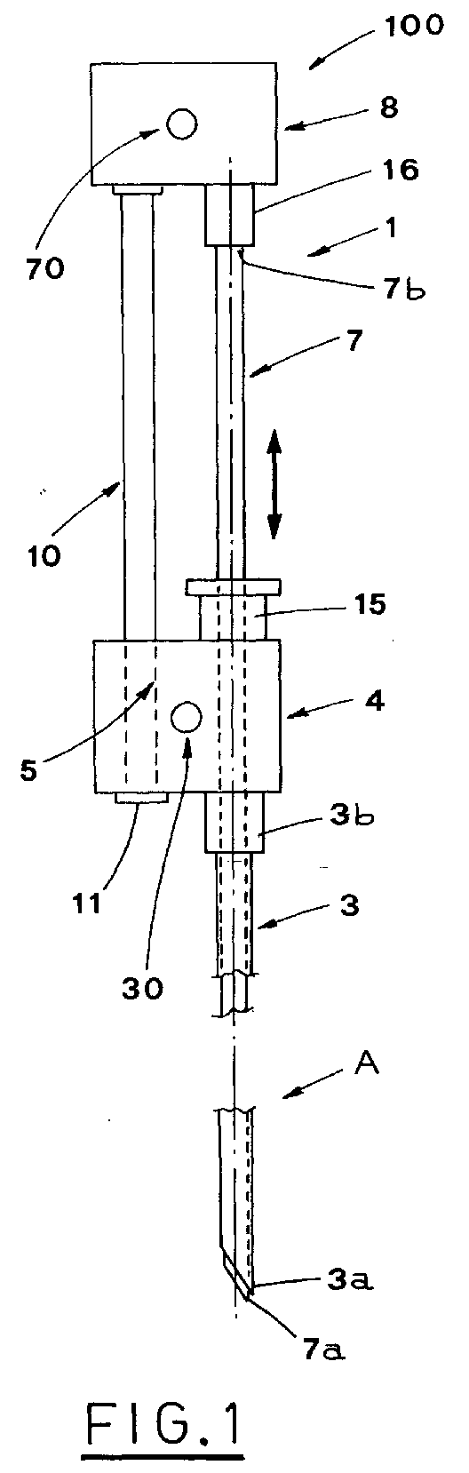
- the reference numeral 100 indicates herein a needle for taking bioptic samples according to a first embodiment of the invention, including a cannula 3 and a plunger 7.
- the cannula 3 is internally hollow and the plunger 7 is slidably inserted therein, moving between a rear position A ( Figure 1) and a fore position B ( Figure 2).
- the biopsy needle 100 is especially aimed at being used with known automatic snap-operated devices for taking samples, whose functionality are widely known and consequently, they will not be described in detail.
- the rear position A defines the correct position for the introduction of the needle 100 in the automatic device, when the latter is in its position ready to be snap-operated.
- the dimensions of the plunger 7 allow the sharp end 7a thereof to protrude slightly from the distal end 3a of the cannula 3, when the plunger 7 is in the above rear position A, while its proximal end 7b is set at a distance from the proximal end 3b of the cannula 3.
- the proximal ends 3b, 7b are in close position, while a distal portion of the plunger 7 protrudes from the above distal end 3a.
- the distal portion of the plunger 7 features, made therein, a lateral cavity 9, aimed at receiving the bioptic sample to be taken.
- the cannula 3 and the plunger 7 are also equipped, at their proximal ends 3b, 7b, with a related head 4, for the cannula, and a related head 8 for the plunger, respectively.
- the heads are equipped with coupling means 30, 70, which allow their coupling with the corresponding device for automatic sampling.
- the coupling means 30, 70 include substantially an equal number of holes having predetermined diameter, aimed at engaging with corresponding pins made in the automatic device.
- the coupling means 30, 70 can include characteristic conformations of the cannula head 4 and the plunger head 8, or other known coupling configurations.
- Guiding means 10 are fastened to the plunger head 8 and include a shaft having a substantially cylindrical section, which extends toward the sharp end 7a of the plunger 7, parallel thereto and at a predetermined distance therefrom.
- the shaft 10 is also engaged slidably with a longitudinal seat 5, which includes a through hole made in the cannula head 4 parallel to the cannula 3, to guide and limit the stroke of the plunger 7 inside the cannula 3.
- the length of the shaft 10 allows the plunger 3 to perform the whole stroke between the above mentioned rear position A and fore position B.
- the shaft 10 has an enlargement 11 whose section is bigger than the section of the above mentioned longitudinal hole 5.
- the enlargement 11 is aimed at preventing the shaft 10 from going out from the above mentioned longitudinal hole 5 and defines precisely the rear position A of the plunger 3, which, as it has been already said, corresponds to the correct position of introduction of the needle 100 into the automatic sampling device.
- the cannula head 4 features, on the side opposite to the one from which the cannula 3 protrudes as its prolongation, a substantially cylindrical and hollow inside seat 15.
- the seat 15 is aimed at receiving slidably the plunger 7 and at receiving a corresponding protrusion 16, situated between the proximal end 7b of the plunger 7 and the plunger head 8, so as to act as abutment between the latter and the cannula head 4.
- the operator who is to take a bioptic sample, brings the compound needle to the rear position A ( Figure 1), by withdrawing the plunger 7 from the cannula 3 until the cannula head 8 goes in abutment against the enlargement 11 of the shaft 10.
- the operator can easily maintain the above position by gripping the needle 100 between the thumb and forefinger in the region corresponding to the cannula head 8, taking care to grip also the shaft 10 and the part of the plunger 7 parallel thereto.
- the operator can introduce the needle, with its components in the correct position, into the patient's body until the operation position is reached.
- the operator introduces the needle 100 into the snap-operated sampling device and he/she can start the bioptic sample taking operation.
- the sampling device can perform the operation with known operation sequence, which usually includes a first step, during which the plunger 7 forwards up to the fore position B ( Figure 2) and subsequently the cannula 3 moves quickly forward, until the needle is brought back to the position A.
- the last step allows separation of a portion of tissue contained in the longitudinal cavity 9 of the plunger 7, and then to take it out of the patient's body for subsequent analysis.
- Figure 3 shows a second embodiment of the compound needle 100 according to the invention.
- guiding means 10a include a rigid thread, preferably metallic, folded like "U” and extending longitudinally and parallel to the cannula 3 and the needle 7.
- the ends of the rigid thread 10a are fastened to the plunger head 8.
- guiding means 5a which include a pair of longitudinal grooves, made laterally in the cannula head 4 and aimed at receiving slidably the opposite runs of the above mentioned rigid thread 10a.
- the above described compound needle 100 can be correctly positioned during the manual step of the bioptic sampling, in a simple and cheap way, and with use of not cumbersome elements, allowing the operator to grip safely the group cannula-plunger during this step.
- the position of introduction of the group cannula-plunger into the relative device for automatic sampling is defined precisely.
Landscapes
- Health & Medical Sciences (AREA)
- Life Sciences & Earth Sciences (AREA)
- Surgery (AREA)
- Animal Behavior & Ethology (AREA)
- Biomedical Technology (AREA)
- Heart & Thoracic Surgery (AREA)
- Medical Informatics (AREA)
- Molecular Biology (AREA)
- Pathology (AREA)
- Engineering & Computer Science (AREA)
- General Health & Medical Sciences (AREA)
- Public Health (AREA)
- Veterinary Medicine (AREA)
- Sampling And Sample Adjustment (AREA)
- Measurement Of The Respiration, Hearing Ability, Form, And Blood Characteristics Of Living Organisms (AREA)
- Infusion, Injection, And Reservoir Apparatuses (AREA)
Abstract
Description
- Figure 1 is a view of a compound needle obtained according to the present invention, in an introduction position;
- Figure 2 is a view of the needle of Figure 1 with the distal portion of the plunger in an extraction position;
- Figure 3 is a view of a compound needle according to another embodiment.
Claims (6)
- Compound needle for bioptic sampling, the needle including a hollow cannula (3) and a plunger (7), aimed at being introduced slidingly into said cannula (3), and provided, at its distal portion, with a lateral cavity (9) aimed at receiving a bioptic sample to be taken, said cannula (3) and plunger (7) being also provided, at their respective proximal ends (3b,7b), with relative heads, a cannula head (4) and a plunger head (8), respectively, said compound needle (100) being characterized in that it includes guiding means (10,10), which extend for a predetermined length from the plunger head (8), parallel to said plunger (7) and toward said distal portion thereof, said guiding means (10a) also slidingly engaging at least one longitudinal seat (5,5a) made in said cannula head (4) parallel to said cannula (3), so as to guide and limit the stroke of said plunger (7) inside the cannula.
- Compound needle, according to claim 1, characterized in that said guiding means (10) include a shaft having a predetermined length and in that said longitudinal seat (5) includes a through hole made in said cannula head (4).
- Compound needle, according to claim 2, characterized in that said shaft (10) and through hole (5) have circular section.
- Compound needle, according to claim 1, characterized in that said guiding means (10a) include a "U"-like rigid thread with ends fastened to said plunger head (8), and in that said longitudinal seat (5a) includes a pair of grooves made laterally in said cannula head (4) and aimed at receiving slidably the opposite runs of said rigid thread (10a).
- Compound needle, according to claims 2 or 4, characterized in that said shaft (10) includes, at its distal end, locking means (11) aimed at preventing the cannula head (4) from going out from said shaft (10).
- Compound needle, according to claim 5, characterized in that said locking means (11) include added material forming an enlargement having section bigger than the section of said longitudinal hole (5).
Applications Claiming Priority (2)
| Application Number | Priority Date | Filing Date | Title |
|---|---|---|---|
| ITBO20010531 | 2001-09-07 | ||
| IT2001BO000531A ITBO20010531A1 (en) | 2001-09-07 | 2001-09-07 | NEEDLE COMPOUND FOR BIOPTIC SAMPLES COLLECTION |
Publications (2)
| Publication Number | Publication Date |
|---|---|
| EP1290978A2 true EP1290978A2 (en) | 2003-03-12 |
| EP1290978A3 EP1290978A3 (en) | 2004-02-11 |
Family
ID=11439576
Family Applications (1)
| Application Number | Title | Priority Date | Filing Date |
|---|---|---|---|
| EP02020026A Withdrawn EP1290978A3 (en) | 2001-09-07 | 2002-09-06 | Needle set for biopsy |
Country Status (2)
| Country | Link |
|---|---|
| EP (1) | EP1290978A3 (en) |
| IT (1) | ITBO20010531A1 (en) |
Cited By (2)
| Publication number | Priority date | Publication date | Assignee | Title |
|---|---|---|---|---|
| WO2006111880A3 (en) * | 2005-04-20 | 2007-02-15 | Suros Surgical Systems Inc | Surgical adapter |
| US7658718B2 (en) * | 2002-05-31 | 2010-02-09 | Promex Technologies, Llc | Biopsy needle with integrated guide pin |
Family Cites Families (6)
| Publication number | Priority date | Publication date | Assignee | Title |
|---|---|---|---|---|
| GB1255330A (en) * | 1968-12-27 | 1971-12-01 | Baxter Laboratories Inc | Biopsy instrument |
| US5031634A (en) * | 1990-01-19 | 1991-07-16 | Beth Israel Hospital Assoc., Inc. | Adjustable biopsy needle-guide device |
| US5121751A (en) * | 1990-03-16 | 1992-06-16 | Ryder International Corporation | Instrument for tissue sampling |
| EP0540846B1 (en) * | 1991-09-27 | 1996-05-15 | Dlp, Inc. | Biopsy needle with spacer |
| US5236334A (en) * | 1991-12-16 | 1993-08-17 | Bennett Lavon L | Core biopsy needle units for use with automated biopsy guns |
| IT1287512B1 (en) * | 1996-12-11 | 1998-08-06 | Angela Martone | NEEDLE FOR BIOPSY |
-
2001
- 2001-09-07 IT IT2001BO000531A patent/ITBO20010531A1/en unknown
-
2002
- 2002-09-06 EP EP02020026A patent/EP1290978A3/en not_active Withdrawn
Cited By (3)
| Publication number | Priority date | Publication date | Assignee | Title |
|---|---|---|---|---|
| US7658718B2 (en) * | 2002-05-31 | 2010-02-09 | Promex Technologies, Llc | Biopsy needle with integrated guide pin |
| US8167819B2 (en) | 2002-05-31 | 2012-05-01 | Promex Technologies, Llc | Biopsy needle with integrated guide pin |
| WO2006111880A3 (en) * | 2005-04-20 | 2007-02-15 | Suros Surgical Systems Inc | Surgical adapter |
Also Published As
| Publication number | Publication date |
|---|---|
| ITBO20010531A0 (en) | 2001-09-07 |
| EP1290978A3 (en) | 2004-02-11 |
| ITBO20010531A1 (en) | 2003-03-07 |
Similar Documents
| Publication | Publication Date | Title |
|---|---|---|
| US4702261A (en) | Biopsy device and method | |
| US8439846B2 (en) | Bone biopsy device | |
| USRE38776E1 (en) | Surgical biopsy instrument | |
| EP1135065B1 (en) | Biopsy needle and surgical instrument | |
| US5183054A (en) | Actuated biopsy cutting needle with removable stylet | |
| US5560373A (en) | Needle core biopsy instrument with durable or disposable cannula assembly | |
| US5385151A (en) | Coaxial bone marrow biopsy needle assembly | |
| US5127419A (en) | Biopsy instrument with slotted driving member | |
| US8414602B2 (en) | Biopsy devices and methods | |
| US5511556A (en) | Needle core biopsy instrument | |
| JP4081557B2 (en) | Endoscopic multiple specimen biopsy forceps | |
| US8419687B2 (en) | Device for shielding a sharp tip of a cannula and method of using the same | |
| US7063672B2 (en) | Integrated biopsy needle assembly | |
| EP0318447A1 (en) | Driving unit for sampling devices | |
| JPH0463692B2 (en) | ||
| KR20030026248A (en) | Multiple-use biopsy apparatus and corresponding single-use biopsy instrument | |
| CN108095774B (en) | Improved bone biopsy device | |
| CN110461245A (en) | cutting biopsy instruments | |
| EP1290978A2 (en) | Needle set for biopsy | |
| EP1848342B1 (en) | Biopsy device | |
| EP1527739A2 (en) | Removable cannula instrument for taking biopsy samples | |
| JPS62207444A (en) | Biopsy instrument | |
| HK1093928A (en) | Device for shielding a sharp tip of a cannula and method of using the same |
Legal Events
| Date | Code | Title | Description |
|---|---|---|---|
| PUAI | Public reference made under article 153(3) epc to a published international application that has entered the european phase |
Free format text: ORIGINAL CODE: 0009012 |
|
| AK | Designated contracting states |
Kind code of ref document: A2 Designated state(s): AT BE BG CH CY CZ DE DK EE ES FI FR GB GR IE IT LI LU MC NL PT SE SK TR Designated state(s): AT BE BG CH CY CZ DE DK EE ES FI FR GB GR IE IT LI LU MC NL PT SE SK TR |
|
| AX | Request for extension of the european patent |
Extension state: AL LT LV MK RO SI |
|
| PUAL | Search report despatched |
Free format text: ORIGINAL CODE: 0009013 |
|
| AK | Designated contracting states |
Kind code of ref document: A3 Designated state(s): AT BE BG CH CY CZ DE DK EE ES FI FR GB GR IE IT LI LU MC NL PT SE SK TR |
|
| AX | Request for extension of the european patent |
Extension state: AL LT LV MK RO SI |
|
| AKX | Designation fees paid | ||
| REG | Reference to a national code |
Ref country code: DE Ref legal event code: 8566 |
|
| STAA | Information on the status of an ep patent application or granted ep patent |
Free format text: STATUS: THE APPLICATION IS DEEMED TO BE WITHDRAWN |
|
| 18D | Application deemed to be withdrawn |
Effective date: 20040812 |