EP1237173B1 - Miniature fuse of surface-mount type - Google Patents
Miniature fuse of surface-mount type Download PDFInfo
- Publication number
- EP1237173B1 EP1237173B1 EP02003339A EP02003339A EP1237173B1 EP 1237173 B1 EP1237173 B1 EP 1237173B1 EP 02003339 A EP02003339 A EP 02003339A EP 02003339 A EP02003339 A EP 02003339A EP 1237173 B1 EP1237173 B1 EP 1237173B1
- Authority
- EP
- European Patent Office
- Prior art keywords
- main body
- end portions
- fusible member
- mount type
- portions
- Prior art date
- Legal status (The legal status is an assumption and is not a legal conclusion. Google has not performed a legal analysis and makes no representation as to the accuracy of the status listed.)
- Expired - Lifetime
Links
Images


Classifications
-
- H—ELECTRICITY
- H01—ELECTRIC ELEMENTS
- H01H—ELECTRIC SWITCHES; RELAYS; SELECTORS; EMERGENCY PROTECTIVE DEVICES
- H01H85/00—Protective devices in which the current flows through a part of fusible material and this current is interrupted by displacement of the fusible material when this current becomes excessive
- H01H85/02—Details
- H01H85/04—Fuses, i.e. expendable parts of the protective device, e.g. cartridges
- H01H85/05—Component parts thereof
- H01H85/143—Electrical contacts; Fastening fusible members to such contacts
- H01H85/157—Ferrule-end contacts
-
- H—ELECTRICITY
- H01—ELECTRIC ELEMENTS
- H01H—ELECTRIC SWITCHES; RELAYS; SELECTORS; EMERGENCY PROTECTIVE DEVICES
- H01H85/00—Protective devices in which the current flows through a part of fusible material and this current is interrupted by displacement of the fusible material when this current becomes excessive
- H01H85/02—Details
- H01H85/04—Fuses, i.e. expendable parts of the protective device, e.g. cartridges
- H01H85/041—Fuses, i.e. expendable parts of the protective device, e.g. cartridges characterised by the type
- H01H85/0411—Miniature fuses
- H01H85/0415—Miniature fuses cartridge type
- H01H85/0418—Miniature fuses cartridge type with ferrule type end contacts
-
- H—ELECTRICITY
- H01—ELECTRIC ELEMENTS
- H01H—ELECTRIC SWITCHES; RELAYS; SELECTORS; EMERGENCY PROTECTIVE DEVICES
- H01H85/00—Protective devices in which the current flows through a part of fusible material and this current is interrupted by displacement of the fusible material when this current becomes excessive
- H01H85/02—Details
- H01H85/04—Fuses, i.e. expendable parts of the protective device, e.g. cartridges
- H01H85/05—Component parts thereof
- H01H85/055—Fusible members
- H01H85/06—Fusible members characterised by the fusible material
-
- H—ELECTRICITY
- H01—ELECTRIC ELEMENTS
- H01H—ELECTRIC SWITCHES; RELAYS; SELECTORS; EMERGENCY PROTECTIVE DEVICES
- H01H85/00—Protective devices in which the current flows through a part of fusible material and this current is interrupted by displacement of the fusible material when this current becomes excessive
- H01H85/02—Details
- H01H85/04—Fuses, i.e. expendable parts of the protective device, e.g. cartridges
- H01H85/05—Component parts thereof
- H01H85/165—Casings
- H01H85/175—Casings characterised by the casing shape or form
- H01H85/1755—Casings characterised by the casing shape or form composite casing
-
- H—ELECTRICITY
- H01—ELECTRIC ELEMENTS
- H01H—ELECTRIC SWITCHES; RELAYS; SELECTORS; EMERGENCY PROTECTIVE DEVICES
- H01H85/00—Protective devices in which the current flows through a part of fusible material and this current is interrupted by displacement of the fusible material when this current becomes excessive
- H01H85/02—Details
- H01H85/04—Fuses, i.e. expendable parts of the protective device, e.g. cartridges
- H01H85/05—Component parts thereof
- H01H85/18—Casing fillings, e.g. powder
- H01H85/185—Insulating members for supporting fusible elements inside a casing, e.g. for helically wound fusible elements
-
- H—ELECTRICITY
- H01—ELECTRIC ELEMENTS
- H01H—ELECTRIC SWITCHES; RELAYS; SELECTORS; EMERGENCY PROTECTIVE DEVICES
- H01H85/00—Protective devices in which the current flows through a part of fusible material and this current is interrupted by displacement of the fusible material when this current becomes excessive
- H01H85/02—Details
- H01H85/04—Fuses, i.e. expendable parts of the protective device, e.g. cartridges
- H01H85/041—Fuses, i.e. expendable parts of the protective device, e.g. cartridges characterised by the type
- H01H85/0411—Miniature fuses
- H01H2085/0414—Surface mounted fuses
Definitions
- the present invention relates to a miniature fuse of surface mount type as defined by the features of the preamble portion of claim 1.
- the present invention is suitable for a micro-miniature fuse of surface mount type which can be used for protection of apparatuses for communication and whose longitudinal length does not exceed 11 mm.
- Apparatuses for communication to be connected to telephone lines and the like are liable to be subjected to high surge current due to indirect lightning strikes, or sudden and unusually high increases in voltage due to telephone lines accidentally coming into contact with power lines.
- fuses to be used for apparatuses for communication require both a strong time lag characteristic preventing the fuses from being melted by the surge current due to indirect lightning strikes as well as a high breaking capacity in the order of 60A at AC600V which assures a big fault current flow at the moment of the accidental power line contact to be safely switched off.
- micro-miniature sized fuses are required to have a strong time lag characteristic and a high breaking capacity; they are also required to be of a surface mount type so that surface mounting of high density may be carried out.
- inner soldered fuses which are constructed in such a manner as shown in Fig. 1 and Fig. 2, wherein a fusible member 102 is wound around a support member of insulating material made up of bundled glass fibers and the respective ends of the fusible member 102 are soldered to the recessed bottom of the conductive terminals 104 of cap-like configuration.
- a disadvantage of the inner soldered type fuse is that the electrical resistances of produced fuses disperse widely from designed value so that the pre-arcing time may often be uneven.
- an inner soldering type when a soldering iron is placed from the outside of the cap-like terminal 104 so as to melt the solder 106 attached to the interior of the recess of the cap terminal 104 to solder the fusible member 102 wound around the bundled glass fibers 100 to the bottom of the recess of the cap terminal 104, melted soldering material will be caused to flow along the fusible member 102 wound around the bundle of the glass fibers 100, resulting in a clogging of the spaces between the adjacent portions of the wound fusible member 102 to make short-circuits between them.
- the length of the fusible member 102 which is in the short-circuit state may result in one-third of overall length of the fusible member, and thus the performance of fuses may be changed entirely.
- the conductive cap-like terminals 104 and the main body 108 made of an insulating material are secured by the frictional force caused by coagulation of the soldering material which has flowed into the space between the cap terminals and the main body.
- the fuses are also heated to a temperature of soldering.
- soldering temperature profiles differ from manufacturer to manufacturer, in the case of high temperature soldering, the soldering materials within the fuses, namely the soldering materials which have entered between the conductive cap-like terminals 104 and the main body 108 are caused to melt, whereby the conductive cap-like terminals 104 might possibly be detached from the main body 108, which was considered a problem. Furthermore, since the melting point of the soldering material which does not contain lead in view of problems associated with its use tends to be relatively high, the soldering temperature at the time of mounting fuses on a substrate is likely to be further increased, which is another problem that will have to be solved.
- the main body 108 has a columnar configuration and a through hole 110 is so provided as to extend between the opposite end faces of the main body in the longitudinal direction. Since a miniature fuse of surface mount type is so small, in the order of 11 mm in respect of the overall length, the diameter of such a through hole is also very small, in the order of mm. Accordingly, since the support member 100 with the fusible member 102 wound therearound had to be inserted through a small inlet on the end face of the main body 108, workability in the course of manufacturing was consequently poor.
- US-A-4 646 043 discloses a miniature fuse with the features of the preamble portion of claim 1.
- This prior art fillerless electric fuse has a tubular casing with open ends and a fusible element in the form of wire extending from one of the open ends to the other.
- the casing is provided with a pair of annular sections of reduced diameter at opposite ends thereof which receive a pair of metal contact rings having an outside diameter substantially the same as the outside diameter of the fusè casing.
- the fusible element extends through each of the open ends of the casing and is welded into electrically conductive relationship with the axially outwardly facing surfaces of the respective metal contact rings.
- End terminals in the form of caps are press fitted over each of the metal contact rings and are permanently secured to the fuse casing in that free ends of the caps are rolled or crimped into annular grooves formed in the outer peripheral surface of the tubular casing.
- the miniature fuse should provide a stable pre-arcing time-current characteristic without uneven performance and a strong time lag characteristic and, in addition, a large braking capacity.
- the electrical and mechanical connection is executed by welding so that the pre-arcing time-current characteristic can be kept stable and a strong time lag characteristic can be provided and a high breaking capacity in the order of 60A at AC 600V without sustaining arcs due to metallic vaporization of the soldering materials can be attained.
- the conductive terminals and the fusible member are connected by welding, a steady pre-arcing time-current characteristic and a large breaking capacity can be attained without uneven performance, and the miniature fuse of surface mount type may not be affected by the heat generated at the time of soldering the miniature fuse of surface mount type to a printed circuit board after assembly, whereby stable connection between them can be maintained at the time of mounting the fuse to the printed circuit board.
- the main body is comprised of two split members which are separated in the main body longitudinal direction, and recessed portions extending to the split end surface are provided, as the recessed portions of said main body, in the vicinities of the respective end portions of the side surfaces of at least one of said split members forming the columnar configuration of the main body, such a construction as having a recessed portion at the side surface of the main body can be manufactured by press molding and the fusing member can be extended in a casing of a fuse easily, whereby production of miniature fuse of surface mount type can be made easy, automated production can also be facilitated and production rate can be enhanced.
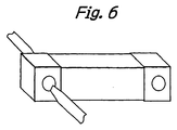
- the main body 10 is made of heat resistant insulating material and has a columnar configuration and is provided with a through-hole extending through the main body between the opposite end faces 11 in the longitudinal direction. While the fusible member 30 is extended through the through-hole, the middle part of the fusible member 30 is wound spirally around the support member 40 and the respective end portions of the fusible member 30 are bent along the end faces 11 of the main body and engaged with the outer peripheral surface of the end portions 12 of the main body 10.
- the conductive terminals 20 having a cap-like configuration provided with recessed portion of which sectional shape is substantially identical with that of the end portions 11 so that the terminals may be fit onto the opposite end portions 12 of the main body 10. With the conductive terminals 20 thus fit onto the main body 10, the terminals 20 of cap-like configuration and the fusible members 30 are electrically connected to each other by welding.
- composition of the material of the support member having high thermal conductivity coefficient in terms of weight ratio, Al 2 O 3 exceeding 96%, MgO exceeding 3% and BeO less than 1% are contained.
- the fusible member having a low melting temperature is wound around the support member, the fusible member being made of material containing in terms of weight ratio Ag equal to or exceeding 50%, Cu equal to or exceeding 20%, Zn equal to or exceeding 17% and Sn equal to or exceeding 5%.
- Thin lids made of sheet of insulating material having a thickness smaller than the depth of the conductive terminal 20 of cap-like configuration having a substantially identical shape to that of the bottom face of the conductive terminals 20 may be disposed between the end surface 11 of the main body 10 and the bottom face of the terminals 20 of cap-like configuration.
- the respective end portions of the fusible member 30 which is extended inside of the main body 10 along the diagonal line are bent along the opposite end surfaces of the main body and engaged with the outer peripheral surface of the end portions 12.
- the terminals 20 of cap-like configuration are fit onto the opposite end portions 12 of the main body 10 and, as shown in Fig. 6, the opposite side surfaces of the terminals 20 of cap-like configuration are welded and fixed.
- the support member having a higher thermal conductivity coefficient is caused to radiate the Joule heat generated due to flow of current through the fusible member 30 out of the fuse through the terminals 20 of cap-like configuration at the opposite ends, thereby preventing the temperature of the metal having a low melting temperature from rising and providing a strong time lag characteristic.
- the fuse according to the present invention can have a high breaking capacity such as AC 600V at 60A.
- Fig. 3 is the perspective view illustrating an example similar to the invention while Fig. 4 is the sectional view taken along the line A-A in Fig. 3.
- cut-out recessed portions 13 are formed on the outer peripheral surface of the opposite end portions 12 of the main body 10 of a columnar configuration made of heat resistant insulating material in contact with the end surfaces 11 of the main body 10.
- the middle part of the fusible member 30 which is extended inside the main body along the diagonal line is wound spirally around the support member 40 and the respective end portions of the fusible member 30 are engaged with the cut-out recessed portions 13.
- the opposite side surfaces of the terminals 20 of cap-like configuration in parallel with the outer peripheral surface of the main body 10 on which the cut-out recessed portions 13 with the end portions of the fusible member 30 engaged therewith are welded with the welding electrodes held in such a manner as to sandwich the side surfaces, thereby providing the fuse of the present invention which does not exceed a length of 11 mm.
- the fusible member 30, the terminals 20 of cap-like configuration and the main body 10 are electrically and mechanically connected by welding without use of soldering, whereby the pre-arcing time-current performance of the fuse becomes stable and a strong time lag characteristic and a high breaking performance as 60A at AC 600V can be attained without metallic vaporization of the soldering material and sustaining arcs.
- FIG. 7 is the exploded assembly drawing of the miniature fuse of surface mount type according to the embodiment.
- Fig. 8 is the longitudinal sectional view of the miniature fuse of surface mount type according to the second embodiment viewed in the direction of side surface.
- Fig. 9 is the longitudinal sectional view of the miniature fuse of surface mount type according to the second embodiment in the direction of upper surface.
- reference numeral 50 designates a rectangular split casing of ceramic material forming the main body of the miniature fuse of surface mount type.
- the rectangular split casing 50 of ceramic material consists of the upper ceramic casing 52 and the lower ceramic casing 54.
- Reference numeral 56 designates the cap serving as the conductive terminal having a recessed portion having the sectional shape substantially identical to that of the opposite end portions of the casing 50 so as to be fit onto the opposite end portions of the rectangular ceramic split casing 50.
- Reference numeral 58 designates the ceramic rod adapted to support the elongated fusible member 60.
- the ceramic material to be used for the rectangular split casing 50 may be those ceramic materials which may be generally used for miniature fuses of surface mount type. According to the invention, the material to be used for the rectangular ceramic split casing 50 is not limited to ceramic material, and any heat resistant insulating material which may be press molded such as thermosetting resin and the like, may be applied.
- the cap 56 is made of basic material composed of copper or brass and then plated with tin, nickel or silver.
- the material of the cap 56 is not limited to those materials as mentioned above, and any material may be utilized so long as welding with the fusible member 60, as explained later, and connection with the connection lands and the like on a printed circuit board after completion of the fuse production process are feasible. Furthermore, surface treatment of the basic material is not limited to plating and any treatment other than plating may be applied.
- the ceramic rod 58 is preferably made of ceramic material containing a composition having a high thermal conductivity coefficient as mentioned above and containing in terms of weight ratio Al 2 O 3 exceeding 96%, MgO exceeding 3% and BeO less than 1%.
- the fusible member 60 is preferably composed of metal having a low melting temperature containing in terms of weight ratio Ag equal to or exceeding 50%, Cu equal to or exceeding 20%, Zn equal to or exceeding 17% and Sn equal to or exceeding 5%.
- the present invention is not limited to this material and it may contain other metals.
- the rectangular split type casing 50 is constructed by upper ceramic casing 52 and the lower ceramic casing 54 which are substantially equally divided at the longitudinal direction of the rectangular column.
- the upper ceramic casing 52 and the lower ceramic casing 54 are respectively provided with recesses 62 and 64 at the opposite sides to be matched so that a cavity may be formed inside of the casing when they are jointed.
- a projection 66 is provided as shown in Fig.
- joint end surface at the end surface to be joined (this end surface hereinafter referred to as "joint end surface") of the upper ceramic casing 52 while a recess 68 to be fit in the projection 66 of the upper ceramic casing 52 is provided at the joint end surface of the upper ceramic casing 54 as shown in Fig. 7 so that when the upper ceramic casing 52 and the lower ceramic casing 54 are jointed, they are accurately jointed without sliding laterally.
- the projection 66 and the recess 68 may be entirely along the end surfaces or partially along the end surfaces. As shown in Fig. 7 and Fig.
- cut-out portions 70 of semi-circular shape for leading out one end of the fusible member 60 are respectively provided at the joint end surfaces on one side surface of one end portion of the upper ceramic casing 52 and the lower ceramic casing 54 while cut-out portions 70 are provided at the joint end surfaces on the other side surface opposite to the one side surface of the other end portion of the upper ceramic casing 52 and the lower ceramic casing 54.
- recessed portions 72 which constitute one integral recessed portion when both upper and lower casings are joined are provided at the opposite side surfaces of the respective end portions of the upper ceramic casing 52 and the lower ceramic casing 54 to extend to the joint end surfaces. It is to be noted that the recessed portion 72 shown in Fig.
- recessed portions 72 extends along the upper surface and the lower surface of the upper and the lower ceramic casings so as to facilitate press molding. Even if they extend along the upper and lower surfaces halfway, press molding may be performed, so this variation is also included in the scope of the present invention.
- the purpose of these recessed portions 72 is to enable the cap 56 to be fixed to the rectangular split type casing 50 of ceramic material. The manner of fixing by use of these recessed portions will be explained later.
- the rectangular ceramic casing 50 is not of a split type but one piece unit, one complete recessed portion as mentioned above can not be manufactured by press molding, and subsequent to molding, additional time-consuming and costly processes such as grinding and the like may be required. According to the present invention, however, owing to the split type, when the upper and the lower ceramic casings 52 and 54 are molded, the recessed portions can be easily manufactured simultaneously.
- the fusible member 60 and the ceramic rod 58 in the condition shown in Fig. 10 can be easily placed on the recessed portion 64 of the lower ceramic casing 54 from above. Then, the tip end 76 of the fusible member 60 is passed through the cut-out portion 70 to be pulled outwardly from the lower ceramic casing 54 and, as shown in detail in the enlarged view A in Fig. 9, the tip end is bent along the face of the recessed portion 72 to be oppositely engaged with the recessed portion 72 so that they face each other.
- productivity can be enhanced owing to the split type casings.
- the upper ceramic casing 52 is laid on the lower ceramic casing 54 and the caps 56 are fit onto the opposite end portions of the rectangular ceramic casing 50 of split type.
- Fig. 11 is the schematic view showing the process of welding.
- reference numeral 90 designates a pair of welding electrodes.
- the cap 56 is sandwiched by a pair of the electrodes 90 as shown in Fig. 11. Under this condition, the electric current is caused to flow between the electrodes with the cap being pressed. As the consequence, the cap generates heat whereby the cap 56 and the end portion 76 of the fusible member 60 are welded.
- projections 74 are formed at the cap 56 so as to fit into the recessed portions 72 of the rectangular ceramic casing 50 of split type as shown in Fig. 11, whereby the cap 56 can be secured to the rectangular ceramic casing 50 of split type.
- the portion designated by the reference numeral 74 when viewed from outside of the cap 56, appears to be recessed; however, when viewed from inside of the cap, the portion to be fit with the recessed portion 72 appears to be projected; therefore, this portion is referred to as projection.
- the fusible member 60 and the cap 56 are joined by welding, the distance between the terminals of the fusible member 60 can be kept constant without variation caused during assembly, resulting in a stable pre-arcing time-current characteristic. Since the fusing member 60 and the cap 56 are jointed to each other by way of their basic metals, they are not affected by the heat generated at the time of soldering the miniature fuses of surface mount type to the substrates after assembly, whereby stable connection of the fusible member 60 and the cap 56 can be maintained at the time of mounting to the substrates.
- the rectangular ceramic casing 50 of split type and the cap 56 are heated and pressurized so as to deform the cap 56 to form the projection 74 of the cap 56, and then the recessed portions 74 are fit into the recessed portions 72 of the rectangular ceramic casing 50 of split type.
- the rectangular ceramic casing 50 of split type and the cap 56 are secured without use of metals having a low melting temperature such as soldering material. Accordingly, the cap 56 will not be detached from the rectangular ceramic casing 50 of split type due to the heat generated at the time of soldering the miniature fuse of surface mount type to the substrate after assembly.
- jointing of the cap 56 and the fusible member 60 and fixing of the cap 56 and the rectangular ceramic casing 50 of split type can be attained in one process. Since the caps 56 are inserted into the opposite ends of the casing with the upper and lower ceramic casings 52, 54 of split type being aligned, they may not be disassembled under a normal condition of use without applying adhesive and the like. Furthermore, since the caps 56 are caused to deform in conformity with the recessed portions 72 formed at the side surfaces of the rectangular ceramic casing 50 of split type, the rectangular ceramic casing 50 of split type and the caps 56 are fixed to each other reliably without disassembling the miniature fuses of surface mount type under a normal condition of use. Thus, the production processes can be simplified and the production costs can be reduced.
- recessed portions 72 are provided at both the upper and the lower ceramic casing 52 and 54 according to the embodiment of the present invention, they may be provided at either of them.
- end walls 78 of ceramic material which have the same function as the lids according to the previous example. Accordingly, the cap can withstand high inner pressure at the time of breaking and is thus more rigid than the case of the inner side of the caps 56 being exposed directly to the interior cavity of the casing. Furthermore, since the end walls 78 are provided between the portion of the fusible member 60 existing inside the interior cavity and also in proximity to the caps 56, even if arcs are generated at the time of breaking, such arcs can be easily extinguished. As a consequence, the breaking capacity can be increased.
- Fig. 12 is the longitudinal sectional view of the miniature fuse of surface mount type utilizing such an construction of the fusible member including the support member being different from that of the embodiment in that the double wound wire construction is employed. For those parts of the construction which are the same as those of the embodiment, explanation is omitted. Only the differences will be explained. As shown in Fig. 12, the second fusible member 60b of wire form is wound around the first fusible member 60a of wire form.
- Two fusible members 60a and 60b of wire form thus wound are held in the recessed portion 64 of the lower ceramic casing 54 between the opposite cut-out portions 70 and the end portions 76' of two fusible members 60a and 60b of wire form thus wound are engaged with the side surfaces of the rectangular ceramic casing 50 of split type via the cut-out portions 70, and connected to the cap 56 by welding.
- the two fusible members of wire form may be twisted around each other, for example, or may be wound in any suitable way so long as they provide double wire winding construction.
- Fig. 13 is the longitudinal sectional view taken in the direction of the upper surface of the miniature fuse of surface mount type which employs single wire construction as the construction of the fusible member including the support member which is different from that of the embodiment.
- the fusible member 60 of a single wire is held in the recessed portion 64 of the lower ceramic casing 54 between the opposite cut-out portions 70, and the end portions 76 of the fusible member are engaged with the side surface of the rectangular ceramic casing 50 of split type and connected to the cap 56 by welding.
- Fig. 14 is the longitudinal sectional view taken in the direction of the upper surface of the variant of the embodiment shown in Fig. 13. It is seen that the cut-out portions 70 are not provided at the side surface of the end portion of the lower ceramic casing 54 but at the opposing end surfaces as shown in the drawing. The cut-out portions are also provided at the corresponding positions also at the upper ceramic casing 52 not shown.
- the recessed portions 72' to which the end portions 76 of the fusible member 60 are engaged extend to the end surfaces of the lower ceramic casing 54. It is preferable from the production point of view that same configuration of the recessed portion 72' is also applied to the upper ceramic casing 52 not shown.
- the recessed portion 72' should not necessarily extend to the end surface of the upper ceramic casing 52.
- the end portion 76 of the fusible member 60 is bent, having passed through the cut-out portion 70, and extended along the end surface of the lower ceramic casing 54. Then, it is bent at the corner of the end surface and extended along the face of the recessed portion 72' to the welded position and engaged.
- Figs. 15a to 15e illustrate examples of various positions and patterns of welding.
- Fig. 15a shows a case in which the welding positions are located only at the side surfaces in the same manner as the previous embodiment;
- Fig. 15b shows a case in which the clearance between the rectangular ceramic casing 50 of split type and the caps 56 are absorbed, and the welding positions are located both at the side surfaces and the upper and lower surfaces so as to put tightly together both of the split casings, namely, the upper and lower ceramic casings 52 and 54;
- Fig. 15a shows a case in which the welding positions are located only at the side surfaces in the same manner as the previous embodiment
- Fig. 15b shows a case in which the clearance between the rectangular ceramic casing 50 of split type and the caps 56 are absorbed, and the welding positions are located both at the side surfaces and the upper and lower surfaces so as to put tightly together both of the split casings, namely, the upper and lower ceramic casings 52 and 54;
- FIG. 15c shows a case in which the welding positions are only located at the side surfaces and the welding pattern is of double type so that the welded part of the fusible member may not collapse excessively in case the thickness of the fusible member being relatively large.
- Fig. 15d shows a case in which the welding patterns at the side surfaces are of double type but those at the upper and lower surfaces are the same as those in the case of Fig. 15b;
- Fig. 15e shows a case in which welding patterns both at the side and upper and lower surfaces are of double type in order to enable the electrode having a single type of tip end shape, as well as other reasons.
- reference numeral 80 designates welding traces.
- the welding traces provided at the caps at the locations corresponding to those of the recessed portions 72 (not shown in Figs. 15a to 15e) provided at the upper and lower ceramic casings 52, 54 are deformed to project so that they fit into the recessed portions 72 (see the recessed portions 72 and projections 74 shown in Fig. 9) whereby the caps 56 are fixed to the rectangular ceramic casing of split type in the same manner as that explained in the second embodiment of the present invention.
- Fig. 16 illustrates the configuration of the tip ends of the electrodes to be used for welding of double type as shown in Figs. 15c through 15e and the process of welding. It can be seen that the tip end of the electrode 90 is separated in two ways and with regard to the welding traces to be provided at the locations corresponding to the recessed portions 72(not shown) provided at the upper and lower ceramic casings 52, 54, two projections 74' to be fit into the recessed portions 72 will be formed at the time of welding.
- Fig. 17 illustrates an example of an aspect of the present invention for connecting the caps and the fusible members by welding being applied to the main body which has a through-hole and is a one-piece columnar construction made of heat resistant insulating material.
- the fusible member of a single wire is passed through the through-hole 84 of the main body 82, and the tip ends 76 of the fusible member 60 are bent along the end surfaces of the main body and engaged with the main body 82 along the side surfaces of the main body 82.
- the main body 82 may be made of ceramic material.
- the tip ends 76 of the fusible member 60 and the caps 56 are connected by welding in the same manner as that explained in the second embodiment of the present invention.
- both side surfaces and the upper and lower surfaces may be welded, for example, as shown in Figs. 15b, 15d and 15e.
- Fig. 18 illustrates an example of the miniature fuse of surface mount type which is cylindrical.
Landscapes
- Chemical & Material Sciences (AREA)
- Composite Materials (AREA)
- Fuses (AREA)
Description
Claims (4)
- A miniature fuse of surface mount type including:whereina fusible member (60;60a,60b),a main body (50) made of heat resistant insulating. material, anda pair of conductive terminals in the form of metallic caps (56),
said main body (50) has a columnar configuration defining a longitudinal direction, a pair of opposing end portions and a cavity defined inside of the main body (50) between said pair of end portions,
said fusible member (60;60a,60b) is disposed in said cavity of said main body (50) between said pair of end portions,
opposite end portions (76) of said fusible member (60;60a,60b) are extended outwardly onto the outer surface of said main body (50) from. the pair of end portions of said main body (50) or from vicinities thereof,
the respective metallic caps (56) are fit onto the respective end portions of said main body (50) and electrically connected to the respective end portions (76) of said fusible member (60;60a,60b), and
recessed portions (72;72') are provided in the vicinity of the respective end portions of the side surfaces of the columnar configuration of the main body (50);
characterized in that:said main body (50) is comprised of two split members (52,54) which are separated in the main body longitudinal direction;said recessed portions (72;72') are provided in the vicinity of the respective end portions of the side surfaces of at least one of said split members (52,54) forming the columnar configuration of the main body (50) and extend to the split end surface thereof;the end portions (76) of said fusible member (60;60a,60b) are connected to said caps (56) by welding, andprojections (74;74';80), formed at said caps (56) by said welding, are fit in the recessed portions (72;72') of said main body (50) in order to fix said caps (56) to said main body (50). - The miniature fuse of surface mount type according to claim 1, characterized in that:recessed portions (72;72') extending to the split end surfaces are also provided in the vicinity of the respective end portions of the side surfaces of the other of said split members (52,54) forming the columnar configuration of the main body (50); andthe recessed portions (72;72') of said two split members (52,54) form one recessed portion at the side surfaces forming the columnar configuration when said two split members are jointed to form said main body (50).
- The miniature fuse of surface mount type according to claim 1 or 2, characterized in that said main body (50) is made of ceramic material.
- The miniature fuse of surface mount type according to claim 1, 2 or 3, characterized in that said split members respectively comprise end walls (78) such that said caps (56) are not directly exposed to the interior of the cavity of the main body (50).
Applications Claiming Priority (4)
| Application Number | Priority Date | Filing Date | Title |
|---|---|---|---|
| JP2001039279 | 2001-02-16 | ||
| JP2001039279 | 2001-02-16 | ||
| JP2001370902 | 2001-12-05 | ||
| JP2001370902A JP3820143B2 (en) | 2001-02-16 | 2001-12-05 | Surface mount type small fuse |
Publications (3)
| Publication Number | Publication Date |
|---|---|
| EP1237173A2 EP1237173A2 (en) | 2002-09-04 |
| EP1237173A3 EP1237173A3 (en) | 2003-03-05 |
| EP1237173B1 true EP1237173B1 (en) | 2005-04-27 |
Family
ID=26609491
Family Applications (1)
| Application Number | Title | Priority Date | Filing Date |
|---|---|---|---|
| EP02003339A Expired - Lifetime EP1237173B1 (en) | 2001-02-16 | 2002-02-13 | Miniature fuse of surface-mount type |
Country Status (5)
| Country | Link |
|---|---|
| US (1) | US6798330B2 (en) |
| EP (1) | EP1237173B1 (en) |
| JP (1) | JP3820143B2 (en) |
| CA (1) | CA2371101C (en) |
| DE (1) | DE60203839T2 (en) |
Cited By (1)
| Publication number | Priority date | Publication date | Assignee | Title |
|---|---|---|---|---|
| WO2007145389A1 (en) * | 2006-06-16 | 2007-12-21 | Smart Electronics Inc. | Small-sized surface-mounted fuse and method of manufacturing the same |
Families Citing this family (37)
| Publication number | Priority date | Publication date | Assignee | Title |
|---|---|---|---|---|
| US7320171B2 (en) * | 2001-03-02 | 2008-01-22 | Wickmann-Werke Gmbh | Fuse component |
| EP1518447A1 (en) * | 2002-06-21 | 2005-03-30 | Continental Teves AG & Co. oHG | Printed board for electronic devices controlling a motor vehicle |
| US20050006923A1 (en) * | 2003-07-08 | 2005-01-13 | Johnson Controls Technology Company | Visor for a vehicle |
| US7436283B2 (en) * | 2003-11-20 | 2008-10-14 | Cooper Technologies Company | Mechanical reinforcement structure for fuses |
| US6992560B2 (en) * | 2004-05-13 | 2006-01-31 | Chun-Chang Yen | Fuse structure |
| KR100644412B1 (en) | 2004-11-16 | 2006-11-10 | 주식회사 세화전자 | Manufacturing method of ultra small smd fuse |
| US20060119465A1 (en) * | 2004-12-03 | 2006-06-08 | Dietsch G T | Fuse with expanding solder |
| US7477129B2 (en) | 2004-12-06 | 2009-01-13 | Cooper Technologies Company | Current limiting fuse |
| US7515031B2 (en) * | 2005-06-06 | 2009-04-07 | Cooper Technologies Company | Universal fuse engine with modular end fittings |
| DE102005033212B4 (en) * | 2005-06-07 | 2007-04-19 | Siba Fuses Gmbh & Co. Kg | High voltage fuse |
| US8154376B2 (en) * | 2007-09-17 | 2012-04-10 | Littelfuse, Inc. | Fuses with slotted fuse bodies |
| JP4348385B2 (en) * | 2007-09-20 | 2009-10-21 | 日本製線株式会社 | Surface-mount current fuse |
| US20090108980A1 (en) * | 2007-10-09 | 2009-04-30 | Littelfuse, Inc. | Fuse providing overcurrent and thermal protection |
| US8937524B2 (en) * | 2009-03-25 | 2015-01-20 | Littelfuse, Inc. | Solderless surface mount fuse |
| US8203420B2 (en) * | 2009-06-26 | 2012-06-19 | Cooper Technologies Company | Subminiature fuse with surface mount end caps and improved connectivity |
| US9117615B2 (en) * | 2010-05-17 | 2015-08-25 | Littlefuse, Inc. | Double wound fusible element and associated fuse |
| US9224564B2 (en) * | 2010-06-04 | 2015-12-29 | Littelfuse, Inc. | Fuse with counter-bore body |
| US8629750B2 (en) * | 2010-09-20 | 2014-01-14 | Cooper Technologies Company | Fractional amp fuse and bridge element assembly therefor |
| US9558905B2 (en) | 2011-10-27 | 2017-01-31 | Littelfuse, Inc. | Fuse with insulated plugs |
| US9202656B2 (en) * | 2011-10-27 | 2015-12-01 | Littelfuse, Inc. | Fuse with cavity block |
| US20140049936A1 (en) * | 2012-08-14 | 2014-02-20 | Mark Andre Faulkner | Electrical disconnect apparatus with fuse |
| JP6437239B2 (en) | 2013-08-28 | 2018-12-12 | デクセリアルズ株式会社 | Fuse element, fuse element |
| JP6214318B2 (en) * | 2013-10-09 | 2017-10-18 | デクセリアルズ株式会社 | Current fuse |
| CN104051202B (en) * | 2014-05-30 | 2016-06-29 | 安徽三和电力技术有限公司 | High and low voltage electric distribution system fuse |
| DE202015101840U1 (en) * | 2015-04-15 | 2015-04-30 | Inter Control Hermann Köhler Elektrik GmbH & Co. KG | Fuse component |
| US10276338B2 (en) | 2016-06-01 | 2019-04-30 | Littelfuse, Inc. | Hollow fuse body with trench |
| US10325744B2 (en) * | 2016-06-01 | 2019-06-18 | Littelfuse, Inc. | Hollow fuse body with notched ends |
| US11028835B2 (en) | 2016-12-08 | 2021-06-08 | Lintec Of America, Inc. | Artificial muscle actuators |
| US10483071B2 (en) * | 2018-01-05 | 2019-11-19 | Littelfuse, Inc. | Inner cap for high voltage fuse |
| US11393651B2 (en) * | 2018-05-23 | 2022-07-19 | Eaton Intelligent Power Limited | Fuse with stone sand matrix reinforcement |
| US10446354B1 (en) * | 2018-10-17 | 2019-10-15 | Littelfuse, Inc. | Coiled fusible element for high reliability fuse |
| US11101093B2 (en) * | 2019-01-21 | 2021-08-24 | Littelfuse, Inc. | Fuses and methods of forming fuses |
| DE102019128900A1 (en) * | 2019-10-25 | 2021-04-29 | Endress+Hauser SE+Co. KG | Method for producing an SMD-solderable component, SMD-solderable component, electronic unit and field device |
| CN110880442A (en) * | 2019-12-09 | 2020-03-13 | Aem科技(苏州)股份有限公司 | Surface-mounted fuse |
| CN111710574A (en) * | 2020-07-20 | 2020-09-25 | 上海瑞忒尔电气技术有限公司 | A fuse structure with low loop resistance and high reliability |
| CN112863970A (en) * | 2021-03-03 | 2021-05-28 | 东莞市博钺电子有限公司 | Paster fuse |
| US11804353B1 (en) * | 2022-07-26 | 2023-10-31 | Littelfuse, Inc. | Fuse body with notched ends |
Family Cites Families (19)
| Publication number | Priority date | Publication date | Assignee | Title |
|---|---|---|---|---|
| DE364719C (en) | 1922-11-30 | Josef Goette | Heavy current fuse with a hinge-like collapsible cartridge body divided into two halves along the length | |
| US1377398A (en) * | 1918-11-18 | 1921-05-10 | George A Conrad | Fuse-cartridge |
| US3460086A (en) * | 1967-09-25 | 1969-08-05 | Mc Graw Edison Co | Protectors for electric circuits |
| US3721936A (en) * | 1972-03-29 | 1973-03-20 | Chase Shawmut Co | Cartridge fuse having blown fuse indicator |
| JPS5842576B2 (en) | 1975-04-16 | 1983-09-20 | 三王産業株式会社 | Time lag fuse |
| JPS5293950A (en) | 1976-02-03 | 1977-08-08 | Sano Sangyo Kk | Time lag fuse |
| US4158187A (en) * | 1977-08-05 | 1979-06-12 | Gould Inc. | Means for affixing ferrules to a fuse casing |
| AT353882B (en) | 1978-02-03 | 1979-12-10 | Wickmann Werke Ag | MELT FUSE |
| US4656453A (en) * | 1982-12-09 | 1987-04-07 | Littelfuse, Inc. | Cartridge fuse with two arc-quenching end plugs |
| DE3342302A1 (en) * | 1983-11-23 | 1985-05-30 | Wickmann-Werke GmbH, 5810 Witten | METHOD FOR THE PRODUCTION OF A SMALL FUSE AND A SMALL FUSE |
| NL8501004A (en) * | 1985-04-04 | 1986-11-03 | Littelfuse Tracor | MELT SAFETY. |
| US4646053A (en) | 1985-12-30 | 1987-02-24 | Gould Inc. | Electric fuse having welded fusible elements |
| US4684915A (en) * | 1985-12-30 | 1987-08-04 | Gould Inc. | Thermoplastic insulating barrier for a fillerless electric fuse |
| FR2679378B1 (en) * | 1991-07-15 | 1995-03-03 | Daniel Wechsler | ELECTRIC FUSE FOR HIGH CURRENTS. |
| US5153553A (en) * | 1991-11-08 | 1992-10-06 | Illinois Tool Works, Inc. | Fuse structure |
| US5214406A (en) * | 1992-02-28 | 1993-05-25 | Littelfuse, Inc. | Surface mounted cartridge fuse |
| US5280261A (en) * | 1993-03-03 | 1994-01-18 | Cooper Industries, Inc. | Current limiting fuse |
| DE9407550U1 (en) | 1993-04-21 | 1994-09-01 | Wickmann-Werke GmbH, 58453 Witten | Electrical fuse |
| US6507265B1 (en) * | 1999-04-29 | 2003-01-14 | Cooper Technologies Company | Fuse with fuse link coating |
-
2001
- 2001-12-05 JP JP2001370902A patent/JP3820143B2/en not_active Expired - Fee Related
-
2002
- 2002-02-08 CA CA002371101A patent/CA2371101C/en not_active Expired - Lifetime
- 2002-02-11 US US10/068,954 patent/US6798330B2/en not_active Expired - Lifetime
- 2002-02-13 EP EP02003339A patent/EP1237173B1/en not_active Expired - Lifetime
- 2002-02-13 DE DE60203839T patent/DE60203839T2/en not_active Expired - Lifetime
Cited By (1)
| Publication number | Priority date | Publication date | Assignee | Title |
|---|---|---|---|---|
| WO2007145389A1 (en) * | 2006-06-16 | 2007-12-21 | Smart Electronics Inc. | Small-sized surface-mounted fuse and method of manufacturing the same |
Also Published As
| Publication number | Publication date |
|---|---|
| EP1237173A3 (en) | 2003-03-05 |
| DE60203839D1 (en) | 2005-06-02 |
| DE60203839T2 (en) | 2006-01-26 |
| JP3820143B2 (en) | 2006-09-13 |
| US20020113684A1 (en) | 2002-08-22 |
| JP2002319345A (en) | 2002-10-31 |
| CA2371101A1 (en) | 2002-08-16 |
| CA2371101C (en) | 2008-11-18 |
| EP1237173A2 (en) | 2002-09-04 |
| US6798330B2 (en) | 2004-09-28 |
Similar Documents
| Publication | Publication Date | Title |
|---|---|---|
| EP1237173B1 (en) | Miniature fuse of surface-mount type | |
| US6903649B2 (en) | Fuse with fuse link coating | |
| JP5992631B2 (en) | Fuse and manufacturing method thereof | |
| CN101483117A (en) | Fuse providing overcurrent and thermal protection | |
| KR20110000506A (en) | Subminiature fuse with surface mount end caps and improved connectivity | |
| KR101365356B1 (en) | Resistor and manufacturing method thereof | |
| KR20050099523A (en) | Protection element | |
| TWI717485B (en) | Surface mount resistor | |
| US20100060406A1 (en) | Small-sized surface-mounted fuse and method of manufacturing the same | |
| EP0822568A1 (en) | Conductive epoxy fuse and method of making | |
| JP7500735B2 (en) | Current-Limiting Fuse | |
| CN212783356U (en) | Temperature fuse | |
| KR100929822B1 (en) | Surface-Mount Small Fuses | |
| CN112768322B (en) | Surface-mounted fuse and manufacturing method thereof | |
| CN111211023B (en) | Protection element | |
| JP6062905B2 (en) | Surface mount fuse and structure including the same | |
| JPH0440855B2 (en) | ||
| CN205657414U (en) | Board type current protection device | |
| TWM526173U (en) | Plate type current protection device structure | |
| WO2023061611A1 (en) | Electrical fuse | |
| CN118136474A (en) | High breaking capacity fuses with metal reinforcement | |
| JP2553887B2 (en) | Electronic parts with fuse | |
| JP4682978B2 (en) | Surface mount type current fuse and manufacturing method thereof | |
| JPH08227642A (en) | Surface mounting type thermal fuse | |
| WO2006054847A1 (en) | Subminiature surface mount device fuse |
Legal Events
| Date | Code | Title | Description |
|---|---|---|---|
| PUAI | Public reference made under article 153(3) epc to a published international application that has entered the european phase |
Free format text: ORIGINAL CODE: 0009012 |
|
| AK | Designated contracting states |
Kind code of ref document: A2 Designated state(s): AT BE CH CY DE DK ES FI FR GB GR IE IT LI LU MC NL PT SE TR |
|
| AX | Request for extension of the european patent |
Free format text: AL;LT;LV;MK;RO;SI |
|
| PUAL | Search report despatched |
Free format text: ORIGINAL CODE: 0009013 |
|
| AK | Designated contracting states |
Kind code of ref document: A3 Designated state(s): AT BE CH CY DE DK ES FI FR GB GR IE IT LI LU MC NL PT SE TR Designated state(s): AT BE CH CY DE DK ES FI FR GB GR IE IT LI LU MC NL PT SE TR |
|
| AX | Request for extension of the european patent |
Extension state: AL LT LV MK RO SI |
|
| 17P | Request for examination filed |
Effective date: 20030424 |
|
| 17Q | First examination report despatched |
Effective date: 20030707 |
|
| AKX | Designation fees paid |
Designated state(s): DE FR GB IT NL |
|
| GRAP | Despatch of communication of intention to grant a patent |
Free format text: ORIGINAL CODE: EPIDOSNIGR1 |
|
| GRAS | Grant fee paid |
Free format text: ORIGINAL CODE: EPIDOSNIGR3 |
|
| GRAA | (expected) grant |
Free format text: ORIGINAL CODE: 0009210 |
|
| AK | Designated contracting states |
Kind code of ref document: B1 Designated state(s): DE FR GB IT NL |
|
| REG | Reference to a national code |
Ref country code: GB Ref legal event code: FG4D |
|
| REG | Reference to a national code |
Ref country code: IE Ref legal event code: FG4D |
|
| REF | Corresponds to: |
Ref document number: 60203839 Country of ref document: DE Date of ref document: 20050602 Kind code of ref document: P |
|
| ET | Fr: translation filed | ||
| PLBE | No opposition filed within time limit |
Free format text: ORIGINAL CODE: 0009261 |
|
| STAA | Information on the status of an ep patent application or granted ep patent |
Free format text: STATUS: NO OPPOSITION FILED WITHIN TIME LIMIT |
|
| 26N | No opposition filed |
Effective date: 20060130 |
|
| PG25 | Lapsed in a contracting state [announced via postgrant information from national office to epo] |
Ref country code: IT Free format text: LAPSE BECAUSE OF NON-PAYMENT OF DUE FEES Effective date: 20100213 |
|
| PGRI | Patent reinstated in contracting state [announced from national office to epo] |
Ref country code: IT Effective date: 20110616 |
|
| REG | Reference to a national code |
Ref country code: FR Ref legal event code: PLFP Year of fee payment: 15 |
|
| REG | Reference to a national code |
Ref country code: FR Ref legal event code: PLFP Year of fee payment: 16 |
|
| REG | Reference to a national code |
Ref country code: FR Ref legal event code: PLFP Year of fee payment: 17 |
|
| PGFP | Annual fee paid to national office [announced via postgrant information from national office to epo] |
Ref country code: IT Payment date: 20200226 Year of fee payment: 19 Ref country code: GB Payment date: 20200226 Year of fee payment: 19 Ref country code: DE Payment date: 20200217 Year of fee payment: 19 Ref country code: NL Payment date: 20200219 Year of fee payment: 19 |
|
| PGFP | Annual fee paid to national office [announced via postgrant information from national office to epo] |
Ref country code: FR Payment date: 20200117 Year of fee payment: 19 |
|
| REG | Reference to a national code |
Ref country code: DE Ref legal event code: R119 Ref document number: 60203839 Country of ref document: DE |
|
| GBPC | Gb: european patent ceased through non-payment of renewal fee |
Effective date: 20210213 |
|
| REG | Reference to a national code |
Ref country code: NL Ref legal event code: MM Effective date: 20210301 |
|
| PG25 | Lapsed in a contracting state [announced via postgrant information from national office to epo] |
Ref country code: NL Free format text: LAPSE BECAUSE OF NON-PAYMENT OF DUE FEES Effective date: 20210301 |
|
| PG25 | Lapsed in a contracting state [announced via postgrant information from national office to epo] |
Ref country code: DE Free format text: LAPSE BECAUSE OF NON-PAYMENT OF DUE FEES Effective date: 20210901 Ref country code: FR Free format text: LAPSE BECAUSE OF NON-PAYMENT OF DUE FEES Effective date: 20210228 Ref country code: GB Free format text: LAPSE BECAUSE OF NON-PAYMENT OF DUE FEES Effective date: 20210213 |
|
| PG25 | Lapsed in a contracting state [announced via postgrant information from national office to epo] |
Ref country code: IT Free format text: LAPSE BECAUSE OF NON-PAYMENT OF DUE FEES Effective date: 20210228 |