EP1221420B1 - Anlage zur Behandlung, insbesondere zum Lackieren, von Gegenständen, deren Geometrie eine Vorzugsrichtung aufweist - Google Patents
Anlage zur Behandlung, insbesondere zum Lackieren, von Gegenständen, deren Geometrie eine Vorzugsrichtung aufweist Download PDFInfo
- Publication number
- EP1221420B1 EP1221420B1 EP01127220A EP01127220A EP1221420B1 EP 1221420 B1 EP1221420 B1 EP 1221420B1 EP 01127220 A EP01127220 A EP 01127220A EP 01127220 A EP01127220 A EP 01127220A EP 1221420 B1 EP1221420 B1 EP 1221420B1
- Authority
- EP
- European Patent Office
- Prior art keywords
- axis
- symmetry
- rotation
- bath
- plane
- Prior art date
- Legal status (The legal status is an assumption and is not a legal conclusion. Google has not performed a legal analysis and makes no representation as to the accuracy of the status listed.)
- Expired - Lifetime
Links
Images


Classifications
-
- B—PERFORMING OPERATIONS; TRANSPORTING
- B65—CONVEYING; PACKING; STORING; HANDLING THIN OR FILAMENTARY MATERIAL
- B65G—TRANSPORT OR STORAGE DEVICES, e.g. CONVEYORS FOR LOADING OR TIPPING, SHOP CONVEYOR SYSTEMS OR PNEUMATIC TUBE CONVEYORS
- B65G49/00—Conveying systems characterised by their application for specified purposes not otherwise provided for
- B65G49/02—Conveying systems characterised by their application for specified purposes not otherwise provided for for conveying workpieces through baths of liquid
- B65G49/04—Conveying systems characterised by their application for specified purposes not otherwise provided for for conveying workpieces through baths of liquid the workpieces being immersed and withdrawn by movement in a vertical direction
- B65G49/0409—Conveying systems characterised by their application for specified purposes not otherwise provided for for conveying workpieces through baths of liquid the workpieces being immersed and withdrawn by movement in a vertical direction specially adapted for workpieces of definite length
- B65G49/0436—Conveying systems characterised by their application for specified purposes not otherwise provided for for conveying workpieces through baths of liquid the workpieces being immersed and withdrawn by movement in a vertical direction specially adapted for workpieces of definite length arrangements for conveyance from bath to bath
- B65G49/044—Conveying systems characterised by their application for specified purposes not otherwise provided for for conveying workpieces through baths of liquid the workpieces being immersed and withdrawn by movement in a vertical direction specially adapted for workpieces of definite length arrangements for conveyance from bath to bath along a continuous circuit
- B65G49/045—Conveying systems characterised by their application for specified purposes not otherwise provided for for conveying workpieces through baths of liquid the workpieces being immersed and withdrawn by movement in a vertical direction specially adapted for workpieces of definite length arrangements for conveyance from bath to bath along a continuous circuit the circuit being fixed
- B65G49/0454—Conveying systems characterised by their application for specified purposes not otherwise provided for for conveying workpieces through baths of liquid the workpieces being immersed and withdrawn by movement in a vertical direction specially adapted for workpieces of definite length arrangements for conveyance from bath to bath along a continuous circuit the circuit being fixed by means of containers -or workpieces- carriers
- B65G49/0459—Conveying systems characterised by their application for specified purposes not otherwise provided for for conveying workpieces through baths of liquid the workpieces being immersed and withdrawn by movement in a vertical direction specially adapted for workpieces of definite length arrangements for conveyance from bath to bath along a continuous circuit the circuit being fixed by means of containers -or workpieces- carriers movement in a vertical direction is caused by self-contained means
-
- B—PERFORMING OPERATIONS; TRANSPORTING
- B05—SPRAYING OR ATOMISING IN GENERAL; APPLYING FLUENT MATERIALS TO SURFACES, IN GENERAL
- B05B—SPRAYING APPARATUS; ATOMISING APPARATUS; NOZZLES
- B05B13/00—Machines or plants for applying liquids or other fluent materials to surfaces of objects or other work by spraying, not covered by groups B05B1/00 - B05B11/00
- B05B13/02—Means for supporting work; Arrangement or mounting of spray heads; Adaptation or arrangement of means for feeding work
- B05B13/0221—Means for supporting work; Arrangement or mounting of spray heads; Adaptation or arrangement of means for feeding work characterised by the means for moving or conveying the objects or other work, e.g. conveyor belts
- B05B13/0235—Means for supporting work; Arrangement or mounting of spray heads; Adaptation or arrangement of means for feeding work characterised by the means for moving or conveying the objects or other work, e.g. conveyor belts the movement of the objects being a combination of rotation and linear displacement
-
- B—PERFORMING OPERATIONS; TRANSPORTING
- B05—SPRAYING OR ATOMISING IN GENERAL; APPLYING FLUENT MATERIALS TO SURFACES, IN GENERAL
- B05C—APPARATUS FOR APPLYING FLUENT MATERIALS TO SURFACES, IN GENERAL
- B05C3/00—Apparatus in which the work is brought into contact with a bulk quantity of liquid or other fluent material
- B05C3/02—Apparatus in which the work is brought into contact with a bulk quantity of liquid or other fluent material the work being immersed in the liquid or other fluent material
- B05C3/09—Apparatus in which the work is brought into contact with a bulk quantity of liquid or other fluent material the work being immersed in the liquid or other fluent material for treating separate articles
- B05C3/10—Apparatus in which the work is brought into contact with a bulk quantity of liquid or other fluent material the work being immersed in the liquid or other fluent material for treating separate articles the articles being moved through the liquid or other fluent material
-
- B—PERFORMING OPERATIONS; TRANSPORTING
- B65—CONVEYING; PACKING; STORING; HANDLING THIN OR FILAMENTARY MATERIAL
- B65G—TRANSPORT OR STORAGE DEVICES, e.g. CONVEYORS FOR LOADING OR TIPPING, SHOP CONVEYOR SYSTEMS OR PNEUMATIC TUBE CONVEYORS
- B65G2201/00—Indexing codes relating to handling devices, e.g. conveyors, characterised by the type of product or load being conveyed or handled
- B65G2201/02—Articles
- B65G2201/0294—Vehicle bodies
Definitions
- the objects are in one Orientation passed through the system, in which their longitudinal direction is parallel to the transport direction.
- GB 22 24 252 A describes a suspended conveyor system Type of a drag conveyor, with the vehicle bodies can be passed through a treatment bath.
- the Submergence is not explained in detail.
- construction is such that the vehicle bodies not with a rotary movement but with a pivoting movement be introduced into the treatment bath, wherein the pivot axis again perpendicular to the conveying direction runs.
- Object of the present invention is a system of the type mentioned above in such a way that the Immersion process optimized in terms of wetting and wetting the inner and outer surfaces of the paint to be painted Objects is improved.
- an “oblique” angle is meant here an angle, which is neither 0 nor 90 °.
- the objects to be painted with respect to the transport direction In general, both the immersion process can be as well as the movement of the objects optimizing the bathroom: This is almost always possible find an orientation in which the object with a corner of its contour so into the treatment liquid dips, the latter for further immersion streamlined is divided.
- the angle of attack In the overlay the translational movement with the rotational movement the angle of attack is constantly changing, so that z. B. side surfaces, in the prior art parallel to the direction of movement would stand, at least temporarily flowed directly can be. Overall arises in the bath liquid a higher turbulence.
- a third possibility is that the object is mounted in the immersion device so that its Direction of the symmetry axis or the plane of symmetry or its longitudinal direction at an oblique angle to Rotary axis stands.
- invention in which the angle between the transport direction and the direction of the axis of symmetry or the Symmetry plane or the longitudinal direction of the objects is adjustable.
- the angle in question case by case exactly to the geometry of each be tuned paint objects.
- the Tauchlackierstrom shown in the drawing For vehicle bodies, one comprises a plurality of vertical uprights and horizontal beams Steel construction 1, suspended in the two bath tanks 2, 3 are.
- the bath tanks 2, 3 are up to a certain Mirror filled with liquid paint, in whichsammlungkarossieren 4 to be dipped.
- These Vehicle bodies 4 are for this purpose with the help of individual Dolly 5 in the direction of arrow 6 (see Figure 1) transported, this translational movement of the individual trolley 5 done independently can and in the wake of these independent movements slowdowns, Accelerations, stops and also reversals of movement possible are. Overall, however, a Transport of the vehicle bodies 4 in the direction of the arrow 6 of FIG. 1.
- each trolley 5 has two Longitudinal beams 7, 8, at the bottom of each two Double wheels 9, 10 and 11, 12 about a horizontal axis are rotatably mounted.
- the wheels are 9 to 12 each with the help of an individual not shown Turntable about a vertical axis rotatable, so that the orientation of the double wheels 9 to 12 relative to the respective longitudinal beams 7, 8 can be changed.
- the double wheels 9, 10 roll on a first tread 13th and the double wheels 11, 12 parallel on a second tread 14 from.
- the treads 13, 14 are in turn mounted on each one I-beam 15, 16, which is supported by the steel structure 1 (see in particular Figure 2).
- a guide rib 17 is mounted, which is a complementary guide members having 18 is overrun.
- a guide member 18 is with the fifth wheel of an associated double wheel 9 and 10 respectively connected so that it is this double 9 or 10 accordingly the course of the guide rib 17 about the vertical Axis twisted.
- the second, in Figure 6 upper tread 14 associated double wheels 11, 12th are designed as pure trailing wheels; this means, There are no separate guidance means for influencing the angular position of the wheels about their vertical axis of rotation intended. In this way, the accuracy requirements to the guide means with which the dolly 5 are kept on the treads 13, 14, low being held.
- Attachment plates 22, 23 attached On the rotary shaft 21 are at a distance to each other two Attachment plates 22, 23 attached, in the side view have a triangle shape. The usually after top-facing, longest edges of these triangles are of equal length. The heights of these triangles are different, however:
- the in the figures 5 and 6 further back lying mounting plate 23 is slightly lower than the front mounting plate 22 in these figures the upwardly facing edges of the mounting plates 22, 23 is a vehicle body 4 in a suitable, not shown manner attached. This is thus opposite tilted their normal orientation in two ways: Due to the uneven height of the mounting plates 22, 23rd the underside of the vehicle body 4 does not extend more horizontal; the median plane of the vehicle body 4 is no longer vertical. In addition, the middle plane runs the vehicle body 4 is no longer parallel to Transport direction but at an acute angle to this.
- an electric motor 24 and 25 are flanged respectively.
- the arrangement is such that upon energization of the electric motors 24, 25, the rotary shaft 21 is rotated in a certain direction, in which forces are introduced from both sides.
- the rotation of the rotary shaft 21 is accompanied by a corresponding rotation of the vehicle body 4 about the axis of the rotary shaft 21.
- the double wheels 19 to 12 of the trolley 5 are themselves not driven.
- the forward drive of the dolly 5 takes place via a separate drive, the explained in more detail with reference to FIGS 6 to 8 becomes.
- the Preßrollenantriebe 28, 29 each comprise an electric drive motor 32, 33 and a drive gear 34, 35.
- the latter drives the parallel, vertical axes of two press rollers 36, 37th or 38, 39, which from both sides against the each associated drive flange 26 and 27 pressed become. If the drive motors 32, 33 energized, run the press rollers 36, 37 and 38, 39 to the respective Side surfaces of the drive flanges 26, 27 and move while the trolley 5 on the treads 13, 14th forward.
- Each trolley 5 has its own carriage control, under his regime he both his translation movement along the treads 13, 14 and the rotational movement the vehicle bodies 4 about the axis of the rotary shaft 21st performs. Also the attitude of the "Vorlaufs", with which the a longitudinal bar 8 in the operation of the other longitudinal beam 7 of the corresponding trolley 5 leads ahead, can under the control of this car control.
- the vehicle bodies 4 to be painted are respectively placed on its own trolley 5; the right one Angle, under which the rotary shaft 21 is to stand, is through Adjusting the flow of a longitudinal beam 8 opposite the other longitudinal beam 7 brought about and fixed. Now, the vehicle bodies 4 the baths 3, 4 successively fed to their trolley 5. Has the leading end of a vehicle body 4 the Beginning of the first bath 2 in the direction of transport 6, decides the car control, whether this vehicle body 4 is to be immersed in this bath 2. Is this affirmatively, the electric motors 24, 25 are energized.
- the vehicle body 4 Dive the vehicle body 4 instead with a protruding corner, for example with the upper corner of a fender, ahead in the paint bath, the latter is streamlined divided in the further immersion process; the immersion process can be smooth with much less effort transact.
- Located in the first dive Area of the vehicle body 4 also has an opening, e.g. a headlight opening, so the paint can be defined in the internal cavities of the vehicle body 4 penetrate and the air there over others, not yet displace submerged openings. All inner surfaces the vehicle body 4 are well wetted.
- the translational movement of the trolley 5 slowed when submerged vehicle body 4 or stopped and the vehicle body 4 a rocking motion be subjected by the electric motors 24, 25 alternately energized in opposite directions.
- the vehicle body 4 After desired residence time in the bath 2, the vehicle body 4 by actuation of the electric motors 24, 25 and Rotation about the axis of the rotary shaft 21 back out of the Bath 2 lifted out.
- the vehicle body 4 above the bath 2 by appropriate energization of the electric motors 24, 25 are brought into different angular positions, for as complete as possible leakage and dripping allow the paint in the associated bath 2 and on this way to minimize the carryover of paint. thereupon is by pressing the Preßrollenantriebe 28, 29 the. Translational movement of the trolley 5 again recorded, if necessary. With higher speed until the Vehicle body 4 in the direction of movement second bath 3 has reached. There you can do the same things again proceed as described for the first bath 2.
- consecutive vehicle bodies 4 treated in different ways in the baths 2, 3 can be different distances set between successive trolley 5. These different distances can be achieved by request corresponding acceleration or deceleration of successive Dolly 5 are evened out.
Landscapes
- Coating Apparatus (AREA)
- Automobile Manufacture Line, Endless Track Vehicle, Trailer (AREA)
Description
Dies kann mit einem erheblichen mechanischen Schlag verbunden sein. Die Weiterbewegung der Fahrzeugkarosserie in das Bad hinein ist wegen der ungünstigen Flüssigkeitsverdrängung mit einem erheblichen Kraftaufwand verbunden. Die Relativbewegung der Badflüssigkeit bei der Eintauchbewegung ist weitgehend parallel zu den Seitenflächen der Fahrzeugkarosserie, so daß diese verhältnismäßig schlecht angeströmt werden. Auch die Verdrängung von Luft aus Hohlräumen innerhalb der Fahrzeugkarosserie sowie die Benetzung von Innenflächen ist bei der bekannten Eintauchart nicht optimal.
- Figur 1:
- einen perspektivischen Ausschnitt aus einer Tauchlackieranlage für Fahrzeugkarosserien;
- Figur 2:
- einen Schnitt durch die Anlage von Figur 1 senkrecht zur Bewegungsrichtung der Fahrzeugkarosserien, gesehen von rechts unten;
- Figur 3:
- eine Draufsicht auf die Anlage von Figur 1;
- Figur 4:
- eine Seitenansicht des Ausschnittes der Lackieranlage von Figur 1;
- Figur 5:
- eine Seitenansicht eines Transportwagens, der in der Lackieranlage verwendet wird, mit einer hieran befestigten Fahrzeugkarosserie;
- Figur 6:
- eine perspektivische Ansicht des Transportwagens samt Fahrzeugkarosserie von Figur 5;
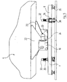
- Figur 7:
- eine vergrößerte Detailansicht im Bereich des mit dem Buchstaben A gekennzeichneten Kreises von Figur 2;
- Figur 8:
- eine vergrößerte Detailansicht im Bereich des mit dem Buchstaben B gekennzeichneten Kreises von Figur 2.
Die Verdrehung der Drehwelle 21 ist von einer entsprechenden Verdrehung der Fahrzeugkarosserie 4 um die Achse der Drehwelle 21 begleitet.
Claims (5)
- Anlage zur Behandlung, insbesondere zum Lackieren, von Gegenständen (4), deren Geometrie die Richtung einer Symmetrieachse oder einer Symmetrieebene oder eine Längsrichtung aufweist, insbesondere von Fahrzeugkarosserien, mita) mindestens einem Bad (2, 3), in dem sich eine Behandlungsflüssigkeit, insbesondere ein Lack, befindet, in welche die Gegenstände (4) eingetaucht werden sollen;b) einer Fördereinrichtung (5, 13, 14), mit welcher die Gegenstände (4) in einer kontinuierlichen oder intermittierenden Translationsbewegung in Transportrichtung durch die Anlage geführt werden können;c) einer Vielzahl von Eintaucheinrichtungen (19 bis 24), die mit der Fördereinrichtung (5, 13, 14) verbunden sind, jeweils einen Gegenstand (4) tragen und in der Lage sind, diesen Gegenstand (4) durch eine Drehung um eine sich unter einem Winkel zur Transportrichtung erstreckende Drehachse (21) vollständig in das Bad (2, 3) einzutauchen, wobei die Drehachse (21) von dem Gegenstand (4) beabstandet ist,
dadurch gekennzeichnet, daßd) die Eintaucheinrichtungen (19 bis 24) so ausgebildet sind, daß in derjenigen Drehposition, in der die Richtung der Symmetrieachse oder der Symmetrieebene oder die Längsrichtung des Gegenstandes (4) horizontal verläuft, die Transportrichtung unter einem schrägen Winkel zur Richtung der Symmetrieachse oder der Symmetrieebene oder zur Längsrichtung des Gegenstandes (4) verläuft. - Anlage nach Anspruch 1, dadurch gekennzeichnet, daß die Drehachse (21) in der Projektion auf eine horizontale Ebene unter einem schrägen Winkel zur Transportrichtung (6) der Transporteinrichtung (5, 13, 14) verläuft.
- Anlage nach Anspruch 1 oder 2, dadurch gekennzeichnet, daß die Drehachse (21) gegenüber der Horizontalen verkippt ist.
- Anlage nach einem der vorhergehenden Ansprüche, dadurch gekennzeichnet, daß der Gegenstand (4) in der Eintaucheinrichtung (19 bis 24) so montiert ist, daß seine Richtung der Symmetrieachse oder der Symmetrieebene oder seine Längsrichtung unter einem schrägen Winkel zur Drehachse (21) steht.
- Anlage nach einem der vorhergehenden Ansprüche, dadurch gekennzeichnet, daß der Winkel zwischen der Transportrichtung (6) und der Richtung der Symmetrieachse oder der Symmetrieebene oder der Längsrichtung der Gegenstände (4) einstellbar ist.
Applications Claiming Priority (2)
| Application Number | Priority Date | Filing Date | Title |
|---|---|---|---|
| DE10100167A DE10100167C2 (de) | 2001-01-04 | 2001-01-04 | Anlage zur Behandlung, insbesondere zum Lackieren von Gegenständen, deren Geometrie eine Vorzugsrichtung aufweist |
| DE10100167 | 2001-01-04 |
Publications (2)
| Publication Number | Publication Date |
|---|---|
| EP1221420A1 EP1221420A1 (de) | 2002-07-10 |
| EP1221420B1 true EP1221420B1 (de) | 2005-01-26 |
Family
ID=7669744
Family Applications (1)
| Application Number | Title | Priority Date | Filing Date |
|---|---|---|---|
| EP01127220A Expired - Lifetime EP1221420B1 (de) | 2001-01-04 | 2001-11-16 | Anlage zur Behandlung, insbesondere zum Lackieren, von Gegenständen, deren Geometrie eine Vorzugsrichtung aufweist |
Country Status (3)
| Country | Link |
|---|---|
| EP (1) | EP1221420B1 (de) |
| DE (2) | DE10100167C2 (de) |
| ES (1) | ES2234753T3 (de) |
Families Citing this family (5)
| Publication number | Priority date | Publication date | Assignee | Title |
|---|---|---|---|---|
| DE10210981B4 (de) * | 2002-03-13 | 2006-11-30 | Eisenmann Maschinenbau Gmbh & Co. Kg | Anlage zum Behandeln, insbesondere zum kataphoretischen Tauchlackieren, von Gegenständen, insbesondere von Fahrzeugkarosserien |
| DE10258132A1 (de) * | 2002-12-02 | 2004-06-17 | Dürr Automotion Gmbh | Vorrichtung und Verfahren zur Oberflächenbehandlung von Werkstücken |
| DE10308034B4 (de) * | 2003-02-24 | 2004-12-30 | EISENMANN Maschinenbau KG (Komplementär: Eisenmann-Stiftung) | Anlage zum Behandeln, insbesondere zum Lackieren von Gegenständen, insbesondere von Fahrzeugkarosserien |
| DE10318933A1 (de) * | 2003-04-26 | 2004-11-18 | Basf Coatings Ag | Elektrotauchlackierverfahren und Durchlaufanlage zu seiner Durchführung |
| DE102017107389A1 (de) * | 2017-04-06 | 2018-10-11 | Eisenmann Se | Tauchbehandlungsanlage und Verfahren zum Behandeln von Gegenständen, insbesondere von Fahrzeugkarosserien |
Family Cites Families (3)
| Publication number | Priority date | Publication date | Assignee | Title |
|---|---|---|---|---|
| BE480102A (de) * | 1944-01-06 | |||
| JPH0772012B2 (ja) * | 1988-10-28 | 1995-08-02 | 株式会社椿本チエイン | 物品の離隔搬送装置 |
| DE19641048C2 (de) * | 1996-10-04 | 2000-07-20 | Flaekt Ab | Verfahren zum Ein- und Ausbringen von Werkstücken, insbesondere Fahrzeugkarosserien, Vorrichtung und Anlage zur Oberflächenbehandlung von Werkstücken im Durchlauf |
-
2001
- 2001-01-04 DE DE10100167A patent/DE10100167C2/de not_active Expired - Lifetime
- 2001-11-16 EP EP01127220A patent/EP1221420B1/de not_active Expired - Lifetime
- 2001-11-16 ES ES01127220T patent/ES2234753T3/es not_active Expired - Lifetime
- 2001-11-16 DE DE50105190T patent/DE50105190D1/de not_active Expired - Lifetime
Also Published As
| Publication number | Publication date |
|---|---|
| DE10100167A1 (de) | 2002-09-05 |
| DE10100167C2 (de) | 2003-01-23 |
| DE50105190D1 (de) | 2005-03-03 |
| ES2234753T3 (es) | 2005-07-01 |
| EP1221420A1 (de) | 2002-07-10 |
Similar Documents
| Publication | Publication Date | Title |
|---|---|---|
| DE10063448C5 (de) | Anlage zur Behandlung, insbesondere zum Lackieren, von Gegenständen, insbesondere von Fahrzeugkarosserien | |
| EP1355742B1 (de) | Anlage zum behandeln, insbesondere zum lackieren, von gegenständen, insbesondere von fahrzeugkarosserien | |
| EP1347926B1 (de) | Anlage zum behandeln, insbesondere zum lackieren, von gegenständen, insbesondere von fahrzeugkarosserien | |
| EP1931580B1 (de) | Rollenbahnförderer | |
| EP2526038B1 (de) | Fördersystem zum transport von gegenständen und tauchbehandlungsanlage mit einem solchen | |
| EP2322414A2 (de) | Antriebseinheit, Antriebssystem und Förderanlage für Skids | |
| DE29724558U1 (de) | Vorrichtung zur Oberflächenbehandlung von Werkstücken | |
| DE3513381A1 (de) | Umlenk-verschiebe-modul fuer werkstuecke, werkstuecktraeger oder dergleichen | |
| DE10210942B4 (de) | Anlage zum Behandeln, insbesondere zum kataphoretischen Tauchlackieren, von Gegenständen, insbesondere von Fahrzeugkarosserien | |
| EP1221420B1 (de) | Anlage zur Behandlung, insbesondere zum Lackieren, von Gegenständen, deren Geometrie eine Vorzugsrichtung aufweist | |
| DE102007063061A1 (de) | Tauchbehandlungsanlage | |
| EP2969867B1 (de) | Vorrichtung und verfahren zum tauchlackieren grosser karosserien | |
| DE102017107389A1 (de) | Tauchbehandlungsanlage und Verfahren zum Behandeln von Gegenständen, insbesondere von Fahrzeugkarosserien | |
| EP1784288B1 (de) | Vorrichtung zum beschichten, insbesondere zum lackieren, von gegenständen, insbesondere von fahrzeugkarosserien | |
| DE102019113637A1 (de) | Freifahrender Transportwagen, Fördersystem und Behandlungsanlage | |
| EP1221346B1 (de) | Anlage zur Behandlung, insbesondere zum Lackieren, von Gegenständen, insbesondere von Fahrzeugkarosserien | |
| DE19950892B4 (de) | Vorrichtung zur Behandlung der Oberfläche von Gegenständen | |
| DE4324496C2 (de) | Vorrichtung zum Transportieren von Stückgütern in einer Durchlaufbehandlungsanlage, insbesondere für die Vorbehandlung und Elektrotauchlackierung von Fahrzeugkarosserien oder dergleichen | |
| DE10121055A1 (de) | Fördervorrichtung zum Fördern von Werkstücken durch einen Behandlungsbereich zur Oberflächenbehandlung der Werkstücke | |
| DE60100214T2 (de) | Schwenkstation für die Fördervorrichtung einer Behandlungsanlage | |
| EP3201108A1 (de) | Fördersystem für werkstücke | |
| DE2821192A1 (de) | Verfahren und anlage zum konservieren von teilen durch auftragen einer beschichtung im tauchverfahren | |
| DE10210943A1 (de) | Anlage zum Behandeln, insbesondere zum kataphoretischen Tauchlackieren, von Gegenständen, insbesondere von Fahrzeugkarosserien | |
| EP3078616A1 (de) | Tauchbehandlungsanlage zum tauchbehandeln von gegenständen |
Legal Events
| Date | Code | Title | Description |
|---|---|---|---|
| PUAI | Public reference made under article 153(3) epc to a published international application that has entered the european phase |
Free format text: ORIGINAL CODE: 0009012 |
|
| AK | Designated contracting states |
Kind code of ref document: A1 Designated state(s): AT BE CH CY DE DK ES FI FR GB GR IE IT LI LU MC NL PT SE TR |
|
| AX | Request for extension of the european patent |
Free format text: AL;LT;LV;MK;RO;SI |
|
| 17P | Request for examination filed |
Effective date: 20020805 |
|
| AKX | Designation fees paid |
Designated state(s): DE ES FR GB IT SE |
|
| 17Q | First examination report despatched |
Effective date: 20030311 |
|
| GRAP | Despatch of communication of intention to grant a patent |
Free format text: ORIGINAL CODE: EPIDOSNIGR1 |
|
| RTI1 | Title (correction) |
Free format text: TREATMENT DEVICE, ESPECIALLY FOR PAINTING OBJECTS HAVING A GEOMETRY WITH A PREFERRED ORIENTATION |
|
| GRAS | Grant fee paid |
Free format text: ORIGINAL CODE: EPIDOSNIGR3 |
|
| GRAA | (expected) grant |
Free format text: ORIGINAL CODE: 0009210 |
|
| RAP1 | Party data changed (applicant data changed or rights of an application transferred) |
Owner name: EISENMANN MASCHINENBAU GMBH & CO. KG |
|
| AK | Designated contracting states |
Kind code of ref document: B1 Designated state(s): DE ES FR GB IT SE |
|
| REG | Reference to a national code |
Ref country code: GB Ref legal event code: FG4D Free format text: NOT ENGLISH |
|
| GBT | Gb: translation of ep patent filed (gb section 77(6)(a)/1977) |
Effective date: 20050126 |
|
| REG | Reference to a national code |
Ref country code: IE Ref legal event code: FG4D Free format text: GERMAN |
|
| REF | Corresponds to: |
Ref document number: 50105190 Country of ref document: DE Date of ref document: 20050303 Kind code of ref document: P |
|
| REG | Reference to a national code |
Ref country code: SE Ref legal event code: TRGR |
|
| REG | Reference to a national code |
Ref country code: ES Ref legal event code: FG2A Ref document number: 2234753 Country of ref document: ES Kind code of ref document: T3 |
|
| PLBI | Opposition filed |
Free format text: ORIGINAL CODE: 0009260 |
|
| PLAX | Notice of opposition and request to file observation + time limit sent |
Free format text: ORIGINAL CODE: EPIDOSNOBS2 |
|
| 26 | Opposition filed |
Opponent name: DUERR SYSTEMS GMBH Effective date: 20051025 |
|
| ET | Fr: translation filed | ||
| PLAF | Information modified related to communication of a notice of opposition and request to file observations + time limit |
Free format text: ORIGINAL CODE: EPIDOSCOBS2 |
|
| PLBB | Reply of patent proprietor to notice(s) of opposition received |
Free format text: ORIGINAL CODE: EPIDOSNOBS3 |
|
| PLBP | Opposition withdrawn |
Free format text: ORIGINAL CODE: 0009264 |
|
| PLBD | Termination of opposition procedure: decision despatched |
Free format text: ORIGINAL CODE: EPIDOSNOPC1 |
|
| PLBM | Termination of opposition procedure: date of legal effect published |
Free format text: ORIGINAL CODE: 0009276 |
|
| STAA | Information on the status of an ep patent application or granted ep patent |
Free format text: STATUS: OPPOSITION PROCEDURE CLOSED |
|
| 27C | Opposition proceedings terminated |
Effective date: 20070322 |
|
| REG | Reference to a national code |
Ref country code: DE Ref legal event code: R081 Ref document number: 50105190 Country of ref document: DE Owner name: EISENMANN AG, DE Free format text: FORMER OWNER: EISENMANN ANLAGENBAU GMBH & CO. KG, 71032 BOEBLINGEN, DE Effective date: 20110513 |
|
| REG | Reference to a national code |
Ref country code: FR Ref legal event code: TP Owner name: EISENMANN AG, DE Effective date: 20120903 Ref country code: FR Ref legal event code: CD Owner name: EISENMANN AG, DE Effective date: 20120903 |
|
| REG | Reference to a national code |
Ref country code: ES Ref legal event code: PC2A Owner name: EISENMANN ANLAGENBAU GMBH & CO.KG Effective date: 20130614 |
|
| REG | Reference to a national code |
Ref country code: GB Ref legal event code: 732E Free format text: REGISTERED BETWEEN 20130606 AND 20130612 |
|
| REG | Reference to a national code |
Ref country code: ES Ref legal event code: PC2A Owner name: EISENMANN AG Effective date: 20130710 |
|
| PGFP | Annual fee paid to national office [announced via postgrant information from national office to epo] |
Ref country code: GB Payment date: 20131125 Year of fee payment: 13 |
|
| PGFP | Annual fee paid to national office [announced via postgrant information from national office to epo] |
Ref country code: FR Payment date: 20131125 Year of fee payment: 13 Ref country code: ES Payment date: 20131121 Year of fee payment: 13 |
|
| PGFP | Annual fee paid to national office [announced via postgrant information from national office to epo] |
Ref country code: SE Payment date: 20141121 Year of fee payment: 14 |
|
| PGFP | Annual fee paid to national office [announced via postgrant information from national office to epo] |
Ref country code: IT Payment date: 20141129 Year of fee payment: 14 |
|
| PGFP | Annual fee paid to national office [announced via postgrant information from national office to epo] |
Ref country code: DE Payment date: 20150130 Year of fee payment: 14 |
|
| GBPC | Gb: european patent ceased through non-payment of renewal fee |
Effective date: 20141116 |
|
| REG | Reference to a national code |
Ref country code: FR Ref legal event code: ST Effective date: 20150731 |
|
| PG25 | Lapsed in a contracting state [announced via postgrant information from national office to epo] |
Ref country code: GB Free format text: LAPSE BECAUSE OF NON-PAYMENT OF DUE FEES Effective date: 20141116 |
|
| PG25 | Lapsed in a contracting state [announced via postgrant information from national office to epo] |
Ref country code: FR Free format text: LAPSE BECAUSE OF NON-PAYMENT OF DUE FEES Effective date: 20141201 |
|
| REG | Reference to a national code |
Ref country code: ES Ref legal event code: FD2A Effective date: 20151229 |
|
| PG25 | Lapsed in a contracting state [announced via postgrant information from national office to epo] |
Ref country code: ES Free format text: LAPSE BECAUSE OF NON-PAYMENT OF DUE FEES Effective date: 20141117 |
|
| REG | Reference to a national code |
Ref country code: DE Ref legal event code: R119 Ref document number: 50105190 Country of ref document: DE |
|
| PG25 | Lapsed in a contracting state [announced via postgrant information from national office to epo] |
Ref country code: IT Free format text: LAPSE BECAUSE OF NON-PAYMENT OF DUE FEES Effective date: 20151116 |
|
| PG25 | Lapsed in a contracting state [announced via postgrant information from national office to epo] |
Ref country code: SE Free format text: LAPSE BECAUSE OF NON-PAYMENT OF DUE FEES Effective date: 20151117 |
|
| PG25 | Lapsed in a contracting state [announced via postgrant information from national office to epo] |
Ref country code: DE Free format text: LAPSE BECAUSE OF NON-PAYMENT OF DUE FEES Effective date: 20160601 |