EP1076478A2 - Method and device for monitoring a gas discharge lamp - Google Patents
Method and device for monitoring a gas discharge lamp Download PDFInfo
- Publication number
- EP1076478A2 EP1076478A2 EP00202736A EP00202736A EP1076478A2 EP 1076478 A2 EP1076478 A2 EP 1076478A2 EP 00202736 A EP00202736 A EP 00202736A EP 00202736 A EP00202736 A EP 00202736A EP 1076478 A2 EP1076478 A2 EP 1076478A2
- Authority
- EP
- European Patent Office
- Prior art keywords
- lamp
- measured value
- voltage
- value
- measured
- Prior art date
- Legal status (The legal status is an assumption and is not a legal conclusion. Google has not performed a legal analysis and makes no representation as to the accuracy of the status listed.)
- Withdrawn
Links
- 238000000034 method Methods 0.000 title claims abstract description 23
- 238000012544 monitoring process Methods 0.000 title claims abstract description 20
- 238000005259 measurement Methods 0.000 claims abstract description 8
- 238000004880 explosion Methods 0.000 abstract description 9
- 239000007789 gas Substances 0.000 description 23
- 239000010453 quartz Substances 0.000 description 5
- VYPSYNLAJGMNEJ-UHFFFAOYSA-N silicon dioxide Inorganic materials O=[Si]=O VYPSYNLAJGMNEJ-UHFFFAOYSA-N 0.000 description 5
- 238000001514 detection method Methods 0.000 description 4
- 238000010586 diagram Methods 0.000 description 4
- WFKWXMTUELFFGS-UHFFFAOYSA-N tungsten Chemical compound [W] WFKWXMTUELFFGS-UHFFFAOYSA-N 0.000 description 4
- 229910052721 tungsten Inorganic materials 0.000 description 4
- 239000010937 tungsten Substances 0.000 description 4
- 230000006870 function Effects 0.000 description 3
- 238000009434 installation Methods 0.000 description 3
- 230000003287 optical effect Effects 0.000 description 3
- 230000006378 damage Effects 0.000 description 2
- 238000011156 evaluation Methods 0.000 description 2
- 239000000463 material Substances 0.000 description 2
- 238000002844 melting Methods 0.000 description 2
- 230000008018 melting Effects 0.000 description 2
- 238000012806 monitoring device Methods 0.000 description 2
- 230000002028 premature Effects 0.000 description 2
- 230000036962 time dependent Effects 0.000 description 2
- UPLPHRJJTCUQAY-WIRWPRASSA-N 2,3-thioepoxy madol Chemical compound C([C@@H]1CC2)[C@@H]3S[C@@H]3C[C@]1(C)[C@@H]1[C@@H]2[C@@H]2CC[C@](C)(O)[C@@]2(C)CC1 UPLPHRJJTCUQAY-WIRWPRASSA-N 0.000 description 1
- 238000010521 absorption reaction Methods 0.000 description 1
- 230000009286 beneficial effect Effects 0.000 description 1
- 230000000903 blocking effect Effects 0.000 description 1
- 238000001816 cooling Methods 0.000 description 1
- 230000001934 delay Effects 0.000 description 1
- 230000001419 dependent effect Effects 0.000 description 1
- 238000013461 design Methods 0.000 description 1
- 238000011161 development Methods 0.000 description 1
- 230000000694 effects Effects 0.000 description 1
- 230000004907 flux Effects 0.000 description 1
- 239000011521 glass Substances 0.000 description 1
- 238000010438 heat treatment Methods 0.000 description 1
- 230000007774 longterm Effects 0.000 description 1
- 238000004519 manufacturing process Methods 0.000 description 1
- QSHDDOUJBYECFT-UHFFFAOYSA-N mercury Chemical compound [Hg] QSHDDOUJBYECFT-UHFFFAOYSA-N 0.000 description 1
- 229910052753 mercury Inorganic materials 0.000 description 1
- 238000001953 recrystallisation Methods 0.000 description 1
- 230000001105 regulatory effect Effects 0.000 description 1
- 230000002123 temporal effect Effects 0.000 description 1
Images


Classifications
-
- H—ELECTRICITY
- H05—ELECTRIC TECHNIQUES NOT OTHERWISE PROVIDED FOR
- H05B—ELECTRIC HEATING; ELECTRIC LIGHT SOURCES NOT OTHERWISE PROVIDED FOR; CIRCUIT ARRANGEMENTS FOR ELECTRIC LIGHT SOURCES, IN GENERAL
- H05B41/00—Circuit arrangements or apparatus for igniting or operating discharge lamps
- H05B41/14—Circuit arrangements
- H05B41/26—Circuit arrangements in which the lamp is fed by power derived from DC by means of a converter, e.g. by high-voltage DC
- H05B41/28—Circuit arrangements in which the lamp is fed by power derived from DC by means of a converter, e.g. by high-voltage DC using static converters
- H05B41/288—Circuit arrangements in which the lamp is fed by power derived from DC by means of a converter, e.g. by high-voltage DC using static converters with semiconductor devices and specially adapted for lamps without preheating electrodes, e.g. for high-intensity discharge lamps, high-pressure mercury or sodium lamps or low-pressure sodium lamps
- H05B41/292—Arrangements for protecting lamps or circuits against abnormal operating conditions
- H05B41/2921—Arrangements for protecting lamps or circuits against abnormal operating conditions for protecting the circuit against abnormal operating conditions
- H05B41/2925—Arrangements for protecting lamps or circuits against abnormal operating conditions for protecting the circuit against abnormal operating conditions against abnormal lamp operating conditions
-
- H—ELECTRICITY
- H05—ELECTRIC TECHNIQUES NOT OTHERWISE PROVIDED FOR
- H05B—ELECTRIC HEATING; ELECTRIC LIGHT SOURCES NOT OTHERWISE PROVIDED FOR; CIRCUIT ARRANGEMENTS FOR ELECTRIC LIGHT SOURCES, IN GENERAL
- H05B47/00—Circuit arrangements for operating light sources in general, i.e. where the type of light source is not relevant
- H05B47/20—Responsive to malfunctions or to light source life; for protection
-
- Y—GENERAL TAGGING OF NEW TECHNOLOGICAL DEVELOPMENTS; GENERAL TAGGING OF CROSS-SECTIONAL TECHNOLOGIES SPANNING OVER SEVERAL SECTIONS OF THE IPC; TECHNICAL SUBJECTS COVERED BY FORMER USPC CROSS-REFERENCE ART COLLECTIONS [XRACs] AND DIGESTS
- Y02—TECHNOLOGIES OR APPLICATIONS FOR MITIGATION OR ADAPTATION AGAINST CLIMATE CHANGE
- Y02B—CLIMATE CHANGE MITIGATION TECHNOLOGIES RELATED TO BUILDINGS, e.g. HOUSING, HOUSE APPLIANCES OR RELATED END-USER APPLICATIONS
- Y02B20/00—Energy efficient lighting technologies, e.g. halogen lamps or gas discharge lamps
Definitions
- the invention relates to a method for monitoring a gas discharge lamp to which an electrical measured value assigned to the lamp voltage is recorded, and also an Arrangement for monitoring a gas discharge lamp with a control circuit for Acquisition of an electrical measured value assigned to the lamp voltage.
- UHP lamps with internal lamp pressures of more than 200 bar
- Such UHP lamps essentially consist of approximately one round quartz pistons, in the side tungsten electrodes with a distance of 1.0 to 1.3 mm are melted down. A gas discharge builds up between these electrodes connected to an upward convection flow the piston top to temperatures near the melting point of quartz Piston wall can bring.
- the lamp increases over the life of the lamp Electrode distance by removing tungsten to the ends of the electrodes. Since the Lamps are regulated to a constant power, the voltage in the increases Lamp (burning voltage). In the event of an explosion, the housing parts surrounding the lamp become with broken glass and the materials inside the lamp (e.g. Mercury and other filling gases) contaminated. Therefore known lamp are preferred built into a closed reflector.
- ballast for use the operation of gas discharge lamps to monitor the life of the lamps.
- the ballast For recording lamp wear and for timely lamp replacement
- the ballast must be included a monitoring circuit provided, the long-term increase in the operating voltage the lamp is detected above a limit value and the ballast is switched off if necessary.
- the ballast has in a known manner that for operating a gas discharge lamp necessary functions (e.g. provision of operating performance and an ignition device).
- the ballast also contains a monitoring device (Control circuit) with a monitoring circuit for the burning voltage and a timer. The monitoring circuit detects the gas discharge Voltage or another voltage corresponding to this.
- the monitoring circuit indicates that the operating voltage has a preset limit a signal from their output. This signal is not used for blocking or Deactivate the source of the lamp, but is still on by means of the timer checked the time course. If the signal is present for a predetermined period of time, the food source is switched off.
- the object of the invention is therefore to better monitor gas discharge lamps to enable.
- better options for forecasting should be used the lifespan of the lamps and the danger of explosions.
- the object of the invention is achieved in that a clear one in the detection If the lamp voltage corresponding to the measured value drops, a warning signal is generated becomes.
- the electrical measured value can be proportional (e.g. one outside the lamp easily measurable voltage, which is preferably directly proportional to the lamp voltage) and also inversely proportional (e.g. the current supplied to the lamp) to the lamp voltage (Burning voltage).
- this is in contrast no increase or predominantly constant progression over known methods, but a time course of the lamp voltage with a negative slope is detected.
- the significant decrease can be based in particular on a characteristic negative slope the lamp voltage can be detected.
- the course of the lamp voltage can be the occurrence of a negative slope, for example over a certain period of time, a certain, adjustable absolute value or a Combination of both can be used.
- the measured value has a reference value it is compared that the deviation of the Measured value from the reference value corresponding difference value is formed, and that at Detection of a measured value assigned to an adjustable maximum difference value Warning signal is generated.
- the reference value is time-dependent, since it is preferably one corresponds to a certain point in time expected standard value for the respective lamp. Such standard values can be derived from measurements on similar lamps. Another option is a decision to generate the warning signal based on a detected minimum value of the lamp voltage. This minimum value can also time-dependent and linked to the respective reference value. The minimum value corresponds to a minimum of the lamp voltage at which the lamp for safety reasons must be switched off and replaced.
- the determination of a significant drop in the lamp voltage carries out the corresponding measured value and the warning signal when determining such Measurement value generated.
- EMG electronic ballasts
- This microprocessor is usually started in this way or can be easily expanded accordingly, the additional function the monitoring of the gas discharge lamp according to the invention.
- the microprocessor receives the measured value at regular time intervals that received during an adjustable burn-in phase of the gas discharge lamp Measured values not for determining a significant drop in lamp voltage the corresponding measured value, from 5 successive measured values each Slope of the measured value is determined, and if a negative slope of the Measured value generates the warning signal.
- These functions can be of a standard Microprocessor. To each by means of the supply cycle and one The microprocessor receives a measured value and counts the adjustable points in time it in a memory (e.g. a register). Similarly, there is also a time for that Burn-in phase of the lamp adjustable.
- the first few hours are through a burn-in phase the lamp in which there are voltage fluctuations that are not should be taken into account so that a first measured value is only saved afterwards (e.g. 2000h) becomes.
- a first measured value is only saved afterwards (e.g. 2000h) becomes.
- the microprocessor determines the slope of the measured value using standard mathematical processes. Depending on required accuracy and performance of the microprocessor used can the number of measured values and the time interval can of course be adjusted. At Determining a negative slope, an output of the microprocessor becomes active and so that the warning signal is generated.
- control circuit upon detection of a significant drop in lamp voltage corresponding measured value is provided for generating a warning signal.
- the Control circuit can, for example, by a suitably set microprocessor, hard-wired logic or in analog circuitry.
- Beneficial Embodiments of the arrangement according to the invention are in the further claims specified.
- the method according to the invention and the arrangement for monitoring a gas discharge lamp enable a largely reliable prediction of explosions and can cause the lamp to switch off in good time. It is not important whether the thermal load from internal processes in the lamp (e.g. recrystallization due to blackening) or combined with external loads (e.g. failure of the Device cooling).
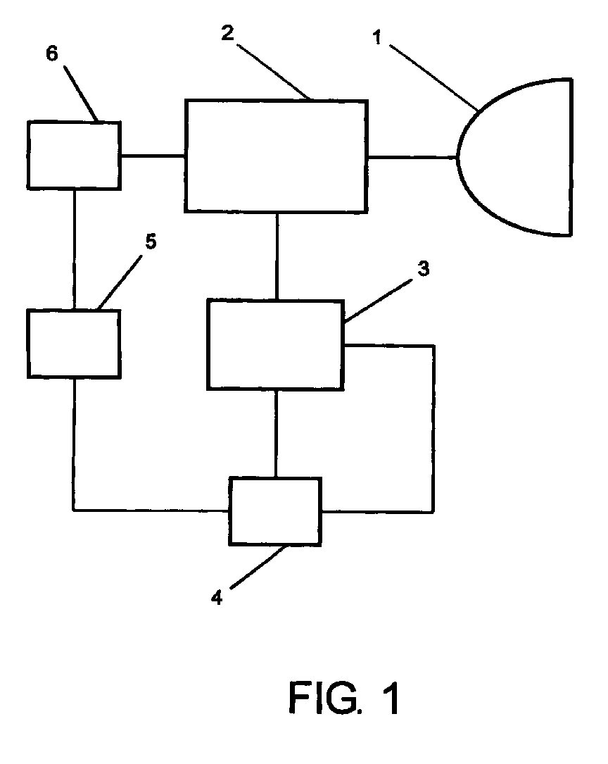
- FIG. 1 shows a block diagram of an arrangement according to the invention for monitoring a UHP gas discharge lamp 1 is shown.
- An electronic pre-hooking device (EVG) 2 supplies in a known manner all of the supply voltages required to operate the UHP lamp 1.
- a voltage measuring device 3 measures the one supplied to the UHP lamp 1 Tension.
- a microprocessor 4 receives the measured voltage values to be adjustable Times that are displayed to the voltage measuring device 3 by means of a control signal become.
- the voltage measuring device 3 and the microprocessor 4 in the electronic ballast 2 be integrated or built in.
- a display device 5 At an output of the microprocessor 4 is a display device 5 connected, which is indicated by an optical display when a Lamp change should be made.
- the microprocessor 4 gives a display signal out.
- the display can, for example, by a simple, color-coded LED or by an LCD display.
- the display device 5 not necessarily be arranged in the vicinity of the UHP lamp 1 in addition or alternatively, an acoustic display can also be provided.
- the design can be adjusted depending on the application and the requirements.
- a shutdown device 6 is also connected to the output of the microprocessor 4. When the microprocessor 4 outputs a shutdown signal, the shutdown device 6 conducts this Switch off the ECG 2 and thus the lamp 1 on.
- a Output of the microprocessor 4 are used, on which two different signals are output by the display device 5 or the shutdown device 6 are processed. Another way to implement it is to use it of 2 independent outputs of the microprocessor 4, on which a simple active signal issued and the display device 5 and the shutdown device 6 on separate Lines is supplied.
- the arc length of the gas discharge increases in the UHP lamp 1 during the service life and thus the thermal Load on the top of the piston due to the gas discharge combined with the upward direction Convection flow.
- additional blackening absorption means additional heating
- thermally stressed installation conditions begins to soften the top of the piston.
- the quartz melting point As the temperature on the top of the piston reaches into the If the quartz melting point is increased, the quartz flows until the tensile strength of the softening quartz corresponds to the falling internal pressure.
- a voltage drop of the UHP lamp 1 which is no longer the standard values of the corresponds to normal lamp operation and thus for detection of the inflation of the UHP lamp 1 can be used.
- the UHP lamp 1 is then expediently switched off, to rule out an explosion.
- the time when this effect occurs is of various parameters of lamp and electrode production, power and the mode of operation is just as dependent on the installation situation of the UHP lamp 1 in an optical system. Every single UHP lamp 1 must therefore be monitored.
- the voltage curve of the UHP lamp 1 over time is characterized by a constant increase in tension, apart from the first approximately 2000 h. Due to the fact that, depending on the mode of operation, the removal is constant but constant of tungsten from the molten electrode tips. This leads to an enlargement the electrode spacing and thus to higher voltage values.
- the slope the voltage curve over time depends on the operating mode of the lamp. So show, for example, measurements on two differently operated lamps A and B to an almost constant voltage curve for about 6000 h, then the voltage drops significantly from. This is a sign of reduced lamp pressure caused by inflation of the Lamp bulb is caused. After 7000 h both lamps are still undamaged, however, showed deformations of 0.9 mm and 1.0 mm.
- FIG. 2 An exemplary embodiment of a method for monitoring according to the invention is shown in FIG. 2 by means of a flow diagram.
- the voltage measuring device 3 supplies a measured value M, which is received by the microprocessor 4.
- An adjustable time loop can also be provided in the microprocessor 4, which delays the evaluation of the measured values M by an adjustable burn-in phase T 0 .
- the measured value M is compared with a selectable reference value R, which is derived from a standard value for the lamp 1 determined from measurements and is supplied to the microprocessor 4.
- the measured value M and the reference value R indicate a voltage which is proportional to the operating voltage in the UHP lamp 1 and which can easily be measured in the ballast 2.
- a timer is used only after about 2000 h at regular intervals of e.g. B. 100 h measured the voltage. If a measured value M is smaller than the reference value R, there is a significant drop in the lamp voltage (operating voltage of the UHP lamp 1). As soon as the comparison yields a smaller measured value M than the reference value R, a delay time T 'is reset to the value 0. The delay time T 'is compared with an adjustable waiting time T 1 '. Until the waiting time T 1 'is reached, it is checked whether the current measured value M is still smaller than the reference value R and the delay time T' is incremented.
- FIG. 3 shows a flow diagram of a further embodiment of the monitoring method according to the invention.
- a loop for delaying the evaluation of the measured values M by an adjustable burn-in phase T 0 is not shown, but can be provided in a similar manner in the microprocessor 4.
- the warning signal is generated.
- the last 5 measured values M 1 ,... M 5 scatter of the measured values M i or brief voltage changes that can occur due to material transport at the electrodes are suppressed.
- the calculation of the slope ⁇ of the voltage over time using first-order regression is particularly advantageous, since with this method short-term voltage changes and scattering do not lead to premature switching off. Only when the slope ⁇ calculated in this way becomes negative is there an indicator for the inflation of the lamp bulb. This can be displayed both as a warning for the replacement of the lamp 1 or for switching off in order to avoid explosion of the lamp 1.
Landscapes
- Circuit Arrangements For Discharge Lamps (AREA)
- Circuit Arrangement For Electric Light Sources In General (AREA)
- Manufacture Of Electron Tubes, Discharge Lamp Vessels, Lead-In Wires, And The Like (AREA)
Abstract
Die Erfindung betrifft ein Verfahren zur Überwachung einer Gasentladungslampe, bei
dem ein der Lampenspannung zugeordneter elektrischer Messwert erfasst wird, sowie eine
Anordnung zur Überwachung einer Gasentladungslampe mit einer Kontrollschaltung zur
Erfassung eines der Lampenspannung zugeordneten elektrischen Messwertes. Um bessere
Möglichkeiten zur Vorhersage der Lebensdauer der Lampen und der Gefahr durch Explosionen
zu realisieren, wird vorgeschlagen, bei der Erfassung eines einem deutlichen Absinken
der Lampenspannung entsprechenden Messwertes ein Warnsignal zu erzeugen. Der
elektrische Messwert kann sowohl proportional (z.B. eine außerhalb der Lampe einfach
messbare Spannung, die vorzugsweise direkt proportional zur Lampenspannung ist) als
auch umgekehrt proportional (z.B. der der Lampe zugeführte Strom) zur Lampenspannung
(Brennspannung) sein.
Description
Die Erfindung betrifft ein Verfahren zur Überwachung einer Gasentladungslampe, bei dem ein der Lampenspannung zugeordneter elektrischer Messwert erfasst wird, sowie eine Anordnung zur Überwachung einer Gasentladungslampe mit einer Kontrollschaltung zur Erfassung eines der Lampenspannung zugeordneten elektrischen Messwertes.The invention relates to a method for monitoring a gas discharge lamp to which an electrical measured value assigned to the lamp voltage is recorded, and also an Arrangement for monitoring a gas discharge lamp with a control circuit for Acquisition of an electrical measured value assigned to the lamp voltage.
Das Ende der Lebensdauer von Hochdruckgasentladungslampen mit Lampeninnendrücken von mehr als 200 bar (z. B. UHP) ist häufig gekennzeichnet durch eine Explosion des Lampenkolbens. Solche UHP-Lampen bestehen im wesentlichen aus einem annähernd runden Quarzkolben, in den seitlich Wolframelektroden mit einem Abstand von 1.0 bis 1.3 mm eingeschmolzen sind.. Zwischen diesen Elektroden baut sich eine Gasentladung auf, die verbunden mit einer aufwärtsgerichteten Konvektionsströmung die Kolbenoberseite auf Temperaturen in die Nähe des Schmelzpunktes der aus Quarz bestehenden Kolbenwand bringen kann. Während der Lebensdauer der Lampen vergrößert sich der Elektrodenabstand durch Abtransport von Wolfram zu den Elekttodenenden. Da die Lampen auf eine konstante Leistung geregelt werden, erhöht sich die Spannung in der Lampe (Brennspannung). Bei einer Explosion werden die die Lampe umgebenden Gehäuseteile mit Glassplittern und den im Inneren der Lampe befindlichen Materialien (z.B. Quecksilber und andere Füllgase) kontaminiert. Deshalb werden bekannte Lampe vorrugsweise in einen geschlossenen Reflektor eingebaut.The end of the service life of high pressure gas discharge lamps with internal lamp pressures of more than 200 bar (e.g. UHP) is often characterized by an explosion of the Lamp bulb. Such UHP lamps essentially consist of approximately one round quartz pistons, in the side tungsten electrodes with a distance of 1.0 to 1.3 mm are melted down. A gas discharge builds up between these electrodes connected to an upward convection flow the piston top to temperatures near the melting point of quartz Piston wall can bring. The lamp increases over the life of the lamp Electrode distance by removing tungsten to the ends of the electrodes. Since the Lamps are regulated to a constant power, the voltage in the increases Lamp (burning voltage). In the event of an explosion, the housing parts surrounding the lamp become with broken glass and the materials inside the lamp (e.g. Mercury and other filling gases) contaminated. Therefore known lamp are preferred built into a closed reflector.
Bei kleinen Reflektorsystemen mit Lampen hoher Leistung ist der Einbau innerhalb eines geschlossenen Reflektors aus thermischen Aspekten äußerst schwierig. Die Verwendung einer durchbohrten Frontscheibe mit dem freien Lampenende außerhalb des Reflektors zur Verminderung der thermischen Probleme hat den Nachteil, dass mögliche Explosionsrückstände aus dem Reflektor austreten und innerhalb des Gehäuses (z.B. Projektor) Schaden anrichten können. In the case of small reflector systems with high-output lamps, installation is within one closed reflector extremely difficult from a thermal point of view. The usage a pierced windscreen with the free lamp end outside of the reflector Reducing the thermal problems has the disadvantage that possible explosion residues emerge from the reflector and damage inside the housing (e.g. projector) can wreak havoc.
Aus der deutschen Offenlegungsschrift DE 197 15 254 ist bekannt, ein Vorschaltgerät für den Betrieb von Gasentladungslampen zur Lebensdauerüberwachung der Lampen zu verwenden. Zur Erfassung des Lampenverschleißes und um einen rechtzeitigen Lampenwechsel bei Hochdruckgasentladungslampen zu ermöglichen, ist das Vorschaltgerät mit einer Überwachungsschaltung versehen, die ein längerfristiges Erhöhen der Brennspannung der Lampe über einen Grenzwert hinaus erfasst und ggf. das Vorschaltgerät abschaltet. Das Vorschaltgerät besitzt in bekannter Weise die zum Betrieb einer Gasentladungslampe notwendigen Funktionen (beispielsweise Bereitstellung der Betriebsleistung und eine Zündeinrichtung). Zusätzlich enthält das Vorschaltgerät noch eine Überwachungseinrichtung (Kontrollschaltung) mit einer Überwachungsschaltung für die Brennspannung und einer Zeitschaltung. Die Überwachungsschaltung erfasst die an der Gasentladung anliegende Spannung oder eine andere, dieser entsprechende Spannung. Überschreitet die Brennspannung einen voreinstellbaren Grenzwert, gibt die Überwachungsschaltung an ihrem Ausgang ein Signal ab. Dieses Signal dient nicht unmittelbar zum Sperren oder Inaktivieren der Speisequelle der Lampe, sondern wird mittels der Zeitschaltung noch auf den zeitlichen Verlauf überprüft. Wenn das Signal eine vorbestimmte Zeitspanne anliegt, wird die Speisequelle abgeschaltet.From the German patent application DE 197 15 254 it is known a ballast for use the operation of gas discharge lamps to monitor the life of the lamps. For recording lamp wear and for timely lamp replacement In the case of high-pressure gas discharge lamps, the ballast must be included a monitoring circuit provided, the long-term increase in the operating voltage the lamp is detected above a limit value and the ballast is switched off if necessary. The ballast has in a known manner that for operating a gas discharge lamp necessary functions (e.g. provision of operating performance and an ignition device). The ballast also contains a monitoring device (Control circuit) with a monitoring circuit for the burning voltage and a timer. The monitoring circuit detects the gas discharge Voltage or another voltage corresponding to this. Exceeds the The monitoring circuit indicates that the operating voltage has a preset limit a signal from their output. This signal is not used for blocking or Deactivate the source of the lamp, but is still on by means of the timer checked the time course. If the signal is present for a predetermined period of time, the food source is switched off.
Verfahren und Anordnungen zur Überwachung von Gasentladungslampen nach dem Stand der Technik überwachen die Brennspannung der Lampen nur hinsichtlich eines Anstieges bis ein Grenzwert erreicht wird. Solche Verfahren sind hilfreich für die Lampen, deren Brennspannung aufgrund zurückgehender Elektroden über die Lebensdauer ansteigt. Das Überschreiten eines Grenzwertes kann als Abschaltsignal verwendet werden, um eine Zerstörung der Lampe zu verhindern. Oft erreichen Gasentladungslampen die durch eine Maximalspannung gekennzeichnete Maximallebensdauer nicht, weil die Lampe vorher durch andere Ursachen zerstört wird. So entstehen insbesondere bei nicht optimaler Fül-lung der Lampe vor dem Erreichen der Maximalspannung Abschwärzungen an der Innenseite des Entladungsgefäßes (Lampenkolben). Dies führt zu einer Volumenvergrößerung des Lampenkolbens (fortwährendes Aufblasen) und damit zu einer Druckabnahme. Da trotz weiterer Vergrößerung des Elektrodenabstandes die Brennspannung aufgrund der Druckabnahme nicht weiter steigt, kann die Gefahr der Explosion der Lampe von bekannten Überwachungseinrichtungen nicht detektiert werden. Methods and arrangements for monitoring gas discharge lamps according to the State of the art monitor the burning voltage of the lamps only with regard to one Rise until a limit is reached. Such procedures are helpful for the lamps, whose burning voltage rises over the service life due to electrodes receding. Exceeding a limit value can be used as a switch-off signal to To prevent destruction of the lamp. Often gas discharge lamps reach through a Maximum life marked maximum life not because the lamp before is destroyed by other causes. This is particularly the case when the filling is not optimal blackening of the lamp on the inside before reaching the maximum voltage of the discharge vessel (lamp bulb). This leads to an increase in volume of the lamp bulb (constant inflation) and thus to a decrease in pressure. There despite a further increase in the electrode spacing, the operating voltage due to the Decrease in pressure does not increase further, the risk of explosion of the lamp can be known Monitoring devices are not detected.
Die Aufgabe der Erfindung ist es daher, eine bessere Überwachung von Gasentladungslampen zu ermöglichen. Dabei sollen insbesondere bessere Möglichkeiten zur Vorhersage der Lebensdauer der Lampen und der Gefahr durch Explosionen realisiert werden.The object of the invention is therefore to better monitor gas discharge lamps to enable. In particular, better options for forecasting should be used the lifespan of the lamps and the danger of explosions.
Die Aufgabe der Erfindung wird dadurch gelöst, dass bei der Erfassung eines einem deutlichen Absinken der Lampenspannung entsprechenden Messwertes ein Warnsignal erzeugt wird. Der elektrische Messwert kann sowohl proportional (z.B. eine außerhalb der Lampe einfach messbare Spannung, die vorzugsweise direkt proportional zur Lampenspannung ist) als auch umgekehrt proportional (z.B. der der Lampe zugeführte Strom) zur Lampenspannung (Brennspannung) sein. Mittels des vorgeschlagenen Verfahrens wird damit im Gegensatz zu bekannten Verfahren kein Ansteigen oder zeitlich vorwiegend konstanter Verlauf, sondern ein zeitlicher Verlauf der Lampenspannung mit negativer Steigung detektiert. Das deutliche Absinken kann insbesondere anhand einer kennzeichnenden negativen Steigung der Lampenspannung detektiert werden. Als zusätzliches Merkmal für den zeitlichen Verlauf der Lampenspannung kann beispielsweise das Auftreten einer negativen Steigung über einen bestimmten Zeitraum, ein bestimmter, einstellbarer absoluter Wert oder eine Kombination aus beiden herangezogen werden.The object of the invention is achieved in that a clear one in the detection If the lamp voltage corresponding to the measured value drops, a warning signal is generated becomes. The electrical measured value can be proportional (e.g. one outside the lamp easily measurable voltage, which is preferably directly proportional to the lamp voltage) and also inversely proportional (e.g. the current supplied to the lamp) to the lamp voltage (Burning voltage). By means of the proposed method, this is in contrast no increase or predominantly constant progression over known methods, but a time course of the lamp voltage with a negative slope is detected. The significant decrease can be based in particular on a characteristic negative slope the lamp voltage can be detected. As an additional feature for the temporal The course of the lamp voltage can be the occurrence of a negative slope, for example over a certain period of time, a certain, adjustable absolute value or a Combination of both can be used.
In einer Ausgestaltung der Erfindung ist vorgesehen, dass der Messwert mit einem Referenzwert verglichen wird, dass jeweils zu einem Messwert ein der Abweichung des Messwertes vom Referenzwert entsprechender Differenzwert gebildet wird, und dass bei Erfassen eines einem einstellbaren maximalen Differenzwert zugeordneten Messwertes ein Warnsignal erzeugt wird. Der Referenzwert ist zeitabhängig, da er vorzugsweise einem zu einem bestimmten Zeitpunkt für die jeweilige Lampe erwarteten Standardwert entspricht. Solche Standardwerte können aus Messungen an ähnlichen Lampen abgeleitet werden. Eine weitere Möglichkeit ist eine Entscheidung zur Erzeugung des Warnsignals anhand eines detektierten Minimalwertes der Lampenspannung. Dieser Minimalwert kann ebenfalls zeitabhängig und an den jeweiligen Referenzwert gekoppelt sein. Der Minimalwert entspricht einem Minimum der Lampenspannung, bei dem die Lampe aus Sicherheitsgründen abgeschaltet und ausgetauscht werden muss. In one embodiment of the invention, it is provided that the measured value has a reference value it is compared that the deviation of the Measured value from the reference value corresponding difference value is formed, and that at Detection of a measured value assigned to an adjustable maximum difference value Warning signal is generated. The reference value is time-dependent, since it is preferably one corresponds to a certain point in time expected standard value for the respective lamp. Such standard values can be derived from measurements on similar lamps. Another option is a decision to generate the warning signal based on a detected minimum value of the lamp voltage. This minimum value can also time-dependent and linked to the respective reference value. The minimum value corresponds to a minimum of the lamp voltage at which the lamp for safety reasons must be switched off and replaced.
In einer bevorzugten Weiterbildung der Erfindung ist vorgesehen, dass ein in einem zum Betrieb der Gasentladungslampe geeigneten Vorschaltgerät enthaltener Mikroprozessor den Messwert empfängt, die Ermittlung des einem deutlichen Absinken der Lampenspannung entsprechenden Messwertes durchführt und das Warnsignal bei Ermittlung eines solchen Messwertes erzeugt. In bekannten zum Betrieb von Gasentladungslampen verwendeten elektronischen Vorschaltgeräten (EVG) ist meist ein Mikroprozessor enthalten, der Zündspannung, Frequenz, Pulshöhe und Leistung steuert und die Lampe bei niedriger Betriebsspannung auf halbe Leistung zurückschaltet. Dieser Mikroprozessor ist meist derart ausgestartet oder kann auf einfache Weise entsprechend erweitert werden, die zusätzliche Funktion der Überwachung der Gasentladungslampe gemäß der Erfindung durchzuführen.In a preferred development of the invention it is provided that one in a Operation of the gas discharge lamp suitable ballast microprocessor included Measured value received, the determination of a significant drop in the lamp voltage carries out the corresponding measured value and the warning signal when determining such Measurement value generated. In known for the operation of gas discharge lamps used electronic ballasts (EVG) usually contains a microprocessor, the ignition voltage, Frequency, pulse height and power controls and the lamp at low operating voltage switches back to half power. This microprocessor is usually started in this way or can be easily expanded accordingly, the additional function the monitoring of the gas discharge lamp according to the invention.
Bei einer vorteilhaften Ausgestaltung des erfindungsgemäßen Verfahrens ist vorgesehen, dass der Mikroprozessor den Messwert in regelmäßigen zeitlichen Abständen empfangt, die während einer einstellbaren Einbrennphase der Gasentladungslampe empfangenen Messwerte nicht zur Ermittlung des einem deutlichen Absinken der Lampenspannung entsprechenden Messwertes heranzieht, aus jeweils 5 aufeinanderfolgenden Messwerten die Steigung des Messwertes ermittelt, und bei Ermittlung einer negativen Steigung des Messwertes das Warnsignal erzeugt. Diese Funktionen können von einen üblichen Mikroprozessor ausgeführt werden. Jeweils zu mittels des Versorgungstaktes und eines Zählers einstellbaren Zeitpunkten empfangt der Mikroprozessor einen Messwert und legt ihn in einem Speicher (z.B. ein Register) ab. In ähnlicher Weise ist auch eine Zeit für die Einbrennphase der Lampe einstellbar. Die ersten Stunden sind durch eine Einbrennphase der Lampe gekennzeichnet, in der es zu Spannungsschwankungen kommt, die nicht berücksichtigt werden sollen, so dass erst danach (z.B. 2000h) ein erster Messwert gespeichert wird. Wenn fünf Messwerte im Speicher enthalten sind, ermittelt der Mikroprozessor mittels üblicher mathematischer Prozesse die Steigung des Messwertes. Je nach erforderlicher Genauigkeit und Leistungsvermögen des verwendeten Mikroprozessors kann die Anzahl der Messwerte und der zeitliche Abstand natürlich angepasst werden. Bei Ermittlung einer negativen Steigung wird ein Ausgang des Mikroprozessors aktiv und damit das Warnsignal erzeugt. In an advantageous embodiment of the method according to the invention, that the microprocessor receives the measured value at regular time intervals that received during an adjustable burn-in phase of the gas discharge lamp Measured values not for determining a significant drop in lamp voltage the corresponding measured value, from 5 successive measured values each Slope of the measured value is determined, and if a negative slope of the Measured value generates the warning signal. These functions can be of a standard Microprocessor. To each by means of the supply cycle and one The microprocessor receives a measured value and counts the adjustable points in time it in a memory (e.g. a register). Similarly, there is also a time for that Burn-in phase of the lamp adjustable. The first few hours are through a burn-in phase the lamp in which there are voltage fluctuations that are not should be taken into account so that a first measured value is only saved afterwards (e.g. 2000h) becomes. If there are five readings in the memory, the microprocessor determines the slope of the measured value using standard mathematical processes. Depending on required accuracy and performance of the microprocessor used can the number of measured values and the time interval can of course be adjusted. At Determining a negative slope, an output of the microprocessor becomes active and so that the warning signal is generated.
Des weiteren wird die Aufgabe der Erfindung auch noch durch eine Anordnung gelöst, bei der die Kontrollschaltung bei der Erfassung eines einem deutlichen Absinken der Lampenspannung entsprechenden Messwertes zur Erzeugung eines Warnsignals vorgesehen ist. Die Kontrollschaltung kann beispielsweise durch einen geeignet eingestellten Mikroprozessor, eine festverdrahtete Logik oder in analoger Schaltungstechnik realisiert sein. Vorteilhafte Ausgestaltungen der erfindungsgemäßen Anordnung sind in den weiteren Ansprüchen angegeben.Furthermore, the object of the invention is also achieved by an arrangement in which the control circuit upon detection of a significant drop in lamp voltage corresponding measured value is provided for generating a warning signal. The Control circuit can, for example, by a suitably set microprocessor, hard-wired logic or in analog circuitry. Beneficial Embodiments of the arrangement according to the invention are in the further claims specified.
Das erfindungsgemäße Verfahren und die Anordnung zur Überwachung einer Gasentladungslampe ermöglichen eine weitgehend zuverlässige Vorhersage von Explosionen und können dadurch ein rechtzeitiges Abschalten der Lampe bewirken. Dabei ist es unwichtig, ob die thermische Belastung durch innere Vorgänge in der Lampe (z.B. Rekristallisation durch Ahschwärzungen) oder auch kombiniert mit äußeren Belastungen (z.B. Ausfall der Gerätekühlung) hervorgerufen wird.The method according to the invention and the arrangement for monitoring a gas discharge lamp enable a largely reliable prediction of explosions and can cause the lamp to switch off in good time. It is not important whether the thermal load from internal processes in the lamp (e.g. recrystallization due to blackening) or combined with external loads (e.g. failure of the Device cooling).
Im folgenden soll ein Ausführungsbeispiel der Erfindung anhand von Zeichnungen näher erläutert werden. Dabei zeigen
- Figur 1:
- ein Blockdiagramm einer Anordnung zur Überwachung einer Gasentladungslampe,
- Figur 2:
- ein Flussdiagramm mit einem Ablauf des erfindungsgemäßen Verfahrens zur Überwachung einer Gasentladungslampe und
- Figur 3:
- ein Flussdiagramm mit einem weiteren Ablauf des erfindungsgemäßen Verfahrens zur Überwachung einer Gasentladungslampe.
- Figure 1:
- 1 shows a block diagram of an arrangement for monitoring a gas discharge lamp,
- Figure 2:
- a flowchart with a sequence of the inventive method for monitoring a gas discharge lamp and
- Figure 3:
- a flowchart with a further sequence of the method according to the invention for monitoring a gas discharge lamp.
In der Figur 1 ist ein Blockdiagramm einer erfindungsgemäßen Anordnung zur Überwachung
einer UHP-Gasentladungslampe 1 dargestellt. Ein elektronisches Vorschakgerät
(EVG) 2 liefert in bekannter Weise alle zum Betrieb der UHP-Lampe 1 notwendigen Versorgungsspannungen.
Ein Spannungsmessgerät 3 misst die der UHP-Lampe 1 zugeführte
Spannung. Ein Mikroprozessor 4 empfängt die gemessenen Spannungswerte zu einstellbaren
Zeitpunkten, die mittels eines Steuersignals dem Spannungsmessgerät 3 angezeigt
werden. Selbstverständlich kann trotz der zur Vereinfachung gewählten Darstellung in
getrennten Blöcken das Spannungsmessgerät 3 und der Mikroprozessor 4 im EVG 2
integriert bzw. eingebaut sein. An einem Ausgang des Mikroprozessors 4 ist eine Anzeigevorrichtung
5 angeschlossen, die durch eine optische Anzeige signalisiert, wann ein
Lampenwechsel vorgenommen werden soll. Dazu gibt der Mikroprozessor 4 ein Anzeigesignal
aus. Die Anzeige kann beispielsweise durch eine einfache, farblich gekennzeichnete
LED oder durch eine LCD-Anzeige realisiert werden. Insbesondere muss die Anzeigevorrichtung
5 nicht zwangsweise in der Nähe der UHP-Lampe 1 angeordnet sein Zusätzlich
oder ersatzweise kann auch eine akustische Anzeige vorgesehen werden. Die Ausgestaltung
kann in Abhängigkeit der Anwendung und der Erfordernisse angepasst werden. Eine Abschaltvorrichtung
6 ist ebenfalls mit dem Ausgang des Mikroprozessors 4 verbunden.
Wenn der Mikroprozessor 4 ein Abschaltsignal ausgibt, leitet die Abschaltvorrichtung 6 das
Abschalten des EVG 2 und damit der Lampe 1 ein. Je nach Anwendung kann dabei ein
Ausgang des Mikroprozessors 4 verwendet werden, auf dem zwei unterschiedliche Signale
ausgegeben werden, die von der Anzeigevorrichtung 5 oder der Abschaltvorrichtung 6
verarbeitet werden. Eine andere Möglichkeit zur Realisierung besteht in der Verwendung
von 2 unabhängigen Ausgängen des Mikroprozessors 4, auf denen ein einfaches Aktivsignal
ausgegeben und der Anzeigevorrichtung 5 und der Abschaltvorrichtung 6 auf separaten
Leitungen zugeführt wird.1 shows a block diagram of an arrangement according to the invention for monitoring
a UHP
Durch Abtransport von Wolfram zu den Elektrodenenden nimmt die Bogenlänge der Gasentladung
in der UHP-Lampe 1 während der Lebensdauer zu und damit die thermische
Belastung der Kolbenoberseite durch die Gasentladung verbunden mit der aufwärtsgerichteten
Konvektionsströmung. Durch zusätzliche Abschwärzung (Absorption bedeutet
zusätzliche Erwärmung) oder/und thermisch belastete Einbaubedingungen, beginnt sich
die Kolbenoberseite zu erweichen. Da die Temperatur an der Kolbenoberseite bis in die
Nähe des Schmelzpunktes des Quarzes erhöht ist, fließt das Quarz soweit, bis die Zugfestigkeit
des erweichenden Quarzes dem sinkenden Innendruck entspricht. Damit verbunden
ist ein Spannungsabfall der UHP-Lampe 1, der nicht mehr Standardwerten des
normalen Lampenbetriebes entspricht und somit zur Detektion des Aufblasens der UHP-Lampe
1 benutzt werden kann. Zweckmäßigerweise wird die UHP-Lampe 1 dann ausgeschaltet,
um eine Explosion auszuschließen. Der Zeitpunkt, wann dieser Effekt auftritt, ist
von verschiedenen Parametern der Lampen- und Elektrodenproduktion, der Leistung und
der Betriebsweise ebenso abhängig, wie von der Einbausituation der UHP-Lampe 1 in
einem optischen System. Deshalb muss jede einzelne UHP-Lampe 1 überwacht werden.By removing tungsten to the electrode ends, the arc length of the gas discharge increases
in the
Der Spannungsverlauf der UHP-Lampe 1 über der Zeit ist gekennzeichnet durch eine
stetige Zunahme der Spannung, wenn man von den ersten etwa 2000 h absieht. Verantwortlich
dafür ist der, je nach Betriebsweise unterschiedlich hohe, jedoch stetige Abtransport
von Wolfram von den geschmolzenen Elektrodenspitzen. Dies führt zu einer Vergrößerung
des Elektrodenabstandes und damit zu höheren Spannungswerten. Die Steigung
der Spannungsverlaufes über der Zeit ist abhängig von der Betriebsweise der Lampe. So
zeigen zum Beispiel Messungen an zwei unterschiedlich betriebenen Lampen A und B bis
etwa 6000 h einen nahezu konstanten Spannungsverlauf, danach sinkt die Spannung deutlich
ab. Dies ist ein Zeichen für einen reduzierten Lampendruck, der durch Aufblasen des
Lampenkolbens hervorgerufen wird. Nach 7000 h sind beide Lampen zwar noch unbeschädigt,
zeigten jedoch Verformungen von 0.9 mm bzw. 1.0 mm. Dagegen zeigen zwei
Lampen C und D bis 4000 h bzw. 5000 h einen stetigen Spannungsanstieg, danach eine
deutliche Abnahme der Spannung. Während die Lampe C nach etwa 6600 h explodiert,
zeigt die Lampe D nach 7000 h eine Verformung von 0.8 mm. Mit diesem Spannungsabfall
sinken auch die für ein optisches System brauchbaren Lichtströme soweit, dass ein Auswechseln
der UHP-Lampe 1 aus diesem Grund erforderlich ist, obwohl sie noch funktioniert.
Der oben beschriebene Spannungsabfall wird erfindungsgemäß detektiert im Vorschaltgerät
2, welches einen Mikroprozessor 4 beinhaltet, der Zündspannung, Frequenz,
Pulshöhe und Leistung steuert und die UHP-Lampe 1 bei niedriger Betriebsspannung auf
halbe Leistung zurückschaltet.The voltage curve of the
Ein Ausführungsbeispiel eines Verfahrens zur Überwachung gemäß der Erfindung ist in
der Figur 2 mittels eines Flussdiagramms dargestellt. Das Spannungsmessgerät 3 liefert
einen Messwert M, der vom Mikroprozessor 4 empfangen wird. Im Mikroprozessor 4
kann noch eine einstellbare Zeitschleife vorgesehen sein, die die Auswertung der Messwerte
M um eine einstellbare Einbrennphase T0 verzögert. Nach der Einbrennphase T0 wird der
Messwert M mit einem wählbaren Referenzwert R verglichen, der von einem aus Messungen
ermittelten Standardwert für die Lampe 1 abgeleitet und dem Mikroprozessor 4
zugeführt wird. Der Messwert M und der Referenzwert R geben eine der Brennspannung
in der UHP-Lampe 1 proportionale Spannung an, die leicht im Vorschaltgerat 2 gemessen
werden kann. Um zu vermeiden, dass die Spannungsänderungen in den ersten Stunden
während der Einbrennphase T0 ein vorzeitiges Abschalten bewirken, wird mittels Timer
erst nach etwa 2000 h in regelmäßigen Zeitabständen von z. B. 100 h die Spannung gemessen.
Wenn ein Messwert M kleiner als der Referenzwert R ist, liegt ein deutliches Absinken
der Lampenspannung (Brennspannung der UHP-Lampe 1) vor. Sobald der Vergleich
einen kleineren Messwert M als den Referenzwert R ergibt, wird eine Verzögerungszeit
T' auf den Wert 0 zurückgesetzt. Die Verzögerungszeit T' wird mit einer einstellbaren
Wartezeit T1' verglichen. Bis zum Erreichen der Wartezeit T1' wird überprüft, ob der
aktuelle Messwert M weiterhin kleiner als der Referenzwert R ist, und die Verzögerungszeit
T' jeweils inkrementiert. Wenn die Wartezeit T1' erreicht ist, d.h., der Messwert M
durchgehend während der eingestellten Wartezeit T1' kleiner als der eingestellte Referenzwert
R ist, wird ein Warnsignal erzeugt. Das permanente Unterschreiten des gewählten
Referenzwertes R durch den Messwert M über einen gewählten Zeitraum charakterisiert
hier ein deutliches Absinken der Spannung der UHP-Lampe 1.An exemplary embodiment of a method for monitoring according to the invention is shown in FIG. 2 by means of a flow diagram. The
In der Figur 3 veranschaulicht ein Flussdiagramm eine weitere Ausführungsform des erfindungsgemäßen
Verfahrens zur Überwachung. Eine Schleife zur Verzögerung der Auswertung
der Messwerte M um eine einstellbare Einbrennphase T0 ist nicht dargestellt, kann
jedoch in ähnlicher Weise im Mikroprozessor 4 vorgesehen werden. Es wird eine einstellbare
Anzahl i0 (hier soll i0=5 sein) von Messwerten M1 aufgenommen und gespeichert.
Wenn 5 Messwerte M1,..,M5 vorliegen, wird aus diesen letzten 5 Messwerten M1,..M5 die
Steigung der Spannung λ berechnet. Solange die Steigung λ positiv ist, wird der jeweils
älteste Messwert Mi gelöscht, ein neuer Messwert Mi aufgenommen und daraus erneut die
Steigung λ berechnet. Bei Ermittlung einer negativen Steigung λ wird das Warnsignal
erzeugt. Durch Berücksichtigung der jeweils letzen 5 Messwerte M1,..M5 werden Streuungen
der Messwerte Mi oder kurzzeitige Spannungsänderungen, die durch Materialtransporte
an den Elektroden auftreten können, unterdrückt. Besonders vorteilhaft ist die Berechnung
der Steigung λ der Spannung über der Zeit mittels Regression 1. Ordnung, da
bei diesem Verfahren kurzfristige Spannungsänderungen und Streuungen nicht zu vorzeitigem
Abschalten führen. Erst wenn die so berechnete Steigung λ negativ wird, liegt ein
Indikator für das Aufblasen des Lampenkolbens vor. Dies kann sowohl als Warnung für
den Austausch der Lampe 1 angezeigt oder für das Abschalten zwecks Vermeidung von
Explosion der Lampe 1 verwendet werden.FIG. 3 shows a flow diagram of a further embodiment of the monitoring method according to the invention. A loop for delaying the evaluation of the measured values M by an adjustable burn-in phase T 0 is not shown, but can be provided in a similar manner in the
Claims (10)
dadurch gekennzeichnet,
characterized,
dadurch gekennzeichnet,
characterized,
dadurch gekennzeichnet,
characterized,
dadurch gekennzeichnet,
characterized,
dadurch gekennzeichnet,
characterized,
dadurch gekennzeichnet,
characterized,
dadurch gekennzeichnet,
characterized,
dadurch gekennzeichnet,
characterized,
dadurch gekennzeichnet,
characterized,
dadurch gekennzeichnet,
characterized,
Applications Claiming Priority (2)
| Application Number | Priority Date | Filing Date | Title |
|---|---|---|---|
| DE19937422A DE19937422A1 (en) | 1999-08-07 | 1999-08-07 | Method and arrangement for monitoring a gas discharge lamp |
| DE19937422 | 1999-08-07 |
Publications (2)
| Publication Number | Publication Date |
|---|---|
| EP1076478A2 true EP1076478A2 (en) | 2001-02-14 |
| EP1076478A3 EP1076478A3 (en) | 2004-08-04 |
Family
ID=7917635
Family Applications (1)
| Application Number | Title | Priority Date | Filing Date |
|---|---|---|---|
| EP00202736A Withdrawn EP1076478A3 (en) | 1999-08-07 | 2000-07-31 | Method and device for monitoring a gas discharge lamp |
Country Status (5)
| Country | Link |
|---|---|
| US (1) | US6534932B1 (en) |
| EP (1) | EP1076478A3 (en) |
| JP (1) | JP2001085176A (en) |
| CN (1) | CN1284832A (en) |
| DE (1) | DE19937422A1 (en) |
Cited By (4)
| Publication number | Priority date | Publication date | Assignee | Title |
|---|---|---|---|---|
| US6963170B2 (en) | 2002-03-01 | 2005-11-08 | Tapeswitch Ltd. | Lamp monitor and lamp |
| EP1737280A1 (en) * | 2005-06-17 | 2006-12-27 | Patent-Treuhand-Gesellschaft für elektrische Glühlampen mbH | Circuit and method of operating high pressure discharge lamps |
| WO2008001245A1 (en) * | 2006-06-26 | 2008-01-03 | Koninklijke Philips Electronics N.V. | Method and system for operating a discharge lamp such as to detect defective operation of the lamp |
| WO2010073232A1 (en) * | 2008-12-23 | 2010-07-01 | Signplay Limited | Lamp end of life prediction |
Families Citing this family (13)
| Publication number | Priority date | Publication date | Assignee | Title |
|---|---|---|---|---|
| JP4000897B2 (en) | 2002-04-30 | 2007-10-31 | ウシオ電機株式会社 | Rare gas discharge lamp life prediction method and rare gas discharge lamp life prediction system |
| CN100428053C (en) * | 2002-08-27 | 2008-10-22 | 明基电通股份有限公司 | Projector and method for judging residual service life of projector lamp |
| US6850010B1 (en) | 2003-07-16 | 2005-02-01 | Fusion Uv Systems, Inc. | Microwave powered lamp with reliable detection of burned out light bulbs |
| GB2405734B (en) * | 2003-09-04 | 2006-03-15 | Sandra Hardy | Light Bulb |
| EP1723833A1 (en) * | 2004-01-30 | 2006-11-22 | Koninklijke Philips Electronics N.V. | Projection television receiver having a projection lamp life indicator |
| KR20070033459A (en) * | 2004-07-08 | 2007-03-26 | 코닌클리즈케 필립스 일렉트로닉스 엔.브이. | Lamp with housing arrangement for the reduction of mercury exposure towards the environment in case of an explosion of the burner |
| CN101044799A (en) * | 2004-10-19 | 2007-09-26 | 皇家飞利浦电子股份有限公司 | Method and arrangement for monitoring a gas discharge lamp |
| CN103163440B (en) * | 2013-03-16 | 2015-01-07 | 南安市柳城高捷图文设计工作室 | HID xenon lamp comprehensive detector |
| CN103163439B (en) * | 2013-03-16 | 2015-04-01 | 南安市柳城高捷图文设计工作室 | Method for using and operating comprehensive detector for high intensity discharge (HID) xenon lamp |
| DE102013219694A1 (en) * | 2013-09-30 | 2015-04-02 | Automotive Lighting Reutlingen Gmbh | Method for operating a gas discharge lamp of a light module |
| US9520742B2 (en) | 2014-07-03 | 2016-12-13 | Hubbell Incorporated | Monitoring system and method |
| DE102019135736A1 (en) * | 2019-12-23 | 2021-06-24 | Prominent Gmbh | Method for monitoring the vapor pressure in a metal halide lamp |
| JP7678710B2 (en) * | 2021-06-03 | 2025-05-16 | キヤノン株式会社 | LIGHT SOURCE CONTROL DEVICE, LITHOGRAPHIC APPARATUS, AND METHOD FOR MANUFACTURING ARTICLE |
Family Cites Families (8)
| Publication number | Priority date | Publication date | Assignee | Title |
|---|---|---|---|---|
| US4949018A (en) * | 1987-11-06 | 1990-08-14 | Unicorn Electric Products | High pressure sodium lamp starter controller |
| DE3925993A1 (en) * | 1989-08-05 | 1991-02-07 | Bosch Gmbh Robert | METHOD FOR ENDING A GAS DISCHARGE LAMP |
| JP3206966B2 (en) * | 1992-07-03 | 2001-09-10 | 株式会社小糸製作所 | Lighting circuit for vehicle discharge lamps |
| JP3521602B2 (en) * | 1996-03-06 | 2004-04-19 | 株式会社デンソー | Discharge lamp lighting device |
| DE19715254A1 (en) * | 1997-04-12 | 1998-10-22 | Vossloh Schwabe Gmbh | Gas discharge lamp operating circuit incorporating lamp monitoring function |
| US6127789A (en) * | 1997-04-30 | 2000-10-03 | Toshiba Lighting & Technology Corp. | Apparatus for controlling the lighting of a discharge lamp by controlling the input power of the lamp |
| US6181086B1 (en) * | 1998-04-27 | 2001-01-30 | Jrs Technology Inc. | Electronic ballast with embedded network micro-controller |
| US6232728B1 (en) * | 1998-05-08 | 2001-05-15 | Denso Corporation | Discharge lamp apparatus |
-
1999
- 1999-08-07 DE DE19937422A patent/DE19937422A1/en not_active Withdrawn
-
2000
- 2000-07-31 EP EP00202736A patent/EP1076478A3/en not_active Withdrawn
- 2000-08-03 CN CN00128977A patent/CN1284832A/en active Pending
- 2000-08-04 JP JP2000236372A patent/JP2001085176A/en active Pending
- 2000-08-04 US US09/632,754 patent/US6534932B1/en not_active Expired - Fee Related
Cited By (6)
| Publication number | Priority date | Publication date | Assignee | Title |
|---|---|---|---|---|
| US6963170B2 (en) | 2002-03-01 | 2005-11-08 | Tapeswitch Ltd. | Lamp monitor and lamp |
| EP1737280A1 (en) * | 2005-06-17 | 2006-12-27 | Patent-Treuhand-Gesellschaft für elektrische Glühlampen mbH | Circuit and method of operating high pressure discharge lamps |
| US7560878B2 (en) | 2005-06-17 | 2009-07-14 | Patent-Treuhand-Gesellschaft Fur Elektrische | Circuit arrangement and method for operating high-pressure discharge lamps |
| WO2008001245A1 (en) * | 2006-06-26 | 2008-01-03 | Koninklijke Philips Electronics N.V. | Method and system for operating a discharge lamp such as to detect defective operation of the lamp |
| US8174211B2 (en) | 2006-06-26 | 2012-05-08 | Koninklijke Philips Electronics N.V. | Method and system for operating a discharge lamp such as to detect defective operation of the lamp |
| WO2010073232A1 (en) * | 2008-12-23 | 2010-07-01 | Signplay Limited | Lamp end of life prediction |
Also Published As
| Publication number | Publication date |
|---|---|
| EP1076478A3 (en) | 2004-08-04 |
| US6534932B1 (en) | 2003-03-18 |
| DE19937422A1 (en) | 2001-02-22 |
| CN1284832A (en) | 2001-02-21 |
| JP2001085176A (en) | 2001-03-30 |
Similar Documents
| Publication | Publication Date | Title |
|---|---|---|
| EP1076478A2 (en) | Method and device for monitoring a gas discharge lamp | |
| EP1152645B1 (en) | Method and device to control a gas discharge lamp circuit | |
| DE19707986B4 (en) | Circuit arrangement for operating a discharge lamp | |
| WO2008000105A1 (en) | Method for determining contact wear in a heavy-duty circuit breaker | |
| DE3811791C2 (en) | microscope | |
| EP3082383B1 (en) | Method and apparatus for determining life expectancy information for an led module | |
| DE10318870B4 (en) | A method for the preliminary estimation of the remaining life of a noble gas discharge lamp and device for a preliminary estimation of the remaining life of a noble gas discharge lamp | |
| DE102015007501A1 (en) | Gas laser oscillator with estimation of the seal of the gas container | |
| DE60122173T2 (en) | CIRCUIT | |
| EP2047720B1 (en) | Apparatus and method for monitoring at least one fluorescent lamp | |
| EP1901591B1 (en) | Ignition of gas discharge lamps in variable ambient conditions | |
| EP1415516A2 (en) | Fluorescent lamp circuit | |
| DE10150270A1 (en) | Light source for lighting in an optical viewing device | |
| DE19959055A1 (en) | Projection display has controller that varies discharge lamp energy on basis of energy detected on basis of predefined information, e.g. on time, lamp current, lamp voltage, lamp temperature | |
| DE19903010B4 (en) | Pirani pressure measuring arrangement and combination sensor with such a Pirani pressure measuring arrangement | |
| EP2047721B1 (en) | Monitoring device | |
| EP2725597B1 (en) | Method for diagnosing a self-blowing switch and diagnostic device | |
| DE19534403C2 (en) | Arc guard | |
| EP1670294B1 (en) | Device and method for operating discharge lamps | |
| WO2007096253A1 (en) | Circuit arrangement and method for operating a high-pressure discharge lamp | |
| EP0603815B1 (en) | Electronic clock independent of main electricity supply | |
| WO2009030266A1 (en) | Temperature control for a discharge lamp | |
| DE10332515A1 (en) | Spectroscopic sensor lamp ageing data determination procedure for air conditioning plant carbon dioxide sensors measures electrical resistance for comparison with threshold | |
| JPH02267683A (en) | Maintenance time informing device | |
| DE4330942C2 (en) | Method for detecting a defective fluorescent lamp when operating with a higher frequency voltage |
Legal Events
| Date | Code | Title | Description |
|---|---|---|---|
| PUAI | Public reference made under article 153(3) epc to a published international application that has entered the european phase |
Free format text: ORIGINAL CODE: 0009012 |
|
| AK | Designated contracting states |
Kind code of ref document: A2 Designated state(s): AT BE CH CY DE DK ES FI FR GB GR IE IT LI LU MC NL PT SE |
|
| AX | Request for extension of the european patent |
Free format text: AL;LT;LV;MK;RO;SI |
|
| RAP1 | Party data changed (applicant data changed or rights of an application transferred) |
Owner name: KONINKLIJKE PHILIPS ELECTRONICS N.V. Owner name: PHILIPS CORPORATE INTELLECTUAL PROPERTY GMBH |
|
| RAP1 | Party data changed (applicant data changed or rights of an application transferred) |
Owner name: KONINKLIJKE PHILIPS ELECTRONICS N.V. Owner name: PHILIPS INTELLECTUAL PROPERTY & STANDARDS GMBH |
|
| PUAL | Search report despatched |
Free format text: ORIGINAL CODE: 0009013 |
|
| AK | Designated contracting states |
Kind code of ref document: A3 Designated state(s): AT BE CH CY DE DK ES FI FR GB GR IE IT LI LU MC NL PT SE |
|
| AX | Request for extension of the european patent |
Extension state: AL LT LV MK RO SI |
|
| 17P | Request for examination filed |
Effective date: 20050204 |
|
| AKX | Designation fees paid |
Designated state(s): DE |
|
| 17Q | First examination report despatched |
Effective date: 20050620 |
|
| RBV | Designated contracting states (corrected) |
Designated state(s): DE |
|
| STAA | Information on the status of an ep patent application or granted ep patent |
Free format text: STATUS: THE APPLICATION IS DEEMED TO BE WITHDRAWN |
|
| 18D | Application deemed to be withdrawn |
Effective date: 20070102 |
|
| RAP1 | Party data changed (applicant data changed or rights of an application transferred) |
Owner name: KONINKLIJKE PHILIPS ELECTRONICS N.V. Owner name: PHILIPS INTELLECTUAL PROPERTY & STANDARDS GMBH |