EP0790695A1 - Hybrid dynamo-electric variable reluctance machine and manufacturing and calculation method - Google Patents
Hybrid dynamo-electric variable reluctance machine and manufacturing and calculation method Download PDFInfo
- Publication number
- EP0790695A1 EP0790695A1 EP97400333A EP97400333A EP0790695A1 EP 0790695 A1 EP0790695 A1 EP 0790695A1 EP 97400333 A EP97400333 A EP 97400333A EP 97400333 A EP97400333 A EP 97400333A EP 0790695 A1 EP0790695 A1 EP 0790695A1
- Authority
- EP
- European Patent Office
- Prior art keywords
- machine according
- poles
- magnetic
- movement
- stator
- Prior art date
- Legal status (The legal status is an assumption and is not a legal conclusion. Google has not performed a legal analysis and makes no representation as to the accuracy of the status listed.)
- Granted
Links
Images


Classifications
-
- B—PERFORMING OPERATIONS; TRANSPORTING
- B60—VEHICLES IN GENERAL
- B60K—ARRANGEMENT OR MOUNTING OF PROPULSION UNITS OR OF TRANSMISSIONS IN VEHICLES; ARRANGEMENT OR MOUNTING OF PLURAL DIVERSE PRIME-MOVERS IN VEHICLES; AUXILIARY DRIVES FOR VEHICLES; INSTRUMENTATION OR DASHBOARDS FOR VEHICLES; ARRANGEMENTS IN CONNECTION WITH COOLING, AIR INTAKE, GAS EXHAUST OR FUEL SUPPLY OF PROPULSION UNITS IN VEHICLES
- B60K6/00—Arrangement or mounting of plural diverse prime-movers for mutual or common propulsion, e.g. hybrid propulsion systems comprising electric motors and internal combustion engines
- B60K6/20—Arrangement or mounting of plural diverse prime-movers for mutual or common propulsion, e.g. hybrid propulsion systems comprising electric motors and internal combustion engines the prime-movers consisting of electric motors and internal combustion engines, e.g. HEVs
- B60K6/22—Arrangement or mounting of plural diverse prime-movers for mutual or common propulsion, e.g. hybrid propulsion systems comprising electric motors and internal combustion engines the prime-movers consisting of electric motors and internal combustion engines, e.g. HEVs characterised by apparatus, components or means specially adapted for HEVs
- B60K6/26—Arrangement or mounting of plural diverse prime-movers for mutual or common propulsion, e.g. hybrid propulsion systems comprising electric motors and internal combustion engines the prime-movers consisting of electric motors and internal combustion engines, e.g. HEVs characterised by apparatus, components or means specially adapted for HEVs characterised by the motors or the generators
-
- B—PERFORMING OPERATIONS; TRANSPORTING
- B60—VEHICLES IN GENERAL
- B60K—ARRANGEMENT OR MOUNTING OF PROPULSION UNITS OR OF TRANSMISSIONS IN VEHICLES; ARRANGEMENT OR MOUNTING OF PLURAL DIVERSE PRIME-MOVERS IN VEHICLES; AUXILIARY DRIVES FOR VEHICLES; INSTRUMENTATION OR DASHBOARDS FOR VEHICLES; ARRANGEMENTS IN CONNECTION WITH COOLING, AIR INTAKE, GAS EXHAUST OR FUEL SUPPLY OF PROPULSION UNITS IN VEHICLES
- B60K1/00—Arrangement or mounting of electrical propulsion units
- B60K1/02—Arrangement or mounting of electrical propulsion units comprising more than one electric motor
-
- B—PERFORMING OPERATIONS; TRANSPORTING
- B60—VEHICLES IN GENERAL
- B60K—ARRANGEMENT OR MOUNTING OF PROPULSION UNITS OR OF TRANSMISSIONS IN VEHICLES; ARRANGEMENT OR MOUNTING OF PLURAL DIVERSE PRIME-MOVERS IN VEHICLES; AUXILIARY DRIVES FOR VEHICLES; INSTRUMENTATION OR DASHBOARDS FOR VEHICLES; ARRANGEMENTS IN CONNECTION WITH COOLING, AIR INTAKE, GAS EXHAUST OR FUEL SUPPLY OF PROPULSION UNITS IN VEHICLES
- B60K6/00—Arrangement or mounting of plural diverse prime-movers for mutual or common propulsion, e.g. hybrid propulsion systems comprising electric motors and internal combustion engines
- B60K6/20—Arrangement or mounting of plural diverse prime-movers for mutual or common propulsion, e.g. hybrid propulsion systems comprising electric motors and internal combustion engines the prime-movers consisting of electric motors and internal combustion engines, e.g. HEVs
- B60K6/42—Arrangement or mounting of plural diverse prime-movers for mutual or common propulsion, e.g. hybrid propulsion systems comprising electric motors and internal combustion engines the prime-movers consisting of electric motors and internal combustion engines, e.g. HEVs characterised by the architecture of the hybrid electric vehicle
- B60K6/48—Parallel type
-
- H—ELECTRICITY
- H02—GENERATION; CONVERSION OR DISTRIBUTION OF ELECTRIC POWER
- H02K—DYNAMO-ELECTRIC MACHINES
- H02K21/00—Synchronous motors having permanent magnets; Synchronous generators having permanent magnets
- H02K21/12—Synchronous motors having permanent magnets; Synchronous generators having permanent magnets with stationary armatures and rotating magnets
- H02K21/22—Synchronous motors having permanent magnets; Synchronous generators having permanent magnets with stationary armatures and rotating magnets with magnets rotating around the armatures, e.g. flywheel magnetos
- H02K21/227—Synchronous motors having permanent magnets; Synchronous generators having permanent magnets with stationary armatures and rotating magnets with magnets rotating around the armatures, e.g. flywheel magnetos having an annular armature coil
-
- H—ELECTRICITY
- H02—GENERATION; CONVERSION OR DISTRIBUTION OF ELECTRIC POWER
- H02K—DYNAMO-ELECTRIC MACHINES
- H02K9/00—Arrangements for cooling or ventilating
-
- H—ELECTRICITY
- H02—GENERATION; CONVERSION OR DISTRIBUTION OF ELECTRIC POWER
- H02K—DYNAMO-ELECTRIC MACHINES
- H02K16/00—Machines with more than one rotor or stator
- H02K16/02—Machines with one stator and two or more rotors
-
- H—ELECTRICITY
- H02—GENERATION; CONVERSION OR DISTRIBUTION OF ELECTRIC POWER
- H02K—DYNAMO-ELECTRIC MACHINES
- H02K2201/00—Specific aspects not provided for in the other groups of this subclass relating to the magnetic circuits
- H02K2201/12—Transversal flux machines
-
- Y—GENERAL TAGGING OF NEW TECHNOLOGICAL DEVELOPMENTS; GENERAL TAGGING OF CROSS-SECTIONAL TECHNOLOGIES SPANNING OVER SEVERAL SECTIONS OF THE IPC; TECHNICAL SUBJECTS COVERED BY FORMER USPC CROSS-REFERENCE ART COLLECTIONS [XRACs] AND DIGESTS
- Y02—TECHNOLOGIES OR APPLICATIONS FOR MITIGATION OR ADAPTATION AGAINST CLIMATE CHANGE
- Y02T—CLIMATE CHANGE MITIGATION TECHNOLOGIES RELATED TO TRANSPORTATION
- Y02T10/00—Road transport of goods or passengers
- Y02T10/60—Other road transportation technologies with climate change mitigation effect
- Y02T10/62—Hybrid vehicles
Definitions
- the present invention relates to a dynamo-electric machine with variable reluctance, such as a motor or a generator, constituted by a stator member and a movable member moving relative to each other in a direction of movement X , a first of these members comprising at least a first magnetic circuit comprising at least one group of q arches which are arranged in planes transverse to the direction of movement X , follow one another in the direction of movement X and each have two arms terminated by two first salient poles with constant pitch excited by coils, the second of the members comprising a second magnetic circuit comprising second poles with constant pitch defining with the first poles two rows of air gaps
- the object of the present invention is to benefit from the above advantageous characteristics without being limited to a form of air gap or to a type of displacement.
- EP 454183 A describes a Vernier effect variable reluctance machine (between groups of homophase poles to reduce the harmful effects of phase couplings) into which permanent rotor magnets have been introduced.
- this machine does not benefit from the advantages of EP 0 711 024 because it is axially zero sequence.
- it also does not benefit from the advantages of a dual alternation excitation.
- each hoop is excited in full alternation by a coil with a phase shift of ⁇ + 2 ⁇ / q relative to an hoop immediately preceding along the direction of movement X , at least one of the numbers q of hoops per group and g of groups of arcs thus heterophasic is even, the ratio between the steps of the first and second poles is equal to the unit increased by an even number n itself divided by the number q of phases, that is to say 1+ n / q and permanent magnets polarize with opposite magnetic polarities each pole of a pair of second poles having the same dimension in the direction of movement X , the magnetic polarities of two second neighboring poles of the same row of air gaps being also opposite.
- phase shift of ⁇ + 2 ⁇ / q between the excitations of two neighboring arcs is preferably achieved by combining an electrical phase shift between neighboring phases with a phase shift of ⁇ obtained by reversing the direction of winding of each coil with respect to the two coils which are adjacent to it along the direction of movement X.
- n is positive and equal to 2.
- the second poles each preferably have a length in the direction of movement X at least substantially equal to that of a toothing between two first poles so as to facilitate for certain angular positions of the movable member a flow transfer at the level air gaps in the direction of movement X between elements of neighboring magnetic circuits.
- the movable member moves by rotation around a second direction Z which is axial and orthogonal to the direction of movement X , the first and second poles project in a third direction Y which is radial and orthogonal to two other directions and the rows of air gaps have a cylindrical shape and are located at different dimensions in the second direction Z , the machine thus being axially heteropolar.
- the arches can be assembled in a first ring such as stator and the second poles in a second ring such as rotor.
- the permanent magnets have a direction of magnetization substantially parallel to the direction in which the rows of air gaps succeed one another and their pole surfaces are covered by pole pieces in the form of a half-arch.
- the permanent magnets have a direction of magnetization transverse to the direction of movement and to the direction in which the rows of air gaps succeed one another.
- a front face of such magnets acts as a gap surface and their rear face is magnetically connected to the homologous surface of the permanent magnet having the same dimension along the direction of movement X.
- the direction of magnetization can be radial and the magnets then have a tiled shape.
- neighboring arms of two arches having the same dimension in the direction X are surrounded by the same coil.
- the first member comprises two first symmetrical and concentric magnetic circuits facing each other radially, between which the second magnetic circuit with radial magnetization is located.
- the two faces of each radial permanent magnet in the shape of a tile then each play the role of airgap surface with a respective one of the first magnetic circuits.
- the first member also comprises two first symmetrical magnetic circuits, but which are axially opposite and between which is located the second magnetic circuit constituted by permanent magnets, the four air gaps of an elementary magnetic circuit being planar.
- a fourth structure similar to the previous one, relates to a linear motor.
- the invention also relates to a refrigeration means, an example of application as well as overmolding and calculation methods with optimization of the performance of the machine.
- the first member is a stator member which will be called “stator” and that the second member is a mobile member which will be called “rotor” for rotating machines and “slider” for machines linear.
- the machine 1 is constituted by a stator 2 and by a rotor 3 having for rotation a first direction of circumferential movement X , relative to the stator assumed to be fixed, the movement of rotation having an axis in a second direction Z which is therefore here axial.
- the rotor 3 is here external to the stator 2 in a third direction Y which is radial, each of these three directions being orthogonal to the others.
- the stator 2 comprises a stator magnetic circuit 4 constituted by an assembly in the direction X of stator arches 14 each arranged in a plane perpendicular to the direction X on a ring 40.
- Each arch 14 has, in the direction Y , two arms 15 with the same angular setting around the axis Z and each terminated by a pole 6,6b projecting radially towards the rotor. These arches are positioned on the outside of the stator ring 40.
- the rotor 3 comprises a magnetic rotor circuit 8 constituted by an assembly in the direction X of rotor arches 16 each arranged in a plane perpendicular to the direction X on a rotor ring 41.
- Each arch 16 has, in the direction Y , two poles 11, 11b with the same angular setting X oriented axially towards the stator.
- a pole rotor 11 is constituted by a first end of a rotor half-arch 16 / a or 16 / b, the second ends of two half-arches 16 / a and 16 / b of each arch 16 enclosing a respective permanent magnet 42 with magnetization substantially axial Z , unlike the tangent oriented magnetization that is known for permanent magnets called "buried" axially homopolar synchronous motors.
- Each hoop 16 is therefore formed by the assembly 16 / a, 42 and 16 / b fixed on the inner face of a rotor crown 41.
- stator 6,6b and rotor poles 11, 11b define between them two cylindrical rows 12 and 12b of air gaps spaced along the axial direction Z , making the machine axially heteropolar.
- stator arches and rotor half arches each consist of a stack of strips of metal sheets bent along different radii around bending axes whose direction is transverse to the grain orientation axis and to the axial direction Z c ' is to say substantially parallel to the direction X.
- These arches preferably come from the sectioning of a toroid wound and glued from a strip of thin magnetic sheet with oriented grains.
- FIG. 1 comprises 30 stator arches 14 of which only 3 are shown and marked from 14/30 to 14/2 as well as 40 rotor arches 16 of which only 4 are shown and marked from 16/40 to 16/3.
- stator poles 6 are regularly distributed around the axis Z , as for the rotor poles 11.
- the 30 stator poles 14 are broken down into a number g of groups of q poles with here 5 groups of each 6 successive poles with increasing angular setting relative to the direction X , each excited by a coil 7 of one of the q phases. There are therefore as many phases as there are arcs in each group.
- the sections of the coils are marked from F5 to B'1, the sections F'5 and A1 not being shown.
- the coils 7 are wound on a carcass 17.
- the excitation is made in double alternation from a polyphase alternating network.
- the winding directions of the successive coils along the direction of movement X are alternated from one coil to its neighbor, as symbolized by a cross or a point in a circle.
- each coil 7 is supplied with a phase chosen to have an electrical phase shift of 2 ⁇ / q relative to the previous coil.
- the excitation phase shift of each hoop compared to the previous one combines the electrical phase shift and that ⁇ due to the alternation of the winding direction. It is therefore equal to 2 ⁇ / q + ⁇ .
- the hoops of a group are therefore heterophasic.
- Each permanent magnet 42 produces opposite polarities on the rows of air gaps 12 and 12b.
- the polarities of two angularly adjacent permanent magnets, identified by the letters N and S, therefore which follow one another along the direction of movement X are also opposite.
- the number of arcs 14 must be even, that is to say that at least one of the numbers q and g is even.
- the ratio between the stator and rotor steps must be equal to the unit increased by the even number n divided itself by the number of phases q , i.e. 1 + n / q
- phase shift between the excitation currents of two neighboring poles 6 in the direction X is 2 ⁇ / q , giving amperes of the same direction outside the instants of current inversion.
- the phase shifts between neighboring poles 6 must be increased by half a period, that is to say that the total phase shift is ⁇ + 2 ⁇ / q .
- this condition is achieved by reversing the direction of winding of a coil 7 such as A with respect to its neighbor B.
- the number of arcs 16 must be even, which is achieved regardless of g because n and the number of arcs 14 are even.
- n 2 so as to facilitate obtaining a length in the direction X of a rotor pole 11 at least substantially equal to that of a toothing between two stator poles 6, for reasons explained later.
- FIG 3 there is shown in the axial direction Z several modular sets of stator and rotor arcs in the rings 40 and 41.
- the construction can therefore be axially modular. It can also be diametrically modular at low investment cost by modifying the number of arches per crown according to the diameter chosen for the crowns.
- conduits 19 pass through the stator magnetic circuit 4 each near the location of the coils 7 between two elementary magnetic circuits at E angularly adjacent so as to allow the circulation of a refrigerating fluid .
- Each conduit 19 is preferably constituted by the assembly of two symmetrical half-shells 43 and 43b (only the conduit between the arches 14/30 and 14/1 is shown).
- Each conduit 19 extends generally in a plane transverse to the direction X.
- the path of a conduit 19 begins here with a fitting in an opening of a first lateral face 44 ending the crown 40, in the vicinity of a row of air gaps 12, followed by a radial path between coils 7 and arms d hoops 14, followed by an axial path along the ring 40, followed by a new radial path between coils 7 and arm of hoops 14b, the two radial paths and the axial path together forming a lobe 59 (FIG. 3 ) bypassing the two adjacent coils (F'5 and Al not shown) by the side of these coils which is opposite to the air gaps.
- This lobe is followed either by a new identical path in other axially neighboring stator modular assemblies, or by an axial path opening into an opening in the second lateral face of the crown 40.
- the arches are notched at their bases and the crowns 40 and 41 are mortised so as to allow a dovetail assembly by axially sliding the arches in the mortises 60 (FIG. 1).
- the dovetail assembly is done with a certain degree of freedom and during the overmolding operation the positioning of the air gaps is obtained by a magnetic attraction of said surfaces by means of a suitable arrangement of the part facing the mold.
- this part comprising poles each having exactly the position of an airgap surface and each being connected to a permanent magnet or to an electromagnet.
- two permanent magnets 46 and 46b with radial magnetization Y can be put in the form of a tile, one of which is a first face. plays the role of air gap directly and the second face of which is connected by a magnetic bar 47 to the homologous surface of the permanent magnet with the same angular setting X as shown in FIG. 4, constituting the equivalent of a rotor bar 16 opposite a stator bar 14.
- FIGS. 1 and 3 it suffices to replace the parts 16 / a, 42 and 16 / b by the assembly 46, 47 and 46b of FIG. 4.
- the inductions that can be obtained on a permanent magnet surface are lower than those that can be obtained with iron, and with less precise air gaps.
- the rotor can be rectified after overmolding and the reduction in induction can be compensated by an increase in the polar surface of a permanent magnet as well as that of a pole 6 as will be seen in FIG. 6.
- the fluxes of leakage are also lower than with pole pieces.
- the parts 16 / a, 16 / b and 47 can be laminated with sheets up to ten times thicker than those of the arches 14 due to the smaller and unidirectional flux variations.
- the bar 47 is here formed by flat sheets 48 stacked in the direction X , trapping the second face of the permanent magnets 46 and 46b.
- Each end sheet 48b of the stack is shorter at the level of the crown 41 and the next sheet 48c is arched in the space thus free to form a dovetail capable of being engaged in the mortise 60 of the crown 41 (figure 1).
- FIG. 4 there is also partially shown a stator bar 14b / 1 axially adjacent to the bar 14/1 with their common excitation current i as well as a stator bar 14/30 angularly neighboring with its rotor hoop 16/40.
- FIG. 5 makes it possible to understand the engine operation of such a machine, in the arrangement with radial magnetization.
- a little more than a group of arcs 14, from 14/36 to 14/10 are shown, separated by the rows of air gaps 12 and 12b of permanent magnets 46 and 46b constituting the poles from 16/44 to 16 / 11.
- a point or a cross in a circle indicates the winding direction 7 in the coil sections I'4, A1, A'1 ... I'1 and A2 and the letters N and S indicate the polarities of the surfaces of the permanent magnets 46 and 46b.
- the curve 49 of the waveform of a period of the current of phase A has also been drawn between 14/1 and 14/10 having here a trapezoidal shape with 12 ramps with their mesh. Each ramp occupies an identical electrical angle so as to have at each instant a zero sum of all the instantaneous currents, which facilitates the realization of the electronic supply.
- the slope of the ramp in the vicinity of the current inversion is steeper than that which we would have had with a sine wave of the same peak amplitude.
- Indexable step-by-step operation with torque stopped without excitation Thin sheets (up to 0.05mm) rolled, grain oriented in the direction of flow, short and rounded circuit without joint, negligible loss of material. Sheets approaching an air gap each gradually and all simultaneously. Low elongation air gaps minimizing the effect of peripheral fringes, increasing amperes and decreasing the weight of copper with constant iron section, no flow diversion to other phases. Winding on carcass, refrigeration. Assembly by overmolding. Double modularity. No cutting tools.
- FIG. 6 concerning the second structure with rotational movement, there is shown symbolically (without the overmoldings) a stator 2 constituted by two magnetic stator circuits 4 and 4 'symmetrical and concentric with respect to an axial direction Z , the arcs of each circuit being fixed by an arm 15 on a stator support 50, 50 'in the form of a radially slotted disc, the poles 6 and 6' facing each other in a radial direction Y.
- the rotor element 3 is located between these circuits 4 and 4 ′ and is constituted by a rotor support 51 in the form of a crown rotating around an axis of direction Z and trapping permanent magnets 46 and 46b in the form of a tile having a magnetization in the radial direction Y so that the two pole faces of each permanent magnet each play the role of a cylindrical airgap surface with one of the circuits 4,4 '.
- the support 51 can be made of light metal comprising slotted housings to receive the permanent magnets before overmolding.
- stator arches 14 and 14 ′ have here a C shape with poles 6, 6b close together. Due to the oblique sectioning with respect to the plane of the sheets, the air gap surfaces are increased. This compensates for the relatively lower induction of the permanent magnets. The tangential force is also proportional to the length of the leading edges of the air gap surfaces.
- the coil carcass 17 is then produced in two symmetrical parts and the winding is carried out in a known manner with the supply of rotating wire on a core-coil assembly which is not rotating but which oscillates here around the axis of symmetry of the surfaces of air gaps so as to fill the center of the C- shape well.
- An elementary magnetic circuit therefore comprises four air gaps 12, 12b, 12 'and 12b' in series, of cylindrical shape and the inertia of the rotor 3 is reduced, which is advantageous in robotics.
- the rolling means must be transferred laterally.
- the stator element 2 may comprise a second set of circuits 4,4 'symmetrical with the first, the rotor element 3 then having a T- shape as in FIG. 5 of EP A 0553582, the structure of which is however different.
- the third structure is shown in Figure 7: two symmetrical magnetic stator circuits 4 and 4 'are arranged perpendicular to an axial direction Z , the arches 14 of each circuit being fixed by their bottom on stator supports 50.50' in the form of radially slotted disc, the arms 15 of a hoop thus being aligned in a direction Y which is radial.
- the rotor element 3 is located between these circuits 4 and 4 ′ and is constituted by a rotor support 51 in the form of a disc rotating around a direction axis Z and trapping parallelepiped magnets 42 and 42b having a magnetization of axial direction Z so that the two faces of each permanent magnet each play the role of a flat airgap surface with one of the circuits 4,4 ', the machine thus being radially heteropolar.
- a cylinder head 52 is provided having at its internal ends threads with inverted pitch engaging on the threaded periphery of the stator discs 50 , 50 '. After canceling the air gaps by screwing the cylinder head 52, a rotation determined in the opposite direction fixes the sum of the air gaps.
- adjustable stops 53 such as screws act on thrust bearings 54 enclosing the rotor disc 51 mounted with slides, allowing this sum to be distributed equally over each air gap plane .
- FIG. 7 also represents the fourth structure in which the rotor support 51 is a cursor in the form of a straight bar moving in translation in the direction X over a limited stroke, the rotor movement being able to limit be considered a translational movement.
- the stator supports 50, 50 ′ are then also straight bars each carrying at least one group g of heterophasic stator arches.
- an external rotor machine can be housed in the hub of a wheel of an electrically propelled vehicle.
- Figure 8 shows another application of the machine to a vehicle with mixed propulsion:
- An internal combustion engine 30 is shown connected to a first movable plate 31 of a clutch 32, the second plate 33 of which is connected to a gearbox 34 actuating itself the driving wheels of the vehicle.
- a rotary machine 1 according to the invention with rotor inside the stator has its rotor magnetic circuit 8 fixed on the periphery of the second plate 33 of the clutch 32.
- This machine fulfills the following functions: Starting the combustion engine, recharging the accumulators, electric urban propulsion, regenerative braking, increasing acceleration with the combustion engine, electric reverse and recharging the accumulators at home. We therefore have a parallel hybrid operation.
- the installation of this machine on a vehicle can be done without increasing the length of the shaft of the propulsion unit and without adding another transmission member, by using the clutch rolling means.
- a second axially offset modular assembly can be angularly and electrically offset in engine operation so as to smooth the overall curve of the torque.
- This second set can also be supplied separately so as to increase operating safety.
- a common stator magnetic circuit 4 actuates two rotor magnetic half-circuits 8a and 8b forming two motor assemblies 70a 70b each provided with a shaft 71a 71b. These trees can be linked together by an emergency device 72.
- Each shaft can thus drive a wheel of a vehicle.
- Some stator bars can be removed to lower the vehicle floor.
- this plane representation allows the machine to be calculated and optimized by simply using two-dimensional software.
- the pole surface of a permanent magnet 42 can be increased by tilting its axis relative to the axial direction Z.
- the first member 2 can move relative to the second 3.
- a so-called skewing effect can be obtained with a slightly irregular pole pitch but on average constant.
Landscapes
- Engineering & Computer Science (AREA)
- Power Engineering (AREA)
- Chemical & Material Sciences (AREA)
- Combustion & Propulsion (AREA)
- Transportation (AREA)
- Mechanical Engineering (AREA)
- Permanent Magnet Type Synchronous Machine (AREA)
Abstract
Description
La présente invention concerne une machine dynamo-électrique à réluctance variable, telle qu'un moteur ou un générateur, constituée par un organe statorique et un organe mobile se déplaçant l'un par rapport à l'autre selon une direction de déplacement X, un premier de ces organes comprenant au moins un premier circuit magnétique comportant au moins un groupe de q arceaux qui sont disposés dans des plans transversaux à la direction de déplacement X, se succèdent dans la direction de déplacement X et ont chacun deux bras terminés par deux premiers pôles saillants à pas constant excités par des bobines, le second des organes comprenant un second circuit magnétique comportant des seconds pôles à pas constant définissant avec les premiers pôles deux rangées d'entrefersThe present invention relates to a dynamo-electric machine with variable reluctance, such as a motor or a generator, constituted by a stator member and a movable member moving relative to each other in a direction of movement X , a first of these members comprising at least a first magnetic circuit comprising at least one group of q arches which are arranged in planes transverse to the direction of movement X , follow one another in the direction of movement X and each have two arms terminated by two first salient poles with constant pitch excited by coils, the second of the members comprising a second magnetic circuit comprising second poles with constant pitch defining with the first poles two rows of air gaps
Une telle disposition est décrite dans le WO 92/00628 qui concerne une machine tournante angulairement homophasée et axialement hétéropolaire dont le nombre de premiers pôles (statoriques selon ce document) est égal au nombre de seconds pôles (rotoriques selon ce document).Such an arrangement is described in WO 92/00628 which relates to an angularly homophase and axially heteropolar rotary machine whose number of first poles (stator according to this document) is equal to the number of second poles (rotor according to this document).
Il est cependant intéressant de bénéficier d'un effet Vernier dans une disposition telle que celle décrite dans le EP 0 711 024 Al qui a été déposé par le demandeur le 23-10-95.It is however interesting to benefit from a Vernier effect in a provision such as that described in EP 0 711 024 A1 which was deposited by the applicant on 23-10-95.
Les principaux avantages de l'ensemble de ces dispositions concernent les réluctances de fer et d'entrefer, le bobinage, la fabrication et les nouvelles possibilités d'utilisation (grand diamètre, organe d'utilisation logé à l'intérieur du moteur, fort couple de démarrage).The main advantages of all of these provisions relate to the iron and air gap reluctances, the winding, the manufacturing and the new possibilities of use (large diameter, operating member housed inside the motor, high torque starting).
Il serait d'autre part intéressant de bénéficier de certains des avantages des moteurs hybrides à aimants permanents, à savoir:
- Présence d'aimants permanents pour économiser des ampèretours.
- Présence d'un couple à l'arrêt sans excitation.
- Fer travaillant deux fois par cycle avec une excitation en double alternance en mettant à profit les faibles pertes par hystérésis d'un fer performant, ce qui permet d'augmenter la puissance massique par rapport à une excitation en simple alternance.
- Suppression de la difficulté de coupure brusque d'un courant continu.
- Diminution du bruit de fonctionnement de la machine par suite des variations moins brusques de flux et de forces.
- Possibilité de "défluxage" par transfert de flux des aimants permanents dans la direction du déplacement pour fonctionnement à vitesse élevée, comme cela est décrit dans l'article: "MOTEUR DE BROCHE" de J.J.Urgell Revue technique GEC ALSTHOM N°6-1991.
- Presence of permanent magnets to save amperes back.
- Presence of a couple stopped without excitement.
- Iron working twice per cycle with full alternation excitation taking advantage of the low losses by hysteresis of a high-performance iron, which makes it possible to increase the specific power compared to a single-wave excitation.
- Elimination of the difficulty of abrupt interruption of a direct current.
- Reduced machine operating noise due to less sudden variations in flux and forces.
- Possibility of "flux removal" by flux transfer of permanent magnets in the direction of movement for high speed operation, as described in the article: "SPINDLE MOTOR" by JJUrgell GEC ALSTHOM technical review N ° 6-1991.
Le but de la présente invention est de bénéficier des caractéristiques avantageuses ci-dessus sans être limité à une forme d'entrefer ou à un type de déplacement.The object of the present invention is to benefit from the above advantageous characteristics without being limited to a form of air gap or to a type of displacement.
Le EP 454183 A décrit une machine à réluctance variable à effet Vernier (entre groupes de pôles homophasés pour diminuer les effets néfastes des couplages entre phases) dans laquelle on a introduit des aimants permanents rotoriques. Cependant cette machine ne bénéficie pas des avantages du EP 0 711 024 car elle est axialement homopolaire. De plus elle ne bénéficie pas non plus des avantages d'une excitation en double alternance.EP 454183 A describes a Vernier effect variable reluctance machine (between groups of homophase poles to reduce the harmful effects of phase couplings) into which permanent rotor magnets have been introduced. However, this machine does not benefit from the advantages of EP 0 711 024 because it is axially zero sequence. In addition, it also does not benefit from the advantages of a dual alternation excitation.
Suivant l'invention, chaque arceau est excité en double alternance par une bobine avec un déphasage de π+2π/q relativement à un arceau immédiatement précédent le long de la direction de déplacement X, l'un au moins des nombres q d'arceaux par groupe et g de groupes d'arceaux ainsi hétérophasés est pair, le rapport entre les pas des premiers et seconds pôles est égale à l'unité augmenté d'un nombre pair n lui même divisé par le nombre q de phases, soit 1+n/q et des aimants permanents polarisent avec des polarités magnétiques opposées chaque pôle d'une paire de seconds pôles ayant une même cote dans la direction de déplacement X, les polarités magnétiques de deux seconds pôles voisins d'une même rangée d'entrefers étant également opposées.According to the invention, each hoop is excited in full alternation by a coil with a phase shift of π + 2π / q relative to an hoop immediately preceding along the direction of movement X , at least one of the numbers q of hoops per group and g of groups of arcs thus heterophasic is even, the ratio between the steps of the first and second poles is equal to the unit increased by an even number n itself divided by the number q of phases, that is to say 1+ n / q and permanent magnets polarize with opposite magnetic polarities each pole of a pair of second poles having the same dimension in the direction of movement X , the magnetic polarities of two second neighboring poles of the same row of air gaps being also opposite.
Le déphasage de π+2π/q entre les excitations de deux arceaux voisins est de préférence réalisé en cumulant un déphasage électrique entre phases voisines avec un déphasage de π obtenu par l'inversion du sens de bobinage de chaque bobine par rapport aux deux bobines qui lui sont voisines le long de la direction de déplacement X.The phase shift of π + 2π / q between the excitations of two neighboring arcs is preferably achieved by combining an electrical phase shift between neighboring phases with a phase shift of π obtained by reversing the direction of winding of each coil with respect to the two coils which are adjacent to it along the direction of movement X.
De préférence le nombre n est positif et égal à 2.Preferably the number n is positive and equal to 2.
Les seconds pôles ont de préférence chacun une longueur dans la direction de déplacement X au moins sensiblement égale à celle d'un creux de denture entre deux premiers pôles de façon à faciliter pour certaines positions angulaires de l'organe mobile un transfert de flux au niveau des entrefers dans la direction de déplacement X entre éléments de circuits magnétiques voisins.The second poles each preferably have a length in the direction of movement X at least substantially equal to that of a toothing between two first poles so as to facilitate for certain angular positions of the movable member a flow transfer at the level air gaps in the direction of movement X between elements of neighboring magnetic circuits.
Dans une première structure, l'organe mobile se déplace par rotation autour d'une deuxième direction Z qui est axiale et orthogonale à la direction de déplacement X, les premiers et seconds pôles sont saillants dans une troisième direction Y qui est radiale et orthogonale aux deux autres directions et les rangées d'entrefers ont une forme cylindrique et sont situées à des cotes différentes dans la deuxième direction Z, la machine étant ainsi axialement hétéropolaire.In a first structure, the movable member moves by rotation around a second direction Z which is axial and orthogonal to the direction of movement X , the first and second poles project in a third direction Y which is radial and orthogonal to two other directions and the rows of air gaps have a cylindrical shape and are located at different dimensions in the second direction Z , the machine thus being axially heteropolar.
Les arceaux peuvent être assemblés dans une première couronne telle que statorique et les seconds pôles dans une seconde couronne telle que rotorique.The arches can be assembled in a first ring such as stator and the second poles in a second ring such as rotor.
Dans une première disposition, les aimants permanents ont une direction d'aimantation sensiblement parallèle à la direction selon laquelle se succèdent les rangées d'entrefers et leurs surfaces polaires sont recouvertes par des pièces polaires en forme de demi-arceau.In a first arrangement, the permanent magnets have a direction of magnetization substantially parallel to the direction in which the rows of air gaps succeed one another and their pole surfaces are covered by pole pieces in the form of a half-arch.
Dans une deuxième disposition, les aimants permanents ont une direction d'aimantation transversale à la direction de déplacement et à la direction selon laquelle se succèdent les rangées d'entrefers.In a second arrangement, the permanent magnets have a direction of magnetization transverse to the direction of movement and to the direction in which the rows of air gaps succeed one another.
Une face avant de tels aimants joue le rôle de surface d'entrefer et leur face arrière est magnétiquement reliée à la surface homologue de l'aimant permanent ayant même cote le long de la direction de déplacement X.A front face of such magnets acts as a gap surface and their rear face is magnetically connected to the homologous surface of the permanent magnet having the same dimension along the direction of movement X.
Pour une machine rotative, la direction d'aimantation peut être radiale et les aimants ont alors une forme en tuile.For a rotary machine, the direction of magnetization can be radial and the magnets then have a tiled shape.
De préférence, des bras voisins de deux arceaux ayant même cote dans la direction X sont entourés par une même bobine.Preferably, neighboring arms of two arches having the same dimension in the direction X are surrounded by the same coil.
Dans une deuxième structure à mouvement de rotation, le premier organe comprend deux premiers circuits magnétiques symétriques et concentriques se faisant radialement face entre lesquels est situé le second circuit magnétique à aimantation radiale. Les deux faces de chaque aimant permanent radial en forme de tuile jouent alors chacune le rôle de surface d'entrefer avec l'un respectif des premiers circuits magnétiques.In a second structure with rotational movement, the first member comprises two first symmetrical and concentric magnetic circuits facing each other radially, between which the second magnetic circuit with radial magnetization is located. The two faces of each radial permanent magnet in the shape of a tile then each play the role of airgap surface with a respective one of the first magnetic circuits.
Dans une troisième structure, le premier organe comprend également deux premiers circuits magnétiques symétriques, mais qui se font axialement face et entre lesquels est situé le second circuit magnétique constitué par des aimants permanents, les quatre entrefers d'un circuit magnétique élémentaire étant plans.In a third structure, the first member also comprises two first symmetrical magnetic circuits, but which are axially opposite and between which is located the second magnetic circuit constituted by permanent magnets, the four air gaps of an elementary magnetic circuit being planar.
Une quatrième structure, semblable à la précédente, concerne un moteur linéaire.A fourth structure, similar to the previous one, relates to a linear motor.
L'invention concerne aussi un moyen de réfrigération, un exemple d'application ainsi que des procédés de surmoulage et de calcul avec optimisation des performances de la machine.The invention also relates to a refrigeration means, an example of application as well as overmolding and calculation methods with optimization of the performance of the machine.
D'autres particularités et avantages de l'invention apparaîtront dans la description ci-après.Other features and advantages of the invention will appear in the description below.
Dans la suite, on considérera que le premier organe est un organe statorique que l'on nommera "stator" et que le deuxième organe est un organe mobile que l'on nommera "rotor" pour les machines tournantes et "curseur" pour les machines linéaires.In the following, we will consider that the first member is a stator member which will be called "stator" and that the second member is a mobile member which will be called "rotor" for rotating machines and "slider" for machines linear.
Aux dessins annexés, donnés à titre non limitatif:
- la figure 1 est une coupe partielle I-I de la figure 3, perpendiculaire à la direction axiale Z d'une machine tournante suivant l'invention, conforme à la première structure, avec la disposition à aimantation axiale des aimants permanents et avec un rotor extérieur;
- la figure 2 est la coupe II limitée de la figure 1;
- la figure 3 est la coupe III-III de la figure 1;
- la figure 4 est une vue en perspective d'un arceau rotorique à aimantation radiale en face d'un arceau statorique avec une représentation partielle d'arceaux voisins;
- la figure 5 est un diagramme de fonctionnement de la machine après un double redressement de courbure;
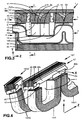
- la figure 6 représente schématiquement une machine à deux circuits magnétiques statoriques à entrefers cylindriques suivant la deuxième structure;
- la figure 7 représente schématiquement une machine à entrefers plans à mouvement de rotation ou de translation suivant la troisième ou la quatrième structure;
- la figure 8 est la coupe schématique d'un groupe motopropulseur thermique d'un véhicule, équipé d'une machine suivant l'invention et
- la figure 9 représente une machine à deux ensembles moteurs.
- Figure 1 is a partial section II of Figure 3, perpendicular to the axial direction Z of a rotary machine according to the invention, according to the first structure, with the axial magnetization arrangement of the permanent magnets and with an external rotor;
- Figure 2 is the limited section II of Figure 1;
- Figure 3 is section III-III of Figure 1;
- Figure 4 is a perspective view of a hoop rotor with radial magnetization in front of a stator arch with a partial representation of neighboring arcs;
- FIG. 5 is a diagram of the operation of the machine after a double curvature straightening;
- FIG. 6 schematically represents a machine with two magnetic stator circuits with cylindrical air gaps according to the second structure;
- FIG. 7 schematically represents a machine with plane air gaps with rotation or translation movement according to the third or fourth structure;
- FIG. 8 is the schematic section of a thermal powertrain of a vehicle, equipped with a machine according to the invention and
- FIG. 9 represents a machine with two engine assemblies.
Dans la configuration de la première structure, sur les figures 1 à 3, la machine 1 est constituée par un stator 2 et par un rotor 3 ayant pour rotation une première direction de déplacement circonférentielle X, par rapport au stator supposé fixe, le mouvement de rotation ayant un axe dans une deuxième direction Z qui est donc ici axiale. Le rotor 3 est ici extérieur au stator 2 dans une troisième direction Y qui est radiale, chacune de ces trois directions étant orthogonale aux autres .In the configuration of the first structure, in FIGS. 1 to 3, the
Le stator 2 comprend un circuit magnétique statorique 4 constitué par un assemblage dans la direction X d'arceaux statoriques 14 disposés chacun dans un plan perpendiculaire à la direction X sur une couronne 40. Chaque arceau 14 a, dans la direction Y, deux bras 15 à même calage angulaire autour de l'axe Z et terminés chacun par un pôle 6,6b saillant radialement vers le rotor. Ces arceaux sont positionnés sur la face extérieure de la couronne statorique 40.The
Le rotor 3 comprend un circuit magnétique rotorique 8 constitué par un assemblage dans la direction X d'arceaux rotoriques 16 disposés chacun dans un plan perpendiculaire à la direction X sur une couronne rotorique 41. Chaque arceau 16 a, dans la direction Y, deux pôles 11, 11b à même calage angulaire X orientés axialement vers le stator. Un pôle rotorique 11 est constitué par une première extrémité d'un demi-arceau rotorique 16/a ou 16/b, les deuxièmes extrémités de deux demi-arceaux 16/a et 16/b de chaque arceau 16 enserrant un aimant permanent respectif 42 à aimantation sensiblement axiale Z, contrairement à l'aimantation orientée tangentiellement que l'on connait pour les aimants permanents dits "enterrés" des moteurs synchrones axialement homopolaires. Chaque arceau 16 est donc constitué par l'ensemble 16/a,42 et 16/b fixé sur la face intérieure d'une couronne rotorique 41.The
Les paires de pôles statoriques 6,6b et rotoriques 11, 11b définissent entre eux deux rangées cylindriques 12 et 12b d'entrefers espacées selon la direction axiales Z, rendant la machine axialement hétéropolaire.The pairs of
Les arceaux statoriques et demi-arceaux rotoriques sont constitués chacun par un empilage de bandes de tôles cintrées suivant différents rayons autour d'axes de cintrage dont la direction est transversale à l'axe d'orientation des grains et à la direction axiale Z c'est à dire sensiblement parallèle à la direction X. Ces arceaux proviennent de préférence du sectionnement d'un tore enroulé et collé à partir d'une bande de tôle magnétique mince à grains orientés.The stator arches and rotor half arches each consist of a stack of strips of metal sheets bent along different radii around bending axes whose direction is transverse to the grain orientation axis and to the axial direction Z c ' is to say substantially parallel to the direction X. These arches preferably come from the sectioning of a toroid wound and glued from a strip of thin magnetic sheet with oriented grains.
La réalisation de la figure 1 comporte 30 arceaux statoriques 14 dont seulement 3 sont représentés et repérés de 14/30 à 14/2 ainsi que 40 arceaux rotoriques 16 dont seulement 4 sont représentés et repérés de 16/40 à 16/3.The embodiment of FIG. 1 comprises 30
Dans chaque rangée d'entrefers, les pôles statoriques 6 sont régulièrement répartis autour de l'axe Z, de même que pour les pôles rotoriques 11.In each row of air gaps, the
Les 30 arceaux statoriques 14 sont décomposés en un nombre g de groupes de q arceaux avec ici 5 groupes de chacun 6 arceaux successifs à calage angulaire croissant relativement à la direction X, excités chacun par une bobine 7 d'une des q phases. Il y a donc autant de phases que d'arceaux dans chaque groupe.The 30
A la figure 1, les sections des bobines sont repérées de F5 à B'1, les sections F'5 et A1 n'étant pas représentées. Les bobines 7 sont bobinées sur une carcasse 17.In FIG. 1, the sections of the coils are marked from F5 to B'1, the sections F'5 and A1 not being shown. The
L'excitation est faite en double alternance à partir d'un réseau alternatif polyphasé. Les sens de bobinage des bobines qui se succèdent le long de la direction de déplacement X sont alternés d'une bobine à sa voisine, comme symbolisé par une croix ou un point dans un cercle.The excitation is made in double alternation from a polyphase alternating network. The winding directions of the successive coils along the direction of movement X are alternated from one coil to its neighbor, as symbolized by a cross or a point in a circle.
En outre, relativement à un sens de déplacement le long de la direction de déplacement X, chaque bobine 7 est alimentée par une phase choisie pour avoir un déphasage électrique de 2π/q par rapport à la bobine précédente. Le déphasage d'excitation de chaque arceau par rapport au précédent cumule le déphasage électrique et celui π dû à l'alternance du sens de bobinage. Il est donc égal à 2π/q+π. Les arceaux d'un groupe sont donc hétérophasés.In addition, relative to a direction of movement along the direction of movement X , each
Chaque aimant permanent 42 produit sur les rangées d'entrefers 12 et 12b des polarités opposées. En outre, les polarités de deux aimants permanents angulairement voisins, repérés par les lettres N et S, donc qui se suivent le long de la direction de déplacement X, sont également opposées.Each
Pour retrouver le bon sens d'excitation tout le long du périmètre de l'élément statorique, il faut que le nombre d'arceaux 14 soit pair c'est à dire que l'un au moins des nombres q et g soit pair.To find the right sense of excitation all along the perimeter of the stator element, the number of
Dans les réalisations habituelles des machines à effet Vernier, dans un groupe de g pôles statoriques hétérophasés, il y a au rotor un pôle de plus ou de moins qu'au stator. Cependant, dans le cas de la machine suivant l'invention et avec un mouvement de rotation, cette disposition conduirait à inverser d'un groupe à l'autre les polarités respectives des aimants permanents par rapport aux ampèretours, provoquant des forces antagonistes d'un groupe à l'autre. Pour supprimer ce défaut, il faut qu'il y ait un nombre pair n d'arceaux rotoriques de plus ou de moins dans chacun des groupes de q arceaux statoriques 14 hétérophasés, avec n pair positif ou négatif.In the usual embodiments of Vernier effect machines, in a group of g heterophase stator poles, there is one pole more or less in the rotor than in the stator. However, in the case of the machine according to the invention and with a rotational movement, this arrangement would result in reversing from one group to another the respective polarities of the permanent magnets with respect to the amperes, causing antagonistic forces of a group to another. To remove this defect, there must be an even number n of rotor arcs more or less in each of the groups of
Pour réaliser cette condition, il faut que le rapport entre les pas statorique et rotorique soit égal à l'unité augmenté du nombre pair n divisé lui-même par le nombre de phases q, soit 1+n/q To achieve this condition, the ratio between the stator and rotor steps must be equal to the unit increased by the even number n divided itself by the number of phases q , i.e. 1 + n / q
Avec n=2, le nombre d'arceaux rotoriques est bien de 6x5+2x5=40.With n = 2, the number of rotor arches is indeed 6x5 + 2x5 = 40.
Avec une distribution progressive des phases sur les arceaux 14, le déphasage entre les courants d'excitation de deux pôles 6 voisins dans la direction X est de 2π/q, donnant des ampèretours de même direction en dehors des instants d'inversion de courant. Or comme les polarités des pôles rotoriques 11 s'inversent d'un pôle à son voisin, il faut que les déphasages entre pôles 6 voisins soient augmentés d'une demi-période, c'est à dire que le déphasage total soit de π+2π/q. On a vu ci dessus que cette condition est réalisée grâce à l'inversion du sens de bobinage d'une bobine 7 telle que A par rapport à sa voisine B.With a progressive distribution of the phases on the
Pour réaliser la condition d'alternance angulaire des polarités magnétiques des pôles 11, il faut que le nombre d'arceaux 16 soit pair, ce qui est réalisé quel que soit g du fait que n et le nombre d'arceaux 14 sont pairs.To achieve the condition of angular alternation of the magnetic polarities of the
On a choisi n=2 de façon à faciliter l'obtention d'une longueur dans la direction X d'un pôle rotorique 11 au moins sensiblement égale à celle d'un creux de denture entre deux pôles statoriques 6, pour des motifs exposés ultérieurement. On peut aussi avoir n=4 avec un grand nombre de phases q ou n=0 pour un générateur monophasé par couronne statorique.We chose n = 2 so as to facilitate obtaining a length in the direction X of a
Sur la figure 3, on a représenté dans la direction axiale Z plusieurs ensembles modulaires d'arceaux statoriques et rotoriques dans les couronnes 40 et 41. La construction peut donc être axialement modulaire. Elle peut aussi être diamétralement modulaire à peu de frais d'investissement en modifiant le nombre d'arceaux par couronne en fonction du diamètre choisi pour les couronnes.In Figure 3, there is shown in the axial direction Z several modular sets of stator and rotor arcs in the
On voit que deux bras 15 voisins d'arceaux statoriques 14 et 14b à même calage angulaire, formant ensemble un circuit magnétique élémentaire en forme de E, peuvent être excités par une même bobine 7 autour de la barre centrale du E.It can be seen that two
Sur les figures 1 à 3, on voit que des conduits 19 traversent le circuit magnétique statorique 4 chacun à proximité de l'emplacement des bobines 7 entre deux circuits magnétiques élémentaires en E angulairement voisins de façon à permettre la circulation d'un fluide de réfrigération.In FIGS. 1 to 3, it can be seen that
Chaque conduit 19 est de préférence constitué par l'assemblage de deux demi-coquilles 43 et 43b symétriques (seul le conduit entre les arceaux 14/30 et 14/1 est représenté).Each
Chaque conduit 19 s'étend globalement dans un plan transversal à la direction X. Le parcours d'un conduit 19 commence ici par un emmanchement dans une ouverture d'une première face latérale 44 terminant la couronne 40, au voisinage d'une rangée d'entrefers 12, suivi d'un trajet radial entre bobines 7 et bras d'arceaux 14, suivi d'un trajet axial le long de la couronne 40, suivi d'un nouveau trajet radial entre bobines 7 et bras d'arceaux 14b, les deux trajets radiaux et le trajet axial formant ensemble un lobe 59 (figure 3) contournant les deux bobines adjacentes (F'5 et Al non représentées) par le côté de ces bobines qui est opposé aux entrefers. Ce lobe est suivi soit d'un nouveau parcours identique dans d'autres ensembles modulaires statoriques axialement voisins, soit d'un trajet axial débouchant dans une ouverture de la deuxième face latérale de la couronne 40.Each
Les arceaux sont entaillés à leurs bases et les couronnes 40 et 41 sont mortaisées de façon à permettre un assemblage à queue d'aronde en glissant axialement les arceaux dans les mortaises 60 (figure 1).The arches are notched at their bases and the
Après avoir mis en place les conduits 19 et les bobines 7, on procède, avec une matière plastique 18, à un surmoulage de la couronne statorique 40 ainsi équipée et limitée par les faces latérales 44, ainsi qu'à un surmoulage de la couronne rotorique 41 également équipée d'arceaux composites 16 et limitée par des faces latérales 45 (seul l'élément rotorique 3 est représenté surmoulé). Les couronnes peuvent être tronçonnées dans un profilé.After having put in place the
Les arceaux ayant des cotes relativement peu précises, pour que les surfaces d'entrefers soient positionnées avec précision, l'assemblage à queues d'aronde est fait avec un certain degré de liberté et pendant l'opération de surmoulage le positionnement des surfaces d'entrefers est obtenu par une attraction magnétique desdites surfaces au moyen d'un agencement convenable de la partie en vis-à-vis du moule de surmoulage, cette partie comportant des pôles ayant chacun exactement la position d'une surface d'entrefer et étant chacun relié à un aimant permanent ou à un électro-aimant.The hoops having relatively imprecise dimensions, so that the air gap surfaces are positioned with precision, the dovetail assembly is done with a certain degree of freedom and during the overmolding operation the positioning of the air gaps is obtained by a magnetic attraction of said surfaces by means of a suitable arrangement of the part facing the mold. overmolding, this part comprising poles each having exactly the position of an airgap surface and each being connected to a permanent magnet or to an electromagnet.
Dans la machine décrite dans les figures 1 à 3, au lieu d'avoir un seul aimant permanent 42 à aimantation axiale Z par arceau 16, on peut mettre deux aimants permanents 46 et 46b à aimantation radiale Y en forme de tuile dont une première face joue directement le rôle de surface d'entrefer et dont la deuxième face est reliée par une barre magnétique 47 à la surface homologue de l'aimant permanent à même calage angulaire X comme représenté sur la figure 4, en constituant l'équivalent d'un arceau rotorique 16 en face d'un arceau statorique 14. Sur les figures 1 et 3, il suffit de remplacer les pièces 16/a,42 et 16/b par l'ensemble 46,47 et 46b de la figure 4.In the machine described in FIGS. 1 to 3, instead of having a single
Les inductions qu'on peut obtenir sur une surface d'aimant permanent sont moins élevées que celles qu'on peut avoir avec du fer, et avec des entrefers moins précis. On peut cependant rectifier le rotor après surmoulage et la diminution de l'induction peut être compensée par une augmentation de la surface polaire d'un aimant permanent ainsi que celle d'un pôle 6 comme on le verra sur la figure 6. Les flux de fuite sont par ailleurs plus faibles qu'avec des pièces polaires.The inductions that can be obtained on a permanent magnet surface are lower than those that can be obtained with iron, and with less precise air gaps. However, the rotor can be rectified after overmolding and the reduction in induction can be compensated by an increase in the polar surface of a permanent magnet as well as that of a
Les pièces 16/a,16/b et 47 peuvent être feuilletées avec des tôles jusqu'à dix fois plus épaisses que celles des arceaux 14 du fait des variations de flux plus faibles et unidirectionnelles. En particulier la barre 47 est ici constituée par des tôles planes 48 empilées dans la direction X, emprisonnant la deuxième face des aimants permanents 46 et 46b. Chaque tôle d'extrémité 48b de l'empilage est plus courte au niveau de la couronne 41 et la tôle suivante 48c est cambrée dans l'espace ainsi libre pour former une queue d'aronde capable d'être engagée dans la mortaise 60 de la couronne 41 (figure 1).The
Sur la figure 4, on a également partiellement représenté un arceau statorique 14b/1 axialement voisin de l'arceau 14/1 avec leur courant commun d'excitation i ainsi qu'un arceau statorique 14/30 angulairement voisin avec son arceau rotorique 16/40.In FIG. 4, there is also partially shown a
La figure 5 permet de comprendre le fonctionnement en moteur d'une telle machine, dans la disposition à aimantation radiale. Pour illustrer un cas où q est impair, on a choisi q=9 g=4 et n=2. On a représenté un peu plus qu'un groupe d'arceaux 14, de 14/36 à 14/10 séparés par les rangées d'entrefers 12 et 12b d'aimants permanents 46 et 46b constituant les pôles de 16/44 à 16/11.FIG. 5 makes it possible to understand the engine operation of such a machine, in the arrangement with radial magnetization. To illustrate a case where q is odd, we chose q = 9 g = 4 and n = 2 . A little more than a group of
La courbure dans la direction X des rangées d'entrefers a été redressée pour être rectiligne et les boucles des circuits magnétiques élémentaires d'arceaux ont été chacune fictivement sectionnée au niveau des barres 47 et également redressée de part et d'autre du fond des arceaux 14 de manière à confondre les directions Y et Z.The curvature in the direction X of the rows of air gaps has been straightened to be rectilinear and the loops of the elementary magnetic circuits of arcs were each fictitiously cut at the level of the
Un point ou une croix dans un cercle indiquent le sens de bobinage 7 dans les sections de bobines I'4,A1,A'1...I'1 et A2 et les lettres N et S indiquent les polarités des surfaces des aimants permanents 46 et 46b.A point or a cross in a circle indicates the winding
On a également tracé entre 14/1 et 14/10 la courbe 49 de la forme d'onde d'une période du courant de la phase A ayant ici une forme trapézoïdale à 12 rampes avec leur maillage. Chaque rampe occupe un angle électrique identique de façon à avoir à chaque instant une somme nulle de tous les courants instantanés, ce qui facilite la réalisation de l'alimentation électronique. La pente de la rampe au voisinage de l'inversion de courant est plus forte que celle qu'on aurait eue avec une onde sinusoïdale de même amplitude de crête.The
Des flèches représentent l'amplitude (relevée sur la courbe 49) et le sens des ampèretours dans chaque arceau 14 à l'instant où le rotor a la position représentée et des lignes de flux ont été tracées symboliquement dans les entrefers élargis, montrant le sens des forces d'attraction. Bien entendu, ces lignes se referment en dehors de la figure entre les extrémités sectionnées des barres 47.Arrows represent the amplitude (noted on curve 49) and the direction of the amperes in each
Lorsqu'un aimant permanent se trouve au voisinage d'un pôle statorique de même polarité (cas des pôles 16/4 et 16/9), on remarque que le flux de l'aimant peut être transféré transversalement vers les arceaux rotoriques voisins en évitant d'avoir des forces d'attraction antagonistes dans des entrefers en train de s'ouvrir. Il est aussi souhaitable d'éviter que le flux d'un aimant permanent ne puisse se boucler à certains instants que par des · réluctances d'air.When a permanent magnet is in the vicinity of a stator pole of the same polarity (case of
C'est pour favoriser ce transfert rapide qu'on a une forte pente de l'onde 49 et qu'on a fixé la longueur de l'arc 11 à au moins le creux de denture statorique. Cette condition est difficile à obtenir avec n négatif ou avec q trop petit. De plus, avec q au moins égal à 6, les lignes de force dans un entrefer sont plus courtes.It is to promote this rapid transfer that there is a steep slope of the
Le fonctionnement de la machine est donc semblable à celui d'une machine synchrone dans lequel la composition vectorielle du champ tournant est remplacée par une composition discrète, procurant par ailleurs les avantages suivants:The operation of the machine is therefore similar to that of a synchronous machine in which the vectorial composition of the rotating field is replaced by a discrete composition, also providing the following advantages:
Fonctionnement pas-à-pas indexable avec couple à l'arrêt sans excitation. Tôles minces (jusqu'à 0,05mm) enroulées, à grains orientés dans la direction du flux, circuit court et arrondi sans joint, pertes de matière négligeables. Tôles abordant un entrefer chacune progressivement et toutes simultanément. Entrefers à faible allongement minimisant l'effet des franges périphériques, augmentant les ampèretours et diminuant le poids de cuivre à section de fer constante, pas de dérivation de flux vers d'autres phases. Bobinage sur carcasse, réfrigération. Assemblage par surmoulage. Double modularité. Pas d'outillage de découpe.Indexable step-by-step operation with torque stopped without excitation. Thin sheets (up to 0.05mm) rolled, grain oriented in the direction of flow, short and rounded circuit without joint, negligible loss of material. Sheets approaching an air gap each gradually and all simultaneously. Low elongation air gaps minimizing the effect of peripheral fringes, increasing amperes and decreasing the weight of copper with constant iron section, no flow diversion to other phases. Winding on carcass, refrigeration. Assembly by overmolding. Double modularity. No cutting tools.
Sur la figure 6 concernant la deuxième structure à mouvement de rotation, on a représenté symboliquement (sans les surmoulages) un stator 2 constitué par deux circuits magnétiques statoriques 4 et 4' symétriques et concentriques par rapport à une direction axiale Z, les arceaux de chaque circuit étant fixés par un bras 15 sur un support statorique 50,50' en forme de disque radialement mortaisé, les pôles 6 et 6' se faisant face dans une direction radiale Y. L'élément rotorique 3 est situé entre ces circuits 4 et 4' et est constitué par un support rotorique 51 en forme de couronne tournant autour d'un axe de direction Z et emprisonnant des aimants permanents 46 et 46b en forme de tuile ayant une aimantation de direction radiale Y de façon à ce que les deux faces polaires de chaque aimant permanent jouent chacune le rôle d'une surface d'entrefer cylindrique avec l'un des circuits 4,4'.In FIG. 6 concerning the second structure with rotational movement, there is shown symbolically (without the overmoldings) a
Le support 51 peut être réalisé en métal léger comportant des logements fendus pour recevoir les aimants permanents avant un surmoulage.The
Au lieu d'avoir une forme en U à bras parallèles, les arceaux statoriques 14 et 14' ont ici une forme en C avec des pôles 6,6b rapprochés. Du fait du sectionnement oblique par rapport au plan des tôles, les surfaces d'entrefers sont augmentées. Cela permet de compenser la relativement plus faible induction des aimants permanents. La force tangentielle est aussi proportionnelle à la longueur des bords d'attaque des surfaces d'entrefers.Instead of having a U shape with parallel arms, the
La carcasse de bobine 17 est alors réalisée en deux parties symétriques et le bobinage est effectué d'une manière connue à amenée de fil tournante sur un ensemble noyau-bobine non-tournant mais oscillant ici autour de l'axe de symétrie des surfaces d'entrefers de façon à bien remplir le centre de la forme en C.The
Un circuit magnétique élémentaire comporte donc quatre entrefers 12,12b,12' et 12b' en série, de forme cylindrique et l'inertie du rotor 3 est réduite, ce qui est intéressant en robotique.An elementary magnetic circuit therefore comprises four
Les moyens de roulement doivent être reportés latéralement. L'élément statorique 2 peut comporter un deuxième ensemble de circuits 4,4' symétrique du premier, l'élément rotorique 3 ayant alors une forme en T comme sur la figure 5 du EP A 0553582 dont la structure est cependant différente.The rolling means must be transferred laterally. The
La troisième structure est représentée sur la figure 7: deux circuits magnétiques statoriques symétriques 4 et 4' sont disposés perpendiculairement à une direction axiale Z, les arceaux 14 de chaque circuit étant fixés par leur fond sur des supports statoriques 50,50' en forme de disque radialement mortaisé, les bras 15 d'un arceau étant ainsi alignés dans une direction Y qui est radiale. Les pôles statoriques 6,6' se font face dans la direction Z. L'élément rotorique 3 est situé entre ces circuits 4 et 4' et est constitué par un support rotorique 51 en forme de disque tournant autour d'un axe de direction Z et emprisonnant des aimants parallélépipédiques 42 et 42b ayant une aimantation de direction axiale Z de façon à ce que les deux faces de chaque aimant permanent jouent chacune le rôle d'une surface d'entrefer plane avec l'un des circuits 4,4', la machine étant ainsi radialement hétéropolaire.The third structure is shown in Figure 7: two symmetrical
Avec des entrefers plans, il faut prévoir des moyens de réglage des entrefers en tenant compte des forces d'attractions axiales. Pour ajuster l'écartement des circuits 4 et 4',compte tenu des tolérances d'épaisseur des aimants permanents, on a prévu une culasse 52 ayant à ses extrémités intérieures des taraudages à pas inversés s'engageant sur la périphérie filetée des disques statoriques 50,50'. Après avoir annulé les entrefers par vissage de la culasse 52, une rotation déterminée en sens inverse fixe la somme des entrefers. Prenant appui sur les disques 50,50', des butées réglables 53 telles que des vis agissent sur des roulements à butée 54 enserrant le disque rotorique 51 monté à coulisse en permettant de répartir d'une manière égale cette somme sur chaque plan d'entrefer.With plane air gaps, it is necessary to provide means for adjusting the air gaps taking account of the forces of axial attraction. To adjust the spacing of
Si nécessaire, on peut disposer un autre ensemble 53,54 de butées et roulements à l'extérieur des arceaux 14,14'.If necessary, another set 53,54 of stops and bearings can be placed outside the
On peut d'autre part considérer que la figure 7 représente aussi la quatrième structure dans laquelle le support rotorique 51 est un curseur en forme de barre rectiligne se déplaçant par translation dans la direction X sur une course limitée, le mouvement rotorique pouvant à la limite être considéré comme un mouvement de translation. Les supports statoriques 50,50' sont alors aussi des barres rectilignes portant chacune au moins un groupe g d'arceaux statoriques hétérophasés.On the other hand, it can be considered that FIG. 7 also represents the fourth structure in which the
Dans une application en traction, une machine à rotor extérieur peut être logée dans le moyeu d'une roue d'un véhicule à propulsion électrique.In a traction application, an external rotor machine can be housed in the hub of a wheel of an electrically propelled vehicle.
La figure 8 représente une autre application de la machine à un véhicule à propulsion mixte: On a représenté un moteur thermique 30 relié à un premier plateau mobile 31 d'un embrayage 32 dont le deuxième plateau 33 est relié à une boite de vitesse 34 actionnant elle-même les roues motrices du véhicule.Figure 8 shows another application of the machine to a vehicle with mixed propulsion: An
Une machine 1 rotative suivant l'invention à rotor intérieur au stator a son circuit magnétique rotorique 8 fixé sur la périphérie du deuxième plateau 33 de l'embrayage 32. Cette machine remplit les fonctions suivantes:
Démarrage du moteur thermique, recharge des accumulateurs, propulsion urbaine électrique, freinage à récupération d'énergie, augmentation de l'accélération à moteur thermique, marche arrière électrique et recharge des accumulateurs au domicile. On a donc un fonctionnement hybride parallèle.A
Starting the combustion engine, recharging the accumulators, electric urban propulsion, regenerative braking, increasing acceleration with the combustion engine, electric reverse and recharging the accumulators at home. We therefore have a parallel hybrid operation.
L'implantation de cette machine sur un véhicule peut se faire sans augmentation de la longueur d'arbre de l'ensemble propulseur et sans adjonction d'un autre organe de transmission, en utilisant les moyens de roulement de l'embrayage.The installation of this machine on a vehicle can be done without increasing the length of the shaft of the propulsion unit and without adding another transmission member, by using the clutch rolling means.
Un deuxième ensemble modulaire axialement décalé peut être décalé angulairement et électriquement en fonctionnement moteur de façon à lisser la courbe globale du couple. Ce deuxième ensemble peut aussi être alimenté séparément de façon à augmenter la sécurité de fonctionnement.A second axially offset modular assembly can be angularly and electrically offset in engine operation so as to smooth the overall curve of the torque. This second set can also be supplied separately so as to increase operating safety.
Sur la figure 9, un circuit magnétique statorique commun 4 actionne deux demi-circuits magnétiques rotoriques 8a et 8b formant deux ensembles moteurs 70a 70b munis chacun d'un arbre 71a 71b. Ces arbres peuvent être liés entre eux par un dispositif de secours 72.In FIG. 9, a common stator
Chaque arbre peut ainsi entraîner une roue d'un véhicule. Certains arceaux statoriques peuvent être supprimés pour abaisser le plancher du véhicule.Each shaft can thus drive a wheel of a vehicle. Some stator bars can be removed to lower the vehicle floor.
Pour procéder au calcul et à l'optimisation des performances des machines axialement homopolaires dans lesquelles les flux sont situés dans un plan unique contenant la direction X et perpendiculaire à la direction Z, on peut utiliser un logiciel permettant de calculer et de représenter des grandeurs magnétiques au moyen d'un maillage d'un circuit magnétique représenté sur une figure plane en faisant varier différents paramètres magnétiques et dimensionnels, dont le déplacement X.To calculate and optimize the performance of axially zero sequence machines in which the fluxes are located in a single plane containing the X direction and perpendicular to the Z direction, software can be used to calculate and represent magnetic quantities by means of a mesh of a magnetic circuit represented on a plane figure by varying different magnetic and dimensional parameters, including displacement X.
Dans une machine suivant l'invention, comme la direction X du déplacement est perpendiculaire aux lignes de flux qui elles mêmes ne sont pas situées dans un même plan, il faudrait utiliser un logiciel travaillant dans trois dimensions, dont l'emploi est difficile et onéreux.In a machine according to the invention, since the direction X of the displacement is perpendicular to the flow lines which themselves are not located in the same plane, it would be necessary to use a software working in three dimensions, the use of which is difficult and expensive .
Sur la figure 5, on a sectionné fictivement et on a redressé la courbure de quelques circuits magnétiques élémentaires voisins comprenant chacun au moins un arceau, un aimant permanent avec ses pièces de liaison magnétique et un entrefer.In FIG. 5, we have fictitiously sectioned and the curvature of a few neighboring elementary magnetic circuits has been straightened, each comprising at least one hoop, a permanent magnet with its magnetic connection parts and an air gap.
Si de plus on réunit fictivement avec une réluctance nulle les extrémités sectionnées homologues de chaque circuit élémentaire, cette représentation plane permet de procéder au calcul et à l'optimisation de la machine en utilisant simplement un logiciel à deux dimensions.If in addition we fictitiously unite with zero reluctance the homologous sectioned ends of each elementary circuit, this plane representation allows the machine to be calculated and optimized by simply using two-dimensional software.
Bien entendu, des modifications peuvent être apportées aux descriptions ci-dessus sans sortir du domaine revendiqué.Of course, modifications can be made to the above descriptions without departing from the claimed domain.
A titre d'exemples, la surface polaire d'un aimant permanent 42 peut être augmentée en inclinant son axe par rapport à la direction axiale Z.By way of example, the pole surface of a
Avec un mouvement d'amplitude limitée, le premier organe 2 peut se déplacer par rapport au deuxième 3.With a movement of limited amplitude, the
Un effet dit de skewing peut être obtenu avec un pas de pôles légèrement irrégulier mais en moyenne constant.A so-called skewing effect can be obtained with a slightly irregular pole pitch but on average constant.
Claims (23)
Applications Claiming Priority (2)
| Application Number | Priority Date | Filing Date | Title |
|---|---|---|---|
| FR9601784A FR2744855B1 (en) | 1996-02-14 | 1996-02-14 | DYNAMO-ELECTRIC MACHINE WITH VARIABLE HYBRID RELUCTANCE WITH VERNIER EFFECT AND METHOD OF MANUFACTURE AND CALCULATION |
| FR9601784 | 1996-02-14 |
Publications (2)
| Publication Number | Publication Date |
|---|---|
| EP0790695A1 true EP0790695A1 (en) | 1997-08-20 |
| EP0790695B1 EP0790695B1 (en) | 2000-10-25 |
Family
ID=9489164
Family Applications (1)
| Application Number | Title | Priority Date | Filing Date |
|---|---|---|---|
| EP97400333A Expired - Lifetime EP0790695B1 (en) | 1996-02-14 | 1997-02-14 | Hybrid dynamo-electric variable reluctance machine and manufacturing and calculation method |
Country Status (3)
| Country | Link |
|---|---|
| EP (1) | EP0790695B1 (en) |
| DE (1) | DE69703364T2 (en) |
| FR (1) | FR2744855B1 (en) |
Cited By (12)
| Publication number | Priority date | Publication date | Assignee | Title |
|---|---|---|---|---|
| EP0942517A3 (en) * | 1998-03-03 | 2001-03-07 | DaimlerChrysler AG | Transverse flux machine |
| WO2001047089A3 (en) * | 1999-12-21 | 2001-12-13 | Richard Fletcher | Electronically commutated electrical machine |
| DE10037787A1 (en) * | 2000-08-03 | 2002-03-14 | Landert Motoren Ag | Permanent magnet excited synchronous machine e.g. general purpose drive motors, has external rotor design with external rotor joined rotationally-rigidly to rotatable shaft, around common axis |
| WO2003030333A3 (en) * | 2001-10-01 | 2003-06-19 | Wavecrest Lab Llc | Rotary electric motor having axially aligned stator poles and/or rotor poles |
| WO2003067740A1 (en) * | 2002-02-07 | 2003-08-14 | Wavecrest Laboratories, Llc | Rotary electric motor having at least three axially aligned stator poles and/or rotor poles |
| EP1394926A1 (en) * | 2002-09-02 | 2004-03-03 | Schärer Schweiter Mettler AG | Method for producing a stator of a stepping motor having a permanent magnetic disc type rotor, stator and motor produced according to this method |
| US6777851B2 (en) | 2001-10-01 | 2004-08-17 | Wavecrest Laboratories, Llc | Generator having axially aligned stator poles and/or rotor poles |
| FR2865077A1 (en) * | 2004-01-08 | 2005-07-15 | Spirelec | Electric actuator or generator device for bicycle, has excitation/inducing conductors with active sections placed between thin sheets that are placed parallel to median planes of magnetic jumpers so that magnetic flux flows in median planes |
| US7605515B2 (en) | 2004-05-06 | 2009-10-20 | Gerard Koehler | Variable reluctance dynamo-electric rotary machine provided with united magnetic, electric and polarising circuits and method for production thereof |
| US7635932B2 (en) | 2004-08-18 | 2009-12-22 | Bluwav Systems, Llc | Dynamoelectric machine having heat pipes embedded in stator core |
| DE19934936B4 (en) * | 1998-07-28 | 2011-06-22 | Schaeffler Technologies GmbH & Co. KG, 91074 | powertrain |
| WO2017148825A1 (en) * | 2016-03-04 | 2017-09-08 | Lenze Drives Gmbh | Vernier external rotor machine and motor system |
Families Citing this family (3)
| Publication number | Priority date | Publication date | Assignee | Title |
|---|---|---|---|---|
| US7687945B2 (en) | 2004-09-25 | 2010-03-30 | Bluwav Systems LLC. | Method and system for cooling a motor or motor enclosure |
| EP2413482A1 (en) * | 2010-07-30 | 2012-02-01 | Siemens Aktiengesellschaft | Airplane |
| JP6134126B2 (en) * | 2012-11-20 | 2017-05-24 | 株式会社東芝 | Rotating electric machine and vehicle |
Citations (8)
| Publication number | Priority date | Publication date | Assignee | Title |
|---|---|---|---|---|
| DE2923052A1 (en) * | 1979-06-07 | 1980-12-18 | Werner Tesch | Motor for electrically driven vehicle - has inner and outer permanent magnets on drive shaft and armature windings between |
| EP0155877A1 (en) * | 1984-02-29 | 1985-09-25 | Alsthom | Electrodynamic Vernier machine |
| WO1991020120A1 (en) * | 1990-06-11 | 1991-12-26 | Peter Michael Nahirney | Direct current motor utilizing back electromotive force |
| FR2685566A1 (en) * | 1991-12-23 | 1993-06-25 | Koehler Gerard | Dynamo-electric machine consisting of sectors juxtaposed along the direction of movement, and method of manufacturing the said sectors |
| WO1994006198A1 (en) * | 1992-09-02 | 1994-03-17 | Electric Power Research Institute, Inc. | Quasi square-wave back-emf permanent magnet ac machines with five or more phases |
| US5365137A (en) * | 1990-11-01 | 1994-11-15 | Dynamic Systems International Inc. | Electric motor |
| EP0677914A1 (en) * | 1994-04-15 | 1995-10-18 | Herbert Prof. Dr. Weh | Machine with transverse flux |
| US5475277A (en) * | 1993-07-21 | 1995-12-12 | Fluidmaster, Inc. | Differential torque motor |
-
1996
- 1996-02-14 FR FR9601784A patent/FR2744855B1/en not_active Expired - Fee Related
-
1997
- 1997-02-14 DE DE69703364T patent/DE69703364T2/en not_active Expired - Fee Related
- 1997-02-14 EP EP97400333A patent/EP0790695B1/en not_active Expired - Lifetime
Patent Citations (9)
| Publication number | Priority date | Publication date | Assignee | Title |
|---|---|---|---|---|
| DE2923052A1 (en) * | 1979-06-07 | 1980-12-18 | Werner Tesch | Motor for electrically driven vehicle - has inner and outer permanent magnets on drive shaft and armature windings between |
| EP0155877A1 (en) * | 1984-02-29 | 1985-09-25 | Alsthom | Electrodynamic Vernier machine |
| WO1991020120A1 (en) * | 1990-06-11 | 1991-12-26 | Peter Michael Nahirney | Direct current motor utilizing back electromotive force |
| US5365137A (en) * | 1990-11-01 | 1994-11-15 | Dynamic Systems International Inc. | Electric motor |
| FR2685566A1 (en) * | 1991-12-23 | 1993-06-25 | Koehler Gerard | Dynamo-electric machine consisting of sectors juxtaposed along the direction of movement, and method of manufacturing the said sectors |
| EP0553582A2 (en) * | 1991-12-23 | 1993-08-04 | Radio-Energie S.A. | Dynamoelectric machine comprising sectors juxtaposed in the direction of movement and method of making such sectors |
| WO1994006198A1 (en) * | 1992-09-02 | 1994-03-17 | Electric Power Research Institute, Inc. | Quasi square-wave back-emf permanent magnet ac machines with five or more phases |
| US5475277A (en) * | 1993-07-21 | 1995-12-12 | Fluidmaster, Inc. | Differential torque motor |
| EP0677914A1 (en) * | 1994-04-15 | 1995-10-18 | Herbert Prof. Dr. Weh | Machine with transverse flux |
Non-Patent Citations (3)
| Title |
|---|
| 10th Conference on Computation of Electromagnetic Fields (COMPUMAG'95), Berlin, DE, 10-13 July 1995 * |
| DATABASE INSPEC INSTITUTE OF ELECTRICAL ENGINEERS, STEVENAGE, GB; XP002031329 * |
| SADOWSKI ET AL., IEEE TRANSACTIONS ON MAGNETICS, vol. 32, no. 3, May 1996 (1996-05-01), pages 1086 - 1089, XP000609583 * |
Cited By (19)
| Publication number | Priority date | Publication date | Assignee | Title |
|---|---|---|---|---|
| EP0942517A3 (en) * | 1998-03-03 | 2001-03-07 | DaimlerChrysler AG | Transverse flux machine |
| DE19934936B4 (en) * | 1998-07-28 | 2011-06-22 | Schaeffler Technologies GmbH & Co. KG, 91074 | powertrain |
| WO2001047089A3 (en) * | 1999-12-21 | 2001-12-13 | Richard Fletcher | Electronically commutated electrical machine |
| DE10037787B4 (en) * | 2000-08-03 | 2005-04-14 | Landert-Motoren-AG, Bülach | Permanent magnet synchronous machine |
| DE10037787A1 (en) * | 2000-08-03 | 2002-03-14 | Landert Motoren Ag | Permanent magnet excited synchronous machine e.g. general purpose drive motors, has external rotor design with external rotor joined rotationally-rigidly to rotatable shaft, around common axis |
| KR100850813B1 (en) * | 2001-10-01 | 2008-08-06 | 웨이브크레스트 래버러토리스, 엘엘씨 | Rotary electric motor having axially aligned stator poles and/or rotor poles |
| US6617746B1 (en) | 2001-10-01 | 2003-09-09 | Wavecrest Laboratories, Llc | Rotary electric motor having axially aligned stator poles and/or rotor poles |
| WO2003030333A3 (en) * | 2001-10-01 | 2003-06-19 | Wavecrest Lab Llc | Rotary electric motor having axially aligned stator poles and/or rotor poles |
| US6777851B2 (en) | 2001-10-01 | 2004-08-17 | Wavecrest Laboratories, Llc | Generator having axially aligned stator poles and/or rotor poles |
| WO2003067740A1 (en) * | 2002-02-07 | 2003-08-14 | Wavecrest Laboratories, Llc | Rotary electric motor having at least three axially aligned stator poles and/or rotor poles |
| US6710502B2 (en) | 2002-02-07 | 2004-03-23 | Wavecrest Laboratories, Llc | Rotary electric motor having at least three axially aligned stator poles and/or rotor poles |
| EP1394926A1 (en) * | 2002-09-02 | 2004-03-03 | Schärer Schweiter Mettler AG | Method for producing a stator of a stepping motor having a permanent magnetic disc type rotor, stator and motor produced according to this method |
| WO2004105215A1 (en) * | 2003-05-19 | 2004-12-02 | Wavecrest Laboratories Llc | Generator having axially aligned stator poles and/or rotor poles |
| FR2865077A1 (en) * | 2004-01-08 | 2005-07-15 | Spirelec | Electric actuator or generator device for bicycle, has excitation/inducing conductors with active sections placed between thin sheets that are placed parallel to median planes of magnetic jumpers so that magnetic flux flows in median planes |
| US7605515B2 (en) | 2004-05-06 | 2009-10-20 | Gerard Koehler | Variable reluctance dynamo-electric rotary machine provided with united magnetic, electric and polarising circuits and method for production thereof |
| US7635932B2 (en) | 2004-08-18 | 2009-12-22 | Bluwav Systems, Llc | Dynamoelectric machine having heat pipes embedded in stator core |
| WO2017148825A1 (en) * | 2016-03-04 | 2017-09-08 | Lenze Drives Gmbh | Vernier external rotor machine and motor system |
| CN108781009A (en) * | 2016-03-04 | 2018-11-09 | 伦策驱动有限公司 | Finely tune outer rotor machine and electric motor system |
| US11296579B2 (en) | 2016-03-04 | 2022-04-05 | Lenze Drives Gmbh | Vernier external rotor machine and motor system |
Also Published As
| Publication number | Publication date |
|---|---|
| EP0790695B1 (en) | 2000-10-25 |
| FR2744855B1 (en) | 1998-04-17 |
| DE69703364D1 (en) | 2000-11-30 |
| FR2744855A1 (en) | 1997-08-14 |
| DE69703364T2 (en) | 2001-05-17 |
Similar Documents
| Publication | Publication Date | Title |
|---|---|---|
| EP0540550B1 (en) | Dynamo-electric machine having cross-flux sectors | |
| EP0790695B1 (en) | Hybrid dynamo-electric variable reluctance machine and manufacturing and calculation method | |
| EP0909010B1 (en) | Electrical machine with flux commutation, particularly alternator for vehicle | |
| FR2762158A1 (en) | BRUSHED POLYPHASE-FREE MACHINE, IN PARTICULAR ALTERNATOR OF A MOTOR VEHICLE | |
| WO2005122367A1 (en) | Variable reluctance dynamo electric machine provided with united magnetic, electric and polarising circuits and method for production thereof | |
| FR2960109A1 (en) | PERMANENT MAGNET MOTOR WITH CONSISTENT POLE | |
| EP1236263B1 (en) | Motor/generator with energised reluctance and coil in the air gap | |
| EP0942510A1 (en) | Double excitation electrical machine, in particular an alternator for a motor vehicle | |
| FR2563059A1 (en) | VERNIER ELECTRODYNAMIC MACHINE | |
| EP2763296B1 (en) | Electrical machine having intermediate parts with a plurality of air gaps and 3D magnetic flux | |
| EP2599197B1 (en) | Synchronous rotary electric machine having hybrid-excitation rotor | |
| EP0553582B1 (en) | Dynamoelectric machine comprising sectors juxtaposed in the direction of movement and method of making such sectors | |
| EP0866539A1 (en) | Electric rotating machine excited by coils, permanent magnets or double excitation | |
| EP0221594A1 (en) | Motor with a direct-current supply | |
| EP0143029B1 (en) | Stepping motor of the hybrid multiphase-type and its control device | |
| WO2015049467A2 (en) | Multiphase electric rotating machine with at least five phases | |
| FR3008539A1 (en) | ELECTROMAGNETIC ACTUATOR POLYENTREFERS WITH PERMANENT MAGNETS AND WINDING ELEMENTS WITHOUT IRON | |
| WO2014122374A1 (en) | Electromagnetic motor or generator with a plurality of air gaps having permanent magnets and ironless winding element | |
| EP1130748A1 (en) | Electrical transversal flux machine with a starlike coreplates | |
| EP3017526A2 (en) | Automotive vehicle starter | |
| WO2005076434A2 (en) | Electric actuator or electric generator device responsive to magnetic repulsion force | |
| FR2727263A1 (en) | VARIABLE TYPE VARIABLE RELUCTANCE ROTATING DYNAMO-ELECTRIC MACHINE AND METHOD FOR MANUFACTURING THE SAME | |
| FR2862166A1 (en) | Dynamo-electric machine for e.g. wind turbine, has magnetic polarization and coupling unit including magnetic polarization unit assigning cap plates with polarity for polarizing rotor poles according to polarization conditions | |
| FR3162326A1 (en) | Permanent magnet rotor | |
| FR2716046A1 (en) | Rotating electric machine with global winding. |
Legal Events
| Date | Code | Title | Description |
|---|---|---|---|
| PUAI | Public reference made under article 153(3) epc to a published international application that has entered the european phase |
Free format text: ORIGINAL CODE: 0009012 |
|
| AK | Designated contracting states |
Kind code of ref document: A1 Designated state(s): DE GB IT |
|
| 17P | Request for examination filed |
Effective date: 19980213 |
|
| GRAG | Despatch of communication of intention to grant |
Free format text: ORIGINAL CODE: EPIDOS AGRA |
|
| 17Q | First examination report despatched |
Effective date: 19990702 |
|
| GRAG | Despatch of communication of intention to grant |
Free format text: ORIGINAL CODE: EPIDOS AGRA |
|
| GRAG | Despatch of communication of intention to grant |
Free format text: ORIGINAL CODE: EPIDOS AGRA |
|
| GRAH | Despatch of communication of intention to grant a patent |
Free format text: ORIGINAL CODE: EPIDOS IGRA |
|
| GRAH | Despatch of communication of intention to grant a patent |
Free format text: ORIGINAL CODE: EPIDOS IGRA |
|
| GRAA | (expected) grant |
Free format text: ORIGINAL CODE: 0009210 |
|
| AK | Designated contracting states |
Kind code of ref document: B1 Designated state(s): DE GB IT |
|
| PG25 | Lapsed in a contracting state [announced via postgrant information from national office to epo] |
Ref country code: IT Free format text: LAPSE BECAUSE OF FAILURE TO SUBMIT A TRANSLATION OF THE DESCRIPTION OR TO PAY THE FEE WITHIN THE PRESCRIBED TIME-LIMIT;WARNING: LAPSES OF ITALIAN PATENTS WITH EFFECTIVE DATE BEFORE 2007 MAY HAVE OCCURRED AT ANY TIME BEFORE 2007. THE CORRECT EFFECTIVE DATE MAY BE DIFFERENT FROM THE ONE RECORDED. Effective date: 20001025 |
|
| REF | Corresponds to: |
Ref document number: 69703364 Country of ref document: DE Date of ref document: 20001130 |
|
| GBT | Gb: translation of ep patent filed (gb section 77(6)(a)/1977) |
Effective date: 20010130 |
|
| EN | Fr: translation not filed | ||
| PLBE | No opposition filed within time limit |
Free format text: ORIGINAL CODE: 0009261 |
|
| STAA | Information on the status of an ep patent application or granted ep patent |
Free format text: STATUS: NO OPPOSITION FILED WITHIN TIME LIMIT |
|
| 26N | No opposition filed | ||
| REG | Reference to a national code |
Ref country code: GB Ref legal event code: IF02 |
|
| PGFP | Annual fee paid to national office [announced via postgrant information from national office to epo] |
Ref country code: GB Payment date: 20050211 Year of fee payment: 9 |
|
| PGFP | Annual fee paid to national office [announced via postgrant information from national office to epo] |
Ref country code: DE Payment date: 20050318 Year of fee payment: 9 |
|
| PG25 | Lapsed in a contracting state [announced via postgrant information from national office to epo] |
Ref country code: GB Free format text: LAPSE BECAUSE OF NON-PAYMENT OF DUE FEES Effective date: 20060214 |
|
| PG25 | Lapsed in a contracting state [announced via postgrant information from national office to epo] |
Ref country code: DE Free format text: LAPSE BECAUSE OF NON-PAYMENT OF DUE FEES Effective date: 20060901 |
|
| GBPC | Gb: european patent ceased through non-payment of renewal fee |
Effective date: 20060214 |