DE10037787B4 - Permanent magnet synchronous machine - Google Patents
Permanent magnet synchronous machine Download PDFInfo
- Publication number
- DE10037787B4 DE10037787B4 DE10037787A DE10037787A DE10037787B4 DE 10037787 B4 DE10037787 B4 DE 10037787B4 DE 10037787 A DE10037787 A DE 10037787A DE 10037787 A DE10037787 A DE 10037787A DE 10037787 B4 DE10037787 B4 DE 10037787B4
- Authority
- DE
- Germany
- Prior art keywords
- permanent magnet
- magnet synchronous
- synchronous machine
- cores
- machine according
- Prior art date
- Legal status (The legal status is an assumption and is not a legal conclusion. Google has not performed a legal analysis and makes no representation as to the accuracy of the status listed.)
- Expired - Fee Related
Links
- 230000001360 synchronised effect Effects 0.000 title claims abstract description 19
- 238000004804 winding Methods 0.000 claims description 20
- 230000004323 axial length Effects 0.000 claims description 3
- 239000004020 conductor Substances 0.000 claims description 3
- 238000010276 construction Methods 0.000 description 14
- XEEYBQQBJWHFJM-UHFFFAOYSA-N Iron Chemical compound [Fe] XEEYBQQBJWHFJM-UHFFFAOYSA-N 0.000 description 10
- 230000004907 flux Effects 0.000 description 8
- 239000000463 material Substances 0.000 description 7
- 229910052742 iron Inorganic materials 0.000 description 4
- 230000008901 benefit Effects 0.000 description 3
- 239000000243 solution Substances 0.000 description 3
- 239000000919 ceramic Substances 0.000 description 2
- 238000003475 lamination Methods 0.000 description 2
- 238000012986 modification Methods 0.000 description 2
- 230000004048 modification Effects 0.000 description 2
- 239000011343 solid material Substances 0.000 description 2
- 229910000838 Al alloy Inorganic materials 0.000 description 1
- 229910001369 Brass Inorganic materials 0.000 description 1
- 238000004026 adhesive bonding Methods 0.000 description 1
- XAGFODPZIPBFFR-UHFFFAOYSA-N aluminium Chemical compound [Al] XAGFODPZIPBFFR-UHFFFAOYSA-N 0.000 description 1
- 229910052782 aluminium Inorganic materials 0.000 description 1
- 238000013459 approach Methods 0.000 description 1
- 239000010951 brass Substances 0.000 description 1
- 230000000295 complement effect Effects 0.000 description 1
- 239000002131 composite material Substances 0.000 description 1
- 238000005516 engineering process Methods 0.000 description 1
- 238000001746 injection moulding Methods 0.000 description 1
- 238000000034 method Methods 0.000 description 1
- 239000012811 non-conductive material Substances 0.000 description 1
- 229910021652 non-ferrous alloy Inorganic materials 0.000 description 1
- 238000004382 potting Methods 0.000 description 1
- 238000000926 separation method Methods 0.000 description 1
- 125000006850 spacer group Chemical group 0.000 description 1
Classifications
-
- H—ELECTRICITY
- H02—GENERATION; CONVERSION OR DISTRIBUTION OF ELECTRIC POWER
- H02K—DYNAMO-ELECTRIC MACHINES
- H02K21/00—Synchronous motors having permanent magnets; Synchronous generators having permanent magnets
- H02K21/12—Synchronous motors having permanent magnets; Synchronous generators having permanent magnets with stationary armatures and rotating magnets
- H02K21/22—Synchronous motors having permanent magnets; Synchronous generators having permanent magnets with stationary armatures and rotating magnets with magnets rotating around the armatures, e.g. flywheel magnetos
- H02K21/227—Synchronous motors having permanent magnets; Synchronous generators having permanent magnets with stationary armatures and rotating magnets with magnets rotating around the armatures, e.g. flywheel magnetos having an annular armature coil
-
- H—ELECTRICITY
- H02—GENERATION; CONVERSION OR DISTRIBUTION OF ELECTRIC POWER
- H02K—DYNAMO-ELECTRIC MACHINES
- H02K1/00—Details of the magnetic circuit
- H02K1/06—Details of the magnetic circuit characterised by the shape, form or construction
- H02K1/22—Rotating parts of the magnetic circuit
- H02K1/27—Rotor cores with permanent magnets
- H02K1/2786—Outer rotors
- H02K1/2787—Outer rotors the magnetisation axis of the magnets being perpendicular to the rotor axis
- H02K1/2789—Outer rotors the magnetisation axis of the magnets being perpendicular to the rotor axis the rotor consisting of two or more circumferentially positioned magnets
- H02K1/2791—Surface mounted magnets; Inset magnets
Landscapes
- Engineering & Computer Science (AREA)
- Power Engineering (AREA)
- Permanent Magnet Type Synchronous Machine (AREA)
- Iron Core Of Rotating Electric Machines (AREA)
- Permanent Field Magnets Of Synchronous Machinery (AREA)
Abstract
Permanenterregte Synchronmaschine in Außenläuferbauweise, beinhaltend einen außenliegenden Rotor (1 ), welcher drehfest mit einer um eine Achse (3) drehbaren Welle (2) verbunden ist und einen zwischen einem Rotormantel (5) des Rotors (1) und der Welle (2) angeordneten Stator (10), wobei Rotor (1) und Stator (2) einen zylinderrohrförmigen Spalt (8) zwischen sich ausbilden, wobei am Innenumfang des im wesentlichen glockenförmig ausgebildeten Rotormantels (5) dem Prinzip nach gleichmäßig am Umfang verteilt, aber nicht zwingend äquidistant, Rückschlusskerne (6; 20; 25; 28) in axialer Richtung ausgerichtet angeordnet sind, an deren Innenumfang Permanentmagnete (9; 21; 27; 30) angeordnet sind und die Rückschlusskerne (6; 20; 25; 28) auf der Seite des Spaltes (8) durch ein oder mehrere, in axialer Richtung beabstandete, umlaufende Trägerringe (7; 19; 24; 24) abgestützt sind.permanent-magnet Synchronous machine in external rotor design, including an outside one Rotor (1) which rotatably with a about an axis (3) rotatable Shaft (2) is connected and one between a rotor shell (5) the rotor (1) and the shaft (2) arranged stator (10), wherein Rotor (1) and stator (2) has a cylindrical tube-shaped gap (8) between them form, wherein on the inner circumference of the substantially bell-shaped Rotor shell (5) evenly distributed around the circumference, but in principle not necessarily equidistant, Yoke cores (6; 20; 25; 28) are aligned in the axial direction, on the inner circumference of which permanent magnets (9, 21, 27, 30) are arranged are and the return cores (6; 20; 25; 28) on the side of the gap (8) by one or more axially spaced circumferential carrier rings (7; 19; 24; 24) are supported.
Description
Die Erfindung betrifft eine permanenterregte Synchronmaschine nach dem Transversalflußprinzip und insbesondere eine spezielle Konstruktion des Rotors in Außenläuferbauweise.The The invention relates to a permanent magnet synchronous machine according to Transversal flow principle and in particular a special construction of the rotor in external rotor construction.
Die Erfindung bezieht sich auf Motoren für allgemeine Antriebszwecke, wobei insbesondere ein Rotordurchmesser im Bereich 40 mm bis 400 mm verwendet werden soll. Die Erfindung ist jedoch auf diese Größen nicht beschränkt; sie sind nur beispielhaft für die hier angegebene Antriebsaufgabe angegeben.The This invention relates to general-purpose engines, in particular, a rotor diameter in the range 40 mm to 400 mm is to be used. However, the invention is not limited to these sizes limited; they are only examples of specified here the drive task.
Transversalflußmaschinen zeichnen sich gegenüber anderen Motoren durch eine hohe Drehmomentdichte und mäßige Kurzschlußströme aus. Dadurch sind sie hervorragend für Direktantriebe in Radnabenanwendungen geeignet und werden daher mit Vorteil als Außenläufermaschinen gebaut. Auch technologisch ist diese Bauweise vorteilhaft, da der Kraftangriffspunkt weiter außen liegt als bei einer gleich großen Innenläuferkonstruktion.transverse flux stand opposite each other other engines by a high torque density and moderate short-circuit currents. This makes them great for Direct drives suitable in wheel hub applications and are therefore with Advantage as external rotor machines built. Technologically, this construction is advantageous because the force application point further outside lies as an equal in size Internal rotor construction.
Da aber der magnetische Fluß in Transversalflußmaschinen im wesentlichen axial zum Luftspalt geführt wird, stellt sich das Problem, daß der Rotor nicht, wie in konventionellen Maschinen, aus ringförmigen Rundblechen hergestellt werden kann.There but the magnetic flux in transverse flux guided essentially axially to the air gap, the problem arises that the Rotor not, as in conventional machines, from annular round sheets can be produced.
Es
ist bekannt, den axialen magnetischen Fluß im Stator zurückzuführen (auch
verwendet in
Die hier beschriebene Technologie greift daher auf eine etwa axiale Flußführung im Rotor zurück. Das Grundprinzip einer solchen Anordnung wurde bereits von H.Weh (etzArchiv Bd.10 (1988) S. 143-149) allgemein beschrieben und durch den Aktivteil einer Innenläufermaschine illustriert; eine mechanische Konstruktion, welche es erlaubt, diese Maschine zu bauen, wird dort hingegen nicht erwähnt.The Technology described here therefore relies on an approximately axial River guidance in Rotor back. The The basic principle of such an arrangement has already been described by H.Weh (etzArchiv Bd.10 (1988) pp. 143-149) in general and by the active part an internal rotor machine illustrated; a mechanical construction that allows this However, building machines is not mentioned there.
Durch
die erfindungsgemäße Maschine
wird dieses Prinzip erstmals in einer sinnvoll produzierbaren Form
realisiert:
Der Aktivteil des Stators besteht aus nebeneinander angeordneten
Phasen, deren jede aus einer ringförmigen Spule besteht, die in
eine Nut eingelegt ist, welche durch p grundsätzlich äquidistant am Umfang verteilte
U-förmige
Weicheisenkörper
gebildet ist. Diesen U-Kernen stehen am Rotor 2p I-förmige Weicheisenteile
gegenüber,
die mit alternierend polarisierten Permanentmagneten versehen sind,
die einen Wechselfluß in
den U-Kernen erregen. Dies kann entweder mit achsparallelverlaufenden
Blechen, jeweils pro Phase komplementär polarisierten Flachpermanentmagneten
oder durch eine Schrägung
von Rotor- und/oder Statorblech um eine Polteilung erreicht werden.
Letztere Anordnung ist zwingend, wenn zwischen den Rotorrückschlüssen liegende Permanentmagneten
benutzt werden.By the machine according to the invention, this principle is realized for the first time in a meaningfully producible form:
The active part of the stator consists of juxtaposed phases, each of which consists of an annular coil which is inserted in a groove which is formed by p basically equidistantly distributed on the circumference U-shaped soft iron body. These U-cores face the rotor 2p I-shaped soft iron parts, which are provided with alternating polarized permanent magnets that excite an alternating current in the U-cores. This can be achieved either with axially parallel plates, in each case per phase complementary polarized flat permanent magnets or by a skew of rotor and / or stator plate to a pole pitch. The latter arrangement is mandatory when used between the rotor yokes permanent magnets are used.
Da die relative Position des permanenterregten Feldes im Luftspalt zu den Zähnen der jeweils eine Phase umschließenden Wicklung die Phasenlage der induzierten Spannung der entsprechenden Phase bestimmt, muss in einer mehrphasigen Maschine die mittlere Winkellage der Rotormagneten oder die Lage der Statorzähne oder auch beide entsprechend versetzt sein, was durch eine entsprechende Schrägung der Rotor- oder Statorbleche oder durch entsprechenden Versatz der U-Kerne oder der I-Kerne oder durch eine Kombination dieser Vorgehensweisen erreicht werden kann.There the relative position of the permanently excited field in the air gap to the teeth each enclosing a phase Winding the phase angle of the induced voltage of the corresponding phase determined, in a multi-phase machine, the average angular position the rotor magnet or the position of the stator teeth or both accordingly be offset, which by a corresponding inclination of the rotor or stator laminations or by appropriate offset of the U-cores or I-cores or can be achieved by a combination of these approaches.
Grundsätzlich sind so Maschinen mit beliebig vielen Phasen realisierbar; praktisch relevant sind vor allem zwei- und dreiphasige Anordnungen. Bevorzugt wird pro Phase eine ringförmige Spule in einer Nut verwendet; es kann aber auch eine Phase auf mehrere ringförmige Spulen in mehreren Nuten verteilt sein und/oder eine Nut mit Spulen von verschiedenen Phasen bestromt werden. Um eine Maschine mit elektrisch weitgehend symmetrischen Phasen zu erhalten, müssen die Phasen mindestens am Rotor oder am Stator magnetisch getrennt sein; nimmt man asymmetrische Phasen in Kauf, so kann von dieser Trennung auch abgesehen werden.Basically so machines can be realized with any number of phases; practically especially relevant are two- and three-phase arrangements. Prefers becomes an annular one per phase Coil used in a groove; but it can also be a phase on several annular Spools be distributed in several grooves and / or a groove with coils be energized by different phases. To have a machine with electric To obtain largely symmetrical phases, the phases must at least on Rotor or magnetically separated on the stator; you take asymmetric In phases, so can be apart from this separation.
In
der genannten
Nachteil dieser Lösung ist jedoch, dass sich, entsprechend der obenstehenden Beschreibung, erhebliche Streupfade bilden, welche das maximal erreichbare Drehmoment des Motors erheblich reduzieren.disadvantage this solution is, however, that, as described above, form significant scattering paths, which is the maximum achievable torque significantly reduce the engine.
Die
Der Erfindung liegt deshalb die Aufgabe zugrunde, eine Transversalflussmaschine so zu gestalten, dass eine stabile Konstruktion erreicht wird und gleichzeitig Streupfade wesentlich minimiert sind, so dass pro Volumen ein wesentlich höheres Drehmoment erzeugt werden kann.Of the The invention is therefore based on the object, a transversal flux machine be designed so that a stable construction is achieved and at the same time Scattering paths are substantially minimized, so that a significant volume per volume higher Torque can be generated.
Zur Lösung der gestellten Aufgabe ist die Erfindung durch die technische Lehre des Anspruches 1 gekennzeichnet.to solution the task is the invention by the technical teaching of claim 1.
Wesentliches Merkmal der Erfindung ist, daß am Innenumfang eines im wesentlichen glockenförmig ausgebildeten Rotormantels dem Prinzip nach gleichmäßig am Umfang verteilt, aber nicht zwingend genau äquidistant, in grundsätzlich axialer Richtung ausgerichtete Rückschlußkerne angeordnet sind, an deren Innenumfang Permanentmagnete angeordnet sind, und daß die Rückschlußkerne radial einwärts gesehen durch einen oder mehrere in axialer Richtung beabstandete umlaufende Trägerringe abgestützt sind.essential Feature of the invention is that the Inner circumference of a substantially bell-shaped rotor shell in principle evenly around the circumference distributed, but not necessarily exactly equidistant, in basically axial Direction aligned return cores arranged are, on the inner circumference of permanent magnets are arranged, and that the Return cores radially seen inward by one or more circumferentially spaced apart in the axial direction support rings supported are.
Die hier gezeigte Lösung zeigt eine Rotorkonstruktion, welche ihre grundlegende Festigkeit durch eine rohrförmige Konstruktion außerhalb des Aktivteils erhält, in der die stabförmigen Rückschlüsse aus Weicheisenmaterial sich auf zusätzliche Ringe stützen, welche insbesondere die radial nach innen gerichteten Kraftkomponente aufnehmen.The solution shown here shows a rotor construction, which shows its basic strength a tubular Construction outside of the active part, in the the rod-shaped Conclusions Soft iron material is additional Support rings, which in particular the radially inwardly directed force component take up.
Diese
Trägerringe
können
außerhalb
des magnetischen Kreises der Phasen verlaufen (mit magnetisch voneinander
getrennten Phasen, wie in
Als Material für die hier verwendeten Trägerringe wird bevorzugt ein magnetisch nichtleitendes Material verwendet, wie z. B. Aluminium, Aluminiumlegierungen, Messing und andere Buntmetalllegierungen sowie auch Keramik und keramische Verbundwerkstoffe.When Material for the carrier rings used here it is preferred to use a magnetically non-conductive material such as As aluminum, aluminum alloys, brass and other non-ferrous alloys as well as ceramics and ceramic composites.
In einigen Anwendungsfällen kann der Trägerring auch aus Eisenmaterial bestehen. Insgesamt kann der Trägerring aus einem Vollmaterial bestehen oder auch aus lamellierten schichtförmigen Materialien aus der oben angegebenen Materialauswahl.In some applications can the carrier ring also made of iron material. Overall, the carrier ring consist of a solid material or of laminated layered materials from the material selection above.
Erfindungsgemäß werden durch diese besondere Konzeption die Streupfade nun dadurch minimiert, daß es nun erstmals möglich ist, in axialer Richtung ausgerichtete einzelne und voneinander getrennte Rückschlußkerne zu verwenden, die in der Rotorglocke angeordnet sind und durch die erfindungsgemäßen Trägerringe abgestützt sind. Hierbei gibt es für die erfindungsgemäße Trägerkonstruktion verschiedene Ausführungen, die sämtlich vom Erfindungsgedanken der vorliegenden Erfindung umfaßt sein sollen.According to the invention by this special concept the scattering paths are minimized by that it now possible for the first time is, aligned in the axial direction of individual and separate Return cores too use, which are arranged in the rotor bell and through the carrier rings according to the invention supported are. There are for the support structure according to the invention different designs, all of them be embraced by the spirit of the present invention should.
In einer ersten, bevorzugten Ausführungsform ist vorgesehen, daß in axialer Richtung verteilt mehrere, entlang des Umfanges der Rotorglocke verlaufende und in sich geschlossene Trägerringe vorhanden sind, wobei die Trägerringe die genannten Rückschlußkerne tragen und die Rückschlußkerne ihrerseits an der Unterseite die Permanentmagneten tragen.In a first, preferred embodiment is provided that in axial direction distributes several, along the circumference of the rotor bell extending and self-contained carrier rings are present, wherein the carrier rings carry the said return cores and the return cores in turn at the bottom carry the permanent magnets.
Hierbei sind die Rückschlußkerne in axialer Richtung stückweise vorhanden, d. h., sie bilden zwischen sich in axialer Richtung gesehene Unterbrechungen, in deren Bereich der jeweilige Trägerring angeordnet ist.in this connection are the return cores in axial direction piecewise available, d. h., They form between them seen in the axial direction Interruptions, arranged in the region of the respective carrier ring is.
Bei dieser Konstruktion wird also jeweils ein Rückschlußkern an seiner Vorder- und Hinterseite (in axialer Richtung gesehen) von jeweils einem Trägerring getragen.at This construction is thus in each case a return core at its front and Rear side (seen in the axial direction) of one support ring carried.
In einer anderen, abgewandelten Ausführungsform ist es hingegen vorgesehen, daß die Rückschlußkerne sich im wesentlichen über die gesamte axiale Länge des Rotors erstrecken und hierbei entsprechende Nuten aufweisen, in denen die Trägerringe angeordnet sind und hierdurch die Rückschlußkerne getragen werden.In however, it is another modified embodiment provided that the return cores themselves essentially over the entire axial length extend the rotor and have corresponding grooves, in which the carrier rings are arranged and thereby the return cores are worn.
In einer davon abgewandelten Ausführungsform kann es vorgesehen sein, daß die radiale Ausdehnung der Nut im jeweiligen Rückschlußkern zur Aufnahme des Trägerrings minimiert wird, so daß lediglich die Unterseite des jeweiligen Rückschlußkerns auf der radial außenliegenden Oberfläche des Trägerrings aufsitzt.In a modified embodiment thereof can it be provided that the radial expansion of the groove in the respective yoke core for receiving the carrier ring is minimized so that only the bottom of the respective yoke core the radially outer surface of the carrier ring seated.
In einer anderen Ausgestaltung kann es auch vorgesehen sein, daß die Ausnehmung für die Halterung des Trägerrings auch in einer Nut des Permanentmagneten selbst angeordnet ist.In In another embodiment, it may also be provided that the recess for the holder of the carrier ring is also arranged in a groove of the permanent magnet itself.
In einer weiteren Ausgestaltung der Erfindung ist der Trägerring oberhalb der statorseitigen Wicklung angeordnet und zwar in einer Lücke zwischen zwei in axialer Richtung sich fortsetzenden Permanentmagneten, wobei wiederum der Trägerring entweder in einer Nut des Rückschlußkernes angeordnet sein kann und die Höhe dieser Nut in radialer Richtung auch den Wert 0 erhalten kann.In Another embodiment of the invention is the carrier ring arranged above the stator winding in a Gap between two continuous in the axial direction permanent magnets, wherein again the carrier ring either in a groove of the return core can be arranged and the height This groove can also receive the value 0 in the radial direction.
In einer Abwandlung dieser Ausführung kann es vorgesehen sein, daß die Nut zur Aufnahme des Trägerrings nicht im Rückschlußkern angeordnet ist, sondern in dem an der Unterseite des Rückschlußkerns angeordneten Permanentmagneten.In a modification of this embodiment can it be provided that the Groove for receiving the carrier ring not arranged in the yoke core is but in the arranged on the underside of the yoke core permanent magnet.
In einem weiteren Ausführungsbeispiel ist es vorgesehen, daß eine Vielzahl von Rotorzähnen dem dem Prinzip nach gleichmäßig verteilt am Innenumfang der Rotorglocke angeordnet ist. Zwischen den Rotorkernen sind in radialer Richtung die Permanentmagnete angebracht. Im Prinzip sind diese Permanentmagneten im Gegensatz zu den vorher genannten Ausführungsbeispielen sozusagen hochkant orientiert, und auch bei dieser Konstruktion werden die Rotorzähne mit den dazwischenliegenden Permanentmagneten durch entsprechende erfindungsgemäße Trägerringe getragen.In a further embodiment it is envisaged that a Variety of rotor teeth distributed evenly in principle is arranged on the inner circumference of the rotor bell. Between the rotor cores are in the radial direction, the permanent magnets attached. Basically these permanent magnets are in contrast to the previously mentioned ones embodiments oriented upright as it were, and also with this construction become the rotor teeth with the intermediate permanent magnets by appropriate inventive carrier rings carried.
Im folgenden wird die Erfindung anhand von mehrere Ausführungswege darstellenden Zeichnungen näher erläutert. Hierbei gehen aus den Zeichnungen und ihrer Beschreibung weitere Merkmale und Vorteile der Erfindung hervor.in the The following is the invention with reference to several execution paths illustrative drawings closer explained. Here are more from the drawings and their description Features and advantages of the invention.
Es zeigen:It demonstrate:
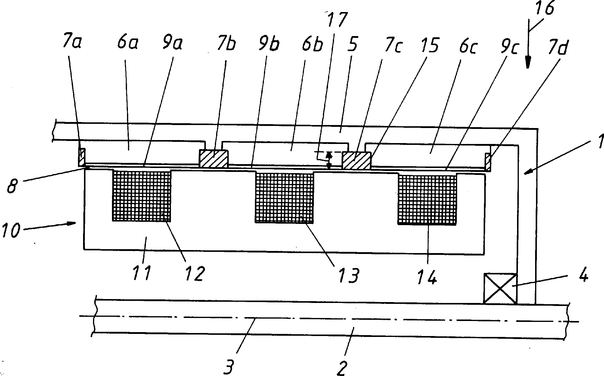
In
Erfindungsgemäß sind nun
am Innenumfang des Rotormantels
Jeder
Rückschlußkern
Wichtig
ist nun, daß jeder
Rückschlußkern
An
der Unterseite des jeweiligen Rückschlußkerns
Bevorzugt
ist die gesamte Anordnung eingegossen, es werden also die Rückschlußkerne
Anstatt
des Eingießens
kann es auch vorgesehen sein, daß die Trägerringe
In
an sich bekannter Weise ist zwischen dem Stator
Der
Stator besteht in dem gezeigten Ausführungsbeispiel aus einem Statorkern
Die
Wicklungen
Wichtig
ist bei dem Ausführungsbeispiel nach
den
Die
Höhe
In
den
In
den Rückschlußkernen
Auch
hier gilt dasselbe wie bezüglich
der Höhe
Die
Permanentmagneten
Der
Stator ist hierbei auf einer Reihe von axial hintereinander angeordneten,
U-förmigen Statorkernen
Die
Die
Dort
ist der Stator
Dort
ist wesentlich, daß der
Trägerring
Seitlich
außen,
in Gegenüberstellung
zu den U-förmigen
Schenkeln des Statorkerns
Diese
Situation ist nochmals in
In
Dort
ist erkennbar, daß der
Permanentmagnet
Die
Bei
diesem Ausführungsbeispiel
ist wesentlich, daß die
Permanentmagnete
Dieses
Beispiel soll nur zeigen, daß auch
bei einer derartigen Rotorkonstruktion erfindungsgemäß vorgesehen
ist, daß Trägerringe
Hierbei
sind in der Nähe
der Stirnseiten der Rückschlußkerne
Auch
hier gelten bezüglich
der Nut
Wesentlich bei allen Ausführungsformen ist, daß also ein in Umfangsrichtung geschlossenes Tragelement in Form eines Trägerrings vorhanden ist, welches nun in der Lage ist, die verteilt am Umfang angeordneten, axial sich erstreckenden Rückschlußkerne zu tragen und gegen radial einwärts gerichtete Kräfte abzustützen.Essential in all embodiments is that so a circumferentially closed support member in the form of a carrier ring is present, which is now able to distributed around the circumference, axially extending return cores too wear and against radially inward directed forces support.
Damit ist es erstmals möglich, stückweise vorhandene Rückschlußkerne zu verwenden, welche gegenüber einer Konstruktion mit ringförmigen Rückschlussblechen eine wesentliche Minimierung der vorhandenen Streupfade ergeben.In order to is it possible for the first time Piecewise available Return cores too use that opposite a construction with annular Return plates result in a substantial minimization of the existing scattering paths.
- 22
- Rotorrotor
- 33
- Wellewave
- 44
- Drehachseaxis of rotation
- 55
- Lagercamp
- 66
- Rotormantelrotor casing
- 77
- Rückschlußkern (Rotor a, b, c)Inference core (rotor a, b, c)
- 88th
- Trägerring a, b, c, dsupport ring a, b, c, d
- 99
- Luftspaltair gap
- 1010
- Permanentmagnet a, b, cpermanent magnet a, b, c
- 1111
- Statorstator
- 1212
- Statorkernstator core
- 1313
- Wicklungwinding
- 1414
- Wicklungwinding
- 1515
- Wicklungwinding
- 1616
- Ausnehmungrecess
- 1717
- Pfeilrichtungarrow
- 1818
- Höhe der Ausnehmung 15Height of the recess 15
- 1919
- Statorkern a, b, cstator core a, b, c
- 2020
- Trägering a, bCarrier a, b
- 2121
- RückschlußkernYoke core
- 2222
- Permanentmagnet a – fpermanent magnet a - f
- 2323
- Ausnehmungrecess
- 2424
- Nutgroove
- 2525
- Trägerringsupport ring
- 2626
- RückschlußkernYoke core
- 2727
- Nutgroove
- 2828
- Permanentmagnet a, bpermanent magnet a, b
- 2929
-
Rückschlußkern
28a , bYoke core28a , b - 3030
- Abstanddistance
- 3131
- Permanentmagnetpermanent magnet
- 3232
- Nutgroove
Claims (16)
Priority Applications (2)
| Application Number | Priority Date | Filing Date | Title |
|---|---|---|---|
| DE10037787A DE10037787B4 (en) | 2000-08-03 | 2000-08-03 | Permanent magnet synchronous machine |
| CH01403/01A CH695717A5 (en) | 2000-08-03 | 2001-07-27 | Permanent magnet synchronous machine. |
Applications Claiming Priority (1)
| Application Number | Priority Date | Filing Date | Title |
|---|---|---|---|
| DE10037787A DE10037787B4 (en) | 2000-08-03 | 2000-08-03 | Permanent magnet synchronous machine |
Publications (2)
| Publication Number | Publication Date |
|---|---|
| DE10037787A1 DE10037787A1 (en) | 2002-03-14 |
| DE10037787B4 true DE10037787B4 (en) | 2005-04-14 |
Family
ID=7651153
Family Applications (1)
| Application Number | Title | Priority Date | Filing Date |
|---|---|---|---|
| DE10037787A Expired - Fee Related DE10037787B4 (en) | 2000-08-03 | 2000-08-03 | Permanent magnet synchronous machine |
Country Status (2)
| Country | Link |
|---|---|
| CH (1) | CH695717A5 (en) |
| DE (1) | DE10037787B4 (en) |
Families Citing this family (6)
| Publication number | Priority date | Publication date | Assignee | Title |
|---|---|---|---|---|
| USRE46449E1 (en) | 2007-07-09 | 2017-06-20 | Clearwater Holdings, Ltd. | Electromagnetic machine with independent removable coils, modular parts and self sustained passive magnetic bearing |
| US7830057B2 (en) | 2008-08-29 | 2010-11-09 | Hamilton Sundstrand Corporation | Transverse flux machine |
| WO2010036221A1 (en) | 2008-09-26 | 2010-04-01 | Clearwater Holdings, Ltd. | Permanent magnet operating machine |
| US10505412B2 (en) | 2013-01-24 | 2019-12-10 | Clearwater Holdings, Ltd. | Flux machine |
| CN111357069B (en) | 2017-09-08 | 2022-08-09 | 清水控股有限公司 | System and method for enhancing electrical storage |
| TWI881525B (en) | 2017-10-29 | 2025-04-21 | 美商清水控股股份有限公司 | Methods of servicing and operating an electromagnetic machine having a plurality of coil modules |
Citations (5)
| Publication number | Priority date | Publication date | Assignee | Title |
|---|---|---|---|---|
| DE4400614A1 (en) * | 1994-01-12 | 1994-06-01 | Voith Gmbh J M | Transversal flow machine rotor - has deforming zones and recesses arranged to compensate voltages arising from properties of adhesive material used |
| DE4325740C1 (en) * | 1993-07-31 | 1995-04-06 | Weh Herbert | Transversal flux machine with improved magnetic circuits |
| EP0790695A1 (en) * | 1996-02-14 | 1997-08-20 | KOEHLER, Gérard | Hybrid dynamo-electric variable reluctance machine and manufacturing and calculation method |
| EP0998010A1 (en) * | 1998-10-30 | 2000-05-03 | DaimlerChrysler AG | Transversal flux machine |
| EP1005136A1 (en) * | 1998-11-27 | 2000-05-31 | DaimlerChrysler AG | One-phase or multiphase transversal flux machine |
-
2000
- 2000-08-03 DE DE10037787A patent/DE10037787B4/en not_active Expired - Fee Related
-
2001
- 2001-07-27 CH CH01403/01A patent/CH695717A5/en not_active IP Right Cessation
Patent Citations (5)
| Publication number | Priority date | Publication date | Assignee | Title |
|---|---|---|---|---|
| DE4325740C1 (en) * | 1993-07-31 | 1995-04-06 | Weh Herbert | Transversal flux machine with improved magnetic circuits |
| DE4400614A1 (en) * | 1994-01-12 | 1994-06-01 | Voith Gmbh J M | Transversal flow machine rotor - has deforming zones and recesses arranged to compensate voltages arising from properties of adhesive material used |
| EP0790695A1 (en) * | 1996-02-14 | 1997-08-20 | KOEHLER, Gérard | Hybrid dynamo-electric variable reluctance machine and manufacturing and calculation method |
| EP0998010A1 (en) * | 1998-10-30 | 2000-05-03 | DaimlerChrysler AG | Transversal flux machine |
| EP1005136A1 (en) * | 1998-11-27 | 2000-05-31 | DaimlerChrysler AG | One-phase or multiphase transversal flux machine |
Also Published As
| Publication number | Publication date |
|---|---|
| DE10037787A1 (en) | 2002-03-14 |
| CH695717A5 (en) | 2006-07-31 |
Similar Documents
| Publication | Publication Date | Title |
|---|---|---|
| DE3427677C2 (en) | ||
| DE19507233C2 (en) | Transverse flux machine with permanent excitation and multi-strand armature winding | |
| DE69309444T2 (en) | BRUSHLESS DC MOTOR / GENERATOR | |
| DE60212406T2 (en) | Runners with embedded permanent magnets | |
| EP2766976B1 (en) | Optimized spider rotor internal geometry | |
| WO2003081748A1 (en) | Inner rotor motor | |
| DE102009054069A1 (en) | Three-phase dynamo-electric permanent-magnet synchronous machine | |
| DE60201937T2 (en) | Electric machine with external rotor | |
| DE102006022836A1 (en) | Stator arrangement and rotor arrangement for a transverse flux machine | |
| EP0762619A2 (en) | Method and device for reducing cogging in an electric motor | |
| DE102008032844A1 (en) | Permanent magnetic rotor | |
| DE102010041015A1 (en) | Machine component for an electrical machine | |
| DE102009060438A1 (en) | Rotor with short-circuit cage | |
| DE102010054847A1 (en) | Brushless electric motor or generator in shell construction | |
| DE102004017507A1 (en) | Rotor arrangement for an electric machine | |
| EP1657801A2 (en) | Rotor for an electrical machine and manufacturing method for a rotor | |
| DE2953033C2 (en) | Rotor of an electrical machine with pronounced poles | |
| DE102013109448B4 (en) | Electromechanical converter | |
| DE102013200476A1 (en) | Permanent magnet-excited two-pole synchronous machine e.g. wind force generator, for use as inner rotor machine in wind-power plant, has pockets comprising magnets that exhibits magnetization direction to form magnetic poles of rotor | |
| DE102016212022A1 (en) | rotor | |
| EP2973944B1 (en) | Single segment rotor with retaining rings | |
| WO2003026106A1 (en) | Electronically-commutated electric motor comprising coils with parallel axes | |
| DE10037787B4 (en) | Permanent magnet synchronous machine | |
| DE102020101639A1 (en) | Rotor and axial flux machine | |
| DE102009010162A1 (en) | Multiaxial electrical machine for corrugated array, has multiple axially parallel rotors and common stator, where filtered magnetic fluxes of two windings are interacted with different rotors |
Legal Events
| Date | Code | Title | Description |
|---|---|---|---|
| OM8 | Search report available as to paragraph 43 lit. 1 sentence 1 patent law | ||
| OP8 | Request for examination as to paragraph 44 patent law | ||
| 8364 | No opposition during term of opposition | ||
| 8339 | Ceased/non-payment of the annual fee |