EP0728947A1 - Scroll vacuum pump - Google Patents
Scroll vacuum pump Download PDFInfo
- Publication number
- EP0728947A1 EP0728947A1 EP96400385A EP96400385A EP0728947A1 EP 0728947 A1 EP0728947 A1 EP 0728947A1 EP 96400385 A EP96400385 A EP 96400385A EP 96400385 A EP96400385 A EP 96400385A EP 0728947 A1 EP0728947 A1 EP 0728947A1
- Authority
- EP
- European Patent Office
- Prior art keywords
- disc
- pump
- spiral
- projection
- fixed
- Prior art date
- Legal status (The legal status is an assumption and is not a legal conclusion. Google has not performed a legal analysis and makes no representation as to the accuracy of the status listed.)
- Granted
Links
- 229910052751 metal Inorganic materials 0.000 claims abstract description 20
- 239000002184 metal Substances 0.000 claims abstract description 20
- 230000002093 peripheral effect Effects 0.000 claims description 11
- 239000000463 material Substances 0.000 claims description 6
- 230000000694 effects Effects 0.000 claims description 5
- 230000000295 complement effect Effects 0.000 claims description 3
- 238000005096 rolling process Methods 0.000 claims description 3
- 239000012530 fluid Substances 0.000 description 3
- 239000011347 resin Substances 0.000 description 2
- 229920005989 resin Polymers 0.000 description 2
- 229910000838 Al alloy Inorganic materials 0.000 description 1
- 241001125831 Istiophoridae Species 0.000 description 1
- 238000005452 bending Methods 0.000 description 1
- 238000004891 communication Methods 0.000 description 1
- 230000006835 compression Effects 0.000 description 1
- 238000007906 compression Methods 0.000 description 1
- 238000001816 cooling Methods 0.000 description 1
- 238000006073 displacement reaction Methods 0.000 description 1
- 239000004519 grease Substances 0.000 description 1
- 238000009413 insulation Methods 0.000 description 1
- 239000000314 lubricant Substances 0.000 description 1
- 238000003754 machining Methods 0.000 description 1
- CWQXQMHSOZUFJS-UHFFFAOYSA-N molybdenum disulfide Chemical compound S=[Mo]=S CWQXQMHSOZUFJS-UHFFFAOYSA-N 0.000 description 1
- 229910052982 molybdenum disulfide Inorganic materials 0.000 description 1
- 238000000465 moulding Methods 0.000 description 1
- 239000003921 oil Substances 0.000 description 1
- -1 polyethylene terephthalate Polymers 0.000 description 1
- 229920000139 polyethylene terephthalate Polymers 0.000 description 1
- 239000005020 polyethylene terephthalate Substances 0.000 description 1
- 229920001296 polysiloxane Polymers 0.000 description 1
- 230000000750 progressive effect Effects 0.000 description 1
- 238000005086 pumping Methods 0.000 description 1
- 239000010935 stainless steel Substances 0.000 description 1
- 229910001220 stainless steel Inorganic materials 0.000 description 1
- 230000001360 synchronised effect Effects 0.000 description 1
- 238000009423 ventilation Methods 0.000 description 1
Images
Classifications
-
- F—MECHANICAL ENGINEERING; LIGHTING; HEATING; WEAPONS; BLASTING
- F04—POSITIVE - DISPLACEMENT MACHINES FOR LIQUIDS; PUMPS FOR LIQUIDS OR ELASTIC FLUIDS
- F04C—ROTARY-PISTON, OR OSCILLATING-PISTON, POSITIVE-DISPLACEMENT MACHINES FOR LIQUIDS; ROTARY-PISTON, OR OSCILLATING-PISTON, POSITIVE-DISPLACEMENT PUMPS
- F04C29/00—Component parts, details or accessories of pumps or pumping installations, not provided for in groups F04C18/00 - F04C28/00
- F04C29/0042—Driving elements, brakes, couplings, transmissions specially adapted for pumps
- F04C29/005—Means for transmitting movement from the prime mover to driven parts of the pump, e.g. clutches, couplings, transmissions
- F04C29/0057—Means for transmitting movement from the prime mover to driven parts of the pump, e.g. clutches, couplings, transmissions for eccentric movement
-
- F—MECHANICAL ENGINEERING; LIGHTING; HEATING; WEAPONS; BLASTING
- F04—POSITIVE - DISPLACEMENT MACHINES FOR LIQUIDS; PUMPS FOR LIQUIDS OR ELASTIC FLUIDS
- F04C—ROTARY-PISTON, OR OSCILLATING-PISTON, POSITIVE-DISPLACEMENT MACHINES FOR LIQUIDS; ROTARY-PISTON, OR OSCILLATING-PISTON, POSITIVE-DISPLACEMENT PUMPS
- F04C18/00—Rotary-piston pumps specially adapted for elastic fluids
- F04C18/02—Rotary-piston pumps specially adapted for elastic fluids of arcuate-engagement type, i.e. with circular translatory movement of co-operating members, each member having the same number of teeth or tooth-equivalents
-
- F—MECHANICAL ENGINEERING; LIGHTING; HEATING; WEAPONS; BLASTING
- F01—MACHINES OR ENGINES IN GENERAL; ENGINE PLANTS IN GENERAL; STEAM ENGINES
- F01C—ROTARY-PISTON OR OSCILLATING-PISTON MACHINES OR ENGINES
- F01C17/00—Arrangements for drive of co-operating members, e.g. for rotary piston and casing
-
- F—MECHANICAL ENGINEERING; LIGHTING; HEATING; WEAPONS; BLASTING
- F01—MACHINES OR ENGINES IN GENERAL; ENGINE PLANTS IN GENERAL; STEAM ENGINES
- F01C—ROTARY-PISTON OR OSCILLATING-PISTON MACHINES OR ENGINES
- F01C21/00—Component parts, details or accessories not provided for in groups F01C1/00 - F01C20/00
- F01C21/10—Outer members for co-operation with rotary pistons; Casings
- F01C21/102—Adjustment of the interstices between moving and fixed parts of the machine by means other than fluid pressure
-
- F—MECHANICAL ENGINEERING; LIGHTING; HEATING; WEAPONS; BLASTING
- F04—POSITIVE - DISPLACEMENT MACHINES FOR LIQUIDS; PUMPS FOR LIQUIDS OR ELASTIC FLUIDS
- F04C—ROTARY-PISTON, OR OSCILLATING-PISTON, POSITIVE-DISPLACEMENT MACHINES FOR LIQUIDS; ROTARY-PISTON, OR OSCILLATING-PISTON, POSITIVE-DISPLACEMENT PUMPS
- F04C18/00—Rotary-piston pumps specially adapted for elastic fluids
- F04C18/02—Rotary-piston pumps specially adapted for elastic fluids of arcuate-engagement type, i.e. with circular translatory movement of co-operating members, each member having the same number of teeth or tooth-equivalents
- F04C18/0207—Rotary-piston pumps specially adapted for elastic fluids of arcuate-engagement type, i.e. with circular translatory movement of co-operating members, each member having the same number of teeth or tooth-equivalents both members having co-operating elements in spiral form
- F04C18/0215—Rotary-piston pumps specially adapted for elastic fluids of arcuate-engagement type, i.e. with circular translatory movement of co-operating members, each member having the same number of teeth or tooth-equivalents both members having co-operating elements in spiral form where only one member is moving
- F04C18/0223—Rotary-piston pumps specially adapted for elastic fluids of arcuate-engagement type, i.e. with circular translatory movement of co-operating members, each member having the same number of teeth or tooth-equivalents both members having co-operating elements in spiral form where only one member is moving with symmetrical double wraps
Definitions
- the present invention relates to a vacuum pump with circular translation cycle.
- a vacuum pump with circular translation cycle comprising a fixed body having a fixed disc which has on at least one of its sides a spiral-shaped projection, a movable disc opposite the fixed disc and also having at least a spiral-shaped projection interposed with the spiral-shaped projection of the fixed disc and of the same angular amplitude, a mechanism by which the movable disc is connected to and supported by said body, to control a circular translational movement of the movable disc by relation to said body during operation of the pump, motor means for driving the movable disc via a pump shaft and causing it to effect said movement of circular translation, said pump also comprising a device for limiting the movement of circular translation guiding the mobile disc in its circular translational movement, avoiding any twisting.
- a pump of this type is for example described in FR-A-2 141 402. If such a pump according to this document gives excellent results, it nevertheless has the drawback of comprising numerous parts and of being bulky, in particular radially. due in particular to the fact that said mechanism consists of three cranks coupled in a synchronized manner with each other and arranged at the periphery of the pump, these cranks ensuring by themselves the limitation of the circular translation movement.
- the object of the present invention is to produce a pump of the above type which does not have these drawbacks.
- a vacuum pump with circular translation cycle comprising a fixed body having at least one fixed disc which has on one of its sides a projection in the form of a spiral, a movable disc opposite to the fixed disc and also having at least one spiral-shaped projection interposed with the spiral-shaped projection of the fixed disc and of the same angular amplitude, a mechanism by which the movable disc is connected to and supported by said body to control movement of circular translation of the movable disc with respect to said body during the operation of the pump, motor means for driving the mobile disc via a pump shaft and causing it to effect said circular translational movement, said pump also comprising a circular translation movement limiting device, said mechanism comprising at least one bearing carried by the pump shaft, is characterized in that said pump shaft is in a central position relative to the fixed body, said mechanism also comprises a crank shaft which is adapted to move in a circular translational movement and which is coupled, by one of its ends, to the movable disc which it drives in its movement, while its other end, close to
- Such a bellows is capable of ensuring the limitation of travel, or anti-twist, function when the pump is dimensioned to generate volumes at most equal to 25 m 3 / hour, and this without problem, especially without fatigue; it will be noted, moreover, that such a bellows at the same time ensures total insulation of the pump enclosure, where the vacuum is produced, with respect to the exterior and to the rest of the pump, which increases the number of possible applications of such a pump.
- Such a pump is thus part of the so-called dry pumps whose active parts are isolated from the outside and free from any lubricant, oil or grease. We will easily understand that such a pump is very simple, compact and, consequently, low cost.
- the pump comprises a movable disc consisting of two movable plates, the spiral projections of which are on opposite faces of the movable plates, the movable disc being placed between an annular fixed disc and a flange, the opposite faces of which carry the spiral projections. fixed.
- the flange has a projection in the form of a peripheral spiral extending towards the axis of the pump according to a projection in the form of a central spiral, the axial height of which is less than that of the peripheral projection, the two peripheral and central projections having their free ends in the same transverse plane, one of the mobile plates, opposite the flange, being provided, on the one hand, with a projection in the form of a spiral interposed with the peripheral projection of the flange and of the same angular amplitude and, d 'on the other hand, a spiral-shaped projection interspersed with the central projection of the flange and of the same angular amplitude.
- the two plates of the movable disc are connected by an annular ring with a U-shaped cross section, the walls of which have a thickness allowing the two plates to move axially relative to one another; a spring placed between the two plates urges them axially away from one another.
- the plates, their projections and the annular crown are in one piece of a material allowing contact between the movable disc, on the one hand, and the fixed disc and flange, on the other hand, provided in metal, this contact being at minimum friction; preferably, the spiral projections of the fixed disc and the spiral projections of the movable disc cooperate in friction during operation of the pump.
- crankshaft has a central part of generally frustoconical shape, the end of which is located on the side of the small base. carries a cylindrical sleeve provided on its outer surface with longitudinal grooves cooperating with complementary longitudinal grooves formed on the inner surface of a skirt carried by the movable plate opposite the flange.
- the skirt is also made in one piece with the movable disc.
- the pump shaft is a hollow shaft having, on the one hand, an external cylindrical bearing surface by which it is supported by the frame by means of rolling means and, on the other hand, a cylindrical bore receiving the bearing with interposition of a bearing, the external cylindrical bearing being offset axially with respect to the cylindrical bore whose diameter is greater than the diameter of the external cylindrical bearing.
- the metal bellows has two corrugated zones placed axially on either side of a cylindrical central zone.
- a circular translation cycle vacuum pump comprises a fixed body 10 formed, according to the example shown, by the assembly of four elements 11 to 14, namely a sleeve 11, an intermediate plate 12, a fixed annular disc 13 and a flange 14, arranged successively axially in the order in which they have just been cited; these elements are assembled by screws such as the screws 15 distributed circumferentially; annular seals 16 and 17 are interposed between the intermediate plate 12 and the annular disc 13, on the one hand, and between this same annular disc 13 and the flange 14, on the other hand, respectively.
- the annular fixed disc 13 has on the side which faces the flange 14 a spiral-shaped projection 23; the flange 14 has on the side which faces the annular disc 13 also a peripheral spiral-shaped projection 24 extending towards the axis of the pump according to a central spiral-shaped projection 25 whose axial height is less than that of the peripheral projection 24, the two peripheral 24 and central 25 projections having their free ends in the same transverse plane 18.
- a movable disc 30 is placed between the annular fixed disc 13 and the flange 14 also fixed;
- the movable disc 30 comprises a first plate 31 opposite the fixed disc 13 and provided with a spiral-shaped projection 33 interposed with the projection 23 of the fixed disc 13 and of the same angular amplitude;
- the movable disc 30 also includes a second plate 32 opposite the flange 14 and provided, on the one hand, with a spiral-shaped projection 34 interposed with the projection 24 of the flange 14 and of the same angular amplitude and, on the other hand , a spiral-shaped projection 35 interposed with the projection 25 of the flange 14 and of the same angular amplitude.
- the two plates 31, 32 are connected by an annular ring 36 with a U-shaped section open towards the outside relative to the axis of the pump; the thickness of the walls of U-shaped section of the annular ring 36 is relatively small so that the plates 31, 32 have a possibility of axial displacement relative to each other; a helical spring 37 placed between the plates 31, 32 urges them axially away from one another.
- the plates 31, 32 and their spiral projections 33, 34, 35 as well as the annular ring 36 are produced, by molding and / or machining, in one piece from a material allowing contact between the movable disc 30, on the one hand, and the disc 13 and the fixed flange 14, on the other hand, provided in metal, such than stainless steel or an aluminum alloy, this contact being at minimum friction;
- a material is, for example, that which is marketed under the trade name VESCONITE by the company MARLIN INTERNATIONAL; this material which, as is known, is based on polyethylene terephthalate, contains a silicone fluid and molybdenum disulfide minimizing the friction on a metal part; an equivalent material other than this can of course be used to make the movable disc 30; it is likewise possible to produce all the parts in metallic contact and to coat at least one of them, the moving part for example, with a small thickness, like a few microns, of a suitable resin such as the resin fluorinated product sold under the trade name F
- a mechanism for connecting the movable disc 30 to the fixed body 10 and supporting it; this mechanism comprises a crank shaft 40 having a central part 45 of generally frustoconical shape, the end of which located on the side of the small base carries a cylindrical sleeve 41 provided on its outer surface with longitudinal grooves 42 cooperating with complementary longitudinal grooves 38 formed at the inner surface of a skirt 39 carried by the second plate 32; the skirt 39 is also made in one piece with the movable disc 30; at its other end, the frustoconical central part 45 of the crank shaft 40 has a flange 43, of larger diameter than that of the large base of the central part 45; the collar 43 extends along a frustoconical end 44 of angle inverted with respect to that of the central part 45; this frustoconical end 44 is secured by a screw 46 to a bearing 47 supporting a bearing 48 internally supported also externally by being engaged in the cylindrical bore 51 of a central drive shaft of the pump here a hollow shaft 50 centered on axis 55 of
- the external cylindrical surface 52 is axially offset from to the cylindrical bore 51, the diameter of which is moreover greater than the diameter of the external cylindrical seat 52; thanks to this arrangement, added to that according to which the crank formed by the bearing 47 is placed axially away from the fixed 13 and movable 30 discs, the pump advantageously has a small diametrical size.
- the hollow shaft 50 is secured to a drive flange 26 having fingers 27 inserted circumferentially between fingers 28 of a nut 29 secured, by means of a key 22, to the motor shaft 21 of a motor 20 partially shown in figure 1.
- the central part 45 of the crank shaft 40 is, according to the invention, surrounded by a metal bellows 60;
- the metal bellows 60 advantageously has two corrugated zones 60A, 60C placed axially on either side of a cylindrical central zone 60B; it is fixed by one of its ends to the flange 43 of the crank shaft 40; the other end of the bellows 60 is fixed, at the end of a bell 53 secured to the intermediate plate 12 of the frame 10, as close as possible to the skirt 39 of the second plate 32 of the movable disc 30, so that the bellows 60 is very long: thanks to this arrangement, the bending angle of the bellows 60 in operation is small, thus limiting the fatigue of the corrugated zones 60A, 60C of the bellows 60; the metal bellows 60 ensures good guidance of the movable disc 30 in its circular translational movement by preventing the shaft 40 from turning on itself, that is to say any undesirable torsional effect.
- the motor shaft 21 of the motor 20 is centered on the axis 55 of the pump; the axis 65 of the bearing 47, which is also the axis of the crank shaft 40, is eccentric relative to the axis 55 of the pump.
- a ventilation unit 54 cools the transverse external face of the flange 14 provided relatively massive to absorb the calories produced by pumping and transmit them to the cooling air.
- the last stage of the pump constituted by the projections 25 and 35 of small dimensions allows a pressure of the fluid at the exhaust practically equal to atmospheric pressure.
Landscapes
- Engineering & Computer Science (AREA)
- Mechanical Engineering (AREA)
- General Engineering & Computer Science (AREA)
- Physics & Mathematics (AREA)
- Fluid Mechanics (AREA)
- Reciprocating Pumps (AREA)
- Rotary Pumps (AREA)
- Compressors, Vaccum Pumps And Other Relevant Systems (AREA)
- Applications Or Details Of Rotary Compressors (AREA)
- Non-Positive Displacement Air Blowers (AREA)
- Structures Of Non-Positive Displacement Pumps (AREA)
- Transmission Devices (AREA)
- Compressor (AREA)
Abstract
Description
La présente invention concerne une pompe à vide à cycle de translation circulaire.The present invention relates to a vacuum pump with circular translation cycle.
Plus précisément, elle concerne une pompe à vide à cycle de translation circulaire comportant un corps fixe ayant un disque fixe qui présente sur au moins un de ses côtés une saillie en forme de spirale, un disque mobile opposé au disque fixe et ayant également au moins une saillie en forme de spirale intercalée avec la saillie en forme de spirale du disque fixe et de même amplitude angulaire, un mécanisme par lequel le disque mobile est relié audit corps et supporté par lui, pour commander un mouvement de translation circulaire du disque mobile par rapport audit corps pendant le fonctionnement de la pompe, des moyens moteurs pour entraîner le disque mobile par l'intermédiaire d'un arbre de pompe et lui faire effectuer ledit mouvement de translation circulaire, ladite pompe comportant également un dispositif limiteur de débattement de translation circulaire guidant le disque mobile dans son mouvement de translation circulaire en évitant toute torsion.More specifically, it relates to a vacuum pump with circular translation cycle comprising a fixed body having a fixed disc which has on at least one of its sides a spiral-shaped projection, a movable disc opposite the fixed disc and also having at least a spiral-shaped projection interposed with the spiral-shaped projection of the fixed disc and of the same angular amplitude, a mechanism by which the movable disc is connected to and supported by said body, to control a circular translational movement of the movable disc by relation to said body during operation of the pump, motor means for driving the movable disc via a pump shaft and causing it to effect said movement of circular translation, said pump also comprising a device for limiting the movement of circular translation guiding the mobile disc in its circular translational movement, avoiding any twisting.
Une pompe de ce type est par exemple décrite dans FR-A-2 141 402. Si une telle pompe selon ce document donne d'excellents résultats, elle présente toutefois l'inconvénient de comporter de nombreuses pièces et d'être encombrante notamment radialement compte tenu en particulier du fait que ledit mécanisme est constitué de trois manivelles accouplées de manière synchronisée les unes avec les autres et disposées à la périphérie de la pompe, ces manivelles assurant par elle-même la limitation du débattement de translation circulaire.A pump of this type is for example described in FR-A-2 141 402. If such a pump according to this document gives excellent results, it nevertheless has the drawback of comprising numerous parts and of being bulky, in particular radially. due in particular to the fact that said mechanism consists of three cranks coupled in a synchronized manner with each other and arranged at the periphery of the pump, these cranks ensuring by themselves the limitation of the circular translation movement.
La présente invention a pour but de réaliser une pompe du type ci-dessus ne présentant pas ces inconvénients.The object of the present invention is to produce a pump of the above type which does not have these drawbacks.
Ainsi, selon l'invention, une pompe à vide à cycle de translation circulaire comportant un corps fixe ayant au moins un disque fixe qui présente sur un de ses côtés une saillie en forme de spirale, un disque mobile opposé au disque fixe et ayant également au moins une saillie en forme de spirale intercalée avec la saillie en forme de spirale du disque fixe et de même amplitude angulaire, un mécanisme par lequel le disque mobile est relié audit corps et supporté par lui, pour commander un mouvement de translation circulaire du disque mobile par rapport audit corps pendant le fonctionnement de la pompe, des moyens moteurs pour entraîner le disque mobile par l'intermédiaire d'un arbre de pompe et lui faire effectuer ledit mouvement de translation circulaire, ladite pompe comportant également un dispositif limiteur de débattement de translation circulaire, ledit mécanisme comprenant au moins un palier porté par l'arbre de pompe, est caractérisée par le fait que ledit arbre de pompe est en position centrale par rapport au corps fixe, ledit mécanisme comprend également un arbre manivelle qui est adapté à se déplacer suivant un mouvement de translation circulaire et qui est attelé, par une de ses extrémités, au disque mobile qu'il entraîne dans son mouvement, tandis que son autre extrémité, proche des moyens moteurs, est supportée par ledit palier, et en ce que le dispositif limiteur de débattement de translation circulaire est un soufflet métallique, une extrémité du soufflet métallique étant solidaire du corps fixe et l'autre extrémité du soufflet métallique étant solidaire de l'arbre manivelle, le soufflet métallique entourant l'arbre manivelle.Thus, according to the invention, a vacuum pump with circular translation cycle comprising a fixed body having at least one fixed disc which has on one of its sides a projection in the form of a spiral, a movable disc opposite to the fixed disc and also having at least one spiral-shaped projection interposed with the spiral-shaped projection of the fixed disc and of the same angular amplitude, a mechanism by which the movable disc is connected to and supported by said body to control movement of circular translation of the movable disc with respect to said body during the operation of the pump, motor means for driving the mobile disc via a pump shaft and causing it to effect said circular translational movement, said pump also comprising a circular translation movement limiting device, said mechanism comprising at least one bearing carried by the pump shaft, is characterized in that said pump shaft is in a central position relative to the fixed body, said mechanism also comprises a crank shaft which is adapted to move in a circular translational movement and which is coupled, by one of its ends, to the movable disc which it drives in its movement, while its other end, close to the motor means, is supported by said bearing, and in that the device for limiting the movement of circular translation is a metal bellows, one end the metal bellows being secured to the fixed body and the other end of the metal bellows being secured to the crank shaft, the metal bellows surrounding the crank shaft.
L'expérience a en effet montré qu'un tel soufflet est capable d'assurer la fonction limitation de débattement, ou anti-torsion, lorsque la pompe est dimensionnée pour engendrer des volumes au plus égaux à 25 m3 /heure, et ce sans problème, notamment sans fatigue ; on notera, par ailleurs, qu'un tel soufflet assure en même temps l'isolation totale de l'enceinte de la pompe, où se réalise le vide, par rapport à l'extérieur et au reste de la pompe, ce qui augmente le nombre d'applications possibles d'une telle pompe. Une telle pompe fait ainsi partie des pompes dites sèches dont les parties actives sont isolées de l'extérieur et exemptes de tout lubrifiant, huile ou graisse. On comprendra aisément qu'une telle pompe est d'une grande simplicité, d'un faible encombrement et, par voie de conséquence, d'un faible prix de revient.Experience has indeed shown that such a bellows is capable of ensuring the limitation of travel, or anti-twist, function when the pump is dimensioned to generate volumes at most equal to 25 m 3 / hour, and this without problem, especially without fatigue; it will be noted, moreover, that such a bellows at the same time ensures total insulation of the pump enclosure, where the vacuum is produced, with respect to the exterior and to the rest of the pump, which increases the number of possible applications of such a pump. Such a pump is thus part of the so-called dry pumps whose active parts are isolated from the outside and free from any lubricant, oil or grease. We will easily understand that such a pump is very simple, compact and, consequently, low cost.
Avantageusement, la pompe comprend un disque mobile constitué de deux plateaux mobiles dont les saillies en spirale sont sur des faces opposées des plateaux mobiles, le disque mobile étant placé entre un disque fixe annulaire et un flasque dont les faces en regard portent les saillies en spirale fixes.Advantageously, the pump comprises a movable disc consisting of two movable plates, the spiral projections of which are on opposite faces of the movable plates, the movable disc being placed between an annular fixed disc and a flange, the opposite faces of which carry the spiral projections. fixed.
Avantageusement, le flasque présente une saillie en forme de spirale périphérique se prolongeant vers l'axe de la pompe selon une saillie en forme de spirale centrale dont la hauteur axiale est moindre que celle de la saillie périphérique, les deux saillies périphérique et centrale ayant leurs extrémités libres dans un même plan transversal, l'un des plateaux mobiles, opposé au flasque, étant muni, d'une part, d'une saillie en forme de spirale intercalée avec la saillie périphérique du flasque et de même amplitude angulaire et, d'autre part, d'une saillie en forme de spirale intercalée avec la saillie centrale du flasque et de même amplitude angulaire.Advantageously, the flange has a projection in the form of a peripheral spiral extending towards the axis of the pump according to a projection in the form of a central spiral, the axial height of which is less than that of the peripheral projection, the two peripheral and central projections having their free ends in the same transverse plane, one of the mobile plates, opposite the flange, being provided, on the one hand, with a projection in the form of a spiral interposed with the peripheral projection of the flange and of the same angular amplitude and, d 'on the other hand, a spiral-shaped projection interspersed with the central projection of the flange and of the same angular amplitude.
De préférence, les deux plateaux du disque mobile sont reliés par une couronne annulaire à section en forme de U dont les parois ont une épaisseur permettant aux deux plateaux de se déplacer axialement l'un par rapport à l'autre ; un ressort placé entre les deux plateaux les sollicite en éloignement axial l'un par rapport à l'autre.Preferably, the two plates of the movable disc are connected by an annular ring with a U-shaped cross section, the walls of which have a thickness allowing the two plates to move axially relative to one another; a spring placed between the two plates urges them axially away from one another.
Avantageusement, les plateaux, leurs saillies et la couronne annulaire sont d'une seule pièce en une matière autorisant un contact entre le disque mobile, d'une part, et le disque et le flasque fixes, d'autre part, prévus en métal, ce contact étant à frottement minimum ; de préférence, les saillies en spirale du disque fixe et les saillies en spirale du disque mobile coopèrent en frottement lors du fonctionnement de la pompe.Advantageously, the plates, their projections and the annular crown are in one piece of a material allowing contact between the movable disc, on the one hand, and the fixed disc and flange, on the other hand, provided in metal, this contact being at minimum friction; preferably, the spiral projections of the fixed disc and the spiral projections of the movable disc cooperate in friction during operation of the pump.
Avantageusement, l'arbre manivelle présente une partie centrale de forme générale tronconique dont l'extrémité située du côté de la petite base porte un manchon cylindrique muni à sa surface extérieure de cannelures longitudinales coopérant avec des cannelures complémentaires longitudinales ménagées à la surface intérieure d'une jupe portée par le plateau mobile opposé au flasque.Advantageously, the crankshaft has a central part of generally frustoconical shape, the end of which is located on the side of the small base. carries a cylindrical sleeve provided on its outer surface with longitudinal grooves cooperating with complementary longitudinal grooves formed on the inner surface of a skirt carried by the movable plate opposite the flange.
De préférence, la jupe est également réalisée d'une seule pièce avec le disque mobile.Preferably, the skirt is also made in one piece with the movable disc.
Avantageusement, l'arbre de pompe est un arbre creux présentant, d'une part, une portée cylindrique externe par laquelle il est supporté par le bâti par l'intermédiaire de moyens de roulement et, d'autre part, un alésage cylindrique recevant le palier avec interposition d'un roulement, la portée cylindrique externe étant décalée axialement par rapport à l'alésage cylindrique dont le diamètre est supérieur au diamètre de la portée cylindrique externe.Advantageously, the pump shaft is a hollow shaft having, on the one hand, an external cylindrical bearing surface by which it is supported by the frame by means of rolling means and, on the other hand, a cylindrical bore receiving the bearing with interposition of a bearing, the external cylindrical bearing being offset axially with respect to the cylindrical bore whose diameter is greater than the diameter of the external cylindrical bearing.
De préférence, le soufflet métallique présente deux zones ondulées placées axialement de part et d'autre d'une zone centrale cylindrique.Preferably, the metal bellows has two corrugated zones placed axially on either side of a cylindrical central zone.
Les caractéristiques et avantages de l'invention ressortiront d'ailleurs de la description qui va suivre, à titre d'exemple en référence au dessin annexé sur lequel :
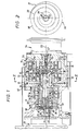
- La figure 1 est une vue en coupe longitudinale partielle d'une pompe selon l'invention ;
- la figure 2 est une vue en bout selon II-II de la figure 1 du double-plateau mobile seul.
- Figure 1 is a partial longitudinal sectional view of a pump according to the invention;
- Figure 2 is an end view along II-II of Figure 1 of the movable double plate alone.
En se reportant aux figures 1 et 2, une pompe à vide à cycle de translation circulaire comprend un corps fixe 10 constitué, selon l'exemple représenté, par l'assemblage de quatre éléments 11 à 14 à savoir un manchon 11, un plateau intermédiaire 12, un disque fixe 13 annulaire et un flasque 14, disposés successivement axialement dans l'ordre dans lequel ils viennent d'être cités ; ces éléments sont assemblés par des vis telles que les vis 15 réparties circonférentiellement ; des joints d'étanchéité annulaires 16 et 17 sont interposés entre le plateau intermédiaire 12 et le disque annulaire 13, d'une part, et entre ce même disque annulaire 13 et le flasque 14, d'autre part, respectivement.Referring to Figures 1 and 2, a circular translation cycle vacuum pump comprises a
Le disque fixe annulaire 13 présente du côté qui fait face au flasque 14 une saillie en forme de spirale 23 ; le flasque 14 présente du côté qui fait face au disque annulaire 13 également une saillie en forme de spirale 24 périphérique se prolongeant vers l'axe de la pompe selon une saillie en forme de spirale 25 centrale dont la hauteur axiale est moindre que celle de la saillie 24 périphérique, les deux saillies périphérique 24 et centrale 25 ayant leurs extrémités libres dans un même plan transversal 18.The annular
Un disque mobile 30 est placé entre le disque fixe annulaire 13 et le flasque 14 également fixe ; le disque mobile 30 comporte un premier plateau 31 opposé au disque fixe 13 et muni d'une saillie en forme de spirale 33 intercalée avec la saillie 23 du disque fixe 13 et de même amplitude angulaire ; le disque mobile 30 comporte également un second plateau 32 opposé au flasque 14 et muni, d'une part, d'une saillie en forme de spirale 34 intercalée avec la saillie 24 du flasque 14 et de même amplitude angulaire et, d'autre part, d'une saillie en forme de spirale 35 intercalée avec la saillie 25 du flasque 14 et de même amplitude angulaire.A
Les deux plateaux 31, 32 sont reliés par une couronne annulaire 36 à section en forme de U ouvert vers l'extérieur par rapport à l'axe de la pompe ; l'épaisseur des parois à section en forme U de la couronne annulaire 36 est relativement faible de sorte que les plateaux 31, 32 ont une possibilité de déplacement axial l'un par rapport à l'autre ; un ressort hélicoïdal 37 placé entre les plateaux 31, 32 les sollicite en éloignement axial l'un par rapport à l'autre.The two
Les plateaux 31, 32 et leurs saillies en spirale 33, 34, 35 ainsi que la couronne annulaire 36 sont réalisés, par moulage et/ou usinage, d'une seule pièce en une matière autorisant un contact entre le disque mobile 30, d'une part, et le disque 13 et le flasque 14 fixes, d'autre part, prévus en métal, tel que l'acier inoxydable ou un alliage d'aluminium, ce contact étant à frottement minimum ; une telle matière est, par exemple, celle qui est commercialisée sous la dénomination commerciale VESCONITE par la Société MARLIN INTERNATIONAL ; cette matière qui, comme on le sait, est à base de polyethylene téréphtalate, contient un fluide silicone et du disulfide de molybdène minimisant le frottement sur une pièce métallique ; une matière équivalente autre que celle-ci peut bien entendu être utilisée pour réaliser le disque mobile 30 ; il est de même possible de réaliser toutes les pièces en contact métalliques et de revêtir au moins l'une d'elles, la pièce mobile par exemple, d'une faible épaisseur, comme quelques microns, d'une résine adaptée telle que la résine fluorée commercialisée sous la dénomination commerciale FLUORIMID 10P par la société FLUOROTECHNIQUE. Grâce à ces dispositions, le rendement de la pompe est élevé eu égard à sa taille.The
Un mécanisme est prévu pour relier le disque mobile 30 au corps fixe 10 et le supporter ; ce mécanisme comprend un arbre manivelle 40 ayant une partie centrale 45 de forme générale tronconique dont l'extrémité située du côté de la petite base porte un manchon 41 cylindrique muni à sa surface extérieure de cannelures longitudinales 42 coopérant avec des cannelures complémentaires longitudinales 38 ménagées à la surface intérieure d'une jupe 39 portée par le second plateau 32 ; la jupe 39 est également réalisée d'une seule pièce avec le disque mobile 30 ; à son autre extrémité, la partie centrale tronconique 45 de l'arbre manivelle 40 présente une collerette 43, de diamètre plus grand que celui de la grande base de la partie centrale 45; la collerette 43 se prolonge selon une extrémité tronconique 44 d'angle inversé par rapport à celui de la partie centrale 45 ; cette extrémité tronconique 44 est solidarisée par une vis 46 à un palier 47 supportant un roulement 48 intérieurement supporté par ailleurs extérieurement en étant engagé dans l'alésage cylindrique 51 d'un arbre central d'entraînement de la pompe ici un arbre creux 50 centré sur l'axe 55 de la pompe ; le palier 47 est centré sur un axe 65 décalé par rapport à l'axe 55 et constitue une manivelle dont est solidaire l'arbre manivelle 40 ; l'arbre creux 50 présente une portée cylindrique externe 52 ; des moyens de roulement 19 sont interposés entre la portée cylindrique externe 52 de l'arbre creux 50 et un alésage cylindrique interne du manchon 11 pour supporter l'arbre creux 50 par rapport au bâti 10. La portée cylindrique externe 52 est décalée axialement par rapport à l'alésage cylindrique 51 dont le diamètre est, par ailleurs, supérieur au diamètre de la portée cylindrique externe 52 ; grâce à cette disposition, ajoutée à celle selon laquelle la manivelle constituée par le palier 47 est placée axialement à l'écart des disques fixe 13 et mobile 30, la pompe présente avantageusement un faible encombrement diamétral.A mechanism is provided for connecting the
L'arbre creux 50 est solidaire d'un flasque d'entraînement 26 ayant des doigts 27 intercalés circonférentiellement entre des doigts 28 d'une noix 29 solidaire, grâce à une clavette 22, de l'arbre moteur 21 d'un moteur 20 partiellement représenté sur la figure 1.The
La partie centrale 45 de l'arbre manivelle 40 est, selon l'invention, entourée d'un soufflet métallique 60 ; le soufflet métallique 60 présente avantageusement deux zones ondulées 60A, 60C placées axialement de part et d'autre d'une zone centrale 60B cylindrique ; il est fixé par une de ses extrémités à la collerette 43 de l'arbre manivelle 40 ; l'autre extrémité du soufflet 60 est fixée, en bout d'une cloche 53 solidaire du plateau intermédiaire 12 du bâti 10, le plus près possible de la jupe 39 du second plateau 32 du disque mobile 30, en sorte que le soufflet 60 est de grande longueur : grâce à cette disposition, l'angle de flexion du soufflet 60 en fonctionnement est faible, limitant ainsi la fatigue des zones ondulées 60A, 60C du soufflet 60 ; le soufflet métallique 60 assure un bon guidage du disque mobile 30 dans son mouvement de translation circulaire en empêchant l'arbre 40 de tourner sur lui-même, c'est-à-dire tout effet de torsion indésirable.The
L'arbre moteur 21 du moteur 20 est centré sur l'axe 55 de la pompe ; l'axe 65 du palier 47, qui est aussi l'axe de l'arbre manivelle 40, est excentré par rapport à l'axe 55 de la pompe.The
On voit à la figure 1 l'aspiration 56 de la pompe et le refoulement 57 de celle-ci en aval d'un clapet anti-retour 59 ; les chambres variables d'extrémité définies par les saillies en spirale sont en communication grâce à des embrèvements latéraux prévus dans les plateaux 31 et 32 tels que l'embrèvement 58 du plateau 31 monté sur la figure 2 ; on notera que l'aspiration 56 et le refoulement 57 sont disposés radialement et à 90 degrés l'un de l'autre. Dès la mise en service de la pompe, le fluide gazeux pompé est soumis à l'effet continu et progressif de compression dû au débattement en translation circulaire des saillies en spirale mobiles par rapport aux saillies en spirale fixes.We see in Figure 1 the
Comme on le voit, l'enceinte de la pompe où se réalise le vide est totalement isolée de l'extérieur et du reste de la pompe par le soufflet 60 ; un groupe de ventilation 54 refroidit la face extérieure transversale du flasque 14 prévu relativement massif pour absorber les calories produites par le pompage et les transmettre à l'air de refroidissement.As can be seen, the enclosure of the pump where the vacuum is produced is completely isolated from the outside and from the rest of the pump by the bellows 60; a
On appréciera la simplicité d'une telle pompe qui convient bien pour des volumes engendrés au plus égaux à 25 m3/heure. Bien entendu, s'il n'est pas recherché impérativement un encombrement radial le plus réduit possible, on peut engendrer des volumes supérieurs en entourant le soufflet métallique 60 d'un second soufflet métallique fixé par ses extrémités aux mêmes organes auxquels sont fixées celles du soufflet 60.We appreciate the simplicity of such a pump which is well suited for volumes generated at most equal to 25 m 3 / hour. Of course, if it is not imperative to seek the smallest possible radial size, it is possible to generate higher volumes by surrounding the metal bellows 60 with a second metal bellows fixed by its ends to the same members to which those of the bellows 60.
Le dernier étage de la pompe constitué par les saillies 25 et 35 de petites dimensions permet une pression du fluide à l'échappement pratiquement égale à la pression atmosphérique.The last stage of the pump constituted by the projections 25 and 35 of small dimensions allows a pressure of the fluid at the exhaust practically equal to atmospheric pressure.
Claims (11)
Applications Claiming Priority (2)
| Application Number | Priority Date | Filing Date | Title |
|---|---|---|---|
| FR9502209A FR2731051B1 (en) | 1995-02-24 | 1995-02-24 | VACUUM PUMP WITH CIRCULAR TRANSLATION CYCLE |
| FR9502209 | 1995-02-24 |
Publications (2)
| Publication Number | Publication Date |
|---|---|
| EP0728947A1 true EP0728947A1 (en) | 1996-08-28 |
| EP0728947B1 EP0728947B1 (en) | 1999-12-08 |
Family
ID=9476504
Family Applications (2)
| Application Number | Title | Priority Date | Filing Date |
|---|---|---|---|
| EP96400386A Expired - Lifetime EP0728948B1 (en) | 1995-02-24 | 1996-02-23 | Scroll vacuum pump |
| EP96400385A Expired - Lifetime EP0728947B1 (en) | 1995-02-24 | 1996-02-23 | Scroll vacuum pump |
Family Applications Before (1)
| Application Number | Title | Priority Date | Filing Date |
|---|---|---|---|
| EP96400386A Expired - Lifetime EP0728948B1 (en) | 1995-02-24 | 1996-02-23 | Scroll vacuum pump |
Country Status (9)
| Country | Link |
|---|---|
| US (2) | US6022202A (en) |
| EP (2) | EP0728948B1 (en) |
| JP (2) | JP3914974B2 (en) |
| KR (2) | KR100383696B1 (en) |
| DE (2) | DE69605461T2 (en) |
| ES (2) | ES2140040T3 (en) |
| FR (1) | FR2731051B1 (en) |
| TW (2) | TW311162B (en) |
| WO (2) | WO1996026367A1 (en) |
Cited By (3)
| Publication number | Priority date | Publication date | Assignee | Title |
|---|---|---|---|---|
| EP0863313A1 (en) * | 1997-03-04 | 1998-09-09 | Anest Iwata Corporation | Two stage scroll compressor |
| EP0882892A1 (en) | 1997-06-05 | 1998-12-09 | Alcatel | Scroll type machine |
| GB2358438A (en) * | 1999-01-11 | 2001-07-25 | Air Squared Inc | Multi-stage scroll pump or compressor |
Families Citing this family (37)
| Publication number | Priority date | Publication date | Assignee | Title |
|---|---|---|---|---|
| GB9912212D0 (en) | 1999-05-26 | 1999-07-28 | Boc Group Plc | Scroll-type apparatus |
| EP1148246A3 (en) * | 2000-04-19 | 2002-11-20 | Unipulse Corporation | Scroll compressor and scroll-type pressure transformer |
| US6464479B1 (en) | 2000-05-24 | 2002-10-15 | The Boc Group Plc | Scroll-type apparatus |
| US20100003152A1 (en) * | 2004-01-23 | 2010-01-07 | The Texas A&M University System | Gerotor apparatus for a quasi-isothermal brayton cycle engine |
| CN1761848A (en) * | 2003-01-24 | 2006-04-19 | 布里斯托尔压缩机公司 | System and method for stepped capacity modulation in a refrigeration system |
| US20050063850A1 (en) * | 2003-09-18 | 2005-03-24 | Liepert Anthony G. | Scroll pump using isolation bellows and synchronization mechanism |
| US7043146B2 (en) * | 2003-12-15 | 2006-05-09 | Solomon Semaza | All season heat fan with electric heating elements powered by rotating rings and ball bearings |
| US7261528B2 (en) * | 2004-03-30 | 2007-08-28 | Varian, Inc. | Scroll pump with load bearing synchronization device |
| WO2005107552A2 (en) * | 2004-05-03 | 2005-11-17 | Castronovo Charles A | Vacuum cleaners especially quiet vacuum cleaners, pumps, and engines |
| FR2881189A1 (en) * | 2005-01-21 | 2006-07-28 | V G B Vulliez Gestion Brevets | VACUUM PUMP CIRCULAR CIRCULAR TRANSLATION CYCLE WITH SEVERAL TREES |
| GB0600588D0 (en) * | 2006-01-12 | 2006-02-22 | Boc Group Plc | Scroll-type apparatus |
| US8668479B2 (en) * | 2010-01-16 | 2014-03-11 | Air Squad, Inc. | Semi-hermetic scroll compressors, vacuum pumps, and expanders |
| US10221852B2 (en) | 2006-02-14 | 2019-03-05 | Air Squared, Inc. | Multi stage scroll vacuum pumps and related scroll devices |
| US7942655B2 (en) * | 2006-02-14 | 2011-05-17 | Air Squared, Inc. | Advanced scroll compressor, vacuum pump, and expander |
| US8523544B2 (en) * | 2010-04-16 | 2013-09-03 | Air Squared, Inc. | Three stage scroll vacuum pump |
| US10683865B2 (en) | 2006-02-14 | 2020-06-16 | Air Squared, Inc. | Scroll type device incorporating spinning or co-rotating scrolls |
| US20080318010A1 (en) * | 2007-06-20 | 2008-12-25 | Wozniak John C | Release liner having print receptive surface and methods for manufacturing and using |
| US8622724B2 (en) * | 2009-09-25 | 2014-01-07 | Agilent Technologies, Inc. | Scroll pump with isolation barrier |
| US11047389B2 (en) | 2010-04-16 | 2021-06-29 | Air Squared, Inc. | Multi-stage scroll vacuum pumps and related scroll devices |
| JP5562263B2 (en) * | 2011-01-11 | 2014-07-30 | アネスト岩田株式会社 | Scroll fluid machinery |
| US20130232975A1 (en) | 2011-08-09 | 2013-09-12 | Robert W. Saffer | Compact energy cycle construction utilizing some combination of a scroll type expander, pump, and compressor for operating according to a rankine, an organic rankine, heat pump, or combined organic rankine and heat pump cycle |
| US9404491B2 (en) * | 2013-03-13 | 2016-08-02 | Agilent Technologies, Inc. | Scroll pump having bellows providing angular synchronization and back-up system for bellows |
| US8961160B2 (en) | 2013-03-29 | 2015-02-24 | Agilent Technologies, Inc. | Scroll pump having separable orbiting plate scroll and method of replacing tip seal |
| US9328730B2 (en) | 2013-04-05 | 2016-05-03 | Agilent Technologies, Inc. | Angular synchronization of stationary and orbiting plate scroll blades in a scroll pump using a metallic bellows |
| US9366255B2 (en) | 2013-12-02 | 2016-06-14 | Agilent Technologies, Inc. | Scroll vacuum pump having external axial adjustment mechanism |
| US9429020B2 (en) | 2013-12-11 | 2016-08-30 | Agilent Technologies, Inc. | Scroll pump having axially compliant spring element |
| US9360013B2 (en) | 2013-12-11 | 2016-06-07 | Agilent Technologies, Inc. | Scroll pump having axially compliant spring element |
| US10508543B2 (en) | 2015-05-07 | 2019-12-17 | Air Squared, Inc. | Scroll device having a pressure plate |
| US10865793B2 (en) | 2016-12-06 | 2020-12-15 | Air Squared, Inc. | Scroll type device having liquid cooling through idler shafts |
| WO2019212598A1 (en) | 2018-05-04 | 2019-11-07 | Air Squared, Inc. | Liquid cooling of fixed and orbiting scroll compressor, expander or vacuum pump |
| US11067080B2 (en) | 2018-07-17 | 2021-07-20 | Air Squared, Inc. | Low cost scroll compressor or vacuum pump |
| US20200025199A1 (en) | 2018-07-17 | 2020-01-23 | Air Squared, Inc. | Dual drive co-rotating spinning scroll compressor or expander |
| US11530703B2 (en) | 2018-07-18 | 2022-12-20 | Air Squared, Inc. | Orbiting scroll device lubrication |
| CN109268265A (en) * | 2018-10-18 | 2019-01-25 | 东北大学 | Scroll vacuum pump |
| US11473572B2 (en) | 2019-06-25 | 2022-10-18 | Air Squared, Inc. | Aftercooler for cooling compressed working fluid |
| US11898557B2 (en) | 2020-11-30 | 2024-02-13 | Air Squared, Inc. | Liquid cooling of a scroll type compressor with liquid supply through the crankshaft |
| US11885328B2 (en) | 2021-07-19 | 2024-01-30 | Air Squared, Inc. | Scroll device with an integrated cooling loop |
Citations (6)
| Publication number | Priority date | Publication date | Assignee | Title |
|---|---|---|---|---|
| FR1596943A (en) * | 1967-12-18 | 1970-06-22 | ||
| US3782865A (en) * | 1971-03-05 | 1974-01-01 | A Braun | Sealing sleeve |
| US3817664A (en) * | 1972-12-11 | 1974-06-18 | J Bennett | Rotary fluid pump or motor with intermeshed spiral walls |
| FR2300238A1 (en) * | 1975-02-07 | 1976-09-03 | Aginfor Ag | VOLUMETRIC MACHINE FOR COMPRESSIBLE AGENTS |
| US4650405A (en) * | 1984-12-26 | 1987-03-17 | Nippon Soken, Inc. | Scroll pump with axially spaced pumping chambers in series |
| EP0529660A1 (en) * | 1991-08-30 | 1993-03-03 | Daikin Industries, Ltd. | Two-stage scroll compressor |
Family Cites Families (16)
| Publication number | Priority date | Publication date | Assignee | Title |
|---|---|---|---|---|
| FR2153129B2 (en) * | 1971-06-01 | 1974-01-04 | Vulliez Paul | |
| US4178143A (en) * | 1978-03-30 | 1979-12-11 | The United States Of America As Represented By The Secretary Of The Navy | Relative orbiting motion by synchronoously rotating scroll impellers |
| JPS57212303A (en) * | 1981-06-23 | 1982-12-27 | Matsushita Refrig Co | Scroll type hydraulic machine |
| JPS5896193A (en) * | 1981-12-03 | 1983-06-08 | Mitsubishi Heavy Ind Ltd | Scroll type compressor |
| JPS58106190A (en) * | 1981-12-18 | 1983-06-24 | Mitsubishi Heavy Ind Ltd | Scroll type compressor |
| JPS58160579A (en) * | 1982-03-19 | 1983-09-24 | Hitachi Ltd | Scroll compressor |
| DE3243571A1 (en) * | 1982-11-25 | 1984-05-30 | Volkswagenwerk Ag, 3180 Wolfsburg | Displacement machine for compressible media |
| US4477238A (en) * | 1983-02-23 | 1984-10-16 | Sanden Corporation | Scroll type compressor with wrap portions of different axial heights |
| JPS59224401A (en) * | 1983-06-03 | 1984-12-17 | Mitsubishi Electric Corp | Fluid machine with scrolls |
| JPS6114493A (en) * | 1984-06-29 | 1986-01-22 | Mitsubishi Electric Corp | scroll compressor |
| JPS6158993A (en) * | 1984-08-29 | 1986-03-26 | Nippon Denso Co Ltd | Scrol type compressor |
| US4795323A (en) * | 1987-11-02 | 1989-01-03 | Carrier Corporation | Scroll machine with anti-rotation mechanism |
| JPH066947B2 (en) * | 1988-04-11 | 1994-01-26 | 新明和工業株式会社 | Scroll type fluid machine |
| JP2753317B2 (en) * | 1989-03-20 | 1998-05-20 | 株式会社日立製作所 | Scroll fluid machine |
| JPH04339189A (en) * | 1991-05-15 | 1992-11-26 | Sanden Corp | Scroll type fluid device |
| JP3170904B2 (en) * | 1992-10-05 | 2001-05-28 | 花王株式会社 | Carbon dioxide gas-curable binder aqueous solution for casting sand and method for producing mold |
-
1995
- 1995-02-24 FR FR9502209A patent/FR2731051B1/en not_active Expired - Fee Related
-
1996
- 1996-02-23 EP EP96400386A patent/EP0728948B1/en not_active Expired - Lifetime
- 1996-02-23 JP JP52546196A patent/JP3914974B2/en not_active Expired - Fee Related
- 1996-02-23 TW TW085102063A patent/TW311162B/zh active
- 1996-02-23 DE DE69605461T patent/DE69605461T2/en not_active Expired - Lifetime
- 1996-02-23 JP JP52546296A patent/JP4088340B2/en not_active Expired - Fee Related
- 1996-02-23 WO PCT/FR1996/000290 patent/WO1996026367A1/en not_active Ceased
- 1996-02-23 WO PCT/FR1996/000289 patent/WO1996026366A1/en not_active Ceased
- 1996-02-23 EP EP96400385A patent/EP0728947B1/en not_active Expired - Lifetime
- 1996-02-23 TW TW085102064A patent/TW314576B/zh not_active IP Right Cessation
- 1996-02-23 ES ES96400386T patent/ES2140040T3/en not_active Expired - Lifetime
- 1996-02-23 US US08/894,637 patent/US6022202A/en not_active Expired - Fee Related
- 1996-02-23 KR KR1019970705831A patent/KR100383696B1/en not_active Expired - Fee Related
- 1996-02-23 US US08/894,638 patent/US5951268A/en not_active Expired - Fee Related
- 1996-02-23 ES ES96400385T patent/ES2140039T3/en not_active Expired - Lifetime
- 1996-02-23 DE DE69605462T patent/DE69605462T2/en not_active Expired - Fee Related
- 1996-02-23 KR KR1019970705856A patent/KR100383695B1/en not_active Expired - Fee Related
Patent Citations (6)
| Publication number | Priority date | Publication date | Assignee | Title |
|---|---|---|---|---|
| FR1596943A (en) * | 1967-12-18 | 1970-06-22 | ||
| US3782865A (en) * | 1971-03-05 | 1974-01-01 | A Braun | Sealing sleeve |
| US3817664A (en) * | 1972-12-11 | 1974-06-18 | J Bennett | Rotary fluid pump or motor with intermeshed spiral walls |
| FR2300238A1 (en) * | 1975-02-07 | 1976-09-03 | Aginfor Ag | VOLUMETRIC MACHINE FOR COMPRESSIBLE AGENTS |
| US4650405A (en) * | 1984-12-26 | 1987-03-17 | Nippon Soken, Inc. | Scroll pump with axially spaced pumping chambers in series |
| EP0529660A1 (en) * | 1991-08-30 | 1993-03-03 | Daikin Industries, Ltd. | Two-stage scroll compressor |
Cited By (4)
| Publication number | Priority date | Publication date | Assignee | Title |
|---|---|---|---|---|
| EP0863313A1 (en) * | 1997-03-04 | 1998-09-09 | Anest Iwata Corporation | Two stage scroll compressor |
| EP0882892A1 (en) | 1997-06-05 | 1998-12-09 | Alcatel | Scroll type machine |
| GB2358438A (en) * | 1999-01-11 | 2001-07-25 | Air Squared Inc | Multi-stage scroll pump or compressor |
| GB2358438B (en) * | 1999-01-11 | 2004-02-25 | Air Squared Inc | Multi-stage scroll compressor |
Also Published As
| Publication number | Publication date |
|---|---|
| KR19980702456A (en) | 1998-07-15 |
| JP3914974B2 (en) | 2007-05-16 |
| WO1996026367A1 (en) | 1996-08-29 |
| JPH11504692A (en) | 1999-04-27 |
| JPH11500804A (en) | 1999-01-19 |
| ES2140039T3 (en) | 2000-02-16 |
| JP4088340B2 (en) | 2008-05-21 |
| DE69605461T2 (en) | 2000-07-27 |
| EP0728948B1 (en) | 1999-12-08 |
| ES2140040T3 (en) | 2000-02-16 |
| US6022202A (en) | 2000-02-08 |
| FR2731051B1 (en) | 1997-04-30 |
| KR100383695B1 (en) | 2004-05-20 |
| DE69605462T2 (en) | 2000-07-27 |
| KR19980702432A (en) | 1998-07-15 |
| WO1996026366A1 (en) | 1996-08-29 |
| US5951268A (en) | 1999-09-14 |
| TW311162B (en) | 1997-07-21 |
| DE69605462D1 (en) | 2000-01-13 |
| FR2731051A1 (en) | 1996-08-30 |
| DE69605461D1 (en) | 2000-01-13 |
| TW314576B (en) | 1997-09-01 |
| KR100383696B1 (en) | 2004-05-20 |
| EP0728947B1 (en) | 1999-12-08 |
| EP0728948A1 (en) | 1996-08-28 |
Similar Documents
| Publication | Publication Date | Title |
|---|---|---|
| EP0728947B1 (en) | Scroll vacuum pump | |
| FR2673685A1 (en) | Compressor of the rotary type for air-conditioning or refrigeration | |
| EP0060822A1 (en) | Motor with a linear movement, and a swash plate for it | |
| FR2552838A1 (en) | CONTINUOUSLY ADJUSTABLE PLANETARY MECHANISM | |
| FR2708068A1 (en) | Continuously variable friction transmission. | |
| CH619521A5 (en) | ||
| FR2881189A1 (en) | VACUUM PUMP CIRCULAR CIRCULAR TRANSLATION CYCLE WITH SEVERAL TREES | |
| EP1759125B1 (en) | Device for guiding a shaft in an oscillating movement | |
| EP0052387B1 (en) | Motor with at least one linear-translationpiston and wobble plate | |
| FR2992382A1 (en) | Eccentric housing bearing for use in piston pump of brake system of motor car for converting rotation movement into linear movement, has rolling elements spaced and constrained in bearing cage in direction toward reduced width of gap | |
| FR2767274A1 (en) | METHOD FOR MANUFACTURING A PISTON | |
| WO2002038980A1 (en) | Torsional vibration damping device for motor vehicle clutch | |
| EP0122208B1 (en) | Device for conveying rotary motion from a driving to a driven shaft | |
| CA3078596A1 (en) | Spherical device provided with convex splines for forming a ball-and-socket joint having a finger, and wobble pump provided with such a device | |
| EP3385573B1 (en) | Roller pinions for driving an aircraft wheel in rotation | |
| FR2872233A1 (en) | Electric motor`s output shaft guiding device for rapid vibration of biological sample tubes, has ball rings provided between ball and outer rings and nut screwed on upper part of crown gear and supported on outer ring of upper ball bearing | |
| FR2893912A1 (en) | Electromechanical brake for aircraft, has actuator mounted on ring via ball joint that allows portion of actuator carrying pusher to tilt angularly | |
| FR2837773A1 (en) | VEHICLE STEERING APPARATUS | |
| FR2754025A1 (en) | DAMPING DEVICE FOR ASSEMBLY FORMING CLUTCH DISC, COMPRISING A FRICTION GENERATING MECHANISM | |
| FR2795780A1 (en) | Volute fluid compressor has fixed and orbital volute sections connected by bearing races | |
| FR2769062A1 (en) | ELASTIC DAMPING DEVICE, PARTICULARLY FOR A DOUBLE SHOCK ABSORBER, AND A DOUBLE SHOCK ABSORBER PROVIDED WITH SUCH A DEVICE | |
| FR2561339A1 (en) | Ventilator mounting for electrical machine | |
| EP0952361B1 (en) | Link roller between a movable trunion and a bearing surface | |
| BE543410A (en) | ||
| FR2798434A1 (en) | Spider assembly for connecting forks of universal joint has four journals with bearings and centering elements |
Legal Events
| Date | Code | Title | Description |
|---|---|---|---|
| PUAI | Public reference made under article 153(3) epc to a published international application that has entered the european phase |
Free format text: ORIGINAL CODE: 0009012 |
|
| AK | Designated contracting states |
Kind code of ref document: A1 Designated state(s): BE CH DE ES FR GB IT LI NL |
|
| 17P | Request for examination filed |
Effective date: 19960911 |
|
| 17Q | First examination report despatched |
Effective date: 19980602 |
|
| GRAG | Despatch of communication of intention to grant |
Free format text: ORIGINAL CODE: EPIDOS AGRA |
|
| GRAG | Despatch of communication of intention to grant |
Free format text: ORIGINAL CODE: EPIDOS AGRA |
|
| GRAH | Despatch of communication of intention to grant a patent |
Free format text: ORIGINAL CODE: EPIDOS IGRA |
|
| GRAH | Despatch of communication of intention to grant a patent |
Free format text: ORIGINAL CODE: EPIDOS IGRA |
|
| GRAA | (expected) grant |
Free format text: ORIGINAL CODE: 0009210 |
|
| AK | Designated contracting states |
Kind code of ref document: B1 Designated state(s): BE CH DE ES FR GB IT LI NL |
|
| REG | Reference to a national code |
Ref country code: CH Ref legal event code: NV Representative=s name: E. BLUM & CO. PATENTANWAELTE Ref country code: CH Ref legal event code: EP |
|
| REF | Corresponds to: |
Ref document number: 69605461 Country of ref document: DE Date of ref document: 20000113 |
|
| REG | Reference to a national code |
Ref country code: ES Ref legal event code: FG2A Ref document number: 2140039 Country of ref document: ES Kind code of ref document: T3 |
|
| ITF | It: translation for a ep patent filed | ||
| GBT | Gb: translation of ep patent filed (gb section 77(6)(a)/1977) |
Effective date: 20000302 |
|
| PLBE | No opposition filed within time limit |
Free format text: ORIGINAL CODE: 0009261 |
|
| STAA | Information on the status of an ep patent application or granted ep patent |
Free format text: STATUS: NO OPPOSITION FILED WITHIN TIME LIMIT |
|
| 26N | No opposition filed | ||
| REG | Reference to a national code |
Ref country code: GB Ref legal event code: IF02 |
|
| REG | Reference to a national code |
Ref country code: FR Ref legal event code: TQ |
|
| REG | Reference to a national code |
Ref country code: CH Ref legal event code: PUE Owner name: GUILLAUME VULLIEZ Free format text: S.B.P.V. ( SOCIETE DES BREVETS P. VULLIEZ)#13 RUE DE LA BRASSERIE#27500 PONT AUDEMER (FR) -TRANSFER TO- GUILLAUME VULLIEZ#5 PLACE DU POT D'ETAIN#27500 PONT AUDEMER (FR) $ ANTOINE VULLIEZ#22 RUE DE BEAUNAY#76420 BIHOREL (FR) $ ALEXIS VULLIEZ#LE HAUT PUITS#27500 MANNEVILLE-SUR-RISLE (FR) $ FLORENCE GAUTIER (BORN VULLIEZ)#44 ROUTE DE ROUEN#27500 PONT AUDEMER (FR) |
|
| NLS | Nl: assignments of ep-patents |
Owner name: JACQUES VULLIEZ Effective date: 20070308 Owner name: ALEXIS VULLIEZ Effective date: 20070308 Owner name: GUILLAUME VULLIEZ Effective date: 20070308 Owner name: ANTOINE VULLIEZ Effective date: 20070308 Owner name: FLORENCE GAUTIER NEE VULLIEZ Effective date: 20070308 |
|
| REG | Reference to a national code |
Ref country code: ES Ref legal event code: PC2A Free format text: FLORENCE GAUTIER (TITULAR AL 25%) |
|
| REG | Reference to a national code |
Ref country code: GB Ref legal event code: 732E |
|
| REG | Reference to a national code |
Ref country code: GB Ref legal event code: 732E |
|
| REG | Reference to a national code |
Ref country code: CH Ref legal event code: PFA Owner name: GUILLAUME VULLIEZ Free format text: GUILLAUME VULLIEZ#5 PLACE DU POT D'ETAIN#27500 PONT AUDEMER (FR) $ ANTOINE VULLIEZ#22 RUE DE BEAUNAY#76420 BIHOREL (FR) $ ALEXIS VULLIEZ#LE HAUT PUITS#27500 MANNEVILLE-SUR-RISLE (FR) $ FLORENCE GAUTIER (BORN VULLIEZ)#44 ROUTE DE ROUEN#27500 PONT AUDEMER (FR) -TRANSFER TO- GUILLAUME VULLIEZ#5 PLACE DU POT D'ETAIN#27500 PONT AUDEMER (FR) $ ANTOINE VULLIEZ#22 RUE DE BEAUNAY#76420 BIHOREL (FR) $ ALEXIS VULLIEZ#LE HAUT PUITS#27500 MANNEVILLE-SUR-RISLE (FR) $ FLORENCE GAUTIER (BORN VULLIEZ)#44 ROUTE DE ROUEN#27500 PONT AUDEMER (FR) |
|
| BECA | Be: change of holder's address |
Owner name: 5 PLACE DU POT D'ETAIN, F-27500 PONT-AUDEMER (FR) Effective date: 20070306 Owner name: 22 RUE DE BEAUNAY, F-76420 BIHOREL (FR) Effective date: 20070306 Owner name: 44 ROUTE DE ROUEN, F-27500 PONT-AUDEMER Effective date: 20070306 Owner name: *VULLIEZ GUILLAUMELE HAUT PUITS, F-27500 MANNEVILL Effective date: 20070306 Owner name: *VULLIEZ ANTOINE Effective date: 20070306 Owner name: *GAUTIER FLORENCE Effective date: 20070306 Owner name: *VULLIEZ ALEXIS Effective date: 20070306 |
|
| BECH | Be: change of holder |
Owner name: *VULLIEZ GUILLAUME Effective date: 20070306 Owner name: *VULLIEZ ANTOINE Effective date: 20070306 Owner name: *GAUTIER FLORENCE Effective date: 20070306 Owner name: *VULLIEZ ALEXIS Effective date: 20070306 |
|
| PGFP | Annual fee paid to national office [announced via postgrant information from national office to epo] |
Ref country code: ES Payment date: 20100223 Year of fee payment: 15 Ref country code: CH Payment date: 20100212 Year of fee payment: 15 |
|
| PGFP | Annual fee paid to national office [announced via postgrant information from national office to epo] |
Ref country code: IT Payment date: 20100227 Year of fee payment: 15 Ref country code: FR Payment date: 20100211 Year of fee payment: 15 |
|
| PGFP | Annual fee paid to national office [announced via postgrant information from national office to epo] |
Ref country code: GB Payment date: 20100205 Year of fee payment: 15 Ref country code: DE Payment date: 20100211 Year of fee payment: 15 |
|
| PGFP | Annual fee paid to national office [announced via postgrant information from national office to epo] |
Ref country code: BE Payment date: 20100326 Year of fee payment: 15 |
|
| BERE | Be: lapsed |
Owner name: *VULLIEZ GUILLAUME Effective date: 20110228 Owner name: *VULLIEZ ANTOINE Effective date: 20110228 Owner name: *GAUTIER FLORENCE Effective date: 20110228 Owner name: *VULLIEZ ALEXIS Effective date: 20110228 |
|
| REG | Reference to a national code |
Ref country code: NL Ref legal event code: V1 Effective date: 20110901 |
|
| REG | Reference to a national code |
Ref country code: CH Ref legal event code: PL |
|
| GBPC | Gb: european patent ceased through non-payment of renewal fee |
Effective date: 20110223 |
|
| PG25 | Lapsed in a contracting state [announced via postgrant information from national office to epo] |
Ref country code: LI Free format text: LAPSE BECAUSE OF NON-PAYMENT OF DUE FEES Effective date: 20110228 Ref country code: CH Free format text: LAPSE BECAUSE OF NON-PAYMENT OF DUE FEES Effective date: 20110228 |
|
| REG | Reference to a national code |
Ref country code: FR Ref legal event code: ST Effective date: 20111102 |
|
| PG25 | Lapsed in a contracting state [announced via postgrant information from national office to epo] |
Ref country code: BE Free format text: LAPSE BECAUSE OF NON-PAYMENT OF DUE FEES Effective date: 20110228 |
|
| PG25 | Lapsed in a contracting state [announced via postgrant information from national office to epo] |
Ref country code: NL Free format text: LAPSE BECAUSE OF NON-PAYMENT OF DUE FEES Effective date: 20110901 Ref country code: IT Free format text: LAPSE BECAUSE OF NON-PAYMENT OF DUE FEES Effective date: 20110223 |
|
| REG | Reference to a national code |
Ref country code: DE Ref legal event code: R119 Ref document number: 69605461 Country of ref document: DE Effective date: 20110901 |
|
| PG25 | Lapsed in a contracting state [announced via postgrant information from national office to epo] |
Ref country code: FR Free format text: LAPSE BECAUSE OF NON-PAYMENT OF DUE FEES Effective date: 20110228 |
|
| PG25 | Lapsed in a contracting state [announced via postgrant information from national office to epo] |
Ref country code: GB Free format text: LAPSE BECAUSE OF NON-PAYMENT OF DUE FEES Effective date: 20110223 |
|
| REG | Reference to a national code |
Ref country code: ES Ref legal event code: FD2A Effective date: 20120411 |
|
| PG25 | Lapsed in a contracting state [announced via postgrant information from national office to epo] |
Ref country code: ES Free format text: LAPSE BECAUSE OF NON-PAYMENT OF DUE FEES Effective date: 20110224 |
|
| PG25 | Lapsed in a contracting state [announced via postgrant information from national office to epo] |
Ref country code: DE Free format text: LAPSE BECAUSE OF NON-PAYMENT OF DUE FEES Effective date: 20110901 |
|
| PGFP | Annual fee paid to national office [announced via postgrant information from national office to epo] |
Ref country code: NL Payment date: 20100228 Year of fee payment: 15 |