EP0509237A1 - Brake pressure controlling apparatus - Google Patents
Brake pressure controlling apparatus Download PDFInfo
- Publication number
- EP0509237A1 EP0509237A1 EP92104233A EP92104233A EP0509237A1 EP 0509237 A1 EP0509237 A1 EP 0509237A1 EP 92104233 A EP92104233 A EP 92104233A EP 92104233 A EP92104233 A EP 92104233A EP 0509237 A1 EP0509237 A1 EP 0509237A1
- Authority
- EP
- European Patent Office
- Prior art keywords
- brake pressure
- brake
- pressure
- rear axle
- solenoid valve
- Prior art date
- Legal status (The legal status is an assumption and is not a legal conclusion. Google has not performed a legal analysis and makes no representation as to the accuracy of the status listed.)
- Granted
Links
- 238000009826 distribution Methods 0.000 claims abstract description 21
- 230000001105 regulatory effect Effects 0.000 claims description 5
- 238000000926 separation method Methods 0.000 claims 2
- 230000001419 dependent effect Effects 0.000 description 6
- 230000007935 neutral effect Effects 0.000 description 6
- 230000009467 reduction Effects 0.000 description 6
- 238000010586 diagram Methods 0.000 description 5
- 230000004044 response Effects 0.000 description 5
- 230000008859 change Effects 0.000 description 4
- 239000003638 chemical reducing agent Substances 0.000 description 4
- 101100537098 Mus musculus Alyref gene Proteins 0.000 description 3
- 101100269674 Mus musculus Alyref2 gene Proteins 0.000 description 3
- 101150095908 apex1 gene Proteins 0.000 description 3
- 230000008901 benefit Effects 0.000 description 3
- 238000001914 filtration Methods 0.000 description 3
- 230000005484 gravity Effects 0.000 description 3
- 238000013459 approach Methods 0.000 description 2
- 230000033228 biological regulation Effects 0.000 description 2
- 230000005540 biological transmission Effects 0.000 description 2
- 238000012937 correction Methods 0.000 description 2
- 238000005562 fading Methods 0.000 description 2
- 230000003068 static effect Effects 0.000 description 2
- 238000012360 testing method Methods 0.000 description 2
- 230000007704 transition Effects 0.000 description 2
- 101001135770 Homo sapiens Parathyroid hormone Proteins 0.000 description 1
- 101001135995 Homo sapiens Probable peptidyl-tRNA hydrolase Proteins 0.000 description 1
- 102100036829 Probable peptidyl-tRNA hydrolase Human genes 0.000 description 1
- 230000001133 acceleration Effects 0.000 description 1
- 230000006978 adaptation Effects 0.000 description 1
- 239000000654 additive Substances 0.000 description 1
- 230000000996 additive effect Effects 0.000 description 1
- 230000032683 aging Effects 0.000 description 1
- 238000004364 calculation method Methods 0.000 description 1
- 230000001276 controlling effect Effects 0.000 description 1
- 238000011161 development Methods 0.000 description 1
- 230000018109 developmental process Effects 0.000 description 1
- 238000000034 method Methods 0.000 description 1
- 238000012544 monitoring process Methods 0.000 description 1
- 230000002787 reinforcement Effects 0.000 description 1
- 230000035882 stress Effects 0.000 description 1
Images


Classifications
-
- B—PERFORMING OPERATIONS; TRANSPORTING
- B60—VEHICLES IN GENERAL
- B60T—VEHICLE BRAKE CONTROL SYSTEMS OR PARTS THEREOF; BRAKE CONTROL SYSTEMS OR PARTS THEREOF, IN GENERAL; ARRANGEMENT OF BRAKING ELEMENTS ON VEHICLES IN GENERAL; PORTABLE DEVICES FOR PREVENTING UNWANTED MOVEMENT OF VEHICLES; VEHICLE MODIFICATIONS TO FACILITATE COOLING OF BRAKES
- B60T8/00—Arrangements for adjusting wheel-braking force to meet varying vehicular or ground-surface conditions, e.g. limiting or varying distribution of braking force
- B60T8/26—Arrangements for adjusting wheel-braking force to meet varying vehicular or ground-surface conditions, e.g. limiting or varying distribution of braking force characterised by producing differential braking between front and rear wheels
- B60T8/266—Arrangements for adjusting wheel-braking force to meet varying vehicular or ground-surface conditions, e.g. limiting or varying distribution of braking force characterised by producing differential braking between front and rear wheels using valves or actuators with external control means
- B60T8/268—Arrangements for adjusting wheel-braking force to meet varying vehicular or ground-surface conditions, e.g. limiting or varying distribution of braking force characterised by producing differential braking between front and rear wheels using valves or actuators with external control means using the valves of an ABS, ASR or ESP system
-
- B—PERFORMING OPERATIONS; TRANSPORTING
- B60—VEHICLES IN GENERAL
- B60T—VEHICLE BRAKE CONTROL SYSTEMS OR PARTS THEREOF; BRAKE CONTROL SYSTEMS OR PARTS THEREOF, IN GENERAL; ARRANGEMENT OF BRAKING ELEMENTS ON VEHICLES IN GENERAL; PORTABLE DEVICES FOR PREVENTING UNWANTED MOVEMENT OF VEHICLES; VEHICLE MODIFICATIONS TO FACILITATE COOLING OF BRAKES
- B60T8/00—Arrangements for adjusting wheel-braking force to meet varying vehicular or ground-surface conditions, e.g. limiting or varying distribution of braking force
- B60T8/32—Arrangements for adjusting wheel-braking force to meet varying vehicular or ground-surface conditions, e.g. limiting or varying distribution of braking force responsive to a speed condition, e.g. acceleration or deceleration
- B60T8/34—Arrangements for adjusting wheel-braking force to meet varying vehicular or ground-surface conditions, e.g. limiting or varying distribution of braking force responsive to a speed condition, e.g. acceleration or deceleration having a fluid pressure regulator responsive to a speed condition
- B60T8/40—Arrangements for adjusting wheel-braking force to meet varying vehicular or ground-surface conditions, e.g. limiting or varying distribution of braking force responsive to a speed condition, e.g. acceleration or deceleration having a fluid pressure regulator responsive to a speed condition comprising an additional fluid circuit including fluid pressurising means for modifying the pressure of the braking fluid, e.g. including wheel driven pumps for detecting a speed condition, or pumps which are controlled by means independent of the braking system
- B60T8/4072—Systems in which a driver input signal is used as a control signal for the additional fluid circuit which is normally used for braking
-
- B—PERFORMING OPERATIONS; TRANSPORTING
- B60—VEHICLES IN GENERAL
- B60T—VEHICLE BRAKE CONTROL SYSTEMS OR PARTS THEREOF; BRAKE CONTROL SYSTEMS OR PARTS THEREOF, IN GENERAL; ARRANGEMENT OF BRAKING ELEMENTS ON VEHICLES IN GENERAL; PORTABLE DEVICES FOR PREVENTING UNWANTED MOVEMENT OF VEHICLES; VEHICLE MODIFICATIONS TO FACILITATE COOLING OF BRAKES
- B60T8/00—Arrangements for adjusting wheel-braking force to meet varying vehicular or ground-surface conditions, e.g. limiting or varying distribution of braking force
- B60T8/32—Arrangements for adjusting wheel-braking force to meet varying vehicular or ground-surface conditions, e.g. limiting or varying distribution of braking force responsive to a speed condition, e.g. acceleration or deceleration
- B60T8/34—Arrangements for adjusting wheel-braking force to meet varying vehicular or ground-surface conditions, e.g. limiting or varying distribution of braking force responsive to a speed condition, e.g. acceleration or deceleration having a fluid pressure regulator responsive to a speed condition
- B60T8/48—Arrangements for adjusting wheel-braking force to meet varying vehicular or ground-surface conditions, e.g. limiting or varying distribution of braking force responsive to a speed condition, e.g. acceleration or deceleration having a fluid pressure regulator responsive to a speed condition connecting the brake actuator to an alternative or additional source of fluid pressure, e.g. traction control systems
- B60T8/4809—Traction control, stability control, using both the wheel brakes and other automatic braking systems
Definitions
- the braking force distribution of a conventional vehicle relates to the relationship between the front and rear axle braking force.
- This ratio cannot be influenced by the driver, since he brakes both axles with a brake pedal, so that the brake force distribution must be determined in a targeted manner when designing the vehicle brakes.
- the goal of an ideal braking force distribution is on the one hand to brake the front and rear axles equally (in relation to the dynamic axle loads), and on the other hand to choose the distribution when cornering so that a neutral driving behavior is achieved.
- the goal of neutral driving behavior is superior to the goal of equal braking.
- the same level of braking (based on the dynamic axle loads) at the front and rear can be achieved when driving straight ahead.
- cornering especially in the corner limit area
- the braking of the rear axle must be selected lower than on the front axle in favor of driving behavior.
- the brake force distribution is chosen in accordance with the legal regulations so that the rear axle does not come to a block in front of the front axle if possible. This requirement is due to the fact that if the rear axle is braked too hard, the vehicle can become unstable when braking on a curve, i.e. it can cause skidding.
- limiters or reducers are certainly necessary for some vehicles, but they basically impair the stability when braking on bends (compared to conventional fixed tuning, that is, to straight lines that are not bent).
- the rear axle pressure is controlled so that the slowest rear wheel runs slightly slower than the fastest front wheel. This ensures high rear axle braking when driving straight ahead.
- the control system brakes the rear axle less than the front axle due to the circular kinematics and the wheel load shifting (left - right).
- the invention describes a concrete solution of an electronic brake force distribution control, whereby in the basic configuration only wheel speed sensors and pressure sensors for the pressure rear and front axles are required.
- a solenoid valve 7 separates the rear axle brake circuit from the master brake cylinder when braking, another solenoid valve 8 connects a pressure generator 9 (pump with motor, pressure chamber and pressure relief valve) to the rear wheel brakes connected at 10a and 10b to build up pressure.
- a pressure generator 9 pump with motor, pressure chamber and pressure relief valve
- Inlet valves 11 and 12 and an outlet valve 13 are used for anti-lock control and for ASR.
- the outlet valve 13 is also used for pressure control according to the invention.
- the various pressures (PVA, PHA) are measured with pressure sensors 14 and 15.
- the brakes of the front wheels 21 and 22 are connected to one master brake cylinder of the brake unit 26 via ABS inlet valves 24 and 25.
- Exhaust valves 27 and 28 are assigned to the two inlet valves 24 and 25, which temporarily release pressure to a storage chamber 29 in the ABS case.
- a pressure relief valve 33 is connected in parallel to the throttle parts.
- the hydraulic circuit associated with the driven rear wheels 41 and 42, which is connected to the second master brake cylinder of the brake assembly 26, is constructed in almost completely the same way.
- a changeover valve 43 and a charging valve 44 are also provided.
- valves 43 and 44 switch over, the pump 30 starts and generates a brake pressure.
- the brake pressure on the wheels 41 and 42 is modulated by the valves 24 to 28.
- the valves 43 and 44 must be in the position not shown.
- the return pump 30 'and the valves 43 and 44 can also be used for the pressure variation according to the invention.
- Pressure sensors 45 and 46 are also provided here.
- Fig. 3 differs from Fig. 2 in that the brakes of diagonally lying wheels 51 and 52 or 53 and 54 each belong to a brake circuit.
- the braking pressure of the wheel of the driven axle which first shows the tendency to rotate, is modulated by incorporating a changeover valve (55) and a loading valve (56).
- both pumps, both changeover valves 55 and both charging valves 56 must now operate synchronously.
- pressure sensors 57 to 59 are required.
- FIG. 4 shows the block diagram of a control loop. It essentially consists of a wheel speed control loop, which has the task of setting a detected speed difference between the fastest front wheel and the slowest rear wheel to a specified target value and a subordinate pressure control loop, which sets a calculated target pressure (manipulated variable of the wheel speed controller) on the rear axle.
- a brake pedal 60 which directly pressurizes the brakes 61 of the front axle.
- the faster wheel is selected from the braked front wheels.
- the difference of the speed of the fastest front wheel with the selected slowest rear wheel is formed in a difference former 63; this difference ⁇ V is compared with a target value ⁇ V s in a difference generator 64.
- the storage of the target signal is fed to a wheel speed controller 65, which determines a target pressure therefrom.
- the difference between the setpoint pressure and the pressure pha prevailing at the brakes of the rear wheels are compared in a difference generator 66, the storage being fed to a pressure regulator 67, which uses this to determine control signals for the solenoid valve (s) 68 of the rear wheels.
- the resulting brake pressure acts on the rear wheels 70 via the brakes.
- Figure 5 shows a more detailed illustrated embodiment. Dimensions are indicated by dashed performances.
- ABS 100 is shown there as a block. Below this are blocks for the pulse width modulation (101a) of the valves, the magnetic valves (102a), the brakes (103a) and for the wheels (104a) of the front axle and corresponding blocks (101b, 102b, 103b, 104b) for the rear axle.
- the pressure modulation on the front axle is only considered with ABS control.
- a switching device 105 is controlled by a monitoring block 106, which can distinguish the ABS case from the normal braking case and then actuates the changeover switch 105.
- the difference between the fastest front wheel and the slowest rear wheel is also determined here via PT 1 filtering (low pass) (comparator 80).
- the two front wheels are subjected to stricter filtering since there is no pressure modulation on the front axle in the partial braking area under consideration, and thus the front wheel speeds serve as a reference for the rear wheel speeds.
- This variable ⁇ V thus formed is compared with a target value ⁇ V s to be determined depending on the driving situation in a further comparator 81, and the deviation ⁇ V is fed to a wheel speed control amplifier 82.
- K D is the control gain for the differential component.
- K D K D on (> 0) for ⁇ V ⁇ ⁇ V max
- K D K D ab ( ⁇ 0) for ( ⁇ V ⁇ > ⁇ V max) ⁇ ( ⁇ V ⁇ 0)
- KD 0 for ( ⁇ V ⁇ V max) ⁇ ( ⁇ V ⁇ 0) ⁇ ( ⁇ V ⁇ > 0)
- V ⁇ ⁇ V (K) - ⁇ V (K-1)
- the controller gain is adapted in accordance with the current extension of the stretcher.
- the corrected output signal p s - corr. of the wheel speed controller 82 is then fed into a pressure control circuit (66-68 in FIG. 4; 85-88 and 101b and 102b in FIG. 5) in which the measured HA pressure is set to this p s -corr.
- the regulated HA pressure p-ha now acts on the controlled system, which includes the systems rear wheel brakes, rear wheels, tires and road.
- the two rear wheel speeds form the output variables of the route.
- the measured wheel speed signal of the slower rear wheel is compared with that of the faster front wheel and the deviation is fed to the comparator 81.
- the measured front axle pressure p-va (sensors 4, or 46 or 57) becomes the relationship
- an upper limit for the rear axle target pressure ps, corr determined in the wheel speed controller is determined
- the applied rear axle pressure is regulated to the target pressure p-corr determined in the wheel speed controller.
- the measured rear axle pressure p-ha is compared with the calculated target pressure p-corr in comparator 91 and this difference is fed to a pressure regulator 85 which has a proportional-integral transmission behavior.
- the controlled system here includes the component rear axle valve. Since, in accordance with the pressure-volume core line of the brake system, the pressure change achieved at a specific valve actuation time depends on the pressure level in the wheel brake cylinder itself and on the temperature, this pressure gradient is determined in an identification element 95 according to the following relationships: A distinction must be made here between pressure build-up and pressure reduction, because different pressure change speeds act. This stretching gain, determined according to the above equations, is used as the reciprocal value for the proportional gain of the pressure regulator 85 (gain correction block 86).
- the control law of the pressure regulator thus has the following appearance:
- the valve response times tp, tm (from the estimation block 87) that apply to pressure build-up and pressure reduction are taken into account in an adder 88 by adding to the calculated net valve actuation time.
- the valve response times are determined in block 87 by means of a (strong) 1st order filter according to the relationships (ktp and ktm are between 1 and 5 in the range). estimated and updated.
- ktp u. ktm Gain factors that have to be set in the driving test with regard to good control behavior of the pressure regulator.
- This calculation of the valve response times has the essential advantage that scatter in the valve response times and time-changing response times (eg due to "valve aging") are taken into account and corrected accordingly.
- Switch 105 can be used to switch between the pressure control and the ABS control for the rear axle.
- the following transition logic applies: In the partial braking range, ie if no front wheel has yet reached the ABS threshold, the HA is governed according to the invention.
- Conditions for entering ABS control are: Only when a front wheel is already in ABS control and the other front wheel has already requested a certain filter time pressure reduction is it switched over.
- Conditions for getting out of ABS are: If the calculated valve actuation time of a front wheel exceeds the maximum opening time (cycle time; here: 20 ms) over a certain time (ie pre-pressure is too low or when both front wheels have fallen below a certain minimum speed, it shifts down.
- Both algorithms ABS and pressure control
- ABS and pressure control are preferably always run through - both in the partial braking area and in the ABS case and during the respective transitions.
- the decisive valve actuation time that is to say either the one calculated in the ABS controller or the one calculated in the pressure controller, is then used to actuate the valve drivers.
Landscapes
- Engineering & Computer Science (AREA)
- Physics & Mathematics (AREA)
- Fluid Mechanics (AREA)
- Transportation (AREA)
- Mechanical Engineering (AREA)
- Regulating Braking Force (AREA)
- Hydraulic Control Valves For Brake Systems (AREA)
Abstract
Description
Die Bremskraftverteilung eines üblichen Fahrzeugs bezieht sich auf das Verhältnis zwischen Vorder- und Hinterachsbremskraft.The braking force distribution of a conventional vehicle relates to the relationship between the front and rear axle braking force.
Dieses Verhältnis kann vom Fahrer nicht beeinflußt werden, da er mit einem Bremspedal beide Achsen abbremst, sodaß bei der Auslegung der Fahrzeugbremsen die Bremskraftverteilung ganz gezielt festgelegt werden muß.This ratio cannot be influenced by the driver, since he brakes both axles with a brake pedal, so that the brake force distribution must be determined in a targeted manner when designing the vehicle brakes.
Das Ziel einer idealen Bremskraftverteilung besteht zum einen darin, die Vorder- und Hinterachse gleich stark (bezogen auf die dynamischen Achslasten) abzubremsen, zum anderen darin, bei Kurvenbremsung die Verteilung so zu wählen, daß ein neutrales Fahrverhalten erreicht wird. Hierbei ist das Ziel des neutralen Fahrverhaltens dem Ziel der gleich großen Abbremsung übergeordnet.The goal of an ideal braking force distribution is on the one hand to brake the front and rear axles equally (in relation to the dynamic axle loads), and on the other hand to choose the distribution when cornering so that a neutral driving behavior is achieved. The goal of neutral driving behavior is superior to the goal of equal braking.
Die gleich große Abbremsung (bezogen auf die dyn. Achslasten) vorn und hinten kann bei Geradeausfahrt erreicht werden. Bei Kurvenfahrt (vor allem im Kurvengrenzbereich) muß zugunsten des Fahrverhaltens die Abbremsung der Hinterachse niedriger gewählt werden als an der Vorderachse.The same level of braking (based on the dynamic axle loads) at the front and rear can be achieved when driving straight ahead. When cornering (especially in the corner limit area), the braking of the rear axle must be selected lower than on the front axle in favor of driving behavior.
Die Ursache liegt darin, daß trotz Achslastverlagerung die Zentrifugalkraft im Fahrzeugschwerpunkt wirkt, sodaß die Hinterachse eine höhere Seitenführungskraft bezogen auf die dyn. Achslast übertragen muß als die Vorderachse. Diese höhere Seitenführungskraft wird durch eine geringere Abbremsung erreicht.The reason is that despite the shift in the axle load, the centrifugal force acts in the center of gravity of the vehicle, so that the rear axle has a higher cornering force in relation to the dyn. Axle load must be transmitted as the front axle. This higher cornering force is achieved through less braking.
Die ideale Bremskraftverteilung zwischen vorn und hinten hängt von folgenden Faktoren ab:
- statische Gewichtsverteilung und Schwerpunktslage (beim jeweiligen Beladungszustand)
- Fahrzeuglängsverzögerung
- Fahrzeugquerbeschleunigung
- Motorschleppmoment
- Steigung/Gefälle
- static weight distribution and center of gravity (depending on the loading condition)
- Longitudinal vehicle deceleration
- Vehicle lateral acceleration
- Engine drag torque
- Incline / descent
Die Bremskraftverteilung wird entspr. den gesetzlichen Vorschriften so gewählt, dar möglichst die Hinterachse nicht vor der Vorderachse zum Blockieren kommt. Diese Forderung ist darin begründet, daß bei zu stark gebremster Hinterachse das Fahrzeug bei Kurvenbremsung instabil werden kann, d.h. es kann zum Schleudern führen.The brake force distribution is chosen in accordance with the legal regulations so that the rear axle does not come to a block in front of the front axle if possible. This requirement is due to the fact that if the rear axle is braked too hard, the vehicle can become unstable when braking on a curve, i.e. it can cause skidding.
Nachteile der konventionellen Bremskraftverteilungen sind:
- schlechter Bremsweg, solange die Vorderräder nicht blockieren, bzw. bei ABS-Regelung (vor allem bei beladenem Fahrzeug)
- hohe Beanspruchung der Vorderradbremsen (Belagverschleiß), Platzbedarf von großen Bremsen)
- eingeschränkte Lenkbarkeit durch hohe Abbremsung der Vorderräder
- instabiles Kurvenbremsverhalten ist bei der Wirkung von folgenden Faktoren möglich:
- Motorschleppmoment
- Gefällefahrt
- hohe Verzögerung (oberhalb des Schnittpunktes der idealen mit der konventionellen Verteilung)
- Bremskraftverteilung ausgelegt für hohe Hinterachsabbremsung (die vom Gesetzgeber geforderte Verteilung bei Geradeausfahrt kann trotzdem erfüllt sein!)
- Toleranzen im Reibwert Bremsbelag/Bremsscheibe
- Veränderungen in der Bremsanlage (heiße Vorderradbremse, sprich Fading)
- poor braking distance as long as the front wheels do not lock or with ABS control (especially when the vehicle is loaded)
- high stress on the front wheel brakes (pad wear), space requirements for large brakes)
- limited steerability due to high braking of the front wheels
- Unstable cornering braking behavior is possible due to the following factors:
- Engine drag torque
- Descent
- high deceleration (above the intersection of the ideal with the conventional distribution)
- Brake force distribution designed for high rear axle braking (the distribution required by law when driving straight ahead can still be fulfilled!)
- Tolerances in the friction coefficient of the brake lining / brake disc
- Changes in the brake system (hot front wheel brake, i.e. fading)
Ist bei einem Fahrzeug die ideale Bremskraftverteilung zusätzlich noch stark vom Beladungszustand abhängig, wird üblicherweise ein lastabhängiger Hinterachsdruckminderer oder -begrenzer verwendet.If the ideal braking force distribution for a vehicle is also heavily dependent on the load condition, a load-dependent rear axle pressure reducer or limiter is usually used.
Diese Begrenzer, bzw. Minderer sind für manche Fahrzeuge sicherlich notwendig, sie verschlechtern aber prinzipiell die Stabilität bei Kurvenbremsung (im Vergleich zur konventionellen Festabstimmung, also zur nicht abgeknickten Geraden).These limiters or reducers are certainly necessary for some vehicles, but they basically impair the stability when braking on bends (compared to conventional fixed tuning, that is, to straight lines that are not bent).
Ein weiteres Problem besteht darin, daß die Druckminderer und -begrenzer ihre Funktion durch einen Fehler verlieren können, ohne daß dieser Fehler vom Fahrer bemerkt werden kann (auch im Service wird die Funktion nicht überprüft).Another problem is that the pressure reducers and limiters can lose their function due to an error without the driver being able to notice this error (the function is not checked even in service).
Bei der Erfindung wird der Hinterachsdruck so geregelt, daß das langsamste Hinterrad geringfügig langsamer läuft als das schnellste Vorderrad. Bei Geradeausfahrt ist damit eine hohe Hinterachsabbremsung gewährleistet. Bei Kurvenfahrt wird infolge der Kreiskinematik und der Radlastverlagerung (links - rechts) die Hinterachse mit dieser Regelung geringer abgebremst als die Vorderachse.In the invention, the rear axle pressure is controlled so that the slowest rear wheel runs slightly slower than the fastest front wheel. This ensures high rear axle braking when driving straight ahead. When cornering, the control system brakes the rear axle less than the front axle due to the circular kinematics and the wheel load shifting (left - right).
Die Erfindung beschreibt eine konkrete Lösung einer elektronischen Bremskraftverteilungsregelung, wobei in der Grundausstattung ausschließlich Radgeschwindigkeitssensoren und Drucksensoren für Druckhinter- bzw. Vorderachse benötigt werden.The invention describes a concrete solution of an electronic brake force distribution control, whereby in the basic configuration only wheel speed sensors and pressure sensors for the pressure rear and front axles are required.
Anhand der Zeichnung werden Ausführungsbeispiele der Erfindung erläutert.Exemplary embodiments of the invention are explained with the aid of the drawing.
Es zeigen:
- Fig. 1 ein hydraulisches Blockschaltbild, das zur Realisierung der Erfindung geeignet ist,
- Fig. 2 und Fig. 3 zwei andere hydraulische Blockschaltbilder mit denen die Realisierung der Erfindung möglich ist,
- Fig. 4 eine Regelkreisdarstellung, die die Erfindung beinhaltet,
- Fig. 5 eine sehr umfangreiche Regelkreisdarstellung, die die Realisierung der Erfindung und einer großen Anzahl von Weiterbildungen beinhaltet.
- Fig. 6-10 - Diagramme zur Erläuterung
- 1 is a hydraulic block diagram which is suitable for realizing the invention,
- 2 and 3 two other hydraulic block diagrams with which the implementation of the invention is possible,
- 4 is a control loop representation that incorporates the invention;
- Fig. 5 is a very extensive control loop representation, which includes the implementation of the invention and a large number of further developments.
- Fig. 6-10 - diagrams for explanation
Ein Magnetventil 7 trennt im Bremsfall den Hinterachsbremskreis vom Hauptbremszylinder ab, ein weiteres Magnetventil 8 schaltet zum Druckaufbau einen Druckerzeuger 9 (Pumpe mit Motor, Druckkammer und Überdruckventil) an die bei 10a und 10b angeschlossenen Hinterradbremsen an. Einlaßventile 11 und 12 und ein Auslaßventil 13 werden zur Antiblockierregelung und für ASR gebraucht. Das Auslaßventil 13 wird auch zur erfindungsgemäßen Druckregelung eingesetzt. Mit Drucksensoren 14 und 15 werden die verschiedenen Drücke (PVA,PHA) gemessen.A
In Fig. 2 sind die Bremsen der die Vorderräder 21 und 22 über ABS-Einlaßventile 24 und 25 mit dem einen Hauptbremszylinder des Bremsaggregats 26 verbunden. Den beiden Einlaßventilen 24 und 25 sind Auslaßventile 27 und 28 zugeordnet, die zeitweise im ABS-Fall Druck zu einer Vorratskammer 29 ablassen.2, the brakes of the
Eine selbstansaugende Rückförderungspumpe 30 mit Rückschlagventilen vor dem Eingang und hinter dem Ausgang, die im ABS-Fall läuft, fördert Druckmittel über eine Druckkammer 31 und einer Drosselstelle 32 in den Bremskreis zurück. Der Drosselsteile ist ein Druckbegrenzungsventil 33 parallel geschaltet.A self-priming return pump 30 with check valves in front of the inlet and behind the outlet, which runs in the ABS case, pumps pressure medium back into the brake circuit via a
In nahezu völlig gleicher Weise ist der den angetriebenen Hinterrädern 41 und 42 zugeordnetet Hydraulikkreis aufgebaut, der mit dem zweiten Hauptbremszylinder des Bremsaggregats 26 verbunden ist. Hier ist jedoch noch ein Umschaltventil 43 und ein Ladeventil 44 vorgesehen.The hydraulic circuit associated with the driven
Im ASR-Fall schalten die Ventile 43 und 44 um, die Pumpe 30 läuft an und erzeugt einen Bremsdruck. Der Bremsdruck an den Rädern 41 und 42 wird durch die Ventile 24 bis 28 moduliert. Dabei müssen zum Druckaufbau die Ventile 43 und 44 in der nicht gezeigten Stellung sein. Die Rückförderpumpe 30' und die Ventile 43 und 44 können auch zur erfindungsgemäßen Druckvariation ausgenutzt werden. Es sind auch hier Drucksensoren 45 und 46 vorgesehen.In the ASR case, the
Die Fig. 3 unterscheidet sich von Fig. 2 dadurch, daß die Bremsen diagonal liegender Räder 51 und 52 bzw. 53 und 54 jeweils einem Bremskreis angehören. Auch hier wird der Bremsdruck des zuerst Druchdrehneigung zeigenden Rads der angetriebenen Achse (z.B. der Hinterachse mit den Rädern 52 und 53) unter Einbeziehung eines Umschalt-(55) und eines Ladeventils (56) moduliert.Fig. 3 differs from Fig. 2 in that the brakes of diagonally lying
Im Falle der erfindungsgemäßen Regelung des Hinterraddrucks müssen nunmehr beide Pumpen, beide Umschaltventile 55 und beide Ladeventile 56 synchron tätig werden. Es werden auch hier, wie später gezeigt wird, Drucksensoren 57 bis 59 benötigt.
Für das System der Fig 2 gilt:
Bei Bremsbeginn wird das Umschaltventil geschlossen, die Pumpe läuft an und das Ladeventil wird geöffnet. Sobald der gewünschte Druck PHA erreicht ist, wird entweder das Ladeventil wieder geschlossen oder die Pumpe abgeschaltet. Wird der Druck wieder reduziert (Fahrerwunsch Bremse lösen) wird das Umschaltventil geöffnet bis der gewünschte Druck wieder erreicht ist. Muß der Druck infolge Kurvenfahrt reduziert werden, werden die Hinterachs-Auslaßventile geöffnet und die Einlaßventile geschlossen.In the case of the regulation of the rear wheel pressure according to the invention, both pumps, both
The following applies to the system of FIG. 2:
At the start of braking, the changeover valve is closed, the pump starts and the charging valve is opened. As soon as the desired pressure PHA has been reached, either the charging valve is closed again or the pump is switched off. If the pressure is reduced again (release driver request brake), the changeover valve is opened until the desired pressure is reached again. If the pressure has to be reduced as a result of cornering, the rear axle exhaust valves are opened and the intake valves are closed.
Das abgelassene Volumen wird von einer Specherkammer aufgenommen, solange die Pumpe nicht läuft.
Wird durch anschließende Geradeausfahrt das Volumen wieder für Druckaufbau benötigt, wird die Pumpe wieder gestartet, das Ladeventil geschlossen, solange das Volumen aus der Speicherkammer entnommen werden kann. Ähnlich jedoch in beiden Bremskreisen wird bei Fig. 3 verfahren. Die Anordnungen der Fig. 2 u. 3 haben folgende Vorteile:
- einfaches Hydroaggregat aus ASR-Serie
- keine Änderungen an Fahrzeugbremsanlage erfoderlich
- bei ABS-Ausfall wirkt die Original-Bremskraftverteilung, die ein stabiles Fahrzeugverhalten gewährleistet
- gedämpfte Padalraktion durch die beschriebene Regelphilosophie.
If the volume is required again for pressure build-up by driving straight ahead, the pump is started again and the charging valve is closed as long as the volume can be removed from the storage chamber. The procedure is similar in both brake circuits in FIG. 3. The arrangements of Fig. 2 u. 3 have the following advantages:
- simple hydraulic unit from ASR series
- No changes to the vehicle brake system required
- in the event of ABS failure, the original brake force distribution is effective, which ensures stable vehicle behavior
- subdued padraction by the described control philosophy.
In Fig. 4 ist das Blockschaltbild eines Regelkreises aufgezeigt. Er besteht im wesentlichen aus einem Radgeschwindigkeitsregelkreis, welcher die Aufgabe hat, eine erfaßte Drehzahldifferenz zwischen schnellstem Vorderrad und langsamsten Hinterrad auf einen vorzugebenden Sollwert hin einzustellen und einem unterlagerten Druckregelkreis, der einen errechneten Solldruck (Stellgröße des Radgeschw. Reglers) an der Hinterachse einstellt.4 shows the block diagram of a control loop. It essentially consists of a wheel speed control loop, which has the task of setting a detected speed difference between the fastest front wheel and the slowest rear wheel to a specified target value and a subordinate pressure control loop, which sets a calculated target pressure (manipulated variable of the wheel speed controller) on the rear axle.
In Fig. 4 ist ein Bremspedal 60 dargestellt, das die Bremsen 61 der Vorderachse direkt mit Druck beaufschlagt. Von den gebremsten Vorderrädern wird das schellere Rad ausgewählt. In einem Differenzbildner 63 wird die Differnz der Geschwindigkeit des schnellsten Vorderrads mit dem ausgewählten langsamsten Hinterrad gebildet; diese Differenz ΔV wird mit einem Sollwert ΔVs in einem Differenzbildner 64 verglichen. Die Ablage vom Sollsignal wird einem Radgeschwindigkeitregler 65 zugeführt, der daraus einen Solldruck ermittelt. Die Differenz des Solldrucks und des an den Bremsen der Hinterräder herrschenden Drucks pha werden in einem Differnezbildner 66 verglichen, wobei die Ablage einen Druckregler 67 zugeführt wird, der daraus Ansteuersignale für das oder die Magnetventile 68 der Hinterräder ermittelt. Der hierdurch entstehnde Bremsdruck wirkt über die Bremsen auf die Hinterräder 70 ein.4, a
In der Fig. 4 ist noch angedeutet, daß der Hinterachsbremsdruck durch die Idealparabel (Block 71) der Bremskraftverteilung für vollbeladenes Fahrzeug begrenzt wird (Hinterachsbremsdruck muß unterhalb der Kurve liegen).4 that the rear axle brake pressure is limited by the ideal parabola (block 71) of the brake force distribution for a fully loaded vehicle (rear axle brake pressure must be below the curve).
Fig. 5 zeigt ein ausführlicher dargestelltes Ausführungsbeispiel. Maßgrößen sind durch gestichelte Leistungen angedeutet.Figure 5 shows a more detailed illustrated embodiment. Dimensions are indicated by dashed performances.
Dort ist ein ABS 100 als Block dargestellt. Darunter sind Blöcke für die Pulsweitenmodulation (101a) der Ventile, die Magentventile (102a), die Bremsen (103a) und für die Räder (104a) der Vorderachse und entsprechende Blöcke (101b, 102b, 103b, 104b) für die Hinterachse dargestellt. Die Druckmodulation kommt an der Vorderachse nur bei ABS-Regelung in Betracht. Eine Schalteinrichtung 105 wird von einem Überwachungsblock 106 gesteuert, der den ABS-Fall von normalen Bremsfall unterscheiden kann und dann den Umschalter 105 betätigt.An
Aus den gemessenen Radgeschwindigkeiten wird auch hier über eine PT₁-Filterung (Tiefpaß) die Differenz zwischen schnellstem Vorderrad und dem langsamsten Hinterrad ermittelt (Vergleicher 80). Dabei werden die beiden Vorderräder einer strengeren Filterung unterzogen, da im betrachteten Teilbremsbereich keine Druckmodulation an der Vorderachse erfolgt und somit die Vorderradgeschwindigkeiten als Referenz für die Hinterradgeschwindigkeiten dienen.From the measured wheel speeds, the difference between the fastest front wheel and the slowest rear wheel is also determined here via
Diese so gebildete Größe ΔV wird mit einem je nach Fahrsituation zu ermittelnden Sollwert ΔVs in einem weiteren Vergleicher 81 verglichen und die Abweichung ΔΔV wird einem Radgeschwindigeitsregelverstärker 82 zugeführt. Dieser besitzt im wesentlichen ein Proportional-Integralübertragungsverhalten der folgenden Form:
Hierin bedeuten
Ps (k) der Solldruck
P ha der Hinterachsbremsdruck
Kp und Ki Konstante (z.B![]()
Ki nahe 0 oder 0).This variable ΔV thus formed is compared with a target value ΔV s to be determined depending on the driving situation in a further comparator 81, and the deviation ΔΔV is fed to a wheel
Mean here
Ps (k) the target pressure
P ha the rear axle brake pressure
K p and K i constant (e.g. ![]()
K i close to 0 or 0).
Zur Verbesserung des Störverhaltens werden je nach Systemzustand unterschiedliche Differentialanteile berücksichtigt. Hierbei werden vier Zustände unterschieden (sh. Fig. 6a und 6b).
- 1) Wenn das anliegende ΔV zu schnell vom Sollwert ΔVs wegläuft (d.h. ΔV(k) - ΔV(k-1)) überschreitet einen best. Schwellwert ΔΔV-max),
- z.B. aufgrund einer Störung (Eisplatte)-, so erfolgt ein zusätzlicher Druckabbau proportional der ΔV-Zunahme zwischen vergangenem und aktuellem Zyklus( Z1). - 2) Wenn das anliegende ΔV sich dem Sollwert zu schnell nähert (d.h. das betroffene Rad zu schnell wider stabil läuft) (Z2)
oder gar - 3) zu schnell über den Sollwert hinausschießt,
erfolgt additiv ein Druckaufbau proportional der ΔV-Abnahme zwischen vergangenen und aktuellem Zyklus. - 4) Wenn das anliegende ΔV sich von einem kleineren Wert aus dem Sollwert ΔVs nähert (Z4), wo wird kein Differentialanteil berücksichtigt.
- 1) If the applied ΔV runs away too quickly from the setpoint ΔV s (ie ΔV (k) - ΔV (k-1)) exceeds a best. Threshold ΔΔV-max),
- For example, due to a fault (ice plate) - there is an additional pressure reduction proportional to the ΔV increase between the past and current cycle (Z1). - 2) If the applied ΔV approaches the setpoint too quickly (ie the affected wheel runs too quickly and stably) (Z2)
or even - 3) overshoots too quickly,
there is an additive build-up of pressure proportional to the ΔV decrease between the past and current cycle. - 4) If the applied ΔV approaches from a smaller value from the target value ΔV s (Z4), no differential component is taken into account.
Damit ergibt sich folgendes zustandsabhängiges Regelgesetz:
wobei KD die Regelverstärkung für den Differentialanteil ist. Mit
KD = KD auf (>0) für ΔΔV̇ < ΔΔV max
KD = KD ab (<0) für (ΔΔV̇ > ΔΔV max) ∧ (ΔΔV < 0)
KD = 0 für (ΔΔV < ΔΔV max) ∨ (ΔΔV < 0) ∧ (ΔΔV̇ > 0)
![]()
In einem Korrekturglied 83 wird die Reglerverstärkung entsprechend der momentanen Streckervenstärkung angepaßt. Dazu wird in einem Identifikationsglied 84 die Verstärkung der Strecke Bremsen + Räder
![]()
mit
durch eine PTH1-Filterung mit zustandsabhängigen Filteroeffizienten
mit ![]()
mit fil = Gewichtungsfaktor (in der Größenordnung einer mittleren Hinterachsdruckänderung) geschätzt gemäß der Gleichung:
Das korrigierte Ausgangssignal ps - korr. des Radgeschwindigkeitsregelers 82, wird anschließend in einen Druckregelkreis geführt (66-68 in Fig. 4; 85-88 und 101b und 102b in Fig. 5) in welchem der gemessene HA-Druck auf diesen ps-korr eingestellt wird. Der geregelte HA-Druck p-ha wirkt nun auf die Regelstrecke, die die Systeme Hinterradbremsen, Hinterräder, Reifen und Straße umfaßt.This results in the following state-dependent rule law:
where K D is the control gain for the differential component. With
K D = K D on (> 0) for ΔΔV̇ <ΔΔV max
K D = K D ab (<0) for (ΔΔV̇> ΔΔV max) ∧ (ΔΔV <0)
KD = 0 for (ΔΔV <ΔΔV max) ∨ (ΔΔV <0) ∧ (ΔΔV̇> 0)
![]()
In a correction element 83, the controller gain is adapted in accordance with the current extension of the stretcher. For this purpose, the reinforcement of the route brakes + wheels is in an
![]()
With
through PTH1 filtering with state-dependent filter coefficients
With ![]()
with fil = weighting factor (in the order of an average rear axle pressure change) estimated according to the equation:
The corrected output signal p s - corr. of the
Die beiden Hinterradgeschwindigkeiten bilden die Ausgangsgrößen der Strecke. Wie bereits beschrieben wird das gemessene Radgeschwindigkeitssignal des langsameren Hinterrads mit dem des schnelleren Vorderrads verglichen und die Abweichung dem Vergleicher 81 zugeführt.The two rear wheel speeds form the output variables of the route. As already described, the measured wheel speed signal of the slower rear wheel is compared with that of the faster front wheel and the deviation is fed to the comparator 81.
Aus dem gemessenen Vorderachsdruck p-va (Sensoren4, bzw. 46 bzw. 57) wird in einem Block 89 nach der Beziehung
entsprechend der optimalen Bremskraftverteilung für Geradeausbremsung und beladenem Fahreug ein obere Grenze für den im Radgeschwindigkeitsregeler ermittelten Hinterachs-solldruck p-s, korr ermitteltIn a
In accordance with the optimal braking force distribution for straight-line braking and loaded vehicle, an upper limit for the rear axle target pressure ps, corr determined in the wheel speed controller is determined
Dabei ist
- G:
- Fahrzeuggewicht (FZ beladen)
- ψ :
- statischer HA-Lastanteil

- Cstva :
- Bremsenkennwert VA
- Cstha :
- Bremsenkennwert Ha
Hierin sind:
Mit dieser oberen Begrenzung erzielt man bei der Regelung von ΔV auf einen festen Sollwert von ca. 0,2 m/s hin in den überweigenden Bremssituationen neutrales Fahrzeugverhalten: bei Geradeausbremsungen wird der Hinterachs-Druck entsprechend der idealen Bremskraftverteilung (Standardparabel) eingeregelt und nur bei eventuellen Störungen (ΔV läuft auf →Regelabweichung) von der Straße her der Druck kurzzeitig abgebaut. (Dies zeigt Fig. 7) Bei Kurvenbremsungen (großer Radius) wird der Hinterachs-Druck stationär auf ein gegenüber dem Standardparabel-Druck niedrigeres Druckniveau eingestellt, sodaß sich ebenfalls ein neutrales Fahrzeugverhalten ergibt. (Dies zeigt Fig. 8) Die Bei engeren Kurven wird der Einfluß der Hinterachs-Druckabsenkung auf eine entsprechende ΔV-Änderung jedoch ziemlich gering; dies hat zur Folge, daß sich das in solchen Situationen aufgrund der Kreisskinematik ergebende große ΔV auch bei noch so großem Hinterachs-Druckabbau nicht mehr auf den festen Sollwert regeln läßt, wodurch das Fahrzeug aufgrund von drucklosen Hinterachsbremsen ein untersteuerndes Fahrverhalten zeigt.It is
- G:
- Vehicle weight (FZ loaded)
- ψ:
- static HA load component
- C stva :
- Brake characteristic VA
- C stha :
- Brake characteristic value Ha
Here are:
With this upper limit, when controlling ΔV to a fixed setpoint of approx. 0.2 m / s, neutral vehicle behavior is achieved in the overriding braking situations: when braking straight ahead, the rear axle pressure is adjusted according to the ideal braking force distribution (standard parabola) and only at possible disturbances (ΔV runs up → control deviation) from the road the pressure is briefly reduced. (This is shown in FIG. 7) During corner braking (large radius), the rear axle pressure is set to a lower pressure level than the standard parabola pressure, so that there is also a neutral vehicle behavior. (This is shown in FIG. 8) However, in the case of tighter curves, the influence of the rear axle pressure reduction on a corresponding ΔV change becomes rather small; this has the consequence that the large ΔV resulting in such situations due to the circular kinematics can no longer be regulated to the fixed setpoint even with the largest possible rear axle pressure reduction, as a result of which the vehicle exhibits an understeering driving behavior due to depressurized rear axle brakes.
Für diese Problematik bei engen Kurven gibt es folgend Lösungen:
- 1) Vorgabe eines von der Fahrzeuggeschwindigkeiten und der geschätzten "Enge der Kurve" (au Block 94) abhängigen Hinterachs-Minimaldrucks p-min (Block 93), der von Hinterachs-Solldruck ps-korr nicht unterschritten werden darf (sh. Fig. 9); bei höheren Geschwindigkeiten und großen Kurvenradien ist p-min nicht wirksam, damit hier aus Stabilitätsgründen der HA-Druck bei eventuellen Radinstabilitäten kurzzeitig
bis auf 0 abgebaut werden kann. - 2) Anpassung von ΔV-soll an die Fahrzeuggeschwindigkeit VRef bzw. an aus Fahrzeuggeschwindigkeit und Drucksignalen errechneten Größen, z.B. Kr (im Block 92).
- 1) Specification of a rear axle minimum pressure p-min (block 93) which is dependent on the vehicle speeds and the estimated "narrowness of the curve" (block 94) and which must not be undercut by the rear axle target pressure p s -corr (see FIG. 9); p-min is not effective at higher speeds and large curve radii, so that for stability reasons the HA pressure can be temporarily reduced to 0 in the event of wheel instabilities.
- 2) Adaptation of ΔV-target to the vehicle speed V Ref or to variables calculated from the vehicle speed and pressure signals, for example K r (in block 92).
Diese Begrenzungen nach oben und unten werden in einem Begrenzungsblock 90 vorgenommen. zu 1)
Die im ABS-Regler 100 ermittelten Referenzgeschwindigkeiten vref, welche radindividuell einen Schätzwert für die Fahrzeuggeschwindigkeit darstellen, werden dem Block 91 zur Abschätzung der Fahrzeuggeschwindigkeit gemäß der Gleichung
![]()
Die FZ-Geschwindigkeit wird dabei durch die Drucksignale überwacht und zur Abschätzung der "Enge der Kurve" gemäß der Beziehung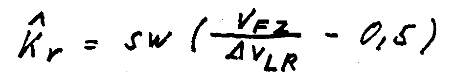
mit sw: Spurweite des FZ an VA
- ΔVLR:
- Funktion von Vorderradreferenzdifferenz und Hinterradreferenzdifferenz
Die beiden Schätzwerte V̂-Fz und k̂r werden einem Block 93 zugeführt, welcher als Ausgangsgröße p-min als unteren Begrenzungsdruck für den HA-Solldruck abgibt.
Dabei gilt die Beziehung:

wobei dei Konstanten konst1, konst2, konst3 und konst4 im Fahrversuch ermittelt werden - und zwar in der Hinsicht, daß in engen Kurven p-min ungefähr p-va-Niveau einnimmt (Fig. 9) (z.B.
Bei Unterschreitung einer bestimmten Geschwindigkeit Vgrenz wird ein Sollwertverlauf als Funkton von v -Fz in der Art vorgegeben, daß dieser nur für kritische Kurvenbremsungen (d.h. engere Kurven bei höheren Geschwindigkeiten) überschritten wird (Fig. 10).These upper and lower limits are made in a
The reference speeds v ref ascertained in the
The FZ speed is monitored by the pressure signals and to estimate the "tightness of the curve" according to the relationship
with sw: gauge of the FZ to VA
- ΔV LR :
- Function of front wheel reference difference and rear wheel reference difference
The two estimated values V̂-Fz and k̂r are fed to a block 93, which outputs the output variable p-min as the lower limiting pressure for the HA target pressure.
The relationship applies:
the constants const1, const2, const3 and const4 being determined in the driving test - specifically in the sense that p-min assumes approximately the p-va level in tight curves (FIG. 9) (eg constant 1 = 20 [m], Const 2 = 1 [m / sec] Const 3 = 1 [m / s], Const 4 = 0 [bar]
If a certain speed V limit is undershot , a setpoint curve is specified as a function of v -Fz in such a way that it is only exceeded for critical corner braking (ie tighter curves at higher speeds) (FIG. 10).
Im unterlagerten Druckregelkreis wird der anliegende Hinterachs-Druck auf den im Radgeschwindigkeitsregeler ermittelten Solldruck p-korr geregelt. Dazu wird der gemessene Hinterachs-Druck p-ha mit dem errechneten Solldruck p-korr im Verleicher 91 verglichen und diese Differenz einem Druckregeler 85 zugeführte, welcher ein Proportional-Integralübertragunsverhalten besitzt.In the lower-level pressure control circuit, the applied rear axle pressure is regulated to the target pressure p-corr determined in the wheel speed controller. For this purpose, the measured rear axle pressure p-ha is compared with the calculated target pressure p-corr in
Die Regelstrecke umfaßt hier die Komponente Hinterachsventil. Da entsprechend der Druck-Volumen-Kernlinie der Bremsanlage die bei einer bestimmten Ventilansteuerzeit erzielte Druckänderung von Druckniveau im Radbremszylinder selbst und von der Temperatur abhängt, wird dieser Druckgradient in einem Identifikationsglied 95 ermittelt gemäß folgender Beziehungen:
Es muß hierbei zwischen Druckauf- und Druckabbau unterschieden werden, weil dabei unterschiedliche Druckänderungsgeschwindigkeiten wirken. Diese nach obigen Gleichungen ermittelte Streckanverstärkung wird als Reziprogwert für die Proportionalverstärkung des Druckregelers 85 verwendet (Verstärkungskorrektur Block 86). Damit hat das Regelgesetz des Druckreglers folgendes Aussehen:
Die für Druckaufbau und Druckabbau jeweils geltenden Ventilansprechzeiten tp,tm (aus dem Schätzblock 87) werden in einem Addierer 88 durch Addition zu der errechneten Netto-Ventilansteuerzeit berücksichtigt.
Die Ventilansprechzeiten werden in Block 87 mittels eines (starken) Filters 1. Ordnung gemäß den Beziehungen
(ktp und ktm liegen im Berich zwischen 1 und 5). abgeschätzt und aktualisiert.
Dabei sind ktp u. ktm Verstärkungsfaktoren, die im Fahrversuch hinsichtlich guten Führungsverhaltens des Druckreglers einzustellen sind. Diese Errechnung der Ventilanspechzeiten bringt den wesentlichen Vorteil, daß Streuungen in den Ventilasnprechzeiten und zeitlich sich ändernde Ansprechzeiten (z.B. durch "Ventilalterung") berücksichtigt und entsprechend korrigiert werden.The controlled system here includes the component rear axle valve. Since, in accordance with the pressure-volume core line of the brake system, the pressure change achieved at a specific valve actuation time depends on the pressure level in the wheel brake cylinder itself and on the temperature, this pressure gradient is determined in an
A distinction must be made here between pressure build-up and pressure reduction, because different pressure change speeds act. This stretching gain, determined according to the above equations, is used as the reciprocal value for the proportional gain of the pressure regulator 85 (gain correction block 86). The control law of the pressure regulator thus has the following appearance:
The valve response times tp, tm (from the estimation block 87) that apply to pressure build-up and pressure reduction are taken into account in an
The valve response times are determined in
(ktp and ktm are between 1 and 5 in the range). estimated and updated.
Here are ktp u. ktm Gain factors that have to be set in the driving test with regard to good control behavior of the pressure regulator. This calculation of the valve response times has the essential advantage that scatter in the valve response times and time-changing response times (eg due to "valve aging") are taken into account and corrected accordingly.
Über den Schalter 105 kann eine Umschaltung zwischen der erfindungsgemäßen Druck- und der ABS-Regelung für die Hinterachse erfolgen. Dabei gilt folgende Übergangslogik:
Im Teilbremsbereich, d.h. wenn noch kein Vorderrad die ABS-Ansprechschwelle erreicht hat, wird die HA gemäß der Erfindung gergelt.Switch 105 can be used to switch between the pressure control and the ABS control for the rear axle. The following transition logic applies:
In the partial braking range, ie if no front wheel has yet reached the ABS threshold, the HA is governed according to the invention.
Bedingungen für den Einstieg in ABS-Regelung sind:
Erst wenn ein Vorderrad bereits in ABS-Regelung ist und das andere Vorderrad auch schon eine bestimmte Filterzeit-Druck-Abbau verlangte, wird umgeschaltet.Conditions for entering ABS control are:
Only when a front wheel is already in ABS control and the other front wheel has already requested a certain filter time pressure reduction is it switched over.
Bedingungen für den Ansstieg aus ABS sind:
Wenn die errechnete Ventilansteuerzeit eines Vorderrads über eine bestimmte Zeit die maximale Öffnungszeit ( Zykluszeit;hier: 20 ms) überschreitet (d.h. Vordurck zu gering ist oder
wenn beide Vorderräder eine bestimmte Minimalgeschwindigkeit unterschritten haben, wird rückgeschaltet.
Es werden vorzugsweise stets - sowohl im Teilbremsbereich als auch im ABS-Fall als auch während der jeweiligen Übergänge- beide Algorithmen durchlaufen (ABS und Druckregelung). Entsprechend der oben beschriebenen Logik wird dann die maßgebende Ventilansteuerzeit, also entweder die im ABS-Regler errechnete oder die im Druck-Regler errechnete, zur Ansteuerung der Ventiltreiber herangezogen.Conditions for getting out of ABS are:
If the calculated valve actuation time of a front wheel exceeds the maximum opening time (cycle time; here: 20 ms) over a certain time (ie pre-pressure is too low or
when both front wheels have fallen below a certain minimum speed, it shifts down.
Both algorithms (ABS and pressure control) are preferably always run through - both in the partial braking area and in the ABS case and during the respective transitions. In accordance with the logic described above, the decisive valve actuation time, that is to say either the one calculated in the ABS controller or the one calculated in the pressure controller, is then used to actuate the valve drivers.
p-soll, ha begrenzt auch im ABS-Betrieb den HA-Druck.p-should, ha limits the HA pressure even in ABS operation.
Claims (8)
Applications Claiming Priority (2)
| Application Number | Priority Date | Filing Date | Title |
|---|---|---|---|
| DE4112388A DE4112388A1 (en) | 1991-04-16 | 1991-04-16 | BRAKE PRESSURE CONTROL SYSTEM FOR A VEHICLE |
| DE4112388 | 1991-04-16 |
Publications (2)
| Publication Number | Publication Date |
|---|---|
| EP0509237A1 true EP0509237A1 (en) | 1992-10-21 |
| EP0509237B1 EP0509237B1 (en) | 1995-12-20 |
Family
ID=6429695
Family Applications (1)
| Application Number | Title | Priority Date | Filing Date |
|---|---|---|---|
| EP92104233A Expired - Lifetime EP0509237B1 (en) | 1991-04-16 | 1992-03-12 | Brake pressure controlling apparatus |
Country Status (4)
| Country | Link |
|---|---|
| US (1) | US5281012A (en) |
| EP (1) | EP0509237B1 (en) |
| JP (2) | JPH05116608A (en) |
| DE (2) | DE4112388A1 (en) |
Cited By (7)
| Publication number | Priority date | Publication date | Assignee | Title |
|---|---|---|---|---|
| EP0601480A1 (en) * | 1992-12-07 | 1994-06-15 | KNORR-BREMSE SYSTEME FÜR NUTZFAHRZEUGE GmbH | Automatic load dependent brake force controller for commercial vehicle |
| WO1994013517A1 (en) * | 1992-12-11 | 1994-06-23 | Robert Bosch Gmbh | Brake system |
| FR2699487A1 (en) * | 1992-12-23 | 1994-06-24 | Bosch Gmbh Robert | Braking system for a motor vehicle with distribution of the brake pressure on the axles of road vehicles. |
| FR2714006A1 (en) * | 1993-12-18 | 1995-06-23 | Bosch Gmbh Robert | Hydraulic brake system for road vehicles, especially passenger cars. |
| WO1996010507A1 (en) * | 1994-09-30 | 1996-04-11 | Itt Automotive Europe Gmbh | Hydraulic braking system and pressure-regulating method |
| WO1998025805A1 (en) * | 1996-12-11 | 1998-06-18 | Robert Bosch Gmbh | Process and device for controlling the braking force distribution in a vehicle |
| EP0768965B1 (en) * | 1995-03-24 | 2000-05-03 | Robert Bosch Gmbh | Process and device for controlling the braking system of a vehicle |
Families Citing this family (42)
| Publication number | Priority date | Publication date | Assignee | Title |
|---|---|---|---|---|
| US5547264A (en) * | 1992-11-04 | 1996-08-20 | Aisin Seiki Kabushiki Kaisha | Braking force distribution control system |
| DE4309243C2 (en) * | 1993-03-23 | 2003-07-03 | Continental Teves Ag & Co Ohg | Brake system with electronic control of the brake force distribution |
| DE4327208A1 (en) * | 1993-08-13 | 1995-02-16 | Teves Gmbh Alfred | Hydraulic dual circuit brake system |
| DE4334838A1 (en) * | 1993-10-13 | 1995-04-20 | Teves Gmbh Alfred | Brake system with electronic anti-lock control |
| DE4417935A1 (en) * | 1994-05-21 | 1995-11-23 | Teves Gmbh Alfred | Circuit arrangement for a brake system with electronic control of the brake force distribution |
| US5487598A (en) * | 1994-12-12 | 1996-01-30 | Alliedsignal Inc. | Variable duty cycle antilock braking system with accelerometer |
| DE19511161A1 (en) * | 1995-03-27 | 1996-10-02 | Bosch Gmbh Robert | Brake system for a motor vehicle |
| DE19511152A1 (en) | 1995-03-27 | 1996-10-02 | Bosch Gmbh Robert | Method and device for controlling the brake system of a vehicle |
| DE19518206B4 (en) * | 1995-05-18 | 2005-10-13 | Robert Bosch Gmbh | Method and device for controlling the brake system of a vehicle |
| US5632535A (en) * | 1995-08-28 | 1997-05-27 | Kelsey-Hayes Company | Dynamic rear proportioning brake system |
| DE19541601B4 (en) * | 1995-11-08 | 2007-08-09 | Robert Bosch Gmbh | Method and device for controlling the brake system of a vehicle |
| EP1026059B1 (en) * | 1995-12-26 | 2005-11-02 | Denso Corporation | Brake control apparatus for a vehicle |
| US6142581A (en) * | 1995-12-26 | 2000-11-07 | Denso Corporation | Hydraulic circuit having a rotary type pump and brake apparatus for a vehicle provided with the same |
| US6474751B1 (en) | 1995-12-26 | 2002-11-05 | Denso Corporation | Hydraulic circuit having a rotary type pump and brake apparatus for a vehicle provided with the same |
| DE19614630A1 (en) * | 1996-04-13 | 1997-10-16 | Teves Gmbh Alfred | Brake system with electronic brake force distribution |
| DE69707963T2 (en) * | 1996-04-26 | 2002-07-11 | Denso Corp., Kariya | Brake device for a motor vehicle |
| DE19653230B4 (en) * | 1996-12-20 | 2012-03-15 | Robert Bosch Gmbh | Method and device for controlling the brake system of a vehicle |
| DE19701070A1 (en) * | 1997-01-15 | 1998-07-16 | Bosch Gmbh Robert | Hydraulic vehicle brake system |
| DE19705619A1 (en) * | 1997-02-14 | 1998-08-20 | Bosch Gmbh Robert | Method and device for controlling the brake force distribution in a motor vehicle |
| DE69729717T2 (en) * | 1997-03-07 | 2005-08-04 | Same Deutz-Fahr Group S.P.A., Treviglio | Brake control system for agricultural tractors |
| DE19712889A1 (en) * | 1997-03-27 | 1998-10-01 | Bosch Gmbh Robert | Method and device for determining a quantity describing the system pressure in a brake circuit |
| JPH10278767A (en) * | 1997-04-09 | 1998-10-20 | Akebono Brake Ind Co Ltd | Brake liquid pressure control device |
| DE19749005A1 (en) | 1997-06-30 | 1999-01-07 | Bosch Gmbh Robert | Method and device for regulating movement variables representing vehicle movement |
| DE19733379B4 (en) * | 1997-08-01 | 2005-03-10 | Bosch Gmbh Robert | Device for controlling a brake system |
| GB9811585D0 (en) * | 1998-06-01 | 1998-07-29 | Delphi France Automotive Sys | Method for controlling vehicle behaviour during cornering and a braking system for implementation thereof |
| US6658343B1 (en) * | 1999-09-16 | 2003-12-02 | Robert Bosch Gmbh | Method and device for stabilizing a vehicle equipped with a slip-controlled brake system |
| DE19955094A1 (en) * | 1999-11-16 | 2001-05-23 | Siemens Ag | Motor vehicle braking control method |
| GB2360336B (en) * | 2000-03-14 | 2004-02-04 | Rover Group | Vehicle braking |
| JP2002037044A (en) * | 2000-07-27 | 2002-02-06 | Aisin Seiki Co Ltd | Vehicle front / rear braking force distribution control device |
| DE10234366B3 (en) * | 2002-07-27 | 2004-03-04 | Daimlerchrysler Ag | Brake pressure control device |
| US20050067884A1 (en) * | 2003-09-25 | 2005-03-31 | Clark James R. | Brake balance system for tandem axles |
| DE502005011165D1 (en) * | 2004-09-24 | 2011-05-05 | Continental Teves Ag & Co Ohg | METHOD FOR SUPPORTING A BRAKE SYSTEM WITH REDUCING THE EFFICIENCY OF THE VEHICLE BRAKING SYSTEM |
| US7809486B2 (en) * | 2005-04-29 | 2010-10-05 | Kelsey-Hayes Company | Pressure boost for vehicle rear brake circuits |
| NL1030943C2 (en) * | 2006-01-18 | 2007-07-19 | Tomtom Int Bv | Method for storing the position of a parked vehicle and navigation device adapted for that purpose. |
| JP4413931B2 (en) * | 2007-01-18 | 2010-02-10 | 株式会社日立製作所 | Vehicle and vehicle control device |
| DE102008041353A1 (en) * | 2008-08-19 | 2010-02-25 | Robert Bosch Gmbh | Method for compensating changes in volume of a hydraulic fluid in a hydraulic actuator for actuating a clutch, and hydraulic actuator |
| US8868281B2 (en) * | 2010-10-28 | 2014-10-21 | GM Global Technology Operations LLC | Understeer assessment for vehicles |
| KR102111909B1 (en) * | 2013-11-21 | 2020-05-18 | 현대모비스 주식회사 | Electronic hydraulic brake system |
| DE102015010400A1 (en) | 2015-08-11 | 2017-02-16 | Günter Fendt | Active level braking device for a vehicle, and method for an active level braking device |
| DE102016201179B4 (en) * | 2016-01-27 | 2021-04-15 | Ford Global Technologies, Llc | Method for operating a brake system of a motor vehicle and a brake system for a motor vehicle |
| CN113830042A (en) * | 2020-06-24 | 2021-12-24 | 广州汽车集团股份有限公司 | A vehicle braking control method and system |
| US11767003B2 (en) | 2020-12-14 | 2023-09-26 | Continental Automotive Systems, Inc. | By-wire brake system for motor vehicles |
Citations (4)
| Publication number | Priority date | Publication date | Assignee | Title |
|---|---|---|---|---|
| DE3323402A1 (en) * | 1983-04-07 | 1984-10-18 | Alfred Teves Gmbh, 6000 Frankfurt | BRAKE SYSTEM FOR MOTOR VEHICLES |
| US4962971A (en) * | 1987-11-19 | 1990-10-16 | Akebono Brake Industry Co., Ltd. | Anti-skid control system for motor vehicles |
| DE3923955A1 (en) * | 1989-07-19 | 1991-01-31 | Lucas Ind Plc | Antilocking braking system for double axle vehicle - has circuit evaluating RPM and determining rotation retardation of wheels and pressure control |
| DE4007360A1 (en) * | 1990-03-08 | 1991-09-12 | Daimler Benz Ag | METHOD FOR DISTRIBUTING BRAKE PRESSURE ON THE AXLES OF A MOTOR VEHICLE WITH ABS PRESSURE BRAKE |
Family Cites Families (24)
| Publication number | Priority date | Publication date | Assignee | Title |
|---|---|---|---|---|
| US3574415A (en) * | 1968-08-26 | 1971-04-13 | Rockwell Standard Co | Brake system |
| FR2067882A5 (en) * | 1969-11-20 | 1971-08-20 | Dba | |
| US3608978A (en) * | 1970-05-01 | 1971-09-28 | Rockwell Standard Co | Antiskid brake control |
| BE794514A (en) * | 1972-02-08 | 1973-05-16 | Citroen Sa | IMPROVEMENTS MADE TO THE BRAKE CONTROL DEVICES OF A VEHICLE |
| DE2327508A1 (en) * | 1973-05-30 | 1974-12-19 | Teldix Gmbh | VEHICLE BRAKING SYSTEM |
| DE2411096A1 (en) * | 1974-03-08 | 1975-09-18 | Daimler Benz Ag | PROCESS AND EQUIPMENT FOR CONTROLLING A TWO-CIRCUIT BRAKE SYSTEM FOR VEHICLES |
| DE3240275A1 (en) * | 1982-10-30 | 1984-05-03 | Robert Bosch Gmbh, 7000 Stuttgart | Device for load-dependent braking force control |
| DE3301948A1 (en) * | 1983-01-21 | 1984-07-26 | Alfred Teves Gmbh, 6000 Frankfurt | METHOD AND DEVICE FOR CONTROLLING THE BRAKING DISTRIBUTION |
| DE3302642C2 (en) * | 1983-01-27 | 1986-09-04 | Daimler-Benz Ag, 7000 Stuttgart | Anti-lock braking system for a two-wheeled road vehicle with a hydraulic dual-circuit braking system |
| DE3306611A1 (en) * | 1983-02-25 | 1984-08-30 | Alfred Teves Gmbh, 6000 Frankfurt | METHOD AND DEVICE FOR CONTROLLING THE BRAKING DISTRIBUTION |
| JPH0613287B2 (en) * | 1984-05-21 | 1994-02-23 | 日産自動車株式会社 | Vehicle braking force control device |
| DE3602432A1 (en) * | 1986-01-28 | 1987-07-30 | Bosch Gmbh Robert | ANTI-BLOCKING CONTROL SYSTEM |
| DE3700742C1 (en) * | 1987-01-13 | 1988-06-23 | Hans Deinlein-Kalb | Control system for the start-up and brake slip control of two-wheeled vehicles |
| DE3721210A1 (en) * | 1987-06-26 | 1989-01-05 | Rexroth Mannesmann Gmbh | Arrangement for regulating the brake pressure |
| DE3723916A1 (en) * | 1987-07-18 | 1989-01-26 | Daimler Benz Ag | HYDRAULIC TWO-CIRCUIT BRAKE SYSTEM |
| DE3741310A1 (en) * | 1987-12-05 | 1989-06-15 | Bosch Gmbh Robert | ANTI-BLOCKING PROTECTION AND SLIP CONTROL SYSTEM |
| DE3802133A1 (en) * | 1988-01-26 | 1989-08-03 | Daimler Benz Ag | DRIVE SLIP CONTROL DEVICE |
| DE3814045C2 (en) * | 1988-04-26 | 1996-08-08 | Teves Gmbh Alfred | Slip-controlled hydraulic brake system |
| US4850650A (en) * | 1988-09-02 | 1989-07-25 | General Motors Corporation | Hierarchical brake controller |
| US5042884A (en) * | 1988-11-25 | 1991-08-27 | Lucas Industries Public Limited Company | Hydraulic braking systems for vehicles |
| JP2980920B2 (en) * | 1989-08-03 | 1999-11-22 | 日本エービーエス株式会社 | Vehicle hydraulic brake control device |
| DE4010410A1 (en) * | 1990-03-31 | 1991-10-02 | Bosch Gmbh Robert | HYDRAULIC TWO-CIRCUIT BRAKE SYSTEM |
| JP2650459B2 (en) * | 1990-04-06 | 1997-09-03 | トヨタ自動車株式会社 | Acceleration slip control device |
| DE4016560A1 (en) * | 1990-05-23 | 1991-11-28 | Bosch Gmbh Robert | HYDRAULIC BRAKE SYSTEM |
-
1991
- 1991-04-16 DE DE4112388A patent/DE4112388A1/en not_active Withdrawn
-
1992
- 1992-03-12 DE DE59204719T patent/DE59204719D1/en not_active Expired - Lifetime
- 1992-03-12 EP EP92104233A patent/EP0509237B1/en not_active Expired - Lifetime
- 1992-04-16 JP JP4096654A patent/JPH05116608A/en active Pending
- 1992-04-16 US US07/870,047 patent/US5281012A/en not_active Expired - Lifetime
-
2003
- 2003-09-04 JP JP2003270996U patent/JP2004000005U/en active Pending
Patent Citations (4)
| Publication number | Priority date | Publication date | Assignee | Title |
|---|---|---|---|---|
| DE3323402A1 (en) * | 1983-04-07 | 1984-10-18 | Alfred Teves Gmbh, 6000 Frankfurt | BRAKE SYSTEM FOR MOTOR VEHICLES |
| US4962971A (en) * | 1987-11-19 | 1990-10-16 | Akebono Brake Industry Co., Ltd. | Anti-skid control system for motor vehicles |
| DE3923955A1 (en) * | 1989-07-19 | 1991-01-31 | Lucas Ind Plc | Antilocking braking system for double axle vehicle - has circuit evaluating RPM and determining rotation retardation of wheels and pressure control |
| DE4007360A1 (en) * | 1990-03-08 | 1991-09-12 | Daimler Benz Ag | METHOD FOR DISTRIBUTING BRAKE PRESSURE ON THE AXLES OF A MOTOR VEHICLE WITH ABS PRESSURE BRAKE |
Cited By (8)
| Publication number | Priority date | Publication date | Assignee | Title |
|---|---|---|---|---|
| EP0601480A1 (en) * | 1992-12-07 | 1994-06-15 | KNORR-BREMSE SYSTEME FÜR NUTZFAHRZEUGE GmbH | Automatic load dependent brake force controller for commercial vehicle |
| WO1994013517A1 (en) * | 1992-12-11 | 1994-06-23 | Robert Bosch Gmbh | Brake system |
| FR2699487A1 (en) * | 1992-12-23 | 1994-06-24 | Bosch Gmbh Robert | Braking system for a motor vehicle with distribution of the brake pressure on the axles of road vehicles. |
| FR2714006A1 (en) * | 1993-12-18 | 1995-06-23 | Bosch Gmbh Robert | Hydraulic brake system for road vehicles, especially passenger cars. |
| WO1996010507A1 (en) * | 1994-09-30 | 1996-04-11 | Itt Automotive Europe Gmbh | Hydraulic braking system and pressure-regulating method |
| US6082830A (en) * | 1994-09-30 | 2000-07-04 | Itt Mfg Emterprises Inc | Brake system having variable pump pressure control and method of pressure control |
| EP0768965B1 (en) * | 1995-03-24 | 2000-05-03 | Robert Bosch Gmbh | Process and device for controlling the braking system of a vehicle |
| WO1998025805A1 (en) * | 1996-12-11 | 1998-06-18 | Robert Bosch Gmbh | Process and device for controlling the braking force distribution in a vehicle |
Also Published As
| Publication number | Publication date |
|---|---|
| US5281012A (en) | 1994-01-25 |
| JP2004000005U (en) | 2004-02-05 |
| JPH05116608A (en) | 1993-05-14 |
| EP0509237B1 (en) | 1995-12-20 |
| DE59204719D1 (en) | 1996-02-01 |
| DE4112388A1 (en) | 1992-10-22 |
Similar Documents
| Publication | Publication Date | Title |
|---|---|---|
| EP0509237B1 (en) | Brake pressure controlling apparatus | |
| DE60311566T2 (en) | Vehicle braking system and method for its regulation | |
| DE69229634T2 (en) | METHOD AND DEVICE FOR REGULATING THE BRAKE FORCE OF THE REAR WHEELS | |
| DE112005001226B4 (en) | Brake force control system for vehicles | |
| DE102016013054A1 (en) | Method for adjusting brake pressures of a vehicle, brake system for carrying out the method and vehicle | |
| DE102006000145A1 (en) | Brake control device for a vehicle | |
| DE102005013741A1 (en) | Automatic deceleration control device for a vehicle | |
| DE4121747A1 (en) | DRIVE SLIP CONTROL FOR A MOTOR VEHICLE | |
| DE19502384A1 (en) | System for calculating estimated vehicle speed from wheel-speeds | |
| DE69508164T2 (en) | Brake pressure control device for motor vehicles | |
| DE69502298T2 (en) | Method for calculating the wheel reference speed in an anti-lock braking system | |
| DE102009046629A1 (en) | Control device for a braking device | |
| DE19838179A1 (en) | Vehicle braking control | |
| DE69208433T2 (en) | Method for regulating the rear wheel braking force and device therefor | |
| DE10225870B4 (en) | Vehicle brake control device and method | |
| DE19624491C2 (en) | Device for controlling the braking force distribution of a vehicle | |
| EP1888387B1 (en) | Brake circuit for a hydraulic braking system, braking system with such a brake circuit and a method for controlling a hydraulic braking system of a terrestrial vehicle | |
| DE4208581A1 (en) | Brake press control for road vehicle front and rear braking circuits - has antilocking and drive slip regulation with defined brake force ratio between front and rear braking circuits | |
| DE4128087A1 (en) | BRAKE PRESSURE CONTROL SYSTEM FOR A VEHICLE | |
| DE19607185A1 (en) | Procedure for ensuring neutral driving behavior when cornering and simultaneous load changes | |
| DE69219489T2 (en) | Traction control system for motor vehicles | |
| DE19542294B4 (en) | Slip control for traction control | |
| DE4105490C2 (en) | Slip control system for a motor vehicle | |
| DE19834167B4 (en) | Method and device for adjusting the braking power to current wheel-road-traction conditions | |
| EP0837803B1 (en) | Hydraulic vehicle braking system |
Legal Events
| Date | Code | Title | Description |
|---|---|---|---|
| PUAI | Public reference made under article 153(3) epc to a published international application that has entered the european phase |
Free format text: ORIGINAL CODE: 0009012 |
|
| AK | Designated contracting states |
Kind code of ref document: A1 Designated state(s): DE FR IT SE |
|
| 17P | Request for examination filed |
Effective date: 19930326 |
|
| 17Q | First examination report despatched |
Effective date: 19940420 |
|
| GRAA | (expected) grant |
Free format text: ORIGINAL CODE: 0009210 |
|
| AK | Designated contracting states |
Kind code of ref document: B1 Designated state(s): DE FR IT SE |
|
| ET | Fr: translation filed | ||
| REF | Corresponds to: |
Ref document number: 59204719 Country of ref document: DE Date of ref document: 19960201 |
|
| ITF | It: translation for a ep patent filed | ||
| PLBE | No opposition filed within time limit |
Free format text: ORIGINAL CODE: 0009261 |
|
| STAA | Information on the status of an ep patent application or granted ep patent |
Free format text: STATUS: NO OPPOSITION FILED WITHIN TIME LIMIT |
|
| 26N | No opposition filed | ||
| PGFP | Annual fee paid to national office [announced via postgrant information from national office to epo] |
Ref country code: SE Payment date: 20040322 Year of fee payment: 13 |
|
| PG25 | Lapsed in a contracting state [announced via postgrant information from national office to epo] |
Ref country code: IT Free format text: LAPSE BECAUSE OF NON-PAYMENT OF DUE FEES;WARNING: LAPSES OF ITALIAN PATENTS WITH EFFECTIVE DATE BEFORE 2007 MAY HAVE OCCURRED AT ANY TIME BEFORE 2007. THE CORRECT EFFECTIVE DATE MAY BE DIFFERENT FROM THE ONE RECORDED. Effective date: 20050312 |
|
| PG25 | Lapsed in a contracting state [announced via postgrant information from national office to epo] |
Ref country code: SE Free format text: LAPSE BECAUSE OF NON-PAYMENT OF DUE FEES Effective date: 20050313 |
|
| EUG | Se: european patent has lapsed | ||
| PGFP | Annual fee paid to national office [announced via postgrant information from national office to epo] |
Ref country code: FR Payment date: 20110401 Year of fee payment: 20 |
|
| PGFP | Annual fee paid to national office [announced via postgrant information from national office to epo] |
Ref country code: DE Payment date: 20110525 Year of fee payment: 20 |
|
| REG | Reference to a national code |
Ref country code: DE Ref legal event code: R071 Ref document number: 59204719 Country of ref document: DE |
|
| REG | Reference to a national code |
Ref country code: DE Ref legal event code: R071 Ref document number: 59204719 Country of ref document: DE |
|
| PG25 | Lapsed in a contracting state [announced via postgrant information from national office to epo] |
Ref country code: DE Free format text: LAPSE BECAUSE OF EXPIRATION OF PROTECTION Effective date: 20120313 |