EP0370174B1 - Capteur inductif de rotation pour débitmètre à turbine - Google Patents
Capteur inductif de rotation pour débitmètre à turbine Download PDFInfo
- Publication number
- EP0370174B1 EP0370174B1 EP89115004A EP89115004A EP0370174B1 EP 0370174 B1 EP0370174 B1 EP 0370174B1 EP 89115004 A EP89115004 A EP 89115004A EP 89115004 A EP89115004 A EP 89115004A EP 0370174 B1 EP0370174 B1 EP 0370174B1
- Authority
- EP
- European Patent Office
- Prior art keywords
- coil
- coils
- pulse
- flip
- impeller wheel
- Prior art date
- Legal status (The legal status is an assumption and is not a legal conclusion. Google has not performed a legal analysis and makes no representation as to the accuracy of the status listed.)
- Expired - Lifetime
Links
- 230000001939 inductive effect Effects 0.000 title claims description 22
- 238000013016 damping Methods 0.000 claims abstract description 21
- 239000003990 capacitor Substances 0.000 claims abstract description 11
- 238000001208 nuclear magnetic resonance pulse sequence Methods 0.000 claims description 9
- 238000011156 evaluation Methods 0.000 abstract description 6
- 230000010355 oscillation Effects 0.000 description 6
- 238000010586 diagram Methods 0.000 description 5
- 239000002184 metal Substances 0.000 description 3
- 238000004804 winding Methods 0.000 description 3
- 238000012512 characterization method Methods 0.000 description 2
- 238000005265 energy consumption Methods 0.000 description 2
- 230000004907 flux Effects 0.000 description 2
- XLYOFNOQVPJJNP-UHFFFAOYSA-N water Substances O XLYOFNOQVPJJNP-UHFFFAOYSA-N 0.000 description 2
- 239000004020 conductor Substances 0.000 description 1
- 238000010276 construction Methods 0.000 description 1
- 230000001419 dependent effect Effects 0.000 description 1
- 238000001514 detection method Methods 0.000 description 1
- 230000005284 excitation Effects 0.000 description 1
- 230000007774 longterm Effects 0.000 description 1
- 238000004519 manufacturing process Methods 0.000 description 1
- 238000005259 measurement Methods 0.000 description 1
- 230000001681 protective effect Effects 0.000 description 1
- 239000010453 quartz Substances 0.000 description 1
- VYPSYNLAJGMNEJ-UHFFFAOYSA-N silicon dioxide Inorganic materials O=[Si]=O VYPSYNLAJGMNEJ-UHFFFAOYSA-N 0.000 description 1
Images


Classifications
-
- G—PHYSICS
- G01—MEASURING; TESTING
- G01F—MEASURING VOLUME, VOLUME FLOW, MASS FLOW OR LIQUID LEVEL; METERING BY VOLUME
- G01F1/00—Measuring the volume flow or mass flow of fluid or fluent solid material wherein the fluid passes through a meter in a continuous flow
- G01F1/05—Measuring the volume flow or mass flow of fluid or fluent solid material wherein the fluid passes through a meter in a continuous flow by using mechanical effects
- G01F1/10—Measuring the volume flow or mass flow of fluid or fluent solid material wherein the fluid passes through a meter in a continuous flow by using mechanical effects using rotating vanes with axial admission
- G01F1/115—Measuring the volume flow or mass flow of fluid or fluent solid material wherein the fluid passes through a meter in a continuous flow by using mechanical effects using rotating vanes with axial admission with magnetic or electromagnetic coupling to the indicating device
-
- G—PHYSICS
- G01—MEASURING; TESTING
- G01F—MEASURING VOLUME, VOLUME FLOW, MASS FLOW OR LIQUID LEVEL; METERING BY VOLUME
- G01F1/00—Measuring the volume flow or mass flow of fluid or fluent solid material wherein the fluid passes through a meter in a continuous flow
- G01F1/05—Measuring the volume flow or mass flow of fluid or fluent solid material wherein the fluid passes through a meter in a continuous flow by using mechanical effects
- G01F1/06—Measuring the volume flow or mass flow of fluid or fluent solid material wherein the fluid passes through a meter in a continuous flow by using mechanical effects using rotating vanes with tangential admission
- G01F1/075—Measuring the volume flow or mass flow of fluid or fluent solid material wherein the fluid passes through a meter in a continuous flow by using mechanical effects using rotating vanes with tangential admission with magnetic or electromagnetic coupling to the indicating device
-
- G—PHYSICS
- G01—MEASURING; TESTING
- G01F—MEASURING VOLUME, VOLUME FLOW, MASS FLOW OR LIQUID LEVEL; METERING BY VOLUME
- G01F15/00—Details of, or accessories for, apparatus of groups G01F1/00 - G01F13/00 insofar as such details or appliances are not adapted to particular types of such apparatus
- G01F15/06—Indicating or recording devices
- G01F15/068—Indicating or recording devices with electrical means
Definitions
- the invention relates to an inductive rotation sensor for impeller flowmeters, with at least one stationary coil, by means of which an alternating field is generated, with an electrically conductive damping body rotating past the coil with the impeller of the flowmeter, an eddy current being generated by the alternating field of the coil in the damping body and thus an opposing field is generated, which reacts on the alternating field of the coil, and with an evaluation circuit processing the result of the reaction of the damping body.
- CH patent 509 573 it is stated as a generally known prior art that a movable construction element made of a conductive medium can be arranged in the magnetic field of a coil for measurement purposes. Eddy currents are induced in this medium, which in turn build up an opposing field, which reacts on the coil and causes a change in its electrical properties.
- a speed measuring device for an impeller flow meter has become known, which works according to the principle described above.
- a piece of metal is arranged on the impeller, which when rotating passes a pot coil inserted into a housing wall.
- the pot coil is part of a feedback transformer of a generator, the vibrations of which stop when the metal piece passes the pot coil and draws energy from it.
- a vibration detector converts the resulting vibration packets into rectangular pulses for further processing and to determine the speed of the impeller.
- the generator is constantly powered, whereby a field strength must be generated in the pot coil that is suitable for creating sufficiently strong eddy currents in the metal piece so that sufficient energy is withdrawn from the field of the pot coil and the oscillation tears off.
- WO 87/06354 discloses an inductive proximity sensor that can also be used for a water meter.
- an attenuator is provided which is coupled to the impeller of the water meter and rotates past the proximity sensor.
- the proximity sensor has a quartz oscillator and a divider circuit which generates DC voltage pulses.
- the DC voltage pulses are fed to an LC series resonant circuit, which is excited to a damped oscillation by each of the pulses.
- the damped vibration is inductively transferred to a secondary winding of a transformer, the primary winding of which forms the resonant circuit coil.
- the secondary winding is connected to an evaluation circuit, which consists of a discriminator circuit and a counter circuit.
- the discriminator circuit generates a pulse for each amplitude of the damped oscillation that exceeds a predetermined threshold value.
- the pulses occurring during each damped oscillation are counted and their number is compared with the number of pulses occurring in the undamped proximity sensor.
- the damping events determined in this way are displayed in a suitable manner.
- a flow measuring cell which has a gear wheel to which four magnetic elements are attached.
- Three inductive pickups are arranged at a predetermined distance from the gearwheel in such a way that the magnetic elements are guided past them when the gearwheel rotates, the magnetic flux being changed each time. From this an electrical signal is obtained, the frequency of which is used to determine the rotational speed.
- the transducers are each arranged by 4/3 of the division of the magnetic elements, so that a multiplication of the change frequency of the magnetic flux corresponding to the number of transducers can be achieved.
- the invention has for its object to provide an inexpensive and energy-saving inductive rotation sensor according to the preamble, starting from the prior art set out above, which not only detects the speed but also the direction of rotation and works without reaction.
- the invention characterized in claim 1.
- three coils are provided which are arranged concentrically around the axis of rotation of the impeller and which are connected in parallel via a capacitor.
- the resonant circuits formed in this way are simultaneously only intermittently excited to such an extent that the damping body can only increase the frequency of the voltage of the coil in question as it rotates past.
- the coil voltages are fed to an evaluation circuit, by means of which the speed and direction of rotation of the impeller are determined from the difference between the frequencies of the damped and undamped coils.
- 1 denotes a housing of an impeller flow meter, which is only indicated by dash-dotted lines, and 2 denotes an impeller.
- a damping body 3 made of electrically conductive material is connected to the impeller 2 in an insulated manner.
- three air coils L a , L b , L c which are arranged concentrically about the axis of rotation 4 of the impeller 2 and are offset by 120 °, are fastened, by means of which an alternating field 5 indicated by dashed lines is generated.
- 6 with dashed, concentric lines symbolized paths of an eddy current, which is caused by the alternating field 5 of the respective air coil L a , L b or L c in the damping body 3.
- the three air coils L a , L b , L c are each connected in parallel via a capacitor 10, 11, 12, so that three series resonant circuits connected in parallel are formed.
- One end of each of the air coils L a , L b , L c is connected via a rectifier arrangement 13 to an evaluation circuit which consists of a digitizing element 14, a phase discriminator 15 and a switching mechanism 16.
- the digitizing element 14 consists of a first, second and third Schmitt trigger 17, 18, 19, the inputs of which are connected to the ends of the air coils L a , L b , L c via the rectifier arrangement 13.
- the phase discriminator 15 has a first, second and third D flip-flop 20, 21, 22 on, whose data inputs D with inverting outputs S a , S b , S c the Schmitt trigger 17, 18, 19 are connected.
- the clock input C of the first D flip-flop 20 is at the inverting output S b of the second Schmitt trigger 18, the clock input C of the second D flip-flop 21 at the inverting output S c of the third Schmitt trigger 19, and the clock input C of the third D flip-flop 22 at the inverting output S a of the first Schmitt trigger 17 connected.
- the switching mechanism 16 is connected on the input side to a clock generator 23 and the outputs Q a , Q b , Q c of the D flip-flops 20, 21, 22.
- the switching mechanism 16 generates one pulse per revolution of the impeller 2 and has two outputs A r , A l , one output A r being assigned to the clockwise rotation and the other output A l to the counterclockwise rotation of the impeller 2.
- the pulses occurring at the respective output A r or A l depending on the direction of rotation are fed to a display device, not shown.
- a device 24 for generating supply voltage pulses SP is on the input side with the clock generator 23 and the inverting output S a of the first Schmitt trigger 17 connected and connected on the output side via the capacitors 10, 11, 12 to the air coils L a , L b , L c .
- the frequency of the supply voltage pulses SP is determined by the clock generator 23 and corresponds to three times the maximum speed of the impeller 2.
- the width of a supply voltage pulse results in each case from an edge of a clock generator pulse and the switch-off point of the first trigger pulse (time II, FIG. 5).
- the inductive rotation sensor described above works as follows: When a supply voltage pulse occurs, the series resonant circuits consisting of the air coils L a , L b , L c and capacitors 10, 11, 12 are excited simultaneously, with a damped cosine-shaped oscillation in each air coil arises (time I, Fig. 4-8). It may now be assumed that the damping body 3 is at the time of the excitation in the area of the one air coil L a (FIG. 2), so that an eddy current 6 is induced in the damping body 3, the field of which increases the damping and resonance frequency of the resonant circuit in question .
- the air coil L b is damped, with the inverting trigger outputs S a , S b , S c are set low (time V, FIG. 9).
- the first, second and third pulse sequences are then generated again and the output Q a of the first D flip-flop 20 is set low (Time VI, Fig. 9). Since the second pulse train acts as a data signal and the third pulse train acts as a clock signal when the air coil L b is damped, the output Q b of the second D flip-flop 21 is now raised (time VII, FIG.
- the switching mechanism 16 works in such a way that a pulse is generated per sequence of the signal states, or per revolution, which occurs at one or the other output A r , A l depending on the direction of rotation.
- the output A r assigned to the clockwise rotation is activated in the sequence 100 010 001 and the frequency of the pulses occurring here is interpreted by the display device as the maximum speed of the impeller 2.
- the speed of the impeller 2 corresponds to one third of the maximum speed.
- each air coil is damped several times during one revolution according to the selected shape of the damping body 3, the direction of rotation of the signal states specific to the direction of rotation being three times as slow (FIG. 11, clockwise rotation).
- only one pulse is generated per sequence, so that the frequency of the pulses occurring at the assigned output A r is three times smaller than the maximum frequency due to the slower sequence, so that the display device indicates a speed three times lower.
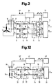
- the digitizing element 33 has a first and second Schmitt trigger 36, 37, the inputs of which are connected to the ends of the air coils L via the rectifier arrangement 32 ′ a , L ′ b stay in contact.
- the phase discriminator 34 consists of a first and second D flip-flop 38, 39, the data inputs D of which have inverting outputs S a , S b the Schmitt trigger 36, 37 are connected.
- the clock input C of the first D flip-flop 38 is at the inverting output S b of the second Schmitt trigger 37, and the clock input C of the second D flip-flop 39 at the inverting output S a of the first Schmitt trigger 36 connected.
- the switching mechanism 35 is connected on the input side to a clock generator 40 and the outputs Q a , Q b of the D flip-flops 38, 39.
- the switching mechanism 35 generates one pulse per revolution of the impeller and has an output A, via which the pulses are fed to a display device, not shown.
- a device 41 for generating supply voltage pulses is on the input side with the clock generator 40 and the inverting output S a of the first Schmitt trigger 36 connected and on the output side via the capacitors 30, 31 to the air coils L. ′ a , L ′ b connected.
- the frequency of the supply voltage pulses is determined by the clock generator 40 and corresponds to twice the maximum speed of the impeller.
Landscapes
- Physics & Mathematics (AREA)
- Fluid Mechanics (AREA)
- General Physics & Mathematics (AREA)
- Electromagnetism (AREA)
- Measuring Volume Flow (AREA)
- Indicating Or Recording The Presence, Absence, Or Direction Of Movement (AREA)
- Paper (AREA)
- Controlling Rewinding, Feeding, Winding, Or Abnormalities Of Webs (AREA)
- Regulating Braking Force (AREA)
- Ignition Installations For Internal Combustion Engines (AREA)
Claims (7)
- Détecteur de rotations inductif pour débitmètres à turbine, comportant au moins une bobine stationnaire à l'aide de laquelle est généré un champ alternatif, un corps amortisseur (3) électriquement conducteur qui passe en tournant avec la turbine (2) du débitmètre, devant la bobine, étant précisé que le champ alternatif de la bobine génère dans le corps amortisseur (3) un courant tourbillonnaire et, ainsi, un champ opposé agissant sur le champ alternatif de la bobine, et un circuit d'évaluation qui traite le résultat de la réaction du corps amortisseur (3), caractérisé- en ce qu'il est prévu trois bobines à air stationnaires (La, Lb, Lc) qui sont disposées de façon concentrique autour de l'axe de rotation (4) de la turbine (2), décalées de 120 °- en ce que les trois bobines (La, Lb, Lc) sont montées en parallèle par l'intermédiaire de condensateurs respectifs (10, 11, 12), étant précisé que la première extrémité des trois bobines (La, Lb, Lc) est à la masse tandis que leur seconde extrémité est reliée au circuit d'évaluation et, par l'intermédiaire des condensateurs (10, 11, 12), à un dispositif (24) qui est destiné à générer des impulsions de tension d'alimentation (SP) et qui est raccordé, côté entrée, à un synchroniseur (23),- en ce que les bobines (La, Lb, Lc) sont alimentées, d'une manière connue en soi, de façon intermittente, étant précisé que la fréquence des impulsions de tension d'alimentation (SP) correspond à un multiple du nombre de tours maximal de la turbine (2), et- que la fréquence de la tension est augmentée sur la bobine devant laquelle le corps amortisseur (3) passe en tournant, et- en ce qu'il est prévu, dans le circuit d'évaluation, un élément de numérisation (14) qui génère des trains d'impulsions correspondant aux courbes de tension des bobines (La, Lb, Lc), étant précisé que le train d'impulsions de la bobine amortie à chaque fois possède une fréquence supérieure à celle des trains d'impulsions des bobines non amorties, et que pendant une rotation, le sens de rotation et le nombre de tours de la turbine (2) peuvent être calculés à partir des changements successifs de position relative des impulsions de la bobine amortie par rapport aux impulsions des bobines non amorties.
- Détecteur de rotations inductif pour débitmètres à turbine, comportant au moins une bobine stationnaire à l'aide de laquelle est généré un champ alternatif, un corps amortisseur électriquement conducteur qui passe, en tournant avec la turbine du débitmètre, devant la bobine, étant précisé que le champ alternatif de la bobine générant dans le corps amortisseur un courant tourbillonnaire et, ainsi, un champ opposé agissant sur le champ alternatif de la bobine, et un circuit d'évaluation qui traite le résultat de la réaction du corps amortisseur, caractérisé- en ce qu'il est prévu deux bobines stationnaires (La′, Lb′) qui sont disposées sur un diamètre de la turbine, de façon symétrique par rapport à l'axe de rotation de la turbine,- en ce que les deux bobines (La′, Lb′) sont montées en parallèle par l'intermédiaire de condensateurs respectifs (30, 31), étant précisé que la première extrémité des deux bobines (La′, Lb′) est à la masse tandis que leur seconde extrémité est reliée au circuit d'évaluation et, par l'intermédiaire des condensateurs (30, 31), à un dispositif (41) qui est destiné à générer des impulsions de tension d'alimentation (SP) et qui est raccordé, côté entrée, à un synchroniseur (40),- en ce que les bobines (La′, Lb′) sont alimentées, d'une manière connue en soi, de façon intermittente, étant précisé que la fréquence des impulsions de tension d'alimentation (SP) correspond à un multiple du nombre de tours maximal de la turbine, et- que la fréquence de la tension est augmentée sur la bobine devant laquelle le corps amortisseur passe en tournant, et- en ce qu'il est prévu, dans le circuit d'évaluation, un élément de numérisation (33) qui génère des trains d'impulsions correspondant aux courbes de tension des bobines (La′, Lb′), étant précisé que le train d'impulsions de la bobine amortie à chaque fois possède une fréquence supérieure à celle du train d'impulsions de la bobine non amortie, et que pendant une rotation, le nombre de tours de la turbine peut être calculé à partir du changement de position relative des impulsions de la bobine amortie par rapport aux impulsions de la bobine non amorties.
- Détecteur de rotations inductif selon les revendications 1 et 2, caractérisé en ce que les extrémités des bobines sont raccordées au circuit d'évaluation par l'intermédiaire d'un dispositif redresseur (13, 32) de sorte que seules les amplitudes positives des tensions de bobines sont transmises.
- Détecteur de rotations inductif selon la revendication 3, caractérisé en ce que le circuit d'évaluation possède un discriminateur de phase (15, 34) et un mécanisme de commutation (16, 35) qui sont reliés, montés en série, à l'élément de numérisation (14, 33).
- Détecteur de rotations inductif selon la revendication 1 associée à la revendication 4, caractérisé- en ce que l'élément de numérisation (14) se compose d'une première, d'une seconde et d'une troisième bascule de Schmitt (17, 18, 19) dont les entrées sont reliées par l'intermédiaire du dispositif redresseur (13) aux extrémités des bobines à air (La, Lb, Lc),- en ce que le discriminateur de phase (15) possède des premier, second et troisième flip-flops D (20, 21, 22) dont les entrées de données (D) sont reliées à des sorties d'inversion (
S a,S b,S c) des bascules de Schmitt (17, 18, 19), et l'entrée de synchronisation (C) du premier flip-flop D (20) est reliée à la sortie d'inversion (S b) de la seconde bascule de Schmitt (18) tandis que l'entrée de synchronisation (C) du second flip-flop D (21) est reliée à la sortie d'inversion (S c) de la troisième bascule de Schmitt (19) et l'entrée de synchronisation (C) du troisième flip-flop D (22) est reliée à la sortie d'inversion (S a) de la première bascule de Schmitt (17),- en ce que le mécanisme de commutation (16) est relié, côté entrée, aux sorties (Qa, Qb, Qc) des flip-flops D (20, 21, 22) et au synchroniseur (23), et possède deux sorties (Ar, Al),- étant précisé que le mécanisme de commutation (16) génère une impulsion pour chaque tour de la turbine (2) et que les impulsions générées apparaissent à la première sortie (Ar) lors d'une rotation vers la droite, et à la seconde sortie (Al) lors d'une rotation vers la gauche. - Détecteur de rotations inductif selon la revendication 2 associée à la revendication 4, caractérisé- en ce que l'élément de numérisation (33) se compose d'une première et d'une seconde bascule de Schmitt (36, 37) dont les entrées sont reliées, par l'intermédiaire du dispositif redresseur (32), aux extrémités des bobines (La′, Lb′),- en ce que le discriminateur de phase (34) possède des premier et second flip-flops D (38, 39) dont les entrées de données (D) sont reliées à des sorties d'inversion (
S a,S b) des bascules de Schmitt (36, 37), et l'entrée de synchronisation (C) du premier flip-flop D (38) est reliée à la sortie d'inversion (S b) de la seconde bascule de Schmitt (37) tandis que l'entrée de synchronisation (C) du second flip-flop D (39) est reliée à la sortie d'inversion (S a) de la première bascule de Schmitt (36),- en ce que le mécanisme de commutation (35) est relié, côté entrée, aux sorties (Qa, Qb) des flip-flops D (38, 39) et au synchroniseur (40), et possède une entrée (A),- étant précisé que le mécanisme de commutation (35) génère une impulsion pour chaque tour de la turbine et que les impulsions générées apparaissent à la sortie (A). - Détecteur de rotations inductif selon les revendications 1 et 2, caractérisé en ce que les bobines (La, Lb, Lc et La′, Lb′) sont des bobines à air.
Priority Applications (1)
| Application Number | Priority Date | Filing Date | Title |
|---|---|---|---|
| AT89115004T ATE85425T1 (de) | 1988-10-27 | 1989-08-14 | Induktiver umdrehungssensor fuer fluegelraddurchflussmesser. |
Applications Claiming Priority (2)
| Application Number | Priority Date | Filing Date | Title |
|---|---|---|---|
| CH401788 | 1988-10-27 | ||
| CH4017/88 | 1988-10-27 |
Publications (2)
| Publication Number | Publication Date |
|---|---|
| EP0370174A1 EP0370174A1 (fr) | 1990-05-30 |
| EP0370174B1 true EP0370174B1 (fr) | 1993-02-03 |
Family
ID=4268259
Family Applications (1)
| Application Number | Title | Priority Date | Filing Date |
|---|---|---|---|
| EP89115004A Expired - Lifetime EP0370174B1 (fr) | 1988-10-27 | 1989-08-14 | Capteur inductif de rotation pour débitmètre à turbine |
Country Status (4)
| Country | Link |
|---|---|
| EP (1) | EP0370174B1 (fr) |
| AT (1) | ATE85425T1 (fr) |
| DE (1) | DE58903449D1 (fr) |
| DK (1) | DK529889A (fr) |
Cited By (2)
| Publication number | Priority date | Publication date | Assignee | Title |
|---|---|---|---|---|
| DE19538163C1 (de) * | 1995-10-13 | 1997-03-27 | Wehrle E Gmbh | Vorrichtung zur Drehzahl- und Drehrichtungserkennung mittels magnetfeldabhängiger Widerstandselemente |
| US6850054B2 (en) | 2000-08-09 | 2005-02-01 | Elster Messtechnik Gmbh | Device and a method for non-contacting sensing of the rotational state of a rotor |
Families Citing this family (9)
| Publication number | Priority date | Publication date | Assignee | Title |
|---|---|---|---|---|
| FR2664973B1 (fr) * | 1990-07-20 | 1992-10-23 | Schlumberger Ind Sa | Dispositif de detection de rotation d'un element tournant tel que la turbine d'un compteur d'eau. |
| DE4446918A1 (de) * | 1994-12-28 | 1996-07-04 | Spanner Pollux Gmbh | Induktiver Sensor zum Messen der Drehzahl oder Drehrichtung einer Welle |
| DE29906448U1 (de) * | 1999-04-12 | 1999-08-12 | Alfons Haar Maschinenbau Gmbh & Co, 22547 Hamburg | Sensor zur berührungslosen Messung der Drehung eines Rotors in einem Flüssigkeitsdurchflußmesser |
| DE10352251B4 (de) * | 2003-11-08 | 2019-10-24 | Elster Messtechnik Gmbh | Vorrichtung zur Führung und Positionierung von elektrischen Bauteilen |
| GB2429118A (en) * | 2005-07-26 | 2007-02-14 | Sensor Technology Ltd | Rotary signal coupler having inductive and capacitive elements in series |
| AT510531A1 (de) * | 2010-10-05 | 2012-04-15 | Kral Ag | Durchflussmesseinrichtung |
| DE202013001852U1 (de) * | 2013-02-27 | 2014-02-28 | Christian Gradischnik | Vorrichtung zum Erfassen eines Durchflusses |
| DE102013215604A1 (de) * | 2013-08-07 | 2015-02-12 | BSH Bosch und Siemens Hausgeräte GmbH | Durchflussmesser, Rotor und wasserführendes Haushaltsgerät |
| CN107747984B (zh) * | 2017-10-27 | 2019-11-19 | 深圳友讯达科技股份有限公司 | 参考电压修正方法及装置 |
Family Cites Families (6)
| Publication number | Priority date | Publication date | Assignee | Title |
|---|---|---|---|---|
| US3996800A (en) * | 1974-05-17 | 1976-12-14 | Combustion Engineering, Inc. | Turbine meter |
| JPS54141166A (en) * | 1978-04-25 | 1979-11-02 | Toukiyouto | Water meter |
| DE2943184A1 (de) * | 1979-10-25 | 1981-05-07 | AOA Apparatebau Gauting GmbH, 8035 Gauting | Durchflussmesszelle |
| EP0029336A1 (fr) * | 1979-11-15 | 1981-05-27 | Britax Vega Limited | Débitmètres |
| DE3611862A1 (de) * | 1986-04-09 | 1987-10-15 | Steudler Gmbh & Co Kg A | Induktiver naeherungssensor |
| DE3642678A1 (de) * | 1986-12-13 | 1988-06-16 | Bosch Gmbh Robert | Messeinrichtung fuer drehwinkel und/oder drehgeschwindigkeit |
-
1989
- 1989-08-14 AT AT89115004T patent/ATE85425T1/de not_active IP Right Cessation
- 1989-08-14 EP EP89115004A patent/EP0370174B1/fr not_active Expired - Lifetime
- 1989-08-14 DE DE8989115004T patent/DE58903449D1/de not_active Expired - Fee Related
- 1989-10-25 DK DK529889A patent/DK529889A/da not_active Application Discontinuation
Cited By (2)
| Publication number | Priority date | Publication date | Assignee | Title |
|---|---|---|---|---|
| DE19538163C1 (de) * | 1995-10-13 | 1997-03-27 | Wehrle E Gmbh | Vorrichtung zur Drehzahl- und Drehrichtungserkennung mittels magnetfeldabhängiger Widerstandselemente |
| US6850054B2 (en) | 2000-08-09 | 2005-02-01 | Elster Messtechnik Gmbh | Device and a method for non-contacting sensing of the rotational state of a rotor |
Also Published As
| Publication number | Publication date |
|---|---|
| EP0370174A1 (fr) | 1990-05-30 |
| DK529889A (da) | 1990-04-28 |
| DK529889D0 (da) | 1989-10-25 |
| ATE85425T1 (de) | 1993-02-15 |
| DE58903449D1 (de) | 1993-03-18 |
Similar Documents
| Publication | Publication Date | Title |
|---|---|---|
| EP0179384B1 (fr) | Commutateur de proximité insensible aux champs parasites | |
| DE2805935A1 (de) | Detektoreinrichtung | |
| EP0370174B1 (fr) | Capteur inductif de rotation pour débitmètre à turbine | |
| DE602004010486T2 (de) | Induktiver Annäherungssensor | |
| EP0132745B1 (fr) | Dispositif de mesure de courants continus | |
| DE3519215C2 (fr) | ||
| DE3611862A1 (de) | Induktiver naeherungssensor | |
| EP0311128B1 (fr) | Procédé et dispositif pour l'excitation d'un circuit résonnant | |
| DE2605764A1 (de) | Frequenzaenderungsvorrichtung, insbesondere zur verwendung in einem durchflussmesser | |
| DE3213602C2 (fr) | ||
| WO1989003616A1 (fr) | Detecteur inductif de proximite | |
| DE69805871T2 (de) | Längenmessapparat unter Verwendung einer magnetostriktiven Verzögerungsleitung | |
| DE4137695C2 (de) | Sensoranordnung zur Feststellung des Bewegungszustandes eines Rotors | |
| DE3133330C2 (de) | Magnetisch-induktiver Durchflußmesser | |
| DE3017202C2 (de) | Einrichtung zur Ermittlung der Drehzahl eines drehbaren oder der Frequenz eines linear schwingenden Bauteils aus magnetisch permeablem Material | |
| EP0045509B1 (fr) | Dispositif pour la détermination de l'intensité de champs magnétiques par exemple le champ terrestre | |
| DE3241222A1 (de) | Vorrichtung zur messung der drehzahl und ggf. der drehrichtung eines fluegelrades eines fluegelraddurchflussmessers fuer vorzugsweise elektrolytische fluessigkeiten | |
| EP1007909A1 (fr) | Detecteur a resonance magnetique | |
| DE2831598C2 (de) | Vorrichtung zur Weg- und Geschwindigkeitsmessung | |
| DE2837014C3 (de) | Anordnung zur Messung des Abstandes der Abstandsänderung sowie der Abstandsänderungsgeschwindigkeit zweier auf einer vorbestimmten Bewegungsbahn relativ zueinander bewegbarer Körper | |
| DE2931329A1 (de) | Anordnung zur bestimmung der drehrichtung einer welle | |
| EP0697769A1 (fr) | Détecteur de proximité magnétique | |
| EP0080055A2 (fr) | Capteur électromagnétique de déplacement | |
| EP0059770B1 (fr) | Dispositif pour enregistrer un champ magnétique | |
| EP3975211B1 (fr) | Unification de résolveur et de d'alimentation inductive de rotor dans un cercle magnétique |
Legal Events
| Date | Code | Title | Description |
|---|---|---|---|
| PUAI | Public reference made under article 153(3) epc to a published international application that has entered the european phase |
Free format text: ORIGINAL CODE: 0009012 |
|
| AK | Designated contracting states |
Kind code of ref document: A1 Designated state(s): AT BE CH DE FR GB IT LI NL SE |
|
| 17P | Request for examination filed |
Effective date: 19900927 |
|
| 17Q | First examination report despatched |
Effective date: 19920213 |
|
| GRAA | (expected) grant |
Free format text: ORIGINAL CODE: 0009210 |
|
| AK | Designated contracting states |
Kind code of ref document: B1 Designated state(s): AT BE CH DE FR GB IT LI NL SE |
|
| REF | Corresponds to: |
Ref document number: 85425 Country of ref document: AT Date of ref document: 19930215 Kind code of ref document: T |
|
| REF | Corresponds to: |
Ref document number: 58903449 Country of ref document: DE Date of ref document: 19930318 |
|
| ET | Fr: translation filed | ||
| GBT | Gb: translation of ep patent filed (gb section 77(6)(a)/1977) |
Effective date: 19930218 |
|
| ITF | It: translation for a ep patent filed | ||
| PLBE | No opposition filed within time limit |
Free format text: ORIGINAL CODE: 0009261 |
|
| STAA | Information on the status of an ep patent application or granted ep patent |
Free format text: STATUS: NO OPPOSITION FILED WITHIN TIME LIMIT |
|
| 26N | No opposition filed | ||
| PGFP | Annual fee paid to national office [announced via postgrant information from national office to epo] |
Ref country code: GB Payment date: 19940712 Year of fee payment: 6 |
|
| EAL | Se: european patent in force in sweden |
Ref document number: 89115004.7 |
|
| PGFP | Annual fee paid to national office [announced via postgrant information from national office to epo] |
Ref country code: BE Payment date: 19950630 Year of fee payment: 7 |
|
| PGFP | Annual fee paid to national office [announced via postgrant information from national office to epo] |
Ref country code: AT Payment date: 19950727 Year of fee payment: 7 |
|
| PG25 | Lapsed in a contracting state [announced via postgrant information from national office to epo] |
Ref country code: GB Effective date: 19950814 |
|
| GBPC | Gb: european patent ceased through non-payment of renewal fee |
Effective date: 19950814 |
|
| PG25 | Lapsed in a contracting state [announced via postgrant information from national office to epo] |
Ref country code: AT Effective date: 19960814 |
|
| PG25 | Lapsed in a contracting state [announced via postgrant information from national office to epo] |
Ref country code: BE Effective date: 19960831 |
|
| BERE | Be: lapsed |
Owner name: GAS- & WASSERMESSERFABRIK A.G. GAS Effective date: 19960831 |
|
| PGFP | Annual fee paid to national office [announced via postgrant information from national office to epo] |
Ref country code: CH Payment date: 19981120 Year of fee payment: 10 |
|
| PG25 | Lapsed in a contracting state [announced via postgrant information from national office to epo] |
Ref country code: LI Free format text: LAPSE BECAUSE OF NON-PAYMENT OF DUE FEES Effective date: 19990831 Ref country code: CH Free format text: LAPSE BECAUSE OF NON-PAYMENT OF DUE FEES Effective date: 19990831 |
|
| REG | Reference to a national code |
Ref country code: CH Ref legal event code: PL |
|
| PGFP | Annual fee paid to national office [announced via postgrant information from national office to epo] |
Ref country code: NL Payment date: 20000725 Year of fee payment: 12 |
|
| PGFP | Annual fee paid to national office [announced via postgrant information from national office to epo] |
Ref country code: SE Payment date: 20000726 Year of fee payment: 12 |
|
| PGFP | Annual fee paid to national office [announced via postgrant information from national office to epo] |
Ref country code: FR Payment date: 20000801 Year of fee payment: 12 |
|
| PGFP | Annual fee paid to national office [announced via postgrant information from national office to epo] |
Ref country code: DE Payment date: 20000802 Year of fee payment: 12 |
|
| PG25 | Lapsed in a contracting state [announced via postgrant information from national office to epo] |
Ref country code: SE Free format text: LAPSE BECAUSE OF NON-PAYMENT OF DUE FEES Effective date: 20010815 |
|
| PG25 | Lapsed in a contracting state [announced via postgrant information from national office to epo] |
Ref country code: NL Free format text: LAPSE BECAUSE OF NON-PAYMENT OF DUE FEES Effective date: 20020301 |
|
| EUG | Se: european patent has lapsed |
Ref document number: 89115004.7 |
|
| PG25 | Lapsed in a contracting state [announced via postgrant information from national office to epo] |
Ref country code: FR Free format text: LAPSE BECAUSE OF NON-PAYMENT OF DUE FEES Effective date: 20020430 |
|
| NLV4 | Nl: lapsed or anulled due to non-payment of the annual fee |
Effective date: 20020301 |
|
| PG25 | Lapsed in a contracting state [announced via postgrant information from national office to epo] |
Ref country code: DE Free format text: LAPSE BECAUSE OF NON-PAYMENT OF DUE FEES Effective date: 20020501 |
|
| REG | Reference to a national code |
Ref country code: FR Ref legal event code: ST |
|
| PG25 | Lapsed in a contracting state [announced via postgrant information from national office to epo] |
Ref country code: IT Free format text: LAPSE BECAUSE OF NON-PAYMENT OF DUE FEES;WARNING: LAPSES OF ITALIAN PATENTS WITH EFFECTIVE DATE BEFORE 2007 MAY HAVE OCCURRED AT ANY TIME BEFORE 2007. THE CORRECT EFFECTIVE DATE MAY BE DIFFERENT FROM THE ONE RECORDED. Effective date: 20050814 |