EP0370174B1 - Inductive rotation sensor for a vane-type flow meter - Google Patents
Inductive rotation sensor for a vane-type flow meter Download PDFInfo
- Publication number
- EP0370174B1 EP0370174B1 EP89115004A EP89115004A EP0370174B1 EP 0370174 B1 EP0370174 B1 EP 0370174B1 EP 89115004 A EP89115004 A EP 89115004A EP 89115004 A EP89115004 A EP 89115004A EP 0370174 B1 EP0370174 B1 EP 0370174B1
- Authority
- EP
- European Patent Office
- Prior art keywords
- coil
- coils
- pulse
- flip
- impeller wheel
- Prior art date
- Legal status (The legal status is an assumption and is not a legal conclusion. Google has not performed a legal analysis and makes no representation as to the accuracy of the status listed.)
- Expired - Lifetime
Links
- 230000001939 inductive effect Effects 0.000 title claims description 22
- 238000013016 damping Methods 0.000 claims abstract description 21
- 239000003990 capacitor Substances 0.000 claims abstract description 11
- 238000001208 nuclear magnetic resonance pulse sequence Methods 0.000 claims description 9
- 238000011156 evaluation Methods 0.000 abstract description 6
- 230000010355 oscillation Effects 0.000 description 6
- 238000010586 diagram Methods 0.000 description 5
- 239000002184 metal Substances 0.000 description 3
- 238000004804 winding Methods 0.000 description 3
- 238000012512 characterization method Methods 0.000 description 2
- 238000005265 energy consumption Methods 0.000 description 2
- 230000004907 flux Effects 0.000 description 2
- XLYOFNOQVPJJNP-UHFFFAOYSA-N water Substances O XLYOFNOQVPJJNP-UHFFFAOYSA-N 0.000 description 2
- 239000004020 conductor Substances 0.000 description 1
- 238000010276 construction Methods 0.000 description 1
- 230000001419 dependent effect Effects 0.000 description 1
- 238000001514 detection method Methods 0.000 description 1
- 230000005284 excitation Effects 0.000 description 1
- 230000007774 longterm Effects 0.000 description 1
- 238000004519 manufacturing process Methods 0.000 description 1
- 238000005259 measurement Methods 0.000 description 1
- 230000001681 protective effect Effects 0.000 description 1
- 239000010453 quartz Substances 0.000 description 1
- VYPSYNLAJGMNEJ-UHFFFAOYSA-N silicon dioxide Inorganic materials O=[Si]=O VYPSYNLAJGMNEJ-UHFFFAOYSA-N 0.000 description 1
Images


Classifications
-
- G—PHYSICS
- G01—MEASURING; TESTING
- G01F—MEASURING VOLUME, VOLUME FLOW, MASS FLOW OR LIQUID LEVEL; METERING BY VOLUME
- G01F1/00—Measuring the volume flow or mass flow of fluid or fluent solid material wherein the fluid passes through a meter in a continuous flow
- G01F1/05—Measuring the volume flow or mass flow of fluid or fluent solid material wherein the fluid passes through a meter in a continuous flow by using mechanical effects
- G01F1/10—Measuring the volume flow or mass flow of fluid or fluent solid material wherein the fluid passes through a meter in a continuous flow by using mechanical effects using rotating vanes with axial admission
- G01F1/115—Measuring the volume flow or mass flow of fluid or fluent solid material wherein the fluid passes through a meter in a continuous flow by using mechanical effects using rotating vanes with axial admission with magnetic or electromagnetic coupling to the indicating device
-
- G—PHYSICS
- G01—MEASURING; TESTING
- G01F—MEASURING VOLUME, VOLUME FLOW, MASS FLOW OR LIQUID LEVEL; METERING BY VOLUME
- G01F1/00—Measuring the volume flow or mass flow of fluid or fluent solid material wherein the fluid passes through a meter in a continuous flow
- G01F1/05—Measuring the volume flow or mass flow of fluid or fluent solid material wherein the fluid passes through a meter in a continuous flow by using mechanical effects
- G01F1/06—Measuring the volume flow or mass flow of fluid or fluent solid material wherein the fluid passes through a meter in a continuous flow by using mechanical effects using rotating vanes with tangential admission
- G01F1/075—Measuring the volume flow or mass flow of fluid or fluent solid material wherein the fluid passes through a meter in a continuous flow by using mechanical effects using rotating vanes with tangential admission with magnetic or electromagnetic coupling to the indicating device
-
- G—PHYSICS
- G01—MEASURING; TESTING
- G01F—MEASURING VOLUME, VOLUME FLOW, MASS FLOW OR LIQUID LEVEL; METERING BY VOLUME
- G01F15/00—Details of, or accessories for, apparatus of groups G01F1/00 - G01F13/00 insofar as such details or appliances are not adapted to particular types of such apparatus
- G01F15/06—Indicating or recording devices
- G01F15/068—Indicating or recording devices with electrical means
Definitions
- the invention relates to an inductive rotation sensor for impeller flowmeters, with at least one stationary coil, by means of which an alternating field is generated, with an electrically conductive damping body rotating past the coil with the impeller of the flowmeter, an eddy current being generated by the alternating field of the coil in the damping body and thus an opposing field is generated, which reacts on the alternating field of the coil, and with an evaluation circuit processing the result of the reaction of the damping body.
- CH patent 509 573 it is stated as a generally known prior art that a movable construction element made of a conductive medium can be arranged in the magnetic field of a coil for measurement purposes. Eddy currents are induced in this medium, which in turn build up an opposing field, which reacts on the coil and causes a change in its electrical properties.
- a speed measuring device for an impeller flow meter has become known, which works according to the principle described above.
- a piece of metal is arranged on the impeller, which when rotating passes a pot coil inserted into a housing wall.
- the pot coil is part of a feedback transformer of a generator, the vibrations of which stop when the metal piece passes the pot coil and draws energy from it.
- a vibration detector converts the resulting vibration packets into rectangular pulses for further processing and to determine the speed of the impeller.
- the generator is constantly powered, whereby a field strength must be generated in the pot coil that is suitable for creating sufficiently strong eddy currents in the metal piece so that sufficient energy is withdrawn from the field of the pot coil and the oscillation tears off.
- WO 87/06354 discloses an inductive proximity sensor that can also be used for a water meter.
- an attenuator is provided which is coupled to the impeller of the water meter and rotates past the proximity sensor.
- the proximity sensor has a quartz oscillator and a divider circuit which generates DC voltage pulses.
- the DC voltage pulses are fed to an LC series resonant circuit, which is excited to a damped oscillation by each of the pulses.
- the damped vibration is inductively transferred to a secondary winding of a transformer, the primary winding of which forms the resonant circuit coil.
- the secondary winding is connected to an evaluation circuit, which consists of a discriminator circuit and a counter circuit.
- the discriminator circuit generates a pulse for each amplitude of the damped oscillation that exceeds a predetermined threshold value.
- the pulses occurring during each damped oscillation are counted and their number is compared with the number of pulses occurring in the undamped proximity sensor.
- the damping events determined in this way are displayed in a suitable manner.
- a flow measuring cell which has a gear wheel to which four magnetic elements are attached.
- Three inductive pickups are arranged at a predetermined distance from the gearwheel in such a way that the magnetic elements are guided past them when the gearwheel rotates, the magnetic flux being changed each time. From this an electrical signal is obtained, the frequency of which is used to determine the rotational speed.
- the transducers are each arranged by 4/3 of the division of the magnetic elements, so that a multiplication of the change frequency of the magnetic flux corresponding to the number of transducers can be achieved.
- the invention has for its object to provide an inexpensive and energy-saving inductive rotation sensor according to the preamble, starting from the prior art set out above, which not only detects the speed but also the direction of rotation and works without reaction.
- the invention characterized in claim 1.
- three coils are provided which are arranged concentrically around the axis of rotation of the impeller and which are connected in parallel via a capacitor.
- the resonant circuits formed in this way are simultaneously only intermittently excited to such an extent that the damping body can only increase the frequency of the voltage of the coil in question as it rotates past.
- the coil voltages are fed to an evaluation circuit, by means of which the speed and direction of rotation of the impeller are determined from the difference between the frequencies of the damped and undamped coils.
- 1 denotes a housing of an impeller flow meter, which is only indicated by dash-dotted lines, and 2 denotes an impeller.
- a damping body 3 made of electrically conductive material is connected to the impeller 2 in an insulated manner.
- three air coils L a , L b , L c which are arranged concentrically about the axis of rotation 4 of the impeller 2 and are offset by 120 °, are fastened, by means of which an alternating field 5 indicated by dashed lines is generated.
- 6 with dashed, concentric lines symbolized paths of an eddy current, which is caused by the alternating field 5 of the respective air coil L a , L b or L c in the damping body 3.
- the three air coils L a , L b , L c are each connected in parallel via a capacitor 10, 11, 12, so that three series resonant circuits connected in parallel are formed.
- One end of each of the air coils L a , L b , L c is connected via a rectifier arrangement 13 to an evaluation circuit which consists of a digitizing element 14, a phase discriminator 15 and a switching mechanism 16.
- the digitizing element 14 consists of a first, second and third Schmitt trigger 17, 18, 19, the inputs of which are connected to the ends of the air coils L a , L b , L c via the rectifier arrangement 13.
- the phase discriminator 15 has a first, second and third D flip-flop 20, 21, 22 on, whose data inputs D with inverting outputs S a , S b , S c the Schmitt trigger 17, 18, 19 are connected.
- the clock input C of the first D flip-flop 20 is at the inverting output S b of the second Schmitt trigger 18, the clock input C of the second D flip-flop 21 at the inverting output S c of the third Schmitt trigger 19, and the clock input C of the third D flip-flop 22 at the inverting output S a of the first Schmitt trigger 17 connected.
- the switching mechanism 16 is connected on the input side to a clock generator 23 and the outputs Q a , Q b , Q c of the D flip-flops 20, 21, 22.
- the switching mechanism 16 generates one pulse per revolution of the impeller 2 and has two outputs A r , A l , one output A r being assigned to the clockwise rotation and the other output A l to the counterclockwise rotation of the impeller 2.
- the pulses occurring at the respective output A r or A l depending on the direction of rotation are fed to a display device, not shown.
- a device 24 for generating supply voltage pulses SP is on the input side with the clock generator 23 and the inverting output S a of the first Schmitt trigger 17 connected and connected on the output side via the capacitors 10, 11, 12 to the air coils L a , L b , L c .
- the frequency of the supply voltage pulses SP is determined by the clock generator 23 and corresponds to three times the maximum speed of the impeller 2.
- the width of a supply voltage pulse results in each case from an edge of a clock generator pulse and the switch-off point of the first trigger pulse (time II, FIG. 5).
- the inductive rotation sensor described above works as follows: When a supply voltage pulse occurs, the series resonant circuits consisting of the air coils L a , L b , L c and capacitors 10, 11, 12 are excited simultaneously, with a damped cosine-shaped oscillation in each air coil arises (time I, Fig. 4-8). It may now be assumed that the damping body 3 is at the time of the excitation in the area of the one air coil L a (FIG. 2), so that an eddy current 6 is induced in the damping body 3, the field of which increases the damping and resonance frequency of the resonant circuit in question .
- the air coil L b is damped, with the inverting trigger outputs S a , S b , S c are set low (time V, FIG. 9).
- the first, second and third pulse sequences are then generated again and the output Q a of the first D flip-flop 20 is set low (Time VI, Fig. 9). Since the second pulse train acts as a data signal and the third pulse train acts as a clock signal when the air coil L b is damped, the output Q b of the second D flip-flop 21 is now raised (time VII, FIG.
- the switching mechanism 16 works in such a way that a pulse is generated per sequence of the signal states, or per revolution, which occurs at one or the other output A r , A l depending on the direction of rotation.
- the output A r assigned to the clockwise rotation is activated in the sequence 100 010 001 and the frequency of the pulses occurring here is interpreted by the display device as the maximum speed of the impeller 2.
- the speed of the impeller 2 corresponds to one third of the maximum speed.
- each air coil is damped several times during one revolution according to the selected shape of the damping body 3, the direction of rotation of the signal states specific to the direction of rotation being three times as slow (FIG. 11, clockwise rotation).
- only one pulse is generated per sequence, so that the frequency of the pulses occurring at the assigned output A r is three times smaller than the maximum frequency due to the slower sequence, so that the display device indicates a speed three times lower.
- the digitizing element 33 has a first and second Schmitt trigger 36, 37, the inputs of which are connected to the ends of the air coils L via the rectifier arrangement 32 ′ a , L ′ b stay in contact.
- the phase discriminator 34 consists of a first and second D flip-flop 38, 39, the data inputs D of which have inverting outputs S a , S b the Schmitt trigger 36, 37 are connected.
- the clock input C of the first D flip-flop 38 is at the inverting output S b of the second Schmitt trigger 37, and the clock input C of the second D flip-flop 39 at the inverting output S a of the first Schmitt trigger 36 connected.
- the switching mechanism 35 is connected on the input side to a clock generator 40 and the outputs Q a , Q b of the D flip-flops 38, 39.
- the switching mechanism 35 generates one pulse per revolution of the impeller and has an output A, via which the pulses are fed to a display device, not shown.
- a device 41 for generating supply voltage pulses is on the input side with the clock generator 40 and the inverting output S a of the first Schmitt trigger 36 connected and on the output side via the capacitors 30, 31 to the air coils L. ′ a , L ′ b connected.
- the frequency of the supply voltage pulses is determined by the clock generator 40 and corresponds to twice the maximum speed of the impeller.
Landscapes
- Physics & Mathematics (AREA)
- Fluid Mechanics (AREA)
- General Physics & Mathematics (AREA)
- Electromagnetism (AREA)
- Measuring Volume Flow (AREA)
- Indicating Or Recording The Presence, Absence, Or Direction Of Movement (AREA)
- Paper (AREA)
- Controlling Rewinding, Feeding, Winding, Or Abnormalities Of Webs (AREA)
- Regulating Braking Force (AREA)
- Ignition Installations For Internal Combustion Engines (AREA)
Abstract
Description
Die Erfindung betrifft einen induktiven Umdrehungssensor für Flügelrad-Durchflussmesser, mit mindestens einer stationären Spule, mittels welcher ein Wechselfeld erzeugt wird, mit einem mit dem Flügelrad des Durchflussmessers an der Spule vorbeirotierenden, elektrisch leitenden Dämpfungskörper, wobei durch das Wechselfeld der Spule im Dämpfungskörper ein Wirbelstrom und damit ein Gegenfeld erzeugt wird, das auf das Wechselfeld der Spule zurückwirkt, und mit einer das Ergebnis der Rückwirkung des Dämpfungskörpers verarbeitenden Auswerteschaltung.The invention relates to an inductive rotation sensor for impeller flowmeters, with at least one stationary coil, by means of which an alternating field is generated, with an electrically conductive damping body rotating past the coil with the impeller of the flowmeter, an eddy current being generated by the alternating field of the coil in the damping body and thus an opposing field is generated, which reacts on the alternating field of the coil, and with an evaluation circuit processing the result of the reaction of the damping body.
In der CH-Patentschrift 509 573 wird als allgemein bekannter Stand der Technik dargelegt, dass man im magnetischen Feld einer Spule zu Messzwecken ein bewegliches Konstruktionselement aus einem leitenden Medium anordnen kann. In diesem Medium werden Wirbelströme induziert, die ihrerseits ein Gegenfeld aufbauen, das auf die Spule rückwirkt und dadurch eine Änderung ihrer elektrischen Eigenschaften verursacht.In CH patent 509 573 it is stated as a generally known prior art that a movable construction element made of a conductive medium can be arranged in the magnetic field of a coil for measurement purposes. Eddy currents are induced in this medium, which in turn build up an opposing field, which reacts on the coil and causes a change in its electrical properties.
Mit der DE-OS- 32 41 222 ist eine Drehzahlmesseinrichtung für einen Flügelrad-Durchflussmesser bekannt geworden, die nach vorstehend geschildertem Prinzip arbeitet. Hierbei ist am Flügelrad ein Metallstück angeordnet, das beim Drehen an einer in eine Gehäusewand eingesetzten Topfspule vorbeistreicht. Die Topfspule ist Teil eines Rückkopplungstransformators eines Generators, dessen Schwingungen immer dann abreissen, wenn das Metallstück an der Topfspule vorbeistreicht und dieser Energie entzieht. Ein Schwingungsdetektor formt die so entstehenden Schwingungspakete zwecks Weiterverarbeitung und Ermittlung der Geschwindigkeit des Flügelrades in Rechteckimpulse um. Bei dieser Einrichtung wird der Generator ständig gespeist, wobei in der Topfspule eine Feldstärke erzeugt werden muss, die geeignet ist, im Metallstück ausreichend starke Wirbelströme entstehen zu lassen, damit dem Feld der Topfspule genügend Energie entzogen wird und die Schwingung abreisst.With DE-OS 32 41 222 a speed measuring device for an impeller flow meter has become known, which works according to the principle described above. In this case, a piece of metal is arranged on the impeller, which when rotating passes a pot coil inserted into a housing wall. The pot coil is part of a feedback transformer of a generator, the vibrations of which stop when the metal piece passes the pot coil and draws energy from it. A vibration detector converts the resulting vibration packets into rectangular pulses for further processing and to determine the speed of the impeller. With this setup, the generator is constantly powered, whereby a field strength must be generated in the pot coil that is suitable for creating sufficiently strong eddy currents in the metal piece so that sufficient energy is withdrawn from the field of the pot coil and the oscillation tears off.
Für die Erzeugung von Wechselfeldern für induktive Durchflussmesser werden häufig, wie beispielsweise aus der DE-OS- 31 33 330 bekannt, LC-Schwingkreise verwendet. Weiterhin ist es zum Beispiel aus der DE-OS- 28 46 538 oder der EP-A- 0 121 734 bekannt, aus Gründen der Energieersparnis die Magnetfelder der Spulen intermittierend durch kurze Impulse zu erregen.For the generation of alternating fields for inductive flow meters, LC resonant circuits are often used, as is known for example from DE-OS-31 33 330. Furthermore, it is known, for example from DE-OS-28 46 538 or EP-A-0 121 734, to excite the magnetic fields of the coils intermittently by means of short pulses in order to save energy.
Mit der WO 87/06354 ist ein induktiver Näherungssensor bekannt geworden, der auch für einen Wasserzähler verwendet werden kann. Zu diesem Zweck ist ein mit dem Flügelrad des Wasserzählers gekoppeltes Dämpfungsglied vorgesehen, das am Näherungssensor vorbeirotiert. Der Näherungssensor weist einen Quarzoscillator und eine Teilerschaltung auf, welche Gleichspannungsimpulse erzeugt. Die Gleichspannungsimpulse werden einem LC-Serienschwingkreis zugeführt, der durch jeden der Impulse zu einer gedämpften Schwingung angeregt wird. Die gedämpfte Schwingung wird induktiv auf eine Sekundärwicklung eines Transformators übertragen, dessen Primärwicklung die Schwingkreisspule bildet. Die Sekundärwicklung ist mit einer Auswerteschaltung verbunden, die aus einer Diskriminatorschaltung und einer Zählerschaltung besteht. Die Diskriminatorschaltung erzeugt für jede Amplitude der gedämpften Schwingung, die einen vorgegebenen Schwellwert übersteigt einen Impuls. Mittels der Zählerschaltung werden die während jeder gedämpften Schwingung auftretenden Impulse gezählt und deren Anzahl mit der bei ungedämpftem Näherungssensor auftretenden Anzahl Impulse verglichen. Die auf diese Art ermittelten Dämpfungsereignisse werden in geeigneter Weise zur Anzeige gebracht.WO 87/06354 discloses an inductive proximity sensor that can also be used for a water meter. For this purpose, an attenuator is provided which is coupled to the impeller of the water meter and rotates past the proximity sensor. The proximity sensor has a quartz oscillator and a divider circuit which generates DC voltage pulses. The DC voltage pulses are fed to an LC series resonant circuit, which is excited to a damped oscillation by each of the pulses. The damped vibration is inductively transferred to a secondary winding of a transformer, the primary winding of which forms the resonant circuit coil. The secondary winding is connected to an evaluation circuit, which consists of a discriminator circuit and a counter circuit. The discriminator circuit generates a pulse for each amplitude of the damped oscillation that exceeds a predetermined threshold value. By means of the counter circuit, the pulses occurring during each damped oscillation are counted and their number is compared with the number of pulses occurring in the undamped proximity sensor. The damping events determined in this way are displayed in a suitable manner.
Aus der DE-A 29 43 184 ist eine Durchflussmesszelle bekannt, die ein Zahnrad aufweist, an welchem vier magnetische Elemente angebracht sind. In einem vorgegebenen Abstand vom Zahnrad sind drei induktive Aufnehmer derart angeordnet, dass die magnetischen Elemente beim rotieren des Zahnrades an diesen vorbei geführt werden, wobei jedesmal der magnetische Fluss geändert wird. Daraus wird ein elektrisches Signal gewonnen, dessen Frequenz für die Ermittlung der Drehgeschwindigkeit verwendet wird. Die Aufnehmer sind jeweils gegeneinander um 4/3 der Teilung der magnetischen Elemente angeordnet, so dass eine der Anzahl der Aufnehmer entsprechende Vervielfachung der Änderungsfrequenz des magnetischen Flusses erzielt werden kann.From DE-A 29 43 184 a flow measuring cell is known which has a gear wheel to which four magnetic elements are attached. Three inductive pickups are arranged at a predetermined distance from the gearwheel in such a way that the magnetic elements are guided past them when the gearwheel rotates, the magnetic flux being changed each time. From this an electrical signal is obtained, the frequency of which is used to determine the rotational speed. The transducers are each arranged by 4/3 of the division of the magnetic elements, so that a multiplication of the change frequency of the magnetic flux corresponding to the number of transducers can be achieved.
Der Erfindung liegt die Aufgabe zugrunde, ausgehend vom vorstehend dargelegten Stand der Technik einen kostengünstigen und energiesparenden induktiven Umdrehungssensor gemäss Oberbegriff zu schaffen, der ausser der Drehzahl auch die Drehrichtung erfasst und rückwirkungsfrei arbeitet.The invention has for its object to provide an inexpensive and energy-saving inductive rotation sensor according to the preamble, starting from the prior art set out above, which not only detects the speed but also the direction of rotation and works without reaction.
Diese Aufgabe wird durch die im Patentanspruch 1 gekennzeichnete Erfindung gelöst. Hierbei sind drei konzentrisch um die Rotationsachse des Flügelrades angeordnete Spulen vorgesehen, die über je einen Kondensator parallel geschaltet sind. Die auf diese Weise gebildeten Schwingkreise werden gleichzeitig intermittierend jeweils nur so stark erregt, dass der Dämpfungskörper beim Vorbeirotieren lediglich die Frequenz der Spannung der betreffenden Spule erhöhen kann. Die Spulenspannungen werden einer Auswerteschaltung zugeführt, mittels welcher aus der Differenz der Frequenzen der gedämpften und ungedämpften Spulen die Drehzahl und Drehrichtung des Flügelrades bestimmt wird.This object is achieved by the invention characterized in
Die mit der Erfindung erzielten Vorteile sind darin zu sehen, dass durch die Auswertung der Phasendifferenz der Spulensignale eine einfache Digitalisierung möglich ist und kein Referenzelement benötigt wird, so dass nur sehr wenig Energie verbraucht wird. Das hierbei vom Wirbelstrom des Dämpfungskörpers erzeugte, relativ schwache Gegenfeld übt nur ein vernachlässigbar schwaches Bremsmoment aus, so dass der erfindungsgemässe Umdrehungssensor praktisch rückwirkungsfrei arbeitet. Durch den geringen Energieverbrauch wird die Verwendung von kleinen, wartungsfreien Langzeitbatterien ermöglicht, so dass eine allgemein bekannte Anforderung an derartige Umdrehungssensoren erfüllt ist. Die mit der Variante gemäss Patentanspruch 2 unter Verzicht der Drehrichtungserkennung erzielten Vorteile liegen darin, dass der Energieverbrauch weiter reduziert werden kann und die Herstellungskosten wegen Wegfalles von Bauteilen billiger werden.The advantages achieved with the invention can be seen in the fact that by evaluating the phase difference Coil signals a simple digitization is possible and no reference element is required, so that very little energy is consumed. The relatively weak opposing field generated here by the eddy current of the damping body exerts only a negligibly weak braking torque, so that the revolution sensor according to the invention operates practically without reaction. The low energy consumption enables the use of small, maintenance-free long-term batteries, so that a generally known requirement for such rotation sensors is met. The advantages achieved with the variant according to
Im folgenden wird die Erfindung anhand zweier auf der Zeichnung dargestellter Ausführungsbeispiele näher erläutert. Es zeigen:
- Fig. 1 einen Axialschnitt einer ersten Ausführung des erfindungsgemässen induktiven Umdrehungssensors in schematischer Darstellung,
- Fig. 2 eine Draufsicht des induktiven Umdrehungssensors gemäss Fig. 1 in schematischer Darstellung,
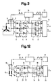
- Fig. 3 ein Blockschaltbild des induktiven Umdrehungssensors gemäss Fig. 1 und 2,
- Fig. 4 eine graphische Darstellung des Spannungsverlaufes zweier Spulen des induktiven Umdrehungssensors,
- Fig.5-8 Impulsdiagramme für die Darstellung der Digitalisierung und Phasendiskrimination der Spulenspannungen gemäss Fig. 4,
- Fig.9+10 Impulsdiagramme für eine Umdrehung bei maximaler Drehzahl des induktiven Umdrehungssensors gemäss Fig. 3,
- Fig. 11 Impulsdiagramme für eine Umdrehung und einen Drittel der maximalen Drehzahl des induktiven Umdrehungssensors gemäss Fig. 3 und
- Fig. 12 ein Blockschaltbild einer zweiten Ausführung eines induktiven Umdrehungssensors.
- 1 shows an axial section of a first embodiment of the inductive rotation sensor according to the invention in a schematic illustration,
- FIG. 2 shows a top view of the inductive rotation sensor according to FIG. 1 in a schematic illustration, FIG.
- 3 shows a block diagram of the inductive rotation sensor according to FIGS. 1 and 2,
- 4 shows a graphical representation of the voltage profile of two coils of the inductive rotation sensor,
- Fig. 5-8 pulse diagrams for the representation of the digitization and phase discrimination of the coil voltages according to Fig. 4,
- 9 + 10 pulse diagrams for one revolution at maximum speed of the inductive revolution sensor according to FIG. 3,
- 11 shows pulse diagrams for one revolution and a third of the maximum speed of the inductive revolution sensor according to FIGS. 3 and
- Fig. 12 is a block diagram of a second embodiment of an inductive rotation sensor.
In den Fig. 1 und 2 sind mit 1 ein lediglich strichpunktiert angedeutetes Gehäuse eines Flügelrad-Durchflussmessers und mit 2 ein Flügelrad bezeichnet. Ein aus elektrisch leitendem Material bestehender Dämpfungskörper 3 ist isoliert mit dem Flügelrad 2 verbunden. Im Gehäuse 1 sind drei, konzentrisch um die Rotationsachse 4 des Flügelrades 2 angeordnete, um 120° versetzte Luftspulen La, Lb, Lc befestigt, mittels welchen ein durch gestrichelte Linien angedeutetes Wechselfeld 5 erzeugt wird. Mit 6 sind durch gestrichelte, konzentrische Linien versinnbildlichte Bahnen eines Wirbelstromes bezeichnet, der durch das Wechselfeld 5 der jeweils betreffenden Luftspule La, Lb oder Lc im Dämpfungskörper 3 hervorgerufen wird.1 and 2, 1 denotes a housing of an impeller flow meter, which is only indicated by dash-dotted lines, and 2 denotes an impeller. A damping
Gemäss Fig. 3 sind die drei Luftspulen La, Lb, Lc über je einen Kondensator 10, 11, 12 parallel geschaltet, so dass drei parallel geschaltete Serieschwingkreise gebildet werden. Je ein Ende der Luftspulen La, Lb, Lc ist über eine Gleichrichteranordnung 13 an einer Auswerteschaltung angeschlossen, die aus einem Digitalisierungsglied 14, einem Phasendiskriminator 15 und einem Schaltwerk 16 besteht. Das Digitalisierungsglied 14 besteht aus einem ersten, zweiten und dritten Schmitt-Trigger 17, 18, 19, deren Eingänge über die Gleichrichteranordnung 13 mit den Enden der Luftspulen La, Lb, Lc in Verbindung stehen. Der Phasendiskriminator 15 weist ein erstes, zweites und drittes D-Flip-Flop 20, 21, 22 auf, deren Dateneingänge D mit invertierenden Ausgängen
Der vorstehend beschriebene induktive Umdrehungssensor arbeitet wie folgt:
Bei Auftreten eines Speisespannungsimpulses werden die aus den Luftspulen La, Lb, Lc und Kondensatoren 10, 11, 12 bestehenden Serieschwingkreise gleichzeitig angeregt, wobei in jeder Luftspule eine gedämpfte cosinusförmige Schwingung entsteht (Zeitpunkt I, Fig. 4-8). Es möge nun angenommen sein, dass sich der Dämpfungskörper 3 im Zeitpunkt der Anregung im Bereiche der einen Luftspule La befindet (Fig. 2), so dass im Dämpfungskörper 3 ein Wirbelstrom 6 induziert wird, dessen Feld die Dämpfung und Resonanzfrequenz des betreffenden Schwingkreises vergrössern. Hierbei tritt an der einen Luftspule La eine Spannung Ua auf, die gegenüber den Spannungen Ub, Uc der beiden anderen Luftspulen Lb, Lc phasenverschoben ist (Fig. 4). Zum Zwecke der Digitalisierung mittels des Digitalisierungsgliedes 14 werden die Spulenspannungen mit Triggerschwellwerten Uein, Uaus verglichen (Fig. 4), wobei über die Gleichrichteranordnung 13 nur die positiven Amplituden der Spulenspannungen übertragen werden, da sonst die Schwingungen bei den negativen Amplituden durch die internen Schutzdioden der Schmitt-Trigger 17, 18, 19 zu stark gedämpft würden. Bei der Digitalisierung tritt am Ausgang
When a supply voltage pulse occurs, the series resonant circuits consisting of the air coils L a , L b , L c and
Bei Weiterdrehen des Flügelrades 2 nach rechts und Eintreffen des nächsten Speisespannungsimpulses SP wird die Luftspule Lb gedämpft, wobei die invertierenden Triggerausgänge
Das Schaltwerk 16 arbeitet derart, dass pro Reihenfolge der Signalzustände, bzw. pro Umdrehung, ein Impuls erzeugt wird, der je nach Drehrichtung an dem einen oder dem anderen Ausgang Ar, Al auftritt. So wird gemäss Beispiel Fig. 9 bei der Reihenfolge 100 010 001 der der Rechtsdrehung zugeordnete Ausgang Ar aktiviert und die Frequenz der hierbei auftretenden Impulse von der Anzeigeeinrichtung als maximale Geschwindigkeit des Flügelrades 2 interpretiert. Es möge nun beispielsweise angenommen sein, dass die Geschwindigkeit des Flügelrades 2 einem Drittel der maximalen Geschwindigkeit entspricht. Hierbei wird während einer Umdrehung entsprechend der gewählten Form des Dämpfungskörpers 3 jede Luftspule mehrere Male gedämpft, wobei die drehrichtungsspezifische Reihenfolge der Signalzustände dreimal so langsam abläuft (Fig. 11, Rechtsdrehung). Auch in diesem Fall wird pro Reihenfolge nur ein Impuls erzeugt, so dass die Frequenz der am zugeordneten Ausgang Ar auftretenden Impulse infolge der langsamer ablaufenden Reihenfolge dreimal kleiner als die Maximalfrequenz ist, so dass die Anzeigeeinrichtung eine dreimal kleinere Geschwindigkeit anzeigt.The
In der Fig. 12 sind mit L![]()
![]()
![]()
![]()
![]()
![]()
![]()
![]()
![]()
![]()
![]()
![]()
![]()
![]()
![]()
![]()
![]()
![]()
![]()
![]()
Der vorstehend beschriebene induktive Umdrehungssensor arbeitet in gleicher Weise wie der anhand der Fig. 1-3 beschriebene. Da jedoch nur zwei Luftspulen L![]()
![]()
![]()
![]()
Claims (7)
- Inductive rotation sensor for impeller wheel throughflow meters, with at least one stationary coil, by means of which an alternating field is generated, with an electrically conductive damping body (3) rotating with the impeller wheel (2) of the throughflow meter past the coil, wherein an eddy current and thereby an opposing field, which reacts on the alternating field of the coil, is generated in the damping body (3) by the alternating field of the coil, and with an evaluating circuit processing the result of the reaction of the damping body (3), characterised thereby,- that three stationary coils (La, Lb, Lc) are provided and arranged displaced through 120° concentrically about the rotational axis (4) of the impeller wheel (2),- that the three coils (La, Lb, Lc) are connected in parallel each by way of a respective capacitor (10, 11, 12), wherein the one ends of the three coils (La, Lb, Lc) are at ground and the other ends are connected with the evaluating circuit and by way of the capacitors (10, 11, 12) with an equipment (24) for the generation of supply voltage pulses (SP), which is connected at the input to a clock pulse generator (23),- that the coils (La, Lb, Lc) are as per se known fed intermittently, wherein the frequency of the supply voltage pulses (SP) corresponds to a multiple of the maximum rotational speed of the impeller wheel (2) and- wherein the respective frequency of the voltage of that coil is increased, past which the damping body (3) is rotating, and- that a digitalising member (14), which produces pulse sequences corresponding to the voltage courses of the coils (La, Lb, Lc), is provided in the evaluating circuit, wherein the pulse sequence of the respectively damped coil has a higher frequency than the pulse sequences of the undamped coils and wherein the rotational direction and the rotational speed of the impeller wheel (2) is ascertainable from the successive changes in the position of the pulse of the damped coil relative to the pulses of the undamped coils during one rotation.
- Inductive rotation sensor for impeller wheel throughflow meters, with at least one stationary coil, by means of which an alternating field is generated, with an electrically conductive damping body rotating with the impeller wheel of the throughflow meter past the coil, wherein an eddy current and thereby an opposing field, which reacts on the alternating field of the coil, is generated in the damping body by the alternating field of the coil, and with an evaluating circuit processing the result of the reaction of the damping body, characterised thereby- that two stationary coils (La′, Lb′) are provided and arranged symmetrically to the rotational axis of the impeller wheel,- that the two coils (La′, Lb′) are connected in parallel each by way of a respective capacitor (30, 31), wherein the one ends of the two coils (La′, Lb′) are at ground and the other ends are connected with the evaluating circuit and by way of the capacitors (30, 31) with an equipment (41) for the generation of supply voltage pulses (SP), which is connected at the input to a clock pulse generator (40),- that the coils (La′, Lb′) are per se known fed intermittently, wherein the frequency of the supply voltage pulses (SP) corresponds to a multiple of the maximum rotational speed of the impeller wheel and- wherein the respective frequency of the voltage of that coil is increased, past which the damping body is rotating, and- that a digitalising member (33) which produces pulse sequences corresponding to the voltage courses of the coils (La′, Lb′), is provided in the evaluating circuit, wherein the pulse sequence of the respectively damped coil has a higher frequency than the pulse sequences of the undamped coil and wherein the rotational speed of the impeller wheel is ascertainable from the changes in the position of the pulse of the damped coil relative to the pulses of the undamped coil during one rotation.
- Inductive rotation sensor according to the claims 1 and 2, characterised thereby, that the coil ends are connected to the evaluating circuit by way of a rectifier arrangement (13, 32) so that exclusively the positive amplitudes of the coil voltages are transmitted.
- Inductive rotation sensor according to claim 3, characterised thereby, that the evaluating circuit has a phase discriminator (15, 34) and a switching mechanism (16, 35), which are connected in series with the digitalising member (14, 33).
- Inductive rotation sensor according to claim 1 in conjunction with claim 4, characterised thereby,- that the digitalising member (14) consists of a first, a second and a third Schmitt trigger stage (17, 18, 19), the inputs of which stand in connection with the ends of the coils (La, Lb, Lc) by way of the rectifier arrangement (13),- that the phase discriminator (15) has a first,a second and a third D-flip-flop (20, 21, 22), the data inputs (D) of which are connected with inverting outputs (
S a,S b,S c) of the Schmitt trigger stages (17, 18, 19), and the pulse input (C) of the first D-flip-flop (20) is connected to the inverting output (S b) of the second Schmitt trigger stage (18), the pulse input (C) of the second D-flip-flop (21) is connected to the inverting output (S c) of the third Schmitt trigger stage (19) and the pulse input (C) of the third D-flip-flop (22) is connected to the inverting output (S a) of the first Schmitt trigger stage (17), and- that the switching mechanism (16) is connected at the input with the outputs (Qa, Qb, Qc) of the D-flip-flops (20, 21, 22) and with the clock pulse generator (23) and has two outputs (Ar, Al),- wherein the switching mechanism (16) generates one pulse for each rotation of the impeller wheel (2) and the generated pulses appear at the one output (Ar) in the case of right-hand rotation and at the other output (Al) in the case of left-hand rotation. - Inductive rotation sensor according to claim 2, in conjunction with claim 4, characterised thereby,- that the digitalising member (33) consists of a first and a second Schmitt trigger stage (36, 37) the inputs of which stand in connection with the ends of the coils (La′, Lb′) by way of the rectifier arrangement (32),- that the phase discriminator (34) has a first and a second D-flip-flop (38, 39), the data inputs (D) of which are connected with inverting outputs (
S a,S b) of the Schmitt trigger stages (36, 37), and the pulse input (C) of the first D-flip-flop (38) is connected to the inverting output (S b) of the second Schmitt trigger stage (37) as well as the pulse input (C) of the second D-flip-flop (3a) is connected to the inverting output (S a) of the first Schmitt trigger stage (36), and- that the switching mechanism (35) is connected at the input with the outputs (Qa, Qb) of the D-flip-flops (38, 39) and with the clock pulse generator (40) and has one output (A),- wherein the switching mechanism (35) generates one pulse for each rotation of the impeller wheel and the generated pulses appear at the output (A). - Inductive rotation sensor according to the claims 1 and 2, characterised thereby, that the coils (La, Lb, Lc or La′, Lb′) are air-cored coils.
Priority Applications (1)
| Application Number | Priority Date | Filing Date | Title |
|---|---|---|---|
| AT89115004T ATE85425T1 (en) | 1988-10-27 | 1989-08-14 | INDUCTIVE RPM SENSOR FOR IMPELLER FLOWMETER. |
Applications Claiming Priority (2)
| Application Number | Priority Date | Filing Date | Title |
|---|---|---|---|
| CH401788 | 1988-10-27 | ||
| CH4017/88 | 1988-10-27 |
Publications (2)
| Publication Number | Publication Date |
|---|---|
| EP0370174A1 EP0370174A1 (en) | 1990-05-30 |
| EP0370174B1 true EP0370174B1 (en) | 1993-02-03 |
Family
ID=4268259
Family Applications (1)
| Application Number | Title | Priority Date | Filing Date |
|---|---|---|---|
| EP89115004A Expired - Lifetime EP0370174B1 (en) | 1988-10-27 | 1989-08-14 | Inductive rotation sensor for a vane-type flow meter |
Country Status (4)
| Country | Link |
|---|---|
| EP (1) | EP0370174B1 (en) |
| AT (1) | ATE85425T1 (en) |
| DE (1) | DE58903449D1 (en) |
| DK (1) | DK529889A (en) |
Cited By (2)
| Publication number | Priority date | Publication date | Assignee | Title |
|---|---|---|---|---|
| DE19538163C1 (en) * | 1995-10-13 | 1997-03-27 | Wehrle E Gmbh | Rotation rate and rotation direction detection method e.g. for water meter |
| US6850054B2 (en) | 2000-08-09 | 2005-02-01 | Elster Messtechnik Gmbh | Device and a method for non-contacting sensing of the rotational state of a rotor |
Families Citing this family (9)
| Publication number | Priority date | Publication date | Assignee | Title |
|---|---|---|---|---|
| FR2664973B1 (en) * | 1990-07-20 | 1992-10-23 | Schlumberger Ind Sa | DEVICE FOR DETECTING THE ROTATION OF A ROTATING ELEMENT SUCH AS THE TURBINE OF A WATER METER. |
| DE4446918A1 (en) * | 1994-12-28 | 1996-07-04 | Spanner Pollux Gmbh | Inductive sensor for measuring the speed or direction of rotation of a shaft |
| DE29906448U1 (en) * | 1999-04-12 | 1999-08-12 | Alfons Haar Maschinenbau Gmbh & Co, 22547 Hamburg | Sensor for the contactless measurement of the rotation of a rotor in a liquid flow meter |
| DE10352251B4 (en) * | 2003-11-08 | 2019-10-24 | Elster Messtechnik Gmbh | Device for guiding and positioning electrical components |
| GB2429118A (en) * | 2005-07-26 | 2007-02-14 | Sensor Technology Ltd | Rotary signal coupler having inductive and capacitive elements in series |
| AT510531A1 (en) * | 2010-10-05 | 2012-04-15 | Kral Ag | FLOW MEASURING DEVICE |
| DE202013001852U1 (en) * | 2013-02-27 | 2014-02-28 | Christian Gradischnik | Device for detecting a flow |
| DE102013215604A1 (en) * | 2013-08-07 | 2015-02-12 | BSH Bosch und Siemens Hausgeräte GmbH | Flow meter, rotor and water-conducting household appliance |
| CN107747984B (en) * | 2017-10-27 | 2019-11-19 | 深圳友讯达科技股份有限公司 | Reference voltage modification method and device |
Family Cites Families (6)
| Publication number | Priority date | Publication date | Assignee | Title |
|---|---|---|---|---|
| US3996800A (en) * | 1974-05-17 | 1976-12-14 | Combustion Engineering, Inc. | Turbine meter |
| JPS54141166A (en) * | 1978-04-25 | 1979-11-02 | Toukiyouto | Water meter |
| DE2943184A1 (en) * | 1979-10-25 | 1981-05-07 | AOA Apparatebau Gauting GmbH, 8035 Gauting | Driven wheel fluid flow meter - has inductive speed measurement consisting of sensors and elements of different magnetic resistance |
| EP0029336A1 (en) * | 1979-11-15 | 1981-05-27 | Britax Vega Limited | Improvements in or relating to flowmeters |
| DE3611862A1 (en) * | 1986-04-09 | 1987-10-15 | Steudler Gmbh & Co Kg A | INDUCTIVE PROXIMITY SENSOR |
| DE3642678A1 (en) * | 1986-12-13 | 1988-06-16 | Bosch Gmbh Robert | MEASURING DEVICE FOR TURNING ANGLE AND / OR TURNING SPEED |
-
1989
- 1989-08-14 AT AT89115004T patent/ATE85425T1/en not_active IP Right Cessation
- 1989-08-14 EP EP89115004A patent/EP0370174B1/en not_active Expired - Lifetime
- 1989-08-14 DE DE8989115004T patent/DE58903449D1/en not_active Expired - Fee Related
- 1989-10-25 DK DK529889A patent/DK529889A/en not_active Application Discontinuation
Cited By (2)
| Publication number | Priority date | Publication date | Assignee | Title |
|---|---|---|---|---|
| DE19538163C1 (en) * | 1995-10-13 | 1997-03-27 | Wehrle E Gmbh | Rotation rate and rotation direction detection method e.g. for water meter |
| US6850054B2 (en) | 2000-08-09 | 2005-02-01 | Elster Messtechnik Gmbh | Device and a method for non-contacting sensing of the rotational state of a rotor |
Also Published As
| Publication number | Publication date |
|---|---|
| EP0370174A1 (en) | 1990-05-30 |
| DK529889A (en) | 1990-04-28 |
| DK529889D0 (en) | 1989-10-25 |
| ATE85425T1 (en) | 1993-02-15 |
| DE58903449D1 (en) | 1993-03-18 |
Similar Documents
| Publication | Publication Date | Title |
|---|---|---|
| EP0179384B1 (en) | Interfering fields-insensitive proximity switch | |
| DE2805935A1 (en) | DETECTOR DEVICE | |
| EP0370174B1 (en) | Inductive rotation sensor for a vane-type flow meter | |
| DE602004010486T2 (en) | Inductive proximity sensor | |
| EP0132745B1 (en) | Device for measuring direct currents | |
| DE3519215C2 (en) | ||
| DE3611862A1 (en) | INDUCTIVE PROXIMITY SENSOR | |
| EP0311128B1 (en) | Method and device for exciting a resonating circuit | |
| DE2605764A1 (en) | FREQUENCY CHANGING DEVICE, IN PARTICULAR FOR USE IN A FLOW METER | |
| DE3213602C2 (en) | ||
| WO1989003616A1 (en) | Inductive proximity detector | |
| DE69805871T2 (en) | Length measuring device using a magnetostrictive delay line | |
| DE4137695C2 (en) | Sensor arrangement for determining the state of motion of a rotor | |
| DE3133330C2 (en) | Magnetic-inductive flow meter | |
| DE3017202C2 (en) | Device for determining the speed of a rotatable component or the frequency of a linearly vibrating component made of magnetically permeable material | |
| EP0045509B1 (en) | Means for the determination of the intensity of magnetic fields, e.g. earth fields | |
| DE3241222A1 (en) | Device for measuring the rotation speed and, if applicable, the rotation direction of an impeller wheel of an impeller wheel flowmeter for preferably electrolytic fluids | |
| EP1007909A1 (en) | Magnetic resonance sensor | |
| DE2831598C2 (en) | Device for distance and speed measurement | |
| DE2837014C3 (en) | Arrangement for measuring the distance between the change in distance and the speed of change in distance between two bodies which can be moved relative to one another on a predetermined path of movement | |
| DE2931329A1 (en) | Shaft rotation direction determn. for vehicle direction determn. - by using magnetic sensor and asymmetric magnet producing direction dependent pulsed signal duty cycle | |
| EP0697769A1 (en) | Magnetic proximity detector | |
| EP0080055A2 (en) | Electromagnetic displacement sensor | |
| EP0059770B1 (en) | Device for recording a magnetic field | |
| EP3975211B1 (en) | Unification of resolver and inductive rotor supply in one magnetic circuit |
Legal Events
| Date | Code | Title | Description |
|---|---|---|---|
| PUAI | Public reference made under article 153(3) epc to a published international application that has entered the european phase |
Free format text: ORIGINAL CODE: 0009012 |
|
| AK | Designated contracting states |
Kind code of ref document: A1 Designated state(s): AT BE CH DE FR GB IT LI NL SE |
|
| 17P | Request for examination filed |
Effective date: 19900927 |
|
| 17Q | First examination report despatched |
Effective date: 19920213 |
|
| GRAA | (expected) grant |
Free format text: ORIGINAL CODE: 0009210 |
|
| AK | Designated contracting states |
Kind code of ref document: B1 Designated state(s): AT BE CH DE FR GB IT LI NL SE |
|
| REF | Corresponds to: |
Ref document number: 85425 Country of ref document: AT Date of ref document: 19930215 Kind code of ref document: T |
|
| REF | Corresponds to: |
Ref document number: 58903449 Country of ref document: DE Date of ref document: 19930318 |
|
| ET | Fr: translation filed | ||
| GBT | Gb: translation of ep patent filed (gb section 77(6)(a)/1977) |
Effective date: 19930218 |
|
| ITF | It: translation for a ep patent filed | ||
| PLBE | No opposition filed within time limit |
Free format text: ORIGINAL CODE: 0009261 |
|
| STAA | Information on the status of an ep patent application or granted ep patent |
Free format text: STATUS: NO OPPOSITION FILED WITHIN TIME LIMIT |
|
| 26N | No opposition filed | ||
| PGFP | Annual fee paid to national office [announced via postgrant information from national office to epo] |
Ref country code: GB Payment date: 19940712 Year of fee payment: 6 |
|
| EAL | Se: european patent in force in sweden |
Ref document number: 89115004.7 |
|
| PGFP | Annual fee paid to national office [announced via postgrant information from national office to epo] |
Ref country code: BE Payment date: 19950630 Year of fee payment: 7 |
|
| PGFP | Annual fee paid to national office [announced via postgrant information from national office to epo] |
Ref country code: AT Payment date: 19950727 Year of fee payment: 7 |
|
| PG25 | Lapsed in a contracting state [announced via postgrant information from national office to epo] |
Ref country code: GB Effective date: 19950814 |
|
| GBPC | Gb: european patent ceased through non-payment of renewal fee |
Effective date: 19950814 |
|
| PG25 | Lapsed in a contracting state [announced via postgrant information from national office to epo] |
Ref country code: AT Effective date: 19960814 |
|
| PG25 | Lapsed in a contracting state [announced via postgrant information from national office to epo] |
Ref country code: BE Effective date: 19960831 |
|
| BERE | Be: lapsed |
Owner name: GAS- & WASSERMESSERFABRIK A.G. GAS Effective date: 19960831 |
|
| PGFP | Annual fee paid to national office [announced via postgrant information from national office to epo] |
Ref country code: CH Payment date: 19981120 Year of fee payment: 10 |
|
| PG25 | Lapsed in a contracting state [announced via postgrant information from national office to epo] |
Ref country code: LI Free format text: LAPSE BECAUSE OF NON-PAYMENT OF DUE FEES Effective date: 19990831 Ref country code: CH Free format text: LAPSE BECAUSE OF NON-PAYMENT OF DUE FEES Effective date: 19990831 |
|
| REG | Reference to a national code |
Ref country code: CH Ref legal event code: PL |
|
| PGFP | Annual fee paid to national office [announced via postgrant information from national office to epo] |
Ref country code: NL Payment date: 20000725 Year of fee payment: 12 |
|
| PGFP | Annual fee paid to national office [announced via postgrant information from national office to epo] |
Ref country code: SE Payment date: 20000726 Year of fee payment: 12 |
|
| PGFP | Annual fee paid to national office [announced via postgrant information from national office to epo] |
Ref country code: FR Payment date: 20000801 Year of fee payment: 12 |
|
| PGFP | Annual fee paid to national office [announced via postgrant information from national office to epo] |
Ref country code: DE Payment date: 20000802 Year of fee payment: 12 |
|
| PG25 | Lapsed in a contracting state [announced via postgrant information from national office to epo] |
Ref country code: SE Free format text: LAPSE BECAUSE OF NON-PAYMENT OF DUE FEES Effective date: 20010815 |
|
| PG25 | Lapsed in a contracting state [announced via postgrant information from national office to epo] |
Ref country code: NL Free format text: LAPSE BECAUSE OF NON-PAYMENT OF DUE FEES Effective date: 20020301 |
|
| EUG | Se: european patent has lapsed |
Ref document number: 89115004.7 |
|
| PG25 | Lapsed in a contracting state [announced via postgrant information from national office to epo] |
Ref country code: FR Free format text: LAPSE BECAUSE OF NON-PAYMENT OF DUE FEES Effective date: 20020430 |
|
| NLV4 | Nl: lapsed or anulled due to non-payment of the annual fee |
Effective date: 20020301 |
|
| PG25 | Lapsed in a contracting state [announced via postgrant information from national office to epo] |
Ref country code: DE Free format text: LAPSE BECAUSE OF NON-PAYMENT OF DUE FEES Effective date: 20020501 |
|
| REG | Reference to a national code |
Ref country code: FR Ref legal event code: ST |
|
| PG25 | Lapsed in a contracting state [announced via postgrant information from national office to epo] |
Ref country code: IT Free format text: LAPSE BECAUSE OF NON-PAYMENT OF DUE FEES;WARNING: LAPSES OF ITALIAN PATENTS WITH EFFECTIVE DATE BEFORE 2007 MAY HAVE OCCURRED AT ANY TIME BEFORE 2007. THE CORRECT EFFECTIVE DATE MAY BE DIFFERENT FROM THE ONE RECORDED. Effective date: 20050814 |