EP0290620B1 - Apparatus for observation using charged particle beams and method of surface observation using charged particle beams - Google Patents
Apparatus for observation using charged particle beams and method of surface observation using charged particle beams Download PDFInfo
- Publication number
- EP0290620B1 EP0290620B1 EP87907527A EP87907527A EP0290620B1 EP 0290620 B1 EP0290620 B1 EP 0290620B1 EP 87907527 A EP87907527 A EP 87907527A EP 87907527 A EP87907527 A EP 87907527A EP 0290620 B1 EP0290620 B1 EP 0290620B1
- Authority
- EP
- European Patent Office
- Prior art keywords
- specimen
- magnetic field
- charged particles
- emitted
- electrons
- Prior art date
- Legal status (The legal status is an assumption and is not a legal conclusion. Google has not performed a legal analysis and makes no representation as to the accuracy of the status listed.)
- Expired - Lifetime
Links
Images


Classifications
-
- H—ELECTRICITY
- H01—ELECTRIC ELEMENTS
- H01J—ELECTRIC DISCHARGE TUBES OR DISCHARGE LAMPS
- H01J37/00—Discharge tubes with provision for introducing objects or material to be exposed to the discharge, e.g. for the purpose of examination or processing thereof
- H01J37/26—Electron or ion microscopes; Electron or ion diffraction tubes
- H01J37/28—Electron or ion microscopes; Electron or ion diffraction tubes with scanning beams
-
- H—ELECTRICITY
- H01—ELECTRIC ELEMENTS
- H01J—ELECTRIC DISCHARGE TUBES OR DISCHARGE LAMPS
- H01J2237/00—Discharge tubes exposing object to beam, e.g. for analysis treatment, etching, imaging
- H01J2237/26—Electron or ion microscopes
- H01J2237/28—Scanning microscopes
- H01J2237/2809—Scanning microscopes characterised by the imaging problems involved
- H01J2237/281—Bottom of trenches or holes
Definitions
- the present invention relates to an apparatus adapted for observing an image composed of secondary electrons generated in a recessed portion when the charged particle beam is focused on a specimen having recessed portions, such as through holes formed in the processes carried out in an LSI production line, and a method for observing a surface by a charged particle beam.
- Fig. 1 shows a column of an apparatus for observing a surface utilizing a charged particle observation reported by Y. Furuya, T. Ohtaka, S. Yamada, H. Mori, M. Yamada, T. Watanabe and K. Ishikawa in "Modes S-6000 Field Emission CD Measurement SEM", the 93th study reference disclosed at the 132th committee held on Japan Society for the Promotion of.Science (November 8-9, 1985), pp. 1.
- Electrons 1 (to be referred to as "the primary electrons" hereinafter in this specification) emitted from a cathode 2 are accelerated by a first anode 3 and a second anode 4 and are focused on the upper surface of a specimen 8 through a condenser lens 5 and an objective lens 6.
- the focusing point on the surface of the specimen 8 at which are focused the primary electrons 1 is controlled by a deflection coil 7.
- Secondary electrons 9 produced in response to the impingement of the primary electrons 1 on the surface of the specimen 8 pass through the objective lens 6 and are detected by a secondary electron detector 10.
- the secondary electron image on the surface of the specimen 8 can be observed by detecting the secondary electrons 9 by the secondary electron detector 10 while the primary electrons 1 are caused to scan the surface of the specimen by using the deflection coil 7.
- Fig. 2 the trajectory of the secondary electrons emitted from a cylindrical through hole 1 ⁇ m in depth and 0.5 ⁇ m in diameter are shown in Fig. 2.
- An insulating layer 12 is formed on the surface of a substrate 11 and the specimen 8 shown in Fig. 1 is composed of the substrate 11 and the insulating layer 12.
- the insulating layer 12 is formed with a through hole 0.5 ⁇ m in diameter (D) and 1 ⁇ m in depth (T).
- Reference numeral 13 represents the central axis of the through hole; 14, the trajectory of the secondary electron emitted at an angle of 5° with respect to the central axis 13 from the center of the through hole; 15, the trajectory of the secondary electron emitted at an angle of 10° with respect to the central axis 13 from the center of the through hole; and 16, the trajectories of the secondary electrons emitted from the center of the through hole at an angle between 15° and 85° with respect to the central axis 13.
- the energy of the secondary electrons 14-16 is 5 eV.
- In the through hole there exists magnetic flux of 1 x 10⁴ A/m corresponding to the leakage flux of the objective lens 6 in parallel with the axis 13.
- the magnetic field applied perpendicularly to the surface of the specimen 8 is of the order of about 1 x 10⁴ A/m.
- the magnetic field applied to the specimen 8 must be increased by about 100 times so that the excitation current of the objective lens 7 must be increased also of the order of about 100 times.
- reference numeral 1 represents the trajectory of the primary electrons prior to the increase of the excitation current for the objective lens 6; 17, a point at which the primary electrons 1 converge; 18, a trajectory of the primary electrons after the excitation current for the objective lens 6 is increased; and 19, the point of convergence or focusing point of the primary electrons when the excitation current is increased.
- the focusing point 17 is at the upper surface of the specimen 8, but when the excitation current for the objective lens 6 is increased, the focusing point 19 of the primary electrons shifts upwardly of the specimen 8. As a result, the diameter of the primary electron beam impinged on the surface of the specimen 8 is increased so that there is the problem that the secondary electron image to be observed becomes out of focus.
- JP-A-60-130044 discloses a scanning type electron microscope and intends to improve secondary electron collecting efficiency and the signal-to-noise ratio.
- An electromagnetic lens is provided in a space surrounded by the upper pole piece of an objective lens for preventing collisions of the secondary electrons with the inner wall of the upper pole piece.
- Said known microscope is not intended for observing a surface with a recess or for observing the inner wall or bottom surface of the recess. Therefore, there is no technical idea of a strong magnetic field on the surface of the specimen necessary in order to emit the secondary electrons out of a recess in the surface of the specimen.
- EP-A-0 138 610 relates to an electron detector for analyzing the energies of received secondary electrons emitted by a target object in response to electron beam bombardment.
- One of the object of the present invention is, therefore, to provide an apparatus for observing a surface utilizing a charged particle beam which can permit the observation of a secondary electron image emitted from the bottom of a recess such as a through hole formed in the surface of a specimen.
- Another of the present invention is to provide a method for observing a surface by a charged particle beam in order to obtain a sharp secondary electron image on the surface of a specimen.
- a through hole is substantially in the form of a cube or a cylinder.
- a configuration which is a square in the case of a through hole formed by a cube or a circle in the case of a through hole formed by a cylinder.
- Dt the diameter of the inscribed circle for the above configuration
- Dt the condition under which a secondary electron is emitted from the bottom of the through hole at an angle ⁇ with respect to the central axis thereof
- Fig. 5 shows a column of a preferred embodiment of a charged particle beam observation apparatus in accordance with the present invention. With this apparatus, the through holes having a diameter of the order of 0.5 ⁇ m can be observed.
- the primary electrons emitted from a cathode 21 are accelerated by anode 22 and focused on the surface of a specimen 8 through a condenser lens 23, a focusing lens 24, and a magnetic field produced by an exciting device 25 which can apply a strong magnetic field perpendicularly to the surface of the specimen 8.
- the focal point on the surface of the specimen 8 can be controlled by a deflection coil 26.
- the secondary electrons 28 emitted from the surface of the specimen 8 pass through both the exciting device 25 and the focusing lens 24 and are detected by a secondary electron detector 27.
- the above-described apparatus is substantially similar to construction of the conventional apparatus utilizing a charged particle beam except that the present invention provides the exciting device 25, so the secondary electron image of the specimen 8 can be observed by detecting the secondary electrons by the secondary electron detector 27 while scanning the surface of the specimen 8 by the primary electrons 20.
- Fig. 6 shows an example of the construction of the exciting device.
- the exciting device 25 comprises a magnetic circuit 29 and a coil 30.
- Reference numeral 31 denotes an extracting electrode.
- Reference numeral 32 indicates lines of magnetic force produced by the exciting device 25; and 28 indicates the secondary electrons emitted from the specimen 8.
- the specimen 8 is formed with a through hole 33 of the size of 0.5 ⁇ m.
- the radius of the coil 30 is about 1 mm and the current of 2 x 10⁵ AT flows through the coil 30.
- the extracting electrode 31 is in the form of a mesh and is applied with a voltage of 1 kV.
- each secondary electron 28 emitted from the bottom of the through hole 33 moves through the through hole 33 while making a spiral motion with a Larmor radius of about 0.1 ⁇ m, and most of all the secondary electrons 28 go out of the through hole 33.
- the secondary electron 28 which comes out of the through hole 33 moves spirally in the direction perpendicular to the surface of the specimen 8 and is extracted to the exterior of the exciting device 25 due to the extracting electric field produced by the extracting electrode 31.
- most of all the secondary electrons 28 emitted from the bottom of the through hole 33 can reach the secondary electron detector 27, so that it is possible to observe the secondary electron image at the bottom of the through hole.
- the exciting device 25 is disposed in the vicinity of the specimen and the magnetic field which satisfies the condition expressed by Eq. (4) is applied to the specimen 8 so that most of all the secondary electrons emitted from the bottom of the through hole can be extracted from it. As a result, it becomes possible to observe the secondary electron image at the bottom of the through hole.
- each secondary electron 28 in spiral motion goes out of the through hole 33.
- the secondary electrons 28A emitted from the peripheral portion of the bottom of the through hole impinge on the side wall of the through hole, so that they cannot go out of the through hole. Therefore, the image viewed through a scanning electron microscope as the image of the bottom of the through hole has a dark peripheral portion 34 of a width l as shown in Fig. 8.
- the width l is substantially equal to the Lamore radius of the secondary electron. It follows, therefore, that when the magnetic field produced by the exciting device is increased, the width l can be reduced.
- Another method for observing the whole surface of the bottom of through hole is to determine the magnitude of the magnetic field in such a way that the trajectories 28B of the secondary electrons become great arcs as shown in Fig. 9.
- the number of the secondary electrons emitted from the bottom of the through hole 33 and extracted out of the through hole 33 becomes smaller than that of the secondary electrons shown in Fig. 7, but it becomes possible to observe the whole bottom surface of the through hole.
- Fig. 10 shows a second preferred embodiment of an apparatus for observing a surface utilizing a charged particle beam in accordance with the present invention. Only an exciting device 35 and a specimen 8 are shown in Fig. 10 and the remaining component parts are substantially same as those shown in Fig. 1.
- the exciting device 35 comprises a magnetic path 36 and a coil 37.
- Reference numeral 38 denotes an extracting electrode.
- a specimen stand 39 is made of a magnetic material and is vertically movable by a driving mechanism (not shown). When the current flows through the coil 37, the lines of magnetic force 40 are produced in the direction perpendicular to the specimen 8 between the magnetic path 36 and the specimen stand 39.
- the specimen stand 39 is moved downwardly as shown in Fig. 11 and the specimen 8 is moved into or out of the space defined between the magnetic circuit 40 and the specimen stand 39.
- the motion of the secondary electron emitted from the through hole is substantially similar to that produced by the exciting device shown in Fig. 6.
- the specimen 8 is interposed between the specimen stand 39 made of magnetic material and the magnetic path 36 so that the magnetic field can be applied to a wide area of the specimen 8 in the direction perpendicular thereto. As a result, it becomes possible to observe the through hole in wide region of the specimen 8.
- Fig. 12A shows the results obtained by the electron trajectory tracing carried out to the trajectories of the electrons emitted from a specimen placed in a rotationally symmetrical magnetic field in accordance with the electron trajectory tracing program described in "Electron Ray Tracing with High Accuracy", K. Saito, T. Okubo, K. Tamamoto, Y. Uno and M. Kondo, J. Vac. Sci. Technol. A4 , (4), 1913-1917 (1956).
- Reference numeral 8 represents a specimen; 41, the central axis of the rotationally symmetrical magnetic field; and 42 and 43, trajectories of the electrons, respectively, emitted from the specimen 8.
- Same reference numerals 42 and 43 are used to designate the electrons moving along the trajectories 42 and 43.
- the electrons 42 and 43 rotate about the axis 41 under the influence of the magnetic field, but in Fig. 12A, the electron trajectories are shown as viewed from a coordinate system revolving in unison with the electrons 42 and 43.
- Reference numerals 44 and 45 indicate the points of intersection between the electrons 42 and 43. All the electrons emitted from the upper surface of the specimen 8 at very small angles with respect to the center axis 41 pass through these points.
- the points of intersection 44 and 45 are referred to as "converging points" of electrons hereinafter in this specification.
- the energy of the electrons 42 and 43 is of the order of about 5 keV.
- Fig. 12B shows the distribution of the magnetic field along the center axis 41.
- the magnetic field component Hz in the direction of the center axis 41 is plotted along the abscissa, while the positions on the center axis with respect to the upper reference surface of the specimen 8 are plotted along the ordinate as Z.
- a magnetic field of about 1.6 x 10⁶ AT/m is applied to the specimen 8.
- the distribution of this magnetic field corresponds, for instance, to the distribution of the magnetic field along the optic axis of the objective lens 6 when the excitation current flowing through the objective lens 6 is increased in accordance with the conventional apparatus as shown in Fig. 1.
- the electrons 42 and 43 emitted from the specimen 8 pass move upwardly of the specimen through the converging points 44 and 45 .
- the reciprocity law of the electron trajectory (refer to "DENSHI KOGAKU (Electron Optics)", published by Kyoritsu Publication KK, by K. Ura, in 1979, page 70)
- due to reversing the direction of the magnetic field without changing its magnitude for instance, in the conventional apparatus as shown in Fig. 1, the excitation current of the objective lens 6 is reversed
- the present invention utilizes the above-described phenomenon and comprises an exciting device capable of applying a strong magnetic field on the surface of a specimen and a focusing lens for controlling the position of the primary electron beam, the focusing lens being disposed at a position in such a way that when converging points of electrons, which are imaginarily emitted from the surface of the specimen and each of which has the same energy as the primary electron, exist between the focusing lens and the specimen, then the primary electrons are converged at the position of converging point by using this focusing lens.
- Fig. 13 is a sectional view showing a third preferred embodiment of an apparatus for observing a surface utilizing a charged particle beam in accordance with the present invention.
- the primary electrons 46 which emitted from a cathode 47 are accelerated by an anode 48.
- the focusing lens 50 is a magnetic lens.
- the focusing lens 50 and the exciting device 51 are combined to act as an objective lens. More particularly, the function of the conventional objective lens is divided into the application of a magnetic field and the focusing, so that it becomes possible to focus in the strong magnetic field.
- the third embodiment of the present invention is substantially similar in construction to the conventional apparatus.
- the focal point of the primary electrons 46 on the surface of the substrate 8 is controlled by a deflection coil 49 and the secondary electrons 53 emitted from the surface of the specimen 8 are detected by a secondary electron detector 52, so that it becomes possible to observe the specimen 8.
- FIG. 14 shows the trajectories of imaginary emitted electrons each having the same energy of each primary electron 47 emitted from the upper surface of the specimen 8.
- a focusing lens 50 comprises a magnetic path 54 and a coil 55.
- the exciting device 51 comprises a magnetic path 56 and a coil 57.
- a specimen 8 is mounted on the bottom of the magnetic path 56.
- Reference numeral 58 and 59 represent the electrons emitted from the upper surface of the specimen 8 each having the same energy as that of the primary electron.
- 60 and 61 are converging points of the electrons 58 and 59.
- the positions of the converging points 60 and 61 are uniquely determined by the magnitude of the current flowing through the coil 57 and the energies of the electrons 58 and 59.
- Fig. 15 shows the relationship between the energies of the electrons 58 and 59 and the position Z0 of the converging point 60 furthermost from the specimen obtained by the electron trajectory tracing program disclosed in the above mentioned reference report by K. Saito et al.
- the converging point 60 is measured from the upper surface of the specimen 8.
- the current flowing through the coil 57 is about 10 kAT.
- the position of the converging point 60 has a finite value.
- the energies of the electrons 58 and 59 are lower than about 11 keV (corresponding to the characteristic curve A in Fig. 15)
- two converging points are defined as shown in Fig. 14.
- the energies of the electrons 58 and 59 exceed about 11 keV (corresponding to the characteristic curve B in Fig. 15)
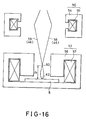
- only one converging point 62 is defined as shown in Fig. 16.
- the focusing lens 50 is disposed in such a way that the undersurface of the magnetic path 54 is spaced apart upwardly from the upper surface of the specimen 8 by 20 mm.
- the converging points 60 are defined between the specimen 8 and the focusing lens 50. Therefore, in a method to be described hereinafter, the primary electrons 46 with the energy range between 5 and 25 keV except the magnitudes closer to about 11 keV can be focused upon the upper surface of the specimen 8.
- the primary electrons pass the converging points 60 and 61 in the order named and an focused on the position 62 on the surface of the specimen 8.
- Fig. 19 shows a sectional view of a coil of constructing an exciting device.
- the coil 63 is made by winding an insulated copper pipe 64 whose exterior surface is coated with an epoxy resin.
- the tube 64 has an outer square cross section with the sides of 5 mm and an inner square cross section with the sides of 3 mm.
- the cooling water at a pressure of 2 kg/cm2 is injected into the pipe through a inlet port 64A.
- the water flows through the pipe 64 and is discharged from a discharge port 64B.
- the heat generated from the pipe is dissipated to the exterior of the pipe through the water flowing the rethrough, so that the temperature rise of the coil can be reduced.
- Fig. 20 shows the dependence of the coil temperature on the excitation current experimentally obtained by using the above-described coil.
- the excitation current is 16000 AT
- the temperature of the coil of the objective lens in the conventional apparatus rises higher than 100°C
- the temperature of the coil in accordance with the present invention is 70°C. Therefore, in the apparatus for observing a surface utilizing a charged particle beam in accordance with the present invention, accidents such as a breakdown of the insulator and the like can be prevented, so that a stable operation of the apparatus can be ensured.
- a cooling medium which is caused to flow through the coil cannot be used only water, but also liquefied nitrogen.
- the cross sectional configuration of the pipe is not limited to a square and may be rectangular, circular or the like.
- the pipe may be made of aluminum or any other suitable conductor instead of copper and it suffices that the surface of a pipe is insulated.
- Fig. 21 shows another embodiment of the exciting device in accordance with the present invention.
- the exciting device 65 uses a superconducting pipe. More particularly, a superconducting coil 67 is disposed within a thermal-insulating container 66 and is cooled by a cooling medium 68 such as liquefied nitrogen.
- Reference numeral 69 represents an extracting electrode.
- Fig. 22 shows a further embodiment of the exciting device in accordance with the present invention.
- the exciting device 72 comprises a thermal-insulating container 73, a superconducting coil 74, a casing 75 which is made of a superconductive material as niobium alloy and encloses the superconducting coil 74 and a cooling medium 76.
- the casing 75 is formed with an air gap 75A only at a position in opposition to the specimen 8.
- the magnetic field produced by the superconducting coil 74 leaks to the exterior of the casing 75 only through the air gap 75A, so that the strong magnetic field can be applied to a narrow portion in the vicinity of the specimen.
- Reference numeral 77 designates lines of magnetic force; and 78, the trajectory of the secondary electrons in Fig. 22.
- the exciting device shown in Fig. 23 comprises two exciting devices 65A and 65B.
- each of the exciting device 65A or 65B comprises a thermal-insulating container 66A or 66B, a superconducting coil 67A or 67B and a cooling medium 68A or 68B.
- the exciting device 65A is disposed above the specimen, while the exciting device 65B is disposed below the specimen 8.
- a strong magnetic field exceeds more than 107 AT/m can be applied to a wide range.
- the secondary electrons 79 emitted from the bottoms of through holes 33 formed in a wide area of the specimen 8 can be extracted out of the through hole 33 in spiral motion along lines of magnetic force 80.
- the charged particles which are focused are electrons, but it is apparent that the present invention may be equally applied to other charged particles such as charged gallium ions or the like instead of electrons.
- the focusing lens has been described as consisting of a magnetic field lens, but an electrostatic lens can be also used in the present invention. In the latter case, however, the position of the converging point of the primary electrons is controlled by a voltage applied to the electrostatic lens.
- the extracting electrode has been so far described as being in the form of a mesh, but other extracting electrodes not in the form of a mesh such as perforated metal sheet may be used.
- the exciting device has been described as consisting of the magnetic path and the coil, but it may be composed of other means such as a permanent magnet or the like.
- the size of the through hole is not limited to those described in the above embodiments. As Eq. (4) is held, a magnetic field to be applied to the specimen may be determined according to the size of a through hole. Furthermore, the present invention can be applied to the case that the electrons obliquely irradiate from the bottom of a through hole so as to observe the side surface of a through hole.
- the superconducting coil and the casing enclosing the coil therein of the exciting device are made of various superconductive materials such as niobium-series alloyed superconductive materials, oxide superconductive materials and the like.
- the cooling medium is selected depending upon a superconducting material to be used.
- the exciting device serves for producing a strong magnetic field in the vicinity of the specimen so that the strong magnetic field is applied to the specimen. Therefore, almost all the secondary electrons emitted from the bottom of a through hole can be extracted out of the through hole along the lines of magnetic force.
- the focusing method of the present invention even when the strong magnetic field is applied to the specimen, the primary electrons can be converged at a point on the surface of the specimen. Accordingly, under the strong magnetic field, the secondary electron image on the surface of the specimen can be sharply observed.
- the present invention can be advantageously applied to the through-hole inspection step in the process of the production of fine MOSLSIs.
Landscapes
- Chemical & Material Sciences (AREA)
- Analytical Chemistry (AREA)
- Analysing Materials By The Use Of Radiation (AREA)
Abstract
Description
- The present invention relates to an apparatus adapted for observing an image composed of secondary electrons generated in a recessed portion when the charged particle beam is focused on a specimen having recessed portions, such as through holes formed in the processes carried out in an LSI production line, and a method for observing a surface by a charged particle beam.
- Recently, there has arisen the problem of disconnection in wiring due to the residue of a photoresist on the bottom of a specimen having through holes, capacitive grooves, recesses and so on (all of which are referred to simply as "through holes" hereinafter in this specification) so that there has been a strong demand for an apparatus capable oF observing the bottoms of through holes by a charged particle beam in the LSI production process.
- Fig. 1 shows a column of an apparatus for observing a surface utilizing a charged particle observation reported by Y. Furuya, T. Ohtaka, S. Yamada, H. Mori, M. Yamada, T. Watanabe and K. Ishikawa in "Modes S-6000 Field Emission CD Measurement SEM", the 93th study reference disclosed at the 132th committee held on Japan Society for the Promotion of.Science (November 8-9, 1985), pp. 1.
- Electrons 1 (to be referred to as "the primary electrons" hereinafter in this specification) emitted from a
cathode 2 are accelerated by afirst anode 3 and asecond anode 4 and are focused on the upper surface of aspecimen 8 through acondenser lens 5 and anobjective lens 6. The focusing point on the surface of thespecimen 8 at which are focused theprimary electrons 1 is controlled by adeflection coil 7.Secondary electrons 9 produced in response to the impingement of theprimary electrons 1 on the surface of thespecimen 8 pass through theobjective lens 6 and are detected by asecondary electron detector 10. The secondary electron image on the surface of thespecimen 8 can be observed by detecting thesecondary electrons 9 by thesecondary electron detector 10 while theprimary electrons 1 are caused to scan the surface of the specimen by using thedeflection coil 7. - However, when observing the through holes with the above-mentioned conventional apparatus utilizing charged particle beam observation, almost all the secondary electrons emitted from the bottoms of through holes will not come out therefrom because the secondary electrons impinges the side walls of through holes. For instance, the trajectory of the secondary electrons emitted from a cylindrical through
hole 1 µm in depth and 0.5 µm in diameter are shown in Fig. 2. Aninsulating layer 12 is formed on the surface of asubstrate 11 and thespecimen 8 shown in Fig. 1 is composed of thesubstrate 11 and theinsulating layer 12. The insulatinglayer 12 is formed with a through hole 0.5 µm in diameter (D) and 1 µm in depth (T).Reference numeral 13 represents the central axis of the through hole; 14, the trajectory of the secondary electron emitted at an angle of 5° with respect to thecentral axis 13 from the center of the through hole; 15, the trajectory of the secondary electron emitted at an angle of 10° with respect to thecentral axis 13 from the center of the through hole; and 16, the trajectories of the secondary electrons emitted from the center of the through hole at an angle between 15° and 85° with respect to thecentral axis 13. The energy of the secondary electrons 14-16 is 5 eV. In the through hole, there exists magnetic flux of 1 x 10⁴ A/m corresponding to the leakage flux of theobjective lens 6 in parallel with theaxis 13. It is seen that the secondary electrons emitted at angles in excess of about more than 15° with respect to theaxis 13 impinge on the side wall of the through hole and cannot come out therefrom. As described above, in the case of the conventional apparatus utilizing charged particle beam, almost all the secondary electrons cannot reach the secondary electron detector so that there is the problem that the secondary electron image at the bottom of the through hole cannot be observed. - The same inventors proposed to observe the secondary electrons by applying a strong magnetic field perpendicular to the bottom of the through hole and causing the secondary electrons to come out of the through hole by winding the secondary electrons around lines of the magnetic force as disclosed in "Low-energy-electron ray tracing and its appication" in the 97th study reference (November 14-15, 1986) of the 132 committee held on Japan Society for the Promotion of Science, pp.118-123. In order to observe the secondary electron image at the bottom of the through hole formed during a LSI production process, it is estimated that the magnetic field of about higher than 10⁶ A/m must be applied perpendicularly to the surface of the specimen.
- In the case of the apparatus as shown in Fig. 1, the magnetic field applied perpendicularly to the surface of the
specimen 8 is of the order of about 1 x 10⁴ A/m. In order to observe the bottom of the through hole by the above-mentioned method for applying a strong magnetic field to draw the secondary electrons, the magnetic field applied to thespecimen 8 must be increased by about 100 times so that the excitation current of theobjective lens 7 must be increased also of the order of about 100 times. - However, in the above-mentioned surface observation apparatus utilizing a charged particle beam, when the excitation current for the
objective lens 6 is increased, the focusing point of the primary electrons which has been located on the surface of thespecimen 8 is moved upwardly so that the secondary electron image of the specimen becomes out of focus as shown in Fig. 3. In Fig. 3,reference numeral 1 represents the trajectory of the primary electrons prior to the increase of the excitation current for theobjective lens 6; 17, a point at which theprimary electrons 1 converge; 18, a trajectory of the primary electrons after the excitation current for theobjective lens 6 is increased; and 19, the point of convergence or focusing point of the primary electrons when the excitation current is increased. Before the excitation current for theobjective lens 6 is increased, the focusingpoint 17 is at the upper surface of thespecimen 8, but when the excitation current for theobjective lens 6 is increased, the focusingpoint 19 of the primary electrons shifts upwardly of thespecimen 8. As a result, the diameter of the primary electron beam impinged on the surface of thespecimen 8 is increased so that there is the problem that the secondary electron image to be observed becomes out of focus. - JP-A-60-130044 discloses a scanning type electron microscope and intends to improve secondary electron collecting efficiency and the signal-to-noise ratio. An electromagnetic lens is provided in a space surrounded by the upper pole piece of an objective lens for preventing collisions of the secondary electrons with the inner wall of the upper pole piece. Said known microscope is not intended for observing a surface with a recess or for observing the inner wall or bottom surface of the recess. Therefore, there is no technical idea of a strong magnetic field on the surface of the specimen necessary in order to emit the secondary electrons out of a recess in the surface of the specimen.
- EP-A-0 138 610 relates to an electron detector for analyzing the energies of received secondary electrons emitted by a target object in response to electron beam bombardment.
- The document "Electron Microscopy", 4th European Regional Conference, Rome, Sept. 1-7, 1968, pages 353 to 354, P. Tischer discloses a Lorentz microscope useful for observing magnetic domain structures at very low temperatures.
- One of the object of the present invention is, therefore, to provide an apparatus for observing a surface utilizing a charged particle beam which can permit the observation of a secondary electron image emitted from the bottom of a recess such as a through hole formed in the surface of a specimen.
- Another of the present invention is to provide a method for observing a surface by a charged particle beam in order to obtain a sharp secondary electron image on the surface of a specimen.
- These objects are solved with the features of the claims.
- The invention is further described in connector with the drawings.
- Fig. 1 is a sectional view illustrating the construction of a conventional apparatus for observing a surface utilizing charged particle beam;
- Fig. 2 shows the trajectories of electrons in a through hole in the case of a conventional apparatus;
- Fig. 3 shows the changes of the beam trajectories when the excitation current applied to an objective lens is increased in a conventional apparatus;
- Fig. 4 is a diagram illustrating one example of the relationship between the size of a through hole and a magnetic field in the case of the observation of the bottom of the through hole;
- Fig. 5 is a sectional view of a preferred embodiment of an apparatus for observing a surface utilizing a charged particle beam in accordance with the present invention;
- Fig. 6 is a sectional view showing an exciting device used in the preferred embodiment of the present invention;
- Fig. 7 illustrates the trajectories of the secondary electrons emitted from the bottom of a through hole;
- Fig. 8 is a plan view explaining a dark portion which appears in the case of the observation of a secondary electron image;
- Fig. 9 shows the secondary electron trajectories which will not produce a dark portion in the case of the observation of a secondary electron image;
- Fig. 10 is a sectional view showing another preferred embodiment of the exciting device in accordance with the present invention;
- Fig. 11 is a sectional view explaining the step of replacing the specimen in the exciting device shown in Fig. 10;
- Fig. 12A shows the trajectories of electrons emitted from a specimen under the condition that a strong magnetic field is applied;
- Fig. 12B illustrates the magnetic field distribution along the
central axis 41 shown in Fig. 12A; - Fig. 13 is a sectional view of another embodiment of an apparatus for observing a surface utilizing a charged particle beam according to the present invention;
- Fig. 14 is a sectional view illustrating the arrangement of a focusing lens and an exciting device and electron trajectories of an apparatus for observing a surface utilizing a charged particle beam in accordance with the present invention;
- Fig. 15 is a diagram illustrating the dependence of a focusing point of the electron energy in the preferred embodiments of the present invention;
- Fig. 16 is a sectional view illustrating the trajectories of electrons passing through a focusing lens and an exciting device;
- Figs. 17 and 18 are plan views showing the positional relationship between the exciting device and the specimen in each of the preferred embodiments of the present invention;
- Fig. 19 is a sectional view of a coil in an exciting device in accordance with the present invention;
- Fig. 20 is a diagram illustrating the relationship between the excitation current and the coil temperature when a water-cool coil is used; and
- Figs. 21-23 are sectional views of the exciting devices, respectively, used in the present invention.
- When a strong magnetic field is applied perpendicularly to the surface of a specimen, the secondary electrons emitted therefrom make a spiral motion along the magnetic field. In this case the Larmor radius Rc of a secondary electron in spiral portion (that is, the trajectory of the secondary electron reflected with the surface of specimen) is expressed as follows:

where - H:
- strength of the magnetic field;
- E:
- the energy of a secondary electron;
- m:
- the mass of an electron;
- ϑ:
- the emission angle of a secondary electron with respect to a reference direction perpendicular to the surface of the specimen;
- e:
- elementary electric charge; and
- µ₀:
- permeability in vacuum.
- In general, a through hole is substantially in the form of a cube or a cylinder. When the through hole is cut by a surface in parallel with the surface of the specimen, a configuration (which is a square in the case of a through hole formed by a cube or a circle in the case of a through hole formed by a cylinder) is obtained. When the diameter of the inscribed circle for the above configuration is represented by Dt, the condition under which a secondary electron is emitted from the bottom of the through hole at an angle ϑ with respect to the central axis thereof is obtained as follows by the geometrical analysis:

- Rewriting Eq. (2) in terms of the relationship between, H and Dt, following equation is obtained.

- In order to observe the secondary electron image at the bottom of the through hole, almost all the secondary electrons emitted from the bottom of the through hole must come out of the through hole. That is, under the condition that substituting the emission angle φ (which is dependent of the size Dt, the depth of a through hole, and in general, is within an angular range between 45° and 90° ) at which almost all the secondary electrons are emitted out of the through hole into Eq. (3) as ϑ to obtain the following equation:

When a magnetic field is applied to the through hole, it becomes possible to observe the secondary electron image at the bottom of the through hole. For instance, Eq. (4) when φ = 90° and E = 5eV is shown in Fig. 4. When the magnetic field H in the hatched region is applied to a through hole having a size Dt, it becomes possible to observe the secondary electron image at the bottom of the through hole. - Fig. 5 shows a column of a preferred embodiment of a charged particle beam observation apparatus in accordance with the present invention. With this apparatus, the through holes having a diameter of the order of 0.5 µm can be observed.
- The primary electrons emitted from a
cathode 21 are accelerated byanode 22 and focused on the surface of aspecimen 8 through acondenser lens 23, a focusinglens 24, and a magnetic field produced by anexciting device 25 which can apply a strong magnetic field perpendicularly to the surface of thespecimen 8. The focal point on the surface of thespecimen 8 can be controlled by adeflection coil 26. Thesecondary electrons 28 emitted from the surface of thespecimen 8 pass through both theexciting device 25 and the focusinglens 24 and are detected by asecondary electron detector 27. The above-described apparatus is substantially similar to construction of the conventional apparatus utilizing a charged particle beam except that the present invention provides theexciting device 25, so the secondary electron image of thespecimen 8 can be observed by detecting the secondary electrons by thesecondary electron detector 27 while scanning the surface of thespecimen 8 by theprimary electrons 20. - Fig. 6 shows an example of the construction of the exciting device. The
exciting device 25 comprises amagnetic circuit 29 and acoil 30.Reference numeral 31 denotes an extracting electrode.Reference numeral 32 indicates lines of magnetic force produced by theexciting device 25; and 28 indicates the secondary electrons emitted from thespecimen 8. Thespecimen 8 is formed with a throughhole 33 of the size of 0.5 µm. The radius of thecoil 30 is about 1 mm and the current of 2 x 10⁵ AT flows through thecoil 30. The extractingelectrode 31 is in the form of a mesh and is applied with a voltage of 1 kV. - When the
exciting device 25 is constructed as described above, a magnetic field of about 1 x 10⁸ A/m is produced in the direction perpendicular to the surface of thespecimen 8. Therefore, eachsecondary electron 28 emitted from the bottom of the throughhole 33 moves through the throughhole 33 while making a spiral motion with a Larmor radius of about 0.1 µm, and most of all thesecondary electrons 28 go out of the throughhole 33. Thesecondary electron 28 which comes out of the throughhole 33 moves spirally in the direction perpendicular to the surface of thespecimen 8 and is extracted to the exterior of theexciting device 25 due to the extracting electric field produced by the extractingelectrode 31. As a result, most of all thesecondary electrons 28 emitted from the bottom of the throughhole 33 can reach thesecondary electron detector 27, so that it is possible to observe the secondary electron image at the bottom of the through hole. - As described above, in the first embodiment of the apparatus for observing a surface utilizing a charged particle beam in accordance with the present invention, the
exciting device 25 is disposed in the vicinity of the specimen and the magnetic field which satisfies the condition expressed by Eq. (4) is applied to thespecimen 8 so that most of all the secondary electrons emitted from the bottom of the through hole can be extracted from it. As a result, it becomes possible to observe the secondary electron image at the bottom of the through hole. - As shown in Fig. 7, each
secondary electron 28 in spiral motion goes out of the throughhole 33. However, thesecondary electrons 28A emitted from the peripheral portion of the bottom of the through hole impinge on the side wall of the through hole, so that they cannot go out of the through hole. Therefore, the image viewed through a scanning electron microscope as the image of the bottom of the through hole has a darkperipheral portion 34 of a width ℓ as shown in Fig. 8. The width ℓ is substantially equal to the Lamore radius of the secondary electron. It follows, therefore, that when the magnetic field produced by the exciting device is increased, the width ℓ can be reduced. Another method for observing the whole surface of the bottom of through hole is to determine the magnitude of the magnetic field in such a way that thetrajectories 28B of the secondary electrons become great arcs as shown in Fig. 9. In this case, the number of the secondary electrons emitted from the bottom of the throughhole 33 and extracted out of the throughhole 33 becomes smaller than that of the secondary electrons shown in Fig. 7, but it becomes possible to observe the whole bottom surface of the through hole. - Fig. 10 shows a second preferred embodiment of an apparatus for observing a surface utilizing a charged particle beam in accordance with the present invention. Only an
exciting device 35 and aspecimen 8 are shown in Fig. 10 and the remaining component parts are substantially same as those shown in Fig. 1. Theexciting device 35 comprises amagnetic path 36 and acoil 37.Reference numeral 38 denotes an extracting electrode. A specimen stand 39 is made of a magnetic material and is vertically movable by a driving mechanism (not shown). When the current flows through thecoil 37, the lines ofmagnetic force 40 are produced in the direction perpendicular to thespecimen 8 between themagnetic path 36 and thespecimen stand 39. In case of the replacement of thespecimen 8, the specimen stand 39 is moved downwardly as shown in Fig. 11 and thespecimen 8 is moved into or out of the space defined between themagnetic circuit 40 and thespecimen stand 39. The motion of the secondary electron emitted from the through hole is substantially similar to that produced by the exciting device shown in Fig. 6. - As described above, in the second embodiment of the apparatus for observing a surface utilizing a charged particle beam in accordance with the present invention, the
specimen 8 is interposed between the specimen stand 39 made of magnetic material and themagnetic path 36 so that the magnetic field can be applied to a wide area of thespecimen 8 in the direction perpendicular thereto. As a result, it becomes possible to observe the through hole in wide region of thespecimen 8. - Next, the method for focusing in accordance with the apparatus for observing a surface utilizing a charged particle beam equipped with the focusing lens and the exciting device will be described.
- Prior to the description of the embodiment of the method for focusing in accordance with the present invention, the underlying principle thereof will be first described for the sake of easy understanding thereof.
- Fig. 12A shows the results obtained by the electron trajectory tracing carried out to the trajectories of the electrons emitted from a specimen placed in a rotationally symmetrical magnetic field in accordance with the electron trajectory tracing program described in "Electron Ray Tracing with High Accuracy", K. Saito, T. Okubo, K. Tamamoto, Y. Uno and M. Kondo, J. Vac. Sci. Technol. A4, (4), 1913-1917 (1956).
Reference numeral 8 represents a specimen; 41, the central axis of the rotationally symmetrical magnetic field; and 42 and 43, trajectories of the electrons, respectively, emitted from thespecimen 8.Same reference numerals trajectories electrons axis 41 under the influence of the magnetic field, but in Fig. 12A, the electron trajectories are shown as viewed from a coordinate system revolving in unison with theelectrons Reference numerals electrons specimen 8 at very small angles with respect to thecenter axis 41 pass through these points. The points ofintersection electrons center axis 41. In Fig. 12B, the magnetic field component Hz in the direction of thecenter axis 41 is plotted along the abscissa, while the positions on the center axis with respect to the upper reference surface of thespecimen 8 are plotted along the ordinate as Z. A magnetic field of about 1.6 x 10⁶ AT/m is applied to thespecimen 8. The distribution of this magnetic field corresponds, for instance, to the distribution of the magnetic field along the optic axis of theobjective lens 6 when the excitation current flowing through theobjective lens 6 is increased in accordance with the conventional apparatus as shown in Fig. 1. - The
electrons specimen 8 pass move upwardly of the specimen through the convergingpoints objective lens 6 is reversed), it is possible to move the electrons downwardly toward thespecimen 8 along the same trajectories of theelectrons point 45, these electrons can be focused or converged on the upper surface of thespecimen 8. So far the energy of the electron has been described as about 5 keV and the distribution of the magnetic field is as shown in Fig. 12B, but even if the energy of the electron and the distribution of the magnetic field are varied, only the number and the positions of the converging points are varied, and when the primary electron is irradiated so as to pass the converging points, the phenomenon that the primary electron is focused on the surface of the specimen remains unchanged. When there exists a plurality of converging points, it is most simple and advantageous to pass the electrons through the furthermost converging point from the substrate. - The present invention utilizes the above-described phenomenon and comprises an exciting device capable of applying a strong magnetic field on the surface of a specimen and a focusing lens for controlling the position of the primary electron beam, the focusing lens being disposed at a position in such a way that when converging points of electrons, which are imaginarily emitted from the surface of the specimen and each of which has the same energy as the primary electron, exist between the focusing lens and the specimen, then the primary electrons are converged at the position of converging point by using this focusing lens.
- Fig. 13 is a sectional view showing a third preferred embodiment of an apparatus for observing a surface utilizing a charged particle beam in accordance with the present invention. As in the case of the conventional apparatus, the
primary electrons 46 which emitted from acathode 47 are accelerated by ananode 48. In the third embodiment, the focusinglens 50 is a magnetic lens. The focusinglens 50 and theexciting device 51 are combined to act as an objective lens. More particularly, the function of the conventional objective lens is divided into the application of a magnetic field and the focusing, so that it becomes possible to focus in the strong magnetic field. Except the above-described arrangement, the third embodiment of the present invention is substantially similar in construction to the conventional apparatus. The focal point of theprimary electrons 46 on the surface of thesubstrate 8 is controlled by adeflection coil 49 and thesecondary electrons 53 emitted from the surface of thespecimen 8 are detected by asecondary electron detector 52, so that it becomes possible to observe thespecimen 8. - Fig. 14 shows the trajectories of imaginary emitted electrons each having the same energy of each
primary electron 47 emitted from the upper surface of thespecimen 8. A focusinglens 50 comprises amagnetic path 54 and acoil 55. Theexciting device 51 comprises amagnetic path 56 and acoil 57. Aspecimen 8 is mounted on the bottom of themagnetic path 56. Themagnetic path 56 is about 6 mm in inner diameter d and is spaced apart from the upper surface of thespecimen 8 by a distance S (=about 1 mm). When an excitation current of about 10 kAT flows through thecoil 57, a strong magnetic field of about 1.5 x 10⁶ A/m is applied to the upper surface of thespecimen 8.Reference numeral specimen 8 each having the same energy as that of the primary electron. 60 and 61 are converging points of theelectrons points coil 57 and the energies of theelectrons electrons point 60 furthermost from the specimen obtained by the electron trajectory tracing program disclosed in the above mentioned reference report by K. Saito et al. The convergingpoint 60 is measured from the upper surface of thespecimen 8. The current flowing through thecoil 57 is about 10 kAT. Except the case in which the energies of theelectrons point 60 has a finite value. When the energies of theelectrons electrons point 62 is defined as shown in Fig. 16. In this embodiment, the focusinglens 50 is disposed in such a way that the undersurface of themagnetic path 54 is spaced apart upwardly from the upper surface of thespecimen 8 by 20 mm. Therefore, under the condition that the current flowing through thecoil 57 is less than about 10 kAT, at all the electron energy between 5 and 25 keV except the values in the vicinity of about 11 keV, the convergingpoints 60 are defined between thespecimen 8 and the focusinglens 50. Therefore, in a method to be described hereinafter, theprimary electrons 46 with the energy range between 5 and 25 keV except the magnitudes closer to about 11 keV can be focused upon the upper surface of thespecimen 8. - The steps of focusing the
primary electrons 46 on the upper surface of thespecimen 8 are as follows: - (1) The value of the current flowing through the
coil 57 and the position Z₀ of the convergingpoint 60 corresponding to the energy of the primary electrons are obtained in accordance with an electron trajectory tracing program or the like. For instance, the dependence of Z₀ on the value of energy of the electron is obtained as shown in Fig. 15 by using the value of the current flowing through thecoil 57 as a parameter and then from Fig. 15, Z₀ corresponding to the current flowing through thecoil 57 and the energy of the primary electrons is obtained. - (2) The magnitude of the current flowing through the
coil 55 is set so that the converging point of theprimary electrons 46 defined in the lens field coincides with the position of Z₀ obtained in (1). - (3) In order to obtain a sharp secondary electron image, the value predetermined in (2) is used as an initial value and then the current flowing through the
coil 55 is finely adjusted. - As a result, the primary electrons pass the converging
points position 62 on the surface of thespecimen 8. - So far it has been described that one or two converging points of the electrons exist, but it is apparent that the present invention may be equally applied to the case in which the converging points are three or more. Furthermore, the specimen has been described as being mounted on the magnetic path forming the exciting device, but it is also apparent that the present invention may be equally applied even though the
specimen 8 is placed above or below theexciting device 51 as shown in Figs. 17 and 18. Fig. 17 shows that thespecimen 8 disposed above theexciting device 51, while Fig. 18 shows that thespecimen 8 is placed below theexciting device 51. - In addition, when the focusing method in accordance with the present invention is applied to the apparatus for observing a surface utilizing a charged particle beam in which the column can be controlled by a computer, an automatic focusing can be accomplished by the computer.
- Fig. 19 shows a sectional view of a coil of constructing an exciting device. The
coil 63 is made by winding aninsulated copper pipe 64 whose exterior surface is coated with an epoxy resin. Thetube 64 has an outer square cross section with the sides of 5 mm and an inner square cross section with the sides of 3 mm. In this embodiment, the cooling water at a pressure of 2 kg/cm² is injected into the pipe through ainlet port 64A. The water flows through thepipe 64 and is discharged from adischarge port 64B. In this case, the heat generated from the pipe is dissipated to the exterior of the pipe through the water flowing the rethrough, so that the temperature rise of the coil can be reduced. - Fig. 20 shows the dependence of the coil temperature on the excitation current experimentally obtained by using the above-described coil. When the excitation current is 16000 AT, the temperature of the coil of the objective lens in the conventional apparatus rises higher than 100°C, while the temperature of the coil in accordance with the present invention is 70°C. Therefore, in the apparatus for observing a surface utilizing a charged particle beam in accordance with the present invention, accidents such as a breakdown of the insulator and the like can be prevented, so that a stable operation of the apparatus can be ensured.
- A cooling medium which is caused to flow through the coil cannot be used only water, but also liquefied nitrogen. The cross sectional configuration of the pipe is not limited to a square and may be rectangular, circular or the like. The pipe may be made of aluminum or any other suitable conductor instead of copper and it suffices that the surface of a pipe is insulated.
- Fig. 21 shows another embodiment of the exciting device in accordance with the present invention. The
exciting device 65 uses a superconducting pipe. More particularly, asuperconducting coil 67 is disposed within a thermal-insulatingcontainer 66 and is cooled by a coolingmedium 68 such as liquefied nitrogen.Reference numeral 69 represents an extracting electrode. By thesuperconducting coil 67, a high magnetic field that exceeds 10⁷ A/m or more can be applied to the surface of thespecimen 8. Consequently, thesecondary electrons 70 emitted from the bottom of the throughhole 33 can go out therefrom in spiral motion along a line ofmagnetic force 71 perpendicular to the surface of the specimen. - Fig. 22 shows a further embodiment of the exciting device in accordance with the present invention. The
exciting device 72 comprises a thermal-insulatingcontainer 73, asuperconducting coil 74, acasing 75 which is made of a superconductive material as niobium alloy and encloses thesuperconducting coil 74 and a coolingmedium 76. Thecasing 75 is formed with anair gap 75A only at a position in opposition to thespecimen 8. The magnetic field produced by thesuperconducting coil 74 leaks to the exterior of thecasing 75 only through theair gap 75A, so that the strong magnetic field can be applied to a narrow portion in the vicinity of the specimen.Reference numeral 77 designates lines of magnetic force; and 78, the trajectory of the secondary electrons in Fig. 22. - The exciting device shown in Fig. 23 comprises two
exciting devices exciting device 65 shown in Fig. 21, each of theexciting device container superconducting coil exciting device 65A is disposed above the specimen, while theexciting device 65B is disposed below thespecimen 8. When two exciting devices are arranged as described above, a strong magnetic field exceeds more than 10⁷ AT/m can be applied to a wide range. As a consequence, thesecondary electrons 79 emitted from the bottoms of throughholes 33 formed in a wide area of thespecimen 8 can be extracted out of the throughhole 33 in spiral motion along lines ofmagnetic force 80. - In the above embodiments, it is described that the charged particles which are focused are electrons, but it is apparent that the present invention may be equally applied to other charged particles such as charged gallium ions or the like instead of electrons. Furthermore, the focusing lens has been described as consisting of a magnetic field lens, but an electrostatic lens can be also used in the present invention. In the latter case, however, the position of the converging point of the primary electrons is controlled by a voltage applied to the electrostatic lens. In addition, the extracting electrode has been so far described as being in the form of a mesh, but other extracting electrodes not in the form of a mesh such as perforated metal sheet may be used. When the primary beam is converged by an acceleration type Einzel lens, an electric field for extracting of the secondary electrons is applied to the surface of the specimen so that the extracting electrode can be eliminated. Moreover, so far the exciting device has been described as consisting of the magnetic path and the coil, but it may be composed of other means such as a permanent magnet or the like.
- The size of the through hole is not limited to those described in the above embodiments. As Eq. (4) is held, a magnetic field to be applied to the specimen may be determined according to the size of a through hole. Furthermore, the present invention can be applied to the case that the electrons obliquely irradiate from the bottom of a through hole so as to observe the side surface of a through hole.
- The superconducting coil and the casing enclosing the coil therein of the exciting device are made of various superconductive materials such as niobium-series alloyed superconductive materials, oxide superconductive materials and the like. The cooling medium is selected depending upon a superconducting material to be used.
- As described above, in the apparatus for observing a surface utilizing a charged particle beam in accordance with the present invention, the exciting device serves for producing a strong magnetic field in the vicinity of the specimen so that the strong magnetic field is applied to the specimen. Therefore, almost all the secondary electrons emitted from the bottom of a through hole can be extracted out of the through hole along the lines of magnetic force. In addition, according the focusing method of the present invention, even when the strong magnetic field is applied to the specimen, the primary electrons can be converged at a point on the surface of the specimen. Accordingly, under the strong magnetic field, the secondary electron image on the surface of the specimen can be sharply observed. Thus, the present invention can be advantageously applied to the through-hole inspection step in the process of the production of fine MOSLSIs.
Claims (12)
- An apparatus for observing a surface by utilizing a charged apparatus beam, characterized by comprising:
a charged particle gun (21,22) for emitting charged particles (20);
a charged particle beam irradiation trajectory control unit for irradiating a specimen (8) with said charged particle beam and scanning the same;
a secondary electron detector (27) for detecting the secondary electrons (28) emitted from said specimen (8) in response to the irradiation of said specimen by said charged particle beam; and
a focusing lens (24) for controlling a position at which said charged particles (20) are converged; and
characterized by an exciting device (25) provided between said specimen (8) and said focusing lens (24) and adapted for producing a strong magnetic field over the surface of said specimen, so that the secondary electrons are emitted in a spiral motion from recesses (33) in the surface of said specimen (8); said exciting device (25) and said focusing lens (24) being combined to act as an objective lens. - An apparatus as claimed in claim 1, characterized in that said charged particles are electrons.
- An apparatus as claimed in claim 1 or 2, characterized in that said exciting device (25) applies a strong magnetic field to the surface of said specimen in a direction in which the lines of magnetic force intersect a bottom surface or a side surface of a recess (33) in said surface of said specimen (8) so that the secondary electrons emitted from said bottom or said side surface of said recess perform a spiral motion along the strong magnetic field.
- An apparatus as claimed in any of claims 1 to 3, characterized in that said exciting device (51) comprises a coil (57) and a magnetic path (56).
- An apparatus as claimed in claim 4, characterized in that said coil (67) is cooled by a cooling medium (68).
- An apparatus as claimed in any of claims 1 to 5, characterized in that said exciting device (65) comprises at least one superconducting coil (67).
- An apparatus as claimed in claim 6, characterized in that said coil (74) is made of a superconducting material and is enclosed in a casing (75) which is made of a superconducting material and has an air gap (75A) at a position in opposing relationship with said specimen (8).
- An apparatus as claimed in claim 6 or 7, characterized in that the exciting device (65A,65B) comprises a further superconducting coil (67B) disposed below the specimen (8).
- An apparatus as claimed in any of claims 1 to 8, characterized in that said focusing lens is disposed such that when charged particles each have substantially the same energy as a charged particle imaginarily emitted from the surface of said specimen (8), the converging points (60,61) of said charged particles each having said same energy are defined between said focusing lens (50) and said specimen (8).
- An apparatus as claimed in any one of claims 1 to 9 wherein said strong magnetic field has an intensity of at least 1.5 x 10⁶ A/m.
- A method of observing a surface by using the apparatus as claimed in any one of claims 1 to 10, comprising the steps of:(a) irradiating primary charged particles (20) over a surface of a specimen (8);(b) obtaining positions of imaginary converging points (60, 61) on which charged particles, each having energy equal to said primary charged particles (20), converge when imaginarily emitted from the surface of said specimen (8);(c) selecting a value of one of an excitation current and a voltage to converge said charged particles (20) at said imaginary converging points;(d) adjusting said value to converge precisely said primary charged particles (20) at said imaginary converging points;(e) applying a strong magnetic field in a direction in which lines of magnetic force intersect a bottom surface or a side surface of a recess (33) in the surface of said specimen (8);(f) focusing said primary charged particles (20) onto the surface of said specimen (8);(g) emitting secondary electrons (28) from the recess (33) in the surface of said specimen (8) in a spiral motion along the strong magnetic field; and(h) detecting said emitted secondary electrons (28) at said imaginary converting points, thereby observing the surface of said specimen (8) including the recess (33).
- A method as claimed in claim 11, wherein said strong magnetic filed has an intensity of at least 1.5 x 10⁶ A/m.
Applications Claiming Priority (5)
| Application Number | Priority Date | Filing Date | Title |
|---|---|---|---|
| JP61283868A JPH0616400B2 (en) | 1986-11-28 | 1986-11-28 | Charged beam observation device |
| JP283868/86 | 1986-11-28 | ||
| JP62263968A JPH01107443A (en) | 1987-10-21 | 1987-10-21 | Charged beam observer and focusing method thereof |
| JP263968/87 | 1987-10-21 | ||
| PCT/JP1987/000880 WO1988004104A1 (en) | 1986-11-28 | 1987-11-13 | Apparatus for observation using charged particle beams and method of surface observation using charged particle beams |
Publications (3)
| Publication Number | Publication Date |
|---|---|
| EP0290620A1 EP0290620A1 (en) | 1988-11-17 |
| EP0290620A4 EP0290620A4 (en) | 1989-12-28 |
| EP0290620B1 true EP0290620B1 (en) | 1994-10-12 |
Family
ID=26546287
Family Applications (1)
| Application Number | Title | Priority Date | Filing Date |
|---|---|---|---|
| EP87907527A Expired - Lifetime EP0290620B1 (en) | 1986-11-28 | 1987-11-13 | Apparatus for observation using charged particle beams and method of surface observation using charged particle beams |
Country Status (4)
| Country | Link |
|---|---|
| US (1) | US4928010A (en) |
| EP (1) | EP0290620B1 (en) |
| DE (1) | DE3750659T2 (en) |
| WO (1) | WO1988004104A1 (en) |
Families Citing this family (10)
| Publication number | Priority date | Publication date | Assignee | Title |
|---|---|---|---|---|
| US5057689A (en) * | 1989-09-20 | 1991-10-15 | Matsushita Electric Industrial Co., Ltd. | Scanning electron microscope and a method of displaying cross sectional profiles using the same |
| US5866904A (en) * | 1990-10-12 | 1999-02-02 | Hitachi, Ltd. | Scanning electron microscope and method for dimension measuring by using the same |
| DE69233781D1 (en) * | 1991-11-27 | 2010-04-01 | Hitachi Ltd | electron beam device |
| US6051839A (en) | 1996-06-07 | 2000-04-18 | Arch Development Corporation | Magnetic lens apparatus for use in high-resolution scanning electron microscopes and lithographic processes |
| US6515287B2 (en) | 2000-06-15 | 2003-02-04 | Kla-Tencor Technologies Corporation | Sectored magnetic lens and method of use |
| US6891167B2 (en) * | 2000-06-15 | 2005-05-10 | Kla-Tencor Technologies | Apparatus and method for applying feedback control to a magnetic lens |
| US7236847B2 (en) * | 2002-01-16 | 2007-06-26 | Kla-Tencor Technologies Corp. | Systems and methods for closed loop defect reduction |
| US8760563B2 (en) | 2010-10-19 | 2014-06-24 | Hand Held Products, Inc. | Autofocusing optical imaging device |
| US8692927B2 (en) | 2011-01-19 | 2014-04-08 | Hand Held Products, Inc. | Imaging terminal having focus control |
| JP7194572B2 (en) * | 2018-12-04 | 2022-12-22 | 株式会社ニューフレアテクノロジー | Multi electron beam inspection system |
Family Cites Families (10)
| Publication number | Priority date | Publication date | Assignee | Title |
|---|---|---|---|---|
| JPS574379Y2 (en) * | 1975-09-11 | 1982-01-27 | ||
| JPS5252562A (en) * | 1975-10-27 | 1977-04-27 | Shimadzu Corp | Electron beam scanning type sample image pick-up device |
| DE2731458C3 (en) * | 1977-07-12 | 1980-03-20 | Siemens Ag, 1000 Berlin Und 8000 Muenchen | Magnetic objective lens device for corpuscular beam devices operating under vacuum, in particular objective lens device for high-voltage electron microscopes and use |
| JPS574379A (en) * | 1980-06-10 | 1982-01-09 | Hitachi Seiko Ltd | Power source device for welding |
| GB8327737D0 (en) * | 1983-10-17 | 1983-11-16 | Texas Instruments Ltd | Electron detector |
| JPS60130044A (en) * | 1983-12-16 | 1985-07-11 | Jeol Ltd | Scanning type electron microscope |
| JPS60212953A (en) * | 1984-04-06 | 1985-10-25 | Hitachi Ltd | electron beam equipment |
| JPS6297246A (en) * | 1985-10-23 | 1987-05-06 | Mitsubishi Electric Corp | Scanning electron microscope |
| JPS62223957A (en) * | 1986-03-26 | 1987-10-01 | Hitachi Ltd | Hybrid charged particle optics |
| JP3144875B2 (en) * | 1992-03-04 | 2001-03-12 | 松下冷機株式会社 | Air conditioner communication device |
-
1987
- 1987-11-13 US US07/233,612 patent/US4928010A/en not_active Expired - Lifetime
- 1987-11-13 DE DE3750659T patent/DE3750659T2/en not_active Expired - Fee Related
- 1987-11-13 WO PCT/JP1987/000880 patent/WO1988004104A1/en not_active Ceased
- 1987-11-13 EP EP87907527A patent/EP0290620B1/en not_active Expired - Lifetime
Also Published As
| Publication number | Publication date |
|---|---|
| EP0290620A4 (en) | 1989-12-28 |
| DE3750659D1 (en) | 1994-11-17 |
| US4928010A (en) | 1990-05-22 |
| DE3750659T2 (en) | 1995-02-16 |
| WO1988004104A1 (en) | 1988-06-02 |
| EP0290620A1 (en) | 1988-11-17 |
Similar Documents
| Publication | Publication Date | Title |
|---|---|---|
| EP0968517B1 (en) | Sem provided with an electrostatic objective and an electrical scanning device | |
| JP2789094B2 (en) | Detector objective lens for particle beam equipment | |
| EP2365514B1 (en) | Twin beam charged particle column and method of operating thereof | |
| EP2088615B1 (en) | Charged particle beam device | |
| US6392231B1 (en) | Swinging objective retarding immersion lens electron optics focusing, deflection and signal collection system and method | |
| US5493116A (en) | Detection system for precision measurements and high resolution inspection of high aspect ratio structures using particle beam devices | |
| JP5227643B2 (en) | An electron beam application device that enables observation with high resolution and high contrast | |
| KR102373865B1 (en) | Charged particle beam specimen inspection system and method for operation thereof | |
| JP6177817B2 (en) | Charged particle beam apparatus and scanning electron microscope | |
| KR20020070386A (en) | Objective lens for a charged particle beam device | |
| JP2000200579A (en) | Scanning electron microscope | |
| US6960766B2 (en) | Swinging objective retarding immersion lens electron optics focusing, deflection and signal collection system and method | |
| EP1350259B1 (en) | Sem provided with a secondary electron detector having a central electrode | |
| EP0290620B1 (en) | Apparatus for observation using charged particle beams and method of surface observation using charged particle beams | |
| US20020109089A1 (en) | SEM provided with an adjustable final electrode in the electrostatic objective | |
| JP6204388B2 (en) | Charged particle beam apparatus and scanning electron microscope | |
| JP5544439B2 (en) | Charged particle beam equipment | |
| US20020079449A1 (en) | SEM having a detector surface segmented into a number of separate regions | |
| WO1996008835A1 (en) | Particle beam detector providing z-axis and topographic contrast | |
| WO2024180669A1 (en) | Charged particle beam device | |
| JP2014160678A (en) | Charged particle beam device |
Legal Events
| Date | Code | Title | Description |
|---|---|---|---|
| PUAI | Public reference made under article 153(3) epc to a published international application that has entered the european phase |
Free format text: ORIGINAL CODE: 0009012 |
|
| 17P | Request for examination filed |
Effective date: 19880726 |
|
| AK | Designated contracting states |
Kind code of ref document: A1 Designated state(s): DE FR GB |
|
| A4 | Supplementary search report drawn up and despatched |
Effective date: 19891228 |
|
| 17Q | First examination report despatched |
Effective date: 19920227 |
|
| GRAA | (expected) grant |
Free format text: ORIGINAL CODE: 0009210 |
|
| AK | Designated contracting states |
Kind code of ref document: B1 Designated state(s): DE FR GB |
|
| REF | Corresponds to: |
Ref document number: 3750659 Country of ref document: DE Date of ref document: 19941117 |
|
| ET | Fr: translation filed | ||
| PLBE | No opposition filed within time limit |
Free format text: ORIGINAL CODE: 0009261 |
|
| STAA | Information on the status of an ep patent application or granted ep patent |
Free format text: STATUS: NO OPPOSITION FILED WITHIN TIME LIMIT |
|
| 26N | No opposition filed | ||
| REG | Reference to a national code |
Ref country code: FR Ref legal event code: CA |
|
| REG | Reference to a national code |
Ref country code: GB Ref legal event code: IF02 |
|
| PGFP | Annual fee paid to national office [announced via postgrant information from national office to epo] |
Ref country code: GB Payment date: 20051031 Year of fee payment: 19 |
|
| PGFP | Annual fee paid to national office [announced via postgrant information from national office to epo] |
Ref country code: FR Payment date: 20051118 Year of fee payment: 19 |
|
| PGFP | Annual fee paid to national office [announced via postgrant information from national office to epo] |
Ref country code: DE Payment date: 20051230 Year of fee payment: 19 |
|
| PG25 | Lapsed in a contracting state [announced via postgrant information from national office to epo] |
Ref country code: DE Free format text: LAPSE BECAUSE OF NON-PAYMENT OF DUE FEES Effective date: 20070601 |
|
| GBPC | Gb: european patent ceased through non-payment of renewal fee |
Effective date: 20061113 |
|
| REG | Reference to a national code |
Ref country code: FR Ref legal event code: ST Effective date: 20070731 |
|
| PG25 | Lapsed in a contracting state [announced via postgrant information from national office to epo] |
Ref country code: GB Free format text: LAPSE BECAUSE OF NON-PAYMENT OF DUE FEES Effective date: 20061113 |
|
| PG25 | Lapsed in a contracting state [announced via postgrant information from national office to epo] |
Ref country code: FR Free format text: LAPSE BECAUSE OF NON-PAYMENT OF DUE FEES Effective date: 20061130 |