EP0180792A2 - Procédé et dispositif pour l'analyse automatique et continue à l'aide d'un appareil analytique - Google Patents
Procédé et dispositif pour l'analyse automatique et continue à l'aide d'un appareil analytique Download PDFInfo
- Publication number
- EP0180792A2 EP0180792A2 EP85112715A EP85112715A EP0180792A2 EP 0180792 A2 EP0180792 A2 EP 0180792A2 EP 85112715 A EP85112715 A EP 85112715A EP 85112715 A EP85112715 A EP 85112715A EP 0180792 A2 EP0180792 A2 EP 0180792A2
- Authority
- EP
- European Patent Office
- Prior art keywords
- analytical
- implement
- groove
- section
- automatic
- Prior art date
- Legal status (The legal status is an assumption and is not a legal conclusion. Google has not performed a legal analysis and makes no representation as to the accuracy of the status listed.)
- Granted
Links
- 238000004458 analytical method Methods 0.000 title claims abstract description 20
- 238000000034 method Methods 0.000 title claims description 18
- 238000007598 dipping method Methods 0.000 claims abstract description 23
- 239000012488 sample solution Substances 0.000 claims abstract description 16
- 238000003860 storage Methods 0.000 claims abstract description 14
- 239000003153 chemical reaction reagent Substances 0.000 claims description 26
- 239000000523 sample Substances 0.000 claims description 13
- 239000007788 liquid Substances 0.000 claims description 9
- 238000003825 pressing Methods 0.000 claims description 2
- 238000005259 measurement Methods 0.000 abstract description 25
- 230000003287 optical effect Effects 0.000 abstract description 18
- 230000033001 locomotion Effects 0.000 abstract description 6
- 238000004364 calculation method Methods 0.000 abstract description 5
- 238000001514 detection method Methods 0.000 description 7
- 239000000243 solution Substances 0.000 description 5
- 239000002390 adhesive tape Substances 0.000 description 4
- 230000002950 deficient Effects 0.000 description 4
- 239000002274 desiccant Substances 0.000 description 4
- 230000000694 effects Effects 0.000 description 4
- 230000003247 decreasing effect Effects 0.000 description 3
- 238000010586 diagram Methods 0.000 description 3
- 238000007689 inspection Methods 0.000 description 3
- 239000000463 material Substances 0.000 description 3
- 238000012986 modification Methods 0.000 description 3
- 230000004048 modification Effects 0.000 description 3
- 238000012951 Remeasurement Methods 0.000 description 2
- 230000005540 biological transmission Effects 0.000 description 2
- 239000011248 coating agent Substances 0.000 description 2
- 239000011247 coating layer Substances 0.000 description 2
- 238000000576 coating method Methods 0.000 description 2
- 230000005484 gravity Effects 0.000 description 2
- 230000002093 peripheral effect Effects 0.000 description 2
- 239000000725 suspension Substances 0.000 description 2
- 230000000007 visual effect Effects 0.000 description 2
- 230000002159 abnormal effect Effects 0.000 description 1
- 230000005856 abnormality Effects 0.000 description 1
- 238000013019 agitation Methods 0.000 description 1
- 239000008280 blood Substances 0.000 description 1
- 210000004369 blood Anatomy 0.000 description 1
- 230000007812 deficiency Effects 0.000 description 1
- 230000002349 favourable effect Effects 0.000 description 1
- 238000002347 injection Methods 0.000 description 1
- 239000007924 injection Substances 0.000 description 1
- 238000003780 insertion Methods 0.000 description 1
- 230000037431 insertion Effects 0.000 description 1
- 238000004519 manufacturing process Methods 0.000 description 1
- 229920003023 plastic Polymers 0.000 description 1
- 230000035484 reaction time Effects 0.000 description 1
- 231100000241 scar Toxicity 0.000 description 1
- 238000012216 screening Methods 0.000 description 1
- 238000003756 stirring Methods 0.000 description 1
- 210000002700 urine Anatomy 0.000 description 1
- 238000005406 washing Methods 0.000 description 1
Images


Classifications
-
- G—PHYSICS
- G01—MEASURING; TESTING
- G01N—INVESTIGATING OR ANALYSING MATERIALS BY DETERMINING THEIR CHEMICAL OR PHYSICAL PROPERTIES
- G01N35/00—Automatic analysis not limited to methods or materials provided for in any single one of groups G01N1/00 - G01N33/00; Handling materials therefor
- G01N35/00029—Automatic analysis not limited to methods or materials provided for in any single one of groups G01N1/00 - G01N33/00; Handling materials therefor provided with flat sample substrates, e.g. slides
- G01N2035/00039—Transport arrangements specific to flat sample substrates, e.g. pusher blade
- G01N2035/00049—Transport arrangements specific to flat sample substrates, e.g. pusher blade for loading/unloading a carousel
-
- G—PHYSICS
- G01—MEASURING; TESTING
- G01N—INVESTIGATING OR ANALYSING MATERIALS BY DETERMINING THEIR CHEMICAL OR PHYSICAL PROPERTIES
- G01N35/00—Automatic analysis not limited to methods or materials provided for in any single one of groups G01N1/00 - G01N33/00; Handling materials therefor
- G01N35/00029—Automatic analysis not limited to methods or materials provided for in any single one of groups G01N1/00 - G01N33/00; Handling materials therefor provided with flat sample substrates, e.g. slides
- G01N2035/00089—Magazines
-
- G—PHYSICS
- G01—MEASURING; TESTING
- G01N—INVESTIGATING OR ANALYSING MATERIALS BY DETERMINING THEIR CHEMICAL OR PHYSICAL PROPERTIES
- G01N35/00—Automatic analysis not limited to methods or materials provided for in any single one of groups G01N1/00 - G01N33/00; Handling materials therefor
- G01N35/00029—Automatic analysis not limited to methods or materials provided for in any single one of groups G01N1/00 - G01N33/00; Handling materials therefor provided with flat sample substrates, e.g. slides
- G01N2035/00099—Characterised by type of test elements
- G01N2035/00108—Test strips, e.g. paper
- G01N2035/00118—Test strips, e.g. paper for multiple tests
-
- G—PHYSICS
- G01—MEASURING; TESTING
- G01N—INVESTIGATING OR ANALYSING MATERIALS BY DETERMINING THEIR CHEMICAL OR PHYSICAL PROPERTIES
- G01N35/00—Automatic analysis not limited to methods or materials provided for in any single one of groups G01N1/00 - G01N33/00; Handling materials therefor
- G01N35/10—Devices for transferring samples or any liquids to, in, or from, the analysis apparatus, e.g. suction devices, injection devices
- G01N35/1009—Characterised by arrangements for controlling the aspiration or dispense of liquids
- G01N2035/1025—Fluid level sensing
-
- Y—GENERAL TAGGING OF NEW TECHNOLOGICAL DEVELOPMENTS; GENERAL TAGGING OF CROSS-SECTIONAL TECHNOLOGIES SPANNING OVER SEVERAL SECTIONS OF THE IPC; TECHNICAL SUBJECTS COVERED BY FORMER USPC CROSS-REFERENCE ART COLLECTIONS [XRACs] AND DIGESTS
- Y10—TECHNICAL SUBJECTS COVERED BY FORMER USPC
- Y10T—TECHNICAL SUBJECTS COVERED BY FORMER US CLASSIFICATION
- Y10T436/00—Chemistry: analytical and immunological testing
- Y10T436/11—Automated chemical analysis
- Y10T436/112499—Automated chemical analysis with sample on test slide
-
- Y—GENERAL TAGGING OF NEW TECHNOLOGICAL DEVELOPMENTS; GENERAL TAGGING OF CROSS-SECTIONAL TECHNOLOGIES SPANNING OVER SEVERAL SECTIONS OF THE IPC; TECHNICAL SUBJECTS COVERED BY FORMER USPC CROSS-REFERENCE ART COLLECTIONS [XRACs] AND DIGESTS
- Y10—TECHNICAL SUBJECTS COVERED BY FORMER USPC
- Y10T—TECHNICAL SUBJECTS COVERED BY FORMER US CLASSIFICATION
- Y10T436/00—Chemistry: analytical and immunological testing
- Y10T436/11—Automated chemical analysis
- Y10T436/113332—Automated chemical analysis with conveyance of sample along a test line in a container or rack
- Y10T436/114165—Automated chemical analysis with conveyance of sample along a test line in a container or rack with step of insertion or removal from test line
Definitions
- This invention relates to a method and an apparatus of automatic continuous analysis using an analytical implement which effects taking out the implement, its dipping into the sample solution, optical measurement, calculation and disposal of the used sample solution all automatically.
- the analytical implement (2) most widely used today in the analysis of blood, urine and the like has such a structure as shown in Fig. 3, comprising a transparent plastics strip (2A) provided at one end with a number of reagent sections (2B) corresponding to the number of measuring items and a holding section (2C) at the other end.
- the reagent sections shown in Fig. 3 are small pieces of filter paper impregnated with a reagent which are bonded to the strip with double-faced adhesive tape (2D).
- Another form of reagent section (2B) is also available which is a reagent coated together with a base material on the strip to form a film.
- the "read” stage is carried out by instrument to effect determination and in some case the process from optical measurement, calculation, display of concentration, to the discharge of the analytical implement have been automated.
- the "dip" stage is still done by manual operation.
- the analytical implement is taken out one by one from a closed vessel, set to the optical instrument after being dipped in the sample solution, and disposed of after the measurement has been completed, all manually.
- This can be a big burden on the operator, particularly when the number of the specimens is large.
- a certain reaction time required to finish binds the operator's hands completely during the measuring.
- the variations of the dipping time and the time after dipping to the start of measurement become inevitable, resulting in measurement errors. Therefore, it is desirable from cost, accuracy, and other points, particularly when treating a large number of specimens to make the measuring completely automatic including the "dip" stage.
- the complete automation including the "dip" stage requires a device that regularly takes out the analytical implement from the vessel or storage, and an analytical-implement automatic handling device which dips the taken out analytical implement in the sample solution and set it accurately to the optical measurement section.
- analytical-implement automatic handling device which dips the taken out analytical implement in the sample solution and set it accurately to the optical measurement section.
- These devices are required to work accurately and are preferably be small-sized and inexpensive.
- Analytical implements mentioned above are stored in a closed vessel containing a desiccant with their holding sections (2C) directed outward and reagent sections (2B) being directed at random. Thus, it is difficult to take them out automatically as they are.
- Another object of the invention is to provide an automatic continuous measuring method using analytical implements on the market available to visual determination.
- Still another object of the invention is to provide a method for accurate measurement with decreased variation of dipping time and time after the dipping to the start of measurement and with largely decreased load on the operator.
- Further object of the invention is to provide a method of forwarding accurately one by one the analytical implement out of the storage of many pieces (stored dry as required), so that it can be gripped by the analytical implement holder of the operation device.
- Still further object of the invention is to provide an analysis apparatus which automatically and continuously treats the total stages of Dip-and-Read by coordinating an analytical-implement automatic operation device, analytical-implement automatic supply device, and a known optical measurement device.
- Another object of the invention is to provide a novel and positive automatic supply device of analytical implements.
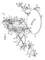
- FIG. 1 is a schematic perspective view showing the working conditions of an embodiment of the apparatus according to the invention
- Fig. 2 is its block diagram.
- the automatic continuous analysis apparatus 1 using this analytical implement comprises an analytical-implement automatic handling device 3 arranged around it with an analytical-implement automatic supply device 4, a sample-vessel supply device 5 and an optical measurement device 6.
- reference numeral 7 indicates a control section provided with a CPU, clock device, etc.
- numeral 8 indicates an input section, and 9, an output section.
- the analytical-implement automatic handling device 3 comprises an arm 12 provided with an analytical implement holder 11 on its end an arm driving means.
- the arm driving means supports a rotating section 15 comprising the arm, 12 an arm driving shaft 13, and a shaft rotating motor 14 with vertical shafts 17, and hangs it movably in up-and-down direction with a wire 19 wound round the shaft of a vertically driving motor 18. It also drives in right-and-left direction the slider 16 which supports one end of the arm driving shaft 13 to stop swing motion, with a wire 21 wound round the shaft of a right-and-left driving motor 20.
- the slider 16 is supported by right-and-left driving shafts 22, and the whole structure is built in a frame 23.
- the analytical implement holder 11 of this embodiment has a grip device which is opened and closed by pushing an pulling of a release 24.
- the release 24 is operated by a solenoid 25 in this embodiment.
- the operation of the release may also by effected by an air cylinder or rotating cam, or the operation of the grip device may be directly effected by a solenoid or air cylinder.
- a system which directly holds the analytical implement by air suction instead of the grip device may be used.
- the release type is desirable, being light and strong.
- These release and air pie may be passed through the arm 12, or may be set afloat in the space.
- Motors 14, 18, and 20 are preferably pulse motors suitable to accurate positioning.
- the analytical-implement automatic handling device 3 is not limited to the one shown in the drawings.
- a small-sized simple robot or any structure that can move the arm 12 up-and-down, right-and-left, and in circular motion by use of a motor and wire, screw thread, cylinder, etc. can be used.
- C Analytical-implement automatic supply device
- the analytical implement automatic supply device 4 is for supplying analytical implements one by one, and various structures are considerable.
- a hopper type as shown in Fig..4 to Fig. 14 is used.
- the hopper 26 for putting in analytical implements comprises a bottom section 28 provided with an analytical-implement groove 27 and a side section 29 and moves the analytical implement groove 27 to the outside of the hopper by sliding the bottom section 28.
- the bottom section is moved by a wire 30 connected to the front and back of the bottom section 28 and driven by a motor 31.
- the motor 31 is preferably a pulse motor.
- Figure 4 is a perspective view showing an example of the analytical-implement automatic supply device 4
- Figs. 5 and 6 are .its vertical sections
- Fig. 7 is partial section.
- the analytical implement groove 27 is provided at right angles to the moving direction of the bottom section 28, for accommodating only one piece of the analytical implement 2.
- the side section 29 comprises two wall sections 33 and 34 intersecting at right angles to the moving direction of the bottom section and two wall sections 35 and 36 which are parallel with the moving direction of the bottom section 28.
- the inside surfaces 33a and 34a of the wall sections 33 and 34 are parallel with the groove 27 viewed in plane (the lower edges of the inside walls are parallel with the longitudinal direction of the groove 27) and the section enclosed by the four inside walls and the bottom forms a storage section 37 for analytical implements 2.
- the bottom section 28 is narrower than the space between the wall sections 35 and 16 and is provided with some clearances therebetween.
- reference number 38 indicates a detector for detecting the presence of analytical implements 2
- 39 is the inverting plate of an inverting device
- 40 is a presser lever for pressing the analytical implement 2 in the groove 27 which has stopped outside the hopper
- 41 is a shade fixed to the lower side face of the bottom section
- 42 is a detector provided on the side of the shade 41 for detecting the position of the bottom section 28
- 43 is a rotary encoder attached to the shaft of the motor 31.
- the movement of the bottom section 28 is reversed when the groove 27 comes to position A and to position D by the reversal of the motor 31 according to the signal given by the detector 24 detecting the shade 41 to be absent.
- the motor rotates further for certain pulses or time to send the bottom section 28 in normal direction.
- the presser lever 40 which is driven by the motor 44 presses down the analytical implement 2 into the groove 27. This is to secure the holding of the analytical implement 2 by the analytical implement holder 11, suppressing floating.
- the suspension continues until the next action command is delivered.
- the action command is delivered by the control section 7 after a specified time has elapsed from the end of the preceding suspension or after detecting the fact that the analytical-implement automatic handling device has taken out the analytical implement 2 from the groove 27. If no analytical implement is found in the groove 27, the bottom section 28 goes back from position C and continues the reciprocating motion until an analytical implement 2 is caught by the groove 27.
- the analytical implements 2 are arranged in parallel with the groove 27 in the inside wall section as the bottom section 28 moves and become easy to be caught by the groove 27.
- the left inside wall surface 34a inclined as shown is convenient for stirring the analytical implements in the inside wall section 34a and for taking an analytical implement 2 incompletely caught by the groove 27.
- the inside wall surface 33a in right side may be vertical, but preferably be chamferred to lead analytical implements even with some warp smoothly into the groove. (v) On the other hand, it is necessary to stop the movement of the bottom sections 28 immediately when any disorder is detected, since if an analytical implement 2 is caught in the gap between the bottom section 28 and the bottom edge of the wall section 33, the reagent section 2B can be damaged.
- a rotary encoder 43 is used in this embodiment.
- a detector 46 such as transmission type photointerruptor inputs regular light-and-dark pulse signals into the control section 7 as the bottom section 28 moves.
- the pulse signals are disturbed. This detected and immediately stops the motor 31.
- An alternate system may be used in which the analytical implement 2 is moved in reverse direction somewhat, and then in normal direction. If no disorder is found, then the operation is continued as it is.
- the motor has preferably has weak torque or provided with a clutch device which cuts the torque exceeding a specified value.
- detecting means is shown in . F ig. 9. It has a perforated plate 48 having a number of small holes 47 bored regularly in small intervals and fixed to the lower part of the bottom section 28. It is monitored by the detector 46 in the same manner as the above. (vi) To check the presence of an analytical implement 2 in the groove 27, use of one detector 38 is sufficient. If a plurality of detectors, the same type or different types, are used, top-bottom judgment or detection of unacceptable one become possible.
- the presence of an analytical implement is detected, for example, by checking the shade of the analytical implement 2 (reagent section 2B or coating layer 2E) with a transmission type photo-interruptor.
- the top-bottom judgment is made, for example, from the difference of the quantity of reflected light from the top (reagent section 2B) and from the bottom (black adhesive tape 2D), using a reflection type photo-interruptor.
- the detection of the presence and top-bottom judgment of an analytical implement may also be made as follows:
- detectors 38 it is possible to provide a plurality of detectors 38 to monitor the individual reagent sections, to make discrimination of the type and inspection of defectives (e.g. those having peeled reagent section 2B or scar) by the variation of the quantity of reflected light, and to remove non-conforming one such as different types and defectives out of the system.
- Various types of detectors 38 can be used in combination.
- the detectors 38 can be installed in various positions such as inside or outside of the wall section 33, not limited to those as shown.
- the arm of the analytical-implement automatic handling device 3 has the function to invert the analytical implement 2, it is sufficient to give to the analytical-implement handling device 3 only the information that the top and bottom of the implement is inverted. Otherwise, those facing wrong side must be inverted so that all the reagent sections 2B point the same direction, upward or downward.
- This inversion is effected by inversion plates 39 attached to a bar 49 mounted across the walls 35 and 36 above the inverting position E. (Fig. 5)
- the inversion plates 39 are positioned on both sides of the bottom section 28 and at the longitudinal groove 45.
- the motor 31 makes excessive normal rotations for certain pulses or a certain time to bring the bottom section 28 to a position where the groove 27 goes over the rest position D (chain line in Fig. 8 (a)).
- This inverts the analytical implement 2 in the groove 27 along the curved surfaces of the inversion plates 39 (Fig. 8 (b)).
- the analytical implement 2 is shifted toward the wall section 33 out of the groove 27.
- the bottom section 28 goes back and drops the analytical implement 2 into the groove 27 with the interceptors 50 which are united with the inversion plates 39 (Fig. 8 (c)). It may be dropped by the bottom edge of the outer wall of the wall section 33, instead of the interceptor.
- the bottom section 28 successively goes back and is checked by the detector 38. If the reagent section 2B is ascertained to point upward correctly, the bottom section goes back from this point to the rest position D (chain line in Fig. 8 (c)) of the groove.
- FIG. 10 Another possible example of the inversion device is shown in Fig. 10. It comprises levers 52 rotatable supported through a shaft by the wall sections 35 and 26 outside the hopper 26, and pins 53, 53 projecting toward both sides from the lower front of the bottom section 28.
- the bottom section 28 goes in normal direction and the levers 52 stands up being pushed by pins 53 at their lower portions. This pushes out analytical implement 2 in the groove 27 and inverts it (Fig. 10 (b)).
- the implement 2 which has been pushed out and inverted is then dropped back into the groove 27 by the bottom edge of the outer wall of the wall section 33.
- One possible method to deal with this problem is to deliver an instruction from the control section 7, when the detector 38 has detected a disorder, to once return the groove 27 to position B and take out a new analytical implement 2.
- a mechanism to remove non-conforming analytical implement may be provided.
- the inversion device shown Fig. 10 can be used directly.
- An analytical implement 2 caught in the groove 27 in normal direction as shown in Fig. 11 (a) is inverted by the inversion levers 52 as shown in Fig. 1 (b).
- the bottom section 28 is moved further in normal direction to bring down the levers 52 (Fig. 11 (c)).
- the bottom section 28 is moved backward to return the levers 52 to the original posture and moved further backward to release the analytical implement into the a chute 54 (Fig. 1 (d)).
- Levers 56 different from the levers 55 as shown in Fig. 12 can be used for removing non-conforming implements and the levers 55 and 56 may be driven by motors independently from each other.
- the bottom section 28 is provided with longitudinal cuts 57 and 58 for passing levers 55 and 56 therethrough.
- cassette type can be used.
- Figure 15 shows an example of such type.
- Many analytical implements packed in a cassette 69 is pushed out by a slider 70 one by one from the bottom and placed on the take- out position and ascertained by a detector 71. They are then picked up by the'analytical-implement holder 11 from this position.
- This example of the sample vessel supply device 5 is of a turntable system.
- the turntable 72 is provided with many ports for receiving sample vessels 73 in the peripheral section and rotated in normal and reverse directions by a motor 75. If the turntable is made replaceable and successively changed, a great deal of samples can be tactfully treated.
- the optical measurement device 6 comprises a light measuring section 76 and a reaction turntable 77 for leading the analytical implement 2 placed thereon.
- the reaction turntable 77 is provided radially thereon with a plurality of grooves 78 for putting an analytical implement 2 therein, and rotated intermittently in a direction by a motor 79.
- the light measuring section 76 is placed above a position where the groove 78 halts.
- the light measuring section 76 comprises an optical system 80 and a pulling device for moving the analytical implement 2.
- the motors 75 and 79 are preferably pulse motors.
- the arm 12 of the analytical-implement automatic handling device 3 is moved outward (leftward in the drawing) by the rotation of the motor 20.
- the rotary section 15 is brought down by the rotation of the motor 18 and the analytical-implement holder 11 is brought to the analytical-implement takeout position X of the analytical-implement automatic supply device 4.
- the open analytical implement holder 1 closes after catching the holding section of the analytical implement 2.
- the motors 18 and 20 rotate in reverse direction, and the motor 14 for shaft rotation rotates to bring the analytical implement holder 11 to position Y for dipping the analytical implement in the dipping solution.
- the analytical implement holder 11 is lowered to dip the reagent section 2B in the sample solution for a specified time.
- the motor 18 rotates to pull up the analytical implement 2, and the motors 18 and 14 rotate to bring the analytical implement holder 11 to the position Z of the turntable groove 78 on the optical measurement device.
- the analytical implement holder 11 puts the analytical implement 2 into the groove 78 by lowering from upper side or by inserting it from the peripheral direction of the turntable.
- the analytical implement 2 is sent to the light measuring section 76 by turning turntable 77, and measured. Then, the analytical implement holder 11 returns to position X and repeats the same action.
- the liquid level detector is then described.
- the analytical implement 2 is automatically inserted into the sample vessel 73, if the sample solution is wanting in the vessel, the reagent section 2B fails to be dipped, or if it is too much, the dipping time becomes too long. Thus, accurate measurement is not to be expected.
- the liquid level detection is effected, for example, by two long and short electrodes 87 and 88 supported on the end of the nozzle arm.
- the nozzle arm 86 is driven by a nozzle motor 89, and the electrodes 87 and 88 are washed in a washing tank 90 every measurement.
- the long electrodes 87 can be used also as a suction nozzle to suck and lead the solution to a specific gravity unit 90 for specific gravity measurement.
- suction prior to analytical implement dipping can lower the liquid level, it is favorable to estimate the quantity or detect the liquid level in advance, and make dipping before suction.
- the liquid level detection may be effected by an optical sensor using reflected light.
- the method according to the invention holds up the analytical implement successively supplied by the supplier by gripping its holding section, and after dipping the reagent section on the analytical implement in the sample solution in the sample vessel which is successively delivered, for a specified time,sets the analytical implement on the table, and after a specified time measures the light reflected by the reagent section.
- the analytical implement supply device used in the invention stores analytical implements in the space enclosed by the bottom section having an analytical implement groove and two parallel walls which are parallel to the analytical implement groove, and takes out the analytical implements one by one fitted in the groove, by relatively reciprocating the bottom section to the walls.
- the analytical implement can be taken out certainly one by one with the reagent sections directed in one direction certainly, only by putting them in the storage section with their holding sections arranged.
- normal analytical implements on the market can be used, and screening of different types of it and checking out of defectives are possible, leading to increased reliability of the measurements. It is simple in structure and operation
Landscapes
- Physics & Mathematics (AREA)
- Health & Medical Sciences (AREA)
- Life Sciences & Earth Sciences (AREA)
- Chemical & Material Sciences (AREA)
- Analytical Chemistry (AREA)
- Biochemistry (AREA)
- General Health & Medical Sciences (AREA)
- General Physics & Mathematics (AREA)
- Immunology (AREA)
- Pathology (AREA)
- Automatic Analysis And Handling Materials Therefor (AREA)
Applications Claiming Priority (6)
| Application Number | Priority Date | Filing Date | Title |
|---|---|---|---|
| JP21359284 | 1984-10-11 | ||
| JP213592/84 | 1984-10-11 | ||
| JP21359284A JPS6191571A (ja) | 1984-10-11 | 1984-10-11 | 試験片を用いる連続自動分析方法及び装置 |
| JP59232678A JPH0665990B2 (ja) | 1984-11-05 | 1984-11-05 | 体液成分分析における自動分析用帯状試験片の自動供給方法及び供給装置 |
| JP23267884 | 1984-11-05 | ||
| JP232678/84 | 1984-11-05 |
Publications (4)
| Publication Number | Publication Date |
|---|---|
| EP0180792A2 true EP0180792A2 (fr) | 1986-05-14 |
| EP0180792A3 EP0180792A3 (en) | 1987-01-07 |
| EP0180792B1 EP0180792B1 (fr) | 1990-03-28 |
| EP0180792B2 EP0180792B2 (fr) | 1999-09-01 |
Family
ID=26519879
Family Applications (1)
| Application Number | Title | Priority Date | Filing Date |
|---|---|---|---|
| EP85112715A Expired - Lifetime EP0180792B2 (fr) | 1984-10-11 | 1985-10-08 | Procédé et dispositif pour l'analyse automatique et continue à l'aide d'un appareil analytique |
Country Status (4)
| Country | Link |
|---|---|
| US (1) | US4876204A (fr) |
| EP (1) | EP0180792B2 (fr) |
| CN (1) | CN85108392A (fr) |
| DE (1) | DE3576857D1 (fr) |
Cited By (10)
| Publication number | Priority date | Publication date | Assignee | Title |
|---|---|---|---|---|
| EP0286101A2 (fr) * | 1987-04-07 | 1988-10-12 | Kabushiki Kaisha Kyoto Daiichi Kagaku | Méthode pour analyser des composants spécifiques dans des liquides |
| EP0336126A2 (fr) * | 1988-03-08 | 1989-10-11 | Roche Diagnostics GmbH | Dispositif de transfert de bandes test vers un appareil d'analyse |
| EP0474145A2 (fr) * | 1990-09-05 | 1992-03-11 | Kyoto Daiichi Kagaku Co., Ltd. | Analysateur automatique d'échantillons |
| EP0538830A1 (fr) * | 1991-10-21 | 1993-04-28 | Hitachi, Ltd. | Méthode et dispositif d'analyse utilisant éléments d'analyse |
| EP0555654A2 (fr) * | 1992-01-16 | 1993-08-18 | Fuji Photo Film Co., Ltd. | Système d'analyses chimique |
| EP0594108A1 (fr) * | 1992-10-19 | 1994-04-27 | Hitachi, Ltd. | Appareil d'analyse automatique d'échantillon liquide |
| EP0597419A1 (fr) * | 1992-11-11 | 1994-05-18 | Hitachi, Ltd. | Dispositif de distribution de bandes d'essai et analyseur l'utilisant |
| FR2737574A1 (fr) * | 1995-08-03 | 1997-02-07 | Pasteur Institut | Appareillage d'alignement parallele de macromolecules et utilisation |
| ES2133019A1 (es) * | 1994-05-10 | 1999-08-16 | Bayer Ag | Sistema de suministro automatizado. |
| IT201600111889A1 (it) * | 2016-11-07 | 2018-05-07 | Ima Spa | Gruppo di misura per ottenere informazioni correlate ad una sostanza e relativo procedimento |
Families Citing this family (47)
| Publication number | Priority date | Publication date | Assignee | Title |
|---|---|---|---|---|
| US4935346A (en) | 1986-08-13 | 1990-06-19 | Lifescan, Inc. | Minimum procedure system for the determination of analytes |
| JPH02163637A (ja) * | 1988-12-16 | 1990-06-22 | Fuji Photo Film Co Ltd | 液体化学分析装置 |
| US5043143A (en) * | 1990-03-28 | 1991-08-27 | Eastman Kodak Company | Analyzer having humidity control apparatus |
| JP3041404B2 (ja) * | 1990-11-16 | 2000-05-15 | セイコーインスツルメンツ株式会社 | オートサンプリング機構 |
| JP2771367B2 (ja) * | 1991-11-14 | 1998-07-02 | 株式会社日立製作所 | 試験片供給装置およびそれを用いた分析装置 |
| DE4204245A1 (de) * | 1992-02-13 | 1993-08-19 | Boehringer Mannheim Gmbh | Vorrichtung zum lagerichtigen zufuehren von teststreifen zu einer analyseeinrichtung |
| US5646049A (en) | 1992-03-27 | 1997-07-08 | Abbott Laboratories | Scheduling operation of an automated analytical system |
| US5578494A (en) | 1992-03-27 | 1996-11-26 | Abbott Laboratories | Cap actuator for opening and closing a container |
| US5960160A (en) | 1992-03-27 | 1999-09-28 | Abbott Laboratories | Liquid heater assembly with a pair temperature controlled electric heating elements and a coiled tube therebetween |
| US5610069A (en) | 1992-03-27 | 1997-03-11 | Abbott Laboratories | Apparatus and method for washing clinical apparatus |
| US6190617B1 (en) | 1992-03-27 | 2001-02-20 | Abbott Laboratories | Sample container segment assembly |
| US5635364A (en) | 1992-03-27 | 1997-06-03 | Abbott Laboratories | Assay verification control for an automated analytical system |
| US5627522A (en) | 1992-03-27 | 1997-05-06 | Abbott Laboratories | Automated liquid level sensing system |
| US5540890A (en) | 1992-03-27 | 1996-07-30 | Abbott Laboratories | Capped-closure for a container |
| US5507410A (en) | 1992-03-27 | 1996-04-16 | Abbott Laboratories | Meia cartridge feeder |
| US5605665A (en) | 1992-03-27 | 1997-02-25 | Abbott Laboratories | Reaction vessel |
| US5536471A (en) | 1992-03-27 | 1996-07-16 | Abbott Laboratories | Syringe with bubble flushing |
| US5376313A (en) | 1992-03-27 | 1994-12-27 | Abbott Laboratories | Injection molding a plastic assay cuvette having low birefringence |
| US5575978A (en) | 1992-03-27 | 1996-11-19 | Abbott Laboratories | Sample container segment assembly |
| US5332549A (en) * | 1992-07-01 | 1994-07-26 | Pb Diagnostic Systems, Inc. | Assay module transport apparatus for use in an automated analytical instrument |
| KR970010962B1 (ko) * | 1992-12-28 | 1997-07-05 | 조말수 | 액체시료 자동분석장치 |
| JP3246058B2 (ja) * | 1993-04-13 | 2002-01-15 | 株式会社日立製作所 | 試験片供給装置 |
| US5534224A (en) * | 1993-07-16 | 1996-07-09 | Fuji Photo Film Co., Ltd. | Chemical analysis film cartridge |
| JP3425795B2 (ja) * | 1994-03-11 | 2003-07-14 | 富士写真フイルム株式会社 | 分析フイルム片有無判定方法 |
| JP3331253B2 (ja) * | 1994-05-10 | 2002-10-07 | バイエルコーポレーション | 自動分析装置の試験片取出装置 |
| JP3331255B2 (ja) * | 1994-05-10 | 2002-10-07 | バイエルコーポレーション | 自動分析装置の試験片反転機構 |
| JP3036353B2 (ja) * | 1994-05-11 | 2000-04-24 | 株式会社日立製作所 | 試験片供給装置 |
| DE4425432A1 (de) * | 1994-07-19 | 1996-01-25 | Boehringer Mannheim Gmbh | Auswertevorrichtung zur reflektometrischen Auswertung von Testelementen |
| DE4425439A1 (de) * | 1994-07-19 | 1996-01-25 | Boehringer Mannheim Gmbh | Teststreifenauswertegerät mit einer Transporteinheit für Teststreifen |
| US6335203B1 (en) * | 1994-09-08 | 2002-01-01 | Lifescan, Inc. | Optically readable strip for analyte detection having on-strip orientation index |
| US6660233B1 (en) * | 1996-01-16 | 2003-12-09 | Beckman Coulter, Inc. | Analytical biochemistry system with robotically carried bioarray |
| US6458326B1 (en) | 1999-11-24 | 2002-10-01 | Home Diagnostics, Inc. | Protective test strip platform |
| US6541266B2 (en) | 2001-02-28 | 2003-04-01 | Home Diagnostics, Inc. | Method for determining concentration of an analyte in a test strip |
| US6525330B2 (en) | 2001-02-28 | 2003-02-25 | Home Diagnostics, Inc. | Method of strip insertion detection |
| US6562625B2 (en) | 2001-02-28 | 2003-05-13 | Home Diagnostics, Inc. | Distinguishing test types through spectral analysis |
| DE50309876D1 (de) * | 2002-10-29 | 2008-07-03 | Roche Diagnostics Gmbh | Testelementanalysesystem |
| AU2003296703A1 (en) * | 2002-12-23 | 2004-07-14 | F.Hoffmann-La Roche Ag | Transport device for transporting test strips in an analysis system |
| JP3890369B2 (ja) * | 2003-01-31 | 2007-03-07 | アークレイ株式会社 | 分析具供給装置 |
| US7097070B2 (en) | 2003-08-15 | 2006-08-29 | Protedyne Corporation | Method and apparatus for handling small volume fluid samples |
| CN1871520B (zh) | 2003-10-22 | 2012-06-06 | 爱科来株式会社 | 分析器具供给装置 |
| US7862772B2 (en) * | 2003-10-22 | 2011-01-04 | Arkray, Inc. | Analyzer-supplying device |
| DE102004010529B4 (de) * | 2004-03-04 | 2007-09-06 | Roche Diagnostics Gmbh | Analysehandgerät |
| WO2005119268A1 (fr) * | 2004-06-02 | 2005-12-15 | Arkray, Inc. | Mécanisme de sélection de sens pour outil analytique, et dispositif analytique |
| AU2005202624A1 (en) * | 2004-06-28 | 2006-01-12 | Lifescan Scotland Limited | Resealable vial and dispensing mechanism for test sensor |
| CN102608338B (zh) * | 2012-02-23 | 2013-04-10 | 长沙高新技术产业开发区爱威科技实业有限公司 | 全自动干化学分析仪测试条分送装置 |
| USD743559S1 (en) * | 2012-09-07 | 2015-11-17 | Zhuhai Womu Electronic Co., Ltd. | Dynamic urine monitoring device |
| JP6255198B2 (ja) * | 2013-09-26 | 2017-12-27 | テラメックス株式会社 | 試験片ピックアップ機構及び試験片移動装置 |
Citations (10)
| Publication number | Priority date | Publication date | Assignee | Title |
|---|---|---|---|---|
| US3348418A (en) * | 1963-08-13 | 1967-10-24 | Intertech Inc | Automatic sample changer |
| US3980437A (en) * | 1974-12-21 | 1976-09-14 | Kabushiki Kaisha Kyoto Daiichi Kagaku | Test strips and methods and apparatus for using the same |
| US4125372A (en) * | 1975-04-01 | 1978-11-14 | Kabushiki Kaisha Kyoto Kaiichi Kagaku | Method and device for testing liquids |
| GB2013334A (en) * | 1978-01-25 | 1979-08-08 | Kyoata Daiichi Kagaku Kk | Analysis with colour identification test paper |
| GB2014113A (en) * | 1978-01-30 | 1979-08-22 | Labora Mannheim Gmbh | Feeding test strips through an evaluating device |
| US4269803A (en) * | 1979-07-02 | 1981-05-26 | Eastman Kodak Company | Slide transfer mechanism |
| GB2096314A (en) * | 1981-03-26 | 1982-10-13 | Lre Relais & Elektronik Gmbh | Apparatus for optoelectric evaluation of test paper strips |
| EP0064691A1 (fr) * | 1981-05-13 | 1982-11-17 | Miles Laboratories, Inc. | Dispositif comprenant un magasin retenant une pluralité de feuillets indicateurs souples et des moyens pour en extraire un seul ainsi que procédé de distribution de tels feuillets utilisant cet appareil |
| JPS58156833A (ja) * | 1982-03-15 | 1983-09-17 | Konishiroku Photo Ind Co Ltd | 液体試料分析装置 |
| EP0098773A1 (fr) * | 1982-07-01 | 1984-01-18 | EASTMAN KODAK COMPANY (a New Jersey corporation) | Dispositif pour stocker et distribuer des lamelles d'analyse |
Family Cites Families (8)
| Publication number | Priority date | Publication date | Assignee | Title |
|---|---|---|---|---|
| US2652139A (en) * | 1952-01-15 | 1953-09-15 | Wiesner Rapp Company Inc | Feeder |
| US3645690A (en) * | 1968-01-22 | 1972-02-29 | Beckman Instruments Inc | Automated chemical analyzer |
| US3760956A (en) * | 1971-08-23 | 1973-09-25 | Burch Controls Inc | Industrial robot |
| US3918910A (en) * | 1973-07-31 | 1975-11-11 | Olympus Optical Co | System for detecting the particular chemical constituent of a fluid |
| US3951271A (en) * | 1974-05-03 | 1976-04-20 | Mette Klaus Hermann | Robot control device |
| GB1591026A (en) * | 1976-09-15 | 1981-06-10 | Schlaepfer & Co Ag | Transfers for the decoration of sheet materials |
| US4152390A (en) * | 1976-12-17 | 1979-05-01 | Eastman Kodak Company | Chemical analyzer |
| JPS5782769A (en) * | 1980-11-10 | 1982-05-24 | Hitachi Ltd | Automatic analyzing device |
-
1985
- 1985-10-01 US US06/782,356 patent/US4876204A/en not_active Expired - Lifetime
- 1985-10-08 EP EP85112715A patent/EP0180792B2/fr not_active Expired - Lifetime
- 1985-10-08 DE DE8585112715T patent/DE3576857D1/de not_active Expired - Lifetime
- 1985-10-09 CN CN198585108392A patent/CN85108392A/zh active Pending
Patent Citations (10)
| Publication number | Priority date | Publication date | Assignee | Title |
|---|---|---|---|---|
| US3348418A (en) * | 1963-08-13 | 1967-10-24 | Intertech Inc | Automatic sample changer |
| US3980437A (en) * | 1974-12-21 | 1976-09-14 | Kabushiki Kaisha Kyoto Daiichi Kagaku | Test strips and methods and apparatus for using the same |
| US4125372A (en) * | 1975-04-01 | 1978-11-14 | Kabushiki Kaisha Kyoto Kaiichi Kagaku | Method and device for testing liquids |
| GB2013334A (en) * | 1978-01-25 | 1979-08-08 | Kyoata Daiichi Kagaku Kk | Analysis with colour identification test paper |
| GB2014113A (en) * | 1978-01-30 | 1979-08-22 | Labora Mannheim Gmbh | Feeding test strips through an evaluating device |
| US4269803A (en) * | 1979-07-02 | 1981-05-26 | Eastman Kodak Company | Slide transfer mechanism |
| GB2096314A (en) * | 1981-03-26 | 1982-10-13 | Lre Relais & Elektronik Gmbh | Apparatus for optoelectric evaluation of test paper strips |
| EP0064691A1 (fr) * | 1981-05-13 | 1982-11-17 | Miles Laboratories, Inc. | Dispositif comprenant un magasin retenant une pluralité de feuillets indicateurs souples et des moyens pour en extraire un seul ainsi que procédé de distribution de tels feuillets utilisant cet appareil |
| JPS58156833A (ja) * | 1982-03-15 | 1983-09-17 | Konishiroku Photo Ind Co Ltd | 液体試料分析装置 |
| EP0098773A1 (fr) * | 1982-07-01 | 1984-01-18 | EASTMAN KODAK COMPANY (a New Jersey corporation) | Dispositif pour stocker et distribuer des lamelles d'analyse |
Non-Patent Citations (3)
| Title |
|---|
| ANALYTICAL CHEMISTRY, vol. 56, no. 4, April 1984, pages 742-745, Easton, US; W.E. NEELEY : "Reflectance photometer for multiplayer dry film slides", page 742, column 2, lines 22-25; figure 2. * |
| PATENT ABSTRACTS OF JAPAN, vol. 7, no. 278 (P-242) (1423), December 10th, 1983; & JP,A,58 156 833 (KONISHIROKU SHASHIN KOGYO K.K.) 17-09-1983 * |
| RESEARCH DISCLOSURE, no. 197, September 1980, Havart, GB; "Slide transfer apparatus", pages 375-376 * |
Cited By (21)
| Publication number | Priority date | Publication date | Assignee | Title |
|---|---|---|---|---|
| EP0286101A3 (en) * | 1987-04-07 | 1990-04-11 | Kabushiki Kaisha Kyoto Daiichi Kagaku | A method for analyzing special component in liquid |
| EP0286101A2 (fr) * | 1987-04-07 | 1988-10-12 | Kabushiki Kaisha Kyoto Daiichi Kagaku | Méthode pour analyser des composants spécifiques dans des liquides |
| US5097938A (en) * | 1988-03-08 | 1992-03-24 | Boehringer Mannheim Gmbh | Apparatus for transferring test strips to an examining apparatus |
| EP0336126A2 (fr) * | 1988-03-08 | 1989-10-11 | Roche Diagnostics GmbH | Dispositif de transfert de bandes test vers un appareil d'analyse |
| EP0336126A3 (en) * | 1988-03-08 | 1990-07-04 | Boehringer Mannheim Gmbh | Device for transferring test stripes to an analyser |
| US5270006A (en) * | 1990-09-05 | 1993-12-14 | Kyoto Daiichi Kagaku Co., Ltd. | Automatic sample analyzer |
| EP0474145A2 (fr) * | 1990-09-05 | 1992-03-11 | Kyoto Daiichi Kagaku Co., Ltd. | Analysateur automatique d'échantillons |
| EP0474145A3 (en) * | 1990-09-05 | 1993-03-03 | Kyoto Daiichi Kagaku Co., Ltd. | Automatic sample analyzer |
| EP0538830A1 (fr) * | 1991-10-21 | 1993-04-28 | Hitachi, Ltd. | Méthode et dispositif d'analyse utilisant éléments d'analyse |
| US5460968A (en) * | 1991-10-21 | 1995-10-24 | Hitachi, Ltd. | Analytical method and analytical apparatus using test strips |
| EP0555654A3 (en) * | 1992-01-16 | 1993-11-03 | Fuji Photo Film Co Ltd | Chemical analysis system |
| US5447690A (en) * | 1992-01-16 | 1995-09-05 | Fuji Photo Film Co., Ltd. | Chemical analysis system |
| EP0555654A2 (fr) * | 1992-01-16 | 1993-08-18 | Fuji Photo Film Co., Ltd. | Système d'analyses chimique |
| EP0594108A1 (fr) * | 1992-10-19 | 1994-04-27 | Hitachi, Ltd. | Appareil d'analyse automatique d'échantillon liquide |
| US5415840A (en) * | 1992-10-19 | 1995-05-16 | Hitachi, Ltd. | Liquid sample automatic analyzer |
| EP0597419A1 (fr) * | 1992-11-11 | 1994-05-18 | Hitachi, Ltd. | Dispositif de distribution de bandes d'essai et analyseur l'utilisant |
| ES2133019A1 (es) * | 1994-05-10 | 1999-08-16 | Bayer Ag | Sistema de suministro automatizado. |
| FR2737574A1 (fr) * | 1995-08-03 | 1997-02-07 | Pasteur Institut | Appareillage d'alignement parallele de macromolecules et utilisation |
| WO1997006420A1 (fr) * | 1995-08-03 | 1997-02-20 | Institut Pasteur | Appareillage d'alignement parallele de macromolecules et utilisation |
| AU714938B2 (en) * | 1995-08-03 | 2000-01-13 | Institut Pasteur | Apparatus for the parallel alignment of macromolecules, and use thereof |
| IT201600111889A1 (it) * | 2016-11-07 | 2018-05-07 | Ima Spa | Gruppo di misura per ottenere informazioni correlate ad una sostanza e relativo procedimento |
Also Published As
| Publication number | Publication date |
|---|---|
| EP0180792B1 (fr) | 1990-03-28 |
| CN85108392A (zh) | 1986-06-10 |
| US4876204A (en) | 1989-10-24 |
| EP0180792B2 (fr) | 1999-09-01 |
| EP0180792A3 (en) | 1987-01-07 |
| DE3576857D1 (de) | 1990-05-03 |
Similar Documents
| Publication | Publication Date | Title |
|---|---|---|
| US4876204A (en) | Method and apparatus of automatic continuous analysis using analytical implement | |
| JP3368985B2 (ja) | 自動供給装置 | |
| US5169600A (en) | Biochemical analysis apparatus for incubating and analyzing test sites on a long tape test film | |
| EP0299519B1 (fr) | Appareil d'analyses biochimiques | |
| CA1254411A (fr) | Appareil pour le traitement de lames pour analyses | |
| EP0918221B1 (fr) | Appareil pour réaliser automatiquement des tests de laboratoire | |
| US5250440A (en) | Cuvette delivery module and turntable for a chemical analyzer | |
| US4861554A (en) | Automatic analyzing apparatus for analyzing agglutination patterns | |
| JP2601075B2 (ja) | 試験片を用いる分析方法および分析装置 | |
| US5139743A (en) | Biochemical analysis apparatus | |
| JP2008026051A (ja) | 生化学自動分析装置 | |
| US8017077B2 (en) | Staining and sticking system | |
| JPH06130067A (ja) | 液体試料自動分析装置 | |
| WO2015046425A1 (fr) | Mécanisme de ramassage d'éprouvettes, appareil de déplacement d'éprouvettes, appareil d'analyse d'échantillons liquides et procédé de ramassage d'éprouvettes | |
| EP0677744B1 (fr) | Procédé et appareil pour déposer des échantillons liquides sur des éléments d'analyse secs | |
| JPH0572216A (ja) | 臨床検査用の自動分析装置 | |
| US5378630A (en) | Test strip automatic supply device and analytical instrument using the same | |
| WO2020235134A1 (fr) | Dispositif d'analyse automatique | |
| EP1889662A1 (fr) | Procédé pour la normalisation de la tension de surface d'un échantillon fluide | |
| JP3036353B2 (ja) | 試験片供給装置 | |
| JPH0665990B2 (ja) | 体液成分分析における自動分析用帯状試験片の自動供給方法及び供給装置 | |
| JPS6191571A (ja) | 試験片を用いる連続自動分析方法及び装置 | |
| JP3341591B2 (ja) | カートリッジ供給装置 | |
| JP3246058B2 (ja) | 試験片供給装置 | |
| US20230204615A1 (en) | Sample measuring method, cartridge, and sample measuring device |
Legal Events
| Date | Code | Title | Description |
|---|---|---|---|
| PUAI | Public reference made under article 153(3) epc to a published international application that has entered the european phase |
Free format text: ORIGINAL CODE: 0009012 |
|
| AK | Designated contracting states |
Kind code of ref document: A2 Designated state(s): DE FR GB IT |
|
| PUAL | Search report despatched |
Free format text: ORIGINAL CODE: 0009013 |
|
| 17P | Request for examination filed |
Effective date: 19861014 |
|
| AK | Designated contracting states |
Kind code of ref document: A3 Designated state(s): DE FR GB IT |
|
| 17Q | First examination report despatched |
Effective date: 19880627 |
|
| GRAA | (expected) grant |
Free format text: ORIGINAL CODE: 0009210 |
|
| AK | Designated contracting states |
Kind code of ref document: B1 Designated state(s): DE FR GB IT |
|
| REF | Corresponds to: |
Ref document number: 3576857 Country of ref document: DE Date of ref document: 19900503 |
|
| ITF | It: translation for a ep patent filed | ||
| ET | Fr: translation filed | ||
| PLBI | Opposition filed |
Free format text: ORIGINAL CODE: 0009260 |
|
| 26 | Opposition filed |
Opponent name: BOEHRINGER MANNHEIM GMBH Effective date: 19901201 |
|
| ITTA | It: last paid annual fee | ||
| PLAW | Interlocutory decision in opposition |
Free format text: ORIGINAL CODE: EPIDOS IDOP |
|
| APAE | Appeal reference modified |
Free format text: ORIGINAL CODE: EPIDOS REFNO |
|
| APAC | Appeal dossier modified |
Free format text: ORIGINAL CODE: EPIDOS NOAPO |
|
| APAC | Appeal dossier modified |
Free format text: ORIGINAL CODE: EPIDOS NOAPO |
|
| APAC | Appeal dossier modified |
Free format text: ORIGINAL CODE: EPIDOS NOAPO |
|
| PLAW | Interlocutory decision in opposition |
Free format text: ORIGINAL CODE: EPIDOS IDOP |
|
| PLAW | Interlocutory decision in opposition |
Free format text: ORIGINAL CODE: EPIDOS IDOP |
|
| PUAH | Patent maintained in amended form |
Free format text: ORIGINAL CODE: 0009272 |
|
| STAA | Information on the status of an ep patent application or granted ep patent |
Free format text: STATUS: PATENT MAINTAINED AS AMENDED |
|
| 27A | Patent maintained in amended form |
Effective date: 19990901 |
|
| AK | Designated contracting states |
Kind code of ref document: B2 Designated state(s): DE FR GB IT |
|
| RIC2 | Information provided on ipc code assigned after grant |
Free format text: 6G 01N 35/10 A, 6G 01N 33/52 B, 6B 65H 5/00 B, 6G 01N 1/12 B |
|
| ITF | It: translation for a ep patent filed | ||
| ET3 | Fr: translation filed ** decision concerning opposition | ||
| REG | Reference to a national code |
Ref country code: GB Ref legal event code: IF02 |
|
| PGFP | Annual fee paid to national office [announced via postgrant information from national office to epo] |
Ref country code: DE Payment date: 20040930 Year of fee payment: 20 |
|
| PGFP | Annual fee paid to national office [announced via postgrant information from national office to epo] |
Ref country code: GB Payment date: 20041006 Year of fee payment: 20 |
|
| PGFP | Annual fee paid to national office [announced via postgrant information from national office to epo] |
Ref country code: FR Payment date: 20041008 Year of fee payment: 20 |
|
| APAH | Appeal reference modified |
Free format text: ORIGINAL CODE: EPIDOSCREFNO |
|
| PG25 | Lapsed in a contracting state [announced via postgrant information from national office to epo] |
Ref country code: GB Free format text: LAPSE BECAUSE OF EXPIRATION OF PROTECTION Effective date: 20051007 |
|
| REG | Reference to a national code |
Ref country code: GB Ref legal event code: PE20 |