EP0141241B1 - Verfahren und Anordnung zur Auswahl einer Station in einer Gruppe von Stationen im Dialog mit einer Hauptstation - Google Patents
Verfahren und Anordnung zur Auswahl einer Station in einer Gruppe von Stationen im Dialog mit einer Hauptstation Download PDFInfo
- Publication number
- EP0141241B1 EP0141241B1 EP84111397A EP84111397A EP0141241B1 EP 0141241 B1 EP0141241 B1 EP 0141241B1 EP 84111397 A EP84111397 A EP 84111397A EP 84111397 A EP84111397 A EP 84111397A EP 0141241 B1 EP0141241 B1 EP 0141241B1
- Authority
- EP
- European Patent Office
- Prior art keywords
- station
- stations
- group
- main station
- link
- Prior art date
- Legal status (The legal status is an assumption and is not a legal conclusion. Google has not performed a legal analysis and makes no representation as to the accuracy of the status listed.)
- Expired
Links
- 238000000034 method Methods 0.000 title claims description 18
- 230000000694 effects Effects 0.000 claims description 2
- 238000011084 recovery Methods 0.000 claims description 2
- 230000003252 repetitive effect Effects 0.000 claims 2
- 230000005540 biological transmission Effects 0.000 description 7
- 230000002457 bidirectional effect Effects 0.000 description 5
- 230000008859 change Effects 0.000 description 4
- 238000010586 diagram Methods 0.000 description 4
- 239000000463 material Substances 0.000 description 3
- 230000007704 transition Effects 0.000 description 3
- 230000008901 benefit Effects 0.000 description 2
- 230000000903 blocking effect Effects 0.000 description 2
- 238000001514 detection method Methods 0.000 description 2
- 238000000605 extraction Methods 0.000 description 2
- 238000002347 injection Methods 0.000 description 2
- 239000007924 injection Substances 0.000 description 2
- 241000532784 Thelia <leafhopper> Species 0.000 description 1
- 230000006870 function Effects 0.000 description 1
- 230000007246 mechanism Effects 0.000 description 1
- 210000000056 organ Anatomy 0.000 description 1
- 230000008569 process Effects 0.000 description 1
- 238000009877 rendering Methods 0.000 description 1
- 230000033764 rhythmic process Effects 0.000 description 1
- 239000000243 solution Substances 0.000 description 1
- 230000001360 synchronised effect Effects 0.000 description 1
- 230000002123 temporal effect Effects 0.000 description 1
Images


Classifications
-
- H—ELECTRICITY
- H04—ELECTRIC COMMUNICATION TECHNIQUE
- H04L—TRANSMISSION OF DIGITAL INFORMATION, e.g. TELEGRAPHIC COMMUNICATION
- H04L12/00—Data switching networks
- H04L12/28—Data switching networks characterised by path configuration, e.g. LAN [Local Area Networks] or WAN [Wide Area Networks]
- H04L12/40—Bus networks
- H04L12/403—Bus networks with centralised control, e.g. polling
- H04L12/4035—Bus networks with centralised control, e.g. polling in which slots of a TDMA packet structure are assigned based on a contention resolution carried out at a master unit
-
- H—ELECTRICITY
- H04—ELECTRIC COMMUNICATION TECHNIQUE
- H04L—TRANSMISSION OF DIGITAL INFORMATION, e.g. TELEGRAPHIC COMMUNICATION
- H04L12/00—Data switching networks
- H04L12/28—Data switching networks characterised by path configuration, e.g. LAN [Local Area Networks] or WAN [Wide Area Networks]
- H04L12/40—Bus networks
- H04L12/40006—Architecture of a communication node
- H04L12/40013—Details regarding a bus controller
-
- H—ELECTRICITY
- H04—ELECTRIC COMMUNICATION TECHNIQUE
- H04L—TRANSMISSION OF DIGITAL INFORMATION, e.g. TELEGRAPHIC COMMUNICATION
- H04L12/00—Data switching networks
- H04L12/28—Data switching networks characterised by path configuration, e.g. LAN [Local Area Networks] or WAN [Wide Area Networks]
- H04L12/40—Bus networks
- H04L12/403—Bus networks with centralised control, e.g. polling
-
- H—ELECTRICITY
- H04—ELECTRIC COMMUNICATION TECHNIQUE
- H04Q—SELECTING
- H04Q11/00—Selecting arrangements for multiplex systems
- H04Q11/04—Selecting arrangements for multiplex systems for time-division multiplexing
-
- H—ELECTRICITY
- H04—ELECTRIC COMMUNICATION TECHNIQUE
- H04L—TRANSMISSION OF DIGITAL INFORMATION, e.g. TELEGRAPHIC COMMUNICATION
- H04L12/00—Data switching networks
- H04L12/28—Data switching networks characterised by path configuration, e.g. LAN [Local Area Networks] or WAN [Wide Area Networks]
- H04L12/40—Bus networks
- H04L12/40169—Flexible bus arrangements
Definitions
- the invention relates to the selection of a station from a set of stations dialoguing with a main station to which they are connected by a multiplex link constituted by at least one multiplex line for each direction of communication, the dialogue consisting in an exchange of messages transmitted in a reserved time channel of each frame of the multiplex lines which convey information in the form of coded pulses contained in channels of a frame; generally the frame has a duration of 125 microseconds and is divided into 32 time intervals known as time channels.
- the stations are terminal units connected to a certain number of subscribers and connected to a control unit equipped with a main station which consults said stations, this control unit itself being connected to the telecommunications center by a multiplex link.
- the stations dialogue with the main station by a reserved channel in the frames of the multiplex lines and the channel reserved for dialogue with the main station can be any of the 32 channels of the frame. There cannot be several stations which communicate with the main station at the same time; it is therefore necessary that the stations share the reserved channel in order to communicate one after the other.
- the election of a station can be done either by consultation or by centralized selection.
- the election by consultation all the stations are interrogated in a fixed order; when a station ready to broadcast meets, it is elected and the consultation stops; once the message has been sent, the consultation resumes.
- This method has the drawbacks of an exploration time that increases with the number of stations, and of an order of service unrelated to the order of requests.
- an arbitrator memorizes the requests of the different stations and proceeds to the election.
- the disadvantages lie in the complexity of the arbitrator and in the fact that the requests are also messages which must be transmitted on a specialized channel.
- a base station interrogates a subgroup of stations; the stations of the subgroup are addressed by a single address in the polling message; if no station responds, the base station interrogates another subgroup. If two or more stations in a subgroup respond, the base station transmits a message to instruct each station to stop transmitting. Then the base station resolves the conflict using a message in which each station is addressed individually.
- the object of the invention is to select a station allowing, compared to known methods, a significant saving of material on each station, while maintaining good communication performance, that is to say by limiting the influence of the number of stations on the speed and taking into account the anticipation of requests.
- the selection of a station is therefore obtained, according to the invention, by achieving a compromise between the election method and the competition method.
- This compromise is based on the fact that the stations are grouped together to form groups which are linked to the main station, and that the speed of the information exchanged with the main station is low.
- the grouping of stations makes it possible to create, in each group, a simple device for sharing the communication channel between the stations of the group.
- the low flow of information allows, in the main station, the sharing of communication equipment between several groups,
- the invention therefore allows to combine the advantage of a distributed selection of a station in a group, by competition in this group , with the advantage of the selection of a group by the main station, and this without using significant equipment.
- the invention also makes it possible to save material in the main station.
- FIG. 1 which represents the general diagram of the structure of a telecommunication network on which the invention is applied
- groups of stations G1, G2 ... Gn are connected to a control unit UC by multiplex links bidirectional L1, L2 ... Ln, respectively.
- Each group consists of stations S1, S2 ... Sk connected in parallel to the multiplex link connecting the group to the control unit.
- the stations are each linked to subscribers, each group constituting a concentrator.
- the group G1 is for example a remote concentrator, the groups G2 to Gn being local concentrators, that is to say located next to the control unit.
- the group G1 comprises a rhythm recovery device RR connected to the multiplex link L1 and distributing recovered clock signals and a synchronization signal to the stations S1 to Sk by a link of clock signals LS1.
- the control unit UC comprises a connection network RCX, a main station SP and a time base BT.
- the connection network is connected on the one hand to the groups by the multiplex links L1, L2, ... Ln, and on the other hand to the central office by a bidirectional multiplex link LM consisting of several multiplex lines.
- the main station SP is connected to the connection network by a bidirectional multiplex link 1 making it possible to exchange messages with the stations of the group.
- the time base BT delivers the clock and synchronization signals necessary for the operation of the control unit and of groups G2 to Gn which are local groups; it is therefore connected to the groups G2 to Gn by links of clock signals LS2 to LSn, respectively.
- the communication network may include more than one remote group, or may not have any at all.
- the exchanges of messages between the main station and each group of stations are done via a reserved channel of the multiplex link connecting the group to the main station, and more precisely on each of the multiplex lines of the multiplex link, this reserved channel with a speed of 64 kbit / s.
- the messages exchanged on this reserved channel are according to an HDLC type procedure defined by the CCITT, the selection of a station in a group being done by competition in the group, the station thus selected transmitting on reception of the consultation message sent by the main station to the group, this message being broadcast to all stations in the group.
- exchanges on the reserved channel are carried out in alternating bidirectional mode according to a master slave principle where the main station consults the stations by broadcasting a consultation frame, and this group after group.
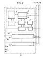
- FIG. 2 represents a group of stations Gi of FIG. 1, each comprising the device of the invention allowing the selection of a station from a group.
- Each station of the type known for example from published French application 2,513,470 "Group of terminal units for digital automatic branch exchange", includes a time channel extraction and injection circuit 2, a controller 3 which is a circuit transmission reception operating in HDLC procedure, a microprocessor 4, a memory 5, an exchange circuit 6, a group of terminals 7 and an interface circuit 8 connected to the clock signal link LSi, this circuit d interface distributing the clock and synchronization signals to the different organs of the station.
- each station S1 to Sk comprises an allocation device 9 connected to a self-allocation bus BA common to all the stations S1 to Sk of the group of stations Gi.
- the autoallocation bus BA is connected through a resistor R to the positive pole of a voltage source V whose negative pole is grounded.
- the allocation device 9 is connected to the microprocessor 4.
- FIG. 3 shows, by way of example, the diagram of the main station SP of the control unit UC of FIG. 1.
- An input circuit CE is connected by an incoming multiplex link 1a to the connection network RCX of the control unit UC, and an output circuit CS is connected by an outgoing multiplex link 1 to the connection network RCX of the control unit UC; the incoming 1a and outgoing multiplex links 1b constituting the bidirectional multiplex link 1 of FIG. 1.
- controllers C1 to C4 which are serial communication controllers, for example of the type 8530 marketed by AMD, are connected at the input by four incoming multiplex lines 25, 26, 27, 28, respectively, to the input circuit CE; they are also connected at output by four outgoing multiplex lines 29, 30, 31, 32, respectively, to the output circuit CS.
- the main station also includes a direct memory access circuit DMA, a memory M, a microprocessor MP and an interface circuit I.
- the microprocessor MP is connected by a data bus BD and through the interface circuit I, to the memory M, to the direct memory access circuit DMA, to the controllers Cl to C4, to the input circuit CE and to the output circuit CS; the microprocessor MP is also connected by a control bus BC to the controllers C1 to C4, to the direct memory access circuit DMA and to the memory M.
- Each controller is also connected to the direct memory access circuit DMA by a request link LD.
- the incoming multiplex link 1a is made up of several multiplex lines and the input circuit CE performs spatial and time switching between these multiplex lines and the incoming multiplex lines 25 to 28; similarly, the outgoing multiplex link 1b is made up of several multiplex lines and the output circuit CS performs spatial and temporal switching between the outgoing multiplex lines 29 to 32 and the multiplex lines of the outgoing multiplex link 1b.
- Messages from a station via the incoming multiplex link 1a are processed in one of the controllers C1 to C4, and messages to a group, or a station, are processed by one of the controllers C1 to C4 and sent on the outgoing multiplex link 1b.
- FIG. 4 represents the allocation device 9 of FIG. 2 which equips each station and comprises, an AND gate 16, a flip-flop 17, a resistor 18 and two transistors 19 and 20.
- the AND gate 16 is connected at output to the input of the flip-flop 17, type D, the output of which is connected by the resistor 18 to the base of the transistor 19.
- the transistor 19 has its collector connected to the self-allocation bus BA and its emitter connected to the collector of the transistor 20 whose transmitter is connected to ground; the collector of transistor 19 is also connected to an AND gate input 16 and by a bus status line 11 to the station microprocessor which is also connected by: a request line 12 to another input of the AND gate 16 , a release line 13 at a reset input of flip-flop 17, a status line 14 at the output of flip-flop 17, a blocking line 15 at the base of transistor 20.
- a station Si of a group Gi wishes to reserve the reserved channel of the transmission multiplex link
- its microprocessor 4 runs the algorithm shown in FIG. 5 to make an attempt to take the self-allocation bus by sending a signal on request line 12 at gate AND 16; this receives on an input a status signal from the bus of value 1 if the self-allocation bus BA is free and a signal of value 0 if the bus is busy. If another station has taken the bus, the AND gate is inhibited and the request is blocked at the AND gate. If the bus is free, the AND gate delivers a signal to flip-flop 17 which changes state and delivers a signal on the base of transistor 19, this signal rendering transistor 19 on.
- the transistor 20 normally receives by the blocking line 15 a control signal which turns it on; in the event of an internal failure of the station, the base of transistor 20 receives a signal which blocks transistor 20 which itself blocks transistor 19 since the two transistors are in series.
- the self-allocation bus BA is practically brought to ground through the collector-emitter junctions of the transistors 19 and 20
- the self-allocation bus being thus grounded, no other station in the group can take the self-allocation bus since the AND gate 16 of its allocation device is inhibited.
- the bus status is transmitted, by the bus status line 11, to the microprocessor which notices the change in the bus status, and which also receives by the line state 14 the state of the flip-flop 17 in order to confirm that the change of state of the bus does indeed result from the change of state of the flip-flop, therefore of the socket request sent on the request line 12.
- the microprocessor being thus informed that the change of state of the self-allocation bus results from its request for taking, will command the emission of the message on the multiplex link of emission Lib which connects the group to the main station, as soon as 'it will receive a consultation message from the main station via the Lia multiplex reception link.
- the consultation message is broadcast to all the stations, since these are linked to the reception multiplex link Lia, but only the station having taken the self-allocation bus BA will send a message on the multiplex link d 'Lib transmission, in the reserved channel of the frame of this multiplex link.
- the microprocessor delivers by the release line 13 a release signal which resets the flip-flop 17 to zero, which releases the self-allocation bus BA.
- the aim of the algorithm represented in FIG. 5 is to allocate to each of the stations in a frame of 125 microseconds, a determined time interval, depending on the address of the station in the group; the frame is delimited by the synchronization signal conveyed by the clock signal links LS1 to LSn. This time interval allocated to each station avoids conflicts between stations in a group, by allowing attempts to take the BA self-allocation bus from the group to be separated.
- the microprocessor When a station wants to transmit a message, the microprocessor unrolls the algorithm which begins by waiting for the passage of the synchronization signal; the first transition of the latter arms a delay initialized to Nt microseconds, N being the address of the station in the group, and t having a minimum value of 3 microseconds, imposed by the uncertainty introduced by the execution, by the microprocessor, of the waiting loop for the transition of the synchronization signal.
- Nt microseconds N being the address of the station in the group
- t having a minimum value of 3 microseconds, imposed by the uncertainty introduced by the execution, by the microprocessor, of the waiting loop for the transition of the synchronization signal.
- a request to take the self-allocation bus is made and the result, bus taken or not by the station, is verified (state of flip-flop 17 transmitted by status line 14 and state of the bus transmitted by the bus status line 11).
- the transmission multiplex link Lib is allocated to the station which will send its message upon receipt of the group consultation message sent by the main station.
- the consultation message is broadcast to all stations, but only the station that took the bus will be able to transmit, since in the other stations the socket request will have been negative, the microprocessor of each of them having been informed, via the status line of bus 11 and status line 14, of the failure of the request to take the self-allocation bus.
- a second time delay is armed at the end of which the process indicated above is repeated (waiting for transition of the synchronization signal, etc.). ).
Landscapes
- Engineering & Computer Science (AREA)
- Computer Networks & Wireless Communication (AREA)
- Signal Processing (AREA)
- Time-Division Multiplex Systems (AREA)
- Small-Scale Networks (AREA)
- Data Exchanges In Wide-Area Networks (AREA)
Claims (5)
Applications Claiming Priority (2)
| Application Number | Priority Date | Filing Date | Title |
|---|---|---|---|
| FR8315294A FR2552609B1 (fr) | 1983-09-27 | 1983-09-27 | Procede et dispositif de selection d'une station d'un ensemble de stations dialoguant avec une station principale |
| FR8315294 | 1983-09-27 |
Publications (2)
| Publication Number | Publication Date |
|---|---|
| EP0141241A1 EP0141241A1 (de) | 1985-05-15 |
| EP0141241B1 true EP0141241B1 (de) | 1988-05-18 |
Family
ID=9292556
Family Applications (1)
| Application Number | Title | Priority Date | Filing Date |
|---|---|---|---|
| EP84111397A Expired EP0141241B1 (de) | 1983-09-27 | 1984-09-25 | Verfahren und Anordnung zur Auswahl einer Station in einer Gruppe von Stationen im Dialog mit einer Hauptstation |
Country Status (12)
| Country | Link |
|---|---|
| US (1) | US4713805A (de) |
| EP (1) | EP0141241B1 (de) |
| JP (1) | JPS6094559A (de) |
| AU (1) | AU578427B2 (de) |
| CA (1) | CA1222080A (de) |
| DE (1) | DE3471417D1 (de) |
| FI (1) | FI83008C (de) |
| FR (1) | FR2552609B1 (de) |
| IE (1) | IE55732B1 (de) |
| IN (1) | IN160944B (de) |
| PL (1) | PL249774A1 (de) |
| ZA (1) | ZA847545B (de) |
Cited By (1)
| Publication number | Priority date | Publication date | Assignee | Title |
|---|---|---|---|---|
| US7585583B2 (en) | 2002-01-15 | 2009-09-08 | Nv Bekaert Sa | Metal stack for fuel cells or electrolysers |
Families Citing this family (11)
| Publication number | Priority date | Publication date | Assignee | Title |
|---|---|---|---|---|
| AU590236B2 (en) * | 1984-12-21 | 1989-11-02 | Sony Corporation | Communication system for video information apparatus |
| GB2193066B (en) * | 1986-07-07 | 1990-07-04 | Perkin Elmer Corp | Computer bus |
| US4787082A (en) * | 1986-07-24 | 1988-11-22 | American Telephone And Telegraph Company, At&T Bell Laboratories | Data flow control arrangement for local area network |
| US4789983A (en) * | 1987-03-05 | 1988-12-06 | American Telephone And Telegraph Company, At&T Bell Laboratories | Wireless network for wideband indoor communications |
| WO1991016775A1 (en) * | 1990-04-25 | 1991-10-31 | Telxon Corporation | Communication system with adaptive media access control |
| US5227778A (en) * | 1991-04-05 | 1993-07-13 | Digital Equipment Corporation | Service name to network address translation in communications network |
| US5291480A (en) * | 1991-06-18 | 1994-03-01 | Dsc Communications Corporation | Synchronous node controllers for switching network |
| US5642488A (en) * | 1994-05-23 | 1997-06-24 | American Airlines, Inc. | Method and apparatus for a host computer to stage a plurality of terminal addresses |
| US6119017A (en) * | 1997-11-25 | 2000-09-12 | Motorola, Inc. | Method of registration in a communication system |
| DE10112541A1 (de) * | 2001-03-15 | 2002-09-26 | Infineon Technologies Ag | Datenbusanordnung mit einem im Multiplexbetrieb betreibbaren Datenbus und Verfahren zum Betreiben dieser Anordnung |
| EP1327492A1 (de) * | 2002-01-15 | 2003-07-16 | N.V. Bekaert S.A. | Poröser Metallstapel für Brennstoffzellen oder Elektrolyseure |
Family Cites Families (14)
| Publication number | Priority date | Publication date | Assignee | Title |
|---|---|---|---|---|
| JPS5148845B2 (de) * | 1971-11-08 | 1976-12-23 | ||
| JPS5025256A (de) * | 1973-07-05 | 1975-03-17 | ||
| US3978451A (en) * | 1975-04-21 | 1976-08-31 | Rca Corporation | Controlling communications between computer devices over common bus |
| US4320502A (en) * | 1978-02-22 | 1982-03-16 | International Business Machines Corp. | Distributed priority resolution system |
| US4199662A (en) * | 1978-07-17 | 1980-04-22 | Lowe Charles S Jr | Hybrid control of time division multiplexing |
| JPS5951794B2 (ja) * | 1979-01-20 | 1984-12-15 | 日本電信電話株式会社 | 分散型電子交換機の制御方式 |
| US4232294A (en) * | 1979-04-30 | 1980-11-04 | Control Data Corporation | Method and apparatus for rotating priorities between stations sharing a communication channel |
| US4395710A (en) * | 1980-11-26 | 1983-07-26 | Westinghouse Electric Corp. | Bus access circuit for high speed digital data communication |
| ZA824685B (en) * | 1981-07-08 | 1983-04-27 | Int Computers Ltd | Data communication system |
| JPS58149531A (ja) * | 1982-03-01 | 1983-09-05 | Yokogawa Hokushin Electric Corp | バス使用権制御方法 |
| EP0096097B1 (de) * | 1982-06-15 | 1985-12-27 | International Business Machines Corporation | Verfahren und Einrichtung zum Kontrollieren des Zugriffs auf ein Nachrichtennetzwerk |
| FR2535140B1 (fr) * | 1982-10-26 | 1988-02-05 | Thomson Csf Mat Tel | Autocommutateur electronique temporel numerique mic a architecture decentralisee |
| EP0109964B1 (de) * | 1982-11-26 | 1986-04-23 | International Business Machines Corporation | Synchronisierung in einem Nachrichtennetz aus miteinander verbundenen Ringen |
| US4550402A (en) * | 1983-12-22 | 1985-10-29 | Ford Motor Company | Data communication system |
-
1983
- 1983-09-27 FR FR8315294A patent/FR2552609B1/fr not_active Expired
-
1984
- 1984-02-06 IN IN107/DEL/84A patent/IN160944B/en unknown
- 1984-09-20 US US06/652,390 patent/US4713805A/en not_active Expired - Fee Related
- 1984-09-24 FI FI843736A patent/FI83008C/fi not_active IP Right Cessation
- 1984-09-25 EP EP84111397A patent/EP0141241B1/de not_active Expired
- 1984-09-25 ZA ZA847545A patent/ZA847545B/xx unknown
- 1984-09-25 DE DE8484111397T patent/DE3471417D1/de not_active Expired
- 1984-09-26 AU AU33551/84A patent/AU578427B2/en not_active Ceased
- 1984-09-26 IE IE2452/84A patent/IE55732B1/en not_active IP Right Cessation
- 1984-09-26 CA CA000464097A patent/CA1222080A/fr not_active Expired
- 1984-09-27 PL PL24977484A patent/PL249774A1/xx unknown
- 1984-09-27 JP JP59202861A patent/JPS6094559A/ja active Pending
Cited By (1)
| Publication number | Priority date | Publication date | Assignee | Title |
|---|---|---|---|---|
| US7585583B2 (en) | 2002-01-15 | 2009-09-08 | Nv Bekaert Sa | Metal stack for fuel cells or electrolysers |
Also Published As
| Publication number | Publication date |
|---|---|
| AU3355184A (en) | 1985-04-04 |
| IE55732B1 (en) | 1991-01-02 |
| EP0141241A1 (de) | 1985-05-15 |
| US4713805A (en) | 1987-12-15 |
| AU578427B2 (en) | 1988-10-27 |
| PL249774A1 (en) | 1985-06-04 |
| DE3471417D1 (en) | 1988-06-23 |
| FI83008C (fi) | 1991-05-10 |
| IE842452L (en) | 1985-03-27 |
| FI843736L (fi) | 1985-03-28 |
| ZA847545B (en) | 1985-05-29 |
| IN160944B (de) | 1987-08-15 |
| JPS6094559A (ja) | 1985-05-27 |
| FI843736A0 (fi) | 1984-09-24 |
| FR2552609A1 (fr) | 1985-03-29 |
| FR2552609B1 (fr) | 1985-10-25 |
| CA1222080A (fr) | 1987-05-19 |
| FI83008B (fi) | 1991-01-31 |
Similar Documents
| Publication | Publication Date | Title |
|---|---|---|
| US4630254A (en) | Controlled star network | |
| US4661952A (en) | Method for transmitting data in a telecommunications exchange | |
| US4817082A (en) | Crosspoint switching system using control rings with fast token circulation | |
| CA1237187A (en) | Wide band integrated services local communication system | |
| EP0141241B1 (de) | Verfahren und Anordnung zur Auswahl einer Station in einer Gruppe von Stationen im Dialog mit einer Hauptstation | |
| US4383315A (en) | Idle time slot seizure and transmission facilities for loop communication system | |
| EP0517609B1 (de) | Verfahren und Arbitrierungsbus zur Übertragung von seriellen Daten | |
| US4538263A (en) | Variable-band switching system for voice and data communication | |
| EP0505779A2 (de) | Schaltvorrichtung mit doppelter Priorität für Simplex-Netzwerke | |
| US4706150A (en) | Switching protocal for multiple autonomous switching planes | |
| WO1999014915A2 (en) | Process scheduling in computer network | |
| Mark | Distributed scheduling conflict-free multiple access for local area communication networks | |
| EP0255442A2 (de) | Schaltungsanordnung zur Ausführung des Zugriffsprotokolls zum seriellen Austausch von Informationen zwischen durch ein fiberoptisches Sternnetz verbundenen Endgeräten | |
| US5383186A (en) | Apparatus and method for synchronous traffic bandwidth on a token ring network | |
| EP0200275A1 (de) | Multiplex-Nachrichtenübertragungssystem | |
| EP0376249B1 (de) | Deblockierverfahren eines Multiprozessor-Multibus-Systems | |
| EP0899984A1 (de) | Verfahren zur Ausbeutung einer von mehreren Einheiten temporal verteilten Übertragungsstrecke und Einheit zur Durchführung eines solchen Verfahrens | |
| US6654838B1 (en) | Methods for performing bit sensitive parallel bus peer addressing | |
| JPH03270432A (ja) | ローカル・エリア・ネットワーク | |
| US5271008A (en) | Unidirectional bus system using reset signal | |
| EP0269423A2 (de) | Lokales Netzwerk | |
| CA2013644A1 (fr) | Procede et dispositif d'acces a un medium de communication partage entre des utilisateurs pouvant transmettre en mode circuit ou paquet avec differents niveaux de priorite | |
| Suda et al. | Tree LANs with collision avoidance: protocol, switch architecture, and simulated performance | |
| BE888019R (fr) | Montage de transmission de donnees | |
| RU2068579C1 (ru) | Способ доступа абонента к шине данных в вычислительной сети ethernet и устройство для его осуществления |
Legal Events
| Date | Code | Title | Description |
|---|---|---|---|
| PUAI | Public reference made under article 153(3) epc to a published international application that has entered the european phase |
Free format text: ORIGINAL CODE: 0009012 |
|
| AK | Designated contracting states |
Designated state(s): BE CH DE FR GB IT LI NL SE |
|
| 17P | Request for examination filed |
Effective date: 19851029 |
|
| RAP1 | Party data changed (applicant data changed or rights of an application transferred) |
Owner name: ALCATEL |
|
| 17Q | First examination report despatched |
Effective date: 19861218 |
|
| RAP1 | Party data changed (applicant data changed or rights of an application transferred) |
Owner name: ALCATEL CIT |
|
| GRAA | (expected) grant |
Free format text: ORIGINAL CODE: 0009210 |
|
| AK | Designated contracting states |
Kind code of ref document: B1 Designated state(s): BE CH DE FR GB IT LI NL SE |
|
| REF | Corresponds to: |
Ref document number: 3471417 Country of ref document: DE Date of ref document: 19880623 |
|
| ITF | It: translation for a ep patent filed | ||
| GBT | Gb: translation of ep patent filed (gb section 77(6)(a)/1977) | ||
| PLBE | No opposition filed within time limit |
Free format text: ORIGINAL CODE: 0009261 |
|
| STAA | Information on the status of an ep patent application or granted ep patent |
Free format text: STATUS: NO OPPOSITION FILED WITHIN TIME LIMIT |
|
| 26N | No opposition filed | ||
| ITTA | It: last paid annual fee | ||
| EAL | Se: european patent in force in sweden |
Ref document number: 84111397.0 |
|
| PGFP | Annual fee paid to national office [announced via postgrant information from national office to epo] |
Ref country code: GB Payment date: 19980814 Year of fee payment: 15 |
|
| PGFP | Annual fee paid to national office [announced via postgrant information from national office to epo] |
Ref country code: FR Payment date: 19980821 Year of fee payment: 15 Ref country code: DE Payment date: 19980821 Year of fee payment: 15 |
|
| PGFP | Annual fee paid to national office [announced via postgrant information from national office to epo] |
Ref country code: SE Payment date: 19980824 Year of fee payment: 15 Ref country code: CH Payment date: 19980824 Year of fee payment: 15 |
|
| PGFP | Annual fee paid to national office [announced via postgrant information from national office to epo] |
Ref country code: NL Payment date: 19980827 Year of fee payment: 15 |
|
| PGFP | Annual fee paid to national office [announced via postgrant information from national office to epo] |
Ref country code: BE Payment date: 19980908 Year of fee payment: 15 |
|
| PG25 | Lapsed in a contracting state [announced via postgrant information from national office to epo] |
Ref country code: GB Free format text: LAPSE BECAUSE OF NON-PAYMENT OF DUE FEES Effective date: 19990925 |
|
| PG25 | Lapsed in a contracting state [announced via postgrant information from national office to epo] |
Ref country code: SE Free format text: THE PATENT HAS BEEN ANNULLED BY A DECISION OF A NATIONAL AUTHORITY Effective date: 19990929 |
|
| PG25 | Lapsed in a contracting state [announced via postgrant information from national office to epo] |
Ref country code: LI Free format text: LAPSE BECAUSE OF NON-PAYMENT OF DUE FEES Effective date: 19990930 Ref country code: CH Free format text: LAPSE BECAUSE OF NON-PAYMENT OF DUE FEES Effective date: 19990930 Ref country code: BE Free format text: LAPSE BECAUSE OF NON-PAYMENT OF DUE FEES Effective date: 19990930 |
|
| BERE | Be: lapsed |
Owner name: ALCATEL CIT Effective date: 19990930 |
|
| PG25 | Lapsed in a contracting state [announced via postgrant information from national office to epo] |
Ref country code: NL Free format text: LAPSE BECAUSE OF NON-PAYMENT OF DUE FEES Effective date: 20000401 |
|
| EUG | Se: european patent has lapsed |
Ref document number: 84111397.0 |
|
| REG | Reference to a national code |
Ref country code: CH Ref legal event code: PL |
|
| GBPC | Gb: european patent ceased through non-payment of renewal fee |
Effective date: 19990925 |
|
| PG25 | Lapsed in a contracting state [announced via postgrant information from national office to epo] |
Ref country code: FR Free format text: LAPSE BECAUSE OF NON-PAYMENT OF DUE FEES Effective date: 20000531 |
|
| NLV4 | Nl: lapsed or anulled due to non-payment of the annual fee |
Effective date: 20000401 |
|
| PG25 | Lapsed in a contracting state [announced via postgrant information from national office to epo] |
Ref country code: DE Free format text: LAPSE BECAUSE OF NON-PAYMENT OF DUE FEES Effective date: 20000701 |
|
| REG | Reference to a national code |
Ref country code: FR Ref legal event code: ST |