DE202021104723U1 - Image projector coupled to an optical light guide element - Google Patents
Image projector coupled to an optical light guide element Download PDFInfo
- Publication number
- DE202021104723U1 DE202021104723U1 DE202021104723.2U DE202021104723U DE202021104723U1 DE 202021104723 U1 DE202021104723 U1 DE 202021104723U1 DE 202021104723 U DE202021104723 U DE 202021104723U DE 202021104723 U1 DE202021104723 U1 DE 202021104723U1
- Authority
- DE
- Germany
- Prior art keywords
- slm
- loe
- illumination
- image
- optical system
- Prior art date
- Legal status (The legal status is an assumption and is not a legal conclusion. Google has not performed a legal analysis and makes no representation as to the accuracy of the status listed.)
- Active
Links
- 230000003287 optical effect Effects 0.000 title claims abstract description 31
- 238000005286 illumination Methods 0.000 claims abstract description 37
- 230000008878 coupling Effects 0.000 claims abstract description 22
- 238000010168 coupling process Methods 0.000 claims abstract description 22
- 238000005859 coupling reaction Methods 0.000 claims abstract description 22
- 238000003384 imaging method Methods 0.000 claims abstract description 6
- XUIMIQQOPSSXEZ-UHFFFAOYSA-N Silicon Chemical compound [Si] XUIMIQQOPSSXEZ-UHFFFAOYSA-N 0.000 claims description 3
- 239000004973 liquid crystal related substance Substances 0.000 claims description 3
- 229910052710 silicon Inorganic materials 0.000 claims description 3
- 239000010703 silicon Substances 0.000 claims description 3
- 239000000758 substrate Substances 0.000 description 8
- 230000007246 mechanism Effects 0.000 description 2
- 238000000576 coating method Methods 0.000 description 1
- 239000003086 colorant Substances 0.000 description 1
- 210000005069 ears Anatomy 0.000 description 1
- 239000013307 optical fiber Substances 0.000 description 1
- 230000010287 polarization Effects 0.000 description 1
- 238000000926 separation method Methods 0.000 description 1
Images


Classifications
-
- G—PHYSICS
- G02—OPTICS
- G02B—OPTICAL ELEMENTS, SYSTEMS OR APPARATUS
- G02B27/00—Optical systems or apparatus not provided for by any of the groups G02B1/00 - G02B26/00, G02B30/00
- G02B27/01—Head-up displays
- G02B27/017—Head mounted
- G02B27/0172—Head mounted characterised by optical features
-
- G—PHYSICS
- G02—OPTICS
- G02B—OPTICAL ELEMENTS, SYSTEMS OR APPARATUS
- G02B27/00—Optical systems or apparatus not provided for by any of the groups G02B1/00 - G02B26/00, G02B30/00
- G02B27/28—Optical systems or apparatus not provided for by any of the groups G02B1/00 - G02B26/00, G02B30/00 for polarising
- G02B27/283—Optical systems or apparatus not provided for by any of the groups G02B1/00 - G02B26/00, G02B30/00 for polarising used for beam splitting or combining
-
- G—PHYSICS
- G02—OPTICS
- G02B—OPTICAL ELEMENTS, SYSTEMS OR APPARATUS
- G02B27/00—Optical systems or apparatus not provided for by any of the groups G02B1/00 - G02B26/00, G02B30/00
- G02B27/30—Collimators
-
- G—PHYSICS
- G02—OPTICS
- G02B—OPTICAL ELEMENTS, SYSTEMS OR APPARATUS
- G02B6/00—Light guides; Structural details of arrangements comprising light guides and other optical elements, e.g. couplings
- G02B6/0001—Light guides; Structural details of arrangements comprising light guides and other optical elements, e.g. couplings specially adapted for lighting devices or systems
- G02B6/0011—Light guides; Structural details of arrangements comprising light guides and other optical elements, e.g. couplings specially adapted for lighting devices or systems the light guides being planar or of plate-like form
- G02B6/0013—Means for improving the coupling-in of light from the light source into the light guide
- G02B6/0015—Means for improving the coupling-in of light from the light source into the light guide provided on the surface of the light guide or in the bulk of it
- G02B6/0018—Redirecting means on the surface of the light guide
-
- G—PHYSICS
- G02—OPTICS
- G02B—OPTICAL ELEMENTS, SYSTEMS OR APPARATUS
- G02B6/00—Light guides; Structural details of arrangements comprising light guides and other optical elements, e.g. couplings
- G02B6/0001—Light guides; Structural details of arrangements comprising light guides and other optical elements, e.g. couplings specially adapted for lighting devices or systems
- G02B6/0011—Light guides; Structural details of arrangements comprising light guides and other optical elements, e.g. couplings specially adapted for lighting devices or systems the light guides being planar or of plate-like form
- G02B6/0013—Means for improving the coupling-in of light from the light source into the light guide
- G02B6/0015—Means for improving the coupling-in of light from the light source into the light guide provided on the surface of the light guide or in the bulk of it
- G02B6/002—Means for improving the coupling-in of light from the light source into the light guide provided on the surface of the light guide or in the bulk of it by shaping at least a portion of the light guide, e.g. with collimating, focussing or diverging surfaces
-
- G—PHYSICS
- G02—OPTICS
- G02B—OPTICAL ELEMENTS, SYSTEMS OR APPARATUS
- G02B6/00—Light guides; Structural details of arrangements comprising light guides and other optical elements, e.g. couplings
- G02B6/0001—Light guides; Structural details of arrangements comprising light guides and other optical elements, e.g. couplings specially adapted for lighting devices or systems
- G02B6/0011—Light guides; Structural details of arrangements comprising light guides and other optical elements, e.g. couplings specially adapted for lighting devices or systems the light guides being planar or of plate-like form
- G02B6/0013—Means for improving the coupling-in of light from the light source into the light guide
- G02B6/0023—Means for improving the coupling-in of light from the light source into the light guide provided by one optical element, or plurality thereof, placed between the light guide and the light source, or around the light source
- G02B6/0026—Wavelength selective element, sheet or layer, e.g. filter or grating
-
- H—ELECTRICITY
- H04—ELECTRIC COMMUNICATION TECHNIQUE
- H04N—PICTORIAL COMMUNICATION, e.g. TELEVISION
- H04N9/00—Details of colour television systems
- H04N9/12—Picture reproducers
- H04N9/31—Projection devices for colour picture display, e.g. using electronic spatial light modulators [ESLM]
- H04N9/3102—Projection devices for colour picture display, e.g. using electronic spatial light modulators [ESLM] using two-dimensional electronic spatial light modulators
-
- H—ELECTRICITY
- H04—ELECTRIC COMMUNICATION TECHNIQUE
- H04N—PICTORIAL COMMUNICATION, e.g. TELEVISION
- H04N9/00—Details of colour television systems
- H04N9/12—Picture reproducers
- H04N9/31—Projection devices for colour picture display, e.g. using electronic spatial light modulators [ESLM]
- H04N9/3141—Constructional details thereof
- H04N9/315—Modulator illumination systems
- H04N9/3152—Modulator illumination systems for shaping the light beam
-
- G—PHYSICS
- G02—OPTICS
- G02B—OPTICAL ELEMENTS, SYSTEMS OR APPARATUS
- G02B27/00—Optical systems or apparatus not provided for by any of the groups G02B1/00 - G02B26/00, G02B30/00
- G02B27/01—Head-up displays
- G02B27/017—Head mounted
- G02B2027/0178—Eyeglass type
Landscapes
- Physics & Mathematics (AREA)
- General Physics & Mathematics (AREA)
- Optics & Photonics (AREA)
- Engineering & Computer Science (AREA)
- Multimedia (AREA)
- Signal Processing (AREA)
- Projection Apparatus (AREA)
Abstract
Optisches System, umfassend:
(a) ein optisches Lichtleiterelement (LOE) mit einem Paar paralleler Hauptaußenflächen zum Leiten von Abbildungslicht durch interne Reflexion an den Hauptaußenflächen, wobei das LOE eine seitliche Einkoppelfläche aufweist; und
(b) einen Bildprojektor, umfassend ein Prisma mit:
(i) einer ersten Oberfläche, die einer Beleuchtungsanordnung zugeordnet ist;
(ii) einer zweiten Oberfläche, die einem reflektierenden räumlichen Lichtmodulator (SLM) zugeordnet ist;
(iii) einer dritten Oberfläche mit einer Viertelwellenplatte und einer reflektierenden Kollimationslinse;
(iv) einer vierten Oberfläche, die optisch mit der Einkoppelfläche des LOE gekoppelt ist;
(v) einem polarisierenden Strahlteiler (PBS), der innerhalb des Prismas angeordnet ist, um einen Lichtweg zu definieren, derart, dass Beleuchtung von der Beleuchtungsanordnung den SLM beleuchtet, und derart, dass reflektierte Bildbeleuchtung von dem SLM durch die Kollimationslinse kollimiert und auf die Einkoppelfläche gerichtet wird; und
(vi) einer fünften Oberfläche, die nicht parallel zu allen der ersten, zweiten, dritten und vierten Oberflächen ist, wobei die fünfte Oberfläche koplanar und optisch durchgehend mit einer der Hauptaußenflächen des LOE ist, wobei ein Teil der durch die Kollimationslinse kollimierten Bildbeleuchtung an der fünften Oberfläche intern reflektiert wird, bevor sie die Einkoppelfläche erreicht.
(A) an optical light guide element (LOE) with a pair of parallel main outer surfaces for guiding imaging light by internal reflection on the main outer surfaces, the LOE having a lateral coupling-in surface; and
(b) an image projector comprising a prism having:
(i) a first surface associated with a lighting arrangement;
(ii) a second surface associated with a reflective spatial light modulator (SLM);
(iii) a third surface having a quarter wave plate and a reflective collimating lens;
(iv) a fourth surface which is optically coupled to the coupling surface of the LOE;
(v) a polarizing beam splitter (PBS) disposed within the prism to define a light path such that illumination from the illumination assembly illuminates the SLM and such that reflected image illumination from the SLM collimates through the collimation lens and onto the Coupling surface is directed; and
(vi) a fifth surface that is not parallel to all of the first, second, third, and fourth surfaces, the fifth surface being coplanar and optically continuous with one of the major exterior surfaces of the LOE, with a portion of the image illumination collimated by the collimating lens on the fifth Surface is internally reflected before it reaches the coupling surface.
Description
GEBIET UND HINTERGRUND DER ERFINDUNGFIELD AND BACKGROUND OF THE INVENTION
Die vorliegende Erfindung bezieht sich auf optische Systeme und betrifft insbesondere einen Bildprojektor, der mit einem optischen Lichtleiterelement (LOE) als Teil eines Anzeigesystems gekoppelt ist.The present invention relates to optical systems, and more particularly relates to an image projector that is coupled to an optical light guide element (LOE) as part of a display system.
Viele augennahe Anzeigesysteme enthalten ein transparentes optisches Lichtleiterelement (LOE) oder einen „Wellenleiter“, das bzw. der vor dem Auge des Benutzers platziert wird, das durch interne Reflexion ein Bild innerhalb des LOE überträgt und dann eine optische Aperturausweitung in einer oder zwei Dimensionen erreicht und das Bild durch einen geeigneten Auskoppelmechanismus in Richtung des Auges des Benutzers auskoppelt. Die Aperturausweitungs- und Auskoppelmechanismen können auf eingebetteten Teilreflektoren oder „Facetten“ basieren oder können beugungsoptische Elemente verwenden.Many near-eye display systems incorporate a transparent optical light guide element (LOE) or "waveguide" placed in front of the user's eye that, by internal reflection, transmits an image within the LOE and then achieves an optical aperture expansion in one or two dimensions and the image decouples in the direction of the user's eye by a suitable decoupling mechanism. The aperture widening and decoupling mechanisms can be based on embedded partial reflectors or "facets" or can use diffraction optical elements.
KURZDARSTELLUNG DER ERFINDUNGSUMMARY OF THE INVENTION
Die vorliegende Erfindung ist ein optisches System.The present invention is an optical system.
Gemäß den Lehren einer Ausführungsform der vorliegenden Erfindung wird ein optisches System bereitgestellt, umfassend: (a) ein optisches Lichtleiterelement (LOE) mit einem Paar paralleler Hauptaußenflächen zum Leiten von Abbildungslicht durch interne Reflexion an den Hauptaußenflächen, wobei das LOE eine seitliche Einkoppelfläche aufweist; und (b) einen Bildprojektor umfassend ein Prisma mit:
- (i) einer ersten Oberfläche, die einer Beleuchtungsanordnung zugeordnet ist; (ii) einer zweiten Oberfläche, die einem reflektierenden räumlichen Lichtmodulator (SLM) zugeordnet ist; (iii) einer dritten Oberfläche mit einer Viertelwellenplatte und einer reflektierenden Kollimationslinse; (iv) einer vierten Oberfläche, die optisch mit der Einkoppelfläche des LOE gekoppelt ist; (v) einem polarisierenden Strahlteiler (PBS), der innerhalb des Prismas so angeordnet ist, dass er einen Lichtweg definiert, derart, dass Beleuchtung von der Beleuchtungsanordnung den SLM beleuchtet und derart, dass reflektierte Bildbeleuchtung von dem SLM durch die Kollimationslinse kollimiert und auf die Einkoppelfläche gerichtet wird; und (vi) einer fünften Oberfläche, die nicht parallel zu allen der ersten, zweiten, dritten und vierten Oberfläche ist, wobei die fünfte Oberfläche koplanar und optisch durchgehend mit einer der Hauptaußenflächen des LOE ist, wobei ein Teil der durch die Kollimationslinse kollimierten Bildbeleuchtung an der fünften Oberfläche intern reflektiert wird, bevor sie die Einkoppelfläche erreicht.
- (i) a first surface associated with a lighting arrangement; (ii) a second surface associated with a reflective spatial light modulator (SLM); (iii) a third surface having a quarter wave plate and a reflective collimating lens; (iv) a fourth surface which is optically coupled to the coupling surface of the LOE; (v) a polarizing beam splitter (PBS) positioned within the prism to define a light path such that illumination from the lighting assembly illuminates the SLM and such that reflected image illumination from the SLM collimates through the collimation lens and onto the Coupling surface is directed; and (vi) a fifth surface that is not parallel to all of the first, second, third and fourth surfaces, the fifth surface being coplanar and optically continuous with one of the major exterior surfaces of the LOE, with a portion of the image illumination collimated by the collimating lens on the fifth surface is internally reflected before it reaches the coupling surface.
Gemäß einem weiteren Merkmal einer Ausführungsform der vorliegenden Erfindung wird der PBS dazu eingesetzt, Beleuchtung von der Beleuchtungsanordnung zum SLM zu reflektieren, reflektierte Bildbeleuchtung, die vom SLM reflektiert wird, zur Kollimationslinse zu übertragen, und kollimierte Bildbeleuchtung von der Kollimationslinse zur Einkoppelfläche zu reflektieren.According to a further feature of an embodiment of the present invention, the PBS is used to reflect lighting from the lighting arrangement to the SLM, to transmit reflected image lighting that is reflected from the SLM to the collimation lens, and to reflect collimated image lighting from the collimation lens to the coupling surface.
Gemäß einem weiteren Merkmal einer Ausführungsform der vorliegenden Erfindung sind die zweite Oberfläche und die dritte Oberfläche schräg zur fünften Oberfläche abgewinkelt.According to a further feature of an embodiment of the present invention, the second surface and the third surface are angled obliquely to the fifth surface.
Gemäß einem weiteren Merkmal einer Ausführungsform der vorliegenden Erfindung ist die zweite Oberfläche parallel zur dritten Oberfläche.According to a further feature of an embodiment of the present invention, the second surface is parallel to the third surface.
Gemäß einem weiteren Merkmal einer Ausführungsform der vorliegenden Erfindung bildet die dritte Oberfläche mit der fünften Oberfläche einen Winkel zwischen 50 Grad und 70 Grad.According to a further feature of an embodiment of the present invention, the third surface forms an angle between 50 degrees and 70 degrees with the fifth surface.
Gemäß einem weiteren Merkmal einer Ausführungsform der vorliegenden Erfindung ist der SLM ein Flüssigkristall-auf-Silizium-(LCOS)-Chip.In accordance with a further feature of an embodiment of the present invention, the SLM is a liquid crystal on silicon (LCOS) chip.
Gemäß einem weiteren Merkmal einer Ausführungsform der vorliegenden Erfindung wird der PBS dazu eingesetzt, Beleuchtung von der Beleuchtungsanordnung zum SLM zu übertragen, reflektierte Bildbeleuchtung vom SLM zur Kollimationslinse zu reflektieren, und kollimierte Bildbeleuchtung von der Kollimationslinse zur Einkoppelfläche zu übertragen.According to a further feature of an embodiment of the present invention, the PBS is used to transmit illumination from the lighting arrangement to the SLM, to reflect reflected image illumination from the SLM to the collimation lens, and to transmit collimated image illumination from the collimation lens to the coupling surface.
FigurenlisteFigure list
Die Erfindung wird in diesem Schriftstück nur beispielhaft, unter Bezugnahme auf die Begleitzeichnungen, beschrieben, wobei:
-
1A und1B schematische isometrische Ansichten eines optischen Systems sind, das unter Verwendung eines optischen Lichtleiterelements (LOE) implementiert ist, das gemäß den Lehren der vorliegenden Erfindung konstruiert und betrieben wird und eine Top-Down- und eine seitliche Einspeisungskonfiguration darstellt; -
2 eine schematische Vorderansicht einer Implementierung des LOE von1A ist und die Positionierung eines mit dem LOE gekoppelten Bildprojektors zeigt; -
3 eine schematische vergrößerte isometrische Ansicht des Bildprojektors von2 ist; -
4 eine Seitenansicht des Bildprojektors von3 ist; -
5 eine schematische Querschnittsansicht entlang der Linie V-V in4 ist; -
6 eine Seitenansicht einer alternativen Implementierung des Bildprojektors von2 ist; und -
7 eine schematische Querschnittsansicht entlang der Linie VII-VII in6 ist.
-
1A and1B Figure 12 are schematic isometric views of an optical system implemented using a light guide element (LOE) constructed and operated in accordance with the teachings of the present invention showing top-down and side-feed configurations; -
2 FIG. 3 is a schematic front view of an implementation of the LOE of FIG1A and shows the positioning of an image projector coupled to the LOE; -
3 FIG. 3 is a schematic enlarged isometric view of the image projector of FIG2 is; -
4th a side view of the image projector of FIG3 is; -
5 a schematic cross-sectional view along the line VV in FIG4th is; -
6th FIG. 8 is a side view of an alternative implementation of the image projector of FIG2 is; and -
7th a schematic cross-sectional view along the line VII-VII in6th is.
BESCHREIBUNG DER BEVORZUGTEN AUSFÜHRUNGSFORMENDESCRIPTION OF THE PREFERRED EMBODIMENTS
Bestimmte Ausführungsformen der vorliegenden Erfindung stellen ein optisches System bereit, das einen mit einem optischen Lichtleiterelement (LOE) gekoppelten Bildprojektor enthält.Certain embodiments of the present invention provide an optical system that includes an image projector coupled to an optical fiber element (LOE).
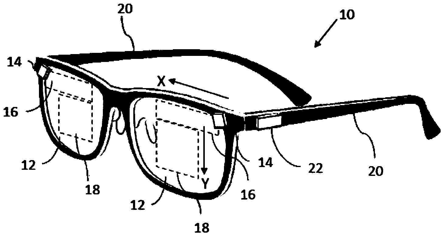
Eine beispielhafte Implementierung einer Vorrichtung in Form einer augennahen Anzeige, allgemein mit 10 bezeichnet, die ein LOE
Das LOE enthält typischerweise eine Anordnung zum Ausweiten der optischen Apertur des eingespeisten Bildes in eine oder zwei Dimensionen und zum Auskoppeln der Bildbeleuchtung in Richtung des Auges des Betrachters, typischerweise basierend entweder auf der Verwendung von internen teilreflektierenden Oberflächen oder auf beugungsoptischen Elementen. In einem nicht einschränkenden Satz von Implementierungen, der weiter schematisch in
Der erste Satz von teilweise reflektierenden Oberflächen lenkt die Bildbeleuchtung von einer ersten Ausbreitungsrichtung, die durch interne Totalreflexion (TIR) innerhalb des Substrats eingefangen wird, in eine zweite Ausbreitungsrichtung ab, die ebenfalls durch TIR innerhalb des Substrats eingefangen wird.The first set of partially reflective surfaces divert the image illumination from a first direction of propagation, which is captured by total internal reflection (TIR) within the substrate, to a second direction of propagation, which is also captured by TIR within the substrate.
Die abgelenkte Bildbeleuchtung gelangt dann in eine zweite Substratregion
In den Zeichnungen und Ansprüchen wird hierin Bezug genommen auf eine X-Achse, die sich horizontal (
Nur sehr näherungsweise kann davon ausgegangen werden, dass das erste LOE oder die erste Region
Es versteht sich, dass die augennahe Anzeige
Die Lehren der vorliegenden Erfindung beziehen sich hauptsächlich auf die Implementierung des Bildprojektors
Ein Implementierungsbildprojektor
Die Minimierung der optischen Größe für einen Bildprojektor basierend auf einem räumlichen Lichtmodulator (SLM), wie beispielsweise einem Flüssigkristall-auf-Silizium-(LCOS)-Chip, beinhaltet die Kombination von drei Funktionen:
- 1. Beleuchten des LCOS
- 2. Kollimieren des vom LCOS reflektierten Bildes
- 3. Kombinieren des Koppelprismas in den Wellenleiter
- 1. Illuminate the LCOS
- 2. Collimate the image reflected by the LCOS
- 3. Combining the coupling prism into the waveguide
Das Kombinieren aller vorstehend genannten Funktionen ist eine besondere Herausforderung, wenn eine kurze Brennweite für die Bildkollimation benötigt wird.
Die Draufsicht von
Somit verwendet der hier veranschaulichte Bildprojektor
Das Prisma des Bildprojektors
In der hier veranschaulichten Implementierung wird der PBS
Die Beleuchtungsquelle
Wie am besten in
Insbesondere, wie am besten in
Im Übrigen sind der Aufbau und die Funktionsweise der Implementierung der
Es wird hervorgehoben, dass die vorstehenden Beschreibungen nur als Beispiel dienen und dass zahlreiche weitere Ausführungsformen im Rahmen der vorliegenden Erfindung, wie sie in den beigefügten Ansprüchen definiert ist, möglich sind.It is emphasized that the above descriptions only serve as an example and that numerous other embodiments are possible within the scope of the present invention, as it is defined in the appended claims.
Claims (7)
Applications Claiming Priority (2)
| Application Number | Priority Date | Filing Date | Title |
|---|---|---|---|
| US202063076971P | 2020-09-11 | 2020-09-11 | |
| US63/076,971 | 2020-09-11 |
Publications (1)
| Publication Number | Publication Date |
|---|---|
| DE202021104723U1 true DE202021104723U1 (en) | 2021-10-18 |
Family
ID=78408929
Family Applications (1)
| Application Number | Title | Priority Date | Filing Date |
|---|---|---|---|
| DE202021104723.2U Active DE202021104723U1 (en) | 2020-09-11 | 2021-09-02 | Image projector coupled to an optical light guide element |
Country Status (6)
| Country | Link |
|---|---|
| US (1) | US11644676B2 (en) |
| JP (1) | JP3235064U (en) |
| KR (1) | KR20220000645U (en) |
| CN (1) | CN216118212U (en) |
| DE (1) | DE202021104723U1 (en) |
| TW (1) | TWM623587U (en) |
Cited By (1)
| Publication number | Priority date | Publication date | Assignee | Title |
|---|---|---|---|---|
| DE102022134420A1 (en) | 2022-12-21 | 2024-06-27 | OQmented GmbH | Device for generating and displaying an image on an observation field using a refractive waveguide |
Families Citing this family (5)
| Publication number | Priority date | Publication date | Assignee | Title |
|---|---|---|---|---|
| BR112022009872A2 (en) | 2019-12-05 | 2022-08-09 | Lumus Ltd | OPTICAL DEVICE AND METHOD TO MANUFACTURE AN OPTICAL DEVICE |
| EP4462172A3 (en) * | 2021-03-01 | 2025-01-22 | Lumus Ltd. | Optical system with compact coupling from a projector into a waveguide |
| IL313871A (en) | 2022-01-07 | 2024-08-01 | Lumus Ltd | Optical system for directing an image for viewing |
| CN116909051B (en) * | 2022-11-25 | 2024-07-16 | 剑芯光电(苏州)有限公司 | Polarization insensitive silicon-based liquid crystal device |
| WO2025203021A1 (en) * | 2024-03-24 | 2025-10-02 | Lumus Ltd. | Ghost reduction in near-eye displays |
Family Cites Families (258)
| Publication number | Priority date | Publication date | Assignee | Title |
|---|---|---|---|---|
| US2748659A (en) | 1951-02-26 | 1956-06-05 | Jenaer Glaswerk Schott & Gen | Light source, searchlight or the like for polarized light |
| US2886911A (en) | 1953-07-23 | 1959-05-19 | George K C Hardesty | Duo-panel edge illumination system |
| US2795069A (en) | 1956-02-07 | 1957-06-11 | George K C Hardesty | Laminated metal-plastic illuminable panel |
| DE1422172B1 (en) | 1961-12-07 | 1970-11-12 | Kopperschmidt & Co Carl W | periscope |
| US3491245A (en) | 1967-04-10 | 1970-01-20 | George K C Hardesty | Guided light display panel |
| DE2057827A1 (en) | 1969-11-24 | 1971-06-03 | Vickers Ltd | Optical arrangement for flattening the image field |
| US3626394A (en) | 1970-04-09 | 1971-12-07 | Magnavox Co | Magneto-optical system |
| US3667621A (en) | 1970-10-20 | 1972-06-06 | Wisconsin Foundry And Machine | Fluid power system for a self-contained unloading unit |
| US3737212A (en) | 1970-12-14 | 1973-06-05 | Gen Electric | Diffraction optics head up display |
| GB1377627A (en) | 1971-09-01 | 1974-12-18 | Rank Organisation Ltd | Beam splitting prisms |
| US3857109A (en) | 1973-11-21 | 1974-12-24 | Us Navy | Longitudinally-pumped two-wavelength lasers |
| US3873209A (en) | 1973-12-10 | 1975-03-25 | Bell Telephone Labor Inc | Measurement of thin films by optical waveguiding technique |
| FR2295436A1 (en) | 1974-12-16 | 1976-07-16 | Radiotechnique Compelec | DIRECTIVE COUPLING DEVICE FOR MULTIMODES OPTICAL FIBERS |
| US3940204A (en) | 1975-01-23 | 1976-02-24 | Hughes Aircraft Company | Optical display systems utilizing holographic lenses |
| US4084883A (en) | 1977-02-28 | 1978-04-18 | The University Of Rochester | Reflective polarization retarder and laser apparatus utilizing same |
| DE3000402A1 (en) | 1979-01-19 | 1980-07-31 | Smiths Industries Ltd | DISPLAY DEVICE |
| US4241382A (en) | 1979-03-23 | 1980-12-23 | Maurice Daniel | Fiber optics illuminator |
| US4331387A (en) | 1980-07-03 | 1982-05-25 | Westinghouse Electric Corp. | Electro-optical modulator for randomly polarized light |
| FR2496905A1 (en) | 1980-12-24 | 1982-06-25 | France Etat | EPISCOPE WITH MULTIMODES REFLECTIONS |
| EP0077193B1 (en) | 1981-10-14 | 1985-09-18 | Gec Avionics Limited | Optical arrangements for head-up displays and night vision goggles |
| US4516828A (en) | 1982-05-03 | 1985-05-14 | General Motors Corporation | Duplex communication on a single optical fiber |
| DE3405789C2 (en) | 1983-02-19 | 1986-01-02 | Olympus Optical Co., Ltd., Tokio/Tokyo | Lens member |
| FR2562273B1 (en) | 1984-03-27 | 1986-08-08 | France Etat Armement | DEVICE FOR OBSERVING THROUGH A WALL IN TWO OPPOSITE DIRECTIONS |
| US4715684A (en) | 1984-06-20 | 1987-12-29 | Hughes Aircraft Company | Optical system for three color liquid crystal light valve image projection system |
| US4711512A (en) | 1985-07-12 | 1987-12-08 | Environmental Research Institute Of Michigan | Compact head-up display |
| US4805988A (en) | 1987-07-24 | 1989-02-21 | Nelson Dones | Personal video viewing device |
| US4798448A (en) | 1988-02-16 | 1989-01-17 | General Electric Company | High efficiency illumination system for display devices |
| US4932743A (en) | 1988-04-18 | 1990-06-12 | Ricoh Company, Ltd. | Optical waveguide device |
| GB2220081A (en) | 1988-06-21 | 1989-12-28 | Hall & Watts Defence Optics Lt | Periscope apparatus |
| FR2638242B1 (en) | 1988-10-21 | 1991-09-20 | Thomson Csf | OPTICAL COLLIMATION SYSTEM, ESPECIALLY FOR A HELMET VISUAL |
| EP0365406B1 (en) | 1988-10-21 | 1993-09-29 | Thomson-Csf | Optical collimating system for a helmet visual |
| CN1043203A (en) | 1988-12-02 | 1990-06-20 | 三井石油化学工业株式会社 | Light output control method and device thereof |
| US5880888A (en) | 1989-01-23 | 1999-03-09 | Hughes Aircraft Company | Helmet mounted display system |
| US4978952A (en) | 1989-02-24 | 1990-12-18 | Collimated Displays Incorporated | Flat screen color video display |
| FR2647556B1 (en) | 1989-05-23 | 1993-10-29 | Thomson Csf | OPTICAL DEVICE FOR INTRODUCING A COLLIMATED IMAGE INTO THE VISUAL FIELD OF AN OBSERVER AND HELMET COMPRISING AT LEAST ONE SUCH DEVICE |
| US5157526A (en) | 1990-07-06 | 1992-10-20 | Hitachi, Ltd. | Unabsorbing type polarizer, method for manufacturing the same, polarized light source using the same, and apparatus for liquid crystal display using the same |
| US5096520A (en) | 1990-08-01 | 1992-03-17 | Faris Sades M | Method for producing high efficiency polarizing filters |
| US5751480A (en) | 1991-04-09 | 1998-05-12 | Canon Kabushiki Kaisha | Plate-like polarizing element, a polarizing conversion unit provided with the element, and a projector provided with the unit |
| FR2683918B1 (en) | 1991-11-19 | 1994-09-09 | Thomson Csf | MATERIAL CONSTITUTING A RIFLE SCOPE AND WEAPON USING THE SAME. |
| US5367399A (en) | 1992-02-13 | 1994-11-22 | Holotek Ltd. | Rotationally symmetric dual reflection optical beam scanner and system using same |
| US5383053A (en) | 1992-04-07 | 1995-01-17 | Hughes Aircraft Company | Virtual image display having a high efficiency grid beamsplitter |
| US5301067A (en) | 1992-05-06 | 1994-04-05 | Plx Inc. | High accuracy periscope assembly |
| US5231642A (en) | 1992-05-08 | 1993-07-27 | Spectra Diode Laboratories, Inc. | Semiconductor ring and folded cavity lasers |
| US5369415A (en) | 1992-06-29 | 1994-11-29 | Motorola, Inc. | Direct retinal scan display with planar imager |
| EP0772029B1 (en) | 1992-08-13 | 2002-07-24 | Meinrad Mächler | Spectroscopic systems for the analysis of small and very small quantities of substances |
| US6144347A (en) | 1992-10-09 | 2000-11-07 | Sony Corporation | Head-mounted image display apparatus |
| US5537173A (en) | 1992-10-23 | 1996-07-16 | Olympus Optical Co., Ltd. | Film winding detecting means for a camera including control means for controlling proper and accurate winding and rewinding of a film |
| IL103900A (en) | 1992-11-26 | 1998-06-15 | Electro Optics Ind Ltd | Optical system |
| JPH08507879A (en) | 1993-02-26 | 1996-08-20 | イエダ リサーチ アンド デベロツプメント カンパニー リミテツド | Holographic optical device |
| GB2278222A (en) | 1993-05-20 | 1994-11-23 | Sharp Kk | Spatial light modulator |
| US5284417A (en) | 1993-06-07 | 1994-02-08 | Ford Motor Company | Automotive fuel pump with regenerative turbine and long curved vapor channel |
| EP0724758A4 (en) | 1993-10-07 | 1998-03-04 | Virtual Vision Inc | Binocular head mounted display system |
| US5555329A (en) | 1993-11-05 | 1996-09-10 | Alliesignal Inc. | Light directing optical structure |
| JPH07199236A (en) | 1993-12-28 | 1995-08-04 | Fujitsu Ltd | Optical switch and optical distributor |
| FR2721872B1 (en) | 1994-07-01 | 1996-08-02 | Renault | DEVICE FOR IMPROVING THE VISION OF A ROAD SCENE |
| JPH08114765A (en) | 1994-10-15 | 1996-05-07 | Fujitsu Ltd | Polarization separation / conversion device, polarized illumination device and projection type display device using the same |
| US5650873A (en) | 1995-01-30 | 1997-07-22 | Lockheed Missiles & Space Company, Inc. | Micropolarization apparatus |
| GB9521210D0 (en) | 1995-10-17 | 1996-08-28 | Barr & Stroud Ltd | Display system |
| GB2306741A (en) | 1995-10-24 | 1997-05-07 | Sharp Kk | Illuminator |
| US5701132A (en) | 1996-03-29 | 1997-12-23 | University Of Washington | Virtual retinal display with expanded exit pupil |
| US5829854A (en) | 1996-09-26 | 1998-11-03 | Raychem Corporation | Angled color dispersement and recombination prism |
| US5886822A (en) | 1996-10-08 | 1999-03-23 | The Microoptical Corporation | Image combining system for eyeglasses and face masks |
| US6204974B1 (en) | 1996-10-08 | 2001-03-20 | The Microoptical Corporation | Compact image display system for eyeglasses or other head-borne frames |
| JPH10133055A (en) | 1996-10-31 | 1998-05-22 | Sharp Corp | Photocoupler and its production |
| US5919601A (en) | 1996-11-12 | 1999-07-06 | Kodak Polychrome Graphics, Llc | Radiation-sensitive compositions and printing plates |
| US5724163A (en) | 1996-11-12 | 1998-03-03 | Yariv Ben-Yehuda | Optical system for alternative or simultaneous direction of light originating from two scenes to the eye of a viewer |
| JPH10160961A (en) | 1996-12-03 | 1998-06-19 | Mitsubishi Gas Chem Co Inc | Optical element |
| IL121067A0 (en) | 1997-06-12 | 1997-11-20 | Yeda Res & Dev | Compact planar optical correlator |
| DE19725262C2 (en) | 1997-06-13 | 1999-08-05 | Vitaly Dr Lissotschenko | Optical beam transformation device |
| US5883684A (en) | 1997-06-19 | 1999-03-16 | Three-Five Systems, Inc. | Diffusively reflecting shield optically, coupled to backlit lightguide, containing LED's completely surrounded by the shield |
| US5896232A (en) | 1997-08-07 | 1999-04-20 | International Business Machines Corporation | Highly efficient and compact frontlighting for polarization-based reflection light valves |
| US6091548A (en) | 1997-10-01 | 2000-07-18 | Raytheon Company | Optical system with two-stage aberration correction |
| ATE254291T1 (en) | 1998-04-02 | 2003-11-15 | Elop Electrooptics Ind Ltd | OPTICAL HOLOGRAPHIC DEVICES |
| US6222971B1 (en) | 1998-07-17 | 2001-04-24 | David Slobodin | Small inlet optical panel and a method of making a small inlet optical panel |
| US20030063042A1 (en) | 1999-07-29 | 2003-04-03 | Asher A. Friesem | Electronic utility devices incorporating a compact virtual image display |
| US6671100B1 (en) | 1999-10-14 | 2003-12-30 | Stratos Product Development Llc | Virtual imaging system |
| EP1688766B1 (en) | 2000-01-28 | 2011-04-27 | Seiko Epson Corporation | Light reflective polarizer and projector using the same |
| IL136248A (en) | 2000-05-21 | 2004-08-31 | Elop Electrooptics Ind Ltd | System and method for varying the transmittance of light through a media |
| JP2001343608A (en) | 2000-05-31 | 2001-12-14 | Canon Inc | Image display device and image display system |
| WO2001095027A2 (en) | 2000-06-05 | 2001-12-13 | Lumus Ltd. | Substrate-guided optical beam expander |
| US6307612B1 (en) | 2000-06-08 | 2001-10-23 | Three-Five Systems, Inc. | Liquid crystal display element having a precisely controlled cell gap and method of making same |
| KR100514011B1 (en) | 2000-07-24 | 2005-09-13 | 미츠비시 레이온 가부시키가이샤 | Surface illuminant device and prism sheet used therefor |
| KR100388819B1 (en) | 2000-07-31 | 2003-06-25 | 주식회사 대양이앤씨 | Optical System for Head Mount Display |
| US6490104B1 (en) | 2000-09-15 | 2002-12-03 | Three-Five Systems, Inc. | Illumination system for a micro display |
| US6542307B2 (en) | 2000-10-20 | 2003-04-01 | Three-Five Systems, Inc. | Compact near-eye illumination system |
| GB2371405B (en) | 2001-01-23 | 2003-10-15 | Univ Glasgow | Improvements in or relating to semiconductor lasers |
| GB0108838D0 (en) | 2001-04-07 | 2001-05-30 | Cambridge 3D Display Ltd | Far field display |
| GB0112871D0 (en) | 2001-05-26 | 2001-07-18 | Thales Optics Ltd | Improved optical device |
| US6690513B2 (en) | 2001-07-03 | 2004-02-10 | Jds Uniphase Corporation | Rhomb interleaver |
| US6791760B2 (en) | 2001-07-24 | 2004-09-14 | Itt Manufacturing Enterprises, Inc. | Planar diffractive relay |
| US20030090439A1 (en) | 2001-09-07 | 2003-05-15 | Spitzer Mark B. | Light weight, compact, remountable face-supported electronic display |
| JP2003140081A (en) | 2001-11-06 | 2003-05-14 | Nikon Corp | Hologram combiner optical system |
| FR2834799B1 (en) | 2002-01-11 | 2004-04-16 | Essilor Int | OPHTHALMIC LENS WITH PROJECTION INSERT |
| US6636363B2 (en) | 2002-03-11 | 2003-10-21 | Eastman Kodak Company | Bulk complex polymer lens light diffuser |
| IL148804A (en) | 2002-03-21 | 2007-02-11 | Yaacov Amitai | Optical device |
| DE10216169A1 (en) | 2002-04-12 | 2003-10-30 | Zeiss Carl Jena Gmbh | Arrangement for the polarization of light |
| ITTO20020625A1 (en) | 2002-07-17 | 2004-01-19 | Fiat Ricerche | LIGHT GUIDE FOR "HEAD-MOUNTED" OR "HEAD-UP" TYPE DISPLAY DEVICES |
| JP4394919B2 (en) | 2002-10-04 | 2010-01-06 | 恵和株式会社 | Optical sheet and backlight unit using the same |
| EP1418459A1 (en) | 2002-11-08 | 2004-05-12 | 3M Innovative Properties Company | Optical device comprising cubo-octahedral polyhedron as light flux splitter or light diffusing element |
| US20050174641A1 (en) | 2002-11-26 | 2005-08-11 | Jds Uniphase Corporation | Polarization conversion light integrator |
| US20090190890A1 (en) | 2002-12-19 | 2009-07-30 | Freeland Riley S | Fiber optic cable having a dry insert and methods of making the same |
| US7196849B2 (en) | 2003-05-22 | 2007-03-27 | Optical Research Associates | Apparatus and methods for illuminating optical systems |
| EP1639394A2 (en) | 2003-06-10 | 2006-03-29 | Elop Electro-Optics Industries Ltd. | Method and system for displaying an informative image against a background image |
| JP4845336B2 (en) | 2003-07-16 | 2011-12-28 | 株式会社半導体エネルギー研究所 | Display device with imaging function and bidirectional communication system |
| TWI294976B (en) | 2003-08-18 | 2008-03-21 | Seiko Epson Corp | Method for controlling optical control device, optical control device, spatial light modulation device, and projector |
| JP2005084522A (en) | 2003-09-10 | 2005-03-31 | Nikon Corp | Combiner optics |
| IL157837A (en) | 2003-09-10 | 2012-12-31 | Yaakov Amitai | Substrate-guided optical device particularly for three-dimensional displays |
| IL157838A (en) | 2003-09-10 | 2013-05-30 | Yaakov Amitai | High brightness optical device |
| KR20050037085A (en) | 2003-10-17 | 2005-04-21 | 삼성전자주식회사 | Light tunnel, illuminating device and projector adopting the same |
| US7101063B2 (en) | 2004-02-05 | 2006-09-05 | Hewlett-Packard Development Company, L.P. | Systems and methods for integrating light |
| JP4218553B2 (en) | 2004-03-08 | 2009-02-04 | ソニー株式会社 | Image display device |
| WO2005111669A1 (en) | 2004-05-17 | 2005-11-24 | Nikon Corporation | Optical element, combiner optical system, and image display unit |
| TWI282017B (en) | 2004-05-28 | 2007-06-01 | Epistar Corp | Planar light device |
| IL162573A (en) | 2004-06-17 | 2013-05-30 | Lumus Ltd | Substrate-guided optical device with very wide aperture |
| CN101080638A (en) | 2004-10-14 | 2007-11-28 | 健泰科生物技术公司 | COP1 molecule and its use |
| US7778508B2 (en) | 2004-12-06 | 2010-08-17 | Nikon Corporation | Image display optical system, image display unit, illuminating optical system, and liquid crystal display unit |
| US20060126181A1 (en) | 2004-12-13 | 2006-06-15 | Nokia Corporation | Method and system for beam expansion in a display device |
| US7773849B2 (en) | 2004-12-14 | 2010-08-10 | Oms Displays Ltd. | Device and method for optical resizing and backlighting |
| JP2006201637A (en) | 2005-01-21 | 2006-08-03 | Canon Inc | Transmission screen device |
| US7088530B1 (en) | 2005-01-28 | 2006-08-08 | Eastman Kodak Company | Passively aligned optical elements |
| JP2008533507A (en) | 2005-02-10 | 2008-08-21 | ラマス リミテッド | Substrate guiding optical device especially for vision enhancement optical system |
| US7724443B2 (en) | 2005-02-10 | 2010-05-25 | Lumus Ltd. | Substrate-guided optical device utilizing thin transparent layer |
| IL166799A (en) | 2005-02-10 | 2014-09-30 | Lumus Ltd | Substrate-guided optical device utilizing beam splitters |
| US10073264B2 (en) | 2007-08-03 | 2018-09-11 | Lumus Ltd. | Substrate-guide optical device |
| US8140197B2 (en) | 2005-02-17 | 2012-03-20 | Lumus Ltd. | Personal navigation system |
| WO2006098097A1 (en) | 2005-03-14 | 2006-09-21 | Nikon Corporation | Image display optical system and image display |
| US7405881B2 (en) | 2005-05-30 | 2008-07-29 | Konica Minolta Holdings, Inc. | Image display apparatus and head mount display |
| US7364306B2 (en) | 2005-06-20 | 2008-04-29 | Digital Display Innovations, Llc | Field sequential light source modulation for a digital display system |
| US20070007157A1 (en) | 2005-07-05 | 2007-01-11 | Buschmann Jeffrey P | Bottle-pack for light bulb |
| US9081178B2 (en) | 2005-09-07 | 2015-07-14 | Bae Systems Plc | Projection display for displaying an image to a viewer |
| IL171820A (en) | 2005-11-08 | 2014-04-30 | Lumus Ltd | Polarizing optical device for light coupling |
| US10048499B2 (en) | 2005-11-08 | 2018-08-14 | Lumus Ltd. | Polarizing optical system |
| IL173715A0 (en) | 2006-02-14 | 2007-03-08 | Lumus Ltd | Substrate-guided imaging lens |
| IL174170A (en) | 2006-03-08 | 2015-02-26 | Abraham Aharoni | Device and method for binocular alignment |
| IL177618A (en) | 2006-08-22 | 2015-02-26 | Lumus Ltd | Substrate- guided optical device |
| JP2008053517A (en) | 2006-08-25 | 2008-03-06 | Sharp Corp | Array substrate manufacturing method and array substrate |
| US7826113B2 (en) | 2007-03-28 | 2010-11-02 | Konica Minolta Holdings, Inc. | Joined optical member, image display apparatus, and head-mounted display |
| EP1975679A1 (en) | 2007-03-31 | 2008-10-01 | Sony Deutschland Gmbh | Image generating apparatus |
| US8643948B2 (en) | 2007-04-22 | 2014-02-04 | Lumus Ltd. | Collimating optical device and system |
| US8139944B2 (en) | 2007-05-08 | 2012-03-20 | The Boeing Company | Method and apparatus for clearing an optical channel |
| IL183637A (en) | 2007-06-04 | 2013-06-27 | Zvi Lapidot | Distributed head-mounted display |
| US7589901B2 (en) | 2007-07-10 | 2009-09-15 | Microvision, Inc. | Substrate-guided relays for use with scanned beam light sources |
| WO2009052825A2 (en) | 2007-10-23 | 2009-04-30 | Vestas Wind Systems A/S | A wind turbine, a method for coupling a first drive train component of the drive train of a wind turbine to a second drive train component of the drive train and use of a wind turbine |
| US8433199B2 (en) | 2008-03-18 | 2013-04-30 | Princeton University | System and method for nonlinear self-filtering via dynamical stochastic resonance |
| TW201014452A (en) | 2008-08-19 | 2010-04-01 | Plextronics Inc | Organic light emitting diode lighting devices |
| US7949214B2 (en) | 2008-11-06 | 2011-05-24 | Microvision, Inc. | Substrate guided relay with pupil expanding input coupler |
| WO2010061835A1 (en) | 2008-11-26 | 2010-06-03 | コニカミノルタオプト株式会社 | Image display device and head-mounted display |
| US8317352B2 (en) | 2008-12-11 | 2012-11-27 | Robert Saccomanno | Non-invasive injection of light into a transparent substrate, such as a window pane through its face |
| US8873912B2 (en) | 2009-04-08 | 2014-10-28 | International Business Machines Corporation | Optical waveguide with embedded light-reflecting feature and method for fabricating the same |
| US9256007B2 (en) | 2009-04-21 | 2016-02-09 | Svv Technology Innovations, Inc. | Light collection and illumination systems employing planar waveguide |
| US9335604B2 (en) | 2013-12-11 | 2016-05-10 | Milan Momcilo Popovich | Holographic waveguide display |
| US20100291489A1 (en) | 2009-05-15 | 2010-11-18 | Api Nanofabrication And Research Corp. | Exposure methods for forming patterned layers and apparatus for performing the same |
| DE102009032215A1 (en) | 2009-07-06 | 2011-01-27 | Dr. Ing. H.C. F. Porsche Aktiengesellschaft | Exhaust system of an internal combustion engine |
| JP5104823B2 (en) | 2009-07-29 | 2012-12-19 | 株式会社島津製作所 | Display device |
| KR101821727B1 (en) | 2010-04-16 | 2018-01-24 | 플렉스 라이팅 투 엘엘씨 | Front illumination device comprising a film-based lightguide |
| US9028123B2 (en) | 2010-04-16 | 2015-05-12 | Flex Lighting Ii, Llc | Display illumination device with a film-based lightguide having stacked incident surfaces |
| JP5471986B2 (en) | 2010-09-07 | 2014-04-16 | 株式会社島津製作所 | Optical component and display device using the same |
| US8743464B1 (en) | 2010-11-03 | 2014-06-03 | Google Inc. | Waveguide with embedded mirrors |
| JP5645631B2 (en) | 2010-12-13 | 2014-12-24 | 三菱電機株式会社 | Wavelength monitor, optical module, and wavelength monitoring method |
| JP5742263B2 (en) | 2011-02-04 | 2015-07-01 | セイコーエプソン株式会社 | Virtual image display device |
| JP5720290B2 (en) | 2011-02-16 | 2015-05-20 | セイコーエプソン株式会社 | Virtual image display device |
| JP5703876B2 (en) | 2011-03-18 | 2015-04-22 | セイコーエプソン株式会社 | Light guide plate, virtual image display device including the same, and method for manufacturing light guide plate |
| JP2012252091A (en) | 2011-06-01 | 2012-12-20 | Sony Corp | Display apparatus |
| US8760762B1 (en) | 2011-08-12 | 2014-06-24 | Google Inc. | Image waveguide utilizing two mirrored or polarized surfaces |
| JP5826597B2 (en) | 2011-10-31 | 2015-12-02 | シャープ株式会社 | Simulated solar irradiation device |
| CN206649211U (en) | 2017-02-24 | 2017-11-17 | 北京耐德佳显示技术有限公司 | A kind of nearly eye display device using Waveguide mode optical element |
| US8736963B2 (en) | 2012-03-21 | 2014-05-27 | Microsoft Corporation | Two-dimensional exit-pupil expansion |
| IL219907A (en) | 2012-05-21 | 2017-08-31 | Lumus Ltd | Head-mounted display eyeball tracker integrated system |
| US20130321432A1 (en) | 2012-06-01 | 2013-12-05 | QUALCOMM MEMES Technologies, Inc. | Light guide with embedded fresnel reflectors |
| EP2859403B1 (en) | 2012-06-11 | 2022-10-19 | Magic Leap, Inc. | Multiple depth plane three-dimensional display using a wave guide reflector array projector |
| US9671566B2 (en) | 2012-06-11 | 2017-06-06 | Magic Leap, Inc. | Planar waveguide apparatus with diffraction element(s) and system employing same |
| JP6275399B2 (en) | 2012-06-18 | 2018-02-07 | エルジー イノテック カンパニー リミテッド | Lighting device |
| US8913324B2 (en) | 2012-08-07 | 2014-12-16 | Nokia Corporation | Display illumination light guide |
| US8947783B2 (en) | 2013-01-02 | 2015-02-03 | Google Inc. | Optical combiner for near-eye display |
| JP6065630B2 (en) | 2013-02-13 | 2017-01-25 | セイコーエプソン株式会社 | Virtual image display device |
| JP6244631B2 (en) | 2013-02-19 | 2017-12-13 | セイコーエプソン株式会社 | Virtual image display device |
| DE102013106392B4 (en) | 2013-06-19 | 2017-06-08 | Fraunhofer-Gesellschaft zur Förderung der angewandten Forschung e.V. | Process for producing an antireflection coating |
| US20150081313A1 (en) | 2013-09-16 | 2015-03-19 | Sunedison Llc | Methods and systems for photovoltaic site installation, commissioining, and provisioning |
| JP6225657B2 (en) | 2013-11-15 | 2017-11-08 | セイコーエプソン株式会社 | OPTICAL ELEMENT, IMAGE DISPLAY DEVICE, AND MANUFACTURING METHOD THEREOF |
| US9766463B2 (en) | 2014-01-21 | 2017-09-19 | Osterhout Group, Inc. | See-through computer display systems |
| US9395544B2 (en) | 2014-03-13 | 2016-07-19 | Google Inc. | Eyepiece with switchable reflector for head wearable display |
| CN108572449B (en) | 2014-03-31 | 2021-09-14 | 联想(北京)有限公司 | Display device and electronic apparatus |
| DE102014207490B3 (en) | 2014-04-17 | 2015-07-02 | Carl Zeiss Ag | Spectacle lens for a display device to be placed on the head of a user and an image-generating display device and display device with such a spectacle lens |
| IL232197B (en) | 2014-04-23 | 2018-04-30 | Lumus Ltd | Compact head-mounted display system |
| JP6096713B2 (en) | 2014-05-21 | 2017-03-15 | 株式会社東芝 | Display device |
| JP2016033867A (en) | 2014-07-31 | 2016-03-10 | ソニー株式会社 | Optical member, illumination unit, wearable display, and image display apparatus |
| US9285591B1 (en) | 2014-08-29 | 2016-03-15 | Google Inc. | Compact architecture for near-to-eye display system |
| WO2016035517A1 (en) | 2014-09-01 | 2016-03-10 | シャープ株式会社 | Light guide and virtual image display device |
| IL235642B (en) | 2014-11-11 | 2021-08-31 | Lumus Ltd | Compact head-mounted display system protected by a hyperfine structure |
| IL236491B (en) | 2014-12-25 | 2020-11-30 | Lumus Ltd | A method for fabricating substrate-guided optical device |
| IL236490B (en) | 2014-12-25 | 2021-10-31 | Lumus Ltd | Optical component on a conductive substrate |
| US10359632B2 (en) | 2015-01-06 | 2019-07-23 | Vuzix Corporation | Head mounted imaging apparatus with optical coupling |
| CN104503087B (en) | 2015-01-25 | 2019-07-30 | 上海理湃光晶技术有限公司 | Polarize guide-lighting planar waveguide optical display device |
| US20160234485A1 (en) | 2015-02-09 | 2016-08-11 | Steven John Robbins | Display System |
| IL237337B (en) | 2015-02-19 | 2020-03-31 | Amitai Yaakov | Compact head-mounted display system having uniform image |
| JP2016177231A (en) | 2015-03-23 | 2016-10-06 | セイコーエプソン株式会社 | Light guide device, head-mounted display, and manufacturing method for light guide device |
| JPWO2016181459A1 (en) | 2015-05-11 | 2018-03-01 | オリンパス株式会社 | Prism optical system, image display device using prism optical system, and imaging device using prism optical system |
| CN106842778B (en) | 2015-05-26 | 2019-05-24 | 歌尔科技有限公司 | A kind of micro- projective module group and display equipment |
| RS57981B1 (en) | 2015-08-06 | 2019-01-31 | Schreder | Improvements in or relating to light-emitting diode modules |
| US10007117B2 (en) | 2015-09-10 | 2018-06-26 | Vuzix Corporation | Imaging light guide with reflective turning array |
| DE102015116297A1 (en) | 2015-09-25 | 2017-03-30 | Carl Zeiss Smart Optics Gmbh | Imaging optics and display device with such imaging optics |
| US10345594B2 (en) | 2015-12-18 | 2019-07-09 | Ostendo Technologies, Inc. | Systems and methods for augmented near-eye wearable displays |
| EP3371634B1 (en) | 2016-01-06 | 2023-09-06 | Vuzix Corporation | Head-mounted display with pivoting imaging light guide |
| FR3046850B1 (en) | 2016-01-15 | 2018-01-26 | Universite De Strasbourg | IMPROVED OPTICAL GUIDE AND OPTICAL SYSTEM COMPRISING SUCH AN OPTICAL GUIDE |
| IL244181B (en) | 2016-02-18 | 2020-06-30 | Amitai Yaakov | Compact head-mounted display system |
| IL244179B (en) | 2016-02-18 | 2020-05-31 | Amitai Yaakov | Compact beam expanding system |
| US10473933B2 (en) | 2016-02-19 | 2019-11-12 | Microsoft Technology Licensing, Llc | Waveguide pupil relay |
| US20170343810A1 (en) | 2016-05-24 | 2017-11-30 | Osterhout Group, Inc. | Pre-assembled solid optical assembly for head worn computers |
| EP3458898B1 (en) | 2016-05-18 | 2023-02-15 | Lumus Ltd. | Head-mounted imaging device |
| US10663745B2 (en) * | 2016-06-09 | 2020-05-26 | 3M Innovative Properties Company | Optical system |
| MX387523B (en) | 2016-10-09 | 2025-03-18 | Lumus Ltd | Aperture multiplier using a rectangular waveguide |
| AU2017356702B2 (en) | 2016-11-08 | 2021-04-15 | Lumus Ltd | Light-guide device with optical cutoff edge and corresponding production methods |
| WO2018100582A1 (en) | 2016-12-02 | 2018-06-07 | Lumus Ltd. | Optical system with compact collimating image projector |
| WO2018122859A1 (en) | 2016-12-31 | 2018-07-05 | Lumus Ltd. | Eye tracker based on retinal imaging via light-guide optical element |
| EP3566092B1 (en) | 2017-01-04 | 2022-10-05 | Lumus Ltd. | Optical system for near-eye displays |
| EP4621459A3 (en) | 2017-02-22 | 2025-12-31 | Lumus Ltd. | OPTICAL FIBER GUIDE ARRANGEMENT |
| KR102510955B1 (en) | 2017-03-15 | 2023-03-15 | 매직 립, 인코포레이티드 | Techniques for improving a fiber scanning system |
| CN113341566B (en) | 2017-03-22 | 2023-12-15 | 鲁姆斯有限公司 | Overlapping reflective surface constructions |
| US10852543B2 (en) | 2017-03-28 | 2020-12-01 | Seiko Epson Corporation | Light guide device and display device |
| IL251645B (en) | 2017-04-06 | 2018-08-30 | Lumus Ltd | Light-guide optical element and method of its manufacture |
| FI129873B (en) | 2017-05-08 | 2022-10-14 | Dispelix Oy | Diffractive display, lightguide element and projector therefor, and method for displaying image |
| CN107272185A (en) | 2017-05-22 | 2017-10-20 | 茆胜 | A kind of optical eyepiece suitable for miniscope |
| JP6915377B2 (en) | 2017-05-24 | 2021-08-04 | トヨタ紡織株式会社 | Luminescent ornament, laying method of luminescent ornament, laying object and forming method of luminescent design |
| CN107238928B (en) | 2017-06-09 | 2020-03-06 | 京东方科技集团股份有限公司 | an arrayed waveguide |
| CN109116556A (en) * | 2017-06-23 | 2019-01-01 | 芋头科技(杭州)有限公司 | A kind of imaging display system |
| JP7174929B2 (en) | 2017-07-19 | 2022-11-18 | ルムス エルティーディー. | LCOS illumination via LOE |
| DE102017116885B4 (en) | 2017-07-26 | 2023-04-06 | Ledvance Gmbh | Bulb and lens for a bulb |
| FR3069420B1 (en) | 2017-07-31 | 2019-08-16 | Albea Services | CASE FOR COSMETIC PRODUCT |
| EP3688526B1 (en) | 2017-09-29 | 2023-07-12 | Lumus Ltd. | Augmented reality display |
| KR102695589B1 (en) | 2017-10-22 | 2024-08-14 | 루머스 리미티드 | Head-mounted augmented reality device using an optical bench |
| US11092810B2 (en) | 2017-11-21 | 2021-08-17 | Lumus Ltd. | Optical aperture expansion arrangement for near-eye displays |
| US11226261B2 (en) | 2017-12-03 | 2022-01-18 | Lumus Ltd. | Optical device testing method and apparatus |
| WO2019106637A1 (en) | 2017-12-03 | 2019-06-06 | Lumus Ltd. | Optical device alignment methods |
| US20190170327A1 (en) | 2017-12-03 | 2019-06-06 | Lumus Ltd. | Optical illuminator device |
| JP7350338B2 (en) | 2017-12-10 | 2023-09-26 | ルムス エルティーディー. | image projector |
| US11112613B2 (en) | 2017-12-18 | 2021-09-07 | Facebook Technologies, Llc | Integrated augmented reality head-mounted display for pupil steering |
| US10506220B2 (en) | 2018-01-02 | 2019-12-10 | Lumus Ltd. | Augmented reality displays with active alignment and corresponding methods |
| EP3735775A4 (en) | 2018-01-02 | 2022-01-19 | Lumus Ltd. | Augmented reality displays with active alignment and corresponding methods |
| US10551544B2 (en) | 2018-01-21 | 2020-02-04 | Lumus Ltd. | Light-guide optical element with multiple-axis internal aperture expansion |
| EP3734351A4 (en) | 2018-01-31 | 2021-01-06 | Shimadzu Corporation | Image display device |
| CN110244503A (en) | 2018-03-08 | 2019-09-17 | 中强光电股份有限公司 | Lens module and projection device |
| IL277715B2 (en) | 2018-04-08 | 2024-02-01 | Lumus Ltd | Optical sample characterization |
| JP2019184920A (en) | 2018-04-13 | 2019-10-24 | 株式会社デンソー | Head-up display device |
| KR102752134B1 (en) | 2018-05-14 | 2025-01-08 | 루머스 리미티드 | Projector configuration with sub-optical aperture for near-eye display and corresponding optical system |
| WO2019220386A1 (en) | 2018-05-17 | 2019-11-21 | Lumus Ltd. | Near-eye display having overlapping projector assemblies |
| IL259518B2 (en) | 2018-05-22 | 2023-04-01 | Lumus Ltd | Optical system and method for improvement of light field uniformity |
| TWI813691B (en) | 2018-05-23 | 2023-09-01 | 以色列商魯姆斯有限公司 | Optical system including light-guide optical element with partially-reflective internal surfaces |
| TWM587757U (en) | 2018-05-27 | 2019-12-11 | 以色列商魯姆斯有限公司 | Substrate-guide based optical systems with field curvature effect |
| US11415812B2 (en) | 2018-06-26 | 2022-08-16 | Lumus Ltd. | Compact collimating optical device and system |
| KR20250046344A (en) | 2018-07-16 | 2025-04-02 | 루머스 리미티드 | Light-Guide Optical Element Employing Polarized Internal Reflectors |
| IL321153A (en) | 2018-09-09 | 2025-07-01 | Lumus Ltd | Optical systems that include light-guiding optical elements with two-dimensional expansion |
| JP6947143B2 (en) * | 2018-09-19 | 2021-10-13 | セイコーエプソン株式会社 | Image display module and image display device |
| DE202019106214U1 (en) | 2018-11-11 | 2020-04-15 | Lumus Ltd. | Close-to-eye display with intermediate window |
| JP7255189B2 (en) * | 2019-01-15 | 2023-04-11 | セイコーエプソン株式会社 | virtual image display |
| EP4667821A2 (en) | 2019-01-24 | 2025-12-24 | Lumus Ltd. | Optical systems including loe with three stage expansion |
| IL264551B2 (en) | 2019-01-29 | 2024-09-01 | Oorym Optics Ltd | Highly efficient compact head-mounted display system having small input aperture |
| WO2021055278A2 (en) | 2019-09-19 | 2021-03-25 | Akalana Management Llc | Optical systems with reflective prism input couplers |
| WO2021246777A1 (en) * | 2020-06-03 | 2021-12-09 | Samsung Electronics Co., Ltd. | Device and method for displaying augmented reality |
-
2021
- 2021-09-02 DE DE202021104723.2U patent/DE202021104723U1/en active Active
- 2021-09-05 US US17/467,220 patent/US11644676B2/en active Active
- 2021-09-10 TW TW110210709U patent/TWM623587U/en unknown
- 2021-09-10 CN CN202122198670.7U patent/CN216118212U/en active Active
- 2021-09-13 KR KR2020210002821U patent/KR20220000645U/en active Pending
- 2021-09-13 JP JP2021003543U patent/JP3235064U/en active Active
Cited By (2)
| Publication number | Priority date | Publication date | Assignee | Title |
|---|---|---|---|---|
| DE102022134420A1 (en) | 2022-12-21 | 2024-06-27 | OQmented GmbH | Device for generating and displaying an image on an observation field using a refractive waveguide |
| WO2024133312A1 (en) | 2022-12-21 | 2024-06-27 | OQmented GmbH | Device for generating and displaying an image on a monitoring field using a refractive waveguide |
Also Published As
| Publication number | Publication date |
|---|---|
| CN216118212U (en) | 2022-03-22 |
| KR20220000645U (en) | 2022-03-18 |
| JP3235064U (en) | 2021-11-25 |
| TWM623587U (en) | 2022-02-21 |
| US11644676B2 (en) | 2023-05-09 |
| US20220082838A1 (en) | 2022-03-17 |
Similar Documents
| Publication | Publication Date | Title |
|---|---|---|
| DE202021104723U1 (en) | Image projector coupled to an optical light guide element | |
| DE212017000261U1 (en) | Optical system with compact collimator image projector | |
| DE60129357T2 (en) | ACHROMATIC FLAT PANEL CAMERA | |
| DE69207362T2 (en) | Lighting device and projector provided with it | |
| DE60033463T2 (en) | Image display device | |
| DE69637042T2 (en) | lighting device | |
| DE112016005488B4 (en) | Head-up display and mobile object equipped with a head-up display | |
| DE60226028T2 (en) | PROJECTION SYSTEM WITH LOW ASTIGMATISM | |
| DE60102310T2 (en) | Liquid crystal projector with polarization converter | |
| DE202019103499U1 (en) | Compact optical collimator and system | |
| DE60015627T2 (en) | Device for polarization conversion, illumination system and projector | |
| DE212019000375U1 (en) | Light guide display with reflector | |
| DE112017003904B4 (en) | Optical device for stereoscopic imaging with a light guide plate | |
| DE112016002740T5 (en) | Head-up display device | |
| DE102014115341B4 (en) | Imaging optics and data glasses | |
| DE112017003640B4 (en) | OPTICAL DEVICE FOR PRODUCING AN IMAGE OUTSIDE A LIGHT GUIDE PLATE | |
| DE102017126908A1 (en) | Optical fiber for an HMD, HMD and method for transmitting an image in an HMD | |
| DE69128810T2 (en) | Polarization conversion apparatus | |
| DE212021000276U1 (en) | Rotatable light guide | |
| DE212020000511U1 (en) | Air gap-free vertical display close to the eye | |
| DE102016202464A1 (en) | Projection device for a head-up display, head-up display and vehicle | |
| DE102008020858B4 (en) | Projection system for an optical display device and head-mounted display with such | |
| DE112016005413T5 (en) | display device | |
| DE69738440T2 (en) | Projection device and optical illumination system therefor | |
| DE212021000396U1 (en) | Optical element to compensate for chromatic aberration |
Legal Events
| Date | Code | Title | Description |
|---|---|---|---|
| R207 | Utility model specification | ||
| R150 | Utility model maintained after payment of first maintenance fee after three years |