DE202009004938U1 - mounting kit - Google Patents
mounting kit Download PDFInfo
- Publication number
- DE202009004938U1 DE202009004938U1 DE202009004938U DE202009004938U DE202009004938U1 DE 202009004938 U1 DE202009004938 U1 DE 202009004938U1 DE 202009004938 U DE202009004938 U DE 202009004938U DE 202009004938 U DE202009004938 U DE 202009004938U DE 202009004938 U1 DE202009004938 U1 DE 202009004938U1
- Authority
- DE
- Germany
- Prior art keywords
- cap
- mounting kit
- sleeve
- concrete
- kit according
- Prior art date
- Legal status (The legal status is an assumption and is not a legal conclusion. Google has not performed a legal analysis and makes no representation as to the accuracy of the status listed.)
- Expired - Lifetime
Links
- 238000005266 casting Methods 0.000 claims abstract description 4
- 238000009416 shuttering Methods 0.000 claims description 6
- 210000001061 forehead Anatomy 0.000 claims 1
- 230000001747 exhibiting effect Effects 0.000 abstract 1
- 238000009415 formwork Methods 0.000 description 3
- 241000209035 Ilex Species 0.000 description 2
- XLYOFNOQVPJJNP-UHFFFAOYSA-N water Substances O XLYOFNOQVPJJNP-UHFFFAOYSA-N 0.000 description 2
- BUHVIAUBTBOHAG-FOYDDCNASA-N (2r,3r,4s,5r)-2-[6-[[2-(3,5-dimethoxyphenyl)-2-(2-methylphenyl)ethyl]amino]purin-9-yl]-5-(hydroxymethyl)oxolane-3,4-diol Chemical compound COC1=CC(OC)=CC(C(CNC=2C=3N=CN(C=3N=CN=2)[C@H]2[C@@H]([C@H](O)[C@@H](CO)O2)O)C=2C(=CC=CC=2)C)=C1 BUHVIAUBTBOHAG-FOYDDCNASA-N 0.000 description 1
- 238000002347 injection Methods 0.000 description 1
- 239000007924 injection Substances 0.000 description 1
- 238000000034 method Methods 0.000 description 1
- 239000007921 spray Substances 0.000 description 1
Classifications
-
- A—HUMAN NECESSITIES
- A62—LIFE-SAVING; FIRE-FIGHTING
- A62C—FIRE-FIGHTING
- A62C35/00—Permanently-installed equipment
- A62C35/58—Pipe-line systems
- A62C35/68—Details, e.g. of pipes or valve systems
-
- E—FIXED CONSTRUCTIONS
- E04—BUILDING
- E04B—GENERAL BUILDING CONSTRUCTIONS; WALLS, e.g. PARTITIONS; ROOFS; FLOORS; CEILINGS; INSULATION OR OTHER PROTECTION OF BUILDINGS
- E04B5/00—Floors; Floor construction with regard to insulation; Connections specially adapted therefor
- E04B5/48—Special adaptations of floors for incorporating ducts, e.g. for heating or ventilating
-
- E—FIXED CONSTRUCTIONS
- E04—BUILDING
- E04G—SCAFFOLDING; FORMS; SHUTTERING; BUILDING IMPLEMENTS OR AIDS, OR THEIR USE; HANDLING BUILDING MATERIALS ON THE SITE; REPAIRING, BREAKING-UP OR OTHER WORK ON EXISTING BUILDINGS
- E04G15/00—Forms or shutterings for making openings, cavities, slits, or channels
- E04G15/06—Forms or shutterings for making openings, cavities, slits, or channels for cavities or channels in walls of floors, e.g. for making chimneys
- E04G15/061—Non-reusable forms
-
- Y—GENERAL TAGGING OF NEW TECHNOLOGICAL DEVELOPMENTS; GENERAL TAGGING OF CROSS-SECTIONAL TECHNOLOGIES SPANNING OVER SEVERAL SECTIONS OF THE IPC; TECHNICAL SUBJECTS COVERED BY FORMER USPC CROSS-REFERENCE ART COLLECTIONS [XRACs] AND DIGESTS
- Y10—TECHNICAL SUBJECTS COVERED BY FORMER USPC
- Y10T—TECHNICAL SUBJECTS COVERED BY FORMER US CLASSIFICATION
- Y10T29/00—Metal working
- Y10T29/49—Method of mechanical manufacture
- Y10T29/49401—Fluid pattern dispersing device making, e.g., ink jet
-
- Y—GENERAL TAGGING OF NEW TECHNOLOGICAL DEVELOPMENTS; GENERAL TAGGING OF CROSS-SECTIONAL TECHNOLOGIES SPANNING OVER SEVERAL SECTIONS OF THE IPC; TECHNICAL SUBJECTS COVERED BY FORMER USPC CROSS-REFERENCE ART COLLECTIONS [XRACs] AND DIGESTS
- Y10—TECHNICAL SUBJECTS COVERED BY FORMER USPC
- Y10T—TECHNICAL SUBJECTS COVERED BY FORMER US CLASSIFICATION
- Y10T29/00—Metal working
- Y10T29/49—Method of mechanical manufacture
- Y10T29/49616—Structural member making
- Y10T29/49623—Static structure, e.g., a building component
Landscapes
- Engineering & Computer Science (AREA)
- Architecture (AREA)
- Civil Engineering (AREA)
- Structural Engineering (AREA)
- Health & Medical Sciences (AREA)
- Public Health (AREA)
- Business, Economics & Management (AREA)
- Emergency Management (AREA)
- Mechanical Engineering (AREA)
- Physics & Mathematics (AREA)
- Electromagnetism (AREA)
- Fire-Extinguishing By Fire Departments, And Fire-Extinguishing Equipment And Control Thereof (AREA)
Abstract
Montagebausatz zum Anschließen eines Sprinklers (20) an ein in einer Betondecke (26) eingegossenes ein Gewinde (18) aufweisendes Anschlussstück (14, 16),
dadurch gekennzeichnet,
dass der Montagebausatz umfasst
– eine hohlzylindrische Kappe (32) mit betondeckenaußenseitig geschlossener Stirnwandung (34),
– eine die Kappe umfangsseitig umgebende Hülse (40) und
– ein in das Gewinde (18) einschraubbares und die Hülse lösbar mit dem Anschlussstück (14, 16) verbindbares Schraubelement (46),
wobei beim Gießen der Betondecke die Kappe zu oder auf der betondeckenaußenseitigen Verschalung fixiert ist.Mounting kit for connecting a sprinkler (20) to a in a concrete ceiling (26) cast a thread (18) exhibiting connector (14, 16),
characterized,
that includes the mounting kit
- A hollow cylindrical cap (32) with concrete cover outside closed end wall (34),
- A cap surrounding the cap sleeve (40) and
A screw element (46) which can be screwed into the thread (18) and which can be connected releasably to the connection piece (14, 16),
wherein during casting of the concrete pavement the cap is fixed to or on the concrete slab exterior side casing.
Description
Die Erfindung bezieht sich auf einen Montagebausatz zum Anschließen eines Sprinklers an ein in einer Betondecke eingegossenes ein Gewinde aufweisendes Anschlussstück.The The invention relates to a mounting kit for connection a sprinkler to a cast in a concrete pavement having a thread Connector.
Aus
der
Der vorliegenden Erfindung liegt die Aufgabe zu Grunde, einen Montagebausatz zur Verfügung zu stellen, der es ermöglicht, Sprinkler in Betondecken verdeckt oder sichtbar zu installieren, ohne dass es aufwändiger Arbeiten zum Ausbilden von Öffnungen in der Betondecke bedarf.Of the The present invention is based on the object, a mounting kit to make it possible to use sprinklers concealed or visibly installed in concrete ceilings without it is laborious to form openings in the concrete pavement needs.
Zur Lösung der Aufgabe sieht die Erfindung im Wesentlichen vor, dass der Montagebausatz umfasst
- – eine hohlzylindrische Kappe mit betondeckenaußenseitig geschlossener Stirnwandung,
- – eine die Kappe umfangsseitig umgebende Hülse und
- – ein in das Gewinde einschraubbares und die Hülse lösbar mit dem Anschlussstück verbindbares Schraubelement,
- A hollow-cylindrical cap with front wall closed on the outside of the concrete ceiling,
- - A cap circumferentially surrounding sleeve and
- A screw element which can be screwed into the thread and which can be detachably connected to the connecting piece,
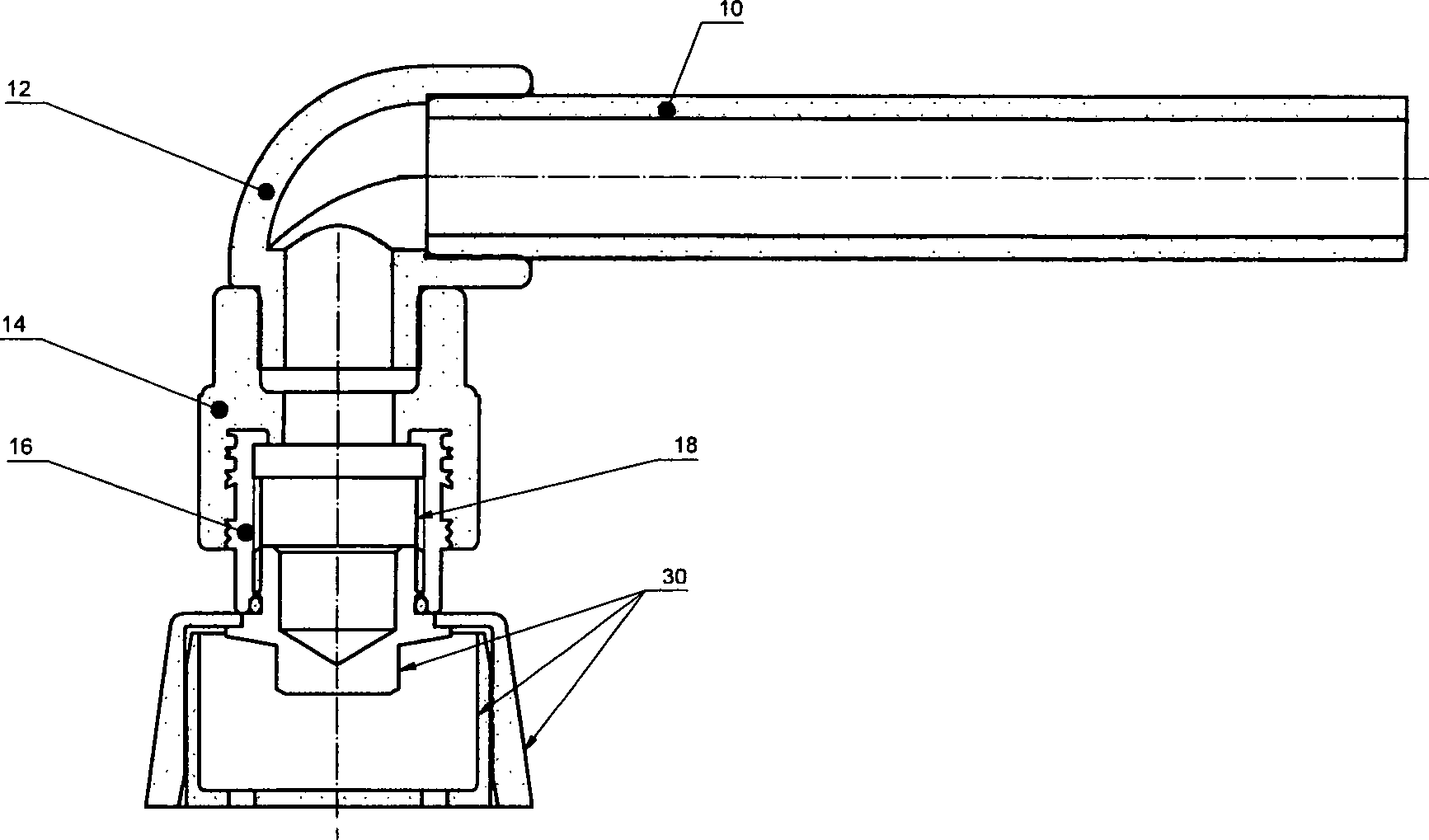
Erfindungsgemäß wird ein Montagebausatz zur Verfügung gestellt, der eine Dosenform mit innerer Kappe und diese umgebender Hülse aufweist, deren Querschnitt im Bereich der geschlossenen Stirnwandung der Kappe größer als im entfernt liegenden Bereich ist, wobei die Hülse in diesem Bereich einen nach innen gerichteten Randbereich aufweist, über den die Hülse mit den Anschlussstück verbindbar ist. Der nach innen gerichtete Randbereich ist dabei umlaufend und umgibt eine Öffnung, die von dem Schraubelement durchsetzt ist und innenseitig von einem Flansch des Schraubelementes abgedeckt ist. Somit ergibt sich eine geschlossene Einheit, in die Beton nicht eindringen kann.According to the invention a mounting kit provided, which has a can shape having inner cap and surrounding sleeve, whose cross section in the region of the closed end wall of Cap larger than in the remote area is, with the sleeve in this area one inside directed edge region over which the sleeve can be connected to the connection piece. The inward facing Edge area is circumferential and surrounds an opening, which is penetrated by the screw and inside of a Flange of the screw is covered. This results in a closed unit into which concrete can not penetrate.
Die Kappe weist in ihrer geschlossenen Stirnwandung zumindest eine Öffnung auf, die von einem mit der Verschalung verbindbaren Befestigungselement wie Schraube durchsetzbar ist.The Cap has at least one opening in its closed end wall on, by a connectable with the casing fastener how screw is enforceable.
Zur Montage wird zunächst die Kappe über zumindest eine Schraube auf die Verschalung der zu gießenden Betondecke geschraubt. Vorzugsweise sind sieben Öffnungen und somit sieben Schrauben vorgesehen, um die Kappe zu sichern. Sodann wird die Hülse über das Schraubelement mit dem Anschlussstück verschraubt und die so gebildete Einheit auf die Kappe gesteckt. Das Anschlussstück kann sodann unmittelbar mit einem Rohr wie Fallrohr oder über ein Winkelstück mit einem Rohr verbunden werden, über das bei im Betrieb befindlicher Sprinkleranlage Löschwasser zuführbar ist.to First, mount the cap over at least a screw on the shuttering of the concrete ceiling to be cast screwed. Preferably, there are seven openings and thus seven screws provided to secure the cap. Then the Sleeve over the screw with the fitting bolted and put the unit so formed on the cap. The fitting can then immediately with a pipe like downpipe or over an elbow with one Tube to be connected over that when in operation Sprinkleranlage extinguishing water can be supplied.
Nach dem Gießen des Betons und Abbinden dieses wird in bekannter Weise die Verschalung entfernt. Da die Hülse einerseits mit dem Anschlussstück und die Kappe andererseits mit der Verschalung verbunden ist, wird folglich beim Entfernen der Verschalung die Kappe mit abgezogen. Anschließend wird das Schraubelement gelöst, so dass sich die Hülse aus der Betondecke herausziehen lässt. Gleichzeitig ist das Gewinde des Anschluss stücks freigelegt, so dass unmittelbar oder gegebenenfalls über ein Ausgleichsfitting der Sprinkler montiert werden kann.To the casting of the concrete and setting this is in known Way the formwork removed. As the sleeve on the one hand with the fitting and the cap on the other hand with the Formwork is therefore connected when removing the formwork the cap pulled off. Subsequently, the screw is Loosened, so that the sleeve from the concrete ceiling pull out. At the same time the thread of the connection piece is exposed, so that directly or optionally via a compensating fitting the sprinkler can be mounted.
Weitere Einzelheiten, Vorteile und Merkmale der Erfindung ergeben sich nicht nur aus den Ansprüchen, den diesen zu entnehmenden Merkmalen – für sich und/oder in Kombination –, sondern auch aus der nachfolgenden Beschreibung eines der Zeichnung zu entnehmenden bevorzugten Ausführungsbeispiels.Further Details, advantages and features of the invention do not arise only from the claims, the features to be taken from them - for themselves and / or in combination - but also from the following Description of a drawing to be taken preferred embodiment.
Es zeigen:It demonstrate:
Um Sprinkler in verdeckter oder gegebenenfalls sichtbarer Anordnung in einer Betondecke anzuordnen, muss diese an den Stellen, in denen Sprinkler vorzusehen sind, entsprechende Aussparungen aufweisen, in denen einbetonierte Anschlussstücke enden, die mit Löschwasser führenden Rohren verbunden sind.Around Sprinklers in concealed or possibly visible arrangement To arrange in a concrete ceiling, this must be in the places where Provide sprinklers, have corresponding recesses, in which concreted connections end, which with extinguishing water leading pipes are connected.
In
Selbstverständlich
kann in das Anschlussstück
Um
in der Betondecke
Der
Montagebausatz
Des
Weiteren weist der Montagebausatz
Die
Außenform der Hülse
Die Öffnung
Wird
folglich das Schraubelement
Montagemäßig
wird nun wie folgt vorgegangen:
Zunächst wird die
Kappe
First, the cap
ZITATE ENTHALTEN IN DER BESCHREIBUNGQUOTES INCLUDE IN THE DESCRIPTION
Diese Liste der vom Anmelder aufgeführten Dokumente wurde automatisiert erzeugt und ist ausschließlich zur besseren Information des Lesers aufgenommen. Die Liste ist nicht Bestandteil der deutschen Patent- bzw. Gebrauchsmusteranmeldung. Das DPMA übernimmt keinerlei Haftung für etwaige Fehler oder Auslassungen.This list The documents listed by the applicant have been automated generated and is solely for better information recorded by the reader. The list is not part of the German Patent or utility model application. The DPMA takes over no liability for any errors or omissions.
Zitierte PatentliteraturCited patent literature
- - WO 2006/105758 A [0002] - WO 2006/105758 A [0002]
Claims (7)
Priority Applications (2)
| Application Number | Priority Date | Filing Date | Title |
|---|---|---|---|
| DE202009004938U DE202009004938U1 (en) | 2009-06-19 | 2009-06-19 | mounting kit |
| US12/711,290 US20100319196A1 (en) | 2009-06-19 | 2010-02-24 | Mounting kit and method for forming a recess in a concrete celling |
Applications Claiming Priority (1)
| Application Number | Priority Date | Filing Date | Title |
|---|---|---|---|
| DE202009004938U DE202009004938U1 (en) | 2009-06-19 | 2009-06-19 | mounting kit |
Publications (1)
| Publication Number | Publication Date |
|---|---|
| DE202009004938U1 true DE202009004938U1 (en) | 2009-10-01 |
Family
ID=41131302
Family Applications (1)
| Application Number | Title | Priority Date | Filing Date |
|---|---|---|---|
| DE202009004938U Expired - Lifetime DE202009004938U1 (en) | 2009-06-19 | 2009-06-19 | mounting kit |
Country Status (2)
| Country | Link |
|---|---|
| US (1) | US20100319196A1 (en) |
| DE (1) | DE202009004938U1 (en) |
Cited By (6)
| Publication number | Priority date | Publication date | Assignee | Title |
|---|---|---|---|---|
| DE102010012209A1 (en) * | 2010-03-19 | 2011-09-22 | Rehau Ag + Co. | Arrangement for manufacturing connection facility for connecting sprinkler at e.g. reinforced concrete ceiling, has shell designed as solid component and arranged in space between box and adaptor, where shell partly rests inside box |
| EP2586934A1 (en) | 2011-10-27 | 2013-05-01 | Georg Fischer JRG AG | Sprinkler connection box |
| WO2014052749A1 (en) * | 2012-09-28 | 2014-04-03 | Tyco Fire Products Lp | Concrete mold for sprinkler installation and installation method |
| AU2013202548B2 (en) * | 2012-09-28 | 2016-07-28 | Tyco Fire Products Lp | Concrete mold for sprinkler installation and installation method |
| DE102021128849A1 (en) | 2021-11-05 | 2023-05-11 | Henco Industries N.V. | Enclosure for installing an extinguishing device in a firefighting system, installation device and method for installing an extinguishing device in a firefighting system |
| WO2024165821A1 (en) * | 2023-02-09 | 2024-08-15 | A. Raymond Et Cie | Single-support attachment device for a formed structure |
Families Citing this family (3)
| Publication number | Priority date | Publication date | Assignee | Title |
|---|---|---|---|---|
| US10420972B2 (en) | 2017-06-12 | 2019-09-24 | Ramon Aguilar | Dummy head for sprinkler systems |
| US10937285B2 (en) | 2018-06-01 | 2021-03-02 | Johnson Controls Fire Protection LP | Systems and methods of alarm controls and directed audio evacuation |
| EP4007645A4 (en) * | 2019-08-02 | 2023-11-29 | Tyco Fire Products LP | SPRINKLER BOX FOR AN EMBEDDED SPRINKLER PIPE SYSTEM |
Citations (1)
| Publication number | Priority date | Publication date | Assignee | Title |
|---|---|---|---|---|
| WO2006105758A2 (en) | 2005-04-02 | 2006-10-12 | Minimax Gmbh & Co. Kg | Concealed sprinkler |
Family Cites Families (3)
| Publication number | Priority date | Publication date | Assignee | Title |
|---|---|---|---|---|
| US4164933A (en) * | 1976-10-06 | 1979-08-21 | Alosi Anthony C | Concrete solar collectors |
| AUPN633495A0 (en) * | 1995-11-03 | 1995-11-23 | Mcmahon, Michael John | Conduit positioning device for slabs |
| TWM310006U (en) * | 2006-09-13 | 2007-04-21 | Yuan Shin Entpr Co Ltd | Improved structure of hidden sprinkle nozzle set for fire control |
-
2009
- 2009-06-19 DE DE202009004938U patent/DE202009004938U1/en not_active Expired - Lifetime
-
2010
- 2010-02-24 US US12/711,290 patent/US20100319196A1/en not_active Abandoned
Patent Citations (1)
| Publication number | Priority date | Publication date | Assignee | Title |
|---|---|---|---|---|
| WO2006105758A2 (en) | 2005-04-02 | 2006-10-12 | Minimax Gmbh & Co. Kg | Concealed sprinkler |
Cited By (9)
| Publication number | Priority date | Publication date | Assignee | Title |
|---|---|---|---|---|
| DE102010012209A1 (en) * | 2010-03-19 | 2011-09-22 | Rehau Ag + Co. | Arrangement for manufacturing connection facility for connecting sprinkler at e.g. reinforced concrete ceiling, has shell designed as solid component and arranged in space between box and adaptor, where shell partly rests inside box |
| EP2586934A1 (en) | 2011-10-27 | 2013-05-01 | Georg Fischer JRG AG | Sprinkler connection box |
| EP2586934B1 (en) * | 2011-10-27 | 2017-12-06 | Georg Fischer JRG AG | Sprinkler connection box |
| WO2014052749A1 (en) * | 2012-09-28 | 2014-04-03 | Tyco Fire Products Lp | Concrete mold for sprinkler installation and installation method |
| US9303419B2 (en) | 2012-09-28 | 2016-04-05 | Tyco Fire Products Lp | Concrete mold for sprinkler installation and installation method |
| AU2013202548B2 (en) * | 2012-09-28 | 2016-07-28 | Tyco Fire Products Lp | Concrete mold for sprinkler installation and installation method |
| DE102021128849A1 (en) | 2021-11-05 | 2023-05-11 | Henco Industries N.V. | Enclosure for installing an extinguishing device in a firefighting system, installation device and method for installing an extinguishing device in a firefighting system |
| WO2024165821A1 (en) * | 2023-02-09 | 2024-08-15 | A. Raymond Et Cie | Single-support attachment device for a formed structure |
| FR3145764A1 (en) * | 2023-02-09 | 2024-08-16 | A. Raymond Et Cie | Single support fixing device for formwork structure |
Also Published As
| Publication number | Publication date |
|---|---|
| US20100319196A1 (en) | 2010-12-23 |
Similar Documents
| Publication | Publication Date | Title |
|---|---|---|
| DE202009004938U1 (en) | mounting kit | |
| EP3052710B1 (en) | Mounting plate for a lavatory body | |
| EP2998449A1 (en) | Bathroom drain fitting | |
| DE102012203394B4 (en) | Connection block for sanitary fittings | |
| DE2203370A1 (en) | DEVICE FOR ANCHORING PIPELINE OUTLETS IN THE WALL | |
| EP2586934B1 (en) | Sprinkler connection box | |
| DE2709446B2 (en) | Sanitary basin arrangement | |
| EP3117046B1 (en) | Intermediate holder | |
| EP2192252B1 (en) | Plug | |
| EP3523486B1 (en) | Arrangement for the installation and wall mounting of a wash basin | |
| DE102004008594B4 (en) | Sanitary outlet device | |
| DE102010012209A1 (en) | Arrangement for manufacturing connection facility for connecting sprinkler at e.g. reinforced concrete ceiling, has shell designed as solid component and arranged in space between box and adaptor, where shell partly rests inside box | |
| CH438166A (en) | Toilet cistern built into the wall | |
| EP2143847A2 (en) | Tap with built-in wall box | |
| DE102018133514A1 (en) | Toilet connection device for connecting a shower toilet on the wall and method for installing a shower toilet using a toilet connection device | |
| CH711488A1 (en) | <TITLE> Installation sleeve cover for closing an opening in an installation sleeve. | |
| DE102019101780A1 (en) | Water meter module and water meter module installation | |
| EP3061877B1 (en) | Sanitary fitting with a hose connection fixed with a clamp | |
| DE102022205026A1 (en) | Drain device for a pool | |
| DE102011013349A1 (en) | Discharge device e.g. floor drain for waste water used in e.g. bathroom, has sealing unit that is in contact with the drain port of trap | |
| AT13134U1 (en) | INSTALLATION PART | |
| EP2354335B1 (en) | Sanitary flush-mounted attachment with associated cladding element | |
| DE102006018734B3 (en) | Sanitary water pipe fitting with jet regulator | |
| DE102009053652A1 (en) | Roof penetration for piping through roof surface, comprises baseplate, passage pipe that is gripped by roof surface, ball, and outlet head | |
| DE2923506A1 (en) | Wash basin outflow valve assembly mounting - has wide holes through cover plate assisting aligned fixture attachments fitting |
Legal Events
| Date | Code | Title | Description |
|---|---|---|---|
| R163 | Identified publications notified | ||
| R207 | Utility model specification |
Effective date: 20091105 |
|
| R150 | Utility model maintained after payment of first maintenance fee after three years |
Effective date: 20120627 |
|
| R151 | Utility model maintained after payment of second maintenance fee after six years | ||
| R152 | Utility model maintained after payment of third maintenance fee after eight years | ||
| R071 | Expiry of right |