DE202009000070U1 - Ring spanner with swiveling head - Google Patents
Ring spanner with swiveling head Download PDFInfo
- Publication number
- DE202009000070U1 DE202009000070U1 DE200920000070 DE202009000070U DE202009000070U1 DE 202009000070 U1 DE202009000070 U1 DE 202009000070U1 DE 200920000070 DE200920000070 DE 200920000070 DE 202009000070 U DE202009000070 U DE 202009000070U DE 202009000070 U1 DE202009000070 U1 DE 202009000070U1
- Authority
- DE
- Germany
- Prior art keywords
- hole
- engagement pin
- teeth
- toothed
- ring
- Prior art date
- Legal status (The legal status is an assumption and is not a legal conclusion. Google has not performed a legal analysis and makes no representation as to the accuracy of the status listed.)
- Expired - Lifetime
Links
- 230000002093 peripheral effect Effects 0.000 claims abstract description 16
- 230000000630 rising effect Effects 0.000 claims description 5
- 238000006073 displacement reaction Methods 0.000 description 2
- 238000000034 method Methods 0.000 description 2
- BUHVIAUBTBOHAG-FOYDDCNASA-N (2r,3r,4s,5r)-2-[6-[[2-(3,5-dimethoxyphenyl)-2-(2-methylphenyl)ethyl]amino]purin-9-yl]-5-(hydroxymethyl)oxolane-3,4-diol Chemical compound COC1=CC(OC)=CC(C(CNC=2C=3N=CN(C=3N=CN=2)[C@H]2[C@@H]([C@H](O)[C@@H](CO)O2)O)C=2C(=CC=CC=2)C)=C1 BUHVIAUBTBOHAG-FOYDDCNASA-N 0.000 description 1
- 241000204888 Geobacter sp. Species 0.000 description 1
- 229910000831 Steel Inorganic materials 0.000 description 1
- 230000001419 dependent effect Effects 0.000 description 1
- 210000004247 hand Anatomy 0.000 description 1
- 238000012986 modification Methods 0.000 description 1
- 230000004048 modification Effects 0.000 description 1
- 239000010959 steel Substances 0.000 description 1
- 210000003813 thumb Anatomy 0.000 description 1
Classifications
-
- B—PERFORMING OPERATIONS; TRANSPORTING
- B25—HAND TOOLS; PORTABLE POWER-DRIVEN TOOLS; MANIPULATORS
- B25B—TOOLS OR BENCH DEVICES NOT OTHERWISE PROVIDED FOR, FOR FASTENING, CONNECTING, DISENGAGING OR HOLDING
- B25B13/00—Spanners; Wrenches
- B25B13/02—Spanners; Wrenches with rigid jaws
- B25B13/04—Spanners; Wrenches with rigid jaws of ring jaw type
-
- B—PERFORMING OPERATIONS; TRANSPORTING
- B25—HAND TOOLS; PORTABLE POWER-DRIVEN TOOLS; MANIPULATORS
- B25B—TOOLS OR BENCH DEVICES NOT OTHERWISE PROVIDED FOR, FOR FASTENING, CONNECTING, DISENGAGING OR HOLDING
- B25B13/00—Spanners; Wrenches
- B25B13/02—Spanners; Wrenches with rigid jaws
- B25B13/08—Spanners; Wrenches with rigid jaws of open jaw type
-
- B—PERFORMING OPERATIONS; TRANSPORTING
- B25—HAND TOOLS; PORTABLE POWER-DRIVEN TOOLS; MANIPULATORS
- B25G—HANDLES FOR HAND IMPLEMENTS
- B25G1/00—Handle constructions
- B25G1/06—Handle constructions reversible or adjustable for position
- B25G1/063—Handle constructions reversible or adjustable for position for screwdrivers, wrenches or spanners
Landscapes
- Engineering & Computer Science (AREA)
- Mechanical Engineering (AREA)
- Details Of Spanners, Wrenches, And Screw Drivers And Accessories (AREA)
Abstract
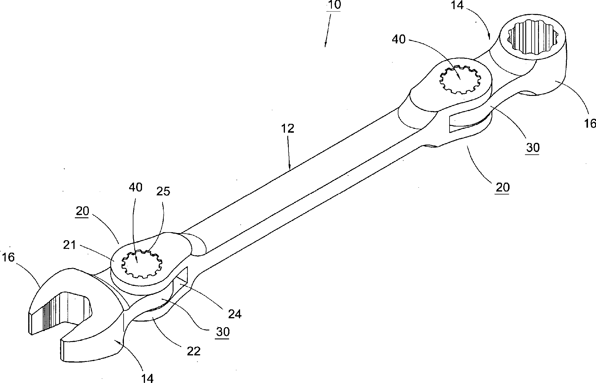
Ringschlüssel mit schwenkbarem Kopf, der einen Handgriff (12) und wenigstens einen Kopf (14) aufweist, die jeweils über ein erstes und ein zweites Ende (20, 30) miteinander gekoppelt sind, so dass ein Verstellen des relativen Winkels von ihnen durchführbar ist, wobei das andere Ende des Kopfs (14) als Schraubverbindungsteil (16) ausgebildet ist,
dadurch gekennzeichnet,
dass das erste Ende (20) eine obere Wand (21) und eine untere Wand (22) aufweist, die untereinander parallel zueinander angeordnet sind und einen Zwischenraum (24) bilden, wobei an der oberen Wand (21) ein erstes verzahntes Loch (25) ausgebildet ist, das an seinem Umfangsrand eine Mehrzahl von Zähnen (26) trägt, wobei an der unteren Wand (22) ein Durchgangsloch (27) ausgebildet ist, das dem ersten verzahnten Loch (25) entspricht;
dass am zweiten Ende (30) ein zweites verzahntes Loch (32) ausgebildet ist, an dessen Umfangswand eine Mehrzahl von Zähnen (34) vorgesehen ist, wobei sich das zweite Ende...A swivel head ring wrench comprising a handle (12) and at least one head (14) each coupled to each other via first and second ends (20, 30) such that adjustment of the relative angle thereof is feasible; the other end of the head (14) being designed as a screw connection part (16),
characterized,
in that the first end (20) has a top wall (21) and a bottom wall (22) mutually parallel to each other and forming a space (24), wherein on the top wall (21) a first toothed hole (25 formed on its peripheral edge a plurality of teeth (26), wherein on the lower wall (22) has a through hole (27) is formed, which corresponds to the first toothed hole (25);
in that a second toothed hole (32) is formed at the second end (30), on the circumferential wall of which a plurality of teeth (34) are provided, the second end being provided with a second toothed hole (32).
Description
Technisches GebietTechnical area
Die Erfindung betrifft ein Handwerkzeug, insbesondere einen Ringschlüssel mit schwenkbarem Kopf, der in verschiedenen Winkeln befestigbar ist.The The invention relates to a hand tool, in particular a ring spanner with swivel head, which can be fastened at different angles is.
Stand der TechnikState of the art
Bei
konventionellen Schlüsseln sind die Köpfe und
der Handgriff gewöhnlich miteinander fest verbunden. In
einem engen Raum oder an bestimmten Orten sitzt die Schraubenmutter
in einer nicht leicht erreichbaren Ecke, so dass ein konventioneller Schlüssel
nicht zum Einsatz kommen kann. Zur Lösung des o. g. Problems
hat der Erfinder ein Handwerkzeug mit Schnellschraubfunktion (
Beim
Schlüssel aus
Beim
Schlüssel aus
Bei den herkömmlichen Schlüsseln der o. g. Arten muss der Handgriff zum Verstellen des relativen Winkels des Kopfs zum Handgriff derart bewegt werden, dass sich der Handgriff und der Kopf relativ zueinander verschieben, um sich vom Eingriff zu lösen, wobei eine derartige Betätigung nur mit den beiden Händen ausführbar ist, nämlich dass die eine Hand den Handgriff festhält, während die andere Hand den Kopf befestigt, was für den Benutzer sehr aufwendig ist.at the conventional keys of o. g. Species must the handle for adjusting the relative angle of the head to Handle be moved so that the handle and the Move head relative to each other to disengage from the procedure such an operation only with both hands is executable, namely that one hand the Handle holds while the other hand holds the Head attached, which is very expensive for the user.
Aufgabe der ErfindungObject of the invention
Der Erfindung liegt die Aufgabe zugrunde, einen Ringschlüssel mit schwenkbarem Kopf zu schaffen, bei dem der Eingriff des Kopfs und des Handgriffs des Ringschlüssels leicht aufgehoben werden kann.Of the Invention is based on the object, a ring spanner to create with a swivel head, at which the engagement of the head and the handle of the ring wrench are easily reversed can be.
Technische LösungTechnical solution
Diese Aufgabe wird erfindungsgemäß durch einen Ringschlüssel mit schwenkbarem Kopf mit den Merkmalen des Anspruchs 1 gelöst. Vorteilhafte Ausgestaltungen sind Gegenstand der abhängigen Ansprüche.These The object is achieved by a ring spanner solved with pivoting head with the features of claim 1. Advantageous embodiments are the subject of the dependent Claims.
Kurze Beschreibung der ZeichnungShort description of the drawing
Wege der Ausführung der ErfindungWays of execution the invention
Im Folgenden werden Aufgaben, Merkmale und Vorteile der vorliegenden Erfindung anhand der detaillierten Beschreibung eines Ausführungsbeispiels und der beigefügten Zeichnungen näher erläutert. Jedoch soll die Erfindung nicht auf die Beschreibung und die beigefügten Zeichnungen beschränkt werden.in the Following are the tasks, features and benefits of the present Invention with reference to the detailed description of an embodiment and the accompanying drawings. However, the invention should not be limited to the description and attached Drawings are limited.
Das
erste Ende
Wie
aus
Am
zweiten Ende
Erfindungsgemäß ist
ferner ein Eingriffszapfen
Der
Eingriffszapfen
Für
die Verwendung der Erfindung wird auf
Wenn
der Eingriffszapfen
Beider
Verschiebung des Eingriffszapfens
Um
das erste und das zweite Ende von dem Eingriff aus
Die
Erfindung betrifft einen Ringschlüssel mit schwenkbarem
Kopf, wobei der Handgriff (
Die vorstehende Beschreibung stellt nur ein bevorzugtes Ausführungsbeispiels der Erfindung dar und soll nicht die Ansprüche beschränken. Alle gleichwertigen Änderungen und Modifikationen, die die in diesem technischen Bereich Sachkundigen gemäß der Beschreibung und den Zeichnungen der Erfindung vornehmen, gehören zum Schutzbereich der vorliegenden Erfindung. Der Schutzbereich der Erfindung richtet sich auf die nachstehenden Ansprüche.The The above description represents only a preferred embodiment The invention is not intended to limit the claims. All equivalent changes and modifications that the in this technical area expert according to the Description and the drawings of the invention include to the scope of the present invention. The protection area The invention is directed to the following claims.
- 1010
- Ringschlüsselkey ring
- 1212
- Handgriffhandle
- 1414
- Kopfhead
- 1616
- SchraubverbindungsteilSchraubverbindungsteil
- 2020
- erstes Endefirst The End
- 2121
- obere Wandupper wall
- 2222
- untere Wandlower wall
- 2424
- Zwischenraumgap
- 2525
- erstes verzahntes Lochfirst toothed hole
- 2626
- Zähneteeth
- 2727
- DurchgangslochThrough Hole
- 2828
- sich erhebender Anschlagringyourself uplifting stop ring
- 3030
- zweites Endesecond The End
- 3232
- zweites verzahntes Lochsecond toothed hole
- 3434
- Zähneteeth
- 3636
- Lochhole
- 4040
- Eingriffszapfenengagement pin
- 4242
- Zähneteeth
- 4444
- Stützrandsupporting edge
- 4545
- Ringnutring groove
- 4646
- elastisches Positionierelementelastic positioning
ZITATE ENTHALTEN IN DER BESCHREIBUNGQUOTES INCLUDE IN THE DESCRIPTION
Diese Liste der vom Anmelder aufgeführten Dokumente wurde automatisiert erzeugt und ist ausschließlich zur besseren Information des Lesers aufgenommen. Die Liste ist nicht Bestandteil der deutschen Patent- bzw. Gebrauchsmusteranmeldung. Das DPMA übernimmt keinerlei Haftung für etwaige Fehler oder Auslassungen.This list The documents listed by the applicant have been automated generated and is solely for better information recorded by the reader. The list is not part of the German Patent or utility model application. The DPMA takes over no liability for any errors or omissions.
Zitierte PatentliteraturCited patent literature
- - US 6928904 [0002, 0003, 0017] - US 6928904 [0002, 0003, 0017]
- - US 7373861 [0002, 0004] - US 7373861 [0002, 0004]
Claims (9)
Priority Applications (1)
| Application Number | Priority Date | Filing Date | Title |
|---|---|---|---|
| DE200920000070 DE202009000070U1 (en) | 2009-01-29 | 2009-01-29 | Ring spanner with swiveling head |
Applications Claiming Priority (1)
| Application Number | Priority Date | Filing Date | Title |
|---|---|---|---|
| DE200920000070 DE202009000070U1 (en) | 2009-01-29 | 2009-01-29 | Ring spanner with swiveling head |
Publications (1)
| Publication Number | Publication Date |
|---|---|
| DE202009000070U1 true DE202009000070U1 (en) | 2009-06-18 |
Family
ID=40786218
Family Applications (1)
| Application Number | Title | Priority Date | Filing Date |
|---|---|---|---|
| DE200920000070 Expired - Lifetime DE202009000070U1 (en) | 2009-01-29 | 2009-01-29 | Ring spanner with swiveling head |
Country Status (1)
| Country | Link |
|---|---|
| DE (1) | DE202009000070U1 (en) |
Cited By (5)
| Publication number | Priority date | Publication date | Assignee | Title |
|---|---|---|---|---|
| WO2011089297A1 (en) * | 2010-01-19 | 2011-07-28 | Sergio Oliver Lagardera | Hand tool |
| DE202012100670U1 (en) | 2011-07-21 | 2012-04-03 | Kabo Tool Company | Hand tool with swivel angle adjustment |
| DE102018005133A1 (en) * | 2018-06-28 | 2020-01-02 | Peter Malkomes | ratchet wrench |
| CN112692768A (en) * | 2020-12-21 | 2021-04-23 | 海南电网有限责任公司五指山供电局 | Multifunctional telescopic wrench |
| CN116619283A (en) * | 2022-02-18 | 2023-08-22 | 英发企业股份有限公司 | multi-angle wrench |
Citations (2)
| Publication number | Priority date | Publication date | Assignee | Title |
|---|---|---|---|---|
| US6928904B2 (en) | 2003-08-29 | 2005-08-16 | Chih-Ching Hsien | Hand tool having a quick driving effect |
| US7373861B2 (en) | 2006-01-17 | 2008-05-20 | Chih-Ching Hsieh | Pivoting assembly of a hand tool |
-
2009
- 2009-01-29 DE DE200920000070 patent/DE202009000070U1/en not_active Expired - Lifetime
Patent Citations (2)
| Publication number | Priority date | Publication date | Assignee | Title |
|---|---|---|---|---|
| US6928904B2 (en) | 2003-08-29 | 2005-08-16 | Chih-Ching Hsien | Hand tool having a quick driving effect |
| US7373861B2 (en) | 2006-01-17 | 2008-05-20 | Chih-Ching Hsieh | Pivoting assembly of a hand tool |
Cited By (6)
| Publication number | Priority date | Publication date | Assignee | Title |
|---|---|---|---|---|
| WO2011089297A1 (en) * | 2010-01-19 | 2011-07-28 | Sergio Oliver Lagardera | Hand tool |
| ES2377093A1 (en) * | 2010-01-19 | 2012-03-22 | Sergio Oliver Lagardera | Hand tool |
| DE202012100670U1 (en) | 2011-07-21 | 2012-04-03 | Kabo Tool Company | Hand tool with swivel angle adjustment |
| DE102018005133A1 (en) * | 2018-06-28 | 2020-01-02 | Peter Malkomes | ratchet wrench |
| CN112692768A (en) * | 2020-12-21 | 2021-04-23 | 海南电网有限责任公司五指山供电局 | Multifunctional telescopic wrench |
| CN116619283A (en) * | 2022-02-18 | 2023-08-22 | 英发企业股份有限公司 | multi-angle wrench |
Similar Documents
| Publication | Publication Date | Title |
|---|---|---|
| DE102015117621B3 (en) | Arrangement for connecting a wrench with a receiving device | |
| DE202010000010U1 (en) | Adjustable lever | |
| DE1777007A1 (en) | Device for fastening workpieces for the purpose of machining | |
| DE102011054986A1 (en) | tongs | |
| DE202007004324U1 (en) | Adapter coupling device | |
| DE202009000070U1 (en) | Ring spanner with swiveling head | |
| DE102016102058B4 (en) | Torque wrench with the possibility to accommodate drive heads | |
| DE202020102347U1 (en) | A device that enables immediate and precise locking and loosening of a rope | |
| DE20205092U1 (en) | Adjustable wrench | |
| WO2009074190A1 (en) | Adapter for coupling a rod, such as a locking rod of a rod-type closure, to a lever, such as an actuating lever of the rod-type closure | |
| DE20108604U1 (en) | Tool wrench with a nut holder | |
| DE20006912U1 (en) | Scaffold holder for an eaves scaffold | |
| EP3668669A1 (en) | Portable milling machine having a spanner | |
| DE19819457A1 (en) | Hand-held tool with turning tool head to which socket spanner can be attached | |
| DE102012102681A1 (en) | Tool unit for use with quick-release mechanism for adjustable front plates, comprises lever with handle and both ends formed as rotatable end portions, where pin is rotated by rotating lever for adjusting distance between two front plates | |
| DE202017103114U1 (en) | transmission tools | |
| DE202008007740U1 (en) | Universal pry bar | |
| DE2650506A1 (en) | Open sided socket for use with ratchet wrench - has bell-section with sprung ball detent forced over nut flat to retain socket | |
| DE202019105147U1 (en) | Quick release Ratchet T wrench | |
| EP4353665B1 (en) | Stop point | |
| DE2912985A1 (en) | STAMP | |
| DE9204329U1 (en) | Processing unit | |
| DE102014105768B3 (en) | Pliers for a C-shaped ring | |
| DE202012104193U1 (en) | Hand tool with an adjustment mechanism | |
| DE102010015592A1 (en) | Device for use with tool for holding working elements, particularly holding against tightening or releasing of screw head or screw nut, has retaining part for retaining of working elements, where counter holder is assigned to tool |
Legal Events
| Date | Code | Title | Description |
|---|---|---|---|
| R207 | Utility model specification |
Effective date: 20090723 |
|
| R150 | Term of protection extended to 6 years | ||
| R150 | Term of protection extended to 6 years |
Effective date: 20111209 |
|
| R082 | Change of representative |
Representative=s name: LANGPATENT ANWALTSKANZLEI IP LAW FIRM, DE |
|
| R151 | Term of protection extended to 8 years | ||
| R151 | Term of protection extended to 8 years |
Effective date: 20141211 |
|
| R152 | Term of protection extended to 10 years | ||
| R071 | Expiry of right |