DE102022105041A1 - Coating technology for plastic containers - Google Patents
Coating technology for plastic containers Download PDFInfo
- Publication number
- DE102022105041A1 DE102022105041A1 DE102022105041.6A DE102022105041A DE102022105041A1 DE 102022105041 A1 DE102022105041 A1 DE 102022105041A1 DE 102022105041 A DE102022105041 A DE 102022105041A DE 102022105041 A1 DE102022105041 A1 DE 102022105041A1
- Authority
- DE
- Germany
- Prior art keywords
- zone
- coating
- barrier
- layer
- nanometers
- Prior art date
- Legal status (The legal status is an assumption and is not a legal conclusion. Google has not performed a legal analysis and makes no representation as to the accuracy of the status listed.)
- Pending
Links
Images


Classifications
-
- C—CHEMISTRY; METALLURGY
- C08—ORGANIC MACROMOLECULAR COMPOUNDS; THEIR PREPARATION OR CHEMICAL WORKING-UP; COMPOSITIONS BASED THEREON
- C08J—WORKING-UP; GENERAL PROCESSES OF COMPOUNDING; AFTER-TREATMENT NOT COVERED BY SUBCLASSES C08B, C08C, C08F, C08G or C08H
- C08J7/00—Chemical treatment or coating of shaped articles made of macromolecular substances
- C08J7/04—Coating
- C08J7/048—Forming gas barrier coatings
-
- B—PERFORMING OPERATIONS; TRANSPORTING
- B05—SPRAYING OR ATOMISING IN GENERAL; APPLYING FLUENT MATERIALS TO SURFACES, IN GENERAL
- B05D—PROCESSES FOR APPLYING FLUENT MATERIALS TO SURFACES, IN GENERAL
- B05D1/00—Processes for applying liquids or other fluent materials
- B05D1/60—Deposition of organic layers from vapour phase
-
- B—PERFORMING OPERATIONS; TRANSPORTING
- B05—SPRAYING OR ATOMISING IN GENERAL; APPLYING FLUENT MATERIALS TO SURFACES, IN GENERAL
- B05D—PROCESSES FOR APPLYING FLUENT MATERIALS TO SURFACES, IN GENERAL
- B05D1/00—Processes for applying liquids or other fluent materials
- B05D1/62—Plasma-deposition of organic layers
-
- B—PERFORMING OPERATIONS; TRANSPORTING
- B05—SPRAYING OR ATOMISING IN GENERAL; APPLYING FLUENT MATERIALS TO SURFACES, IN GENERAL
- B05D—PROCESSES FOR APPLYING FLUENT MATERIALS TO SURFACES, IN GENERAL
- B05D3/00—Pretreatment of surfaces to which liquids or other fluent materials are to be applied; After-treatment of applied coatings, e.g. intermediate treating of an applied coating preparatory to subsequent applications of liquids or other fluent materials
- B05D3/04—Pretreatment of surfaces to which liquids or other fluent materials are to be applied; After-treatment of applied coatings, e.g. intermediate treating of an applied coating preparatory to subsequent applications of liquids or other fluent materials by exposure to gases
- B05D3/0486—Operating the coating or treatment in a controlled atmosphere
-
- B—PERFORMING OPERATIONS; TRANSPORTING
- B05—SPRAYING OR ATOMISING IN GENERAL; APPLYING FLUENT MATERIALS TO SURFACES, IN GENERAL
- B05D—PROCESSES FOR APPLYING FLUENT MATERIALS TO SURFACES, IN GENERAL
- B05D7/00—Processes, other than flocking, specially adapted for applying liquids or other fluent materials to particular surfaces or for applying particular liquids or other fluent materials
- B05D7/02—Processes, other than flocking, specially adapted for applying liquids or other fluent materials to particular surfaces or for applying particular liquids or other fluent materials to macromolecular substances, e.g. rubber
-
- B—PERFORMING OPERATIONS; TRANSPORTING
- B05—SPRAYING OR ATOMISING IN GENERAL; APPLYING FLUENT MATERIALS TO SURFACES, IN GENERAL
- B05D—PROCESSES FOR APPLYING FLUENT MATERIALS TO SURFACES, IN GENERAL
- B05D7/00—Processes, other than flocking, specially adapted for applying liquids or other fluent materials to particular surfaces or for applying particular liquids or other fluent materials
- B05D7/22—Processes, other than flocking, specially adapted for applying liquids or other fluent materials to particular surfaces or for applying particular liquids or other fluent materials to internal surfaces, e.g. of tubes
- B05D7/227—Processes, other than flocking, specially adapted for applying liquids or other fluent materials to particular surfaces or for applying particular liquids or other fluent materials to internal surfaces, e.g. of tubes of containers, cans or the like
-
- C—CHEMISTRY; METALLURGY
- C08—ORGANIC MACROMOLECULAR COMPOUNDS; THEIR PREPARATION OR CHEMICAL WORKING-UP; COMPOSITIONS BASED THEREON
- C08J—WORKING-UP; GENERAL PROCESSES OF COMPOUNDING; AFTER-TREATMENT NOT COVERED BY SUBCLASSES C08B, C08C, C08F, C08G or C08H
- C08J7/00—Chemical treatment or coating of shaped articles made of macromolecular substances
- C08J7/04—Coating
- C08J7/0427—Coating with only one layer of a composition containing a polymer binder
-
- C—CHEMISTRY; METALLURGY
- C08—ORGANIC MACROMOLECULAR COMPOUNDS; THEIR PREPARATION OR CHEMICAL WORKING-UP; COMPOSITIONS BASED THEREON
- C08J—WORKING-UP; GENERAL PROCESSES OF COMPOUNDING; AFTER-TREATMENT NOT COVERED BY SUBCLASSES C08B, C08C, C08F, C08G or C08H
- C08J7/00—Chemical treatment or coating of shaped articles made of macromolecular substances
- C08J7/04—Coating
- C08J7/043—Improving the adhesiveness of the coatings per se, e.g. forming primers
-
- C—CHEMISTRY; METALLURGY
- C23—COATING METALLIC MATERIAL; COATING MATERIAL WITH METALLIC MATERIAL; CHEMICAL SURFACE TREATMENT; DIFFUSION TREATMENT OF METALLIC MATERIAL; COATING BY VACUUM EVAPORATION, BY SPUTTERING, BY ION IMPLANTATION OR BY CHEMICAL VAPOUR DEPOSITION, IN GENERAL; INHIBITING CORROSION OF METALLIC MATERIAL OR INCRUSTATION IN GENERAL
- C23C—COATING METALLIC MATERIAL; COATING MATERIAL WITH METALLIC MATERIAL; SURFACE TREATMENT OF METALLIC MATERIAL BY DIFFUSION INTO THE SURFACE, BY CHEMICAL CONVERSION OR SUBSTITUTION; COATING BY VACUUM EVAPORATION, BY SPUTTERING, BY ION IMPLANTATION OR BY CHEMICAL VAPOUR DEPOSITION, IN GENERAL
- C23C16/00—Chemical coating by decomposition of gaseous compounds, without leaving reaction products of surface material in the coating, i.e. chemical vapour deposition [CVD] processes
- C23C16/02—Pretreatment of the material to be coated
- C23C16/0272—Deposition of sub-layers, e.g. to promote the adhesion of the main coating
- C23C16/029—Graded interfaces
-
- C—CHEMISTRY; METALLURGY
- C23—COATING METALLIC MATERIAL; COATING MATERIAL WITH METALLIC MATERIAL; CHEMICAL SURFACE TREATMENT; DIFFUSION TREATMENT OF METALLIC MATERIAL; COATING BY VACUUM EVAPORATION, BY SPUTTERING, BY ION IMPLANTATION OR BY CHEMICAL VAPOUR DEPOSITION, IN GENERAL; INHIBITING CORROSION OF METALLIC MATERIAL OR INCRUSTATION IN GENERAL
- C23C—COATING METALLIC MATERIAL; COATING MATERIAL WITH METALLIC MATERIAL; SURFACE TREATMENT OF METALLIC MATERIAL BY DIFFUSION INTO THE SURFACE, BY CHEMICAL CONVERSION OR SUBSTITUTION; COATING BY VACUUM EVAPORATION, BY SPUTTERING, BY ION IMPLANTATION OR BY CHEMICAL VAPOUR DEPOSITION, IN GENERAL
- C23C16/00—Chemical coating by decomposition of gaseous compounds, without leaving reaction products of surface material in the coating, i.e. chemical vapour deposition [CVD] processes
- C23C16/04—Coating on selected surface areas, e.g. using masks
- C23C16/045—Coating cavities or hollow spaces, e.g. interior of tubes; Infiltration of porous substrates
-
- C—CHEMISTRY; METALLURGY
- C23—COATING METALLIC MATERIAL; COATING MATERIAL WITH METALLIC MATERIAL; CHEMICAL SURFACE TREATMENT; DIFFUSION TREATMENT OF METALLIC MATERIAL; COATING BY VACUUM EVAPORATION, BY SPUTTERING, BY ION IMPLANTATION OR BY CHEMICAL VAPOUR DEPOSITION, IN GENERAL; INHIBITING CORROSION OF METALLIC MATERIAL OR INCRUSTATION IN GENERAL
- C23C—COATING METALLIC MATERIAL; COATING MATERIAL WITH METALLIC MATERIAL; SURFACE TREATMENT OF METALLIC MATERIAL BY DIFFUSION INTO THE SURFACE, BY CHEMICAL CONVERSION OR SUBSTITUTION; COATING BY VACUUM EVAPORATION, BY SPUTTERING, BY ION IMPLANTATION OR BY CHEMICAL VAPOUR DEPOSITION, IN GENERAL
- C23C16/00—Chemical coating by decomposition of gaseous compounds, without leaving reaction products of surface material in the coating, i.e. chemical vapour deposition [CVD] processes
- C23C16/22—Chemical coating by decomposition of gaseous compounds, without leaving reaction products of surface material in the coating, i.e. chemical vapour deposition [CVD] processes characterised by the deposition of inorganic material, other than metallic material
- C23C16/30—Deposition of compounds, mixtures or solid solutions, e.g. borides, carbides, nitrides
- C23C16/40—Oxides
- C23C16/401—Oxides containing silicon
-
- C—CHEMISTRY; METALLURGY
- C23—COATING METALLIC MATERIAL; COATING MATERIAL WITH METALLIC MATERIAL; CHEMICAL SURFACE TREATMENT; DIFFUSION TREATMENT OF METALLIC MATERIAL; COATING BY VACUUM EVAPORATION, BY SPUTTERING, BY ION IMPLANTATION OR BY CHEMICAL VAPOUR DEPOSITION, IN GENERAL; INHIBITING CORROSION OF METALLIC MATERIAL OR INCRUSTATION IN GENERAL
- C23C—COATING METALLIC MATERIAL; COATING MATERIAL WITH METALLIC MATERIAL; SURFACE TREATMENT OF METALLIC MATERIAL BY DIFFUSION INTO THE SURFACE, BY CHEMICAL CONVERSION OR SUBSTITUTION; COATING BY VACUUM EVAPORATION, BY SPUTTERING, BY ION IMPLANTATION OR BY CHEMICAL VAPOUR DEPOSITION, IN GENERAL
- C23C16/00—Chemical coating by decomposition of gaseous compounds, without leaving reaction products of surface material in the coating, i.e. chemical vapour deposition [CVD] processes
- C23C16/44—Chemical coating by decomposition of gaseous compounds, without leaving reaction products of surface material in the coating, i.e. chemical vapour deposition [CVD] processes characterised by the method of coating
- C23C16/50—Chemical coating by decomposition of gaseous compounds, without leaving reaction products of surface material in the coating, i.e. chemical vapour deposition [CVD] processes characterised by the method of coating using electric discharges
- C23C16/511—Chemical coating by decomposition of gaseous compounds, without leaving reaction products of surface material in the coating, i.e. chemical vapour deposition [CVD] processes characterised by the method of coating using electric discharges using microwave discharges
-
- C—CHEMISTRY; METALLURGY
- C23—COATING METALLIC MATERIAL; COATING MATERIAL WITH METALLIC MATERIAL; CHEMICAL SURFACE TREATMENT; DIFFUSION TREATMENT OF METALLIC MATERIAL; COATING BY VACUUM EVAPORATION, BY SPUTTERING, BY ION IMPLANTATION OR BY CHEMICAL VAPOUR DEPOSITION, IN GENERAL; INHIBITING CORROSION OF METALLIC MATERIAL OR INCRUSTATION IN GENERAL
- C23C—COATING METALLIC MATERIAL; COATING MATERIAL WITH METALLIC MATERIAL; SURFACE TREATMENT OF METALLIC MATERIAL BY DIFFUSION INTO THE SURFACE, BY CHEMICAL CONVERSION OR SUBSTITUTION; COATING BY VACUUM EVAPORATION, BY SPUTTERING, BY ION IMPLANTATION OR BY CHEMICAL VAPOUR DEPOSITION, IN GENERAL
- C23C16/00—Chemical coating by decomposition of gaseous compounds, without leaving reaction products of surface material in the coating, i.e. chemical vapour deposition [CVD] processes
- C23C16/44—Chemical coating by decomposition of gaseous compounds, without leaving reaction products of surface material in the coating, i.e. chemical vapour deposition [CVD] processes characterised by the method of coating
- C23C16/50—Chemical coating by decomposition of gaseous compounds, without leaving reaction products of surface material in the coating, i.e. chemical vapour deposition [CVD] processes characterised by the method of coating using electric discharges
- C23C16/515—Chemical coating by decomposition of gaseous compounds, without leaving reaction products of surface material in the coating, i.e. chemical vapour deposition [CVD] processes characterised by the method of coating using electric discharges using pulsed discharges
-
- B—PERFORMING OPERATIONS; TRANSPORTING
- B05—SPRAYING OR ATOMISING IN GENERAL; APPLYING FLUENT MATERIALS TO SURFACES, IN GENERAL
- B05D—PROCESSES FOR APPLYING FLUENT MATERIALS TO SURFACES, IN GENERAL
- B05D2201/00—Polymeric substrate or laminate
- B05D2201/02—Polymeric substrate
-
- B—PERFORMING OPERATIONS; TRANSPORTING
- B05—SPRAYING OR ATOMISING IN GENERAL; APPLYING FLUENT MATERIALS TO SURFACES, IN GENERAL
- B05D—PROCESSES FOR APPLYING FLUENT MATERIALS TO SURFACES, IN GENERAL
- B05D2259/00—Applying the material to the internal surface of hollow articles other than tubes
-
- B—PERFORMING OPERATIONS; TRANSPORTING
- B05—SPRAYING OR ATOMISING IN GENERAL; APPLYING FLUENT MATERIALS TO SURFACES, IN GENERAL
- B05D—PROCESSES FOR APPLYING FLUENT MATERIALS TO SURFACES, IN GENERAL
- B05D2350/00—Pretreatment of the substrate
- B05D2350/60—Adding a layer before coating
-
- B—PERFORMING OPERATIONS; TRANSPORTING
- B05—SPRAYING OR ATOMISING IN GENERAL; APPLYING FLUENT MATERIALS TO SURFACES, IN GENERAL
- B05D—PROCESSES FOR APPLYING FLUENT MATERIALS TO SURFACES, IN GENERAL
- B05D2401/00—Form of the coating product, e.g. solution, water dispersion, powders or the like
- B05D2401/30—Form of the coating product, e.g. solution, water dispersion, powders or the like the coating being applied in other forms than involving eliminable solvent, diluent or dispersant
- B05D2401/33—Form of the coating product, e.g. solution, water dispersion, powders or the like the coating being applied in other forms than involving eliminable solvent, diluent or dispersant applied as vapours polymerising in situ
-
- B—PERFORMING OPERATIONS; TRANSPORTING
- B05—SPRAYING OR ATOMISING IN GENERAL; APPLYING FLUENT MATERIALS TO SURFACES, IN GENERAL
- B05D—PROCESSES FOR APPLYING FLUENT MATERIALS TO SURFACES, IN GENERAL
- B05D2490/00—Intermixed layers
- B05D2490/50—Intermixed layers compositions varying with a gradient perpendicular to the surface
-
- B—PERFORMING OPERATIONS; TRANSPORTING
- B05—SPRAYING OR ATOMISING IN GENERAL; APPLYING FLUENT MATERIALS TO SURFACES, IN GENERAL
- B05D—PROCESSES FOR APPLYING FLUENT MATERIALS TO SURFACES, IN GENERAL
- B05D2518/00—Other type of polymers
- B05D2518/10—Silicon-containing polymers
-
- B—PERFORMING OPERATIONS; TRANSPORTING
- B05—SPRAYING OR ATOMISING IN GENERAL; APPLYING FLUENT MATERIALS TO SURFACES, IN GENERAL
- B05D—PROCESSES FOR APPLYING FLUENT MATERIALS TO SURFACES, IN GENERAL
- B05D2518/00—Other type of polymers
- B05D2518/10—Silicon-containing polymers
- B05D2518/12—Ceramic precursors (polysiloxanes, polysilazanes)
-
- B—PERFORMING OPERATIONS; TRANSPORTING
- B05—SPRAYING OR ATOMISING IN GENERAL; APPLYING FLUENT MATERIALS TO SURFACES, IN GENERAL
- B05D—PROCESSES FOR APPLYING FLUENT MATERIALS TO SURFACES, IN GENERAL
- B05D3/00—Pretreatment of surfaces to which liquids or other fluent materials are to be applied; After-treatment of applied coatings, e.g. intermediate treating of an applied coating preparatory to subsequent applications of liquids or other fluent materials
- B05D3/02—Pretreatment of surfaces to which liquids or other fluent materials are to be applied; After-treatment of applied coatings, e.g. intermediate treating of an applied coating preparatory to subsequent applications of liquids or other fluent materials by baking
- B05D3/0254—After-treatment
- B05D3/029—After-treatment with microwaves
-
- B—PERFORMING OPERATIONS; TRANSPORTING
- B05—SPRAYING OR ATOMISING IN GENERAL; APPLYING FLUENT MATERIALS TO SURFACES, IN GENERAL
- B05D—PROCESSES FOR APPLYING FLUENT MATERIALS TO SURFACES, IN GENERAL
- B05D3/00—Pretreatment of surfaces to which liquids or other fluent materials are to be applied; After-treatment of applied coatings, e.g. intermediate treating of an applied coating preparatory to subsequent applications of liquids or other fluent materials
- B05D3/04—Pretreatment of surfaces to which liquids or other fluent materials are to be applied; After-treatment of applied coatings, e.g. intermediate treating of an applied coating preparatory to subsequent applications of liquids or other fluent materials by exposure to gases
- B05D3/0406—Pretreatment of surfaces to which liquids or other fluent materials are to be applied; After-treatment of applied coatings, e.g. intermediate treating of an applied coating preparatory to subsequent applications of liquids or other fluent materials by exposure to gases the gas being air
-
- B—PERFORMING OPERATIONS; TRANSPORTING
- B05—SPRAYING OR ATOMISING IN GENERAL; APPLYING FLUENT MATERIALS TO SURFACES, IN GENERAL
- B05D—PROCESSES FOR APPLYING FLUENT MATERIALS TO SURFACES, IN GENERAL
- B05D3/00—Pretreatment of surfaces to which liquids or other fluent materials are to be applied; After-treatment of applied coatings, e.g. intermediate treating of an applied coating preparatory to subsequent applications of liquids or other fluent materials
- B05D3/06—Pretreatment of surfaces to which liquids or other fluent materials are to be applied; After-treatment of applied coatings, e.g. intermediate treating of an applied coating preparatory to subsequent applications of liquids or other fluent materials by exposure to radiation
-
- C—CHEMISTRY; METALLURGY
- C08—ORGANIC MACROMOLECULAR COMPOUNDS; THEIR PREPARATION OR CHEMICAL WORKING-UP; COMPOSITIONS BASED THEREON
- C08J—WORKING-UP; GENERAL PROCESSES OF COMPOUNDING; AFTER-TREATMENT NOT COVERED BY SUBCLASSES C08B, C08C, C08F, C08G or C08H
- C08J2323/00—Characterised by the use of homopolymers or copolymers of unsaturated aliphatic hydrocarbons having only one carbon-to-carbon double bond; Derivatives of such polymers
- C08J2323/02—Characterised by the use of homopolymers or copolymers of unsaturated aliphatic hydrocarbons having only one carbon-to-carbon double bond; Derivatives of such polymers not modified by chemical after treatment
-
- C—CHEMISTRY; METALLURGY
- C08—ORGANIC MACROMOLECULAR COMPOUNDS; THEIR PREPARATION OR CHEMICAL WORKING-UP; COMPOSITIONS BASED THEREON
- C08J—WORKING-UP; GENERAL PROCESSES OF COMPOUNDING; AFTER-TREATMENT NOT COVERED BY SUBCLASSES C08B, C08C, C08F, C08G or C08H
- C08J2467/00—Characterised by the use of polyesters obtained by reactions forming a carboxylic ester link in the main chain; Derivatives of such polymers
- C08J2467/02—Polyesters derived from dicarboxylic acids and dihydroxy compounds
Landscapes
- Chemical & Material Sciences (AREA)
- Engineering & Computer Science (AREA)
- Organic Chemistry (AREA)
- Chemical Kinetics & Catalysis (AREA)
- General Chemical & Material Sciences (AREA)
- Materials Engineering (AREA)
- Mechanical Engineering (AREA)
- Metallurgy (AREA)
- Plasma & Fusion (AREA)
- Physics & Mathematics (AREA)
- Polymers & Plastics (AREA)
- Health & Medical Sciences (AREA)
- Medicinal Chemistry (AREA)
- Inorganic Chemistry (AREA)
- Life Sciences & Earth Sciences (AREA)
- Wood Science & Technology (AREA)
- Chemical Vapour Deposition (AREA)
- Coating Of Shaped Articles Made Of Macromolecular Substances (AREA)
- Laminated Bodies (AREA)
- Details Of Rigid Or Semi-Rigid Containers (AREA)
- Application Of Or Painting With Fluid Materials (AREA)
Abstract
Die Erfindung liegt auf dem Gebiet der Kunststoffbeschichtung mittels plasmaunterstützter chemischer Gasphasenabscheidung (PECVD). Mit der Erfindung lassen sich insbesondere recyclebare Kunststoffbehälter zur Lagerung aggressiver Chemikalien mit einer stabilen Migrationsbarriere beschichten. Es werden ein Verfahren und eine Beschichtung offenbart. Mit dem Verfahren lässt sich eine Beschichtung aus einem Prozessgasgemisch aus mindestens einem Präkursor und einem Reaktivgas, das zu einem Plasma angeregt wird, abscheiden. Durch Einstellung des Reaktivgasanteils im Prozessgasgemisch und Variation der massebezogenen Anregungsenergie lässt sich eine Gradientenschicht zur Herstellung einer chemisch beständigen Migrationssperre auf dem Kunststoffsubstrat abscheiden.The invention is in the field of plastic coating using plasma enhanced chemical vapor deposition (PECVD). With the invention, in particular, recyclable plastic containers for storing aggressive chemicals can be coated with a stable migration barrier. A method and a coating are disclosed. With the method, a coating can be deposited from a process gas mixture of at least one precursor and a reactive gas that is excited to form a plasma. By adjusting the proportion of reactive gas in the process gas mixture and varying the mass-related excitation energy, a gradient layer can be deposited on the plastic substrate to produce a chemically resistant migration barrier.
Description
Die Erfindung liegt auf dem Gebiet der Kunststoffbeschichtung mittels plasmaunterstützter chemischer Gasphasenabscheidung (engl.: Plasma Enhanced Chemical Vapour Deposition, PECVD).The invention lies in the field of plastic coating using plasma-enhanced chemical vapor deposition (PECVD).
In der Industrie werden Kunststoffbehälter, z.B. Flaschen oder Kanister, zur Lagerung verschiedenster Flüssigkeiten eingesetzt. Die Eigenschaften des Kunststoffs wirken sich auf die Eignung des Materials zur Lagerung des jeweiligen Mediums sowie auf die Herstellungskosten des Behälters aus.In industry, plastic containers, e.g. bottles or canisters, are used to store a wide variety of liquids. The properties of the plastic affect the material's suitability for storing the medium in question, as well as the cost of manufacturing the container.
Die Eignung des Materials hängt insbesondere von den Permeationseigenschaften des Kunststoffs gegenüber verschiedenen Gasen (z.B. Sauerstoff aus der Umgebungsluft), Lösemitteln, Aromaten, Farbstoffen oder sonstigen Stoffen sowie der Beständigkeit des Kunststoffs gegenüber dem zu lagernden Medium (z.B. saure oder alkalische Medien) ab.The suitability of the material depends in particular on the permeation properties of the plastic to various gases (e.g. oxygen from the ambient air), solvents, aromatics, dyes or other substances and the resistance of the plastic to the medium to be stored (e.g. acidic or alkaline media).
Zur sicheren Lagerung des Mediums, z.B. einer alkalischen Lösung, soll das Medium vor eindringenden Substanzen aus der Umgebung oder dem Verlust von Substanzen geschützt werden. Füllgut aus dem Behälter darf nicht in die Umgebung gelangen. Gase und andere Stoffe können jedoch, je nach Eigenschaft des Behältermaterials, durch die Behälterwandung hindurch diffundieren (Permeation). Die Barriereleistung des Behältermaterials beschreibt, wie gut der Behälter bzw. das gelagerte Medium vor Permeation geschützt ist.For safe storage of the medium, e.g. an alkaline solution, the medium should be protected from penetrating substances from the environment or the loss of substances. Filling material from the container must not get into the environment. However, depending on the properties of the container material, gases and other substances can diffuse through the container wall (permeation). The barrier performance of the container material describes how well the container or the stored medium is protected against permeation.
Außerdem soll das Medium selbst nicht aus dem Behälter austreten oder den Behälter beschädigen. Das Material des Behälters muss dem zu lagernden Medium über längere Zeit standhalten und eine ausreichende Lagersicherheit gewährleisten. Gerade bei der Lagerung von Chemikalien, von denen viele Stoffe zu den Gefahrgütern zählen, werden hohe Anforderungen an die Beständigkeit der Behälterwerkstoffe gestellt.In addition, the medium itself should not escape from the container or damage the container. The material of the container must withstand the medium to be stored over a long period of time and ensure adequate storage safety. Especially when storing chemicals, many of which are classified as dangerous goods, high demands are placed on the resistance of the container materials.
Grundsätzlich ist die Fertigung von Behältern aus Kunststoff, z.B. durch Extrusionsblasformen, ein in der Industrie beliebter Ansatz, da er eine kostengünstige Herstellung der Behälter erlaubt und Kunststoffbehälter einfach zu lagern sind. Der Stand der Technik kennt jedoch keinen kostengünstigen Kunststoff, der gleichzeitig eine ausreichende Barriereleistung und Beständigkeit gegenüber aggressiven, insbesondere alkalischen oder sauren, Medien bietet.Basically, the manufacture of containers from plastic, e.g. by extrusion blow molding, is a popular approach in the industry because it allows the containers to be manufactured inexpensively and plastic containers are easy to store. However, the prior art does not know of any inexpensive plastic that simultaneously offers adequate barrier performance and resistance to aggressive media, in particular alkaline or acidic media.
Im Stand der Technik werden zur Lagerung aggressiver Medien daher häufig keine Kunststoffe oder besondere Verbundkunststoffe eingesetzt, die teuer in der Fertigung oder aufwändig zu transportieren oder lagern sind.In the prior art, therefore, plastics or special composite plastics, which are expensive to produce or difficult to transport or store, are often not used for storing aggressive media.
Eingesetzt werden oft durch Koextrusionsblasformen hergestellte Behälter, deren Wände aus mehreren Lagen unterschiedlicher Kunststoffe bestehen. Häufig wird eine Mischung von Hart-Polyethylen (HD-PE), Polyamid (PA) und/oder Ethylen-Vinylalkohol-Copolymer (EVOH) eingesetzt. HD-PE ist gegen Säuren, Laugen, Öle und Fette sehr beständig, hat aber eine hohe Durchlässigkeit gegen bestimmte Stoffe, weswegen EVOH und/oder PA zum Einsatz kommen. Diese Verpackungen aus Verbundkunststoffen sind nicht umweltfreundlich, da nur Monomateriallösungen stofflich nachhaltig recycelt werden können.Containers produced by coextrusion blow molding are often used, the walls of which consist of several layers of different plastics. A mixture of high-density polyethylene (HD-PE), polyamide (PA) and/or ethylene-vinyl alcohol copolymer (EVOH) is often used. HD-PE is very resistant to acids, alkalis, oils and fats, but has a high level of permeability to certain substances, which is why EVOH and/or PA are used. This composite plastic packaging is not environmentally friendly as only mono-material solutions can be materially recycled in a sustainable manner.
Neben dem Einsatz von nicht recyclingfähigen Kunststoff-Multimateriallösungen gibt es zur Barriereausrüstung von Kunststoffen nur noch die Möglichkeit der Fluorierung oder der Beschichtung mittels Plasmatechnologie. Bei der Fluorierung werden die Behälter in eine Vakuumkammer verbracht und dort unter Ausschluss von Atmosphäre einem Fluorgasgemisch ausgesetzt. Durch seine hohe Reaktivität ersetzt Fluor partiell Wasserstoffatome an der Materialoberfläche. Hierdurch wird aber lediglich eine Adsorptionsbarriere erzeugt, welche ausschließlich die Migration von Medien wie Lösemitteln verhindern kann. Fluor ist zudem giftig und stark ätzend, was diese Technologie unattraktiv und teuer macht. Weiterhin gibt es immer mehr Studien, die fluorierten Kunststoffen negative Umwelt- und Gesundheitseinflüsse zuweisen.In addition to the use of non-recyclable plastic multi-material solutions, there are only other options for the barrier treatment of plastics: fluorination or coating using plasma technology. During fluorination, the containers are placed in a vacuum chamber and exposed to a fluorine gas mixture in an atmosphere-free environment. Due to its high reactivity, fluorine partially replaces hydrogen atoms on the material surface. However, this only creates an adsorption barrier, which can only prevent the migration of media such as solvents. Fluorine is also toxic and highly corrosive, making this technology unattractive and expensive. Furthermore, there are more and more studies that assign negative environmental and health impacts to fluorinated plastics.
Plasmapolymere Beschichtungen hingegen sind nicht nur günstig, zu ihrer Herstellung können zudem unbedenkliche Chemikalien eingesetzt werden und nur ein geringer Energie- und Materialeinsatz ist notwendig. Mittels PECVD können fluorfreie siliziumbasierte Barrierebeschichtungen erzeugt werden, die als passive Barriere die Migration beliebiger Stoffe unterbinden können. Somit eignen sich die Beschichtungen gleichzeitig beispielsweise als Lösemittelbarriere, Barriere gegen die Migration jeglicher Kontaminanten aus einem Kunststoffrezyklat in ein Füllgut oder als Gasbarriere beispielsweise gegen Sauerstoff, Wasserstoff oder Kohlendioxid, was ein großes Spektrum möglicher Anwendungen eröffnet.Plasma polymer coatings, on the other hand, are not only cheap, they can also be produced using harmless chemicals and only a small amount of energy and material is required. PECVD can be used to create fluorine-free, silicon-based barrier coatings that, as a passive barrier, can prevent the migration of any substance. The coatings are therefore also suitable, for example, as a solvent barrier, a barrier against the migration of any contaminants from a plastic recyclate into a filling or as a gas barrier, for example against oxygen, hydrogen or carbon dioxide, which opens up a wide range of possible applications.
DE 36 32 748 A1 beschreibt ein Verfahren zur PEVCD-Beschichtung von Hohlkörpern im Niederdruck, welches heute breite industrielle Anwendung findet. Hierbei wird zunächst die gesamte Vakuumkammer zusammen mit der zu beschichtenden Flasche auf den notwendigen Arbeitsdruck evakuiert. Daraufhin werden die Prozessgase in das Flascheninnere eingeleitet und mittels Mikrowellen zum Plasma angeregt. Das Plasma zündet innerhalb der Flasche und eine Barrierebeschichtung kann appliziert werden.DE 36 32 748 A1 describes a process for PEVCD coating of hollow bodies at low pressure, which is now widely used in industry. First, the entire vacuum chamber, together with the bottle to be coated, is evacuated to the required working pressure. The process gases are then fed into the interior of the bottle and excited to form a plasma using microwaves. The plasma ignites inside the bottle and a barrier coating can be applied.
Im Vergleich zu den konkurrierenden Verfahren zur Permeationsminderung sind plasmapolymere Beschichtungen nicht nur günstig, sondern auch umweltfreundlich, da zu ihrer Herstellung nur ein geringer Energie- und Materialeinsatz notwendig ist und auf Lösemittel oder andere bedenkliche Chemikalien verzichtet werden kann. Dies gilt aufgrund ihres geschlossenen Reaktionsraums und minimaler eingesetzter Prozessgasmengen insbesondere für Niederdruckplasmaprozesse.Compared to the competing processes for reducing permeation, plasma polymer coatings are not only cheap, but also environmentally friendly, since their production requires only little energy and material and solvents or other questionable chemicals can be dispensed with. This applies in particular to low-pressure plasma processes due to their closed reaction space and minimal process gas quantities used.
Die aus dem Stand der Technik bekannten siliziumoxidischen SiOx-Barrierebeschichtungen sind äußerst hydrolyseanfällig, sodass diese bereits bei Kontakt mit Füllgütern mit geringfügig erhöhten pH-Werten > 7 zersetzt werden.The silicon oxide SiO x barrier coatings known from the prior art are extremely susceptible to hydrolysis, so that they are already decomposed upon contact with filling materials with slightly increased pH values >7.
Aus
Ein Nachteil dieser mehrlagigen Verbundbeschichtungen, deren Lagen nacheinander (häufig in getrennten Prozessschritten) aufgebaut werden, ist, dass sich aufgrund der für PECVD-Prozesse typischen Schichtwachstumsmechanismen Defekte und Poren in einer zugrundeliegenden Schicht als Fehler in einer nachfolgenden Beschichtung fortpflanzen, sodass derartige Schichtsysteme immer eine offene Porosität aufweisen.A disadvantage of these multi-layer composite coatings, the layers of which are built up one after the other (often in separate process steps), is that due to the layer growth mechanisms typical of PECVD processes, defects and pores in an underlying layer propagate as defects in a subsequent coating, so that such layer systems always have a have open porosity.
Solche PECVD-Verfahren zur Abscheidung einer Barriereschicht gegen Gaspermeation sowie einer schützenden Passivierungsschicht auf Kunststoffbehältern (sog. Verbundbeschichtungen) werden heutzutage hauptsächlich im Bereich der Getränkeindustrie eingesetzt.Such PECVD processes for depositing a barrier layer against gas permeation and a protective passivation layer on plastic containers (so-called composite coatings) are mainly used in the beverage industry today.
Für bestimmte Füllgüter, z.B. aggressive alkalische Chemikalien, die eine hohe mechanische Stabilität der Behälter, eine hohe Barriereleistung gegen Gase und Lösemittel sowie eine hohe Beständigkeit gegen saure und alkalische Medien erfordern, sind die bekannten Verbundbeschichtungen nicht geeignet oder zumindest optimierungsbedürftig.The known composite coatings are not suitable or at least in need of optimization for certain filling goods, e.g.
Durch die Wachstumsvorgänge der stofflich unterschiedlichen Schichten der Verbundschicht entstehen Poren in der Schichtoberfläche. Diese Poren bewirken unter anderem Lücken in der Passivierungsschicht, durch die die darunterliegende Barriereschicht dem aggressiven Medium ausgesetzt ist. Poren können insbesondere durch sog. Inselwachstum während der Schichtabscheidung entstehen. Inselwachstum verhindert eine homogene Schichtausbildung.The growth processes of the materially different layers of the composite layer result in pores in the layer surface. Among other things, these pores cause gaps in the passivation layer, through which the underlying barrier layer is exposed to the aggressive medium. Pores can arise in particular as a result of so-called island growth during layer deposition. Island growth prevents a homogeneous layer formation.
Das Schichtwachstum bei der PECVD stellt in seiner Gesamtheit einen komplexen Vorgang dar und wird maßgeblich von der Konkurrenz aus Kinetik und Thermodynamik geprägt. Zu Beginn des Beschichtungsprozesses in der PECVD werden schichtbildende Teilchen zur Substratoberfläche beschleunigt. Nach dem Auftreffen werden sie bei zu geringer kinetischer Energie wieder von der Oberfläche reflektiert. Bei ausreichend großer kinetischer Energie werden sie als Adatome adsorbiert. Solche Adatome diffundieren anschließend über die Oberfläche des Substrates bis sie entweder wieder desorbieren oder mit anderen Adatomen kondensieren, Keime bilden und in der Schicht ihre endgültige Position finden. Die Oberflächenenergie der zu beschichtenden Oberfläche trägt hierbei maßgeblich zur Beweglichkeit der Adatome und somit zur Art des Schichtwachstums bei. Sind die Oberflächenenergien von Schichtmaterial und Substratmaterial ähnlich, so wird ein homogenes Lagenwachstum begünstigt.The layer growth in PECVD is a complex process in its entirety and is significantly influenced by the competition between kinetics and thermodynamics. At the beginning of the coating process in PECVD, layer-forming particles are accelerated to the substrate surface. After impact, they are reflected back from the surface if the kinetic energy is too low. With sufficiently high kinetic energy, they are adsorbed as adatoms. Such adatoms then diffuse across the surface of the substrate until they either desorb again or condense with other adatoms, form nuclei and find their final position in the layer. The surface energy of the surface to be coated contributes significantly to the mobility of the adatoms and thus to the type of layer growth. If the surface energies of layer material and substrate material are similar, homogeneous layer growth is promoted.
Inselwachstum tritt vor allem dann auf, wenn das Substrat eine geringere Oberflächenenergie als die sich bildende Schicht hat, wodurch die Wechselwirkung zwischen Substrat und Adatom geringer als die Wechselwirkung zwischen den Teilchen ist. Dann wächst das Schichtmaterial vorzugsweise in dreidimensionalen Inseln auf. Da die Kondensation von Atomen auf dem Substrat bei diesem Wachstumsmodus zunächst nicht thermodynamisch favorisiert ist, bilden sich beim Inselwachstum erst mit fortschreitendem Schichtwachstum und dem Zusammenwachsen von Inseln geschlossene Schichten aus.Island growth occurs primarily when the substrate has a lower surface energy than the forming layer, causing the substrate-adatom interaction to be less than the particle-to-particle interaction. Then the layered material preferably grows in three-dimensional islands. Since the condensation of atoms on the substrate is initially not thermodynamically favored in this growth mode, closed layers only form during island growth as the layer growth progresses and the islands grow together.
Weiterhin kommt es je nach Plasmaprozess und Reaktortyp im Plasma zu einer unterschiedlichen Anzahl von Stößen, bis die reaktiven Teilchen das Substrat erreichen. Bei wenig Stößen finden nur wenige Reaktionen in der Gasphase statt, sodass die Depositionsrate abnimmt. Führen die Teilchen bzw. Radikale viele Stöße bzw. Reaktionen bis zum Erreichen des Substrates aus, kann es zur Volumenpolymerisation kommen, bei der bereits in der Gasphase Oligomere gebildet werden. Je größer die Teilchen, desto geringer die Wahrscheinlichkeit für Oberflächendiffusion, sodass es vermehrt zu Inselwachstum kommt und die Schichten später geschlossen vorliegen, da die Inseln erst zusammenwachsen müssen.Furthermore, depending on the plasma process and reactor type, there are different numbers of collisions in the plasma before the reactive particles reach the substrate. With little bumps, few find Reactions take place in the gas phase, so the deposition rate decreases. If the particles or radicals carry out many collisions or reactions before they reach the substrate, volume polymerization can occur, in which oligomers are already formed in the gas phase. The larger the particles, the lower the probability of surface diffusion, so that island growth occurs more often and the layers are closed later, since the islands first have to grow together.
Inselwachstum führt somit zu einer körnigen Oberflächenstruktur und in der Folge zu nanoskopischen Poren an den Korngrenzen der zusammenwachsenden Inseln. Wenn mehrere Korngrenzen aufeinandertreffen, entstehen Poren. Die laterale Ausdehnung der Poren liegt im Bereich mehrerer Nanometer. Damit sind diese Schichtdefekte wesentlich größer als beispielsweise molekularer Sauerstoff oder Ionen einer alkalischen Lösung und stellen somit Schwachstellen im Schichtsystem dar.Island growth thus leads to a granular surface structure and consequently to nanoscopic pores at the grain boundaries of the islands growing together. When several grain boundaries meet, pores are formed. The lateral extent of the pores is in the range of several nanometers. These layer defects are therefore significantly larger than, for example, molecular oxygen or ions in an alkaline solution and thus represent weak points in the layer system.
Befinden sich derartige Poren in einer zugrundeliegenden SiOx-Schicht (Barriereschicht), tritt an diesen eine erhöhte Keimbildung auf, sodass sich hier Agglomerate ausbilden, was zu einer Fortführung dieser Schichtdefekte in eine mögliche darauffolgende Schutzschicht (Passivierungsschicht) resultiert.If such pores are in an underlying SiO x layer (barrier layer), increased nucleation occurs at these, so that agglomerates form here, which results in a continuation of these layer defects in a possible subsequent protective layer (passivation layer).
In Versuchen wurde gezeigt, dass sich in SiOx-Schichten, die auf Kunststoff oder siliziumorganische Haftvermittlerschichten abgeschieden werden, immer eine große Zahl nanoskopischer Poren ausbildet, die unter anderem mittels elektrochemischer Methoden, wie Cyclovoltammetrie oder elektrochemische Impedanzspektroskopie, nachgewiesen werden können.Experiments have shown that a large number of nanoscopic pores are always formed in SiO x layers deposited on plastic or silicon-organic adhesion promoter layers, which can be detected using electrochemical methods such as cyclic voltammetry or electrochemical impedance spectroscopy.
Begründet werden kann dies u.a. durch die unterschiedlichen Oberflächenenergien und chemischen Zusammensetzungen der Materialien, sowie vermehrte Volumenpolymerisation. Messungen vorhandener Poren nach dem weiteren Auftrag einer siliziumorganischen Passivierungsschicht auf die SiOx-Schichten zeigten, dass die Anzahl nanoskopischer Poren durch die weitere Beschichtung kaum zurückgeht.This can be explained, among other things, by the different surface energies and chemical compositions of the materials, as well as increased volume polymerisation. Measurements of existing pores after further application of a silicon-organic passivation layer to the SiO x layers showed that the number of nanoscopic pores hardly decreased as a result of the further coating.
Beim Einsatz der aus dem Stand der Technik bekannten Verbundbeschichtungen kommt es daher zu einem poren- oder defektgetriebenen Versagen des Systems unter Einwirkung chemisch aggressiver Medien. Durch offene Poren kann diese zu der unter der Passivierungsschicht liegenden hydrolyseanfälligen Barriereschicht gelangen und beginnen, diese zu zersetzen. Es kommt zu einer Unterwanderung der Schutzschicht und zum Versagen des Gesamtsystems. Zur industriellen Lagerung von Chemikalien ist dieses Schichtsystem daher nicht geeignet.When using the composite coatings known from the prior art, there is therefore a pore- or defect-driven failure of the system under the influence of chemically aggressive media. Through open pores, this can reach the hydrolysis-prone barrier layer underneath the passivation layer and begin to decompose it. The protective layer is infiltrated and the entire system fails. This layer system is therefore not suitable for the industrial storage of chemicals.
Ein Ansatz zur Lösung dieser Probleme von Verbundschichten ist der Einsatz sogenannter Gradientenschichten, bei denen sich die chemische Zusammensetzung graduell entlang der Schichtdicke zwischen organisch (Passivierung oder Haftvermittlung) und oxidisch (Migrationsbarriere) verändert. Im Gegensatz zu Verbundschichten, die aus wenigen stofflich scharf unterscheidbaren (Mikro-)Lagen bestehen, weisen Gradientenschichten einen kontinuierlichen Gradienten in der stofflichen Zusammensetzung entlang der Schichtdicke auf.One approach to solving these problems of composite layers is the use of so-called gradient layers, in which the chemical composition changes gradually along the layer thickness between organic (passivation or adhesion promotion) and oxidic (migration barrier). In contrast to composite layers, which consist of a few (micro) layers that can be clearly distinguished in terms of material, gradient layers have a continuous gradient in the material composition along the layer thickness.
Gradientenschichten sind aus anderen Bereichen der Technik, z.B. als Kratzschutzschicht auf Brillengläsern aus Kunststoff, bekannt.Gradient layers are known from other areas of technology, e.g. as a scratch protection layer on plastic spectacle lenses.
Aus
Aus EP 2 630 273 B1 ist ein Verfahren zur Plasmabehandlung von Werkstücken bekannt, bei dem die Zündung des Plasmas mit gepulster Mikrowellenenergie erfolgt, wobei die Relation zwischen der Dauer der Einschaltphasen und der Ausschaltphasen verändert wird. Der Quotient aus der Einschaltzeit und der Ausschaltzeit wird während des Beschichtungsvorgangs zunächst vergrößert und anschließend wieder verkleinert, um einen Kohlenstoffanteil in einer Barriereschicht zunächst zu vermindern und anschließend wieder zu vergrößern.A method for plasma treatment of workpieces is known from EP 2 630 273 B1, in which the plasma is ignited with pulsed microwave energy, the relation between the duration of the switch-on phases and the switch-off phases being changed. The quotient of the switch-on time and the switch-off time is first increased during the coating process and then reduced again in order to first reduce and then increase the proportion of carbon in a barrier layer again.
Zur Erzeugung einer porenfreien Gradientenschicht, die ein breites Spektrum der chemischen Zusammensetzung von hochoxidiert (SiOx) für Barriere bis zu siliziumorganisch (SiOCH) für Korrosionsschutz abbilden kann, sind die bekannten Verfahren nicht ausreichend.The known methods are not sufficient to produce a pore-free gradient layer that can reproduce a broad spectrum of chemical composition from highly oxidized (SiO x ) for barrier to silicon-organic (SiOCH) for corrosion protection.
Insbesondere ist eine alleinige Veränderung der Pulsquotienten nicht ausreichend, um die gewünschte Bandbreite zwischen Barriere- und Passivierungswirkung in einer zusammenhängenden Gradientenschicht zu erzielen und gleichzeitig ein homogenes porenfreies Schichtwachstum sicherzustellen.In particular, changing the pulse quotient alone is not sufficient to achieve the desired bandwidth between barrier and passivation effect in a continuous gradient layer and at the same time to ensure homogeneous, pore-free layer growth.
In Bezug auf die aus EP 2 630 273 B1 vorbekannte Lösung ist es mit der vorliegenden Erfindung möglich, eine vorteilhafte Gradientenschicht abzuscheiden, bei der die Pulsparameter, insbesondere der Quotient aus Einschaltzeit und Ausschaltzeit, nicht zwangsläufig zuerst erhöht und anschließend verringert wird. Vielmehr hat sich in der Forschung gezeigt, dass die gezielte Steuerung der Energiedichte im Plasma in Abhängigkeit der Gaszusammensetzung einen wesentlichen Einfluss auf die Beschichtungseigenschaften hat. So ist es beispielsweise möglich, die Energiedichte im Plasma bei zumindest zunächst konstantem Quotienten zwischen der Einschaltzeit und Ausschaltzeit der Pulse durch die Energiezufuhr, die absolute Dauer der Pulse und/oder die Gaszusammensetzung zu steuern.With regard to the solution previously known from EP 2 630 273 B1, it is possible with the present invention to deposit an advantageous gradient layer in which the pulse parameters, in particular the quotient of switch-on time and switch-off time, are not necessarily first increased and then reduced. Rather, research has shown that the targeted control of the energy density in the plasma as a function of the gas composition has a significant influence on the coating properties. For example, it is possible to control the energy density in the plasma with an at least initially constant quotient between the switch-on time and switch-off time of the pulses through the energy supply, the absolute duration of the pulses and/or the gas composition.
Die aus dem Stand der Technik bekannten Gradientenschichten, z.B. Kratzschutzschichten, sind außerdem aufgrund Ihrer mechanischen Eigenschaften ungeeignet. Kratzschutzschichten mit einer Dicke von über einem Mikrometer, häufig über zwei oder drei Mikrometer, tendieren bei mechanischer Belastung zur Rissbildung oder brechen an belasteten Stellen, sodass die chemische Schutzwirkung leidet.The gradient layers known from the prior art, e.g. scratch protection layers, are also unsuitable due to their mechanical properties. Anti-scratch layers with a thickness of more than one micron, often more than two or three microns, tend to crack under mechanical stress or break at stressed points, so that the chemical protective effect suffers.
Eine Weiterentwicklung der bereits in den 90er Jahren entwickelten Verfahren zur Abscheidung von Gradientenschichten wurde außerdem durch die hohen Reaktionszeiten der auf dem Markt erhältlichen Masseflussreglern von ca. 0,5 Sekunden begrenzt. Eine für die Ausbildung porenfreier Gradientenschichten mit einer Gradientenauflösung weniger Nanometer war mit der damals verfügbaren Technik nicht möglich.A further development of the process for the deposition of gradient layers, which was already developed in the 90s, was also limited by the high response times of the mass flow controllers available on the market of approx. 0.5 seconds. The technology available at the time was not able to form pore-free gradient layers with a gradient resolution of a few nanometers.
Aufgabe der vorliegenden Erfindung ist es daher, eine verbesserte Beschichtungstechnik für Kunststoffbehälter aufzuzeigen.It is therefore the object of the present invention to provide an improved coating technique for plastic containers.
Es hat sich gezeigt, dass zur Ausbildung einer chemisch beständigen Beschichtung mit guter Barriereleistung besondere Verfahrensbedingungen und Schichteigenschaften notwendig sind.It has been shown that special process conditions and layer properties are required to form a chemically resistant coating with good barrier performance.
Um eine zur Lagerung von Chemikalien ausreichend hohe chemische Beständigkeit ausbilden zu können, müssen siliziumorganische Beschichtungen mit hohem Kohlenstoffgehalt, vorzugsweise durch Retention von Methylgruppen aus dem Präkursor, erzeugt werden.In order to be able to develop chemical resistance that is sufficiently high for the storage of chemicals, silicon-organic coatings with a high carbon content must be produced, preferably by retention of methyl groups from the precursor.
Aus siliziumorganischen Präkursoren abgeschiedene plasmapolymere Schichten (zum Beispiel Siliziumoxid-Barriereschichten) bestehen aus Silizium, Kohlenstoff, Wasserstoff, Sauerstoff und/oder Stickstoff. Die typische Unbeständigkeit solcher Schichten gegen beispielsweise alkalische Medien ist auf die hohe Elektronegativitätsdifferenz von Sauerstoff/Stickstoff und Silizium zurückzuführen, denn in Lösung befindliche Ionen brechen vornehmlich Bindungen mit hohen Partialladungsverschiebungen auf. Je anorganischer, bzw. oxidierter die Schichten sind, desto mehr positive Partialladungen an Kohlenstoff- und vor allem Siliziumatomen liegen vor. Da die Elektronegativitätsdifferenz zwischen Silizium und Sauerstoff größer ist als zwischen Silizium und Kohlenstoff, besitzt das Silizium die größte positive Partialladung, was diese Bindungen und damit vor allem die oft eingesetzten SiOx-Barriereschichten besonders anfällig macht.Plasma polymer layers deposited from silicon-organic precursors (for example silicon oxide barrier layers) consist of silicon, carbon, hydrogen, oxygen and/or nitrogen. The typical instability of such layers against alkaline media, for example, is due to the high electronegativity difference between oxygen/nitrogen and silicon, because ions in solution primarily break bonds with high partial charge shifts. The more inorganic or oxidized the layers are, the more positive partial charges there are on carbon and, above all, silicon atoms. Since the electronegativity difference between silicon and oxygen is greater than that between silicon and carbon, silicon has the greatest partial positive charge, which makes these bonds and, above all, the SiO x barrier layers that are often used, particularly vulnerable.
Im Rahmen der Forschung hat sich gezeigt, dass es in einem engen Prozessfenster von Energiedichte im Plasma, Gaszusammensetzung, Prozessdruck und -temperatur gelingen kann, die im Präkursor, z.B. Hexamethyldisiloxan (HMDSO)-Molekül, enthaltenen Methylgruppen im Plasma zu erhalten, Volumenpolymerisation zu unterbinden und diese somit in die Schichten einzubauen. In Anbetracht der Strukturformel und den Bindungsenergien im HMDSO-Molekül erfolgt bei der PECVD von HMDSO im Plasma zunächst eine Abspaltung der Methylgruppen und anschließend des Wasserstoffs. Normalerweise werden diese Gruppen im Plasma fragmentiert, reagieren mit anderen Teilchen zu flüchtigen Komponenten und verlassen den Reaktionsraum, ohne an der Schichtbildung teilzunehmen.Research has shown that within a narrow process window of energy density in the plasma, gas composition, process pressure and temperature, it is possible to preserve the methyl groups contained in the precursor, e.g and thus incorporate them into the layers. In view of the structural formula and the binding energies in the HMDSO molecule, in the PECVD of HMDSO in the plasma, the methyl groups are split off first and then the hydrogen. Normally these groups are fragmented in the plasma, react with other particles to form volatile components and leave the reaction space without taking part in layer formation.
Durch den Erhalt der Methylgruppen kann eine erhöhte Beständigkeit der Schichten durch den Wirkmechanismus der sterischen Abschirmung erreicht werden. Unter einer sterischen Abschirmung wird die räumliche Abschirmung einer schwachen Bindung durch benachbarte, raumfüllende Substituenten bezeichnet. Als Substituent wird in der organischen Chemie eine Atomgruppe (Organyl-Rest oder sonstiger Rest) bezeichnet, welche in einem Molekül ein Wasserstoffatom ersetzt (Hier die Methylgruppen).By retaining the methyl groups, increased resistance of the layers can be achieved through the mechanism of action of steric shielding. The spatial shielding of a weak bond by neighboring, space-filling substituents is referred to as steric shielding. In organic chemistry, a substituent is an atom group (organyl radical or other radical) that replaces a hydrogen atom in a molecule (here the methyl groups).
Der Einsatz von Sauerstoff als Reaktivgas für die Schichtabscheidung einer chemisch beständigen Passivierungsschicht muss daher begrenzt oder sogar vermieden werden. Zur Erzeugung oxidischer SiOx-Schichten (Barriereschicht) ist die Beimischung einer großen Menge von Sauerstoff allerdings zwingend notwendig. Eine Erzeugung beider funktionaler Schichten nur über die Kontrolle der eingebrachten Energie (z.B. über die Pulsparameter der Plasmaanregung) während des Prozesses ist daher unzureichend.The use of oxygen as a reactive gas for layer deposition of a chemically resistant passivation layer must therefore be limited or even avoided. To produce oxidic SiO x - Layers (barrier layer), however, the admixture of a large amount of oxygen is absolutely necessary. It is therefore insufficient to generate both functional layers only by controlling the energy introduced (eg via the pulse parameters of the plasma excitation) during the process.
Die Erfindung betrifft sowohl die Beschichtung als auch das Verfahren zur Herstellung der Beschichtung.The invention relates both to the coating and to the method for producing the coating.
Ein erster Aspekt der Erfindung besteht darin, für die Beschichtung eines Kunststoffbehälters für aggressive Medien (z.B. Laugen) eine durch PECVD abgeschiedene Gradientenschicht mit zumindest einer oxidisch geprägten Barrierezone und einer organisch geprägten Passivierungszone einzusetzen.A first aspect of the invention consists in using a gradient layer deposited by PECVD with at least one oxidically shaped barrier zone and an organically shaped passivation zone for the coating of a plastic container for aggressive media (e.g. lyes).
Die Gradientenschicht setzt sich auf Nanoebene aus einer Vielzahl von Nanolagen mit einer Auflösung weniger Nanometer (bis zu 1 Nanometer) zusammen, deren stoffliche Zusammensetzung sich von Nanolage zu Nanolage graduell verändert. Entlang der Schichtdicke ändert sich die Prägung der stofflichen Zusammensetzung graduell von organisch zu oxidisch oder umgekehrt. Innerhalb einer Nanolage ist die stoffliche Zusammensetzung der Schicht im Wesentlichen homogen. Die stoffliche Zusammensetzung der einzelnen Nanolagen wird durch die Prozessführung des PECVD-Verfahrens bestimmt.At the nano level, the gradient layer is composed of a large number of nano layers with a resolution of a few nanometers (up to 1 nanometer), the material composition of which changes gradually from nano layer to nano layer. Along the thickness of the layer, the character of the material composition changes gradually from organic to oxidic or vice versa. The material composition of the layer is essentially homogeneous within a nanolayer. The material composition of the individual nanolayers is determined by the process control of the PECVD method.
Die Barrierezone ist oxidisch geprägt und bietet eine hohe Barriereleistung, um eine Permeation von Gasen durch die Behälterwandung zu vermeiden. Vorzugsweise weist die Barrierezone eine hohe Konzentration an Si-O-Si Verbindungen auf.The barrier zone is oxidic and offers a high barrier performance to prevent gases from permeating through the container wall. The barrier zone preferably has a high concentration of Si-O-Si compounds.
Die Passivierungszone ist organisch geprägt und bietet eine hohe Beständigkeit gegen aggressive Medien, insbesondere alkalische Medien. Die Passivierungszone ist bevorzugt auf einer Barrierezone angeordnet und schützt die Barrierezone vor Umgebungseinwirkungen, insbesondere vor aggressiven Medien innerhalb des Behälters. Bevorzugt weist die Passivierungszone eine hohe Konzentration an organischen Verbindungen, vorzugsweise CH3- und/oder CH2-Verbindungen, und eine geringe Konzentration an oxidischen Verbindungen, insbesondere geringe Konzentration an Si-OH- und Si-O-Si-Verbindungen, auf.The passivation zone is organic and offers high resistance to aggressive media, especially alkaline media. The passivation zone is preferably arranged on a barrier zone and protects the barrier zone from environmental influences, in particular from aggressive media inside the container. The passivation zone preferably has a high concentration of organic compounds, preferably CH 3 and/or CH 2 compounds, and a low concentration of oxidic compounds, in particular a low concentration of Si—OH and Si—O—Si compounds.
Je nach Art des Kunststoffsubstrats, auf das die Beschichtung angewendet werden soll, ist es vorteilhaft zwischen dem Kunststoffsubstrat und der oxidischen Barrierezone eine organisch geprägte Haftzone abzuscheiden.Depending on the type of plastic substrate to which the coating is to be applied, it is advantageous to deposit an organically shaped adhesion zone between the plastic substrate and the oxidic barrier zone.
Auf Polyolefinen wird in der Regel eine Beschichtung mit Haftzone angewendet. Auf bestimmten Kunststoffen, z.B. PET, kann auf die Haftzone verzichtet werden.A bonded zone coating is typically applied to polyolefins. The adhesive zone can be omitted on certain plastics, e.g. PET.
Die Gradientenschicht umfasst in einer ersten Ausführungsform zumindest eine oxidische Barrierezone und eine organische Passivierungszone (2-Zonen-Schicht). In einer weiteren Ausführungsform umfasst die Gradientenschicht eine organische Haftzone, eine oxidische Barrierezone und eine organische Passivierungszone (3-Zonen-Schicht).In a first embodiment, the gradient layer comprises at least one oxidic barrier zone and one organic passivation zone (2-zone layer). In a further embodiment, the gradient layer comprises an organic adhesion zone, an oxidic barrier zone and an organic passivation zone (3-zone layer).
Die verschiedenen Zonen gehen graduell ineinander über. Die Zonen bilden eine zusammenhängende Gradientenschicht mit fließenden Übergängen zwischen den Zonen. Die Zonen haben vorzugsweise eine oxidische bzw. organische Schwerpunktlage, die entweder im mittleren Bereich der Zone oder im Randbereich der Zone liegt, je nachdem, ob es sich um eine Randzone der Gradientenschicht oder eine Zone innerhalb der Gradientenschicht handelt. In bestimmten Ausführungsformen kann die Beschichtung mehrere Gradientenschichten umfassen. Die Gradientenschicht kann auch mehrere Zonen desselben Typs (Passivierungszone, Barrierezone oder Haftzone) umfassen.The different zones gradually merge into one another. The zones form a continuous gradient layer with smooth transitions between the zones. The zones preferably have an oxidic or organic center of gravity, which is either in the middle area of the zone or in the edge area of the zone, depending on whether it is an edge zone of the gradient layer or a zone within the gradient layer. In certain embodiments, the coating may include multiple gradient layers. The gradient layer can also include several zones of the same type (passivation zone, barrier zone or adhesion zone).
Ein besonderer Vorteil der Gradientenschicht gegenüber Verbundschichten ist, dass die Schichten besonders homogen, d.h. porenfrei und mit geringen Eigenspannungen, ausgebildet werden können. Während der Abscheidung der einzelnen Nanolagen treffen stets chemisch ähnliche Nanolagen aufeinander, wodurch Inselwachstum vermieden werden kann.A particular advantage of the gradient layer compared to compound layers is that the layers can be formed particularly homogeneously, i.e. pore-free and with low internal stresses. During the deposition of the individual nanolayers, chemically similar nanolayers always meet, which means that island growth can be avoided.
Die graduell ineinander übergehenden Zonen lassen sich auf unterschiedliche Weise voneinander abgrenzen. Vorzugsweise grenzt man die Zonen anhand des Anteils organischer bzw. oxidischer Verbindungen voneinander ab. Die Gradientenschicht ist aus einer Vielzahl (ca. 80 - 1000) von Nanolagen mit einer Dicke weniger Nanometer aufgebaut. Überwiegt der Anteil oxidischer Verbindungen in einer Nanolage, kann diese Nanolage der Barrierezone zugerechnet werden. Überwiegen die organischen Verbindungen in einer Nanolage, kann diese der Passivierungs- oder der Haftzone zugeordnet werden.The gradually merging zones can be separated from each other in different ways. The zones are preferably delimited from one another on the basis of the proportion of organic or oxidic compounds. The gradient layer is made up of a large number (approx. 80 - 1000) of nanolayers with a thickness of a few nanometers. If the proportion of oxidic compounds in a nanolayer predominates, this nanolayer can be assigned to the barrier zone. If organic compounds predominate in a nanolayer, this can be assigned to the passivation or adhesion zone.
Ein weiterer Aspekt der Erfindung besteht darin, die Konzentration des eingesetzten Reaktivgases, bevorzugt Sauerstoff, während der Abscheidung der Gradientenschicht zu variieren, um einen ausreichend starken Gradienten zwischen oxidischer Barrierezone und organischer Passivierungszone bzw. Haftzone zu erreichen.A further aspect of the invention consists in varying the concentration of the reactive gas used, preferably oxygen, during the deposition of the gradient layer in order to achieve a sufficiently strong gradient between the oxidic barrier zone and the organic passivation zone or adhesion zone.
Zur Abscheidung der Gradientenschicht im PECVD-Verfahren wird ein Prozessgasgemisch in einen zuvor evakuierten Reaktionsraum geführt, in dem das Kunststoffsubstrat angeordnet ist. Das Prozessgasgemisch umfasst einen oder mehrere siliziumhaltige Präkursoren, vorzugsweise Hexamethyldisiloxan (HMDSO) und/oder Hexamethyldisilazan (HMDSN). Das Prozessgasgemisch umfasst außerdem zumindest zeitweise ein oder mehrere Reaktivgase, vorzugsweise Sauerstoff. In bestimmten Ausführungsformen können weitere Hilfsgase, z.B. Edelgase zugeführt werden.To deposit the gradient layer in the PECVD process, a process gas mixture is fed into a previously evacuated reaction chamber in which the plastic substrate is arranged. The process gas mixture comprises one or more silicon-containing precursors, preferably hexamethyldisiloxane (HMDSO) and/or hexamethyldisilazane (HMDSN). The process gas mixture also includes, at least at times, one or more reactive gases, preferably oxygen. In certain embodiments, additional auxiliary gases, e.g., noble gases, can be supplied.
Die Zusammensetzung, d.h. das Mischverhältnis, des Prozessgasgemischs ist dynamisch einstellbar, vorzugsweise mittels Masseflussreglern. Insbesondere ist der Reaktivgas-Massefluss, der Präkursor-Massefluss, sowie das Verhältnis der beiden Masseflüsse zueinander regelbar. In bestimmten Ausführungsformen können mehrere Präkursoren und/oder Reaktivgase eingesetzt werden. In diesen Fällen ist auch der Anteil der einzelnen Präkursor-Masseflüsse untereinander regelbar. Vorzugsweise wird das Verhältnis zwischen Reaktivgas-Massefluss und Präkursor-Massefluss geregelt.The composition, i.e. the mixing ratio, of the process gas mixture can be adjusted dynamically, preferably using mass flow controllers. In particular, the reactive gas mass flow, the precursor mass flow and the ratio of the two mass flows to one another can be regulated. In certain embodiments, multiple precursors and/or reactive gases may be employed. In these cases, the proportion of the individual precursor mass flows among one another can also be regulated. The ratio between the reactive gas mass flow and the precursor mass flow is preferably regulated.
Der Reaktivgasanteil C kann insbesondere durch die folgende Formel beschrieben werden:![]()
- C
- Reaktivgasanteil
- RGF
- Reaktivgas-Massefluss
- PGF
- Präkursor-Massefluss
- C
- reactive gas fraction
- RGF
- reactive gas mass flow
- PGF
- precursor mass flow
Der Präkursor-Massefluss kann sich aus der Summe der Masseflüsse mehrerer Präkursoren ergeben.The precursor mass flow can result from the sum of the mass flows of several precursors.
Eine Erhöhung der Reaktivgasbeimischung, insbesondere der Sauerstoffbeimischung, zum Prozess, d.h. eine Erhöhung des Reaktivgasanteils C, bedingt einen höheren Fragmentierungsgrad von siliziumhaltigen Monomeren sowie eine stärkere Oxidation der abgeschiedenen Schichten. Die Oxidation der Schichten wiederum korreliert mit der Barrierewirkung, bzw. der Hydrolysestabilität der Schichten.An increase in the admixture of reactive gas, in particular the admixture of oxygen, to the process, i.e. an increase in the proportion of reactive gas C, causes a higher degree of fragmentation of silicon-containing monomers and stronger oxidation of the deposited layers. The oxidation of the layers in turn correlates with the barrier effect or the hydrolytic stability of the layers.
Durch die Steuerung des Reaktivgasanteils, vorzugsweise des Sauerstoffanteils, kann die stoffliche Zusammensetzung und damit die Funktion der abgeschiedenen Nanolagen in einem breiteren Spektrum gesteuert werden. Auf diese Weise lassen sich eine hohe Barrierewirkung und eine starke Passivierung bei zugleich homogenem, d.h. porenfreiem, Schichtaufbau erreichen.By controlling the proportion of reactive gas, preferably the proportion of oxygen, the material composition and thus the function of the deposited nanolayers can be controlled over a broader spectrum. In this way, a high barrier effect and strong passivation can be achieved with a homogeneous, i.e. non-porous, layer structure.
Ein weiterer Aspekt der Erfindung besteht darin, die Anregungsenergie während der Abscheidung der Gradientenschicht gezielt in Bezug auf die an der Reaktion beteiligten Prozessgase zu steuern. Insbesondere wird die Anregungsenergie massebezogen in Abhängigkeit der Zusammensetzung des Prozessgasgemischs geregelt. Die gezielte Einstellung der massebezogenen Anregungsenergie verhindert Volumenpolymerisation, wodurch ebenfalls Porenbildung verhindert werden kann.A further aspect of the invention consists in specifically controlling the excitation energy during the deposition of the gradient layer in relation to the process gases involved in the reaction. In particular, the excitation energy is regulated in relation to mass as a function of the composition of the process gas mixture. The targeted setting of the mass-related excitation energy prevents volume polymerization, which can also prevent pore formation.
Bei der plasmaunterstützten chemischen Gasphasenabscheidung wird das Prozessgasgemisch durch eine Energiequelle zu einem Plasma angeregt. Als Energiequelle wird vorzugsweise ein Magnetron eingesetzt. Die Anregung findet vorzugsweise durch Mikrowellen statt. Vorzugsweise wird das Plasma gepulst angeregt. Durch die gepulste Anregung kann eine zu starke Erhitzung des Kunststoffsubstrats durch das Plasma verhindert werden.In plasma-enhanced chemical vapor deposition, the process gas mixture is excited to form a plasma by an energy source. A magnetron is preferably used as the energy source. The excitation preferably takes place by microwaves. The plasma is preferably excited in a pulsed manner. The pulsed excitation can prevent excessive heating of the plastic substrate by the plasma.
Durch die Plasmaanregung wird der Reaktion der Prozessgase Energie zugeführt. Die massebezogene Anregungsenergie beschreibt die Energie, die der Reaktion pro Teilchenmasse zugeführt wird. Durch gezielte Einstellung der pro Teilchenmasse zugeführten Energie lässt sich eine besonders homogene Schichtabscheidung erreichen.The plasma excitation supplies energy to the reaction of the process gases. The mass-related excitation energy describes the energy that is supplied to the reaction per particle mass. A particularly homogeneous layer deposition can be achieved by specifically adjusting the energy supplied per particle mass.
Es hat sich gezeigt, dass sich vollständig porenfreie Schichten abscheiden lassen, wenn die der Reaktion zugeführte Anregungsenergie in Abhängigkeit der Prozessgasmischung geregelt wird. Vorzugsweise wird die massebezogene Anregungsenergie in den jeweiligen Zonen der Gradientenschicht in einem bestimmten Prozessfenster in Abhängigkeit des jeweiligen Reaktivgasanteils eingestellt.It has been shown that completely pore-free layers can be deposited if the excitation energy supplied to the reaction is controlled as a function of the process gas mixture. The mass-related excitation energy in the respective zones of the gradient layer is preferably set in a specific process window as a function of the respective reactive gas content.
Zur Berechnung der massebezogenen Anregungsenergie ist es vorteilhaft, den Massefluss der an der Reaktion beteiligten Prozessgase mit einem Korrekturfaktor zur Berücksichtigung der Reaktivität des Reaktivgases zu korrigieren. Der Korrekturfaktor für Sauerstoff beträgt K = 0,6 und für Stickstoff K = 0,5.To calculate the mass-related excitation energy, it is advantageous to correct the mass flow of the process gases involved in the reaction with a correction factor to take into account the reactivity of the reactive gas. The correction factor for oxygen is K = 0.6 and for nitrogen K = 0.5.
Die massebezogene Anregungsenergie, auch Energiedichte genannt, lässt sich mit folgender Formel beschreiben: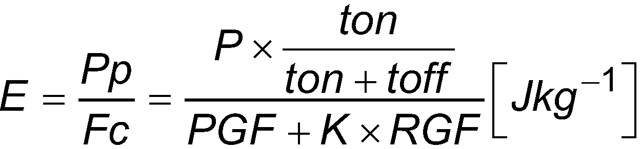
- E
- massebezogene Anregungsenergie (Energiedichte) [J/kg]
- Pp
- mittlere Pulsleistung [J/s]
- Fc
- korrigierter Prozessgasfluss [kg/s]
- P
- Leistung [J/s]
- ton
- Pulsanschaltzeit [s]
- toff
- Pulsausschaltzeit [s]
- PGF
- Präkursor-Massefluss [kg/s]
- RGF
- Reaktivgas-Massefluss [kg/s]
- E
- mass-related excitation energy (energy density) [J/kg]
- pp
- average pulse power [J/s]
- FC
- corrected process gas flow [kg/s]
- P
- Power [J/s]
- volume
- Pulse switch-on time [s]
- toff
- Pulse switch-off time [s]
- PGF
- Precursor mass flow [kg/s]
- RGF
- Reactive gas mass flow [kg/s]
In der bevorzugten Ausführungsform wird zur Abscheidung der Barrierezone bei relativ hohem Reaktivgasanteil, vorzugsweise mit 25 ≤ C ≤ 250, besonders bevorzugt mit 50 ≤ C ≤ 100, eine relativ hohe massebezogene Anregungsenergie zugeführt, vorzugsweise 400 kJ/kg ≤ E ≤ 2700 kJ/kg, besonders bevorzugt 1800 kJ/kg ≤ E ≤ 2200 kJ/kg.In the preferred embodiment, a relatively high mass-related excitation energy, preferably 400 kJ/kg ≦E≦2700 kJ/kg, is supplied to deposit the barrier zone with a relatively high proportion of reactive gas, preferably with 25≦C≦250, particularly preferably with 50≦C≦100 , particularly preferably 1800 kJ/kg≦E≦2200 kJ/kg.
Zur Abscheidung der Passivierungszone wird bei relativ niedrigem Reaktivgasanteil, vorzugsweise 0 ≤ C ≤ 20, besonders bevorzugt 0 ≤ C ≤ 10, eine relativ niedrige bis mittlere massebezogene Anregungsenergie zugeführt, vorzugsweise 30 kJ/kg ≤ E ≤ 1700 kJ/kg, besonders bevorzugt 500 kJ/kg ≤ E ≤ 800 kJ/kg.To deposit the passivation zone, a relatively low to medium mass-related excitation energy is supplied with a relatively low proportion of reactive gas, preferably 0 ≤ C ≤ 20, particularly preferably 0 ≤ C ≤ 10, preferably 30 kJ/kg ≤ E ≤ 1700 kJ/kg, particularly preferably 500 kJ/kg ≤ E ≤ 800 kJ/kg.
Zur Abscheidung der optionalen Haftzone wird bei relativ niedrigem bis mittleren Reaktivgasanteil, vorzugsweise 0 ≤ C ≤ 50, besonders bevorzugt 0 ≤ C ≤ 30, eine relativ niedrige massebezogene Anregungsenergie zugeführt, vorzugsweise 20 kJ/kg ≤ E ≤ 200 kJ/kg, besonders bevorzugt 30 kJ/kg ≤ E ≤ 140 kJ/kg.To deposit the optional adhesion zone, a relatively low mass-related excitation energy is supplied, preferably 20 kJ/kg ≦E ≦200 kJ/kg, particularly preferably, with a relatively low to medium reactive gas content, preferably 0≦C≦50, particularly preferably 0≦C≦30 30kJ/kg ≤ E ≤ 140kJ/kg.
Die hier genannten Intervallgrenzen sind sowohl in Kombination als auch jeweils für sich allein genommen offenbart und tragen zum technischen Effekt der Erfindung bei. So ist ausdrücklich auch die jeweils untere oder obere Grenze des Intervalls eigenständig offenbart.The interval limits mentioned here are disclosed both in combination and taken individually and contribute to the technical effect of the invention. The respective lower or upper limit of the interval is also expressly disclosed independently.
Ein weiterer Aspekt der Erfindung besteht darin, die Gradientenschicht, insbesondere die einzelnen Zonen, ausreichend dünn auszubilden. Die Gesamtdicke der Beschichtung liegt vorteilhafterweise unter 1000 Nanometer. Vorzugsweise ist die Beschichtung bis zu 500 Nanometer dick.A further aspect of the invention consists in making the gradient layer, in particular the individual zones, sufficiently thin. The total thickness of the coating is advantageously less than 1000 nanometers. Preferably the coating is up to 500 nanometers thick.
Eine dünne Beschichtung weist eine geringere Schichtspannung auf. Durch die geringere Schichtspannung wird das Risiko gesenkt, dass sich bei mechanischer Belastung Risse in der Beschichtung bilden oder die Beschichtung bricht. Im Gegensatz zu dickeren Gradientenschichten im Bereich der Kratzschutzschichten (z.B. für Brillengläser) sind die Anforderungen in Bezug auf die mechanische Belastbarkeit im Bereich der Kunststoffbehälter höher. Dünnwandige Kunststoffbehälter sind in der Regel weich. Bei der Lagerung oder dem Transport der Behälter kann es zu Verformungen des Behälters (z.B. bei Stößen oder beim Stapeln) kommen. Solche Verformungen dürfen nicht zum Versagen der Beschichtung führen. Es zeigt sich, dass dünne Beschichtungen mit einer Dicke unter 1000 Nanometer, vorzugsweise unter 500 Nanometer, besonders gut für Kunststoffbehälter, insbesondere zur Lagerung aggressiver Medien, geeignet sind.A thin coating has a lower layer stress. The lower layer tension reduces the risk of cracks forming in the coating or the coating breaking under mechanical stress. In contrast to thicker gradient layers in the area of scratch protection layers (e.g. for spectacle lenses), the requirements in terms of mechanical strength are higher in the area of plastic containers. Thin-walled plastic containers are usually soft. When storing or transporting the containers, the containers may become deformed (e.g. if they are bumped or stacked). Such deformations must not lead to failure of the coating. It has been shown that thin coatings with a thickness of less than 1000 nanometers, preferably less than 500 nanometers, are particularly well suited for plastic containers, in particular for storing aggressive media.
Auch die in der Gradientenschicht gebildeten Zonen weisen vorzugsweise eine für deren Funktion und/oder den Schichtbildungsprozess optimierte Dicke auf.The zones formed in the gradient layer preferably also have a thickness that is optimized for their function and/or the layer formation process.
Die Dicke der optionalen Haftzone beträgt vorzugsweise maximal 10 Nanometer. Die Haftzone ist vorzugsweise dünner als die Barrierezone oder die Passivierungszone. Eine derart dünne Haftzone reicht aus, um das Kunststoffsubstrat vor dem oxidativ degradativen Einfluss des sauerstoffreichen Plasmas zur Abscheidung der Barrierezone zu schützen. Bei steigender Dicke der Haftzone kann es bei der Abscheidung der darauffolgenden Barrierezone zu verstärkter Porenbildung kommen. Eine dünne Haftzone von maximal 10 Nanometer Dicke ist daher vorteilhaft für eine homogene Schichtbildung. Eine solch dünne Haftzone bildet eine möglichst homogene Grundlage zur Abscheidung der darauffolgenden Barrierezone.The thickness of the optional adhesion zone is preferably a maximum of 10 nanometers. The adhesion zone is preferably thinner than the barrier zone or the passivation zone. Such a thin adhesion zone is sufficient to protect the plastic substrate from the oxidative-degradative influence of the oxygen-rich plasma used to deposit the barrier zone. With increasing thickness of the adhesion zone, increased pore formation can occur during the deposition of the subsequent barrier zone. A thin adhesion zone with a maximum thickness of 10 nanometers is therefore advantageous for homogeneous layer formation. Such a thin adhesion zone forms a basis that is as homogeneous as possible for the deposition of the subsequent barrier zone.
Die Barrierezone hat vorzugsweise eine maximale Dicke von 100 Nanometer. Die dünne Barrierezone reicht aus, um eine ausreichende Migrationsbarriere zu bilden. Gleichzeitig ist ein homogenes Schichtwachstum möglich. Vorzugsweise ist die Barrierezone dünner als die Passivierungszone ausgebildet. Eine dünnere Barrierezone ist vorteilhaft für ein rissfreies Schichtwachstum.The barrier zone preferably has a maximum thickness of 100 nanometers. The thin barrier zone is sufficient to form an adequate migration barrier. At the same time, a homogeneous layer growth is possible. The barrier zone is preferably thinner than the passivation zone. A thinner barrier zone is advantageous for crack-free layer growth.
Hochoxidierte Schichten wachsen mit intrinsischen Schichtspannungen auf. Die organisch geprägte Passivierungsschicht wächst hingegen nahezu frei von Schichtspannungen und kann daher auch dicker ausgebildet sein.Highly oxidized layers grow with intrinsic layer stresses. The organically shaped passivation layer, on the other hand, grows almost free of layer stresses and can therefore also be made thicker.
Die Passivierungszone hat eine bevorzugte Dicke von bis zu 800 Nanometer. Da die Passivierungszone einen ausreichenden Schutz der Barrierezone vor dem Einfluss der aggressiven Medien im Behälter gewährleisten muss, kann die Passivierungszone dicker ausgebildet werden als die Barrierezone.The passivation zone has a preferred thickness of up to 800 nanometers. Since the passivation zone must ensure adequate protection of the barrier zone against the influence of aggressive media in the container, the passivation zone can be made thicker than the barrier zone.
Die Beschichtung kann aus einer oder mehreren Gradientenschichten aufgebaut werden. Der oben beschriebene Aufbau der Gradientenschicht kann zur Verstärkung der Schutzwirkung in mehreren zusammenhängenden Gradientenschichten wiederholt werden. Eine am Rand der Beschichtung liegende Zone hat ihren organischen bzw. oxidischen Schwerpunkt in der Regel am äußeren, d.h. dem Medium bzw. dem Substrat zugewandten, Ende. Eine im Inneren einer Gradientenschicht angeordnete Zone hat in der Regel einen mittig liegenden oxidischen bzw. organischen Schwerpunkt.The coating can be built up from one or more gradient layers. The structure of the gradient layer described above can be repeated in several coherent gradient layers to increase the protective effect. A zone at the edge of the coating usually has its organic or oxidic focus at the outer end, i.e. the end facing the medium or the substrate. A zone arranged in the interior of a gradient layer generally has an oxidic or organic focus in the middle.
Im Gegensatz zum konsekutiven Auftrag verschiedener Schichttypen in einer Verbundschicht findet das Beschichtungsmaterial bei einer Gradientenschicht immer eine chemisch ähnliche Oberfläche vor, sodass Lagenwachstum begünstigt und die Ausbildung von Poren an zusammenwachsenden Inseln verhindert wird.In contrast to the consecutive application of different layer types in a composite layer, the coating material in a gradient layer always has a chemically similar surface, so that layer growth is promoted and the formation of pores on islands growing together is prevented.
Die Anpassung der Gasflüsse, d.h. die Zusammensetzung des Prozessgasgemischs, erlaubt die Einstellung der benötigten chemischen Zusammensetzung von Barriere- und Passivierungszonen. Durch die gezielte Kontrolle der pro Molekül eingebrachten Energie in Abhängigkeit vom Prozessgasgemisch wird weiterhin Volumenpolymerisation unterbunden, um zu verhindern, dass große Oligomere an der Schichtbildung teilnehmen und Poren erzeugen können.Adjusting the gas flows, i.e. the composition of the process gas mixture, allows the required chemical composition of barrier and passivation zones to be set. Through the targeted control of the energy introduced per molecule depending on the process gas mixture, volume polymerization is also suppressed in order to prevent large oligomers from taking part in the layer formation and being able to create pores.
Mithilfe des erfindungsgemäßen Verfahrens lassen sich somit Schichten erzeugen, die über eine hohe Barriereleistung gegen Gase und andere Permeanten und gleichzeitig über eine hohe Stabilität gegen aggressive Medien oder andere Umwelteinflüsse verfügen, da die oberen Schichten chemisch stabil und zugleich porenfrei sind.The method according to the invention can thus be used to produce layers that have a high barrier performance against gases and other permeants and at the same time have high stability against aggressive media or other environmental influences, since the upper layers are chemically stable and at the same time non-porous.
Für mit den Gradientenschichten beschichtete Behälter aus Polyethylen können in Abhängigkeit von Oberflächengüte, Volumen und Gewicht der Behälter Barriereverbesserungen von Faktor 50 bis 2000, bezogen auf die Sauerstoffpermeationsrate, erzielt werden. Ferner bleiben die Gradientenschichten auch nach längerer Lagerung von hochalkalischer NaOH-Lösung oder ähnlicher aggressiver Chemikalien beständig und die Barriere bleibt erhalten. Damit können sie dazu eingesetzt werden, Verpackungen aus klassischen Verpackungskunststoffen wie PE oder PET zur Lagerung sensibler Chemikalien einsetzbar zu machen.Depending on the surface quality, volume and weight of the containers, barrier improvements of a factor of 50 to 2000, based on the oxygen permeation rate, can be achieved for containers made of polyethylene coated with the gradient layers. Furthermore, the gradient layers remain stable and the barrier is retained even after prolonged storage of highly alkaline NaOH solution or similar aggressive chemicals. They can therefore be used to make packaging made of classic packaging plastics such as PE or PET suitable for storing sensitive chemicals.
Anstelle von Silizium sind für den Einsatz der Erfindung auch andere geeignete Halbmetalle oder Metalle denkbar. Die Erfindung ist nicht auf siliziumbasierte Ausgangsstoffe bzw. Beschichtungen beschränkt. Alternativ oder zusätzlich zu den bevorzugten Präkursoren HMDSO und HMDSN können auch andere (halb-)metallische Monomere eingesetzt werden. Auch können alternativ oder zusätzlich zu Sauerstoff andere Reaktivgase, z.B. Stickstoff, eingesetzt werden. Die Offenbarung umfasst auch solche Ausführungsformen, in denen anstatt der bevorzugten Prozessgase, die hier genannten oder dem Fachmann für PECVD bekannten Alternativen eingesetzt werden.Instead of silicon, other suitable semi-metals or metals are also conceivable for the use of the invention. The invention is not limited to silicon-based starting materials or coatings. As an alternative or in addition to the preferred precursors HMDSO and HMDSN, other (semi)metallic monomers can also be used. Other reactive gases, for example nitrogen, can also be used as an alternative or in addition to oxygen. The disclosure also includes such embodiments in which instead of the preferred process gases, the alternatives mentioned here or known to those skilled in the art for PECVD are used.
Weitere vorteilhafte Ausführungsformen werden nachfolgend anhand der Zeichnungen beschrieben.Further advantageous embodiments are described below with reference to the drawings.
Die Erfindung ist in den Zeichnungen beispielhaft und schematisch dargestellt. Es zeigen:
-
1 : Aufbau eines Reaktors; -
2 : Aufbau einer Gradientenschicht (3-Zonen-Schicht); -
3 : Aufbau einer Beschichtung mit mehreren Gradientenschichten; -
4 : Vorteilhafter Verlauf der Prozessparameter C und E während der Abscheidung einer Gradientschicht; -
5 : FT-IR Spektren an den Schwerpunkten einer Haftzone (EH) und einer Barrierezone (WB); -
6 : FT-IR Spektren am Schwerpunkt einer Passivierungszone.
-
1 : structure of a reactor; -
2 : Structure of a gradient layer (3-zone layer); -
3 : structure of a coating with several gradient layers; -
4 : Advantageous course of the process parameters C and E during the deposition of a gradient layer; -
5 : FT-IR spectra at the centroids of a sticking zone (EH) and a barrier zone (WB); -
6 : FT-IR spectra at the centroid of a passivation zone.
Über Leitungen wird ein Prozessgasgemisch (PGM) in den Reaktionsraum (302) geführt. Der Reaktor umfasst eine Gasversorgung (320) sowie einen oder mehrere Gasflussregler (321), vorzugsweise Masseflussregler. Das Prozessgasgemisch (PGM) setzt sich aus einem oder mehreren Prozessgasen (PG1, PG2, RG) zusammen, deren Mischverhältnisse geregelt werden können.A process gas mixture (PGM) is fed into the reaction chamber (302) via lines. The reactor comprises a gas supply (320) and one or more gas flow controllers (321), preferably mass flow controllers. The process gas mixture (PGM) consists of one or more process gases (PG1, PG2, RG) whose mixing ratios can be regulated.
In der bevorzugten Ausführungsform werden zwei Präkursoren eingesetzt. Der erste Präkursor (PG1) ist vorzugsweise HMDSN. Der zweite Präkursor (PG2) ist vorzugsweise HDMSO.In the preferred embodiment, two precursors are used. The first precursor (PG1) is preferably HMDSN. The second precursor (PG2) is preferably HDMSO.
Ein oder mehrere Präkursoren (PG1, PG2) können insbesondere für eine bestimmte Zone der Gradientenschicht eingesetzt werden. Es ist insbesondere vorteilhaft für die Abscheidung der Haftzone (201) und/oder der Passivierungszone (203) (überwiegend) HMDSO als einen ersten Präkursor einzusetzen. Alternativ oder zusätzlich ist es besonders vorteilhaft für die Abscheidung der Barrierezone (202) (überwiegend) HMDSN als zweiten Präkursor einzusetzen.One or more precursors (PG1, PG2) can be used in particular for a specific zone of the gradient layer. It is particularly advantageous to use (predominantly) HMDSO as a first precursor for the deposition of the adhesion zone (201) and/or the passivation zone (203). Alternatively or additionally, it is particularly advantageous to use (predominantly) HMDSN as the second precursor for the deposition of the barrier zone (202).
Insbesondere im Übergang zwischen zwei Zonen der Gradientenschicht können zumindest vorrübergehend zwei oder mehr Präkursoren gemischt werden.In particular, in the transition between two zones of the gradient layer, two or more precursors can be mixed at least temporarily.
Der Präkursormassefluss ist vorzugsweise auf die Summe der Masseflüsse der mehreren Präkursoren bezogen. Bei chemisch ähnlichen Präkursoren (z.B. HMDSN und HMDSO) können die Masseflüsse der einzelnen Präkursoren im Prozessgasgemisch für die Bestimmung der massebezogenen Anregungsenergie zu einem rechnerischen Präkursormassefluss zusammengefasst werden. In manchen Ausführungsformen kann es zweckmäßig sein, die einzelnen Gasmasseflüsse mit einem Faktor zu gewichten.The precursor mass flow is preferably related to the sum of the mass flows of the multiple precursors. In the case of chemically similar precursors (e.g. HMDSN and HMDSO), the mass flows of the individual precursors in the process gas mixture can be combined into a calculated precursor mass flow to determine the mass-related excitation energy. In some embodiments it can be useful to weight the individual gas mass flows with a factor.
Als Reaktivgas (RG) wird vorzugsweise Sauerstoff eingesetzt. Alternativ oder zusätzlich kann Stickstoff als (weiteres) Reaktivgas (RG) eingesetzt werden.Oxygen is preferably used as the reactive gas (RG). Alternatively or additionally, nitrogen can be used as a (further) reactive gas (RG).
Im Reaktionsraum (302) wird das Prozessgasgemisch (PGM) mittels einer Energiequelle (350) angeregt. Vorzugsweise wird als Energiequelle (350) ein Magnetron eingesetzt. Die Anregung der Plasmas erfolgt vorzugsweise durch gepulste Mikrowellen (351). Alternativ oder zusätzlich können auch ICP-Plasmen eingesetzt werden.The process gas mixture (PGM) is excited in the reaction space (302) by means of an energy source (350). A magnetron is preferably used as the energy source (350). The plasma is preferably excited by pulsed microwaves (351). Alternatively or additionally, ICP plasmas can also be used.
Aus dem zum Plasma (352) angeregten Prozessgasgemisch wird die Beschichtung (200) auf dem Kunststoffbehälter (100) abgeschieden.The coating (200) is deposited on the plastic container (100) from the process gas mixture excited to form the plasma (352).
Die Prozesskammer (301) kann einen oder mehrere Reaktionsräume (302) umfassen. Der Reaktionsraum (302) kann die gesamte Prozesskammer oder nur einen Teil beanspruchen. Insbesondere kann der Reaktionsraum (302) im Inneren des Kunststoffbehälters (100) gebildet werden. Vorzugsweise ist der Behälter abgedichtet. Alternativ oder zusätzlich kann ein weiterer Reaktionsraum, z.B. an der Außenseite des Behälters, gebildet werden.The process chamber (301) can include one or more reaction spaces (302). The reaction space (302) can occupy the entire process chamber or only a part. In particular, the reaction space (302) can be formed inside the plastic container (100). Preferably the Container sealed. Alternatively or additionally, a further reaction space can be formed, for example on the outside of the container.
Der Reaktor (300) kann auch mehrere Prozesskammern (301) mit einem oder mehreren Reaktionsräumen (302) umfassen.The reactor (300) can also include multiple process chambers (301) with one or more reaction spaces (302).
Die Abscheidung der Beschichtung (200) erfolgt je nach Aufbau der Schicht, Größe des Substrats (100) und Prozessführung vorzugsweise über einen Zeitraum von ca. 5 - 60 Sekunden. Bei besonders großen Behältern kann es auch zu längeren Prozesszeiten kommen. Während des Abscheideprozesses wird mindestens eine Gradientenschicht abgeschieden.Depending on the structure of the layer, the size of the substrate (100) and the process control, the coating (200) is preferably deposited over a period of approximately 5-60 seconds. In the case of particularly large containers, the process times can also be longer. At least one gradient layer is deposited during the deposition process.
Während des Verfahrens wird das Mischverhältnis des Prozessgasgemischs (PGM) verändert. Insbesondere wird der Masseflussanteil der Präkursoren (PG1, PG2) und/oder des Reaktivgases (RG) verändert. Durch die Variation der Prozessgase wird die stoffliche Zusammensetzung der Beschichtung (200) beeinflusst.During the process, the mixing ratio of the process gas mixture (PGM) is changed. In particular, the mass flow fraction of the precursors (PG1, PG2) and/or the reactive gas (RG) is changed. The material composition of the coating (200) is influenced by the variation of the process gases.
Eine vorteilhafter Verlauf der Prozessparameter ist in
Vorzugsweise wird der Reaktivgasanteil (C) und/oder die massebezogene Anregungsenergie (E) zwischen der Haftzone (201) und der Barrierezone (202) in Schichtaufbaurichtung (x) graduell erhöht.Preferably, the proportion of reactive gas (C) and/or the mass-related excitation energy (E) is gradually increased between the adhesion zone (201) and the barrier zone (202) in the layer structure direction (x).
Alternativ oder zusätzlich wird der Reaktivgasanteil (C) und/oder die massebezogene Anregungsenergie (E) zwischen der Barrierezone (202) und der Passivierungszone (203) in Schichtaufbaurichtung (x) graduell gesenkt.Alternatively or additionally, the proportion of reactive gas (C) and/or the mass-related excitation energy (E) between the barrier zone (202) and the passivation zone (203) is gradually reduced in the layer structure direction (x).
Die Variation des Reaktivgasanteils (C) und der massebezogenen Anregungsenergie (E) erfolgt vorzugsweise gleichmäßig, insbesondere stufenlos.The reactive gas fraction (C) and the mass-related excitation energy (E) are preferably varied uniformly, in particular steplessly.
Besonders vorteilhafterweise wird die Anregungsenergie (E) in Abhängigkeit der Zusammensetzung des Prozessgasgemischs (PGM), insbesondere in Abhängigkeit des Präkursorgasmasseflusses und/oder des Reaktivgasmasseflusses, gesteuert.The excitation energy (E) is particularly advantageously controlled as a function of the composition of the process gas mixture (PGM), in particular as a function of the precursor gas mass flow and/or the reactive gas mass flow.
Zur Steuerung der massebezogenen Anregungsenergie stehen dem Fachmann mehrere Möglichkeiten zur Verfügung. Insbesondere kann die mittlere Pulsleistung eingestellt werden. Vorteilhafterweise werden die Leistung der Energiequelle und/oder die Pulsparameter geregelt. Es ist insbesondere vorteilhaft einen Sollwert für die massebezogene Anregungsenergie (E) zu berechnen und diese mit einer oder mehreren Stellgrößen, z.B. eine Auswahl oder Kombination aus (Nenn-)Leistungszufuhr, Pulsanschaltzeit, Pulsausschaltzeit oder Pulsrate, zu steuern oder zu regeln.A person skilled in the art has several options for controlling the mass-related excitation energy. In particular, the average pulse power can be adjusted. The power of the energy source and/or the pulse parameters are advantageously regulated. It is particularly advantageous to calculate a target value for the mass-related excitation energy (E) and to control or regulate this with one or more manipulated variables, e.g. a selection or combination of (nominal) power supply, pulse switch-on time, pulse switch-off time or pulse rate.
Die Dicke einer geeigneten Beschichtung (d) liegt vorzugsweise im Bereich zwischen 80 - 1000 Nanometer. Das Kunststoffsubstrat (100) ist um mehrere Größenordnungen dicker. Übliche Wandstärken für Kunststoffbehälter liegen im Millimeter-Bereich. Zur gemeinsamen Darstellbarkeit ist das Kunststoffsubstrat daher gebrochen dargestellt.The thickness of a suitable coating (d) is preferably in the range between 80-1000 nanometers. The plastic substrate (100) is several orders of magnitude thicker. The usual wall thicknesses for plastic containers are in the millimeter range. The plastic substrate is therefore shown broken so that it can be shown together.
Bei einer 3-Zonen-Schicht (
Bei einer 2-Zonen-Schicht kann die Barrierezone (202) auch direkt auf dem Substrat abgeschieden werden.In the case of a 2-zone layer, the barrier zone (202) can also be deposited directly on the substrate.
Die Gradientenschicht (200') umfasst zumindest eine Barrierezone (202) und eine Passivierungszone (203). Die Passivierungszone (203) ist zwischen der Umgebungsseite (211) der Beschichtung (200) und der Barrierezone (202) angeordnet. Die Passivierungszone (203) schützt die Barrierezone (202). Die Passivierungszone ist beständig gegen den Einfluss aggressiver Medien (M).The gradient layer (200') comprises at least one barrier zone (202) and one passivation zone (203). The passivation zone (203) is arranged between the surrounding side (211) of the coating (200) and the barrier zone (202). The passivation zone (203) protects the barrier zone (202). The passivation zone is resistant to the influence of aggressive media (M).
Die Beschichtung (200) bildet eine Migrationsbarriere, d.h. auch Diffusionssperre, für Umgebungsgase (A), die durch das Kunststoffsubstrat (100) hindurch diffundieren können. Durch die Bildung einer oder mehrerer Barrierezonen (202) werden Permeationswege unterbrochen. Die oxidische Barrierezone (202) wirkt als Migrationsbarriere. The coating (200) forms a migration barrier, ie also a diffusion barrier, for ambient gases (A) which can diffuse through the plastic substrate (100). Permeation paths are interrupted by the formation of one or more barrier zones (202). The oxidic barrier zone (202) acts as a migration barrier.
Die Gradientenschicht (200') wird während des Abscheideprozesses in einer Vielzahl von Nanolagen (L) aufgebaut. Die stoffliche Zusammensetzung der einzelnen Nanolagen (L) verändert sich in Schichtaufbaurichtung (x) graduell.The gradient layer (200') is built up in a large number of nanolayers (L) during the deposition process. The material composition of the individual nanolayers (L) changes gradually in the layer structure direction (x).
Der Gradient (G) zeigt schematisch den graduellen Verlauf der stofflichen Zusammensetzung der Gradientenschicht.The gradient (G) schematically shows the gradual course of the material composition of the gradient layer.
Die einzelnen Zonen, d.h. die Haftzone (201), die Barrierezone (202) und die Passivierungszone (203), lassen sich anhand deren stofflichen Zusammensetzung und des Anteils bestimmter Bindungstypen beschreiben. Repräsentativ für die sich graduell verändernde Zusammensetzung in einer bestimmten Zone kann der jeweilige Schwerpunkt der Zone betrachtet werden. Der jeweilige Schwerpunkt (S1, S2, S3) einer Zone kann als eine bestimmte Nanolage (L) an einem Extremum eines bestimmten Eigenschaftsverlaufs, z.B. des Gradienten (G), entlang der Schichtaufbaurichtung (x) betrachtet werden.The individual zones, i.e. the adhesion zone (201), the barrier zone (202) and the passivation zone (203), can be described on the basis of their material composition and the proportion of certain bond types. The respective center of gravity of the zone can be considered as representative of the gradually changing composition in a certain zone. The respective focal point (S1, S2, S3) of a zone can be viewed as a specific nanolayer (L) at an extremum of a specific property profile, e.g. the gradient (G), along the layer structure direction (x).
Die chemische Struktur der Gradientenschichten wird definiert durch die Extrema (Schwerpunkte), insbesondere lokale oder globale Maxima bzw. Minima, an denen sich die für den jeweiligen Schichttyp maximalen Schichteigenschaften eingestellt haben, sodass sich die Prozessführung fortan zur Erreichung des nächsten Extremums ausrichtet. Die chemische Struktur an den Extrempunkten (S1, S2, S3) wird im Folgenden näher beschrieben. Die Tabelle 1 gibt jeweils bevorzugte elementare Zusammensetzungen der Schichten an den Extrema an, die jeweils mittels Röntgenphotoelektronenspektroskopie (englisch: X-ray photoelectron spectroscopy, XPS) ermittelt wurden. 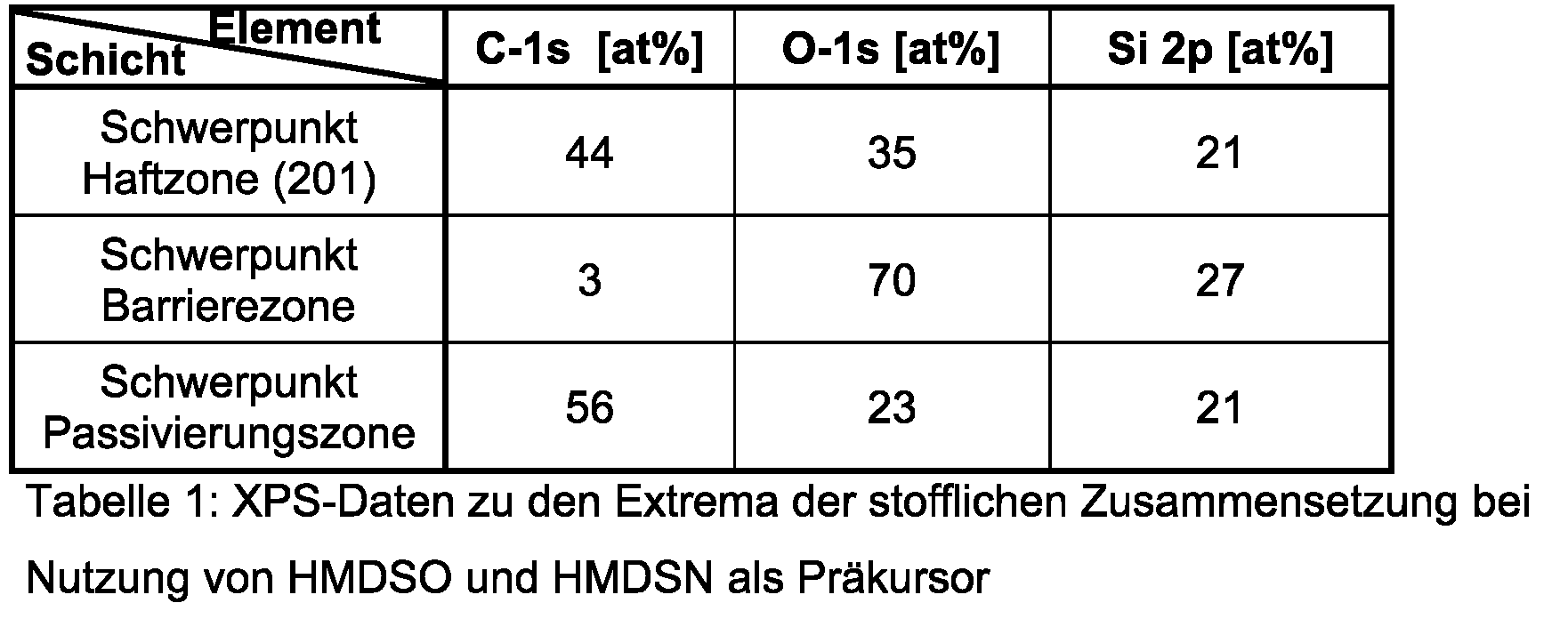
Um die chemische Struktur der verschiedenen Zonen, vor allem die der Schwerpunkte der jeweiligen Zonen, weiter zu charakterisieren, wird Fourier-Transform-Infrarotspektroskopie (FT-IR) eingesetzt. In Tabelle 2 sind die für die Auswertung der FTIR-Messungen wichtigen Vibrationsmodi aufgelistet. Tabelle 2: Vibrationsmodus und FT-IR Peak-Position
In Tabelle 2 bezeichnen die Präfixe: s = stretching; b = bending; r = rocking; sowie das Subskript: sym = symmetrisch.In Table 2, the prefixes denote: s = stretching; b = bending; r = rocking; and the subscript: sym = symmetric.
Die Beschichtung am Extremum der Barrierezone (WB), vgl. Schwerpunkt S2 in
Die Intensität und genaue Peak-Position des Peaks des Si-O-Si Netzwerks liefert Informationen über den Vernetzungsgrad der Schichten. Eine höhere Peak-Maximalposition zeigt eine höhere Si-O-Si-Vernetzung an. Eine solche Peakverschiebung ist im Vergleich der beiden Spektren deutlich zu erkennen. Bei der Barrierezone (WB) liegt eine hochvernetzte Beschichtung mit ausgeprägter Si-O-Si-Netzwerkstruktur vor, in welcher wenig C und C-H gebunden sind.The intensity and precise peak position of the Si-O-Si network peak provides information about the degree of crosslinking of the layers. A higher peak maximum position indicates higher Si-O-Si crosslinking. Such a peak shift can be clearly seen when comparing the two spectra. In the barrier zone (WB) there is a highly cross-linked coating with a pronounced Si-O-Si network structure in which little C and C-H are bonded.
Das Spektrum der Passivierungszone in
Die chemische Struktur der Zonen ist vor allem in Bezug auf die Barriereleistung der Barrierezone sowie die Hydrolysestabilität der Passivierungszone von herausragender Bedeutung.The chemical structure of the zones is of outstanding importance, especially with regard to the barrier performance of the barrier zone and the hydrolysis stability of the passivation zone.
Zur Charakterisierung der chemischen Struktur der Zonen wird daher ferner der Strukturparameter V eingeführt, der das Verhältnis aus den Flächen (Gauß-Kurven) unter den mittels FT-IR gemessenen Peaks darstellt, die jeweils eindeutig CH3- oder Si-O-Gruppen zugeordnet werden können (Die Zuordnung der Peaks kann Tabelle 2 entnommen werden):![]()
- V:
- Strukturparameter [-]
- A:
- Extinktion X [-] an W = 1376 cm-1
- B:
- Extinktion X [-] an W = 1257 cm-1
- E:
- Extinktion X [-] an W = 839 cm-1
- C:
- Extinktion X [-] an W = 440 cm-1, 1010 cm-1 bis 1035 cm-1, 1070 cm-1
- D:
- Extinktion X [-] an W = 930 cm-1
- V:
- Structural parameters [-]
- A:
- absorbance X [-] at W = 1376 cm -1
- B:
- absorbance X [-] at W = 1257 cm -1
- E:
- absorbance X [-] at W = 839 cm -1
- C:
- Absorbance X [-] at W = 440 cm -1 , 1010 cm -1 to 1035 cm -1 , 1070 cm -1
- D:
- absorbance X [-] at W = 930 cm -1
Die Barriereleistung der Barrierezone wird hinsichtlich der chemischen Struktur vor allem vom Vernetzungs- und Oxidationsgrad der Schichten bestimmt. Für das Extremum der Barrierezone (WB) wurde ein vorteilhafter Bereich von V < 0,2 und ein besonders vorteilhafter Bereich von V < 0,05 bestimmt.With regard to the chemical structure, the barrier performance of the barrier zone is primarily determined by the degree of crosslinking and oxidation of the layers. An advantageous range of V < 0.2 and a particularly advantageous range of V < 0.05 were determined for the extremum of the barrier zone (WB).
Die chemische Beständigkeit der Passivierungszone wird erklärt durch eine Betrachtung der Elektronegativität der beteiligten Elemente im Schichtmaterial, über die die lokalen Partialladungsverschiebungen der Bindungen bewertet werden kann. Je höher die Differenz der Elektronegativität der Bindungspartner ist, desto stärker sind die Bindungselektronen an den Bindungspartner mit höherer Elektronegativität lokalisiert. Dadurch erfährt dieses Element einen Elektronenschub.The chemical stability of the passivation zone is explained by considering the electronegativity of the elements involved in the layer material, which can be used to evaluate the local partial charge shifts in the bonds. The higher the difference in electronegativity of the binding partners, the stronger the binding electrons are localized to the binding partner with higher electronegativity. As a result, this element experiences an electron boost.
Unter den in den Schichten vorhandenen Bindungen erfährt somit vor allem der Sauerstoff in Si-O den größten Elektronenschub. Dadurch tragen Sauerstoff negative (δ-) und das Silizium positive Partialladungen (δ+). Das Silizium erfährt also einen Elektronenmangel. Negativ geladene Ionen in Lösung greifen daher das mit Sauerstoff gebundene Silizium aufgrund dessen positiver Partialladungen an. Si-CH3 Bindungen verfügen wiederum über geringe Partialladungen. Die Schicht wird also beispielsweise an Si-O vom Ion nukleophil angegriffen. Es resultieren Si-OH-Bindungen unter dem Bindungsbruch der Si-O-Si-Bindung. Innerhalb des Si-O Netzwerkes entstehen somit immer mehr Lücken unter Einbringung anionischer Endgruppen. Durch die CH3-Gruppen werden schwache Bindungen sterisch abgeschirmt, was die Reaktion deutlich verlangsamt oder gänzlich aufhalten kann. Je größer das Verhältnis von CH3-Gruppen zu Si-O ist, desto langsamer kann der Abbau der Schicht voranschreiten. Je größer V, desto beständiger die Beschichtung. Für das Extremum der Passivierungszone wird vorzugsweise mindestens ein Strukturparameter V > 0,20 und besonders vorteilhaft ein V > 0,35 erreicht, um die notwendige Schutzleistung bereitstellen zu können.Among the bonds present in the layers, it is above all the oxygen in Si-O that experiences the greatest electron boost. As a result, oxygen carries negative (δ - ) and silicon carries positive partial charges (δ + ). The silicon thus experiences a lack of electrons. Negatively charged ions in solution therefore attack the oxygen-bound silicon due to its positive partial charges. Si-CH 3 bonds in turn have low partial charges. The layer is therefore nucleophilically attacked by the ion at Si—O, for example. Si-OH bonds result under the bond breaking of the Si-O-Si bond. More and more gaps are thus created within the Si-O network with the introduction of anionic end groups. The CH 3 groups sterically shield weak bonds, which can significantly slow down the reaction or stop it entirely. The greater the ratio of CH 3 groups to Si—O, the slower the degradation of the layer can progress. The larger V, the more durable the coating. For the extremum of the passivation zone, preferably at least one structure parameter V>0.20 and particularly advantageously V>0.35 is achieved in order to be able to provide the necessary protective performance.
Zur Abscheidung einer vorteilhaften Haftvermittlerschicht wird am Extremum der Haftvermittlerzone (EH) ein Strukturparameter V von 0,1 < V < 0,3 erreicht.In order to deposit an advantageous adhesion promoter layer, a structural parameter V of 0.1<V<0.3 is achieved at the extremum of the adhesion promoter zone (EH).
Der Strukturparameter V kann zur Ermittlung der oxidischen bzw. organischen Schwerpunkte und/oder der funktionalen Zonen einer Gradientenschicht genutzt werden. In
Der jeweilige oxidische bzw. organische Schwerpunkt einer Zone kann je nach Schichtarchitektur am Rand oder in der Mitte der Zone liegen. Die Übergänge zwischen den Zonen sind fließend.Depending on the layer architecture, the respective oxidic or organic focus of a zone can be at the edge or in the middle of the zone. The transitions between the zones are fluid.
Die Zonen werden vorzugsweise durch ihre stoffliche Zusammensetzung bestimmt. Die stoffliche Zusammensetzung der einzelnen Nanolagen bestimmt die Funktion der Schichtzonen.The zones are preferably determined by their material composition. The material composition of the individual nanolayers determines the function of the layer zones.
Zur Abgrenzung der Zonen (201, 202, 203), z.B. der Bestimmung der Dicken (d1, d2, d3), können verschiedene Analysearten herangezogen werden. Beispielsweise kann die stoffliche Zusammensetzung der einzelnen Nanolagen im SIMS-Verfahren (Sekundärionen-Massenspektrometrie) oder ferner im nanoSIMS-Verfahren bestimmt werden. Durch lonenbeschuss der Oberfläche können die Schichten in Nanometerauflösung abgetragen werden und analysiert werden.Various types of analysis can be used to delimit the zones (201, 202, 203), e.g. to determine the thicknesses (d1, d2, d3). For example, the material composition of the individual nanolayers can be determined using the SIMS method (secondary ion mass spectrometry) or also using the nanoSIMS method. By bombarding the surface with ions, the layers can be removed and analyzed in nanometer resolution.
Zur Definition der Dicke der Zonen kann der Strukturparameter V oder die elementare Zusammensetzung der Nanolagen entlang der Schichtaufbaurichtung ermittelt werden. Überwiegt der Anteil an organischen Verbindungen, kann die Lage der Passivierungs- bzw. Haftzone zugeordnet werden. Überwiegen oxidische Verbindungen kann die Lage der Barrierezone zugeordnet werden.To define the thickness of the zones, the structure parameter V or the elementary composition of the nanolayers can be determined along the layer structure direction. If the proportion of organic compounds predominates, the position can be assigned to the passivation or adhesion zone. Predominately oxidic compounds can be assigned to the location of the barrier zone.
Die stoffliche Zusammensetzung zweier benachbarter Nanolagen (L) ist stets ähnlich. Durch die stoffliche Ähnlichkeit der einzelnen Nanolagen (L) wird ein homogenes Lagenwachstum begünstigt.The material composition of two neighboring nanolayers (L) is always similar. The material similarity of the individual nanolayers (L) promotes homogeneous layer growth.
Der Vorteil des graduellen Aufbaus der Zonen der Gradientenschicht ist, dass während der Abscheidung jede Nanolage (L) eine chemisch ähnliche Grundlage findet. Die chemischen Eigenschaften der Nanolagen ändern sich nur allmählich. Hierdurch wird Inselwachstum verhindert.The advantage of the gradual build-up of the zones of the gradient layer is that during the deposition each nanolayer (L) finds a chemically similar basis. The chemical properties of the nanolayers change only gradually. This prevents island growth.
Der mehrlagige Aufbau der Gradientenschichten kann insbesondere vorteilhaft sein, um die Migrationssperre und/oder die chemische Beständigkeit, d.h. den Schutz der Barrierezone, zu verstärken. Alternativ oder zusätzlich können dabei dennoch die geringen Dicken der einzelnen Zonen eingehalten werden, wodurch das homogene Lagenwachstum und die mechanischen Eigenschaften (z.B. niedrige Schichtspannungen) der Beschichtung begünstigt werden.The multi-layer structure of the gradient layers can be particularly advantageous in order to increase the migration barrier and/or the chemical resistance, i.e. the protection of the barrier zone. Alternatively or additionally, the small thicknesses of the individual zones can still be maintained, which favors the homogeneous layer growth and the mechanical properties (e.g. low layer stresses) of the coating.
In einer nicht eigens dargestellten Ausführungsform kann die Beschichtung (200) auch eine Gradientenschicht (200''') mit nur einer Barrierezone (202) und einer Passivierungszone (203) umfassen. Insbesondere für PET-Substrate kann die Haftzone (201) entfallen.In an embodiment that is not shown specifically, the coating (200) can also include a gradient layer (200''') with only one barrier zone (202) and one passivation zone (203). The adhesive zone (201) can be omitted, in particular for PET substrates.
Bei einer 2-Zonen-Schicht (200''') ist die Barrierezone (202) vorzugsweise direkt auf dem Kunststoffsubstrat (100) oder auf einer dazwischenliegenden Gradientenschicht (200', 200") angeordnet. Bei einer 2-Zonen-Schicht kann die Barrierezone (202) insbesondere einen am Rand der Zone liegenden oxidischen Schwerpunkt aufweisen.In the case of a 2-zone layer (200''), the barrier zone (202) is preferably arranged directly on the plastic substrate (100) or on an intermediate gradient layer (200', 200"). In the case of a 2-zone layer, the Barrier zone (202) have in particular an oxidic focus lying at the edge of the zone.
Die Prozessgrößen C und E können insbesondere jeweils in einem bestimmten Prozessfenster (W) gesteuert oder geregelt werden.The process variables C and E can in particular each be controlled or regulated in a specific process window (W).
Die Haftzone (201) wird mit einem geringen bis mittleren Reaktivgasanteil (C) abgeschieden. In einer vorteilhaften Ausführungsform wird zu Beginn des Prozesses ein zumindest geringer Sauerstoffanteil beigemischt. Durch das entstehende sauerstoffreiche Plasma wird die Oberfläche des Kunststoffsubstrats (210) aktiviert. Auf diese Weise kann eine vorhergehende Oberflächenaktivierung des Substrats (100) entfallen, wodurch die Prozesszeiten verkürzt werden können. Die Aktivierung der Oberfläche verbessert die Haftung der Beschichtung (200) auf der Substratoberfläche.The adhesion zone (201) is deposited with a low to medium proportion of reactive gas (C). In an advantageous embodiment, at least a small proportion of oxygen is added at the beginning of the process. The surface of the plastic substrate (210) is activated by the resulting oxygen-rich plasma. In this way, a previous surface activation of the substrate (100) can be omitted, as a result of which the process times can be shortened. The activation of the surface improves the adhesion of the coating (200) to the substrate surface.
Die Haftzone (201) schützt empfindliche Kunststoffsubstrate (100), insbesondere Polyolefine, vor der oxidischen Barrierezone (202). Insofern hat die Haftzone (201) eine Schutzwirkung für das Kunststoffsubstrat.The adhesion zone (201) protects sensitive plastic substrates (100), in particular polyolefins, from the oxidic barrier zone (202). In this respect, the adhesion zone (201) has a protective effect for the plastic substrate.
Durch die graduelle Variation des Reaktivgasanteils (C) und/oder der massebezogenen Anregungsenergie (E) wird der Gradient (G) der stofflichen Zusammensetzung der abgeschiedenen Schicht gesteuert und ein homogenes und porenfreies Lagenwachstum begünstigt.The gradient (G) of the material composition of the deposited layer is controlled by the gradual variation of the reactive gas content (C) and/or the mass-related excitation energy (E) and a homogeneous and pore-free layer growth is promoted.
In bestimmten Phasen des Abscheidevorgangs kann der Anteil des (mindestens einen) Reaktivgases (RG) im Prozessgasgemisch zwischen 0 und 100 % liegen. Es kann zur Abscheidung eines stark oxidischen Bereichs zweckmäßig sein einen sehr hohen Reaktivgasanteil (C), vorzugsweise 50 ≤ C ≤ 100, einzusetzen. Alternativ oder zusätzlich kann es zweckmäßig sein für einen organischen Bereich der Gradientenschicht einen niedrigen Reaktivgasanteil (C) oder gar kein Reaktivgas einzusetzen.In certain phases of the deposition process, the proportion of (at least one) reactive gas (RG) in the process gas mixture can be between 0 and 100%. It can be expedient to use a very high proportion of reactive gas (C), preferably 50≦C≦100, for the deposition of a strongly oxidic region. Alternatively or additionally, it can be expedient to use a low proportion of reactive gas (C) or no reactive gas at all for an organic region of the gradient layer.
In einer besonders vorteilhaften Ausführungsform wird die Anregungsenergie (E) des Plasmas in Abhängigkeit der momentanen Prozessgaszusammensetzung gesteuert. Es ist besonders vorteilhaft die pro Teilchenmasse eingebrachte Energie in einem bestimmten Bereich zu halten und diesen Bereich dem veränderten Reaktivgasanteil anzupassen.In a particularly advantageous embodiment, the excitation energy (E) of the plasma is controlled as a function of the current composition of the process gas. It is particularly advantageous to keep the energy introduced per particle mass within a certain range and to adapt this range to the changed proportion of reactive gas.
Durch die Veränderung des Reaktivgasanteils kann insbesondere eine hohe Bandbreite der stofflichen Zusammensetzungen zwischen den oxidischen und organischen Schwerpunkten der Gradientenschicht erreicht werden. Hierdurch können besonders starke Barrierewirkungen und Passivierungswirkungen erreicht werden, die eine ausreichende Migrationsbarriere und chemische Beständigkeit für Behälter aggressiver Medien ermöglichen.By changing the proportion of reactive gas, a wide range of material compositions between the oxidic and organic focal points of the gradient layer can be achieved. In this way, particularly strong barrier effects and passivation effects can be achieved, which enable a sufficient migration barrier and chemical resistance for containers containing aggressive media.
Durch die Anpassung der massebezogenen Anregungsenergie (E) kann die Anregung und damit die Reaktion in einem für homogenes Schichtwachstum optimalen Bereich gehalten werden (trotz stark variierender Gaszusammensetzung). Hierdurch kann insbesondere Volumenpolymerisation vermieden werden. Dadurch wird eine porenfreie Schichtabscheidung möglich.By adapting the mass-related excitation energy (E), the excitation and thus the reaction can be kept in an optimal range for homogeneous layer growth (despite strongly varying gas composition). In this way, volume polymerization in particular can be avoided. This enables a pore-free layer deposition.
Die hier beschriebenen, dargestellten oder beanspruchten Ausführungsformen lassen sich in ihren einzelnen Merkmalen auch miteinander kombinieren. Merkmale können gegen einzelne Merkmale der übrigen Ausführungsformen ersetzt oder ergänzt werden.The individual features of the embodiments described, illustrated or claimed here can also be combined with one another. Features can be replaced or supplemented by individual features of the other embodiments.
BezugszeichenlisteReference List
ZITATE ENTHALTEN IN DER BESCHREIBUNGQUOTES INCLUDED IN DESCRIPTION
Diese Liste der vom Anmelder aufgeführten Dokumente wurde automatisiert erzeugt und ist ausschließlich zur besseren Information des Lesers aufgenommen. Die Liste ist nicht Bestandteil der deutschen Patent- bzw. Gebrauchsmusteranmeldung. Das DPMA übernimmt keinerlei Haftung für etwaige Fehler oder Auslassungen.This list of documents cited by the applicant was generated automatically and is included solely for the better information of the reader. The list is not part of the German patent or utility model application. The DPMA assumes no liability for any errors or omissions.
Zitierte PatentliteraturPatent Literature Cited
- DE 102006048658 A1 [0014]DE 102006048658 A1 [0014]
- EP 0718418 A1 [0029]EP 0718418 A1 [0029]
Claims (28)
Priority Applications (9)
| Application Number | Priority Date | Filing Date | Title |
|---|---|---|---|
| DE102022105041.6A DE102022105041A1 (en) | 2022-03-03 | 2022-03-03 | Coating technology for plastic containers |
| US18/843,207 US20250163231A1 (en) | 2022-03-03 | 2023-02-27 | Coating technology for plastic containers |
| EP23707718.5A EP4453274A1 (en) | 2022-03-03 | 2023-02-27 | Coating technology for plastic containers |
| PCT/EP2023/054778 WO2023165913A1 (en) | 2022-03-03 | 2023-02-27 | Coating technology for plastic containers |
| MX2024010751A MX2024010751A (en) | 2022-03-03 | 2023-02-27 | Coating technology for plastic containers. |
| CN202380025241.9A CN118804996B (en) | 2022-03-03 | 2023-02-27 | Coating technology for plastic container |
| CA3253794A CA3253794A1 (en) | 2022-03-03 | 2023-02-27 | Coating technology for plastic containers |
| JP2024552361A JP2025507948A (en) | 2022-03-03 | 2023-02-27 | Coating technology for plastic containers |
| ZA2024/06106A ZA202406106B (en) | 2022-03-03 | 2024-08-08 | Coating technology for plastic containers |
Applications Claiming Priority (1)
| Application Number | Priority Date | Filing Date | Title |
|---|---|---|---|
| DE102022105041.6A DE102022105041A1 (en) | 2022-03-03 | 2022-03-03 | Coating technology for plastic containers |
Publications (1)
| Publication Number | Publication Date |
|---|---|
| DE102022105041A1 true DE102022105041A1 (en) | 2023-09-07 |
Family
ID=85384592
Family Applications (1)
| Application Number | Title | Priority Date | Filing Date |
|---|---|---|---|
| DE102022105041.6A Pending DE102022105041A1 (en) | 2022-03-03 | 2022-03-03 | Coating technology for plastic containers |
Country Status (9)
| Country | Link |
|---|---|
| US (1) | US20250163231A1 (en) |
| EP (1) | EP4453274A1 (en) |
| JP (1) | JP2025507948A (en) |
| CN (1) | CN118804996B (en) |
| CA (1) | CA3253794A1 (en) |
| DE (1) | DE102022105041A1 (en) |
| MX (1) | MX2024010751A (en) |
| WO (1) | WO2023165913A1 (en) |
| ZA (1) | ZA202406106B (en) |
Cited By (2)
| Publication number | Priority date | Publication date | Assignee | Title |
|---|---|---|---|---|
| WO2025113907A1 (en) * | 2023-11-27 | 2025-06-05 | Khs Gmbh | Method for coating reusable containers, containers produced by means of said method, and container coating machine for coating reusable plastic containers |
| CN120589694A (en) * | 2025-08-08 | 2025-09-05 | 山东鲁维工程设计有限公司 | A process for preparing flaky sodium hydrosulfide |
Citations (7)
| Publication number | Priority date | Publication date | Assignee | Title |
|---|---|---|---|---|
| DE4238279A1 (en) | 1992-11-13 | 1994-05-19 | Basf Ag | Plastic prods with transparent, scratch resistant surface layer - have surface layer contg silicon, carbon and oxygen, with at least 3 zones of different compsn and specific photoelectron binding energies |
| EP0718418A1 (en) | 1994-12-20 | 1996-06-26 | Schott Glaswerke | Process for the production of a graded layer |
| DE19732217C2 (en) | 1997-07-26 | 2002-12-12 | Zsw | Multi-function encapsulation layer structure for photovoltaic semiconductor components and method for their production |
| DE10139305A1 (en) | 2001-08-07 | 2003-03-06 | Schott Glas | Composite material made of a substrate material and a barrier layer material |
| DE102006048658A1 (en) | 2006-10-14 | 2008-04-17 | Schott Ag | PICVD coating for plastic containers |
| DE102009046947A1 (en) | 2009-11-20 | 2011-05-26 | Fraunhofer-Gesellschaft zur Förderung der angewandten Forschung e.V. | Substrate with nitrogen-containing plasma polymer coating |
| EP3680098A1 (en) | 2019-01-11 | 2020-07-15 | Carl Freudenberg KG | Composite material with adhesive layer based on si, c and o |
Family Cites Families (24)
| Publication number | Priority date | Publication date | Assignee | Title |
|---|---|---|---|---|
| DE3632748A1 (en) | 1986-09-26 | 1988-04-07 | Ver Foerderung Inst Kunststoff | METHOD FOR COATING HOLLOW BODIES |
| JP2003535939A (en) * | 2000-06-06 | 2003-12-02 | ザ ダウ ケミカル カンパニー | Permeable barrier layers for polymers and containers |
| US6599584B2 (en) * | 2001-04-27 | 2003-07-29 | The Coca-Cola Company | Barrier coated plastic containers and coating methods therefor |
| US20030215652A1 (en) * | 2001-06-04 | 2003-11-20 | O'connor Paul J. | Transmission barrier layer for polymers and containers |
| US7015640B2 (en) * | 2002-09-11 | 2006-03-21 | General Electric Company | Diffusion barrier coatings having graded compositions and devices incorporating the same |
| DE10323453B4 (en) * | 2003-05-21 | 2005-08-04 | Rehau Ag + Co. | Method for producing gradient layers in the interior of polymeric pipes and apparatus for carrying it out |
| EP1792726A4 (en) * | 2004-09-21 | 2008-12-31 | Konica Minolta Holdings Inc | TRANSPARENT GASPERRFILM |
| US7906217B2 (en) * | 2005-02-22 | 2011-03-15 | Toyo Seikan Kaisha, Ltd. | Vapor deposited film by plasma CVD method |
| EP1884249A1 (en) * | 2006-08-01 | 2008-02-06 | L'AIR LIQUIDE, Société Anonyme pour l'Etude et l'Exploitation des Procédés Georges Claude | Method and apparatus for plasma treatment of polymeric bottles |
| CN101553599A (en) * | 2006-11-01 | 2009-10-07 | 普林斯顿大学理事会 | Multilayered coatings for use on electronic devices or other articles |
| JP5710600B2 (en) * | 2009-05-13 | 2015-04-30 | エスアイオーツー・メディカル・プロダクツ・インコーポレイテッド | Gas release method for coating surface inspection |
| CN102482773A (en) * | 2009-09-04 | 2012-05-30 | 威兰德-沃克公开股份有限公司 | Process for layer application |
| US20130211344A1 (en) * | 2009-12-31 | 2013-08-15 | Nestor Rodriguez | Medical components having coated surfaces exhibiting low friction and/or low gas/liquid permeability |
| WO2012046778A1 (en) * | 2010-10-08 | 2012-04-12 | 住友化学株式会社 | Method for producing laminate by forming film by means of plasma cvd |
| DE102010048960A1 (en) | 2010-10-18 | 2012-04-19 | Khs Corpoplast Gmbh | Method and device for plasma treatment of workpieces |
| JP2012149278A (en) * | 2011-01-17 | 2012-08-09 | Mitsui Chemicals Inc | Method for producing silicon-containing film |
| US20140318611A1 (en) * | 2011-08-09 | 2014-10-30 | Solexel, Inc. | Multi-level solar cell metallization |
| US20170236954A1 (en) * | 2011-08-05 | 2017-08-17 | Beamreach | High efficiency solar cell structures and manufacturing methods |
| US20150171230A1 (en) * | 2011-08-09 | 2015-06-18 | Solexel, Inc. | Fabrication methods for back contact solar cells |
| US9139908B2 (en) * | 2013-12-12 | 2015-09-22 | The Boeing Company | Gradient thin films |
| EP3093309B1 (en) * | 2015-05-11 | 2018-03-21 | Coating Plasma Industrie | Process for depositing a gas barrier coating on a polymer film or polymer container, and polymer film or polymer container with coated with such a gas barrier |
| CA2995225C (en) * | 2015-08-18 | 2023-08-29 | Sio2 Medical Products, Inc. | Pharmaceutical and other packaging with low oxygen transmission rate |
| US20190127846A1 (en) * | 2017-10-26 | 2019-05-02 | Duralar Technologies, Llc | Method for producing amorphous carbon coatings on external surfaces using diamondoid precursors |
| US11329139B2 (en) * | 2019-07-17 | 2022-05-10 | Taiwan Semiconductor Manufacturing Company Ltd. | Semiconductor device with reduced trap defect and method of forming the same |
-
2022
- 2022-03-03 DE DE102022105041.6A patent/DE102022105041A1/en active Pending
-
2023
- 2023-02-27 EP EP23707718.5A patent/EP4453274A1/en active Pending
- 2023-02-27 US US18/843,207 patent/US20250163231A1/en active Pending
- 2023-02-27 MX MX2024010751A patent/MX2024010751A/en unknown
- 2023-02-27 WO PCT/EP2023/054778 patent/WO2023165913A1/en not_active Ceased
- 2023-02-27 JP JP2024552361A patent/JP2025507948A/en active Pending
- 2023-02-27 CN CN202380025241.9A patent/CN118804996B/en active Active
- 2023-02-27 CA CA3253794A patent/CA3253794A1/en active Pending
-
2024
- 2024-08-08 ZA ZA2024/06106A patent/ZA202406106B/en unknown
Patent Citations (8)
| Publication number | Priority date | Publication date | Assignee | Title |
|---|---|---|---|---|
| DE4238279A1 (en) | 1992-11-13 | 1994-05-19 | Basf Ag | Plastic prods with transparent, scratch resistant surface layer - have surface layer contg silicon, carbon and oxygen, with at least 3 zones of different compsn and specific photoelectron binding energies |
| EP0718418A1 (en) | 1994-12-20 | 1996-06-26 | Schott Glaswerke | Process for the production of a graded layer |
| DE4445427A1 (en) | 1994-12-20 | 1996-06-27 | Schott Glaswerke | Gradient layer |
| DE19732217C2 (en) | 1997-07-26 | 2002-12-12 | Zsw | Multi-function encapsulation layer structure for photovoltaic semiconductor components and method for their production |
| DE10139305A1 (en) | 2001-08-07 | 2003-03-06 | Schott Glas | Composite material made of a substrate material and a barrier layer material |
| DE102006048658A1 (en) | 2006-10-14 | 2008-04-17 | Schott Ag | PICVD coating for plastic containers |
| DE102009046947A1 (en) | 2009-11-20 | 2011-05-26 | Fraunhofer-Gesellschaft zur Förderung der angewandten Forschung e.V. | Substrate with nitrogen-containing plasma polymer coating |
| EP3680098A1 (en) | 2019-01-11 | 2020-07-15 | Carl Freudenberg KG | Composite material with adhesive layer based on si, c and o |
Cited By (2)
| Publication number | Priority date | Publication date | Assignee | Title |
|---|---|---|---|---|
| WO2025113907A1 (en) * | 2023-11-27 | 2025-06-05 | Khs Gmbh | Method for coating reusable containers, containers produced by means of said method, and container coating machine for coating reusable plastic containers |
| CN120589694A (en) * | 2025-08-08 | 2025-09-05 | 山东鲁维工程设计有限公司 | A process for preparing flaky sodium hydrosulfide |
Also Published As
| Publication number | Publication date |
|---|---|
| JP2025507948A (en) | 2025-03-21 |
| US20250163231A1 (en) | 2025-05-22 |
| CA3253794A1 (en) | 2025-04-24 |
| MX2024010751A (en) | 2024-09-10 |
| WO2023165913A1 (en) | 2023-09-07 |
| ZA202406106B (en) | 2025-11-26 |
| CN118804996B (en) | 2025-11-07 |
| CN118804996A (en) | 2024-10-18 |
| EP4453274A1 (en) | 2024-10-30 |
Similar Documents
| Publication | Publication Date | Title |
|---|---|---|
| EP1388594B1 (en) | Composite material with smooth barrier layer and process for its production | |
| EP0709485B1 (en) | Process for producing a plastic container with a barrier coating | |
| EP1415018B1 (en) | Composite material made from a substrate material and a barrier layer material | |
| DE102006058771B4 (en) | Container with improved emptiness and method for its production | |
| DE4445427C2 (en) | Plasma CVD method for producing a gradient layer | |
| EP1388593B1 (en) | Rapid process for producing multilayer barrier coatings | |
| DE19731181C2 (en) | Method and device for coating polymeric base materials with thin SiC layers | |
| EP4453274A1 (en) | Coating technology for plastic containers | |
| EP1088116A1 (en) | Method for applying a coating system to surfaces | |
| DE19548160C1 (en) | Production of organically modified oxide, oxynitride or nitride coatings | |
| DE102009028830A1 (en) | Plasma coatings and process for their preparation | |
| WO2008074388A1 (en) | Antimicrobial material, and a method for the production of an antimicrobial material | |
| DE102004005313A1 (en) | Method for producing an ultra-barrier layer system | |
| EP3262446B1 (en) | Reflector element and process of manufacture thereof | |
| DE102009030876A1 (en) | Method for coating a substrate | |
| EP2288739A1 (en) | Transparent barrier layer system | |
| DE102005044522B4 (en) | Method for applying a porous glass layer, and composite material and its use | |
| EP4182739B1 (en) | Method for applying a protective coating material | |
| DE10012516C1 (en) | Component with a transparent scratch-resistant protective gradient layer consisting of silicon, oxygen, hydrocarbon residues and a metal whose oxides absorb UV light | |
| DE102008028540A1 (en) | Depositing gradient layer on plastics substrate, e.g. scratch-resistant layer on lens, uses magnetron plasma enhanced chemical vapor deposition to give increasing organic compound content | |
| CH690511A5 (en) | An optical component and method for manufacturing such. | |
| DE19924108B4 (en) | Plasma polymer coating and process for its preparation | |
| DE102004017241B4 (en) | Composite material and method for its production | |
| EP2272928A1 (en) | High barrier compound and method for its production | |
| EP0835332B1 (en) | Plasmapolymer surface coating and heat exchanger coated therewith |
Legal Events
| Date | Code | Title | Description |
|---|---|---|---|
| R163 | Identified publications notified | ||
| R081 | Change of applicant/patentee |
Owner name: IONKRAFT GMBH, DE Free format text: FORMER OWNER: IONKRAFT GMBH, 52074 AACHEN, DE |