DE102017117823A1 - Stackable system tray - Google Patents
Stackable system tray Download PDFInfo
- Publication number
- DE102017117823A1 DE102017117823A1 DE102017117823.6A DE102017117823A DE102017117823A1 DE 102017117823 A1 DE102017117823 A1 DE 102017117823A1 DE 102017117823 A DE102017117823 A DE 102017117823A DE 102017117823 A1 DE102017117823 A1 DE 102017117823A1
- Authority
- DE
- Germany
- Prior art keywords
- coupling
- system container
- container
- hooks
- recesses
- Prior art date
- Legal status (The legal status is an assumption and is not a legal conclusion. Google has not performed a legal analysis and makes no representation as to the accuracy of the status listed.)
- Withdrawn
Links
Images
Classifications
-
- A—HUMAN NECESSITIES
- A45—HAND OR TRAVELLING ARTICLES
- A45C—PURSES; LUGGAGE; HAND CARRIED BAGS
- A45C5/00—Rigid or semi-rigid luggage
-
- B—PERFORMING OPERATIONS; TRANSPORTING
- B65—CONVEYING; PACKING; STORING; HANDLING THIN OR FILAMENTARY MATERIAL
- B65D—CONTAINERS FOR STORAGE OR TRANSPORT OF ARTICLES OR MATERIALS, e.g. BAGS, BARRELS, BOTTLES, BOXES, CANS, CARTONS, CRATES, DRUMS, JARS, TANKS, HOPPERS, FORWARDING CONTAINERS; ACCESSORIES, CLOSURES, OR FITTINGS THEREFOR; PACKAGING ELEMENTS; PACKAGES
- B65D21/00—Nestable, stackable or joinable containers; Containers of variable capacity
- B65D21/02—Containers specially shaped, or provided with fittings or attachments, to facilitate nesting, stacking, or joining together
- B65D21/0209—Containers specially shaped, or provided with fittings or attachments, to facilitate nesting, stacking, or joining together stackable or joined together one-upon-the-other in the upright or upside-down position
- B65D21/0212—Containers presenting local stacking elements protruding from the upper or lower edge of a side wall, e.g. handles, lugs, ribs, grooves
-
- B—PERFORMING OPERATIONS; TRANSPORTING
- B65—CONVEYING; PACKING; STORING; HANDLING THIN OR FILAMENTARY MATERIAL
- B65D—CONTAINERS FOR STORAGE OR TRANSPORT OF ARTICLES OR MATERIALS, e.g. BAGS, BARRELS, BOTTLES, BOXES, CANS, CARTONS, CRATES, DRUMS, JARS, TANKS, HOPPERS, FORWARDING CONTAINERS; ACCESSORIES, CLOSURES, OR FITTINGS THEREFOR; PACKAGING ELEMENTS; PACKAGES
- B65D21/00—Nestable, stackable or joinable containers; Containers of variable capacity
- B65D21/02—Containers specially shaped, or provided with fittings or attachments, to facilitate nesting, stacking, or joining together
- B65D21/0209—Containers specially shaped, or provided with fittings or attachments, to facilitate nesting, stacking, or joining together stackable or joined together one-upon-the-other in the upright or upside-down position
- B65D21/0227—Containers joined together by bonding, adhesive or the like
-
- B—PERFORMING OPERATIONS; TRANSPORTING
- B25—HAND TOOLS; PORTABLE POWER-DRIVEN TOOLS; MANIPULATORS
- B25H—WORKSHOP EQUIPMENT, e.g. FOR MARKING-OUT WORK; STORAGE MEANS FOR WORKSHOPS
- B25H3/00—Storage means or arrangements for workshops facilitating access to, or handling of, work tools or instruments
- B25H3/02—Boxes
-
- B—PERFORMING OPERATIONS; TRANSPORTING
- B65—CONVEYING; PACKING; STORING; HANDLING THIN OR FILAMENTARY MATERIAL
- B65D—CONTAINERS FOR STORAGE OR TRANSPORT OF ARTICLES OR MATERIALS, e.g. BAGS, BARRELS, BOTTLES, BOXES, CANS, CARTONS, CRATES, DRUMS, JARS, TANKS, HOPPERS, FORWARDING CONTAINERS; ACCESSORIES, CLOSURES, OR FITTINGS THEREFOR; PACKAGING ELEMENTS; PACKAGES
- B65D21/00—Nestable, stackable or joinable containers; Containers of variable capacity
- B65D21/02—Containers specially shaped, or provided with fittings or attachments, to facilitate nesting, stacking, or joining together
- B65D21/0209—Containers specially shaped, or provided with fittings or attachments, to facilitate nesting, stacking, or joining together stackable or joined together one-upon-the-other in the upright or upside-down position
Landscapes
- Engineering & Computer Science (AREA)
- Mechanical Engineering (AREA)
- Stackable Containers (AREA)
Abstract
Die Erfindung betrifft einen stapelbaren Systembehälter (1) mit mindestens zwei, an gegenüberliegenden Seitenwänden (2, 3) des Systembehälters (1) angeordneten Koppelungshaken (4) zur Verbindung mit entsprechenden Koppelungsausnehmungen (6) eines weiteren, gleichartigen Systembehälters (8), wobei die Koppelungshaken (4) zwischen einer Koppelungsposition, in welcher die Koppelungshaken (4) in Eingriff mit den Koppelungsausnehmungen (6) stehen, und einer Löseposition, in welcher die Koppelungshaken (4) außer Eingriff mit den Koppelungsausnehmungen (6) stehen, bewegbar sind und wobei die Koppelungsausnehmungen (6) innerhalb einer die Oberseite des Systembehälters (1) überragenden Wandung (9, 9') angeordnet sind. Bei bekannten Systembehältern besteht das Erfordernis einer exakten Positionierung zweier übereinanderliegender Behälter zur Herstellung der Verbindung.Die Aufgabe, einen Systembehälter so weiterzubilden, dass die Verbindung zweier gleichartiger Systembehälter möglichst schnell und intuitiv erfolgen kann, wird dadurch gelöst, dass einer der Koppelungshaken (4) nach Aufsetzen des Systembehälters (1) auf den weiteren Systembehälter (8) in horizontaler Richtung in die entsprechende Koppelungsausnehmung (6) des weiteren Systembehälters (8) einführbar ist, und der gegenüberliegende Koppelungshaken daraufhin vertikal in die entsprechende Koppelungsausnehmung des weiteren Systembehälters (8) eindrückbar ist.The invention relates to a stackable system container (1) having at least two coupling hooks (4) arranged on opposite side walls (2, 3) of the system container (1) for connection to corresponding coupling recesses (6) of a further, similar system container (8) Coupling hook (4) between a coupling position, in which the coupling hooks (4) are in engagement with the coupling recesses (6), and a release position, in which the coupling hooks (4) are out of engagement with the coupling recesses (6) are movable, and wherein the coupling recesses (6) are arranged within a wall (9, 9 ') projecting beyond the upper side of the system container (1). In known system containers, there is a requirement for exact positioning of two superimposed containers for the production of the compound. The task of developing a system container so that the connection of two similar system containers can be made as quickly and intuitively as possible is achieved by one of the coupling hooks (4) Placing the system container (1) on the other system container (8) in the horizontal direction in the corresponding Koppelungsausnehmung (6) of the further system container (8) can be inserted, and the opposite coupling hook then vertically in the corresponding coupling recess of the other system container (8) can be pressed ,
Description
Die Erfindung betrifft einen stapelbaren Systembehälter nach dem Oberbegriff des Anspruchs 1.The invention relates to a stackable system container according to the preamble of
Aus der
Nachteilig bei dem genannten Systembehälter ist das Erfordernis einer exakten Positionierung zweier übereinanderliegender Systembehälter zur Herstellung der Verbindung.A disadvantage of the said system container is the requirement of an exact positioning of two superposed system container for the preparation of the compound.
Es besteht daher die Aufgabe, einen stapelbaren Systembehälter so weiterzubilden, dass die Verbindung zweier gleichartiger Systembehälter möglichst schnell und intuitiv erfolgen kann.There is therefore the task of developing a stackable system container so that the connection of two similar system container can be done as quickly and intuitively.
Gelöst wird diese Aufgabe mit den kennzeichnenden Merkmalen des Anspruchs 1. Vorteilhafte Ausgestaltungen sind den Unteransprüchen entnehmbar.This object is achieved with the characterizing features of
So sieht die Erfindung vor, dass einer der Koppelungshaken nach Aufsetzen des Systembehälters auf einen weiteren, gleichartigen Systembehälter in horizontaler Richtung in die entsprechende Koppelungsausnehmung des weiteren Systembehälters einführbar ist, und der gegenüberliegende Koppelungshaken daraufhin vertikal in die entsprechende Koppelungsausnehmung des weiteren Systembehälters eindrückbar ist.Thus, the invention provides that one of the coupling hook after placing the system container on another, similar system container in the horizontal direction in the corresponding Koppelungsausnehmung the other system container is inserted, and the opposite coupling hook then vertically in the corresponding Koppelungsausnehmung the other system container can be pressed.
Ferner sieht die Erfindung vor, dass der Systembehälter ein Behälterunterteil und einen Deckel aufweist und die Wandung Teil der Seitenwände des Behälterunterteils ist.Furthermore, the invention provides that the system container has a container lower part and a lid and the wall is part of the side walls of the container lower part.
In einer alternativen Ausgestaltung ist die Wandung Teil des Deckels.In an alternative embodiment, the wall is part of the lid.
Ferner kann die Betätigung der Koppelungshaken von der Koppelungsposition in die Löseposition gegen die Wirkung mindestens einer Feder erfolgen.Further, the actuation of the coupling hooks from the coupling position to the release position against the action of at least one spring can take place.
Der Deckel kann im Bereich der Wandung zur Wandung hin abgeflacht ausgebildet sein.The lid may be formed flattened in the region of the wall to the wall.
Jeder Koppelungshaken und jede zugehörige Koppelungsausnehmung können zweiteilig ausgebildet sein, wobei beide Teile der Koppelungshaken über eine gemeinsame Betätigungsfläche betätigbar sind.Each coupling hook and each associated coupling recess may be formed in two parts, wherein both parts of the coupling hooks are actuated via a common actuating surface.
Der Deckel kann schwenkbar an dem Behälterunterteil befestigt sein.The lid may be pivotally attached to the container bottom.
Ferner kann eine Führungsnase zwischen den beiden Teilen des Koppelungshakens angeordnet sein, welche gegenüber dem Behälterunterteil fest ist und beim Verkoppeln zweier Behälter in einen Führungsschacht eingreift, der zwischen den Koppelungsausnehmungen angeordnet ist.Furthermore, a guide lug between the two parts of the coupling hook can be arranged, which is fixed relative to the container base and engages when coupling two containers in a guide slot which is arranged between the Koppelungsausnehmungen.
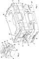
Ein Ausführungsbeispiel der Erfindung wird im Folgenden unter Bezugnahme auf die begleitenden Zeichnungen näher erläutert. Diese zeigen:
-
1 : Zwei gleichartige Systembehälter zu Beginn des Kopplungsvorgangs; -
2 : Ein Detail aus1 .
-
1 : Two similar system containers at the beginning of the coupling process; -
2 : A detail from1 ,
Die beiden Koppelungshaken
Wie den Figuren zu entnehmen ist, ist der Deckel
Zwischen den beiden Teilen
Die Verkoppelung zweier erfindungsgemäßer Systembehälter erfolgt wie nachfolgend dargestellt.The coupling of two inventive system container takes place as shown below.
Der in den
Nachdem der Systembehälter
Zum Lösen des Systembehälters
Die Erfindung bietet gegenüber den eingangs bekannten Systembehältern den Vorteil, dass eine intuitive Verkopplung möglich ist. Es ist nämlich nicht mehr notwendig, den oberen Systembehälter exakt vertikal auf den unteren Systembehälter aufzusetzen. Im Unterschied zu dem aus dem Stand der Technik bekannten Systembehälter sind nämlich die Führungsschächte
ZITATE ENTHALTEN IN DER BESCHREIBUNG QUOTES INCLUDE IN THE DESCRIPTION
Diese Liste der vom Anmelder aufgeführten Dokumente wurde automatisiert erzeugt und ist ausschließlich zur besseren Information des Lesers aufgenommen. Die Liste ist nicht Bestandteil der deutschen Patent- bzw. Gebrauchsmusteranmeldung. Das DPMA übernimmt keinerlei Haftung für etwaige Fehler oder Auslassungen.This list of the documents listed by the applicant has been generated automatically and is included solely for the better information of the reader. The list is not part of the German patent or utility model application. The DPMA assumes no liability for any errors or omissions.
Zitierte PatentliteraturCited patent literature
- DE 102013110496 [0002]DE 102013110496 [0002]
Claims (8)
Priority Applications (4)
| Application Number | Priority Date | Filing Date | Title |
|---|---|---|---|
| DE102017117823.6A DE102017117823A1 (en) | 2017-08-07 | 2017-08-07 | Stackable system tray |
| EP18164827.0A EP3441196B1 (en) | 2017-08-07 | 2018-03-29 | Stackable system container |
| CN201810530098.XA CN109383905B (en) | 2017-08-07 | 2018-05-29 | Stackable system container |
| US16/048,562 US10710770B2 (en) | 2017-08-07 | 2018-07-30 | Stackable container system |
Applications Claiming Priority (1)
| Application Number | Priority Date | Filing Date | Title |
|---|---|---|---|
| DE102017117823.6A DE102017117823A1 (en) | 2017-08-07 | 2017-08-07 | Stackable system tray |
Publications (1)
| Publication Number | Publication Date |
|---|---|
| DE102017117823A1 true DE102017117823A1 (en) | 2019-02-07 |
Family
ID=61837619
Family Applications (1)
| Application Number | Title | Priority Date | Filing Date |
|---|---|---|---|
| DE102017117823.6A Withdrawn DE102017117823A1 (en) | 2017-08-07 | 2017-08-07 | Stackable system tray |
Country Status (4)
| Country | Link |
|---|---|
| US (1) | US10710770B2 (en) |
| EP (1) | EP3441196B1 (en) |
| CN (1) | CN109383905B (en) |
| DE (1) | DE102017117823A1 (en) |
Families Citing this family (44)
| Publication number | Priority date | Publication date | Assignee | Title |
|---|---|---|---|---|
| US11267119B2 (en) | 2015-12-14 | 2022-03-08 | Milwaukee Electric Tool Corporation | Storage device system |
| CA2952711C (en) | 2015-12-22 | 2023-01-03 | Bombardier Recreational Products Inc. | Stackable container assembly |
| CA2987892C (en) | 2016-05-02 | 2021-04-20 | Keter Plastic Ltd. | Utility assembly and coupling mechanism |
| DE102016112853A1 (en) | 2016-07-13 | 2018-01-18 | Bs Systems Gmbh & Co. Kg | Stackable system tray |
| DE102016112855A1 (en) | 2016-07-13 | 2018-01-18 | Bs Systems Gmbh & Co. Kg | Stackable system tray |
| WO2018213560A1 (en) * | 2017-05-17 | 2018-11-22 | Milwaukee Electric Tool Corporation | Storage device system |
| WO2019028041A1 (en) | 2017-07-31 | 2019-02-07 | Milwaukee Electric Tool Corporation | STORAGE DEVICE SYSTEM |
| USD896517S1 (en) | 2017-08-09 | 2020-09-22 | Keter Plastic Ltd. | Tool box |
| DE102017128493B3 (en) | 2017-11-30 | 2018-08-16 | Bs Systems Gmbh & Co. Kg | Stackable system container and transport system |
| US11529985B2 (en) | 2017-12-20 | 2022-12-20 | Keter Plastic Ltd. | Trolley and mechanical braking system therefor |
| WO2019147801A2 (en) * | 2018-01-24 | 2019-08-01 | Milwaukee Electric Tool Corporation | Tool storage |
| IL257294A (en) | 2018-02-01 | 2018-03-29 | Milwaukee Electric Tool Corp | Coupleable crate |
| US10434638B1 (en) * | 2018-04-19 | 2019-10-08 | Chung-Yu Tsai | Tool box assembly |
| IL260225A (en) | 2018-06-24 | 2018-07-31 | Keter Plastic Ltd | Hand truck |
| US11486427B2 (en) * | 2018-07-18 | 2022-11-01 | The Stanley Works Israel Ltd. | Stacking latch mechanism |
| USD918580S1 (en) | 2018-08-07 | 2021-05-11 | Bs Systems Gmbh & Co. Kg | Transport case |
| CA3110535A1 (en) * | 2018-09-14 | 2020-03-19 | Tanos Gmbh Verpacken Ordnen Prasentieren | Storage device |
| USD898320S1 (en) | 2019-02-26 | 2020-10-06 | Keter Plastic Ltd. | Dolly |
| USD967693S1 (en) | 2019-02-26 | 2022-10-25 | Keter Plastic Ltd. | Mounting plate |
| IL265964A (en) | 2019-04-11 | 2019-07-31 | Milwaukee Electric Tool Corp | Racking system and coupler |
| US11364852B2 (en) * | 2019-04-17 | 2022-06-21 | Bombardier Recreational Products Inc. | Storage box assembly for a vehicle |
| USD919296S1 (en) | 2019-05-31 | 2021-05-18 | Keter Plastic Ltd. | Crate |
| USD917977S1 (en) | 2019-05-31 | 2021-05-04 | Keter Plastic Ltd. | Cooler |
| USD923935S1 (en) | 2019-05-31 | 2021-07-06 | Keter Plastic Ltd. | Toolbox |
| IL269564B2 (en) | 2019-09-23 | 2023-11-01 | Keter Home & Garden Products Ltd | Work donkey |
| DE102020104512B3 (en) | 2020-02-20 | 2021-01-07 | Bs Systems Gmbh & Co. Kg | Belt adapter and holding system comprising a belt adapter and a carrier element |
| USD913768S1 (en) * | 2020-03-18 | 2021-03-23 | Gabriel T. Villanueva | Stackable tool sorter |
| US12330446B2 (en) | 2020-04-30 | 2025-06-17 | Swimc Llc | Modular toolbox designed and organized for painting tools |
| EP4323154A4 (en) * | 2021-04-13 | 2025-03-26 | Milwaukee Electric Tool Corporation | COUPLING PLATFORM FOR UTILITY MODULE |
| US11788329B2 (en) | 2021-06-11 | 2023-10-17 | Ningbo E-Power Engine Technology Co., Ltd. | Latch structure |
| ES3032874T3 (en) * | 2021-07-09 | 2025-07-28 | Gt Line Srl | Set of transportable containers |
| EP4415930A1 (en) | 2021-10-15 | 2024-08-21 | Makita U.S.A., Inc. | Modular storage system with storage box connectivity and external box features |
| US12312126B2 (en) * | 2021-11-03 | 2025-05-27 | Meridian International Co., Ltd | Stacked toolbox system |
| US12161207B2 (en) * | 2022-01-26 | 2024-12-10 | Grown-Up Licenses Limited | Stack and lock system for storage product and storage container |
| US20230278191A1 (en) * | 2022-03-04 | 2023-09-07 | Meridian International Co., Ltd | Connection structure of module, storage box and storage box assembly |
| US20240286798A1 (en) | 2022-03-14 | 2024-08-29 | Home Depot Product Authority, Llc | Accessory attachment assembly for container |
| USD1024557S1 (en) | 2022-06-08 | 2024-04-30 | Yeti Coolers, Llc | Container |
| USD1063376S1 (en) | 2022-06-08 | 2025-02-25 | Yeti Coolers, Llc | Container |
| US11912477B2 (en) | 2022-06-08 | 2024-02-27 | Yeti Coolers, Llc | Container with handle and latching system |
| USD1036116S1 (en) | 2022-06-08 | 2024-07-23 | Yeti Coolers, Llc | Container |
| EP4302929B1 (en) * | 2022-07-04 | 2025-04-02 | Stanley Black & Decker MEA FZE | Container with a low profile latch |
| USD1059829S1 (en) | 2022-10-14 | 2025-02-04 | Makita U.S.A., Inc. | Storage box |
| USD1036119S1 (en) | 2022-11-30 | 2024-07-23 | Yeti Coolers, Llc | Container |
| USD1067755S1 (en) | 2023-03-14 | 2025-03-25 | Home Depot Product Authority, Llc | Attachable container accessory mount |
Citations (2)
| Publication number | Priority date | Publication date | Assignee | Title |
|---|---|---|---|---|
| DE102013110496A1 (en) | 2013-09-23 | 2015-03-26 | Bs Systems Gmbh & Co. Kg | Closure for a container |
| DE202015005752U1 (en) * | 2015-08-18 | 2016-11-21 | Plaston Ag | Stackable case with coupling connection and fuse |
Family Cites Families (8)
| Publication number | Priority date | Publication date | Assignee | Title |
|---|---|---|---|---|
| CN200995812Y (en) * | 2007-01-31 | 2007-12-26 | 黄金松 | Packing box |
| USRE47022E1 (en) * | 2009-12-11 | 2018-09-04 | The Stanley Works Israel Ltd. | Container |
| DE102011082155A1 (en) * | 2011-05-10 | 2012-11-15 | Robert Bosch Gmbh | system module |
| CN103781600B (en) * | 2011-09-06 | 2017-04-12 | 罗伯特·博世有限公司 | System module |
| DE202012102760U1 (en) * | 2012-07-23 | 2012-12-05 | Karl-Heinz Fuchs | transport device |
| TW201600265A (en) * | 2014-06-20 | 2016-01-01 | Es Jintzan Co Ltd | Toolbox unit |
| DE102016112855A1 (en) * | 2016-07-13 | 2018-01-18 | Bs Systems Gmbh & Co. Kg | Stackable system tray |
| DE102016112853A1 (en) * | 2016-07-13 | 2018-01-18 | Bs Systems Gmbh & Co. Kg | Stackable system tray |
-
2017
- 2017-08-07 DE DE102017117823.6A patent/DE102017117823A1/en not_active Withdrawn
-
2018
- 2018-03-29 EP EP18164827.0A patent/EP3441196B1/en active Active
- 2018-05-29 CN CN201810530098.XA patent/CN109383905B/en active Active
- 2018-07-30 US US16/048,562 patent/US10710770B2/en active Active
Patent Citations (2)
| Publication number | Priority date | Publication date | Assignee | Title |
|---|---|---|---|---|
| DE102013110496A1 (en) | 2013-09-23 | 2015-03-26 | Bs Systems Gmbh & Co. Kg | Closure for a container |
| DE202015005752U1 (en) * | 2015-08-18 | 2016-11-21 | Plaston Ag | Stackable case with coupling connection and fuse |
Also Published As
| Publication number | Publication date |
|---|---|
| CN109383905A (en) | 2019-02-26 |
| CN109383905B (en) | 2020-07-31 |
| EP3441196A1 (en) | 2019-02-13 |
| US10710770B2 (en) | 2020-07-14 |
| EP3441196B1 (en) | 2020-05-13 |
| US20190039781A1 (en) | 2019-02-07 |
Similar Documents
| Publication | Publication Date | Title |
|---|---|---|
| DE102017117823A1 (en) | Stackable system tray | |
| DE202014103695U1 (en) | Stackable container | |
| DE102009035201A1 (en) | Coupling device for coupling containers, in particular containers used in cargo ships | |
| DE102007052916A1 (en) | Anti-slip locking device for e.g. transport case, has long sides with center holes above and below locking device, and locking handle formed of bent recess, mounting plate surface and handle mounting part | |
| DE20108895U1 (en) | Box module for objects | |
| DE102012107955A1 (en) | container | |
| DE102017200906A1 (en) | Pressure cooker | |
| DE2751683B2 (en) | Plastic tabs or handles for attaching to the upper edge of sticky binders or hanging pockets | |
| DE202015106824U1 (en) | Pet crate | |
| EP0236380B1 (en) | Divisible crate for bottles | |
| DE202012101254U1 (en) | container | |
| EP3587294B1 (en) | Stackable container with connection mechanism | |
| DE202017104697U1 (en) | Stackable system tray | |
| DE3784093T2 (en) | FOLDER. | |
| DE202017107317U1 (en) | Stackable system container and transport system | |
| DE1452557A1 (en) | Device for the production of sealing capsules for hollow bodies | |
| DE1930482A1 (en) | Device for aligning and locking transport containers on vehicles | |
| DE102012017899A1 (en) | Holder i.e. clamp, for e.g. pipe, has upper and lower part detachably connected with one another by connection devices arranged at distance to middle plane, where each device has pin, locking recesses, bearing and engagement hook | |
| DE102014111337A1 (en) | Stackable container | |
| DE102015121865A1 (en) | Pet crate | |
| EP3997004B1 (en) | Container having a lockable cover | |
| DE202014010527U1 (en) | Lid for a container | |
| DE202010004726U1 (en) | Separating device for a sectional door | |
| EP2275281A2 (en) | Suspension device of suspended filing appliances | |
| DE2703432A1 (en) | Single blank folding cardboard box - has locking lug and recess in front panels with flexible noses hooking together (NL 8.8.77) |
Legal Events
| Date | Code | Title | Description |
|---|---|---|---|
| R012 | Request for examination validly filed | ||
| R120 | Application withdrawn or ip right abandoned |