DE102017108435A1 - Semiconductor laser diode and method for producing a semiconductor laser diode - Google Patents
Semiconductor laser diode and method for producing a semiconductor laser diode Download PDFInfo
- Publication number
- DE102017108435A1 DE102017108435A1 DE102017108435.5A DE102017108435A DE102017108435A1 DE 102017108435 A1 DE102017108435 A1 DE 102017108435A1 DE 102017108435 A DE102017108435 A DE 102017108435A DE 102017108435 A1 DE102017108435 A1 DE 102017108435A1
- Authority
- DE
- Germany
- Prior art keywords
- layer
- laser diode
- semiconductor laser
- semiconductor
- passivation layer
- Prior art date
- Legal status (The legal status is an assumption and is not a legal conclusion. Google has not performed a legal analysis and makes no representation as to the accuracy of the status listed.)
- Withdrawn
Links
- 239000004065 semiconductor Substances 0.000 title claims abstract description 225
- 238000004519 manufacturing process Methods 0.000 title claims abstract description 14
- 238000002161 passivation Methods 0.000 claims abstract description 155
- 238000000034 method Methods 0.000 claims abstract description 20
- GYHNNYVSQQEPJS-UHFFFAOYSA-N Gallium Chemical compound [Ga] GYHNNYVSQQEPJS-UHFFFAOYSA-N 0.000 claims abstract description 8
- 229910052733 gallium Inorganic materials 0.000 claims abstract description 8
- 239000000463 material Substances 0.000 claims description 81
- 229910002704 AlGaN Inorganic materials 0.000 claims description 30
- 150000001875 compounds Chemical class 0.000 claims description 17
- 239000000203 mixture Substances 0.000 claims description 16
- 238000000231 atomic layer deposition Methods 0.000 claims description 15
- 150000004767 nitrides Chemical class 0.000 claims description 8
- 230000008569 process Effects 0.000 claims description 7
- 239000013078 crystal Substances 0.000 claims 1
- 230000005855 radiation Effects 0.000 claims 1
- 239000010410 layer Substances 0.000 description 492
- 239000000758 substrate Substances 0.000 description 31
- 239000007858 starting material Substances 0.000 description 17
- 230000003287 optical effect Effects 0.000 description 15
- 238000006243 chemical reaction Methods 0.000 description 10
- 238000005253 cladding Methods 0.000 description 9
- 230000004888 barrier function Effects 0.000 description 8
- 230000008901 benefit Effects 0.000 description 7
- 238000000576 coating method Methods 0.000 description 7
- 239000002356 single layer Substances 0.000 description 7
- 230000015572 biosynthetic process Effects 0.000 description 6
- 239000011248 coating agent Substances 0.000 description 6
- 229910052717 sulfur Inorganic materials 0.000 description 6
- NINIDFKCEFEMDL-UHFFFAOYSA-N Sulfur Chemical compound [S] NINIDFKCEFEMDL-UHFFFAOYSA-N 0.000 description 5
- 230000017525 heat dissipation Effects 0.000 description 5
- 229910052751 metal Inorganic materials 0.000 description 5
- 239000002184 metal Substances 0.000 description 5
- 229910052760 oxygen Inorganic materials 0.000 description 5
- 239000011593 sulfur Substances 0.000 description 5
- 229910004298 SiO 2 Inorganic materials 0.000 description 4
- QVGXLLKOCUKJST-UHFFFAOYSA-N atomic oxygen Chemical compound [O] QVGXLLKOCUKJST-UHFFFAOYSA-N 0.000 description 4
- 230000007613 environmental effect Effects 0.000 description 4
- 239000001301 oxygen Substances 0.000 description 4
- 238000011161 development Methods 0.000 description 3
- 230000018109 developmental process Effects 0.000 description 3
- 238000009792 diffusion process Methods 0.000 description 3
- 230000005670 electromagnetic radiation Effects 0.000 description 3
- 239000007789 gas Substances 0.000 description 3
- 238000002156 mixing Methods 0.000 description 3
- 239000011241 protective layer Substances 0.000 description 3
- 238000000926 separation method Methods 0.000 description 3
- 230000003595 spectral effect Effects 0.000 description 3
- 230000007480 spreading Effects 0.000 description 3
- 238000003892 spreading Methods 0.000 description 3
- 230000007704 transition Effects 0.000 description 3
- XKRFYHLGVUSROY-UHFFFAOYSA-N Argon Chemical compound [Ar] XKRFYHLGVUSROY-UHFFFAOYSA-N 0.000 description 2
- IJGRMHOSHXDMSA-UHFFFAOYSA-N Atomic nitrogen Chemical compound N#N IJGRMHOSHXDMSA-UHFFFAOYSA-N 0.000 description 2
- CBENFWSGALASAD-UHFFFAOYSA-N Ozone Chemical compound [O-][O+]=O CBENFWSGALASAD-UHFFFAOYSA-N 0.000 description 2
- 238000002441 X-ray diffraction Methods 0.000 description 2
- 238000001816 cooling Methods 0.000 description 2
- 239000003989 dielectric material Substances 0.000 description 2
- 238000009826 distribution Methods 0.000 description 2
- 239000002019 doping agent Substances 0.000 description 2
- 238000005516 engineering process Methods 0.000 description 2
- 238000010438 heat treatment Methods 0.000 description 2
- 239000011261 inert gas Substances 0.000 description 2
- 150000002739 metals Chemical class 0.000 description 2
- 230000004048 modification Effects 0.000 description 2
- 238000012986 modification Methods 0.000 description 2
- 238000002360 preparation method Methods 0.000 description 2
- 230000009467 reduction Effects 0.000 description 2
- 229910002601 GaN Inorganic materials 0.000 description 1
- 229910005540 GaP Inorganic materials 0.000 description 1
- 229910001218 Gallium arsenide Inorganic materials 0.000 description 1
- 229910003363 ZnMgO Inorganic materials 0.000 description 1
- 229910007709 ZnTe Inorganic materials 0.000 description 1
- 238000010521 absorption reaction Methods 0.000 description 1
- 239000000956 alloy Substances 0.000 description 1
- 229910045601 alloy Inorganic materials 0.000 description 1
- 229910052782 aluminium Inorganic materials 0.000 description 1
- 229910052786 argon Inorganic materials 0.000 description 1
- 229910052790 beryllium Inorganic materials 0.000 description 1
- 230000000903 blocking effect Effects 0.000 description 1
- 229910052980 cadmium sulfide Inorganic materials 0.000 description 1
- 229910052791 calcium Inorganic materials 0.000 description 1
- 230000015556 catabolic process Effects 0.000 description 1
- 229910010293 ceramic material Inorganic materials 0.000 description 1
- 239000002800 charge carrier Substances 0.000 description 1
- 238000005229 chemical vapour deposition Methods 0.000 description 1
- 238000004140 cleaning Methods 0.000 description 1
- 239000004020 conductor Substances 0.000 description 1
- 230000008878 coupling Effects 0.000 description 1
- 238000010168 coupling process Methods 0.000 description 1
- 238000005859 coupling reaction Methods 0.000 description 1
- 230000007547 defect Effects 0.000 description 1
- 238000006731 degradation reaction Methods 0.000 description 1
- 230000001419 dependent effect Effects 0.000 description 1
- 238000000151 deposition Methods 0.000 description 1
- 230000008021 deposition Effects 0.000 description 1
- 230000000694 effects Effects 0.000 description 1
- 238000000407 epitaxy Methods 0.000 description 1
- 229910052737 gold Inorganic materials 0.000 description 1
- 230000005525 hole transport Effects 0.000 description 1
- 230000006872 improvement Effects 0.000 description 1
- 239000002346 layers by function Substances 0.000 description 1
- 239000003446 ligand Substances 0.000 description 1
- 229910052749 magnesium Inorganic materials 0.000 description 1
- 150000002736 metal compounds Chemical class 0.000 description 1
- 229910003465 moissanite Inorganic materials 0.000 description 1
- 238000001451 molecular beam epitaxy Methods 0.000 description 1
- 229910052757 nitrogen Inorganic materials 0.000 description 1
- 229910052763 palladium Inorganic materials 0.000 description 1
- 230000000149 penetrating effect Effects 0.000 description 1
- 230000035515 penetration Effects 0.000 description 1
- 229910052697 platinum Inorganic materials 0.000 description 1
- 229910052594 sapphire Inorganic materials 0.000 description 1
- 239000010980 sapphire Substances 0.000 description 1
- 239000003566 sealing material Substances 0.000 description 1
- 229910052711 selenium Inorganic materials 0.000 description 1
- SBIBMFFZSBJNJF-UHFFFAOYSA-N selenium;zinc Chemical compound [Se]=[Zn] SBIBMFFZSBJNJF-UHFFFAOYSA-N 0.000 description 1
- 229910010271 silicon carbide Inorganic materials 0.000 description 1
- 229910052709 silver Inorganic materials 0.000 description 1
- 238000004544 sputter deposition Methods 0.000 description 1
- 229910052712 strontium Inorganic materials 0.000 description 1
- 230000002123 temporal effect Effects 0.000 description 1
- 238000007740 vapor deposition Methods 0.000 description 1
- 238000000927 vapour-phase epitaxy Methods 0.000 description 1
- XLOMVQKBTHCTTD-UHFFFAOYSA-N zinc oxide Inorganic materials [Zn]=O XLOMVQKBTHCTTD-UHFFFAOYSA-N 0.000 description 1
Images


Classifications
-
- H—ELECTRICITY
- H01—ELECTRIC ELEMENTS
- H01S—DEVICES USING THE PROCESS OF LIGHT AMPLIFICATION BY STIMULATED EMISSION OF RADIATION [LASER] TO AMPLIFY OR GENERATE LIGHT; DEVICES USING STIMULATED EMISSION OF ELECTROMAGNETIC RADIATION IN WAVE RANGES OTHER THAN OPTICAL
- H01S5/00—Semiconductor lasers
- H01S5/20—Structure or shape of the semiconductor body to guide the optical wave ; Confining structures perpendicular to the optical axis, e.g. index or gain guiding, stripe geometry, broad area lasers, gain tailoring, transverse or lateral reflectors, special cladding structures, MQW barrier reflection layers
- H01S5/22—Structure or shape of the semiconductor body to guide the optical wave ; Confining structures perpendicular to the optical axis, e.g. index or gain guiding, stripe geometry, broad area lasers, gain tailoring, transverse or lateral reflectors, special cladding structures, MQW barrier reflection layers having a ridge or stripe structure
- H01S5/2205—Structure or shape of the semiconductor body to guide the optical wave ; Confining structures perpendicular to the optical axis, e.g. index or gain guiding, stripe geometry, broad area lasers, gain tailoring, transverse or lateral reflectors, special cladding structures, MQW barrier reflection layers having a ridge or stripe structure comprising special burying or current confinement layers
- H01S5/2206—Structure or shape of the semiconductor body to guide the optical wave ; Confining structures perpendicular to the optical axis, e.g. index or gain guiding, stripe geometry, broad area lasers, gain tailoring, transverse or lateral reflectors, special cladding structures, MQW barrier reflection layers having a ridge or stripe structure comprising special burying or current confinement layers based on III-V materials
- H01S5/221—Structure or shape of the semiconductor body to guide the optical wave ; Confining structures perpendicular to the optical axis, e.g. index or gain guiding, stripe geometry, broad area lasers, gain tailoring, transverse or lateral reflectors, special cladding structures, MQW barrier reflection layers having a ridge or stripe structure comprising special burying or current confinement layers based on III-V materials containing aluminium
-
- H—ELECTRICITY
- H01—ELECTRIC ELEMENTS
- H01S—DEVICES USING THE PROCESS OF LIGHT AMPLIFICATION BY STIMULATED EMISSION OF RADIATION [LASER] TO AMPLIFY OR GENERATE LIGHT; DEVICES USING STIMULATED EMISSION OF ELECTROMAGNETIC RADIATION IN WAVE RANGES OTHER THAN OPTICAL
- H01S5/00—Semiconductor lasers
- H01S5/02—Structural details or components not essential to laser action
- H01S5/028—Coatings ; Treatment of the laser facets, e.g. etching, passivation layers or reflecting layers
- H01S5/0287—Facet reflectivity
-
- H—ELECTRICITY
- H01—ELECTRIC ELEMENTS
- H01S—DEVICES USING THE PROCESS OF LIGHT AMPLIFICATION BY STIMULATED EMISSION OF RADIATION [LASER] TO AMPLIFY OR GENERATE LIGHT; DEVICES USING STIMULATED EMISSION OF ELECTROMAGNETIC RADIATION IN WAVE RANGES OTHER THAN OPTICAL
- H01S5/00—Semiconductor lasers
- H01S5/20—Structure or shape of the semiconductor body to guide the optical wave ; Confining structures perpendicular to the optical axis, e.g. index or gain guiding, stripe geometry, broad area lasers, gain tailoring, transverse or lateral reflectors, special cladding structures, MQW barrier reflection layers
- H01S5/22—Structure or shape of the semiconductor body to guide the optical wave ; Confining structures perpendicular to the optical axis, e.g. index or gain guiding, stripe geometry, broad area lasers, gain tailoring, transverse or lateral reflectors, special cladding structures, MQW barrier reflection layers having a ridge or stripe structure
- H01S5/2205—Structure or shape of the semiconductor body to guide the optical wave ; Confining structures perpendicular to the optical axis, e.g. index or gain guiding, stripe geometry, broad area lasers, gain tailoring, transverse or lateral reflectors, special cladding structures, MQW barrier reflection layers having a ridge or stripe structure comprising special burying or current confinement layers
- H01S5/2206—Structure or shape of the semiconductor body to guide the optical wave ; Confining structures perpendicular to the optical axis, e.g. index or gain guiding, stripe geometry, broad area lasers, gain tailoring, transverse or lateral reflectors, special cladding structures, MQW barrier reflection layers having a ridge or stripe structure comprising special burying or current confinement layers based on III-V materials
-
- H—ELECTRICITY
- H01—ELECTRIC ELEMENTS
- H01S—DEVICES USING THE PROCESS OF LIGHT AMPLIFICATION BY STIMULATED EMISSION OF RADIATION [LASER] TO AMPLIFY OR GENERATE LIGHT; DEVICES USING STIMULATED EMISSION OF ELECTROMAGNETIC RADIATION IN WAVE RANGES OTHER THAN OPTICAL
- H01S5/00—Semiconductor lasers
- H01S5/20—Structure or shape of the semiconductor body to guide the optical wave ; Confining structures perpendicular to the optical axis, e.g. index or gain guiding, stripe geometry, broad area lasers, gain tailoring, transverse or lateral reflectors, special cladding structures, MQW barrier reflection layers
- H01S5/22—Structure or shape of the semiconductor body to guide the optical wave ; Confining structures perpendicular to the optical axis, e.g. index or gain guiding, stripe geometry, broad area lasers, gain tailoring, transverse or lateral reflectors, special cladding structures, MQW barrier reflection layers having a ridge or stripe structure
- H01S5/2205—Structure or shape of the semiconductor body to guide the optical wave ; Confining structures perpendicular to the optical axis, e.g. index or gain guiding, stripe geometry, broad area lasers, gain tailoring, transverse or lateral reflectors, special cladding structures, MQW barrier reflection layers having a ridge or stripe structure comprising special burying or current confinement layers
- H01S5/2218—Structure or shape of the semiconductor body to guide the optical wave ; Confining structures perpendicular to the optical axis, e.g. index or gain guiding, stripe geometry, broad area lasers, gain tailoring, transverse or lateral reflectors, special cladding structures, MQW barrier reflection layers having a ridge or stripe structure comprising special burying or current confinement layers having special optical properties
- H01S5/222—Structure or shape of the semiconductor body to guide the optical wave ; Confining structures perpendicular to the optical axis, e.g. index or gain guiding, stripe geometry, broad area lasers, gain tailoring, transverse or lateral reflectors, special cladding structures, MQW barrier reflection layers having a ridge or stripe structure comprising special burying or current confinement layers having special optical properties having a refractive index lower than that of the cladding layers or outer guiding layers
-
- H—ELECTRICITY
- H01—ELECTRIC ELEMENTS
- H01S—DEVICES USING THE PROCESS OF LIGHT AMPLIFICATION BY STIMULATED EMISSION OF RADIATION [LASER] TO AMPLIFY OR GENERATE LIGHT; DEVICES USING STIMULATED EMISSION OF ELECTROMAGNETIC RADIATION IN WAVE RANGES OTHER THAN OPTICAL
- H01S5/00—Semiconductor lasers
- H01S5/20—Structure or shape of the semiconductor body to guide the optical wave ; Confining structures perpendicular to the optical axis, e.g. index or gain guiding, stripe geometry, broad area lasers, gain tailoring, transverse or lateral reflectors, special cladding structures, MQW barrier reflection layers
- H01S5/22—Structure or shape of the semiconductor body to guide the optical wave ; Confining structures perpendicular to the optical axis, e.g. index or gain guiding, stripe geometry, broad area lasers, gain tailoring, transverse or lateral reflectors, special cladding structures, MQW barrier reflection layers having a ridge or stripe structure
- H01S5/2205—Structure or shape of the semiconductor body to guide the optical wave ; Confining structures perpendicular to the optical axis, e.g. index or gain guiding, stripe geometry, broad area lasers, gain tailoring, transverse or lateral reflectors, special cladding structures, MQW barrier reflection layers having a ridge or stripe structure comprising special burying or current confinement layers
- H01S5/2222—Structure or shape of the semiconductor body to guide the optical wave ; Confining structures perpendicular to the optical axis, e.g. index or gain guiding, stripe geometry, broad area lasers, gain tailoring, transverse or lateral reflectors, special cladding structures, MQW barrier reflection layers having a ridge or stripe structure comprising special burying or current confinement layers having special electric properties
- H01S5/2227—Structure or shape of the semiconductor body to guide the optical wave ; Confining structures perpendicular to the optical axis, e.g. index or gain guiding, stripe geometry, broad area lasers, gain tailoring, transverse or lateral reflectors, special cladding structures, MQW barrier reflection layers having a ridge or stripe structure comprising special burying or current confinement layers having special electric properties special thin layer sequence
-
- H—ELECTRICITY
- H01—ELECTRIC ELEMENTS
- H01S—DEVICES USING THE PROCESS OF LIGHT AMPLIFICATION BY STIMULATED EMISSION OF RADIATION [LASER] TO AMPLIFY OR GENERATE LIGHT; DEVICES USING STIMULATED EMISSION OF ELECTROMAGNETIC RADIATION IN WAVE RANGES OTHER THAN OPTICAL
- H01S5/00—Semiconductor lasers
- H01S5/20—Structure or shape of the semiconductor body to guide the optical wave ; Confining structures perpendicular to the optical axis, e.g. index or gain guiding, stripe geometry, broad area lasers, gain tailoring, transverse or lateral reflectors, special cladding structures, MQW barrier reflection layers
- H01S5/22—Structure or shape of the semiconductor body to guide the optical wave ; Confining structures perpendicular to the optical axis, e.g. index or gain guiding, stripe geometry, broad area lasers, gain tailoring, transverse or lateral reflectors, special cladding structures, MQW barrier reflection layers having a ridge or stripe structure
- H01S5/223—Buried stripe structure
- H01S5/2231—Buried stripe structure with inner confining structure only between the active layer and the upper electrode
-
- H—ELECTRICITY
- H01—ELECTRIC ELEMENTS
- H01S—DEVICES USING THE PROCESS OF LIGHT AMPLIFICATION BY STIMULATED EMISSION OF RADIATION [LASER] TO AMPLIFY OR GENERATE LIGHT; DEVICES USING STIMULATED EMISSION OF ELECTROMAGNETIC RADIATION IN WAVE RANGES OTHER THAN OPTICAL
- H01S5/00—Semiconductor lasers
- H01S5/30—Structure or shape of the active region; Materials used for the active region
- H01S5/34—Structure or shape of the active region; Materials used for the active region comprising quantum well or superlattice structures, e.g. single quantum well [SQW] lasers, multiple quantum well [MQW] lasers or graded index separate confinement heterostructure [GRINSCH] lasers
- H01S5/343—Structure or shape of the active region; Materials used for the active region comprising quantum well or superlattice structures, e.g. single quantum well [SQW] lasers, multiple quantum well [MQW] lasers or graded index separate confinement heterostructure [GRINSCH] lasers in AIIIBV compounds, e.g. AlGaAs-laser, InP-based laser
- H01S5/34333—Structure or shape of the active region; Materials used for the active region comprising quantum well or superlattice structures, e.g. single quantum well [SQW] lasers, multiple quantum well [MQW] lasers or graded index separate confinement heterostructure [GRINSCH] lasers in AIIIBV compounds, e.g. AlGaAs-laser, InP-based laser with a well layer based on Ga(In)N or Ga(In)P, e.g. blue laser
-
- H—ELECTRICITY
- H01—ELECTRIC ELEMENTS
- H01S—DEVICES USING THE PROCESS OF LIGHT AMPLIFICATION BY STIMULATED EMISSION OF RADIATION [LASER] TO AMPLIFY OR GENERATE LIGHT; DEVICES USING STIMULATED EMISSION OF ELECTROMAGNETIC RADIATION IN WAVE RANGES OTHER THAN OPTICAL
- H01S2301/00—Functional characteristics
- H01S2301/17—Semiconductor lasers comprising special layers
- H01S2301/176—Specific passivation layers on surfaces other than the emission facet
-
- H—ELECTRICITY
- H01—ELECTRIC ELEMENTS
- H01S—DEVICES USING THE PROCESS OF LIGHT AMPLIFICATION BY STIMULATED EMISSION OF RADIATION [LASER] TO AMPLIFY OR GENERATE LIGHT; DEVICES USING STIMULATED EMISSION OF ELECTROMAGNETIC RADIATION IN WAVE RANGES OTHER THAN OPTICAL
- H01S5/00—Semiconductor lasers
- H01S5/02—Structural details or components not essential to laser action
- H01S5/022—Mountings; Housings
- H01S5/0233—Mounting configuration of laser chips
- H01S5/0234—Up-side down mountings, e.g. Flip-chip, epi-side down mountings or junction down mountings
-
- H—ELECTRICITY
- H01—ELECTRIC ELEMENTS
- H01S—DEVICES USING THE PROCESS OF LIGHT AMPLIFICATION BY STIMULATED EMISSION OF RADIATION [LASER] TO AMPLIFY OR GENERATE LIGHT; DEVICES USING STIMULATED EMISSION OF ELECTROMAGNETIC RADIATION IN WAVE RANGES OTHER THAN OPTICAL
- H01S5/00—Semiconductor lasers
- H01S5/10—Construction or shape of the optical resonator, e.g. extended or external cavity, coupled cavities, bent-guide, varying width, thickness or composition of the active region
- H01S5/16—Window-type lasers, i.e. with a region of non-absorbing material between the active region and the reflecting surface
- H01S5/168—Window-type lasers, i.e. with a region of non-absorbing material between the active region and the reflecting surface with window regions comprising current blocking layers
-
- H—ELECTRICITY
- H01—ELECTRIC ELEMENTS
- H01S—DEVICES USING THE PROCESS OF LIGHT AMPLIFICATION BY STIMULATED EMISSION OF RADIATION [LASER] TO AMPLIFY OR GENERATE LIGHT; DEVICES USING STIMULATED EMISSION OF ELECTROMAGNETIC RADIATION IN WAVE RANGES OTHER THAN OPTICAL
- H01S5/00—Semiconductor lasers
- H01S5/20—Structure or shape of the semiconductor body to guide the optical wave ; Confining structures perpendicular to the optical axis, e.g. index or gain guiding, stripe geometry, broad area lasers, gain tailoring, transverse or lateral reflectors, special cladding structures, MQW barrier reflection layers
- H01S5/22—Structure or shape of the semiconductor body to guide the optical wave ; Confining structures perpendicular to the optical axis, e.g. index or gain guiding, stripe geometry, broad area lasers, gain tailoring, transverse or lateral reflectors, special cladding structures, MQW barrier reflection layers having a ridge or stripe structure
- H01S5/2205—Structure or shape of the semiconductor body to guide the optical wave ; Confining structures perpendicular to the optical axis, e.g. index or gain guiding, stripe geometry, broad area lasers, gain tailoring, transverse or lateral reflectors, special cladding structures, MQW barrier reflection layers having a ridge or stripe structure comprising special burying or current confinement layers
- H01S5/2222—Structure or shape of the semiconductor body to guide the optical wave ; Confining structures perpendicular to the optical axis, e.g. index or gain guiding, stripe geometry, broad area lasers, gain tailoring, transverse or lateral reflectors, special cladding structures, MQW barrier reflection layers having a ridge or stripe structure comprising special burying or current confinement layers having special electric properties
Landscapes
- Physics & Mathematics (AREA)
- Condensed Matter Physics & Semiconductors (AREA)
- General Physics & Mathematics (AREA)
- Electromagnetism (AREA)
- Optics & Photonics (AREA)
- Geometry (AREA)
- Semiconductor Lasers (AREA)
Abstract
Es wird eine Halbleiterlaserdiode (100) angegeben, die eine durch ein Epitaxieverfahren hergestellte Halbleiterschichtenfolge (2) mit zumindest einer aktiven Schicht (3) aufweist, wobei auf zumindest einem Oberflächenbereich (20) der Halbleiterschichtenfolge (2) eine Gallium-haltige Passivierungsschicht (10) angeordnet ist.Weiterhin wird ein Verfahren zur Herstellung einer Halbleiterlaserdiode (100) angegeben.The invention relates to a semiconductor laser diode (100) which has a semiconductor layer sequence (2) with at least one active layer (3) produced by an epitaxial method, wherein a gallium-containing passivation layer (10) is formed on at least one surface region (20) of the semiconductor layer sequence (2). Further, a method of manufacturing a semiconductor laser diode (100) is given.
Description
Es werden eine Halbleiterlaserdiode und ein Verfahren zur Herstellung einer Halbleiterlaserdiode angegeben.A semiconductor laser diode and a method of manufacturing a semiconductor laser diode are disclosed.
Laserdioden im spektralen Bereich von Ultraviolett bis Infrarot erschließen in zunehmendem Maße neue Märkte, beispielsweise im Bereich von Beleuchtungs-, Projektions- und Materialbearbeitungsanwendungen, bei denen sie ihre Vorteile hinsichtlich erhöhter Leuchtdichte, insbesondere auch gegenüber Licht emittierenden Dioden (LEDs), ausspielen können. Derartige Laserdioden basieren im Wesentlichen auf Epitaxie-Strukturen im InAlGaN-, InAlGaP- oder InAlGaAs-Materialsystem. Bei der chiptechnologischen Herstellung werden standardmäßig zur Strombegrenzung wie auch zur Indexführung dielektrische Passivierungsmaterialien, beispielsweise aus SiO2, Si3N4 oder ZrO2, eingesetzt. Problematisch kann dabei aber sein, dass der Brechungsindex der Passivierung abhängig vom jeweils verwendeten Dielektrikum nur in äußerst engen Grenzen variiert werden kann. Zudem weisen diese dielektrischen Materialien eine geringe Wärmeleitfähigkeit auf und sind hinsichtlich ihrer Überformungseigenschaften und ihrer Abschirmwirkung für viele Anwendungen und Leistungsbereiche nur unzureichend geeignet. Diese Nachteile können einerseits zu Effizienzeinbußen und andererseits zu Bauteilstabilitätsproblemen führen.Laser diodes in the spectral range from ultraviolet to infrared are increasingly opening up new markets, for example in the field of lighting, projection and material processing applications, where they can exploit their advantages in terms of increased luminance, in particular also with respect to light emitting diodes (LEDs). Such laser diodes are based essentially on epitaxial structures in the InAlGaN, InAlGaP or InAlGaAs material system. In the production of chip technology, dielectric passivation materials, for example of SiO 2 , Si 3 N 4 or ZrO 2 , are used by default for current limitation as well as for index guidance. However, the problem may be that the refractive index of the passivation can only be varied within extremely narrow limits, depending on the particular dielectric used. In addition, these dielectric materials have a low thermal conductivity and are inadequate in many applications and performance ranges in terms of their overdosage properties and their shielding effect. On the one hand, these disadvantages can lead to efficiency losses and, on the other hand, to component stability problems.
Zumindest eine Aufgabe von bestimmten Ausführungsformen ist es, eine Halbleiterlaserdiode anzugeben. Zumindest eine weitere Aufgabe von bestimmten Ausführungsformen ist es, ein Verfahren zur Herstellung einer Halbleiterlaserdiode anzugeben.At least one object of certain embodiments is to provide a semiconductor laser diode. At least another object of certain embodiments is to provide a method of manufacturing a semiconductor laser diode.
Diese Aufgaben werden durch einen Gegenstand und ein Verfahren gemäß der unabhängigen Patentansprüche gelöst. Vorteilhafte Ausführungsformen und Weiterbildungen des Gegenstands und des Verfahrens sind in den abhängigen Ansprüchen gekennzeichnet und gehen weiterhin aus der nachfolgenden Beschreibung und den Zeichnungen hervor.These objects are achieved by an article and a method according to the independent claims. Advantageous embodiments and further developments of the subject matter and of the method are characterized in the dependent claims and furthermore emerge from the following description and the drawings.
Gemäß zumindest einer Ausführungsform weist eine Halbleiterlaserdiode zumindest eine aktive Schicht auf, die dazu eingerichtet und vorgesehen ist, im Betrieb in einem aktiven Bereich Licht zu erzeugen. Die aktive Schicht kann insbesondere Teil einer Halbleiterschichtenfolge mit einer Mehrzahl von Halbleiterschichten sein und eine Haupterstreckungsebene aufweisen, die senkrecht zu einer Anordnungsrichtung der Schichten der Halbleiterschichtenfolge ist. Beispielsweise kann die aktive Schicht genau einen aktiven Bereich aufweisen. Der aktive Bereich kann zumindest teilweise durch eine Kontaktfläche der Halbleiterschichtenfolge mit einer Elektrodenschicht definiert sein, also zumindest teilweise durch eine Fläche, über die eine Stromeinprägung in die Halbleiterschichtenfolge und damit in die aktive Schicht erfolgt. Weiterhin kann der aktive Bereich zumindest teilweise auch durch eine Stegwellenleiterstruktur definiert sein, also durch einen im Halbleitermaterial der Halbleiterschichtenfolge in Form einer länglichen Erhöhung gebildeten Steg. Darüber hinaus kann die aktive Schicht auch eine Mehrzahl von aktiven Bereichen aufweisen, die durch eine entsprechende Mehrzahl der beschriebenen Maßnahmen definiert sein können. Auch wenn sich die im Folgenden beschriebenen Merkmale und Ausführungsformen zumeist auf eine Halbleiterlaserdiode mit einem aktiven Bereich in der aktiven Schicht und damit gegebenenfalls entsprechend mit einer Stegwellenleiterstruktur beziehen, gelten die nachfolgenden Ausführungen in entsprechender Weise auch für Halbleiterlaserdiode mit einer Mehrzahl von aktiven Bereichen in der aktiven Schicht und damit gegebenenfalls entsprechend mit einer Mehrzahl von Stegwellenleiterstrukturen.In accordance with at least one embodiment, a semiconductor laser diode has at least one active layer, which is set up and provided to generate light in an active region during operation. In particular, the active layer may be part of a semiconductor layer sequence with a plurality of semiconductor layers and may have a main extension plane that is perpendicular to an arrangement direction of the layers of the semiconductor layer sequence. For example, the active layer may have exactly one active region. The active region can be defined at least partially by a contact surface of the semiconductor layer sequence with an electrode layer, that is to say at least partially through a surface via which current is injected into the semiconductor layer sequence and thus into the active layer. Furthermore, the active region can also be at least partially defined by a ridge waveguide structure, that is, by a ridge formed in the semiconductor material of the semiconductor layer sequence in the form of an elongate ridge. In addition, the active layer may also include a plurality of active regions that may be defined by a corresponding plurality of the described measures. Although the features and embodiments described below generally relate to a semiconductor laser diode having an active region in the active layer and thus possibly corresponding to a ridge waveguide structure, the following statements also apply correspondingly to semiconductor laser diodes having a plurality of active regions in the active region Layer and thus optionally with a corresponding plurality of ridge waveguide structures.
Gemäß einer weiteren Ausführungsform wird bei einem Verfahren zur Herstellung einer Halbleiterlaserdiode eine aktive Schicht hergestellt, die dazu eingerichtet und vorgesehen ist, im Betrieb der Halbleiterlaserdiode Licht zu erzeugen. Insbesondere kann eine Halbleiterschichtenfolge mit der aktiven Schicht mittels eines Epitaxieverfahrens hergestellt werden. Die vorab und im Folgenden beschriebenen Ausführungsbeispiele und Merkmale gelten gleichermaßen für die Halbleiterlaserdiode wie auch für das Verfahren zur Herstellung der Halbleiterlaserdiode.According to a further embodiment, in a method for producing a semiconductor laser diode, an active layer is produced, which is set up and provided to generate light during operation of the semiconductor laser diode. In particular, a semiconductor layer sequence with the active layer can be produced by means of an epitaxial process. The embodiments and features described above and below apply equally to the semiconductor laser diode as well as to the method for producing the semiconductor laser diode.
Gemäß einer weiteren Ausführungsform weist die Halbleiterlaserdiode eine Lichtauskoppelfläche und eine der Lichtauskoppelfläche gegenüberliegende Rückseitenfläche auf. Die Lichtauskoppelfläche und die Rückseitenfläche können insbesondere Seitenflächen der Halbleiterlaserdiode, besonders bevorzugt Seitenflächen der Halbleiterschichtenfolge, sein, die auch als sogenannte Facetten bezeichnet werden können. Über die Lichtauskoppelfläche kann die Halbleiterlaserdiode im Betrieb das im aktiven Bereich erzeugte Licht abstrahlen. Auf der Lichtauskoppelfläche und der Rückseitenfläche können geeignete optische Beschichtungen, insbesondere reflektierende oder teilreflektierende Schichten oder Schichtenfolgen, aufgebracht sein, die einen optischen Resonator für das in der aktiven Schicht erzeugte Licht bilden können. Der aktive Bereich kann sich zwischen der Rückseitenfläche und der Lichtauskoppelfläche entlang einer Richtung erstrecken, die hier und im Folgenden als longitudinale Richtung bezeichnet wird. Die longitudinale Richtung kann insbesondere parallel zur Haupterstreckungsebene der aktiven Schicht sein. Die Anordnungsrichtung der Schichten übereinander, also eine Richtung senkrecht zur Haupterstreckungsebene der aktiven Schicht, wird hier und im Folgenden als vertikale Richtung bezeichnet. Eine Richtung senkrecht zur longitudinalen Richtung und senkrecht zur vertikalen Richtung wird hier und im Folgenden als laterale Richtung bezeichnet. Die longitudinale Richtung und die laterale Richtung können somit eine Ebene aufspannen, die parallel zur Haupterstreckungsebene der aktiven Schicht ist.According to a further embodiment, the semiconductor laser diode has a light outcoupling surface and a rear side surface lying opposite the light outcoupling surface. The light outcoupling surface and the rear side surface may in particular be side surfaces of the semiconductor laser diode, particularly preferably side surfaces of the semiconductor layer sequence, which may also be referred to as so-called facets. During operation, the semiconductor laser diode can emit the light generated in the active region via the light output surface. Suitable optical coatings, in particular reflective or partially reflecting layers or layer sequences, which can form an optical resonator for the light generated in the active layer, can be applied to the light output surface and the rear side surface. The active region may extend between the back surface and the light outcoupling surface along a direction, which is referred to herein and hereinafter as a longitudinal direction. The longitudinal direction may, in particular, be parallel to the main extension plane of the active layer. The arrangement direction of the layers one above the other, so one Direction perpendicular to the main plane of extension of the active layer is referred to here and below as the vertical direction. A direction perpendicular to the longitudinal direction and perpendicular to the vertical direction is referred to here and below as a lateral direction. The longitudinal direction and the lateral direction can thus span a plane which is parallel to the main extension plane of the active layer.
Die Halbleiterschichtenfolge kann insbesondere als Epitaxieschichtenfolge, also als epitaktisch gewachsene Halbleiterschichtenfolge, ausgeführt sein. Dabei kann die Halbleiterschichtenfolge beispielsweise auf der Basis von InAlGaN ausgeführt sein. Unter InAlGaN-basierte Halbleiterschichtenfolgen fallen insbesondere solche, bei denen die epitaktisch hergestellte Halbleiterschichtenfolge in der Regel eine Schichtenfolge aus unterschiedlichen Einzelschichten aufweist, die mindestens eine Einzelschicht enthält, die ein Material aus dem III-V-Verbindungshalbleitermaterialsystem InxAlyGa1-x-yN mit 0 ≤ x ≤ 1, 0 ≤ y ≤ 1 und x + y ≤ 1 aufweist. Insbesondere kann die aktive Schicht auf einem solchen Material basieren. Halbleiterschichtenfolgen, die zumindest eine aktive Schicht auf Basis auf InAlGaN aufweisen, können beispielsweise bevorzugt elektromagnetische Strahlung in einem ultravioletten bis grünen Wellenlängenbereich emittieren.The semiconductor layer sequence may in particular be embodied as an epitaxial layer sequence, that is to say as an epitaxially grown semiconductor layer sequence. In this case, the semiconductor layer sequence can be embodied, for example, on the basis of InAlGaN. InAlGaN-based semiconductor layer sequences include, in particular, those in which the epitaxially produced semiconductor layer sequence generally has a layer sequence of different individual layers which contains at least one single layer comprising a material of the III-V compound semiconductor material system In x Al y Ga 1-xy N with 0 ≤ x ≤ 1, 0 ≤ y ≤ 1 and x + y ≤ 1. In particular, the active layer may be based on such a material. Semiconductor layer sequences which comprise at least one active layer based on InAlGaN, for example, can preferably emit electromagnetic radiation in an ultraviolet to green wavelength range.
Alternativ oder zusätzlich kann die Halbleiterschichtenfolge auch auf InAlGaP basieren, das heißt, dass die Halbleiterschichtenfolge unterschiedliche Einzelschichten aufweisen kann, wovon mindestens eine Einzelschicht, beispielsweise die aktive Schicht, ein Material aus dem III-V-Verbindungshalbleitermaterialsystem InxAlyGa1-x-yP mit 0 ≤ x ≤ 1, 0 ≤ y ≤ 1 und x + y ≤ 1 aufweist. Halbleiterschichtenfolgen, die zumindest eine aktive Schicht auf Basis von InAlGaP aufweisen, können beispielsweise bevorzugt elektromagnetische Strahlung mit einer oder mehreren spektralen Komponenten in einem grünen bis roten Wellenlängenbereich emittieren.Alternatively or additionally, the semiconductor layer sequence can also be based on InAlGaP, that is to say that the semiconductor layer sequence can have different individual layers, of which at least one individual layer, for example the active layer, is a material composed of the III-V compound semiconductor material system In x Al y Ga 1-xy P with 0 ≤ x ≤ 1, 0 ≤ y ≤ 1 and x + y ≤ 1. For example, semiconductor layer sequences comprising at least one InAlGaP-based active layer may preferentially emit electromagnetic radiation having one or more spectral components in a green to red wavelength range.
Alternativ oder zusätzlich kann die Halbleiterschichtenfolge auch andere III-V-Verbindungshalbleitermaterialsysteme, beispielsweise ein InAlGaAs-basiertes Material, oder II-VI-Verbindungshalbleitermaterialsysteme aufweisen. Insbesondere kann eine aktive Schicht, die ein InAlGaAs-basiertes Material aufweist, geeignet sein, elektromagnetische Strahlung mit einer oder mehreren spektralen Komponenten in einem roten bis infraroten Wellenlängenbereich zu emittieren. Ein II-VI-Verbindungshalbleitermaterial kann wenigstens ein Element aus der zweiten Hauptgruppe, wie beispielsweise Be, Mg, Ca, Sr, und ein Element aus der sechsten Hauptgruppe, wie beispielsweise O, S, Se, aufweisen. Beispielsweise gehören zu den II-VI-Verbindungshalbleitermaterialien ZnSe, ZnTe, ZnO, ZnMgO, CdS, ZnCdS und MgBeO.Alternatively or additionally, the semiconductor layer sequence can also comprise other III-V compound semiconductor material systems, for example an InAlGaAs-based material, or II-VI compound semiconductor material systems. In particular, an active layer comprising an InAlGaAs-based material may be capable of emitting electromagnetic radiation having one or more spectral components in a red to infrared wavelength range. An II-VI compound semiconductor material may have at least one second main group element such as Be, Mg, Ca, Sr, and a sixth main group element such as O, S, Se. For example, the II-VI compound semiconductor materials include ZnSe, ZnTe, ZnO, ZnMgO, CdS, ZnCdS and MgBeO.
Die aktive Schicht und insbesondere die Halbleiterschichtenfolge mit der aktiven Schicht können auf einem Substrat aufgebracht sein. Beispielsweise kann das Substrat als Aufwachssubstrat ausgebildet sein, auf dem die Halbleiterschichtenfolge aufgewachsen wird. Die aktive Schicht und insbesondere die Halbleiterschichtenfolge mit der aktiven Schicht können mittels eines Epitaxieverfahrens, beispielsweise mittels metallorganischer Gasphasenepitaxie (MOVPE) oder Molekularstrahlepitaxie (MBE), hergestellt werden. Das kann insbesondere bedeuten, dass die Halbleiterschichtenfolge auf dem Aufwachssubstrat aufgewachsen wird. Weiterhin kann die Halbleiterschichtenfolge mit elektrischen Kontakten in Form von Elektrodenschichten versehen werden. Darüber hinaus kann es auch möglich sein, dass das Aufwachssubstrat nach dem Aufwachsprozess entfernt wird. Hierbei kann die Halbleiterschichtenfolge beispielsweise auch nach dem Aufwachsen auf ein als Trägersubstrat ausgebildetes Substrat übertragen werden. Das Substrat kann ein Halbleitermaterial, beispielsweise ein oben genanntes Verbindungshalbleitermaterialsystem, oder ein anderes Material umfassen. Insbesondere kann das Substrat Saphir, GaAs, GaP, GaN, InP, SiC, Si, Ge und/oder ein Keramikmaterial wie beispielsweise SiN oder AlN umfassen oder aus einem solchen Material sein.The active layer and in particular the semiconductor layer sequence with the active layer can be applied to a substrate. For example, the substrate may be formed as a growth substrate, on which the semiconductor layer sequence is grown. The active layer and in particular the semiconductor layer sequence with the active layer can be produced by means of an epitaxy process, for example by means of metalorganic vapor phase epitaxy (MOVPE) or molecular beam epitaxy (MBE). This may mean, in particular, that the semiconductor layer sequence is grown on the growth substrate. Furthermore, the semiconductor layer sequence can be provided with electrical contacts in the form of electrode layers. In addition, it may also be possible for the growth substrate to be removed after the growth process. In this case, for example, the semiconductor layer sequence can also be transferred after being grown to a substrate designed as a carrier substrate. The substrate may comprise a semiconductor material, for example an above-mentioned compound semiconductor material system, or another material. In particular, the substrate may include or be made of sapphire, GaAs, GaP, GaN, InP, SiC, Si, Ge and / or a ceramic material such as SiN or AlN.
Die aktive Schicht kann beispielsweise einen herkömmlichen pn-Übergang, eine Doppelheterostruktur, eine Einfach-Quantentopfstruktur (SQW-Struktur) oder eine Mehrfach-Quantentopfstruktur (MQW-Struktur) zur Lichterzeugung aufweisen. Die Halbleiterschichtenfolge kann zusätzlich zur aktiven Schicht weitere funktionale Schichten und funktionelle Bereiche umfassen, etwa p- oder n-dotierte Ladungsträgertransportschichten, also Elektronen- oder Löchertransportschichten, undotierte oder p- oder n-dotierte Confinement-, Cladding- oder Wellenleiterschichten, Barriereschichten, Planarisierungsschichten, Pufferschichten, Schutzschichten und/oder Elektrodenschichten sowie Kombinationen daraus. Darüber hinaus können zusätzliche Schichten, etwa Pufferschichten, Barriereschichten und/oder Schutzschichten, auch senkrecht zur Aufwachsrichtung der Halbleiterschichtenfolge beispielsweise um die Halbleiterschichtenfolge herum angeordnet sein, also etwa auf den Seitenflächen der Halbleiterschichtenfolge.The active layer may comprise, for example, a conventional pn junction, a double heterostructure, a single quantum well structure (SQW structure) or a multiple quantum well structure (MQW structure) for light generation. The semiconductor layer sequence may comprise, in addition to the active layer, further functional layers and functional regions, such as p- or n-doped charge carrier transport layers, ie electron or hole transport layers, undoped or p- or n-doped confinement, cladding or waveguide layers, barrier layers, planarization layers, Buffer layers, protective layers and / or electrode layers and combinations thereof. In addition, additional layers, for example buffer layers, barrier layers and / or protective layers, can also be arranged perpendicular to the growth direction of the semiconductor layer sequence, for example around the semiconductor layer sequence, ie approximately on the side surfaces of the semiconductor layer sequence.
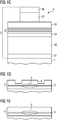
Gemäß einer weiteren Ausführungsform weist die Halbleiterschichtenfolge zumindest eine Stegwellenleiterstruktur auf. Weist die Halbleiterlaserdiode ein Substrat auf, auf dem die Halbleiterschichtenfolge aufgebracht ist, ist die Stegwellenleiterstruktur in einer dem Substrat gegenüberliegenden Oberseite der Halbleiterschichtenfolge ausgebildet. Auch wenn die Halbleiterlaserdiode kein Substrat aufweist, wird hier und im Folgenden die Seite mit der Stegwellenleiterstruktur als Oberseite bezeichnet. Die Stegwellenleiterstruktur kann insbesondere durch einen stegförmigen, sich in longitudinaler Richtung erstreckenden erhöhten Bereich der Halbleiterschichtenfolge gebildet werden. Mit anderen Worten ragt der stegförmige Bereich in vertikaler Richtung über die angrenzenden Oberflächenbereiche hinaus und verläuft in longitudinaler Richtung. Die die Stegwellenleiterstruktur in lateraler Richtung begrenzenden Seitenflächen können insbesondere mit den angrenzenden Oberflächenbereichen der Oberseite der Halbleiterschichtenfolge ein Stufenprofil bilden. Die Begriffe „stegförmiger Bereich“, „Steg“ und „Stegwellenleiterstruktur“ können im Folgenden synonym verwendet sein. Weiterhin kann die Halbleiterschichtenfolge auch eine Mehrzahl lateral nebeneinander und voneinander beabstandet angeordnete, sich jeweils in longitudinaler Richtung erstreckende stegförmige Bereiche aufweisen.According to a further embodiment, the semiconductor layer sequence has at least one ridge waveguide structure. If the semiconductor laser diode has a substrate on which the semiconductor layer sequence is applied, the ridge waveguide structure is in one of the substrate formed opposite top of the semiconductor layer sequence. Even if the semiconductor laser diode has no substrate, the side with the ridge waveguide structure is referred to as the top side here and below. In particular, the ridge waveguide structure can be formed by a ridge-shaped, elevated region of the semiconductor layer sequence extending in the longitudinal direction. In other words, the web-shaped region protrudes in the vertical direction beyond the adjacent surface regions and extends in the longitudinal direction. The side surfaces defining the ridge waveguide structure in the lateral direction can form a step profile, in particular with the adjoining surface regions of the upper side of the semiconductor layer sequence. The terms "web-shaped area", "web" and "web waveguide structure" may be used synonymously below. Furthermore, the semiconductor layer sequence can also have a plurality of web-shaped regions arranged laterally next to one another and spaced apart from one another and extending in the longitudinal direction in each case.
Gemäß einer weiteren Ausführungsform weist die Halbleiterlaserdiode auf zumindest einem Oberflächenbereich der Halbleiterschichtenfolge eine Passivierungsschicht auf. Insbesondere kann die Passivierungsschicht elektrisch isolierend sein und somit den Oberflächenbereich elektrisch isolierend abdecken. Zusätzlich kann die Passivierungsschicht zumindest teilweise zum Schutz vor schädigenden Umwelteinflüssen dienen. Weiterhin kann die Passivierungsschicht als auch Wärmeableitschicht dienen, durch die von der Halbleiterschichtenfolge über den Oberflächenbereich abgegebene Betriebswärme abgeleitet werden kann. Weiterhin kann die Passivierungsschicht transparent oder zumindest teilweise transparent sein und einen gewünschten Brechungsindex aufweisen.According to a further embodiment, the semiconductor laser diode has a passivation layer on at least one surface region of the semiconductor layer sequence. In particular, the passivation layer can be electrically insulating and thus cover the surface region in an electrically insulating manner. In addition, the passivation layer can at least partially serve to protect against damaging environmental influences. Furthermore, the passivation layer can also serve as a heat dissipation layer, by means of which the operating heat emitted by the semiconductor layer sequence over the surface region can be derived. Furthermore, the passivation layer may be transparent or at least partially transparent and have a desired refractive index.
Darüber hinaus kann die Passivierungsschicht unmittelbar auf dem zumindest einen Oberflächenbereich der Halbleiterschichtenfolge aufgebracht sein. Mit anderen Worten wird zwischen der Halbleiterschichtenfolge und der Passivierungsschicht keine weitere Schicht angeordnet, so dass die Passivierungsschicht in direktem Kontakt mit dem den Oberflächenbereich bildenden Halbleitermaterial der Halbleiterschichtenfolge steht. Insbesondere kann die Passivierungsschicht durch alle diejenigen Schichten gebildet sein, die zwischen dem Oberflächenbereich der Halbleiterschichtenfolge und einer darüber aufgebrachten Elektrodenschicht angeordnet sind.In addition, the passivation layer can be applied directly on the at least one surface region of the semiconductor layer sequence. In other words, no further layer is arranged between the semiconductor layer sequence and the passivation layer so that the passivation layer is in direct contact with the semiconductor material forming the surface region of the semiconductor layer sequence. In particular, the passivation layer may be formed by all those layers which are arranged between the surface region of the semiconductor layer sequence and an electrode layer applied above it.
Gemäß einer weiteren Ausführungsform umfasst der Oberflächenbereich, auf dem die Passivierungsschicht aufgebracht ist, zumindest einen Teil der Oberseite der Halbleiterschichtenfolge. Wie vorab beschrieben kann die Oberseite insbesondere eine einem Substrat gegenüberliegende Seite der Halbleiterschichtenfolge sein, wobei nicht zwingend eine Stegwellenleiterstruktur vorhanden sein muss.According to a further embodiment, the surface region on which the passivation layer is applied comprises at least a part of the upper side of the semiconductor layer sequence. As described above, the upper side may in particular be a side of the semiconductor layer sequence opposite a substrate, wherein a ridge waveguide structure does not necessarily have to be present.
Weist die Halbleiterlaserdiode eine Stegwellenleiterstruktur auf, kann der Oberflächenbereich insbesondere zumindest eine oder beide lateralen Seitenflächen des Stegs oder zumindest einen Teil davon umfassen. Durch den Brechungsindexsprung an den Seitenflächen der Stegwellenleiterstruktur durch den Übergang vom Halbleitermaterial zur Passivierungschicht kann eine so genannte Indexführung des in der aktiven Schicht erzeugten Lichts bewirkt werden, was wie oben beschrieben maßgeblich zur Ausbildung eines aktiven Bereichs führen kann, der den Bereich in der Halbleiterschichtenfolge angibt, in dem das erzeugte Licht geführt und im Laserbetrieb verstärkt wird. Weiterhin kann der Oberflächenbereich die gesamte Oberseite der Halbleiterschichtenfolge bis auf einen Kontaktbereich, in dem die Halbleiterschichtenfolge von der Oberseite her durch eine Elektrodenschicht kontaktiert wird, umfassen.If the semiconductor laser diode has a ridge waveguide structure, the surface region may in particular comprise at least one or both lateral side surfaces of the ridge or at least a part thereof. By the refractive index jump on the side surfaces of the ridge waveguide structure through the transition from the semiconductor material to the passivation layer, a so-called indexing of the light generated in the active layer can be effected, which as described above can significantly lead to the formation of an active region indicating the region in the semiconductor layer sequence , in which the generated light is guided and amplified in the laser mode. Furthermore, the surface region may comprise the entire upper side of the semiconductor layer sequence except for a contact region in which the semiconductor layer sequence is contacted by an electrode layer from the upper side.
Gemäß einer weiteren Ausführungsform wird die Stegwellenleiterstruktur durch die Passivierungsschicht zumindest teilweise planarisiert. Mit anderen Worten wird die Passivierungsschicht lateral neben dem Steg aufgebracht und weist eine Dicke auf, die kleiner oder bevorzugt gleich der Höhe des Stegs in vertikaler Richtung ist, wobei die Steghöhe auf den Oberflächenbereich der Halbleiterschichtenfolge lateral neben dem Steg bezogen ist. Die Passivierungsschicht kann mit der Stegwellenleiterstruktur, also mit der Stegoberseite des Stegs, in diesem Fall bevorzugt eine plane Fläche bilden, so dass eine Elektrodenschicht zur elektrischen Kontaktierung der Stegoberseite auf der planen Fläche aufgebracht werden kann.According to a further embodiment, the ridge waveguide structure is at least partially planarized by the passivation layer. In other words, the passivation layer is applied laterally next to the web and has a thickness which is smaller or preferably equal to the height of the web in the vertical direction, wherein the web height is related to the surface region of the semiconductor layer sequence laterally adjacent to the web. The passivation layer may in this case preferably form a planar surface with the ridge waveguide structure, that is to say with the ridge top side of the ridge, so that an electrode layer for electrical contacting of the ridge top side can be applied to the planar surface.
Weiterhin kann es auch möglich sein, dass durch einen Teil der Passivierungsschicht zusammen mit der Stegwellenleiterstruktur ein Graben neben der Stegwellenleiterstruktur gebildet wird und der Graben durch einen weiteren Teil der Passivierungsschicht zumindest teilweise verfüllt ist. Mit anderen Worten kann die Passivierungsschicht zumindest eine erste, lateral neben der Stegwellenleiterstruktur ausgebildete Schicht aufweisen, die von der Stegwellenleiterstruktur beabstandet ist. Hierdurch kann ein Graben durch die erste Schicht und die Stegwellenleiterstruktur gebildet werden. Die erste Schicht, der Graben zwischen der ersten Schicht und der Stegwellenleiterstruktur sowie eine Seitenfläche der Stegwellenleiterstruktur können mit einer zweiten Schicht der Passivierungsschicht überformt sein. Insbesondere kann die Passivierungsschicht mit einer solchen Struktur lateral auf beiden Seiten des Stegs der Stegwellenleiterstruktur ausgebildet werden.Furthermore, it may also be possible for a part of the passivation layer together with the ridge waveguide structure to form a trench next to the ridge waveguide structure and for the trench to be at least partially filled by a further part of the passivation layer. In other words, the passivation layer may include at least a first layer formed laterally adjacent the ridge waveguide structure that is spaced from the ridge waveguide structure. As a result, a trench can be formed by the first layer and the ridge waveguide structure. The first layer, the trench between the first layer and the ridge waveguide structure, and a side surface of the ridge waveguide structure may be overmolded with a second layer of the passivation layer. In particular, the passivation layer having such a structure can be formed laterally on both sides of the ridge of the ridge waveguide structure.
Gemäß einer weiteren Ausführungsform weisen die Passivierungsschicht und die Halbleiterschichtenfolge Materialien auf, die aus einem gleichem Verbindungshalbleitermaterialsystem, insbesondere einem gleichen III-V-Verbindungshalbleitermaterialsystem, ausgewählt sind. Besonders bevorzugt kann die Halbleiterschichtenfolge auf einem Nitrid basieren, also insbesondere auf dem oben genannten InAlGaN-Materialsystem. According to a further embodiment, the passivation layer and the semiconductor layer sequence comprise materials which are selected from a same compound semiconductor material system, in particular a same III-V compound semiconductor material system. Particularly preferably, the semiconductor layer sequence can be based on a nitride, ie in particular on the aforementioned InAlGaN material system.
Entsprechend kann auch die Passivierungsschicht besonders bevorzugt ein Nitrid aufweisen oder daraus sein, insbesondere ausgewählt aus dem InAlGaN-Materialsystem. Entsprechend kann die Passivierungsschicht zumindest eine Schicht aufweisen oder daraus sein, die beispielsweise GaN oder AlGaN oder AlN aufweist oder daraus ist. Mit „GaN“ und „AlN“ können insbesondere binäre Materialien und mit „AlGaN“ insbesondere ein ternäres Material aus dem InAlGaN-Materialsystem bezeichnet sein. Das Material der Passivierungsschicht kann insbesondere undotiert sein. Derartige Materialien können insbesondere im Vergleich zu üblichen Passivierungsmaterialien wie beispielsweise SiO2, Si3N4 und ZrO2 einen höheren Wärmeleitungskoeffizienten aufweisen, so dass durch die hier beschriebene Passivierungsschicht besser Wärme abgeleitet werden kann als durch übliche Passivierungsmaterialien. Die Ausführungen vorab und im Folgenden für Nitride gelten entsprechend auch für die anderen oben für die Halbleiterschichtenfolge genannten Materialien, also insbesondere auch für Phosphide und Arsenide, das heißt Materialien aus dem InAlGaP- und InAlGaAs-Materialsystem.Accordingly, the passivation layer may particularly preferably comprise or be a nitride, in particular selected from the InAlGaN material system. Accordingly, the passivation layer may comprise or be at least one layer comprising or consisting of, for example, GaN or AlGaN or AlN. In particular, "GaN" and "AlN" may be binary materials and "AlGaN" may be a ternary material of the InAlGaN material system. The material of the passivation layer may in particular be undoped. In particular, such materials can have a higher coefficient of heat conduction compared to conventional passivation materials such as, for example, SiO 2 , Si 3 N 4 and ZrO 2 , so that better heat can be dissipated by the passivation layer described here than by customary passivation materials. The statements in advance and below for nitrides also apply correspondingly to the other materials mentioned above for the semiconductor layer sequence, thus in particular also to phosphides and arsenides, that is to say materials from the InAlGaP and InAlGaAs material systems.
Gemäß einer weiteren Ausführungsform weist die Passivierungsschicht Gallium auf. Insbesondere kann die Passivierungsschicht GaN und/oder AlGaN aufweisen oder daraus sein. Weiterhin kann die Passivierungsschicht auch AlN aufweisen. Die Passivierungsschicht kann beispielsweise durch eine einzige Schicht gebildet werden, die Gallium aufweist, die also insbesondere GaN oder AlGaN aufweist oder daraus ist. Alternativ hierzu kann die Passivierungsschicht auch zumindest zwei oder mehr Schichten aufweisen, wobei zumindest eine der Schichten Gallium aufweist, also zumindest eine Schicht bevorzugt GaN oder AlGaN aufweist oder daraus ist. According to a further embodiment, the passivation layer comprises gallium. In particular, the passivation layer may comprise or be composed of GaN and / or AlGaN. Furthermore, the passivation layer may also comprise AlN. The passivation layer can be formed, for example, by a single layer comprising gallium, which therefore in particular comprises or is composed of GaN or AlGaN. Alternatively, the passivation layer may also have at least two or more layers, wherein at least one of the layers comprises gallium, that is, at least one layer preferably has or is composed of GaN or AlGaN.
Besonders bevorzugt können alle Schichten der Passivierungsschicht ein Nitrid aufweisen oder daraus sein, also besonders bevorzugt GaN und/oder AlGaN und/oder AlN. Zur Einstellung gewünschter Eigenschaften der Passivierungsschicht können solche Schichten mit gezielt gewählten Dicken und Zusammensetzungen zur Bildung der Passivierungsschicht miteinander kombiniert werden. Im Falle von AlGaN kann die Zusammensetzung beispielsweise über eine Dicke der Passivierungsschicht oder über die Dicke zumindest einer Schicht der Passivierungsschicht variieren.With particular preference, all the layers of the passivation layer may comprise or be composed of a nitride, that is to say particularly preferably GaN and / or AlGaN and / or AlN. In order to set desired properties of the passivation layer, such layers with specifically selected thicknesses and compositions for forming the passivation layer can be combined with one another. For example, in the case of AlGaN, the composition may vary over a thickness of the passivation layer or over the thickness of at least one layer of the passivation layer.
Gemäß einer weiteren Ausführungsform weist die Passivierungsschicht einen Schichtenstapel mit zumindest zwei Schichten auf, deren Materialien unterschiedlich sind und ausgewählt sind aus GaN, AlGaN und AlN. Beispielsweise kann die Passivierungsschicht einen Schichtenstapel mit zumindest einer Schicht mit oder aus GaN und zumindest einer Schicht mit oder aus AlN aufweisen oder daraus sein. Es sind auch mehrere derartige Schichtpaare möglich, also eine Mehrzahl von Schichten mit oder aus GaN und eine Mehrzahl von Schichten mit oder aus AlN, die abwechselnd aufeinander aufgebracht sind. Der Schichtenstapel kann in diesem Fall auch als Laminat oder Nanolaminat bezeichnet werden. Die Schichten des Schichtenstapels oder zumindest die Schichten mit gleichen Materialien können gleiche Dicken aufweisen. Weiterhin können Schichten mit unterschiedlichen Materialien und/oder Schichten mit gleichen Materialien unterschiedliche Dicken aufweisen. Durch eine gezielte Wahl der Anzahl, der Materialien und der Dicken der Schichten der Passivierungsschicht kann der Brechungsindex der Passivierungsschicht in gewünschter Weise und besser als mit üblichen Passivierungsmaterialien wie etwa SiO2, Si3N4 oder ZrO2 eingestellt werden.According to a further embodiment, the passivation layer has a layer stack with at least two layers whose materials are different and are selected from GaN, AlGaN and AlN. By way of example, the passivation layer may have or consist of a layer stack comprising at least one layer with or made of GaN and at least one layer with or consisting of AlN. Several such pairs of layers are also possible, ie a plurality of layers with or made of GaN and a plurality of layers with or made of AlN, which are applied alternately to one another. The layer stack can also be referred to in this case as a laminate or nanolaminate. The layers of the layer stack or at least the layers with the same materials may have the same thicknesses. Furthermore, layers with different materials and / or layers with the same materials may have different thicknesses. By a specific choice of the number, the materials and the thicknesses of the layers of the passivation layer, the refractive index of the passivation layer can be adjusted as desired and better than with conventional passivation materials such as SiO 2 , Si 3 N 4 or ZrO 2 .
Gemäß einer weiteren Ausführungsform weist die Passivierungsschicht einen variierenden Brechungsindex auf. Der Brechungsindex kann beispielsweise in longitudinaler Richtung variieren. Dies kann beispielsweise durch eine in longitudinaler Richtung, also in Abstrahlrichtung, variierende Materialzusammensetzung und/oder variierende Schichtzusammensetzung und/oder durch in longitudinaler Richtung variierende Schichtdicken erreicht werden. Weiterhin kann der Brechungsindex in Richtung der Dicke der Passivierungsschicht variieren, also in einer Richtung, die vom Oberflächenbereich weggewandt, besonders bevorzugt senkrecht weggewandt, ist. Dies kann durch eine in Dickenrichtung variierende Materialzusammensetzung und/oder variierende Schichtzusammensetzung und/oder durch variierende Schichtdicken erreicht werden. Durch einen variierenden Brechungsindex kann sich eine Verbesserung im Hinblick auf Laserparameter wie das Modenverhalten oder das Fernfeld ergeben.According to a further embodiment, the passivation layer has a varying refractive index. The refractive index may vary, for example, in the longitudinal direction. This can be achieved, for example, by a material composition varying in the longitudinal direction, that is to say in the emission direction, and / or varying layer composition and / or by layer thicknesses varying in the longitudinal direction. Furthermore, the refractive index can vary in the direction of the thickness of the passivation layer, that is to say in a direction which faces away from the surface region and particularly preferably faces away from the surface. This can be achieved by a thickness-varying material composition and / or varying layer composition and / or by varying layer thicknesses. A varying refractive index may result in an improvement in terms of laser parameters such as the mode behavior or the far field.
Gemäß einer weiteren Ausführungsform wird die Passivierungsschicht mittels Atomlagenabscheidung auf dem zumindest einen Oberflächenbereich abgeschieden. Bei einer mehrschichtigen Passivierungsschicht werden insbesondere alle Schichten der Passivierungsschicht mittels Atomlagenabscheidung aufgebracht. Beim Verfahren der Atomlagenabscheidung („atomic layer deposition“, ALD) wird eine Schichtbildung durch eine chemische Reaktion von mindestens zwei gasförmig bereitgestellten Ausgangsstoffen oder -verbindungen („percursor“) ermöglicht. Im Vergleich zur herkömmlichen chemischen Gasphasenabscheidung, bei der die Ausgangsstoffe gleichzeitig zugeführt werden, werden bei der Atomlagenabscheidung die Ausgangsverbindungen zyklisch nacheinander in eine Reaktionskammer eingelassen. Dabei wird zuerst eine erste von den zumindest zwei gasförmigen Ausgangverbindungen dem Volumen der Reaktionskammer zugeführt, im dem die Passivierungsschicht hergestellt wird. Die erste Ausgangsverbindung kann auf dem zumindest einen Oberflächenbereich adsorbieren. Insbesondere kann es dabei vorteilhaft sein, wenn die Moleküle der ersten Ausgangsverbindung unregelmäßig und ohne eine Fernordnung auf dem Oberflächenbereich adsorbieren und somit eine zumindest teilweise amorphe Bedeckung bilden. Nach einer bevorzugt vollständigen oder nahezu vollständigen Bedeckung des zumindest einen Oberflächenbereichs mit der ersten Ausgangsverbindung kann eine zweite der zumindest zwei Ausgangsverbindungen zugeführt werden. Die zweite Ausgangsverbindung kann mit der an dem Oberflächenbereich adsorbierten ersten Ausgangsverbindung reagieren, wodurch eine Submonolage oder maximal eine Monolage des Materials der Passivierungsschicht ausgebildet werden kann. Danach wird wiederum die erste Ausgangsverbindung zugeleitet, die sich auf der sich gebildeten Submonolage oder Monolage und gegebenenfalls noch auf frei gebliebenen Bereichen des zumindest eines Oberflächenbereichs ablagern kann. Durch eine weitere Zuführung der zweiten Ausgangsverbindung kann eine weitere Submonolage oder Monolage hergestellt werden. Zwischen den Gaseinlässen der Ausgangsverbindungen kann die Reaktionskammer mit einem Reinigungsgas, insbesondere einem Inertgas wie etwa Argon oder Stickstoff, gespült werden, so dass sich vor jedem Einlass einer Ausgangsverbindung auf vorteilhafte Weise keine vorherige Ausgangsverbindung mehr in der Reaktionskammer befindet. Auf diese Weise können die Teilreaktionen klar voneinander getrennt und auf den zumindest einen Oberflächenbereich begrenzt werden. Ein wesentliches Merkmal der Atomlagenabscheidung ist damit der selbstbegrenzende Charakter der Teilreaktion, was bedeutet, dass die Ausgangsverbindung einer Teilreaktion nicht mit sich selbst oder Liganden von sich selbst reagiert, was das Schichtwachstum einer Teilreaktion auch bei beliebig langer Zeit und Gasmenge auf maximal eine Monolage des Versiegelungsmaterials auf dem zumindest einen Oberflächenbereich begrenzt.According to a further embodiment, the passivation layer is deposited on the at least one surface region by means of atomic layer deposition. In a multilayer passivation layer, in particular all layers of the passivation layer are applied by means of atomic layer deposition. In the atomic layer deposition (ALD) process, film formation is provided by a chemical reaction of at least two gaseous species Source materials or compounds ("percursor") allows. Compared to the conventional chemical vapor deposition, in which the starting materials are supplied simultaneously, the starting compounds are cyclically successively introduced into a reaction chamber in the atomic layer deposition. In this case, a first of the at least two gaseous outlet connections is first supplied to the volume of the reaction chamber in which the passivation layer is produced. The first starting compound can adsorb on the at least one surface area. In particular, it may be advantageous if the molecules of the first starting compound adsorb irregularly and without a long-range order on the surface region and thus form an at least partially amorphous covering. After a preferably complete or almost complete covering of the at least one surface region with the first starting compound, a second of the at least two starting compounds can be supplied. The second starting compound can react with the first starting compound adsorbed on the surface region, whereby a submonolayer or at most a monolayer of the material of the passivation layer can be formed. Thereafter, in turn, the first starting compound is fed, which can be deposited on the submonolayer or monolayer formed and optionally still on remaining free areas of at least one surface area. By a further supply of the second starting compound, a further submonolayer or monolayer can be produced. Between the gas inlets of the starting compounds, the reaction chamber can be purged with a cleaning gas, in particular an inert gas such as argon or nitrogen, so that advantageously no previous starting compound is present in the reaction chamber before each inlet of a starting compound. In this way, the partial reactions can be clearly separated and limited to the at least one surface region. An essential feature of the atomic layer deposition is thus the self-limiting nature of the partial reaction, which means that the starting compound of a partial reaction does not react with itself or ligands of itself, causing the layer growth of a partial reaction even at arbitrarily long time and gas amount to a maximum of one monolayer of the sealing material limited to the at least one surface area.
Alternativ zu der vorab beschriebenen zeitlichen Trennung der Zuführung der Ausgangsverbindungen können diese auch in verschiedenen Bereichen in einem Beschichtungsraum, also beispielsweise der Beschichtungskammer, zugeführt werden. Hierdurch können räumlich getrennte Reaktionsbereiche erzielt werden, da der Beschichtungsraum in mindestens zwei Bereiche mit unterschiedlichen Ausgangsverbindungen eingeteilt wird, die durch Bereiche, die kontinuierlich mit Inertgas gespült werden, voneinander getrennt sind. Die Beschichtung erfolgt dadurch, dass der zumindest eine zu beschichtende Oberflächenbereich nacheinander durch diese Bereiche bewegt wird. Beispielsweise ist eine Anordnung im Kreis möglich, so dass mehrere Beschichtungszyklen durch eine Rotation der zu beschichtenden Oberfläche durch die Zonen mit den verschiedenen Ausgangsverbindungen erreicht werden können. Alternativ ist auch eine lineare Anordnung der Zonen mit den verschiedenen Ausgangsverbindungen möglich, durch die der zumindest eine zu beschichtende Oberflächenbereich mehrfach hin und her bewegt wird.As an alternative to the above-described temporal separation of the feed of the starting compounds, they can also be supplied in different areas in a coating space, for example, the coating chamber. As a result, spatially separate reaction areas can be achieved because the coating space is divided into at least two areas with different starting compounds, which are separated from each other by areas which are continuously purged with inert gas. The coating takes place in that the at least one surface area to be coated is moved successively through these areas. For example, an arrangement in a circle is possible, so that several coating cycles can be achieved by a rotation of the surface to be coated through the zones with the different starting compounds. Alternatively, a linear arrangement of the zones with the different output connections is possible, by means of which the at least one surface region to be coated is repeatedly moved back and forth.
Die Passivierungsschicht oder zumindest eine Schicht der Passivierungsschicht kann mittels der Atomlagenabscheidung mit einer Dicke von größer oder gleich 1 Nanometer oder größer oder gleich 5 Nanometer oder größer oder gleich 10 Nanometer sowie kleiner oder gleich 1 µm oder kleiner oder gleich 500 nm oder kleiner oder gleich 100 nm oder kleiner oder gleich 50 nm aufgebracht werden. Die Dicke der Passivierungsschicht sowie im Falle einer durch mehrere Schichten gebildeten Passivierungsschicht die Dicke der einzelnen Schichten der Passivierungsschicht können insbesondere so gewählt sein, dass die Passivierungsschicht eine gewünschten Brechungsindex aufweist. Insbesondere für den Fall, dass die Passivierungsschicht auf zumindest einer Seitenfläche des Stegs der Stegwellenleiterstruktur aufgebracht wird, kann hierdurch die vorab beschriebene Indexführung gezielt angepasst werden.The passivation layer or at least one layer of the passivation layer may be formed by means of atomic layer deposition with a thickness of greater than or equal to 1 nanometer or greater than or equal to 5 nanometers or greater than or equal to 10 nanometers and less than or equal to 1 .mu.m or less than or equal to 500 nm, or less than or equal to 100 nm or less than or equal to 50 nm are applied. The thickness of the passivation layer and, in the case of a passivation layer formed by a plurality of layers, the thickness of the individual layers of the passivation layer may in particular be selected such that the passivation layer has a desired refractive index. In particular, in the event that the passivation layer is applied to at least one side surface of the web of the ridge waveguide structure, this can be specifically adapted to the previously described index guide.
Gemäß einer weiteren Ausführungsform weist die Passivierungsschicht eine geringere Kristallinität als alle Schichten der Halbleiterschichtenfolge auf. Insbesondere kann die Passivierungsschicht teilkristallin oder besonders bevorzugt überwiegend oder gänzlich amorph sein. Im Gegensatz dazu kann die epitaktisch gewachsene Halbleiterschichtenfolge aus Halbleiterschichten gebildet sein, die besonders bevorzugt vollständig kristallin sind. Unter den Begriff „vollständig kristallin“ fallen auch Schichten, die Gitterfehler wie beispielsweise Vakanzen oder Versetzungen aufweisen. Kristalline, teilkristalline und amorphe Schichten können beispielsweise mittels Röntgendiffraktometrie unterschieden werden. Beispielsweise mittels ALD bei moderaten Temperaturen, also Temperaturen, die kleiner oder gleich 500°C und bevorzugt kleiner oder gleich 300°C sind, lassen sich Nitride und/oder Gallium-haltige Materialien teilkristallin oder sogar amorph herstellen.According to a further embodiment, the passivation layer has a lower crystallinity than all layers of the semiconductor layer sequence. In particular, the passivation layer may be partially crystalline or more preferably predominantly or entirely amorphous. In contrast, the epitaxially grown semiconductor layer sequence can be formed from semiconductor layers, which are particularly preferably completely crystalline. The term "completely crystalline" also includes layers which have lattice defects such as vacancies or dislocations. Crystalline, semi-crystalline and amorphous layers can be distinguished, for example, by means of X-ray diffractometry. For example, by means of ALD at moderate temperatures, ie temperatures which are less than or equal to 500 ° C. and preferably less than or equal to 300 ° C., nitrides and / or gallium-containing materials can be produced partially crystalline or even amorphous.
Gemäß einer weiteren Ausführungsform wird teilweise auf der Passivierungsschicht eine Elektrodenschicht aufgebracht. Die Elektrodenschicht kann insbesondere ein Metall, eine Metallverbindung, eine Legierung oder Mischungen oder Schichtkombinationen damit aufweisen oder daraus sein. Die Elektrodenschicht wird insbesondere auch auf einem Oberflächenbereich der Halbleiterschichtenfolge aufgebracht, der frei von der Passivierungsschicht ist, so dass die Halbleiterschichtenfolge mittels der Elektrodenschicht elektrisch kontaktiert werden kann. Besonders bevorzugt ist es, wenn die Passivierungsschicht angrenzend an die Elektrodenschicht eine Schicht aufweist, die GaN oder AlGaN aufweist, da Metalle gut auf diesen Materialien haften.According to a further embodiment, an electrode layer is partially applied to the passivation layer. The electrode layer may in particular be a metal, a metal compound, an alloy or mixtures or layer combinations with it or be it. In particular, the electrode layer is also applied to a surface region of the semiconductor layer sequence which is free of the passivation layer, so that the semiconductor layer sequence can be electrically contacted by means of the electrode layer. It is particularly preferred if the passivation layer has a layer adjacent to the electrode layer which has GaN or AlGaN, since metals adhere well to these materials.
Bei der hier beschriebenen Halbleiterlaserdiode und dem Verfahren zur Herstellung der Halbleiterlaserdiode können sich zusätzlich oder in Kombination mit den vorab beschriebenen Merkmalen und Ausführungsformen insbesondere weitere, im Folgenden beschriebene Merkmale und Vorteile ergeben. Durch die Atomlagenabscheidung ist es beispielsweise möglich, eine elektrisch isolierende, transparente, bevorzugt hoch wärmeleitende Passivierungsschicht beispielsweise aus einem auf einem III-V-Verbindungshalbleitermaterial basierenden Material wie beispielsweise GaN, AlGaN und/oder AlN abzuscheiden. Zudem kann die Passivierungsschicht einen Schichtenstapel aufweisen oder dadurch gebildet werden, der auch als Nanolaminat bezeichnet werden kann und der durch mehrere, wenige Nanometer dicke Schichten aus AlN und GaN gebildet wird, beispielsweise AlN/GaN/AlN/GaN/.... Über die jeweilige Schichtdicke und das jeweilige Material der einzelnen Schichten kann ein gewünschter Brechungsindex eingestellt werden. Durch Variation der Material- und/oder Schichtdickenverteilung innerhalb des Schichtenstapels können zudem graduelle Brechungsindexverläufe eingestellt werden, mit denen die optische Wellenführung in der Halbleiterschichtenfolge sehr flexibel eingestellt werden kann. Damit können Moden- und Fernfeldverteilungen sowie das Kinkverhalten der Halbleiterlaserdiode signifikant verbessert werden. Die beschriebene Passivierungsschicht kann zudem den Vorteil einer hohen Wärmeleitfähigkeit, guter Überformungseigenschaften und hoher Schutzwirkung gegenüber Umgebungseinflüssen wie etwa Feuchtigkeit, Ozon, Sauerstoff, Schwefel etc. aufweisen. Weiterhin kann es auch möglich sein, Schichten der Passivierungsschicht nur partiell entlang des Resonators aufzubringen, um beispielsweise im Bereich einer Laserfacette zu einer Aufweitung der optischen Mode beizutragen und damit die Facettenbelastungsgrenze zu erhöhen.In the case of the semiconductor laser diode described here and the method for producing the semiconductor laser diode, in addition to or in combination with the features and embodiments described above, further features and advantages described below may result. By means of the atomic layer deposition, it is possible, for example, to deposit an electrically insulating, transparent, preferably highly thermally conductive passivation layer, for example, from a material based on a III-V compound semiconductor material, for example GaN, AlGaN and / or AlN. In addition, the passivation layer may comprise or be formed by a stack of layers, which may also be referred to as nanolaminate, formed by a plurality of nanometer thick layers of AlN and GaN, such as AlN / GaN / AlN / GaN / .... respective layer thickness and the respective material of the individual layers, a desired refractive index can be adjusted. By varying the material and / or layer thickness distribution within the layer stack, it is additionally possible to set gradual refractive index profiles with which the optical waveguide in the semiconductor layer sequence can be adjusted very flexibly. Thus, mode and far field distributions as well as the Kinkverhalten the semiconductor laser diode can be significantly improved. The passivation layer described can also have the advantage of high thermal conductivity, good overdosage properties and high protection against environmental influences such as moisture, ozone, oxygen, sulfur, etc. Furthermore, it may also be possible to apply layers of the passivation layer only partially along the resonator in order to contribute, for example in the region of a laser facet, to a widening of the optical mode and thus to increase the facet load limit.
Dadurch, dass die Passivierungsschicht bevorzugt aus demselben Materialsystem wie die Halbleiterschichtenfolge hergestellt ist, wie oben beschrieben aber eine geringere Kristallinität aufweist, kann mit Vorteil im Vergleich zu üblichen Passivierungen eine Verringerung einer mechanischen Verspannung zwischen der Stegwellenleiterstruktur und der Passivierung insbesondere auf dem Stegseitenflächen erreicht werden, da über die Korngrenzen beispielsweise einer teilkristallinen Schicht ein Verspannungsabbau erfolgen kann. Daraus resultiert der Vorteil, dass in die Halbleiterschichtenfolge keine Risse induziert werden und sich die Passivierungsschicht nicht abschält. Entsprechend hergestellte Bauelemente zeigen dementsprechend verbesserte optische Wirkungsgrade und eine verbesserte Lebensdauer. Der Grad der Kristallinität der Passivierungsschicht kann dabei innerhalb einer Schicht oder von Schicht zu Schicht variieren. Beispielsweise können Beschichtungsparameter wie etwa die Temperatur so gewählt werden, dass eine oder mehrere Schichten oder ein Bereich der Passivierungschicht nahe der Stegwellenleiterstruktur einen höheren Kristallinitätsgrad aufweisen als eine oder mehrere Schichten oder ein Bereich der Passivierungschicht weiter von der Stegwellenleiterstruktur entfernt. Dadurch kann erreicht werden, dass es während des Laserbetriebs zu keiner Durchmischung von Atomen der Stegwellenleiterstruktur und der Passivierungsschicht kommt, was zur verbesserten Effizienz und Lebensdauer der Halbleiterlaserdiode führt. Weiterhin können beispielsweise auch eine oder mehrere oberste Schichten oder ein Teil davon nahe oder angrenzend an eine Elektrodenschicht einen höheren Kristallinitätsgrad als eine oder mehrere Schichten oder ein Teil darunter aufweisen, wodurch beispielsweise das Eindringen von Metallatomen der Elektrodenschicht und/oder von Feuchtigkeit, Sauerstoff, Schwefel oder anderen Umwelteinflüssen verringert werden kann.Because the passivation layer is preferably produced from the same material system as the semiconductor layer sequence, but has a lower crystallinity as described above, a reduction of mechanical stress between the ridge waveguide structure and the passivation, in particular on the web side surfaces, can advantageously be achieved compared to conventional passivations. because over the grain boundaries, for example, a semi-crystalline layer can be carried out a stress reduction. This results in the advantage that no cracks are induced in the semiconductor layer sequence and the passivation layer does not peel off. Correspondingly manufactured components accordingly show improved optical efficiencies and improved lifetime. The degree of crystallinity of the passivation layer can vary within one layer or from layer to layer. For example, coating parameters, such as temperature, may be selected such that one or more layers or portion of the passivation layer near the ridge waveguide structure have a higher degree of crystallinity than one or more layers or a portion of the passivation layer farther from the ridge waveguide structure. It can thereby be achieved that no mixing of atoms of the ridge waveguide structure and the passivation layer occurs during the laser operation, which leads to improved efficiency and service life of the semiconductor laser diode. Furthermore, for example, one or more uppermost layers or a portion thereof near or adjacent to an electrode layer may also have a higher degree of crystallinity than one or more layers or a portion thereof, thereby, for example, penetrating metal atoms of the electrode layer and / or moisture, oxygen, sulfur or other environmental factors can be reduced.
Weitere Vorteile, vorteilhafte Ausführungsformen und Weiterbildungen ergeben sich aus den im Folgenden in Verbindung mit den Figuren beschriebenen Ausführungsbeispielen.Further advantages, advantageous embodiments and developments emerge from the embodiments described below in conjunction with the figures.
Es zeigen:
-
1A bis1E schematische Darstellungen von Halbleiterschichtenfolgen für Halbleiterlaserdioden und für Verfahren zur Herstellung von Halbleiterlaserdioden gemäß mehreren Ausführungsbeispielen, -
2 eine schematische Darstellung einer Halbleiterlaserdiode, insbesondere auch im Rahmen eines Verfahrens zur Herstellung der Halbleiterlaserdiode, gemäß einem weiteren Ausführungsbeispiel, -
3 bis13B schematische Darstellungen von Halbleiterlaserdioden, insbesondere auch im Rahmen von Verfahren zur Herstellung der Halbleiterlaserdioden, gemäß weiteren Ausführungsbeispielen.
-
1A to1E schematic representations of semiconductor layer sequences for semiconductor laser diodes and for methods for the production of semiconductor laser diodes according to several embodiments, -
2 a schematic representation of a semiconductor laser diode, in particular also in the context of a method for producing the semiconductor laser diode, according to a further embodiment, -
3 to13B schematic representations of semiconductor laser diodes, in particular in the context of methods for producing the semiconductor laser diodes, according to further embodiments.
In den Ausführungsbeispielen und Figuren können gleiche, gleichartige oder gleich wirkende Elemente jeweils mit denselben Bezugszeichen versehen sein. Die dargestellten Elemente und deren Größenverhältnisse untereinander sind nicht als maßstabsgerecht anzusehen, vielmehr können einzelne Elemente, wie zum Beispiel Schichten, Bauteile, Bauelemente und Bereiche, zur besseren Darstellbarkeit und/oder zum besseren Verständnis übertrieben groß dargestellt sein.In the exemplary embodiments and figures, identical, identical or identically acting elements can each be provided with the same reference numerals. The illustrated elements and their proportions with each other are not as To scale true, but individual elements, such as layers, components, components and areas, for better presentation and / or better understanding may be exaggerated.
In den
Wie in den
Wie in den
In der dem Substrat
Die Halbleiterschichtenfolge
Basiert die Halbleiterschichtenfolge
Weiterhin können auf der Lichtauskoppelfläche
Wie beispielsweise in
Die weiteren Verfahrensschritte und Ausführungsbeispiele sind rein beispielhaft anhand einer Halbleiterschichtenfolge mit einer Stegwellenleiterstruktur
In
Der Oberflächenbereich
Die Passivierungsschicht
Die Passivierungsschicht
Die Herstellung der Passivierungsschicht
Die Passivierungsschicht
Auf der Stegwellenleiterstruktur
In Verbindung mit den folgenden Figuren sind Ausführungsbeispiele beschrieben, die Weiterbildungen und Modifikationen des in
In
Über die Anzahl der Schichten
In
In
In
Die Halbleiterlaserdiode
Die Passivierungsschicht
In
Die erste Schicht
Weiterhin kann die erste Schicht
In
Die Halbleiterlaserdiode
In
Die Passivierungsschicht
In den
In den
Die in den Figuren gezeigten Ausführungsbeispiele und Merkmale sind nicht auf die in den Figuren jeweils gezeigten Kombinationen beschränkt. Vielmehr können die gezeigten Ausführungsbeispiele sowie einzelne Merkmale miteinander kombiniert werden, auch wenn nicht alle Kombinationsmöglichkeiten explizit beschrieben sind. Darüber hinaus können die in den Figuren beschriebenen Ausführungsbeispiele alternativ oder zusätzlich weitere Merkmale gemäß der Beschreibung im allgemeinen Teil aufweisen.The embodiments and features shown in the figures are not limited to the combinations shown in the figures, respectively. Rather, the embodiments shown as well as individual features can be combined with each other, even if not all possible combinations are explicitly described. In addition, the embodiments described in the figures may alternatively or additionally comprise further features as described in the general part.
Die Erfindung ist nicht durch die Beschreibung anhand der Ausführungsbeispiele auf diese beschränkt. Vielmehr umfasst die Erfindung jedes neue Merkmal sowie jede Kombination von Merkmalen, was insbesondere jede Kombination von Merkmalen in den Patentansprüchen beinhaltet, auch wenn dieses Merkmal oder diese Kombination selbst nicht explizit in den Patentansprüchen oder Ausführungsbeispielen angegeben ist. The invention is not limited by the description based on the embodiments of these. Rather, the invention encompasses any novel feature as well as any combination of features, which in particular includes any combination of features in the claims, even if this feature or combination itself is not explicitly stated in the patent claims or exemplary embodiments.
BezugszeichenlisteLIST OF REFERENCE NUMBERS
- 11
- Substratsubstratum
- 22
- HalbleiterschichtenfolgeSemiconductor layer sequence
- 33
- aktive Schichtactive layer
- 44
- Elektrodenschichtelectrode layer
- 55
- aktiver Bereichactive area
- 66
- Lichtauskoppelflächelight coupling
- 77
- RückseitenflächeRear face
- 88th
- Lichtlight
- 99
- StegwellenleiterstrukturRidge waveguide structure
- 1010
- Passivierungsschichtpassivation
- 11, 12, 1411, 12, 14
- Schichtlayer
- 1313
- Schichtenstapellayer stack
- 2020
- Oberflächenbereichsurface area
- 3131
- Pufferschichtbuffer layer
- 32, 3532, 35
- Mantelschichtcladding layer
- 33, 3433, 34
- WellenleiterschichtWaveguide layer
- 9191
- laterale Richtunglateral direction
- 9292
- vertikale Richtungvertical direction
- 9393
- longitudinale Richtunglongitudinal direction
- 100100
- HalbleiterlaserdiodeSemiconductor laser diode
Claims (19)
Priority Applications (5)
| Application Number | Priority Date | Filing Date | Title |
|---|---|---|---|
| DE102017108435.5A DE102017108435A1 (en) | 2017-04-20 | 2017-04-20 | Semiconductor laser diode and method for producing a semiconductor laser diode |
| DE112018002104.1T DE112018002104B4 (en) | 2017-04-20 | 2018-04-18 | Semiconductor laser diode and method of manufacturing a semiconductor laser diode |
| CN201880026456.1A CN110537303B (en) | 2017-04-20 | 2018-04-18 | Semiconductor laser diode and method for manufacturing semiconductor laser diode |
| US16/500,078 US11196231B2 (en) | 2017-04-20 | 2018-04-18 | Semiconductor laser diode and method for manufacturing a semiconductor laser diode |
| PCT/EP2018/059905 WO2018192972A1 (en) | 2017-04-20 | 2018-04-18 | Semiconductor laser diode and method for producing a semiconductor laser diode |
Applications Claiming Priority (1)
| Application Number | Priority Date | Filing Date | Title |
|---|---|---|---|
| DE102017108435.5A DE102017108435A1 (en) | 2017-04-20 | 2017-04-20 | Semiconductor laser diode and method for producing a semiconductor laser diode |
Publications (1)
| Publication Number | Publication Date |
|---|---|
| DE102017108435A1 true DE102017108435A1 (en) | 2018-10-25 |
Family
ID=62046897
Family Applications (2)
| Application Number | Title | Priority Date | Filing Date |
|---|---|---|---|
| DE102017108435.5A Withdrawn DE102017108435A1 (en) | 2017-04-20 | 2017-04-20 | Semiconductor laser diode and method for producing a semiconductor laser diode |
| DE112018002104.1T Active DE112018002104B4 (en) | 2017-04-20 | 2018-04-18 | Semiconductor laser diode and method of manufacturing a semiconductor laser diode |
Family Applications After (1)
| Application Number | Title | Priority Date | Filing Date |
|---|---|---|---|
| DE112018002104.1T Active DE112018002104B4 (en) | 2017-04-20 | 2018-04-18 | Semiconductor laser diode and method of manufacturing a semiconductor laser diode |
Country Status (4)
| Country | Link |
|---|---|
| US (1) | US11196231B2 (en) |
| CN (1) | CN110537303B (en) |
| DE (2) | DE102017108435A1 (en) |
| WO (1) | WO2018192972A1 (en) |
Families Citing this family (7)
| Publication number | Priority date | Publication date | Assignee | Title |
|---|---|---|---|---|
| CN115144437B (en) * | 2018-10-15 | 2025-07-04 | 华为技术有限公司 | Optical element and monitoring system and method thereof, active light-emitting module, terminal |
| CN112997407B (en) | 2018-10-30 | 2024-05-17 | 埃赛力达加拿大有限公司 | Low inductance laser driver package defined using lead frame and thin dielectric layer mask pads |
| WO2020092287A1 (en) | 2018-11-01 | 2020-05-07 | Excelitas Canada, Inc. | Quad flat no-leads package for side emitting laser diode |
| CN111785818B (en) * | 2020-07-10 | 2022-11-01 | 中国科学院半导体研究所 | GaN fundamental waveguide device based on porous lower cladding layer and preparation method and application thereof |
| DE102020127014A1 (en) * | 2020-10-14 | 2022-04-14 | OSRAM Opto Semiconductors Gesellschaft mit beschränkter Haftung | Method of manufacturing a light-emitting semiconductor device and light-emitting semiconductor device |
| WO2025089166A1 (en) * | 2023-10-25 | 2025-05-01 | ヌヴォトンテクノロジージャパン株式会社 | Semiconductor laser element |
| CN120613643B (en) * | 2025-08-07 | 2025-11-07 | 深圳市星汉激光科技股份有限公司 | A semiconductor laser and its fabrication method |
Citations (4)
| Publication number | Priority date | Publication date | Assignee | Title |
|---|---|---|---|---|
| US6656759B1 (en) * | 1999-05-19 | 2003-12-02 | Canon Kabushiki Kaisha | Method of producing semiconductor element, semiconductor element, and gyroscope |
| DE10253161A1 (en) * | 2002-09-12 | 2004-03-25 | Osram Opto Semiconductors Gmbh | Production of an optoelectronic semiconductor chip has a layer based on gallium nitride applied on the upper side of the semiconductor body or semiconductor arrangement |
| US20080241421A1 (en) * | 2007-04-02 | 2008-10-02 | Miin Jang Chen | Optoelectronic device and method of fabricating the same |
| JP2012134327A (en) * | 2010-12-21 | 2012-07-12 | Panasonic Corp | Nitride semiconductor light-emitting element |
Family Cites Families (22)
| Publication number | Priority date | Publication date | Assignee | Title |
|---|---|---|---|---|
| NL8603009A (en) * | 1986-11-27 | 1988-06-16 | Philips Nv | SEMICONDUCTOR LASER AND METHOD OF MANUFACTURE THEREOF. |
| US6249534B1 (en) | 1998-04-06 | 2001-06-19 | Matsushita Electronics Corporation | Nitride semiconductor laser device |
| US6618416B1 (en) | 1998-10-07 | 2003-09-09 | Sharp Kabushiki Kaisha | Semiconductor laser |
| US6821805B1 (en) * | 1999-10-06 | 2004-11-23 | Matsushita Electric Industrial Co., Ltd. | Semiconductor device, semiconductor substrate, and manufacture method |
| JP2001160627A (en) * | 1999-11-30 | 2001-06-12 | Toyoda Gosei Co Ltd | Group III nitride compound semiconductor light emitting device |
| KR100344103B1 (en) | 2000-09-04 | 2002-07-24 | 에피밸리 주식회사 | The semiconductor device with In(x)Ga(1-x)N passivation layer and the producing method |
| JP3801125B2 (en) * | 2001-10-09 | 2006-07-26 | 住友電気工業株式会社 | Single crystal gallium nitride substrate, method for crystal growth of single crystal gallium nitride, and method for manufacturing single crystal gallium nitride substrate |
| US20060002442A1 (en) * | 2004-06-30 | 2006-01-05 | Kevin Haberern | Light emitting devices having current blocking structures and methods of fabricating light emitting devices having current blocking structures |
| DE102005010821B4 (en) * | 2005-03-07 | 2007-01-25 | Technische Universität Berlin | Method for producing a component |
| KR20060109112A (en) * | 2005-04-15 | 2006-10-19 | 삼성전자주식회사 | A semiconductor laser diode having a ridge portion and a manufacturing method thereof |
| KR20060122615A (en) * | 2005-05-27 | 2006-11-30 | 삼성전자주식회사 | Nitride-based semiconductor laser diode and manufacturing method thereof |
| JP4836703B2 (en) * | 2006-07-31 | 2011-12-14 | パナソニック株式会社 | Semiconductor laser and manufacturing method thereof |
| JP5316783B2 (en) * | 2008-05-15 | 2013-10-16 | 株式会社リコー | Surface emitting laser element, surface emitting laser array, optical scanning device, and image forming apparatus |
| DE102009058796A1 (en) * | 2009-12-18 | 2011-06-22 | OSRAM Opto Semiconductors GmbH, 93055 | Optoelectronic component and method for producing an optoelectronic component |
| US8369371B1 (en) * | 2010-10-22 | 2013-02-05 | Science Research Laboratory, Inc. | Passivated semiconductor surfaces |
| CN102299482B (en) * | 2011-07-25 | 2013-06-19 | 苏州纳睿光电有限公司 | Gallium nitride based semiconductor laser epitaxial structure and preparation method thereof |
| DE102012102306B4 (en) * | 2012-03-19 | 2021-05-12 | OSRAM Opto Semiconductors Gesellschaft mit beschränkter Haftung | Laser diode device |
| US9800016B1 (en) * | 2012-04-05 | 2017-10-24 | Soraa Laser Diode, Inc. | Facet on a gallium and nitrogen containing laser diode |
| CN105103392B (en) * | 2013-04-08 | 2018-01-05 | 学校法人名城大学 | Nitride semiconductor multilayer film mirror and light-emitting element using the same |
| US9871350B2 (en) | 2014-02-10 | 2018-01-16 | Soraa Laser Diode, Inc. | Manufacturable RGB laser diode source |
| DE102014105191B4 (en) | 2014-04-11 | 2019-09-19 | Osram Opto Semiconductors Gmbh | Semiconductor strip laser and semiconductor device |
| KR102437471B1 (en) | 2015-03-13 | 2022-09-01 | 삼성전자주식회사 | motor drive |
-
2017
- 2017-04-20 DE DE102017108435.5A patent/DE102017108435A1/en not_active Withdrawn
-
2018
- 2018-04-18 US US16/500,078 patent/US11196231B2/en active Active
- 2018-04-18 CN CN201880026456.1A patent/CN110537303B/en active Active
- 2018-04-18 WO PCT/EP2018/059905 patent/WO2018192972A1/en not_active Ceased
- 2018-04-18 DE DE112018002104.1T patent/DE112018002104B4/en active Active
Patent Citations (4)
| Publication number | Priority date | Publication date | Assignee | Title |
|---|---|---|---|---|
| US6656759B1 (en) * | 1999-05-19 | 2003-12-02 | Canon Kabushiki Kaisha | Method of producing semiconductor element, semiconductor element, and gyroscope |
| DE10253161A1 (en) * | 2002-09-12 | 2004-03-25 | Osram Opto Semiconductors Gmbh | Production of an optoelectronic semiconductor chip has a layer based on gallium nitride applied on the upper side of the semiconductor body or semiconductor arrangement |
| US20080241421A1 (en) * | 2007-04-02 | 2008-10-02 | Miin Jang Chen | Optoelectronic device and method of fabricating the same |
| JP2012134327A (en) * | 2010-12-21 | 2012-07-12 | Panasonic Corp | Nitride semiconductor light-emitting element |
Also Published As
| Publication number | Publication date |
|---|---|
| DE112018002104B4 (en) | 2021-10-14 |
| US11196231B2 (en) | 2021-12-07 |
| DE112018002104A5 (en) | 2020-01-09 |
| WO2018192972A1 (en) | 2018-10-25 |
| CN110537303A (en) | 2019-12-03 |
| US20200112142A1 (en) | 2020-04-09 |
| CN110537303B (en) | 2021-10-01 |
Similar Documents
| Publication | Publication Date | Title |
|---|---|---|
| DE112018002104B4 (en) | Semiconductor laser diode and method of manufacturing a semiconductor laser diode | |
| EP2260516B1 (en) | Opto-electronic semiconductor chip and method for producing the same | |
| DE102017113389B4 (en) | Semiconductor laser diode | |
| DE102016125857B4 (en) | semiconductor laser diode | |
| DE102017108949B4 (en) | Semiconductor chip | |
| EP1630915A2 (en) | Lightemitting optoelectronic element with quantum well structure and method of fabrication | |
| DE112017003572T5 (en) | ULTRAVIOLETTE LIGHT-EMITTING DIODE | |
| DE19932201B4 (en) | Photonic semiconductor device | |
| EP1906461B1 (en) | Method for manufacturing an optoelectronic component and optoelectronic component | |
| DE112014001352T5 (en) | Light emitter diode semiconductor structures having active regions containing InGaN | |
| WO2022079033A1 (en) | Method for producing a light-emitting semiconductor component, and light-emitting semiconductor component | |
| DE10032246A1 (en) | Luminescence diode chip based on InGaN and method for its production | |
| DE102012102306A1 (en) | Laser diode device for use as light source in automotive region, has solder layer arranged between laser diode chip and mounting element, and chip arranged on mounting element, where thickness of solder layer lies within specific range | |
| DE10203809A1 (en) | Radiation-emitting semiconductor component | |
| DE102009004895A1 (en) | Optoelectronic semiconductor component | |
| WO2018219667A1 (en) | Semiconductor laser diode having two resonators | |
| WO2010048918A1 (en) | Optoelectronic semiconductor chip and method for producing an optoelectronic semiconductor chip | |
| DE102012102305B4 (en) | Laser diode device | |
| DE102019106536A1 (en) | Semiconductor laser diode and method of manufacturing a semiconductor laser diode | |
| DE102022106173A1 (en) | LIGHT EMITTING DIODE | |
| DE102012025880B4 (en) | Laser diode device | |
| DE102022120161A1 (en) | OPTOELECTRONIC SEMICONDUCTOR COMPONENT WITH EPITACTICALLY GROWN LAYER AND METHOD FOR PRODUCING THE OPTOELECTRONIC SEMICONDUCTOR COMPONENT | |
| DE102022133587A1 (en) | OPTOELECTRONIC SEMICONDUCTOR COMPONENT WITH AN ORDERED PHOTONIC STRUCTURE | |
| DE102022129759A1 (en) | METHOD FOR PRODUCING AN OPTOELECTRONIC SEMICONDUCTOR COMPONENT AND OPTOELECTRONIC SEMICONDUCTOR COMPONENT | |
| DE102006054069A1 (en) | Method for production of opto-electronic component, involves initializing semiconductor layer sequence with active area, where active area is suitable to send electromagnetic radiation in operation |
Legal Events
| Date | Code | Title | Description |
|---|---|---|---|
| R163 | Identified publications notified | ||
| R118 | Application deemed withdrawn due to claim for domestic priority |