DE102014013560A1 - Furniture with swivel device for a swivel part - Google Patents
Furniture with swivel device for a swivel part Download PDFInfo
- Publication number
- DE102014013560A1 DE102014013560A1 DE102014013560.8A DE102014013560A DE102014013560A1 DE 102014013560 A1 DE102014013560 A1 DE 102014013560A1 DE 102014013560 A DE102014013560 A DE 102014013560A DE 102014013560 A1 DE102014013560 A1 DE 102014013560A1
- Authority
- DE
- Germany
- Prior art keywords
- furniture
- pivoting
- fin
- seat
- office chair
- Prior art date
- Legal status (The legal status is an assumption and is not a legal conclusion. Google has not performed a legal analysis and makes no representation as to the accuracy of the status listed.)
- Pending
Links
- 230000007246 mechanism Effects 0.000 claims abstract description 19
- 125000006850 spacer group Chemical group 0.000 claims 2
- 238000010276 construction Methods 0.000 description 2
- 238000004880 explosion Methods 0.000 description 2
- 239000000463 material Substances 0.000 description 2
- 238000005096 rolling process Methods 0.000 description 2
- 229910000897 Babbitt (metal) Inorganic materials 0.000 description 1
- 229910000831 Steel Inorganic materials 0.000 description 1
- 230000004888 barrier function Effects 0.000 description 1
- 238000005452 bending Methods 0.000 description 1
- 230000005484 gravity Effects 0.000 description 1
- 239000010959 steel Substances 0.000 description 1
- 230000001225 therapeutic effect Effects 0.000 description 1
Images


Classifications
-
- A—HUMAN NECESSITIES
- A47—FURNITURE; DOMESTIC ARTICLES OR APPLIANCES; COFFEE MILLS; SPICE MILLS; SUCTION CLEANERS IN GENERAL
- A47C—CHAIRS; SOFAS; BEDS
- A47C9/00—Stools for specified purposes
- A47C9/002—Stools for specified purposes with exercising means or having special therapeutic or ergonomic effects
-
- A—HUMAN NECESSITIES
- A47—FURNITURE; DOMESTIC ARTICLES OR APPLIANCES; COFFEE MILLS; SPICE MILLS; SUCTION CLEANERS IN GENERAL
- A47C—CHAIRS; SOFAS; BEDS
- A47C1/00—Chairs adapted for special purposes
- A47C1/02—Reclining or easy chairs
- A47C1/031—Reclining or easy chairs having coupled concurrently adjustable supporting parts
- A47C1/032—Reclining or easy chairs having coupled concurrently adjustable supporting parts the parts being movably-coupled seat and back-rest
- A47C1/03255—Reclining or easy chairs having coupled concurrently adjustable supporting parts the parts being movably-coupled seat and back-rest with a central column, e.g. rocking office chairs
-
- A—HUMAN NECESSITIES
- A47—FURNITURE; DOMESTIC ARTICLES OR APPLIANCES; COFFEE MILLS; SPICE MILLS; SUCTION CLEANERS IN GENERAL
- A47C—CHAIRS; SOFAS; BEDS
- A47C1/00—Chairs adapted for special purposes
- A47C1/02—Reclining or easy chairs
- A47C1/022—Reclining or easy chairs having independently-adjustable supporting parts
- A47C1/024—Reclining or easy chairs having independently-adjustable supporting parts the parts, being the back-rest, or the back-rest and seat unit, having adjustable and lockable inclination
- A47C1/0242—Reclining or easy chairs having independently-adjustable supporting parts the parts, being the back-rest, or the back-rest and seat unit, having adjustable and lockable inclination by electric motors
-
- A—HUMAN NECESSITIES
- A47—FURNITURE; DOMESTIC ARTICLES OR APPLIANCES; COFFEE MILLS; SPICE MILLS; SUCTION CLEANERS IN GENERAL
- A47C—CHAIRS; SOFAS; BEDS
- A47C1/00—Chairs adapted for special purposes
- A47C1/02—Reclining or easy chairs
- A47C1/031—Reclining or easy chairs having coupled concurrently adjustable supporting parts
- A47C1/032—Reclining or easy chairs having coupled concurrently adjustable supporting parts the parts being movably-coupled seat and back-rest
-
- A—HUMAN NECESSITIES
- A47—FURNITURE; DOMESTIC ARTICLES OR APPLIANCES; COFFEE MILLS; SPICE MILLS; SUCTION CLEANERS IN GENERAL
- A47C—CHAIRS; SOFAS; BEDS
- A47C3/00—Chairs characterised by structural features; Chairs or stools with rotatable or vertically-adjustable seats
- A47C3/02—Rocking chairs
- A47C3/025—Rocking chairs with seat, or seat and back-rest unit elastically or pivotally mounted in a rigid base frame
- A47C3/0255—Rocking chairs with seat, or seat and back-rest unit elastically or pivotally mounted in a rigid base frame pivotally mounted in the base frame, e.g. swings
-
- A—HUMAN NECESSITIES
- A47—FURNITURE; DOMESTIC ARTICLES OR APPLIANCES; COFFEE MILLS; SPICE MILLS; SUCTION CLEANERS IN GENERAL
- A47C—CHAIRS; SOFAS; BEDS
- A47C3/00—Chairs characterised by structural features; Chairs or stools with rotatable or vertically-adjustable seats
- A47C3/02—Rocking chairs
- A47C3/025—Rocking chairs with seat, or seat and back-rest unit elastically or pivotally mounted in a rigid base frame
- A47C3/026—Rocking chairs with seat, or seat and back-rest unit elastically or pivotally mounted in a rigid base frame with central column, e.g. rocking office chairs; Tilting chairs
-
- A—HUMAN NECESSITIES
- A47—FURNITURE; DOMESTIC ARTICLES OR APPLIANCES; COFFEE MILLS; SPICE MILLS; SUCTION CLEANERS IN GENERAL
- A47C—CHAIRS; SOFAS; BEDS
- A47C9/00—Stools for specified purposes
- A47C9/002—Stools for specified purposes with exercising means or having special therapeutic or ergonomic effects
- A47C9/005—Stools for specified purposes with exercising means or having special therapeutic or ergonomic effects with forwardly inclined seat, e.g. with a knee-support
Landscapes
- Health & Medical Sciences (AREA)
- Dentistry (AREA)
- General Health & Medical Sciences (AREA)
- Chairs For Special Purposes, Such As Reclining Chairs (AREA)
- Special Chairs (AREA)
- Chairs Characterized By Structure (AREA)
Abstract
Die Erfindung betrifft ein Möbel mit einem Basismöbelteil und einem mittels eines Schwenkmechanismus daran schwenkbar montiertem Schwenkmöbelteil, insbesondere einen Bürosessel mit um die Sitzfläche (5) schwenkbarer Lehne (11). Als vielfältig adaptierbarer Schwenkmechanismus ist ein mit der Sitzfläche (5) fest verbundener Basisteil (6), ein um eine Basisachse um ihn drehbar gelagerter Zwischenteil (7), ein am Zwischenteil (7) um eine Zwischenachse drehbar gelagerter Zweitarm (8) und eine an diesem um eine Endachse drehbar gelagerter Schwenkteil (9) vorgesehen. Der Schwenkteil ist fest, aber gegebenenfalls federnd, mit der Lehne (11) verbunden. Dies mit der Maßgabe, dass sich die drei Achsen in einem Zentralpunkt (10) schneiden. In Ausgestaltungen kann durch eine Führung (12, 9) die Drehung der Sitzfläche und/oder Lehne um eine oder mehrere kartesische Drehachsen gesperrt werdenThe invention relates to a piece of furniture with a base furniture part and a swiveling furniture part pivotally mounted thereto by means of a swivel mechanism, in particular an office chair with a backrest (11) pivotable about the seat surface (5). As a versatile adaptable pivoting mechanism with the seat (5) fixedly connected base part (6) about a base axis rotatably mounted about it intermediate part (7), on the intermediate part (7) about an intermediate axis rotatably mounted second arm (8) and an this pivotable about an end axis mounted pivoting part (9). The pivoting part is fixed, but possibly springy, connected to the backrest (11). This with the proviso that intersect the three axes in a central point (10). In embodiments, by a guide (12, 9), the rotation of the seat and / or backrest are locked to one or more Cartesian axes of rotation
Description
Die Erfindung betrifft ein Möbel mit einem schwenkbaren Teil, insbesondere einen Bürosessel, entsprechend dem Oberbegriff des Patentanspruchs 1.The invention relates to a piece of furniture with a pivotable part, in particular an office chair, according to the preamble of patent claim 1.
Die Erfindung wird im Folgenden anhand eines Bürosessel erläutert, doch ist für den Fachmann klar, dass auch alle Arten von Gymnastikbehelfen, von therapeutischen und medizinischen Liegen, Tragen und Sesseln (Stühlen), aber auch andere Möbel (Tische, Betten, etc.) mit ausstellbaren Teilen mit der erfindungsgemäßen Schwenkvorrichtung versehen werden können.The invention will be explained below with reference to an office chair, but it is clear to those skilled in the art that all kinds of gymnastic equipment, therapeutic and medical loungers, carry and armchairs (chairs), but also other furniture (tables, beds, etc.) with exhibitable parts can be provided with the pivoting device according to the invention.
Bürosessel weisen über einem höhenverstellbaren Tragteil, der in dieser Anmeldung als zum Fahrgestell gehörend betrachtet wird, eine Sitzfläche und eine Lehne auf, die um eine gemeinsame Hochachse, zumeist die Hochachse des Tragteils, gemeinsam drehbar sind, und um je zumindest eine horizontale Achse einzeln oder in Abhängigkeit voneinander schwenkbar sind. Dabei gibt es Mechanismen, durch die die Schwenkbewegung um eine bezüglich des Tragteils nicht ortsfeste Achse erfolgt, sondern bei denen sich während des Verschwenkens die Lage der Achse (aber zumeist eineindeutig) ändert.Office chairs have a height-adjustable support member, which is considered in this application belonging to the chassis, a seat and a back, which are rotatable about a common vertical axis, usually the vertical axis of the support member, and at least one horizontal axis individually or are pivotable in dependence on each other. There are mechanisms by which the pivoting movement takes place about an axis which is not stationary relative to the supporting part, but in which the position of the axis (but usually one-to-one) changes during pivoting.
Problematisch ist bei allen Kinematiken einerseits der relativ kleine zur Verfügung stehende Raum, andererseits die nicht unbeträchtlichen auftretenden Kräfte und Momente, und der Wunsch, manchmal ist es sogar eine Notwendigkeit, die Schwenkbarkeit um einzelne Achsen auszuschalten, im Jargon Fixierung einer Achse genannt.The problem with all kinematics on the one hand, the relatively small space available, on the other hand, the not inconsiderable occurring forces and moments, and the desire, sometimes it is even a need to turn off the pivoting about individual axes, called jargon fixation of an axis.
Die Erfindung hat das Ziel einen Mechanismus anzugeben, der diese Bedingungen auf einfache, kostengünstige, und mechanisch stabile Weise erfüllt.The invention has the object to provide a mechanism that meets these conditions in a simple, inexpensive, and mechanically stable manner.
Erfindungsgemäß werden diese Ziele durch einen Mechanismus erfüllt, der die Merkmale, die im kennzeichnenden Teiles des Anspruches 1 angegeben sind, aufweist; mit anderen Worten, es ist am höhenverstellbaren Tragteil eine horizontale Achse für das Verschwenken der Sitzfläche vorgesehen und es ist auf der Sitzfläche eine Folge von drei zueinander verschwenkbaren, seriell angeordneten Armen ausgebildet, deren letzter fest mit der Rückenlehne verbunden ist, und deren drei Schwenkachsen einander in einem Punkt schneiden. Dieser Punkt liegt bevorzugt im Beckenbereich des präsumptiven Benutzers, bevorzugt etwa in Höhe des Schwerpunkts des Benutzers.According to the invention, these objects are achieved by a mechanism having the features indicated in the characterizing part of claim 1; In other words, it is provided on the height-adjustable support member, a horizontal axis for pivoting the seat and it is formed on the seat a series of three mutually pivotable, serially arranged arms, the latter is firmly connected to the backrest, and their three pivot axes each other cut in one point. This point is preferably in the pelvic area of the presumptive user, preferably at about the center of gravity of the user.
Die Erfindung wird im Folgenden anhand der Zeichnung näher erläutert. Dabei zeigt bzw. zeigen:The invention will be explained in more detail below with reference to the drawing. It shows or show:
die
die
die
die
die
die
die
Es wird im Folgenden die Erfindung anhand eines Bürosessels erläutert, dabei die verwendeten Bezeichnungen wie „oben”, „unten”, „quer”, „längs”, „vorne”, „hinten” und dergleichen mehr stets im landläufigen Sinn verwendet werden.In the following, the invention will be explained with reference to an office chair, while the terms used such as "top", "bottom", "transverse", "longitudinal", "front", "rear" and the like more are always used in the usual sense.
Wie aus
Eventuell vorhandene Armlehnen wurden aus Gründen der Übersichtlichkeit nicht dargestellt, sie haben mit der Erfindung nicht ursächlich zu tun.Any existing armrests have not been shown for reasons of clarity, they have to do with the invention is not causally.
Am hinteren Bereich der Sitzfläche
Durch diesen Mechanismus wird nun eine bisher unerreichbare Beweglichkeit um diesen Zentralpunkt
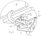
Im dargestellten Ausführungsbeispiel ist weiters ein nicht notwendigerweise verwendeter Mechanismus zur Schaffung einer Gegenkraft beim nach hinten lehnen vorgesehen: zwischen einer Sitzlauffläche
In dieser Führungsöffnung
Aus dem Zusammenhalt der
Wie die
As the
Wenn man im Vergleich dazu die
Da nun verschiedentlich das Anbringen derartiger Flossen und/oder Nuten an entsprechend massiven Stellen eines Drehsessels bzw. Bürosessels nicht immer gut möglich ist, gibt
In etwas anderen Dimensionen als sie der bisher dargestellte Mechanismus aufweist, zeigt die
Die
Es soll noch festgehalten werden, dass die drei Achsen zwischen den seriell angeordneten Bauteilen
Die Erfindung ist nicht auf die dargestellten Beispiele beschränkt, es können die Formen und Dimensionen der Bestandteile Basisteil – Zwischenteil – Zweitarm – Lehnenteil andere Formen und Dimensionen aufweisen und bei anderen Möbeln gänzlich unterschiedlich aufgebaut sein, soferne sich die zwischen ihnen definierten Drehachsen nur in einem Punkt, dem Zentralpunkt
Als Materialien können alle im Möbelbau für Schwenkmechanismen verwendete Materialien herangezogen werden, insbesondere Stahl, gegebenenfalls mit Wälzlagern oder Gleitlagern mit Buchsen aus passendem Lagermetall.As materials, all materials used in furniture for pivoting mechanisms can be used, in particular steel, optionally with rolling bearings or plain bearings with bushings of matching bearing metal.
Claims (7)
Priority Applications (6)
| Application Number | Priority Date | Filing Date | Title |
|---|---|---|---|
| DE102014013560.8A DE102014013560A1 (en) | 2014-09-18 | 2014-09-18 | Furniture with swivel device for a swivel part |
| ATA50328/2015A AT516286A3 (en) | 2014-09-18 | 2015-04-24 | chair |
| PCT/EP2015/071440 WO2016042127A1 (en) | 2014-09-18 | 2015-09-18 | Piece of furniture with a pivoting device for a pivoting part |
| EP15771062.5A EP3193670B1 (en) | 2014-09-18 | 2015-09-18 | Piece of furniture with a pivoting device for a pivoting part |
| US14/859,089 US9968196B2 (en) | 2014-09-18 | 2015-09-18 | Kinematic mechanisms for furniture |
| PL15771062.5T PL3193670T3 (en) | 2014-09-18 | 2015-09-18 | Piece of furniture with a pivoting device for a pivoting part |
Applications Claiming Priority (1)
| Application Number | Priority Date | Filing Date | Title |
|---|---|---|---|
| DE102014013560.8A DE102014013560A1 (en) | 2014-09-18 | 2014-09-18 | Furniture with swivel device for a swivel part |
Publications (1)
| Publication Number | Publication Date |
|---|---|
| DE102014013560A1 true DE102014013560A1 (en) | 2016-03-24 |
Family
ID=55444270
Family Applications (1)
| Application Number | Title | Priority Date | Filing Date |
|---|---|---|---|
| DE102014013560.8A Pending DE102014013560A1 (en) | 2014-09-18 | 2014-09-18 | Furniture with swivel device for a swivel part |
Country Status (4)
| Country | Link |
|---|---|
| EP (1) | EP3193670B1 (en) |
| AT (1) | AT516286A3 (en) |
| DE (1) | DE102014013560A1 (en) |
| PL (1) | PL3193670T3 (en) |
Cited By (2)
| Publication number | Priority date | Publication date | Assignee | Title |
|---|---|---|---|---|
| EP3476254A1 (en) | 2017-10-25 | 2019-05-01 | EB-invent GmbH | Seating furniture, in particular an office chair |
| JPWO2018116386A1 (en) * | 2016-12-20 | 2019-10-24 | コクヨ株式会社 | Chair and chair cover member |
Families Citing this family (1)
| Publication number | Priority date | Publication date | Assignee | Title |
|---|---|---|---|---|
| DE102021104004A1 (en) | 2021-02-19 | 2022-08-25 | Eb-Invent Gmbh | seating furniture |
Family Cites Families (13)
| Publication number | Priority date | Publication date | Assignee | Title |
|---|---|---|---|---|
| US3141669A (en) | 1963-04-26 | 1964-07-21 | Chul Yun | Hoop device |
| US4254990A (en) | 1979-03-13 | 1981-03-10 | Kelley Eugene M | Stabilized oscillating chair |
| DE3660649D1 (en) | 1985-08-07 | 1988-10-13 | Contactos Handel Gmbh | Exercise device |
| US5342244A (en) | 1993-01-08 | 1994-08-30 | Nelson Kevin R | Human-powered gyroscope |
| DE29617332U1 (en) * | 1996-10-05 | 1997-01-23 | Nikowitz, Axel, 47269 Duisburg | Device for moving bodies |
| EP0884964B1 (en) | 1996-10-11 | 2002-06-05 | Giroflex-Entwicklungs-AG | Chair, specially an office chair |
| DE19915003A1 (en) * | 1999-04-01 | 2000-10-05 | Michael Stips | Chair for work machines or training devices, or for use as vehicle seat; has movable seat underlay connected to support unit, and having support structure and movable seat part |
| US6988951B1 (en) | 2002-01-23 | 2006-01-24 | Newman Sven D | Floating machine |
| US7478576B2 (en) | 2005-03-22 | 2009-01-20 | Ross-Hime Designs, Inc. | Robotic manipulator |
| US8662586B2 (en) | 2006-10-10 | 2014-03-04 | Hector Serber | Dynamically balanced seat assembly having independently and arcuately movable backrest and method |
| KR100950812B1 (en) | 2007-11-12 | 2010-04-02 | 김옥근 | Simulator |
| DE102012002400B4 (en) | 2011-03-17 | 2020-06-18 | Eb-Invent Gmbh | manipulator |
| DE102012212121A1 (en) * | 2012-07-11 | 2014-01-16 | Eb-Invent Gmbh | seat device |
-
2014
- 2014-09-18 DE DE102014013560.8A patent/DE102014013560A1/en active Pending
-
2015
- 2015-04-24 AT ATA50328/2015A patent/AT516286A3/en not_active Application Discontinuation
- 2015-09-18 EP EP15771062.5A patent/EP3193670B1/en active Active
- 2015-09-18 PL PL15771062.5T patent/PL3193670T3/en unknown
Cited By (4)
| Publication number | Priority date | Publication date | Assignee | Title |
|---|---|---|---|---|
| JPWO2018116386A1 (en) * | 2016-12-20 | 2019-10-24 | コクヨ株式会社 | Chair and chair cover member |
| EP3560385A4 (en) * | 2016-12-20 | 2020-08-12 | Kokuyo Co., Ltd. | CHAIR AND CHAIR COVER ELEMENT |
| US10842276B2 (en) | 2016-12-20 | 2020-11-24 | Kokuyo Co., Ltd. | Chair and cover member of the chair |
| EP3476254A1 (en) | 2017-10-25 | 2019-05-01 | EB-invent GmbH | Seating furniture, in particular an office chair |
Also Published As
| Publication number | Publication date |
|---|---|
| EP3193670C0 (en) | 2025-01-22 |
| EP3193670A1 (en) | 2017-07-26 |
| PL3193670T3 (en) | 2025-04-28 |
| EP3193670B1 (en) | 2025-01-22 |
| AT516286A2 (en) | 2016-04-15 |
| AT516286A3 (en) | 2016-07-15 |
Similar Documents
| Publication | Publication Date | Title |
|---|---|---|
| DE102012107778B4 (en) | Chair, especially office chair | |
| EP3007590A1 (en) | Chair | |
| WO2016042127A1 (en) | Piece of furniture with a pivoting device for a pivoting part | |
| WO2008022704A1 (en) | Convertible seating/lounge chair | |
| DE202011000805U1 (en) | Chair with tilting and torsionsbeweglicher seat | |
| EP3476254B1 (en) | Seating furniture, in particular an office chair | |
| DE102014013560A1 (en) | Furniture with swivel device for a swivel part | |
| DE102019113313A1 (en) | Seating with stand-up aid | |
| DE102015111016B4 (en) | Chair with a synchronous mechanism for synchronous adjustment of the chair carrier when the backrest is swiveled | |
| DE3421550C2 (en) | ||
| DE2048460A1 (en) | Rotating or tilting device for a tiltable chair seat | |
| DE102010033021B4 (en) | seating | |
| WO2022174945A1 (en) | Seating furniture | |
| AT509542B1 (en) | JOINT FITTING FOR SEATING | |
| AT509317B1 (en) | SEATING | |
| DE102015119937B3 (en) | chair | |
| DE202012101606U1 (en) | seating | |
| DE701339C (en) | Adjustment device for two crossing frame parts of an adjustable seat reclining furniture | |
| DE102010020225B4 (en) | Fitting for adjusting a backrest | |
| DE29800216U1 (en) | Adjustable couch | |
| EP4138612A1 (en) | Chair | |
| EP3278690B1 (en) | Tilt limiting device for limiting the tilting movement of a four-legged chair | |
| DE102018005745A1 (en) | Backrest for seating | |
| DE681593C (en) | Lounge furniture | |
| DE102015009888B4 (en) | Seat device with swiveling seat part and synchronously swiveling backrest |
Legal Events
| Date | Code | Title | Description |
|---|---|---|---|
| R012 | Request for examination validly filed |