DE102012212121A1 - seat device - Google Patents
seat device Download PDFInfo
- Publication number
- DE102012212121A1 DE102012212121A1 DE102012212121.8A DE102012212121A DE102012212121A1 DE 102012212121 A1 DE102012212121 A1 DE 102012212121A1 DE 102012212121 A DE102012212121 A DE 102012212121A DE 102012212121 A1 DE102012212121 A1 DE 102012212121A1
- Authority
- DE
- Germany
- Prior art keywords
- seat
- desk
- seat structure
- seat device
- axis
- Prior art date
- Legal status (The legal status is an assumption and is not a legal conclusion. Google has not performed a legal analysis and makes no representation as to the accuracy of the status listed.)
- Withdrawn
Links
Images


Classifications
-
- A—HUMAN NECESSITIES
- A47—FURNITURE; DOMESTIC ARTICLES OR APPLIANCES; COFFEE MILLS; SPICE MILLS; SUCTION CLEANERS IN GENERAL
- A47C—CHAIRS; SOFAS; BEDS
- A47C7/00—Parts, details, or accessories of chairs or stools
- A47C7/50—Supports for the feet or the legs
- A47C7/506—Supports for the feet or the legs of adjustable type
- A47C7/5066—Supports for the feet or the legs of adjustable type by rotation
-
- A—HUMAN NECESSITIES
- A47—FURNITURE; DOMESTIC ARTICLES OR APPLIANCES; COFFEE MILLS; SPICE MILLS; SUCTION CLEANERS IN GENERAL
- A47C—CHAIRS; SOFAS; BEDS
- A47C1/00—Chairs adapted for special purposes
- A47C1/02—Reclining or easy chairs
- A47C1/031—Reclining or easy chairs having coupled concurrently adjustable supporting parts
- A47C1/032—Reclining or easy chairs having coupled concurrently adjustable supporting parts the parts being movably-coupled seat and back-rest
-
- A—HUMAN NECESSITIES
- A47—FURNITURE; DOMESTIC ARTICLES OR APPLIANCES; COFFEE MILLS; SPICE MILLS; SUCTION CLEANERS IN GENERAL
- A47C—CHAIRS; SOFAS; BEDS
- A47C1/00—Chairs adapted for special purposes
- A47C1/02—Reclining or easy chairs
- A47C1/031—Reclining or easy chairs having coupled concurrently adjustable supporting parts
- A47C1/034—Reclining or easy chairs having coupled concurrently adjustable supporting parts the parts including a leg-rest or foot-rest
- A47C1/0342—Reclining or easy chairs having coupled concurrently adjustable supporting parts the parts including a leg-rest or foot-rest in combination with movable backrest-seat unit or back-rest
- A47C1/0347—Reclining or easy chairs having coupled concurrently adjustable supporting parts the parts including a leg-rest or foot-rest in combination with movable backrest-seat unit or back-rest characterised by the backrest-seat unit or back-rest slidingly movable in the base frame, e.g. by rollers
-
- A—HUMAN NECESSITIES
- A47—FURNITURE; DOMESTIC ARTICLES OR APPLIANCES; COFFEE MILLS; SPICE MILLS; SUCTION CLEANERS IN GENERAL
- A47C—CHAIRS; SOFAS; BEDS
- A47C3/00—Chairs characterised by structural features; Chairs or stools with rotatable or vertically-adjustable seats
- A47C3/02—Rocking chairs
- A47C3/025—Rocking chairs with seat, or seat and back-rest unit elastically or pivotally mounted in a rigid base frame
- A47C3/0257—Rocking chairs with seat, or seat and back-rest unit elastically or pivotally mounted in a rigid base frame slidingly movable in the base frame, e.g. by rollers
-
- A—HUMAN NECESSITIES
- A47—FURNITURE; DOMESTIC ARTICLES OR APPLIANCES; COFFEE MILLS; SPICE MILLS; SUCTION CLEANERS IN GENERAL
- A47C—CHAIRS; SOFAS; BEDS
- A47C7/00—Parts, details, or accessories of chairs or stools
- A47C7/002—Chair or stool bases
- A47C7/004—Chair or stool bases for chairs or stools with central column, e.g. office chairs
-
- A—HUMAN NECESSITIES
- A47—FURNITURE; DOMESTIC ARTICLES OR APPLIANCES; COFFEE MILLS; SPICE MILLS; SUCTION CLEANERS IN GENERAL
- A47C—CHAIRS; SOFAS; BEDS
- A47C7/00—Parts, details, or accessories of chairs or stools
- A47C7/002—Chair or stool bases
- A47C7/006—Chair or stool bases with castors
-
- A—HUMAN NECESSITIES
- A47—FURNITURE; DOMESTIC ARTICLES OR APPLIANCES; COFFEE MILLS; SPICE MILLS; SUCTION CLEANERS IN GENERAL
- A47C—CHAIRS; SOFAS; BEDS
- A47C7/00—Parts, details, or accessories of chairs or stools
- A47C7/50—Supports for the feet or the legs
- A47C7/506—Supports for the feet or the legs of adjustable type
- A47C7/5062—Supports for the feet or the legs of adjustable type rectilinearly
-
- A—HUMAN NECESSITIES
- A47—FURNITURE; DOMESTIC ARTICLES OR APPLIANCES; COFFEE MILLS; SPICE MILLS; SUCTION CLEANERS IN GENERAL
- A47C—CHAIRS; SOFAS; BEDS
- A47C7/00—Parts, details, or accessories of chairs or stools
- A47C7/54—Supports for the arms
Landscapes
- Health & Medical Sciences (AREA)
- Dentistry (AREA)
- General Health & Medical Sciences (AREA)
- Chairs For Special Purposes, Such As Reclining Chairs (AREA)
Abstract
Die Erfindung betrifft eine Schreibtisch-Sitzvorrichtung umfassend ein Grundgestell (2) mit einem Fußkreuz (20) und eine Sitzstruktur (3) mit einer Sitzfläche (30) und einer Rückenlehne (31), wobei eine Schwenkmechanik (4, 104, 204) vorgesehen ist, mittels der die Sitzstruktur (3) an dem Grundgestell (2) um eine horizontale Schwenkachse (I) zwischen einer Arbeits- und einer Liegestellung verschwenkbar gelagert ist, und wobei die Schwenkachse (I) bezüglich des Grundgestells (2) ortsfest oberhalb der Sitzfläche (30) zumindest annähernd im Bereich eines Schwerpunkts der Sitzstruktur (3) samt einer bestimmungsgemäß die Sitzstruktur (3) nutzenden Person angeordnet ist.The invention relates to a desk seat device comprising a base frame (2) with a base (20) and a seat structure (3) with a seat surface (30) and a backrest (31), a swivel mechanism (4, 104, 204) being provided , by means of which the seat structure (3) is pivotably mounted on the base frame (2) about a horizontal pivot axis (I) between a working and a lying position, and wherein the pivot axis (I) is stationary above the seat surface (2) with respect to the base frame (2) 30) is arranged at least approximately in the area of a center of gravity of the seat structure (3) together with a person who uses the seat structure (3) as intended.
Description
Die Erfindung betrifft eine Schreibtisch-Sitzvorrichtung umfassend ein Grundgestell mit einem Fußkreuz und eine Sitzstruktur mit einer Sitzfläche und einer Rückenlehne.The invention relates to a desk-seat device comprising a base frame with a base and a seat structure with a seat and a backrest.
Als Schreibtisch-Sitzvorrichtungen werden im Zusammenhang mit der Anmeldung Sitzvorrichtungen bezeichnet, bei welchen eine Höhe der Sitzfläche, Abmessungen und dergleichen auf die Benutzung an einem Schreibtisch optimiert ist. Derartige Schreibtisch-Sitzvorrichtungen werden im Zusammenhang mit der Anmeldung auch als Büro-Arbeitsstuhl oder kurz Bürostuhl bezeichnet. Anforderungen an derartige Sitzvorrichtungen sind beispielsweise in
In den letzten Jahren hat sich durch zahlreiche wissenschaftliche Studien die Erkenntnis verfestigt, dass die Leistungsfähigkeit eines Berufstätigen mit einem langen Arbeitstag durch einen kurzen Schlaf, oft als Tagschlaf oder Kraftnickerchen (Engl. „Power napping“) bezeichnet‚ deutlich gesteigert werden kann. Es ist daher bekannt, sogenannte Schlafräume in einem Büro vorzusehen. Weiter sind Vorrichtungen bekannt, mit welchem sich ein Arbeitstisch oder ein Bürostuhl in eine Liegevorrichtung für einen kurzen Schlaf umrüsten lassen. Ein derartiges Umrüsten ist jedoch in der Regel mit einem großen Aufwand verbunden, sodass der hohe Umrüstaufwand dem Ziel entgegenstehen, einen kurzen Schlaf dem Arbeitenden in einer kurzen Ruhepause zu ermöglichen.In recent years, numerous scientific studies have confirmed that the ability of a working person with a long working day can be significantly increased by a short sleep, often called daytime sleep or power napping. It is therefore known to provide so-called bedrooms in an office. Furthermore, devices are known with which a work table or an office chair can be converted into a reclining device for a short sleep. Such retooling, however, is usually associated with a great deal of effort, so that the high conversion effort precludes the goal to allow a short sleep the worker in a short break.
Es ist daher eine Aufgabe der Erfindung, eine Schreibtisch-Sitzvorrichtung zu schaffen, welche eine Nutzung in einer Liegestellung ermöglicht, ohne dass hierfür ein hoher Umrüstaufwand erforderlich ist. It is therefore an object of the invention to provide a desk-seat device, which allows use in a lying position, without requiring a high conversion effort is required.
Diese Aufgabe wird gelöst durch eine Schreibtisch-Sitzvorrichtung umfassend ein Grundgestell mit einem Fußkreuz und eine Sitzstruktur mit einer Sitzfläche und einer Rückenlehne, wobei eine Schwenkmechanik vorgesehen ist, mittels der die Sitzstruktur an dem Grundgestell um eine horizontale Schwenkachse zwischen einer Arbeits- und einer Liegestellung verschwenkbar gelagert ist, und wobei die Schwenkachse bezüglich des Grundgestells ortsfest oberhalb der Sitzfläche zumindest annähernd im Bereich eines Schwerpunkts der Sitzstruktur samt einer bestimmungsgemäß die Sitzstruktur nutzenden Person angeordnet ist.This object is achieved by a desk-seat device comprising a base frame with a base and a seat structure with a seat and a backrest, wherein a pivot mechanism is provided, by means of which the seat structure on the base frame about a horizontal pivot axis between a working and a lying position is mounted, and wherein the pivot axis is arranged with respect to the base frame stationary above the seat at least approximately in the region of a center of gravity of the seat structure together with a designated person using the seat structure.
In der Arbeitsstellung ist die Sitzvorrichtung ohne Einschränkungen an einem Schreibtisch nutzbar. Eine Verschwenkbewegung ist mindestens zwischen der Arbeits- und der Liegestellung möglich. Dabei ist in einer Ausgestaltung auch ein Verschwenken in eine beliebige Zwischenposition möglich. Durch die Anordnung der Schwenkachse im Schwerpunkt wirken keine Drehmomente aufgrund der Schwerkraft auf die Sitzstruktur ein. Die Lage der Sitzstruktur ist somit in jeder Schwenkstellung der Sitzstruktur um die Schwenkachse, auch als Neigestellung bezeichnet, stabil. Damit ist es möglich, auf aufwendige Feststellmechanismen zu verzichten. In einer Ausgestaltung sind jedoch zusätzliche Feststellmechanismen zur Fixierung der Sitzstruktur in einer gewünschten Neigestellung vorgesehen. In the working position, the seat device can be used without restrictions at a desk. A pivoting movement is possible at least between the working and the lying position. In one embodiment, pivoting into any intermediate position is also possible. Due to the arrangement of the pivot axis in the center of gravity, no torques due to gravity act on the seat structure. The position of the seat structure is thus stable in any pivoting position of the seat structure about the pivot axis, also referred to as tilting position. This makes it possible to dispense with expensive locking mechanisms. In one embodiment, however, additional locking mechanisms for fixing the seat structure are provided in a desired tilt position.
Eine Verschwenkbewegung der Sitzstruktur ist mit geringem Kraftaufwand, beispielsweise durch Abstützung an einer Armlehne der Sitzvorrichtung möglich. Die Verschwenkbewegung wird daher in einer Ausgestaltung manuell durch einen Nutzer eingeleitet und ausgeführt. In einer anderen Ausgestaltung ist mindestens ein Antrieb und/oder eine Bremse vorgesehen, um die Sitzstruktur zu verschwenken und/oder in einer bestimmten Position zu arretieren. Die Verschwenkposition über die Maximalstellungen, d. h. über die Arbeitsstellung und/oder über die Liegestellung hinaus, ist in vorteilhaften Ausgestaltungen durch Anschläge verhindert. Aufgrund der Anordnung der Schwenkachse oberhalb der Sitzfläche ist ein Überschlagen der Sitzstruktur selbst bei einem Ausfall der Bremsen und/oder ohne Begrenzung sicher verhindert. Da der Schwerpunkt der Sitzstruktur – ggf. mit einer bestimmungsgemäß die Sitzstruktur nutzenden Person – bei einer Verschwenkbewegung zumindest annähernd ortsfest verbleibt, besteht auch keine Gefahr eines Kippens der Sitzvorrichtung um eine Aufstellpunkt des Fußkreuz beim Verschwenken. A pivoting movement of the seat structure is possible with little effort, for example by support on an armrest of the seat device. The pivoting movement is therefore initiated and executed manually in one embodiment by a user. In another embodiment, at least one drive and / or a brake is provided to pivot the seat structure and / or to lock in a certain position. The pivoting position over the maximum positions, d. H. Beyond the working position and / or the lying position, is prevented in advantageous embodiments by attacks. Due to the arrangement of the pivot axis above the seat, overturning of the seat structure is reliably prevented even in the event of a failure of the brakes and / or without limitation. Since the center of gravity of the seat structure-possibly with a person using the seat structure as intended-remains at least approximately stationary during a pivoting movement, there is also no risk of tilting of the seat device about an erection point of the base during pivoting.
Die Schwenkbewegung um die zumindest annähernd im Schwerpunkt liegende Schwenkachse führt auch dazu, dass bei einer Verschwenkbewegung sich ein Gefühl der Entspannung bei einer die Sitzvorrichtung nutzenden Person einstellt. The pivoting movement about the pivot axis lying at least approximately in the center of gravity also leads to a feeling of relaxation in the case of a pivoting movement in the case of a person using the seat device.
Das Fußkreuz umfasst in einer Ausgestaltung Rollen, mittels welchen die Sitzvorrichtung verfahrbar ist. Weiter ist einer Ausgestaltung vorgesehen, dass die Sitzstruktur und das Grundgestell höhenverstellbar verbunden sind, beispielsweise mittels einer Gasdruckfeder-Einrichtung. Da bei einer Schwenkbewegung zwischen der Arbeits- und der Liegestellung keine Verschiebung der Schwenkachse relativ zu dem Grundgestell erfolgt, wird trotz einer Höhenverstellbarkeit der Sitzstruktur relativ zu dem Grundgestell von einer ortsfesten Schwenkachse gesprochen. In einer weiteren Ausgestaltung ist zwischen der Sitzvorrichtung und dem Grundgestell eine Wippmechanik für ein dynamisches Sitzen in der Arbeitsstellung vorgesehen.In one embodiment, the base comprises rollers by means of which the seat device can be moved. Furthermore, an embodiment is provided that the seat structure and the base frame are connected vertically adjustable, for example by means of a gas spring device. Since there is no displacement of the pivot axis relative to the base frame in a pivoting movement between the working and the lying position, despite a height adjustability of the seat structure is spoken relative to the base frame of a fixed pivot axis. In a further embodiment, a tilt mechanism for a dynamic sitting in the working position is provided between the seat device and the base frame.
Der Schwerpunkt der Sitzstruktur, gegebenenfalls samt einer die Sitzstruktur bestimmungsgemäß nutzenden Person, ist je nach Gewicht der Sitzfläche und/oder Rückenlehne und damit deren Einfluss auf die Schwerpunktslage für eine Vielzahl an möglichen Nutzern nahezu gleich. Um eine Anpassung an verschiedene Personen zu ermöglichen, sind in einer Ausgestaltung Ausgleichsgewichte vorgesehen. The center of gravity of the seat structure, possibly including one of the seat structure According to the intended use of the person, depending on the weight of the seat and / or back and thus their influence on the center of gravity for a large number of possible users almost the same. In order to allow adaptation to different people, balancing weights are provided in one embodiment.
In einer Ausgestaltung ist vorgesehen, dass die Sitzstruktur einen Sitzstrukturträger umfasst. Der Sitzstrukturträger dient als Halteeinrichtung für die Sitzfläche und die Rückenlehne. Dabei ist in einer vorteilhaften Ausgestaltung die Sitzfläche und/oder die Rückenlehne relativ zu der Schwenkachse verstellbar und in mindestens zwei unterschiedlichen Positionen fixierbar an dem Sitzstrukturträger gelagert. Durch die Verstellbarkeit der Sitzfläche und/oder der Rückenlehne relativ zu der Schwenkachse ist eine Justierung der Sitzvorrichtung für einen bestimmten Anwendungsfall durch Verlagerung des Schwerpunkts in die Schwenkachse möglich. In one embodiment, it is provided that the seat structure comprises a seat structure support. The seat support serves as a holding device for the seat and the backrest. In this case, in an advantageous embodiment, the seat surface and / or the backrest is adjustable relative to the pivot axis and mounted in at least two different positions fixed to the seat structure support. Due to the adjustability of the seat and / or the backrest relative to the pivot axis an adjustment of the seat device for a particular application by shifting the center of gravity in the pivot axis is possible.
In einer weiteren Ausgestaltung ist vorgesehen, dass die Sitzfläche und die Rückenlehne für eine Übertragung einer Verstellbewegung der Rückenlehne auf die Sitzfläche verbunden sind. Dabei sind in einer Ausgestaltung die Sitzfläche und die Rückenlehne starr miteinander verbunden. Als „starre Verbindung“ wird eine mechanische Verbindung bezeichnet, bei welchen die Bauteile idealerweise keine Relativbewegung zueinander ausführen. In anderen Ausgestaltungen sind die Sitzfläche und die Rückenlehne elastisch verbunden, sodass über einen kleinen, definierbaren Winkelbereich eine Relativbewegung zwischen der Sitzfläche und der Rückenlehne möglich ist. Dadurch ist beispielsweise bei einer Nutzung der Sitzvorrichtung in einer Arbeitsstellung eine Ausgleichsbewegung möglich. In einer weiteren Ausgestaltung ist vorgesehen, dass zumindest bei einem Verschwenken der Sitzstruktur um die Schwenkachse die Sitzfläche und die Rückenlehne starr verbunden sind, um eine Relativbewegung zwischen Sitzfläche und Rückenlehne bei einem Verschwenken um die Schwenkachse und damit eine Verlagerung des Schwerpunkts bei einem Verschwenken zu verhindern. Die starre Verbindung wird dabei in einer Ausgestaltung durch eine geeignete Vorrichtung automatisch bei der Verschwenkbewegung um die Schwenkachse bewirkt. In anderen Ausgestaltungen ist vorgesehen, dass die Teile manuell durch einen Nutzer verbunden werden. Dabei ist in einer Ausgestaltung vorgesehen, dass erst nach einer starren Verbindung der Teile eine Schwenkbewegung um die Schwenkachse freigegeben ist. In a further embodiment it is provided that the seat surface and the backrest are connected to the seat surface for a transmission of an adjustment movement of the backrest. In one embodiment, the seat and the backrest are rigidly connected. As a "rigid connection" a mechanical connection is referred to, in which the components ideally perform no relative movement to each other. In other embodiments, the seat and the backrest are elastically connected, so that over a small, definable angle range, a relative movement between the seat and the backrest is possible. As a result, for example when using the seat device in a working position, a compensation movement is possible. In a further embodiment, it is provided that at least during a pivoting of the seat structure about the pivot axis, the seat and the backrest are rigidly connected to prevent a relative movement between the seat and backrest upon pivoting about the pivot axis and thus a displacement of the center of gravity during pivoting , The rigid connection is effected in one embodiment by a suitable device automatically during the pivoting movement about the pivot axis. In other embodiments, it is provided that the parts are connected manually by a user. It is provided in one embodiment that only after a rigid connection of the parts a pivoting movement is released about the pivot axis.
In einer Ausgestaltung der Schreibtisch-Sitzvorrichtung umfasst die Schwenkmechanik zwei dem Grundgestell zugeordnete, seitlich der Sitzstruktur angeordnete Stützelemente und zwei der Sitzstruktur zugeordnete, an den Stützelementen schwenkbar gelagerte Schwingen. Als der „Sitzstruktur zugeordnet“ wird im Zusammenhang mit der Anmeldung sowohl eine mechanische Verbindung der Schwingen mit Teilen der Sitzstruktur, insbesondere mit dem Sitzstrukturträger, als auch eine einteilige Ausgestaltung der Schwingen mit Teilen der Sitzstruktur, insbesondere mit dem Sitzstrukturträger, bezeichnet. In einer Ausgestaltung sind zwei dem Grundgestell zugeordnete seitliche Armlehnen vorgesehen, wobei die Armlehnen als Stützelemente fungieren, an welchen die Schwingen schwenkbar angelenkt sind.In one embodiment of the desk-seat device, the swivel mechanism comprises two support elements assigned to the base frame, arranged laterally of the seat structure, and two rockers associated with the seat structure and pivotably mounted on the support elements. In connection with the application, a "mechanical connection of the rockers with parts of the seat structure, in particular with the seat structure support, as well as a one-part design of the rockers with parts of the seat structure, in particular with the seat structure support, are referred to as the" seat structure assigned ". In one embodiment, two of the base frame associated side armrests are provided, the armrests act as support elements on which the wings are pivotally articulated.
In einer anderen Ausgestaltung der Schreibtisch-Sitzvorrichtung umfasst die Schwenkmechanik mindestens zwei konzentrisch angeordnete Bogenführungen. Je nach gewünschtem Schwenkwinkel werden mindestens zwei konzentrisch angeordnete, geschlossene Kreisführungen oder offene Bogenführungen, im Folgenden unter Bogenführungen zusammengefasst, vorgesehen. Die Bogenführungen sind auf Rollen oder in Gegenführungen verschieblich gelagert, sodass die Sitzstruktur eine Schwenkbewegung um die Achse vollführt, die durch die beiden Mittelpunkte definiert ist. In vorteilhaften Ausgestaltungen ist dabei vorgesehen, dass die zwei Bogenführungen der Sitzstruktur zugeordnet sind und in einer dem Grundgestell zugeordneten Gegenführung verschieblich gelagert sind. In einer Ausgestaltung ist ein Verlauf der Biegelinie der zwei Bogenführungen für eine Verschwenkbewegung optimiert ist. Die zwei Bogenführungen sind zu diesem Zweck in einer Ausgestaltung als Kreisbogenführungen gestaltet. In einer anderen Ausgestaltung weisen die Bogenführungen eine Biegelinie auf, welche abschnittsweise von einer Kreisbahn abweicht. Durch geeignete Wahl der Biegelinie ist in einer Ausgestaltung ein Kraftaufwand zu Beginn einer Verschwenkbewegung aus der Arbeitsstellung und/oder aus der Liegestellung erhöht. Alternativ oder zusätzlich ist durch geeignete Wahl der Biegelinie in einer anderen Ausgestaltung vorgesehen, dass die Sitzstruktur ohne äußere Krafteinwirkung in die Arbeitsstellung und/oder in die Liegestellung gezwungen ist. Der Verlauf der Biegelinie ist durch den Fachmann ohne Schwierigkeiten geeignet wählbar, wobei der Schwerpunkt zumindest annähernd ortsfest verbleibt.In another embodiment of the desk-seat device, the pivot mechanism comprises at least two concentrically arranged sheet guides. Depending on the desired pivoting angle, at least two concentrically arranged, closed circular guides or open sheet guides, in the following summarized under sheet guides, are provided. The sheet guides are slidably mounted on rollers or counter-guides, so that the seat structure performs a pivoting movement about the axis, which is defined by the two centers. In advantageous embodiments, it is provided that the two sheet guides are associated with the seat structure and are slidably mounted in a counter guide associated with the base frame. In one embodiment, a course of the bending line of the two sheet guides is optimized for a pivoting movement. The two sheet guides are designed for this purpose in one embodiment as circular arc guides. In another embodiment, the sheet guides on a bending line, which differs in sections from a circular path. By a suitable choice of the bending line, in one embodiment, a force is increased at the beginning of a pivoting movement from the working position and / or from the lying position. Alternatively or additionally, it is provided by a suitable choice of the bending line in another embodiment, that the seat structure is forced into the working position and / or in the lying position without external force. The course of the bending line can be suitably selected by the person skilled in the art without difficulty, the center of gravity remaining at least approximately stationary.
In noch einer anderen Ausgestaltung der Schreibtisch-Sitzvorrichtung umfasst die Schwenkmechanik zwei Gelenkeinrichtungen, von denen jede mindestens einen Oberarm und einen um eine Armachse drehbar an den Oberarm angelenkten Unterarm aufweist, wobei der Oberarm um eine Basisachse drehbar an dem Grundgestell angelenkt ist, der Unterarm um eine Endachse drehbar an der Sitzstruktur angelenkt ist, die Basisachse, die Armachse und die Endachse jeder Gelenkeinrichtung einander in jeweils einem Zentralpunkt schneiden und die Verbindungslinie der Zentralpunkte die Schwenkachse definiert. In einer Ausgestaltung sind weitere Arme, die um weitere Armachsen, die durch den Zentralpunkt gehen, drehbar sind, vorgesehen, wobei der Unterarm nicht direkt oder unmittelbar an der Sitzstruktur angelenkt ist, sondern die Sitzstruktur zwischen den beiden letzten Armen der zwei Gelenkeinrichtungen, drehbar um deren beiden Endachsen gelagert ist. Eine derartige Schwenkmechanik erlaubt ein Verschwenken um eine nicht körperlich realisierte Schwenkachse. Die Schwenkmechanik ist zu der Schwenkachse versetzt angeordnet. In vorteilhaften Ausgestaltungen ist die Schwenkmechanik platzsparend unterhalb der Sitzfläche angeordnet, ohne dass es hierfür zu einer Beeinträchtigung der Nutzung in der Arbeitsstellung kommt. Zudem ist es möglich, ein Design der Sitzstruktur zu schaffen, welches nicht durch die Schwenkmechanik erzwungen ist.In yet another embodiment of the desk-seat device, the pivot mechanism comprises two hinge devices, each of which has at least one upper arm and a forearm articulated about an arm axis to the upper arm, the upper arm being hinged to the base frame about a base axis, the lower arm an end axis is rotatably hinged to the seat structure, the base axis, the arm axis and the end axis of each hinge device intersect each other in each case a central point and the connecting line of the central points defines the pivot axis. In one embodiment are more Arms which are rotatable about more arm axes that go through the central point, provided, wherein the lower arm is not directly or directly hinged to the seat structure, but the seat structure between the two last arms of the two hinge devices, is rotatably mounted about the two end axes , Such a pivot mechanism allows pivoting about a not physically realized pivot axis. The pivot mechanism is arranged offset to the pivot axis. In advantageous embodiments, the swivel mechanism is arranged to save space below the seat, without this resulting in an impairment of the use in the working position. In addition, it is possible to provide a design of the seat structure, which is not enforced by the pivoting mechanism.
In einer Weiterbildung sind die beiden Gelenkeinrichtungen symmetrisch bezüglich der Symmetrieebene zwischen den beiden Zentralpunkten aufgebaut. Dies ist wegen der einfachen Lagerhaltung und Konstruktion beim Bau und der Wartung vorteilhaft, doch ist dies nicht notwendig. In vorteilhaften Ausgestaltungen ist jedoch zumindest vorgesehen, dass die Endachsen in einer gemeinsamen Normalebene zur Schwenkachse verlaufen und/oder dass die Basisachsen in einer gemeinsamen Ebene liegen. In a development, the two joint devices are constructed symmetrically with respect to the plane of symmetry between the two central points. This is advantageous for ease of storage and construction during construction and maintenance, but this is not necessary. In advantageous embodiments, however, it is at least provided that the end axes extend in a common normal plane to the pivot axis and / or that the base axes lie in a common plane.
In einer weiteren Ausgestaltung der Schreibtisch-Sitzvorrichtung umfasst die Sitzstruktur eine zwischen einer Gebrauchsposition und einer Verstauposition verstellbare Beinauflage. Die Bein- oder Fußauflage ermöglicht ein Ablegen der Unterbeine und/oder der Füße in einer Liegestellung. In der Gebrauchsposition ist die Beinauflage in einer Ausgestaltung in einer Ebene mit der Sitzfläche. In einer anderen Ausgestaltung ist die Beinauflage bezüglich der Sitzfläche in der Gebrauchsposition abgewinkelt. Die Beinauflage ist in einer Ausgestaltung mit dem Schwenkmechanismus der Sitzstruktur gekoppelt, sodass beim Verschwenken der Sitzstruktur in die Liegestellung die Beinauflage in die Gebrauchsposition verstellt wird. In anderen Ausgestaltungen sind die Verstellbewegungen der Sitzstruktur und der Beinauflage nicht gekoppelt, sodass beispielsweise die Beinauflage auch in der Arbeitsstellung in eine Gebrauchsposition gebracht werden kann.In a further embodiment of the desk-seat device, the seat structure comprises an adjustable between a use position and a stowage leg rest. The leg or footrest allows the lower legs and / or feet to be stored in a lying position. In the use position, the leg rest is in one embodiment in a plane with the seat. In another embodiment, the leg rest is angled with respect to the seat in the use position. The leg rest is coupled in one embodiment with the pivot mechanism of the seat structure, so that when pivoting the seat structure in the lying position, the leg rest is adjusted to the use position. In other embodiments, the adjustment movements of the seat structure and the leg rest are not coupled, so that, for example, the leg rest can be brought into a working position even in the working position.
In einer Weiterbildung ist vorgesehen, dass die Beinauflage verschwenkbar an der Sitzstruktur angelenkt ist. Dabei ist in einer Ausgestaltung die Beinauflage um eine an einem vorderen Ende der Sitzfläche angeordnete Achse verschwenkbar angelenkt. Ein Verschwenken erfolgt dabei in einer Ausgestaltung mittels eines Klappmechanismus mit einem von der Sitzfläche nach unten abragenden Stopper-Element, welches die Beinauflage in einer Liegestellung der Sitzstruktur entgegen der Schwerkraft in einer Gebrauchsposition hält. In a further development, it is provided that the leg rest is articulated pivotably on the seat structure. In this case, in one embodiment, the leg rest is articulated pivotably about an axis arranged at a front end of the seat surface. In one embodiment, pivoting takes place by means of a folding mechanism with a stopper element projecting downwards from the seat surface, which holds the leg rest against the force of gravity in a lying position in a lying position of the seat structure in a use position.
In einer alternativen Ausgestaltung ist die Beinauflage in einem Schubfach verschieb- und abklappbar gelagert. Dabei ist die Beinauflage in einer Ausgestaltung mittels einer Zwangskraft belastet, welche bei einem Ausziehen der Beinauflage aus dem Schubfach ein Abklappen bewirkt.In an alternative embodiment, the legrest is slidably mounted and hinged in a drawer. In one embodiment, the leg rest is loaded by means of a constraining force, which causes it to fold down when the leg rest is pulled out of the drawer.
Weitere Vorteile der Erfindung ergeben sich aus den Unteransprüchen und aus der nachfolgenden Beschreibung von Ausführungsbeispielen der Erfindung, die in den Zeichnungen schematisch dargestellt sind. Für gleiche oder ähnliche Bauteile werden in den Zeichnungen einheitliche Bezugszeichen verwendet. Als Teil eines Ausführungsbeispiels beschriebene oder dargestellte Merkmale können ebenso in einem anderen Ausführungsbeispiel verwendet werden, um eine weitere Ausführungsform der Erfindung zu erhalten.Further advantages of the invention will become apparent from the subclaims and from the following description of embodiments of the invention, which are shown schematically in the drawings. For identical or similar components, the same reference numbers are used in the drawings. Features described or illustrated as part of one embodiment may also be used in another embodiment to obtain a further embodiment of the invention.
In den Zeichnungen zeigen:In the drawings show:
Die
Die
Die
Die Schreibtisch-Sitzvorrichtung
Die Schreibtisch-Sitzvorrichtungen
Die Schreibtisch-Sitzvorrichtungen
Die Sitzstruktur
Die in den
Die in den
Die bei den vier Ausführungsbeispielen vorgesehenen Schwenkmechaniken
Gemäß dem ersten in den
Die Stützstruktur
Die Schwenkmechanik
Die dargestellte Stützstruktur
Wie in
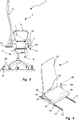
Die in den
Die in
In dem dargestellten Ausführungsbeispiel sind die beiden Gelenkeinrichtungen
Die zwei Gelenkeinrichtungen
In dem dargestellten Ausführungsbeispiel umfasst jede Gelenkeinrichtung zwei Arme, nämlich einen Oberarm
Die Basisachsen
In der Ausführungsform gemäß den
In allen dargestelltem Ausgestaltungen erfolgt eine Verstellbewegung zwischen der Arbeitsstellung und der Liegestellung manuell. Ein Nutzer kann sich zu diesem Zweck beispielsweise an den Armstützen abstützen und durch ein Zurücklehnen eine Verschwenkbewegung in die Liegestellung einleiten. In anderen Ausgestaltungen umfasst die der Schwenkmechanik einen Antrieb oder mehrere Antriebe. Die Antriebe sind dabei entsprechend der Schwenkmechanik geeignet wählbar. In all illustrated embodiments, an adjusting movement between the working position and the lying position is done manually. A user can be supported for this purpose, for example, on the armrests and initiate a pivoting movement in the reclining position by leaning back. In other embodiments, the pivoting mechanism comprises a drive or a plurality of drives. The drives are suitably selected according to the pivoting mechanism.
In einer Ausgestaltung ist eine Zeitschaltuhr mit einer Aufweckfunktion vorgesehen, wobei nach Ablauf einer definierten Zeitspanne ein Nutzer geweckt wird. In einer Ausführungsform ist zu diesem Zweck vorgesehen, dass bei Ablauf der Zeitspanne eine Zwangskraft aufgebracht wird, mittels welcher eine Rückstellung der Sitzstruktur
Die für die Realisierung der einzelnen Schwenkmechaniken
ZITATE ENTHALTEN IN DER BESCHREIBUNG QUOTES INCLUDE IN THE DESCRIPTION
Diese Liste der vom Anmelder aufgeführten Dokumente wurde automatisiert erzeugt und ist ausschließlich zur besseren Information des Lesers aufgenommen. Die Liste ist nicht Bestandteil der deutschen Patent- bzw. Gebrauchsmusteranmeldung. Das DPMA übernimmt keinerlei Haftung für etwaige Fehler oder Auslassungen.This list of the documents listed by the applicant has been generated automatically and is included solely for the better information of the reader. The list is not part of the German patent or utility model application. The DPMA assumes no liability for any errors or omissions.
Zitierte Nicht-PatentliteraturCited non-patent literature
- DIN EN 1335 [0002] DIN EN 1335 [0002]
Claims (14)
Priority Applications (5)
| Application Number | Priority Date | Filing Date | Title |
|---|---|---|---|
| DE102012212121.8A DE102012212121A1 (en) | 2012-07-11 | 2012-07-11 | seat device |
| EP13737809.7A EP2872007B1 (en) | 2012-07-11 | 2013-06-25 | Seat device |
| PL13737809T PL2872007T3 (en) | 2012-07-11 | 2013-06-25 | Seat device |
| PCT/EP2013/063291 WO2014009147A1 (en) | 2012-07-11 | 2013-06-25 | Seat device |
| US14/413,493 US20150196123A1 (en) | 2012-07-11 | 2013-06-25 | Seat device |
Applications Claiming Priority (1)
| Application Number | Priority Date | Filing Date | Title |
|---|---|---|---|
| DE102012212121.8A DE102012212121A1 (en) | 2012-07-11 | 2012-07-11 | seat device |
Publications (1)
| Publication Number | Publication Date |
|---|---|
| DE102012212121A1 true DE102012212121A1 (en) | 2014-01-16 |
Family
ID=48795557
Family Applications (1)
| Application Number | Title | Priority Date | Filing Date |
|---|---|---|---|
| DE102012212121.8A Withdrawn DE102012212121A1 (en) | 2012-07-11 | 2012-07-11 | seat device |
Country Status (5)
| Country | Link |
|---|---|
| US (1) | US20150196123A1 (en) |
| EP (1) | EP2872007B1 (en) |
| DE (1) | DE102012212121A1 (en) |
| PL (1) | PL2872007T3 (en) |
| WO (1) | WO2014009147A1 (en) |
Cited By (2)
| Publication number | Priority date | Publication date | Assignee | Title |
|---|---|---|---|---|
| US10362874B2 (en) | 2015-07-23 | 2019-07-30 | Herman Miller, Inc. | Seating device |
| US11596232B2 (en) | 2019-04-16 | 2023-03-07 | MillerKnoll, Inc. | Chair for active engagement of user |
Families Citing this family (18)
| Publication number | Priority date | Publication date | Assignee | Title |
|---|---|---|---|---|
| CA2927634C (en) * | 2013-10-21 | 2018-08-14 | B/E Aerospace, Inc. | Linearly deployable aircraft seat legrest |
| DE102014013560A1 (en) * | 2014-09-18 | 2016-03-24 | Eb-Invent Gmbh | Furniture with swivel device for a swivel part |
| US10500434B2 (en) * | 2015-02-16 | 2019-12-10 | Kuang Yu Metal Working Co., Ltd. | Exercising device and operating method thereof |
| CN105983207B (en) * | 2015-02-16 | 2019-01-04 | 光昱金属有限公司 | Swinging sports equipment and adjusting method thereof |
| US10092106B2 (en) | 2015-07-14 | 2018-10-09 | La-Z-Boy Incorporated | Recliner and legrest mechanism for a furniture member |
| WO2017206904A1 (en) * | 2016-06-02 | 2017-12-07 | 上海海雁医药科技有限公司 | Pi3k inhibitor, and pharmaceutically acceptable salt, polycrystalline form, and application thereof |
| US9986835B2 (en) | 2016-09-22 | 2018-06-05 | La-Z-Boy Incorporated | Furniture member having cam tilt mechanism |
| US10213021B2 (en) * | 2017-02-24 | 2019-02-26 | Belinda Walters | Mobile chair |
| US10537178B2 (en) | 2017-04-07 | 2020-01-21 | La-Z-Boy Incorporated | Furniture member having flexible seatback |
| US10568428B2 (en) | 2017-04-07 | 2020-02-25 | La-Z-Boy Incorporated | Furniture member having flexible seatback |
| US10383448B1 (en) | 2018-03-28 | 2019-08-20 | Haworth, Inc. | Forward tilt assembly for chair seat |
| US10524575B2 (en) | 2018-04-16 | 2020-01-07 | La-Z-Boy Incorporated | Furniture member with foldable pawl and ratchet assembly |
| US10524574B2 (en) * | 2018-05-18 | 2020-01-07 | La-Z-Boy Incorporated | Furniture member with powered wall-proximity mechanism |
| US10820708B2 (en) | 2018-05-18 | 2020-11-03 | La-Z-Boy Incorporated | Furniture member with wall-proximity mechanism and locking trigger |
| WO2020227658A1 (en) | 2019-05-09 | 2020-11-12 | La-Z-Boy Incorporated | Reclining chaise |
| CN110254314B (en) * | 2019-06-25 | 2020-06-16 | 延锋安道拓座椅有限公司 | Built-in seat leg rest and seat |
| US11197549B1 (en) | 2020-09-28 | 2021-12-14 | La-Z-Boy Incorporated | Wall-proximity furniture member having sync mechanism |
| US12478185B2 (en) | 2022-03-18 | 2025-11-25 | La-Z-Boy Incorporated | Reclining chaise mechanism |
Citations (6)
| Publication number | Priority date | Publication date | Assignee | Title |
|---|---|---|---|---|
| DE29608099U1 (en) * | 1995-05-11 | 1996-07-04 | Kusch & Co Sitzmöbelwerke KG, 59969 Hallenberg | Sitting and reclining furniture |
| EP0885576A2 (en) * | 1997-06-20 | 1998-12-23 | Johannes Uhlenbrock | Seating furniture, particularly office-chair |
| DE10306851A1 (en) * | 2003-02-18 | 2004-08-26 | Dózsa-Farkas, Andras | Office chair has back rest which reclines about axis at ends of L-shaped levers mounted on its base, seat sliding forward in synchronization with back rest and axis maintaining constant position above seat |
| DE202005010953U1 (en) * | 2005-07-12 | 2005-10-13 | BRÜSKE, Joachim | Office chair has back rest attached by rocker arm to mounting at top of support column, arm having slot with curve whose center is located near hip joint of user, seat being mounted on arm which fits into slot |
| CH696379A5 (en) * | 2002-10-15 | 2007-05-31 | Stoll Giroflex Ag | Seating for e.g. office chair, has backrest part which has several mutually adjustable backrest segments and backrest part can be optionally tilted from working position to first or second pre-defined neutral-end position |
| DE102007001194A1 (en) * | 2007-01-05 | 2008-07-10 | Omp S.R.L | Motion coupled Servoeinrichutng for a seat part, in particular a chair |
Family Cites Families (10)
| Publication number | Priority date | Publication date | Assignee | Title |
|---|---|---|---|---|
| FR958120A (en) * | 1950-03-03 | |||
| JPS5628714A (en) * | 1979-08-20 | 1981-03-20 | Tokico Ltd | Locking chair |
| DE4239548A1 (en) * | 1992-11-25 | 1993-04-15 | Juergen Stiewe | Office or work chair - has brackets, rollers, and circular tracks to allow adjustable tilt for seat and backrest |
| JP2992597B2 (en) * | 1996-09-27 | 1999-12-20 | 裕弘 上原 | Desk / chair set that follows changes in sitting posture |
| US5967609A (en) * | 1996-11-18 | 1999-10-19 | Hwe, Inc. | Reclining chair with guide rail system |
| US6106065A (en) * | 1997-10-24 | 2000-08-22 | Reliance Medical Products, Inc. | Examination chair with lifting and tilting mechanism |
| US6450578B1 (en) * | 2000-08-18 | 2002-09-17 | Michael Blake Taggett | Ergonomic chair |
| US7080887B2 (en) * | 2003-08-14 | 2006-07-25 | Taiwan Shin Yeh Enterprise Co., Ltd. | Chair with foldable leg rest |
| AT11784U1 (en) * | 2009-10-14 | 2011-05-15 | Walter Schindlegger | OFFICE CHAIR |
| FR2990336A1 (en) * | 2012-05-09 | 2013-11-15 | Via | JOINT MECHANISM AND ARTICULATED SEAT WITH SYNCHRONOUS MOVEMENT BETWEEN THE SEAT AND THE BACKREST |
-
2012
- 2012-07-11 DE DE102012212121.8A patent/DE102012212121A1/en not_active Withdrawn
-
2013
- 2013-06-25 PL PL13737809T patent/PL2872007T3/en unknown
- 2013-06-25 EP EP13737809.7A patent/EP2872007B1/en not_active Not-in-force
- 2013-06-25 WO PCT/EP2013/063291 patent/WO2014009147A1/en not_active Ceased
- 2013-06-25 US US14/413,493 patent/US20150196123A1/en not_active Abandoned
Patent Citations (6)
| Publication number | Priority date | Publication date | Assignee | Title |
|---|---|---|---|---|
| DE29608099U1 (en) * | 1995-05-11 | 1996-07-04 | Kusch & Co Sitzmöbelwerke KG, 59969 Hallenberg | Sitting and reclining furniture |
| EP0885576A2 (en) * | 1997-06-20 | 1998-12-23 | Johannes Uhlenbrock | Seating furniture, particularly office-chair |
| CH696379A5 (en) * | 2002-10-15 | 2007-05-31 | Stoll Giroflex Ag | Seating for e.g. office chair, has backrest part which has several mutually adjustable backrest segments and backrest part can be optionally tilted from working position to first or second pre-defined neutral-end position |
| DE10306851A1 (en) * | 2003-02-18 | 2004-08-26 | Dózsa-Farkas, Andras | Office chair has back rest which reclines about axis at ends of L-shaped levers mounted on its base, seat sliding forward in synchronization with back rest and axis maintaining constant position above seat |
| DE202005010953U1 (en) * | 2005-07-12 | 2005-10-13 | BRÜSKE, Joachim | Office chair has back rest attached by rocker arm to mounting at top of support column, arm having slot with curve whose center is located near hip joint of user, seat being mounted on arm which fits into slot |
| DE102007001194A1 (en) * | 2007-01-05 | 2008-07-10 | Omp S.R.L | Motion coupled Servoeinrichutng for a seat part, in particular a chair |
Non-Patent Citations (1)
| Title |
|---|
| DIN EN 1335 |
Cited By (3)
| Publication number | Priority date | Publication date | Assignee | Title |
|---|---|---|---|---|
| US10362874B2 (en) | 2015-07-23 | 2019-07-30 | Herman Miller, Inc. | Seating device |
| US11596232B2 (en) | 2019-04-16 | 2023-03-07 | MillerKnoll, Inc. | Chair for active engagement of user |
| US11805905B2 (en) | 2019-04-16 | 2023-11-07 | MillerKnoll, Inc. | Chair for active engagement of user |
Also Published As
| Publication number | Publication date |
|---|---|
| EP2872007B1 (en) | 2016-09-21 |
| WO2014009147A1 (en) | 2014-01-16 |
| US20150196123A1 (en) | 2015-07-16 |
| PL2872007T3 (en) | 2017-04-28 |
| EP2872007A1 (en) | 2015-05-20 |
Similar Documents
| Publication | Publication Date | Title |
|---|---|---|
| EP2872007B1 (en) | Seat device | |
| EP1743612B1 (en) | Wheelchair for disabled persons | |
| EP2374371B1 (en) | Seating furniture with a seat that can be pivoted into a position that assists in standing up | |
| EP3049040A1 (en) | Item of seating furniture | |
| AT12867U1 (en) | seating | |
| EP2070443B1 (en) | Horizontally adjustable armrest | |
| BE1017877A3 (en) | SEATING | |
| EP1721801B1 (en) | Device for protecting passengers on the seat of a chairlift | |
| DE69508135T2 (en) | Relaxation chair | |
| EP3528664A1 (en) | Synchronous chair mechanism and chair having one such | |
| DE19611345A1 (en) | Device for vibrating seat/back-rest unit | |
| WO2002065970A1 (en) | Adjustable seat frame | |
| DE102015111016B4 (en) | Chair with a synchronous mechanism for synchronous adjustment of the chair carrier when the backrest is swiveled | |
| CH661190A5 (en) | ADJUSTABLE CHAIR. | |
| DE202006005139U1 (en) | Sofa bed has back rest which is mounted on levers, allowing it to be moved to increase or decrease width of seat | |
| DE102009051576B4 (en) | seating | |
| DE102009007324A1 (en) | Base device for seating furniture, has intermediate piece arranged between seat and base element, and control device retaining pivot axle in vertical position during vertical movement of base element | |
| DE102020124190A1 (en) | Fitting for seating and / or reclining furniture, seating and / or reclining furniture with the fitting and its use and application | |
| AT509216B1 (en) | FURNITURE | |
| EP4154858A1 (en) | Seating furniture with a standing aid | |
| DE202007006664U1 (en) | Seating furniture for e.g. relax armchair, has gas-pressure spring with adjusting inserting force for adjusting inclination of backrest relative to seating surface defined by seating frame, where force acts over transverse path of backrest | |
| DE3800756C2 (en) | ||
| DE102008015758B4 (en) | Hollywood swing | |
| DE20308069U1 (en) | Armchair with power-operated footrest and backrest has two-armed lever pivoting above and below rake hinge | |
| EP2380460B1 (en) | Back rest with neck support for an office chair and office chair |
Legal Events
| Date | Code | Title | Description |
|---|---|---|---|
| R163 | Identified publications notified | ||
| R119 | Application deemed withdrawn, or ip right lapsed, due to non-payment of renewal fee |