DE102007039408A1 - Crane control system for crane with cable for load lifting by controlling signal tower of crane, has sensor unit for determining cable angle relative to gravitational force - Google Patents
Crane control system for crane with cable for load lifting by controlling signal tower of crane, has sensor unit for determining cable angle relative to gravitational force Download PDFInfo
- Publication number
- DE102007039408A1 DE102007039408A1 DE102007039408A DE102007039408A DE102007039408A1 DE 102007039408 A1 DE102007039408 A1 DE 102007039408A1 DE 102007039408 A DE102007039408 A DE 102007039408A DE 102007039408 A DE102007039408 A DE 102007039408A DE 102007039408 A1 DE102007039408 A1 DE 102007039408A1
- Authority
- DE
- Germany
- Prior art keywords
- crane
- load
- rope
- cable
- control according
- Prior art date
- Legal status (The legal status is an assumption and is not a legal conclusion. Google has not performed a legal analysis and makes no representation as to the accuracy of the status listed.)
- Withdrawn
Links
Classifications
-
- B—PERFORMING OPERATIONS; TRANSPORTING
- B66—HOISTING; LIFTING; HAULING
- B66C—CRANES; LOAD-ENGAGING ELEMENTS OR DEVICES FOR CRANES, CAPSTANS, WINCHES, OR TACKLES
- B66C13/00—Other constructional features or details
- B66C13/18—Control systems or devices
- B66C13/46—Position indicators for suspended loads or for crane elements
-
- B—PERFORMING OPERATIONS; TRANSPORTING
- B66—HOISTING; LIFTING; HAULING
- B66C—CRANES; LOAD-ENGAGING ELEMENTS OR DEVICES FOR CRANES, CAPSTANS, WINCHES, OR TACKLES
- B66C13/00—Other constructional features or details
- B66C13/04—Auxiliary devices for controlling movements of suspended loads, or preventing cable slack
- B66C13/06—Auxiliary devices for controlling movements of suspended loads, or preventing cable slack for minimising or preventing longitudinal or transverse swinging of loads
- B66C13/063—Auxiliary devices for controlling movements of suspended loads, or preventing cable slack for minimising or preventing longitudinal or transverse swinging of loads electrical
-
- B—PERFORMING OPERATIONS; TRANSPORTING
- B66—HOISTING; LIFTING; HAULING
- B66C—CRANES; LOAD-ENGAGING ELEMENTS OR DEVICES FOR CRANES, CAPSTANS, WINCHES, OR TACKLES
- B66C13/00—Other constructional features or details
- B66C13/04—Auxiliary devices for controlling movements of suspended loads, or preventing cable slack
- B66C13/08—Auxiliary devices for controlling movements of suspended loads, or preventing cable slack for depositing loads in desired attitudes or positions
- B66C13/085—Auxiliary devices for controlling movements of suspended loads, or preventing cable slack for depositing loads in desired attitudes or positions electrical
Landscapes
- Engineering & Computer Science (AREA)
- Mechanical Engineering (AREA)
- Automation & Control Theory (AREA)
- Control And Safety Of Cranes (AREA)
- Jib Cranes (AREA)
Abstract
Die vorliegende Erfindung zeigt eine Kransteuerung eines Kranes, welcher mindestens ein Seil zum Heben einer Last aufweist, wobei mindestens eine Sensoreinheit zur Bestimmung eines Seilwinkels relativ zur Gravitationskraftrichtung vorgesehen ist. Weiterhin wird eine Kransteuerung zur Ansteuerung der Stellwerke eines Kranes, welcher mindestens einen ersten und einen zweiten Seilstrang zum Heben der Last aufweist, mit einer Lastpendeldämpfung zur Dämpfung von sphärischen Pendelschwingungen der Last gezeigt, wobei eine erste und eine zweite Sensoreinheit, welche dem ersten und dem zweiten Seilstrang zugeordnet sind, vorgesehen sind, um die jeweiligen Seilwinkel und/oder Seilwinkelgeschwindigkeiten zu bestimmten, und die Lastpendeldämpfung eine Reglung aufweist, in welche die von der ersten und der zweiten Sensoreinheit bestimmten Seilwinkel und/oder Seilwinkelgeschwindigkeiten eingehen. Weiterhin sind ein entsprechender Kran und ein Verfahren gezeigt.The The present invention shows a crane control of a crane which at least one rope for lifting a load, wherein at least a sensor unit for determining a cable angle relative to the gravitational force direction is provided. Furthermore, a crane control for driving the interlockings of a crane, which at least a first and a second cable harness for lifting the load, with a Load swing damping for damping of spherical Pendulum oscillations of the load shown, with a first and a second Sensor unit, which associated with the first and the second cable strand are provided to the respective cable angle and / or rope angular velocities to certain, and the load swing damping has a regulation, in which the determined by the first and the second sensor unit Enter rope angles and / or rope angle velocities. Farther a corresponding crane and a method are shown.
Description
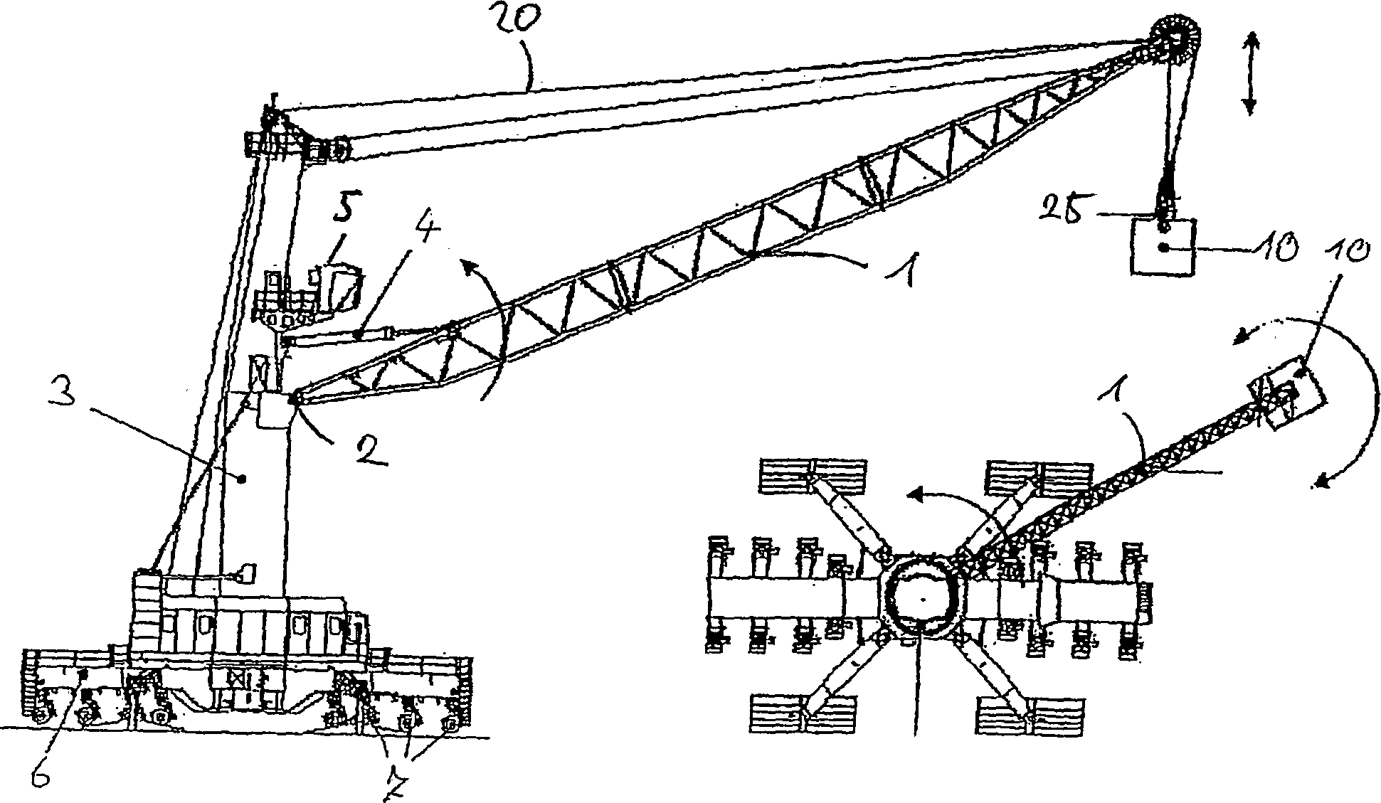
Die vorliegende Erfindung betrifft eine Kransteuerung eines Kranes, welcher mindestens ein Seil zum Heben einer Last aufweist. Weiterhin betrifft die vorliegende Erfindung in einer weiteren Ausführung die Kransteuerung eines Kranes, welcher mindestens einen ersten und einen zweiten Seilstrang zum Heben einer Last aufweist. Die Kransteuerung steuert dabei die Stellwerke des Kranes an. Insbesondere handelt es sich bei dem Kran um einen Auslegerkran, welcher einen um eine horizontale Achse schwenkbaren Ausleger aufweist, der an einem um eine vertikale Achse drehbaren Turm angelenkt ist. Hierzu sind als Stellwerke ein Wippwerk und ein Drehwerk vorgesehen. Das Seil zum Heben der Last läuft dabei über die Spitze des Auslegers, insbesondere über eine oder mehrere dort angeordnete Umlenkrollen, so dass die Last durch ein Drehen des Turms in tangentialer Richtung und durch ein Aufwippen des Auslegers in radialer Richtung bewegt werden kann. Bei der Ausführung der Erfindung mit mindestens einem ersten und einem zweiten Seilstrang verlaufen beide Seilstränge von der Spitze des Auslegers zu einem Aufnahmeelement wie z. B. einem Hacken. Die Länge des Seils ist dabei durch einen entsprechenden Antrieb einstellbar, um die Last in vertikaler Richtung zu bewegen. Insbesondere betrifft die erfindungsgemäße Kransteuerung dabei allgemein Dreh krane, sowie Hafenmobilkrane, Schiffskrane, Off-Shore-Krane, Autokrane und Raupenkrane.The The present invention relates to a crane control of a crane, which has at least one cable for lifting a load. Farther relates to the present invention in a further embodiment the crane control of a crane, which at least a first and a second cable harness for lifting a load. The Crane control controls the interlocking of the crane. Especially If the crane is a jib crane, which is a about a horizontal axis pivotable arm, the on a rotatable about a vertical axis tower is articulated. For this are provided as interlockings a luffing and slewing. The Rope to lift the load runs over the top of the jib, especially over one or more there arranged pulleys, so that the load by turning the Tower in the tangential direction and by a Auflippen the boom can be moved in the radial direction. In the execution the invention with at least a first and a second strand of rope Both strands run from the top of the boom to a receiving element such. B. a hoes. The length the rope is adjustable by a suitable drive, to move the load in a vertical direction. In particular, it concerns the crane control according to the invention in general Cranes, mobile harbor cranes, ship cranes, off-shore cranes, Mobile cranes and crawler cranes.
Aus
Aus
Bei den oben genannten Kransteuerungen werden dabei zur Bestimmung der Lastschwingung Gyroskopeinheiten eingesetzt, welche im Kranhaken angeordnet sind und die Winkelgeschwindigkeit des Seils bestimmen. Der Seilwinkel wird dabei über eine Beobachterschaltung, welche die Bewegung des Seils aufintegriert, bestimmt. Um den dabei entstehenden Offset ausgleichen zu können, wird von einem frei schwingenden Pendel ausgegangen, dessen Ruhestellung einem lotrechten Seilwinkel entspricht. Ein solches Vorgehen ist zwar für die Seilpendeldämpfung gut geeignet, da hierzu vor allem die Bewegungen des Seils bei freiem Schwingen der Last am Seil überwacht werden müssen. Eine Bestimmung der absoluten Ausrichtung des Seils, insbesondere bevor die Last frei schwingen kann, ist bei den bekannten Kransteuerungen jedoch weder vorgesehen noch möglich. Weiterhin hatten bekannte Sensoranordnungen und Kransteuerungen den Nachteil, dass Störeinflüsse wie die Seilfeldverdrehung bei der Lastpendeldämpfung zur Dämpfung der sphärischen Pendelschwingungen der Last unberücksichtigt blieben.at The above crane controls are used to determine the Load vibration Gyroscope units used in the crane hook are arranged and determine the angular velocity of the rope. The cable angle is thereby via an observer circuit, which determines the movement of the rope. To do this to be able to compensate for the resulting offset, is replaced by a freely oscillating pendulum assumed its rest position one vertical rope angle corresponds. Such a procedure is indeed for the rope pendulum damping well suited because this especially the movements of the rope with free swinging of the load must be monitored on the rope. A provision the absolute orientation of the rope, especially before the load is free to swing, is in the known crane controls, however neither intended nor possible. Furthermore, had known Sensor arrangements and crane controls the disadvantage that interference as the rope field twist at the load swing damping to Damping of the spherical pendulum oscillations of Load was left unconsidered.
Bekannte Systeme, wie sie z. B. bei Kränen mit einer lediglich in horizontaler Richtung bewegbaren Laufkatze zum Einsatz kommen und welche Mefkamerasysteme einsetzen, um den absoluten Seilwinkel zu bestimmen, sind aber insbesondere bei Auslegerkranen nicht einsetzbar. Meßkamerasysteme müssen immer direkt hinter dem Seilfixpunkt angeordnet seien, um den Seilwinkel bestimmen zu können. Bei Auslegerkranen, bei welchen das Seil beweglich über eine am Auslegerkopf angeordnete Umlenkrolle geführt ist, ist jedoch kein Seilfixpunkt gegeben, da sich der Seilaustrittspunkt mit dem Seilwinkel ebenfalls ändert. Meßwertgeber, welche den Seilwinkel relativ zum Ausleger mechanisch bestimmen, sind zur Messung des absoluten Seilwinkels ebenso wenig geeignet, da diese erstens ungenau arbeiten und außerdem bei einer Verformung des Kranes zu falschen Ergebnissen führen. Außerdem bestimmen all diese Systeme immer nur den Seilwinkel relativ zum Ausleger, und wären damit nur indirekt zur Bestimmung des absoluten Seilwinkels geeignet, so dass auf solche Lösungen bisher ganz verzichtet wurde.Known Systems, such as. B. in cranes with a purely in horizontal direction movable trolley are used and which camera systems use to determine the absolute rope angle, But especially for jib cranes are not applicable. measurement camera always have to be placed directly behind the rope fix point be able to determine the rope angle. For jib cranes, at which the rope movable over a arranged on the boom head Guide roller is guided, but there is no rope fix point given because the rope exit point also changes with the rope angle. Transducer, which the rope angle relative to the boom determine mechanically, are for measuring the absolute rope angle as well not very suitable, because firstly they work inaccurate and also lead to incorrect results when the crane is deformed. In addition, all these systems always only determine the rope angle relative to the jib, and would therefore only indirectly to Determination of the absolute angle of rope suitable, so that such solutions has been completely dispensed with.
Der Kranführer muss deshalb vor dem Hub bzw. zu Beginn des Hubes den Kran weiterhin per Hand und auf Sicht so ausrichten, dass das Seil im wesentlichen lotrecht ausgerichtet ist. Gerade bei der großen Entfernung von der Last ist dies aber oftmals nur äußerst schwierig möglich, so dass sich Abweichungen des Seilwinkels von der Lotrechten ergeben, welche bei einem Anheben der Last zu ungewünschten Schwingungen führen. Die gleiche Problematik ergibt sich, wenn durch ein Ungleichgewicht der Last das Seil zwar vor dem Hub lotrecht ausgerichtet ist, der Seilwinkel beim Anheben der Last aber durch die Bewegung des Schwerpunkts der Last unter den Lastaufnahmepunkt verändert wird. Auch das Nachgeben der Kranstruktur unter der Belastung beim Anheben der Last kann den Seilwinkel ungewollt verändern. Bei Off-Shore-Kränen entsteht zusätzlich das Problem, dass durch eine Relativbewegung eines die Last tragenden Schiffs zum Off-Shore-Kran der Seilwinkel verändert werden kann.Of the Crane driver must therefore before the hub or at the beginning of the Hubes continue to align the crane by hand and in sight so that the rope is oriented substantially vertically. Especially at the However, this is often only a great distance from the load difficult possible, so that deviations of the rope angle from the perpendicular, which when lifting the load to lead to unwanted vibrations. The same Problem arises, if by an imbalance of the load the rope is vertically aligned before the stroke, the rope angle when lifting the load but by the movement of the center of gravity Load is changed below the load acceptance point. That too Yielding of the crane structure under the load when lifting the Load can change the rope angle unintentionally. Offshore cranes are born in addition the problem that by a relative movement a load carrying ship to the off-shore crane the rope angle can be changed.
Aufgabe der vorliegenden Erfindung ist es daher, eine Kransteuerung zur Verfügung zu stellen, durch welche eine leichtere und sichere Ausrichtung des Krans insbesondere vor und während des Anhebens der Last ermöglicht. Weiterhin ist es Aufgabe der vorliegenden Erfindung, eine verbesserte Dämpfung der sphärischen Pendelschwingungen der Last zu ermöglichen.task The present invention is therefore a crane control for To provide, through which a lighter and safer Alignment of the crane especially before and during the Lifting the load allows. It is still the task the present invention, an improved damping of allow spherical pendulum vibrations of the load.
Erfindungsgemäß wird diese Aufgabe von einer Kransteuerung gemäß Anspruch 1 gelöst. Diese weist erfindungsgemäß eine Sensoreinheit zur Bestimmung eines Seilwinkels relativ zur Gravitationskraftrichtung auf. Durch diese Sensoreinheit kann der Seilwinkel relativ zur Gravitationskraftrichtung direkt bestimmt werden, so dass die lotrechte Ausrichtung des Seils erheblich vereinfacht wird. Hierdurch wird zudem die Sicherheit beim Hub erhöht.According to the invention this object of a crane control according to claim 1 solved. This has according to the invention a Sensor unit for determining a cable angle relative to the direction of gravitational force. By this sensor unit, the cable angle relative to the direction of gravity force be determined directly, so that the vertical orientation of the rope considerably simplified. This also adds security increased at the hub.
Die Sensoreinheit weisen dabei üblicherweise ein Element auf, welches sich unter Einfluss der Gravitationskraft ausrichtet und durch welches der Winkel des Seils relativ zur Gravitationskraftrichtung bestimmt werden kann. Insbesondere kann dabei jede Art von elektrischer Libelle zum Einsatz kommen. In der einfachsten Ausführung kann die Sensoreinheit dabei lediglich bestimmen, ob das Seil lotrecht ausgerichtet ist oder nicht. In aufwendigeren Ausführungen kann zudem die Richtung der Abweichung von der Lotrechten und in weiteren Ausführungen den Wert der Abweichung von der Lotrechten bestimmt werden.The Sensor unit usually have an element on, which aligns under the influence of gravitational force and by which the angle of the rope relative to the direction of gravitational force can be determined. In particular, it can be any kind of electrical Dragonfly are used. In the simplest version the sensor unit can only determine whether the rope is vertical is aligned or not. In more elaborate versions In addition, the direction of the deviation from the vertical and in further Executions the value of the deviation from the perpendicular be determined.
Vorteilhafterweise kann dabei durch die Sensoreinheit der Seilwinkel in mindestens einer Richtung relativ zur Gravitationsrichtung bestimmt werden, z. B. in radialer oder in tangentialer Richtung, um eine Abweichung des Seilwinkels von der Lotrechten in diese Richtung bestimmen und gegebenenfalls ausgleichen zu können. Vorteilhafterweise wird der Seilwinkel dabei sowohl in tangentialer als auch in radialer Richtung bestimmt, da nur so eine tatsächlich lotrechte Ausrichtung des Seils möglich ist. Hierfür weist die Sensoreinheit vorteilhafterweise mindestens zwei Sensoren auf, welche jeweils der Bestimmung des radialen bzw. des tangentialen Seilwinkels relativ zur Gravitationskraftrichtung dienen.advantageously, can by the sensor unit of the rope angle in at least a direction relative to the direction of gravity, z. B. in the radial or tangential direction to a deviation determine the rope angle from the perpendicular in that direction and if necessary, be able to compensate. advantageously, the rope angle becomes both tangential and radial Direction determined, because only so an actual vertical Alignment of the rope is possible. For this purpose points the sensor unit advantageously has at least two sensors, which in each case the determination of the radial or the tangential Rope angle relative to the direction of gravity force serve.
Durch eine solche Sensoreinheit wird eine genaue Ausrichtung des Kranes beim Anheben der Last möglich, so dass das Seil lotrecht ausgerichtet ist. Ebenso lässt sich die Sensoreinheit für Überwachungs- und Sicherungsfunktionen einsetzen.By such a sensor unit will be an accurate alignment of the crane when lifting the load possible, making the rope perpendicular is aligned. Likewise, the sensor unit can be used for monitoring and use backup functions.
Weiterhin vorteilhafterweise ist neben der Sensoreinheit zur Bestimmung eines Seilwinkels relativ zur Gravitationskraftrichtung weiterhin mindestens eine Gyroskopeinheit zur Messung einer Seilwinkelgeschwindigkeit vorgesehen. Insbesondere kann diese Gyroskopeinheit weiterhin zur Schwingungsdämpfung bei frei schwingender Last eingesetzt werden, wozu die Sensoreinheit zur Bestimmung des Seilwinkels relativ zur Gravitationskraftrichtung üblicherweise nicht ausreichend genaue Daten liefern kann. Die Ausrichtung des Krans kann dann zunächst auf Grundlage der Sensoreinheit zur Bestimmung des Seilwinkels relativ zur Gravitationskraftrichtung erfolgen, bis die Last frei am Seil hängt. Daraufhin kann die automatische Seilpendeldämpfung, welche auf Grundlage der Gyroskopeinheit arbeitet, zugeschaltet werden.Farther Advantageously, in addition to the sensor unit for determining a Rope angle relative to the direction of gravitational force continues at least a gyroscope unit for measuring a cable angular velocity intended. In particular, this gyroscope unit can continue to Vibration damping used with free swinging load to which the sensor unit for determining the rope angle relative usually not sufficient for gravitational force direction can provide accurate data. The orientation of the crane can then first based on the sensor unit for determining the rope angle relative to the gravitational force direction, until the load is free on the rope hangs. Then the automatic cable suspension damping, which operates on the basis of the gyroscope unit, switched on become.
Die Gyroskopeinheit misst die Seilwinkelgeschwindigkeit dabei in mindestens einer Richtung, z. B. in radialer oder in tangentialer Richtung. Vorteilhafterweise werden aber sowohl die tangentiale als auch die radiale Seilwinkelgeschwindigkeit bestimmt, wofür die Gyroskopeinheit vorteilhafterweise mindestens zwei entsprechend angeordnete Gyroskope aufweist.The Gyroscope unit measures the rope angular velocity in at least one direction, z. B. in the radial or tangential direction. Advantageously, however, both the tangential and the radial rope angular velocity determines what the gyroscope unit is for advantageously at least two correspondingly arranged gyroscopes having.
Weist der Kran mindestens zwei Seilstränge zum Heben der Last auf, umfasst die Kransteuerung vorteilhafterweise mindestens zwei Sensoreinheiten zur Bestimmung der Seilwinkel relativ zur Gravitationskraftrichtung, welche unterschiedlichen Seilsträngen zugeordnet sind. Hierdurch kann eine Seilfeldverdrehung, welche einer Rotation der Last entspricht, berücksichtigt werden. Würde hier bei mehreren Seilsträngen lediglich eine Sensoreinheit eingesetzt, würde eine Seilfeldverdrehung dagegen zu verfälschten Meßwerten führen.has the crane has at least two cable strands to lift the load The crane control advantageously comprises at least two Sensor units for determining the cable angles relative to the direction of gravitational force, which different cable strands are assigned. This allows a Seilfeldverdrehung, which rotation of the Load corresponds to be taken into account. Would here with several cable strands only one sensor unit On the other hand, a rope field twist would be falsified Lead measured values.
Insbesondere kann durch die mindestens zwei Sensoreinheiten die Seilfeldverdrehung, und damit die Verdrehung der Last, bestimmt werden. Dies ermöglicht es, vor Beginn des Hubs auch die Seilfeldverdrehung z. B. durch eine Drehung des Lastaufnahmemittels relativ zur Last auszugleichen.Especially can by the at least two sensor units the cable field twist, and thus the rotation of the load can be determined. this makes possible it, before the start of the stroke and the cable field twist z. B. by compensate for a rotation of the lifting device relative to the load.
Weist der Kran mindestens zwei Seilstränge zum Heben der Last auf, sind weiterhin vorteilhafterweise mindestens auch zwei Gyroskopeinheiten zur Messung der Seilwinkelgeschwindigkeiten vorgesehen, welche unterschiedlichen Seilsträngen zugeordnet sind. So kann die Seilfeldverdrehung z. B. auch bei der Schwingungsdämpfungsansteuerung berücksichtigt werden.has the crane has at least two cable strands to lift the load On, are also advantageously at least two gyroscopic units intended to measure the cable angular velocities, which are different Ropes are assigned. So can the rope field twist z. B. also considered in the vibration damping drive become.
Weiterhin vorteilhafterweise sind dabei die Sensoreinheit und/oder die Gyroskopeinheit an einem Seilfolgeelement angeordnet, welches insbesondere über eine kardanische Verbindung mit einem Ausleger des Krans verbunden ist und welches am Seil geführt wird. Das Seilfolgeelement ist dabei bevorzugt durch die kardanische Verbindung mit dem Auslegerkopf des Krans verbunden und folgt den Bewegungen des Seils, an dem es durch Rollen geführt ist. Durch Messen der Bewegung des Seilfolgeelementes können so die Bewegungen des Seils ermittelt werden.Farther Advantageously, in this case, the sensor unit and / or the gyroscope unit arranged on a cable follower element, which in particular via a gimbal connected to a jib of the crane is and which is led on the rope. The rope follower element is preferred by the gimbal connection with the boom head connected to the crane and follows the movements of the rope on which it is guided by rollers. By measuring the movement of the Seilfolgeelementes can thus determine the movements of the rope become.
Weist der Kran mindestens zwei Seilstränge zum Heben der Last auf, sind weiterhin vorteilhafterweise mindestens zwei Seilfolgeelemente vorgesehen, welche unterschiedlichen Seilsträngen zugeordnet sind. Da der Haken des Krans meist an mehreren Seilsträngen hängt, können so auch Seilfeldverdrehungen berücksichtigt werden.has the crane has at least two cable strands to lift the load on, are also advantageously at least two Seilfolgeelemente provided, which assigned different cable strands are. As the hook of the crane usually on several strands of rope depends, so also rope field distortions are considered become.
Weiterhin vorteilhafterweise weist die erfindungsgemäße Kransteuerung eine Anzeigeeinheit zur Anzeige einer sich aus dem gemessenen Seilwinkel ergebenden Abweichung auf, insbesondere zur Anzeige eines Seilwinkels relativ zur Gravitationskraftrichtung und/oder einer daraus resultierenden horizontalen Abweichung der Last. Durch diese Anzeige wird dem Kranführer das Ausrichten des Seils in lotrechter Position erheblich erleichtert.Farther Advantageously, the inventive Crane control a display unit to display a from the measured deviation angle resulting deviation, in particular for Display of a rope angle relative to the gravitational force direction and / or a resulting horizontal deviation of the Load. This display helps the crane operator to align the rope in a vertical position considerably easier.
Vorteilhafterweise zeigt die Anzeige dabei eine lotrechte Seilstellung optisch und/oder akustisch an. Hierdurch ist es dem Kranführer möglich, das Seil entsprechend auszurichten.advantageously, shows the display while a vertical rope position visually and / or acoustically. This makes it possible for the crane operator align the rope accordingly.
Weiterhin vorteilhafterweise zeigt die Anzeige weiterhin die Richtung an, in welcher das Seil von der Lotrechten abweicht. Weiterhin vorteilhafterweise zeigt die Anzeige zudem den Absolutwert der Abweichung an. Denkbar ist hier z. B. eine graphische Anzeige, in welcher der Winkel des Seils relativ zur Gravitationskraftrichtung sowie weiterhin vorteilhafterweise die maximal zulässigen Seilwinkel angezeigt werden. Alternativ oder zusätzlich kann auch die horizontale Abweichung der Last von der Position, an welcher sich die Last bei lotrechter Seilstellung befinden würde, angezeigt werden, vorteilhafterweise zusammen mit der maximal zulässigen horizontalen Abweichung. So kann der Kranführer mit ihm gut vertrauten Abstandsangaben arbeiten und den Kran leichter ausrichten.Farther Advantageously, the display continues to indicate the direction in which the rope deviates from the vertical. Further advantageously the display also shows the absolute value of the deviation. Conceivable is here z. B. a graphic display in which the angle of Rope relative to the direction of gravitational force and further advantageously the maximum permissible rope angles are displayed. Alternatively or In addition, the horizontal deviation of the load can also be from the position where the load is at vertical rope position would be displayed, advantageously together with the maximum allowable horizontal deviation. So The crane operator can use it with well-known distance indications work and make the crane easier to align.
Weiterhin vorteilhafterweise ist eine Warneinrichtung vorgesehen, welche den Kranführer bei Überschreiten eines zulässigen Wertebereichs für eine sich aus dem gemessenen Seilwinkel ergebende Abweichung, insbesondere für den Seilwinkel relativ zur Gravitationskraftrichtung und/oder für die horizontale Abweichung der Last warnt, insbesondere durch ein optisches und/oder akustisches Signal. So kann der Kranführer bei einem solchen Überschreiten des zulässigen Wertebereichs reagieren und Schäden von der Kranstruktur bzw. Unfälle vermeiden. Z. B. kann der Kranführer bei einem Überschreiten des zulässigen Winkelbereichs die Bewegung des Krans stoppen, oder, wenn es sich um einen Off-Shore-Kran handelt, bei welchem die z. B. auf einem Schiff befindliche Last durch eine Relativbewegung des Schiffes relativ zum Kran vom Off-Shore-Kran wegbewegt wird, durch ein teilweises Freigeben des Seils oder der Drehwerke des Krans eine Überlast vermeiden.Farther Advantageously, a warning device is provided which the Crane operator when exceeding a permissible Range of values for a measured from the measured rope angle resulting deviation, in particular for the rope angle relative to the gravitational force direction and / or for the horizontal Deviation of the load warns, in particular by an optical and / or acoustic signal. Thus, the crane operator can exceed at such a the permissible value range and damage from the crane structure or accidents. For example, can the crane operator when exceeding the permissible Angular range stop the movement of the crane, or when it is is an off-shore crane, in which the z. B. on one Ship load by a relative movement of the ship moved away from the off-shore crane by a partial Releasing the crane's rope or slewing gears an overload avoid.
Weiterhin vorteilhafterweise ist eine Sicherungseinrichtung, insbesondere eine Überlastsicherung, vorgesehen, welche bei einem Überschreiten eines zulässigen Wertebereichs für eine sich aus dem gemessenen Seilwinkel ergebende Abweichung, insbesondere für den Seilwinkel relativ zur Gravitationskraftrichtung und/oder für die horizontale Abweichung der Last, automatisch in die Steuerung des Kranes eingreift, insbesondere um eine Überlast des Kranes zu verhindern. Insbesondere kann so der Seilwinkel relativ zur Gravitationskraftrichtung in die automatische Lastmomentbegrenzung des Kranes einbezogen werden. Dies erhöht die Sicherheit des Betriebs beträchtlich, da bekannte Lastmomentbegrenzungen diesen Parameter nicht berücksichtigen konnten und die durch eine übermäßige Schrägstellung des Seils auftretenden Belastungen allein über die sonstigen Meßwertgeber berücksichtigt werden mußten.Farther Advantageously, a safety device, in particular an overload protection provided, which when exceeded a permissible range of values for a the measured rope angle resulting deviation, in particular for the rope angle relative to the direction of gravitational force and / or for the horizontal deviation of the load, automatically into the controller engages the crane, in particular an overload of the Prevent crane. In particular, so the rope angle relative to the gravitational force direction in the automatic load torque limit of the crane. This increases security the operation considerably, since known load torque limitations could not consider this parameter and the by an excessive inclination of the rope occurring loads alone on the other Transducers had to be considered.
Vorteilhafterweise stoppt die Überlastsicherung dabei die Bewegung des Kranes automatisch. Hierdurch wird verhindert, dass es durch eine übermäßige Schrägstellung des Seiles zu einer Überbelastung der Kranstruktur kommt. Ebenso können durch die Sicherungseinrichtung neben der Überlastung des Krans auch Unfälle vermieden werden, z. B. indem bei einem Überschreiten des zulässigen Wertebereichs ein Anheben der Last automatisch verhindert wird, um eine zu starkes Schwingen beim Freikommen der Last zu vermeiden.advantageously, The overload protection stops the movement of the crane automatically. This will prevent it from becoming excessive Incline the rope to an overload the crane structure comes. Likewise, by the safety device In addition to the overload of the crane accidents and avoided be, for. B. by when exceeding the permissible Value range, a lifting of the load is automatically prevented, to avoid excessive swinging when releasing the load.
Insbesondere wenn es sich um einen Off-Shore-Kran handelt, kann die Überlastsicherung die Bewegung des Kranes und/oder des Seils auch zumindest teilweise freigeben, wobei die Freigabe hierbei vorteilhafterweise kontrolliert mit einer gewissen Gegenkraft erfolgt. Verhakt sich z. B. der Haken des Kranes an einem Schiff, welches von dem Off-Shore-Kran weggetrieben wird, kann so z. B. das Seil oder die Drehbewegung des Kranes kontrolliert freigegeben werden, um eine Überlastung des Kranes zu verhindern. Die Sensoreinheit zur Bestimmung eines Seilwinkels relativ zur Gravitationskraftrichtung ergibt hier eine sehr zuverlässige Überlastsicherung, während bekannte Überlastsicherungen hier allein auf einen Seilkraftsensor angewiesen waren, durch welchen ein Überlastfall aber nur schwer von einem Lastfall unterschieden werden kann.In particular, when it comes to an off-shore crane, the overload protection, the movement of the crane and / or the rope also at least partially release, the release here is advantageously controlled with a certain counter-force. Hooked z. B. the hook of the crane to egg nem ship, which is expelled from the off-shore crane, can be such. B. the rope or the rotational movement of the crane are released in a controlled manner to prevent overloading of the crane. The sensor unit for determining a cable angle relative to the direction of gravitational force here results in a very reliable overload protection, while known overload protection relied solely on a rope force sensor, by which an overload case can be difficult to distinguish from a load case.
Weiterhin vorteilhafterweise wertet die erfindungsgemäße Kranssteuerung, insbesondere die Warneinrichtung und/oder die Überlastsicherung, jedoch zusätzlich Daten eines Seilkraftsensors aus. Hierdurch können die Daten von der Sensoreinheit zur Bestimmung des Seilwinkels relativ zur Gravitationskraftrichtung überprüft werden, so dass insbesondere bei einem automatischen Eingreifen der Kransteuerung in die Bewegung des Kranes eine zusätzliche Sicherheit durch eine Redundanz gegeben ist.Farther Advantageously, the invention evaluates Crane control, in particular the warning device and / or the overload protection, However, additional data from a rope force sensor. This allows the data from the sensor unit for determining the rope angle relative checked for gravitational force direction, so that in particular with an automatic intervention of the crane control in the movement of the crane additional security is given by a redundancy.
Weist der Kran mindestens zwei Seilstränge zum Heben der Last auf, wird vorteilhafterweise deren Seilfeldverdrehung bestimmt. Da bei einer reinen Verdrehung der Last die äußeren Seile jeweils in entgegengesetzte Richtungen ausgelenkt sind, ohne dass die Last aus der Lotrechten ausgelenkt wäre, wird diese Seilfeld verdrehung vorteilhafterweise bei der Bestimmung des tatsächlichen Seilwinkels berücksichtigt. Der Seilwinkel, welcher bei der Anzeige, der Warneinrichtung und/oder der Überlastsicherung zum Einsatz kommt, entspricht hierdurch der tatsächlichen Auslenkung der Last relativ zur Gravitationskraftrichtung, so dass ein Pendeln der Last effektiv verhindert werden kann und eventuelle Seilfeldverdrehungen nicht zu falschen Werten führen.has the crane has at least two cable strands to lift the load on, advantageously their rope field twist is determined. Since in a pure rotation of the load, the outer Ropes are deflected respectively in opposite directions, without that the load would be deflected out of the vertical this rope field twist advantageously in the determination of the considered actual rope angle. Of the Rope angle, which at the display, the warning device and / or the overload protection is used, this corresponds the actual deflection of the load relative to the direction of gravitational force, so that a swinging of the load can be effectively prevented and Possible rope field distortions do not lead to incorrect values.
Vorteilhafterweise umfasst die erfindungsgemäße Kransteuerung dabei eine Anzeigeeinheit zur Anzeige der Seilfeldverdrehung. So kann die Seilfeldverdrehung selbst ebenfalls auf der Anzeige angezeigt werden, so dass sie durch Ansteuerung einer entsprechenden Rotoreinheit an der Lastaufnahmevorrichtung ausgeglichen werden kann. Ebenso kann die Seilfeldverdrehung vorteilhafterweise in die Ansteuerung der Warneinrichtung sowie der Überlastsicherung eingehen.advantageously, includes the crane control according to the invention a display unit for displaying the rope field twist. So can the rope field twist itself is also shown on the display so that they are controlled by driving a corresponding rotor unit can be compensated on the load bearing device. As well can the cable field twist advantageously in the control enter the warning device and the overload protection.
In der erfindungsgemäßen Kransteuerung ist daher vorteilhafterweise eine Warneinrichtung vorgesehen, welche den Kranführer bei Überschreiten eines zulässigen Wertebereichs für die Seilfeldverdrehung warnt, insbesondere durch ein optisches und/oder akustisches Signal. So wird der Kranführer vor einem Drehpendeln der Last beim Anheben mit einem verdrehten Seilfeld gewarnt.In The crane control according to the invention is therefore advantageously provided a warning device which the crane operator when a permissible value range is exceeded for the rope field twist warns, in particular by a optical and / or acoustic signal. This is how the crane operator becomes before turning the load when lifting with a twisted Rope field warned.
In der erfindungsgemäßen Kransteuerung ist ebenso vorteilhafterweise eine Sicherungseinrichtung, insbesondere eine Verdrehsicherung, vorgesehen, welche bei einem Überschreiten eines zulässigen Wertebereichs für die Seilfeldverdrehung automatisch in die Steuerung des Kranes eingreift. Zum Beispiel kann dabei ein Anheben der Last bei zu starker Verdrehung des Seilfeldes automatisch verhindert werden.In the crane control according to the invention is the same advantageously a securing device, in particular a Anti-rotation, provided, which when exceeded a permissible value range for the rope field twist automatically intervenes in the control of the crane. For example can thereby lift the load in case of excessive rotation of the rope field be prevented automatically.
Weiterhin vorteilhafterweise weist die erfindungsgemäße Kransteuerung eine automatische Lastpendeldämpfung auf. Insbesondere kann hierdurch die Bewegung des Kranes so angesteuert werden, dass bei einer Bewegung des Krans ein Pendeln der frei schwingenden Last verhindert wird. Die Sensoreinheit zur Bestimmung des Seilwinkels relativ zur Gravitationskraftrichtung kann dabei zu Beginn des Hu bes zur lotrechten Ausrichtung des Seiles verwendet werden, während die Lastpendeldämpfung dann einsetzt, wenn die Last frei am Seil hängt. So kann durch die richtige Ausrichtung des Seils ein Pendeln der Last beim Anheben verhindert werden, durch die Lastpendeldämpfung ein Pendeln der Last bei deren Bewegung in horizontaler Richtung.Farther Advantageously, the inventive Crane control on an automatic load swing damping. In particular, this allows the movement of the crane so controlled be that during a movement of the crane, a commuting of the free-swinging Load is prevented. The sensor unit for determining the rope angle relative to the direction of gravitational force can be at the beginning of Hu bes used for vertical alignment of the rope while the load swing damping then starts when the load is free on Rope hangs. So can by the correct alignment of the Ropes are prevented from swinging by lifting the load the load swing damping a swinging of the load as it moves in a horizontal direction.
Vorteilhafterweise beruht die Lastpendeldämpfung dabei auf den Daten mindestens einer Gyroskopeinheit. Da mit einem Gyroskop die Seilwinkelgeschwindigkeit bestimmt werden kann, eignet es sich besonders gut zur Verwendung in einer Lastpendeldämpfung.advantageously, the load oscillation damping is based on the data at least a gyroscope unit. Because with a gyroscope the rope angular velocity can be determined, it is particularly suitable for use in a load swing damping.
Vorteilhafterweise wird dabei die Sensoreinheit zur Bestimmung des Seilwinkels relativ zur Gravitationskraftrichtung zur Überwachung und/oder Kalibrierung der Gyroskopeinheit verwendet. Insbesondere wenn der Hub bei schräger Seilstellung und abgestützter Last begonnen wird, würde die Lastpendeldämpfung, welche üblicherweise von einer freischwingenden Last ausgeht, sonst mit falschen Werten starten. Auch können die Sensoreinheiten bzw. Gyroskopeinheiten zur jeweils wechselseitigen Überwachung eingesetzt werden, um Fehlfunktionen zu detektieren.advantageously, while the sensor unit for determining the rope angle is relative to the gravitational force direction for monitoring and / or Calibration of gyro unit used. Especially if the Stroke with angled cable position and supported Load is started, the load swing damping, which usually starts from a free-running load, otherwise start with wrong values. Also, the sensor units or gyroscope units for mutual monitoring can be used to detect malfunctions.
Vorteilhafterweise ist weiterhin eine Funktion zum automatischen Ausrichten des Kranes vorgesehen, durch welche das Seil lotrecht über der Last ausgerichtet wird. Der Kranführer muss damit den Kran nicht mehr manuell z. B. anhand der Anzeige ausrichten, sondern dies geschieht automatisch bei einer entsprechenden Anforderung des Kranfahrers über eine Bedieneinheit. Vorteilhafterweise ist hierbei eine Sicherheitsfunktion vorgesehen, welche z. B. mit einem Seilkraftsensor zusammenwirkt, um bei einer Fehlfunktion der Sensoreinheit zur Bestimmung des Seilwinkels relativ zur Gravitationskraftrichtung eine unkontrollierte Bewegung des Kranes zu verhindern.Advantageously, a function for automatic alignment of the crane is further provided by which the rope is aligned perpendicular to the load. The crane operator no longer has to do this manually with the crane. B. based on the display, but this is done automatically with a corresponding request from the crane operator via an operating unit. Advantageously, this is a safety function provided, which z. B. cooperates with a rope force sensor to prevent in case of malfunction of the sensor unit for determining the rope angle relative to the direction of gravity force an uncontrolled movement of the crane.
Weiterhin vorteilhafterweise ist auch eine Funktion zum automatischen Ausrichten des Kranes vorgesehen ist, durch welche eine Seilfeldverdrehung ausgeglichen wird. Diese steuert vorteilhafterweise eine Rotoreinheit an der Lastaufnahmevorrichtung, z. B. am Spreader, an, durch welche der mit den Seilen verbundene Teil der Lastaufnahmevorrichtung relativ zur Last verdreht werden kann.Farther Advantageously, there is also a function for automatic alignment of the crane is provided, through which a Seilfeldverdrehung is compensated. This advantageously controls a rotor unit on the load handling device, z. B. on the spreader to, through which the connected to the ropes portion of the load bearing device relative can be turned to the load.
Weiterhin vorteilhafterweise weist die erfindungsgemäße Kransteuerung einen Speicher zur Speicherung von Lastdaten auf Grundlage des Seilwinkels auf, welche der Lebensdauerberechnung und/oder der Dokumentation z. B. von unsachgemäßer Verwendung dienen. Eine solche Maschinendatenerfassung der Seilstellung zur Lastkollektiv-Ermittung und zur Dokumentation ermöglicht so eine genauere Lebensdauerberechung und damit eine erhöhte Sicherheit bei eingesparten Kosten.Farther Advantageously, the inventive Crane control a memory for storing load data based on the rope angle on which the lifetime calculation and / or the Documentation z. From improper use serve. Such a machine data acquisition of the cable position for Load collective investigation and documentation such a more accurate life cycle calculation and thus an increased Security with saved costs.
Die vorliegende Erfindung umfasst weiterhin ein Verfahren zur Ansteuerung eines Kranes, welcher mindestens ein Seil zum Heben einer Last aufweist. Das Verfahren ist dabei erfindungsgemäß dadurch gekennzeichnet, dass ein Seilwinkel relativ zur Gravitationskraftrichtung bestimmt wird. Durch eine solche Bestimmung eines Seilwinkels relativ zur Gravitationskraftrichtung ergeben sich die bereits bezüglich der Kransteuerung näher beschriebenen Vorteile. Vorteilhaftreweise werden dabei die radialen und/oder tangentialen Seilwinkel relativ zur Gravitationskraftrichtung bestimmt.The The present invention further includes a method of driving a crane having at least one cable for lifting a load. The method is thereby according to the invention characterized in that a rope angle relative to the direction of gravitational force is determined. By such a determination of a rope angle relative to the gravitational force direction, the already referenced the crane control described in more detail benefits. Vorteilhaftreweise In doing so, the radial and / or tangential cable angles become relative determined to the gravitational force direction.
Insbesondere wird hierdurch die Ausrichtung des Kranes vor und beim Anheben der Last erheblich vereinfacht. Vorteilhafterweise wird dabei neben einem Seilwinkel, welcher der tatsächlichen Auslenkung der Last gegen die Lotrechte entspricht, zusätzlich die Seilfeldverdrehung bestimmt, wenn mehrere Seilstränge zum Heben der Last verwendet werden. Hierzu werden die Seilwinkel mindestens zweier Seilstrange relativ zur Gravitationskraftrichtung bestimmt. Aus diesen Daten kann dann sowohl der Seilwinkel, welcher der Auslenkung der Last, als auch die Seilfeldverdrehung, welche der Verdrehung der Last entspricht, bestimmt werden.Especially This is the alignment of the crane before and when lifting the Load considerably simplified. Advantageously, it is next to a rope angle, which is the actual deflection the load against the perpendiculars corresponds, in addition the Seilfeldverdrehung determined if several ropes for Lift the load to be used. For this, the rope angles are at least two Seilstrange determined relative to the gravitational force direction. From this data, then both the cable angle, which of the deflection the load, as well as the rope field twist, which the twisting the load corresponds to be determined.
Vorteilhafterweise wird dabei vor dem Anheben der Last das Seil in eine lotrechte Ausrichtung gebracht. Hierdurch kann verhindert werden, dass durch eine Schräg stellung des Seiles beim Anheben der Last diese seitlich verrutscht, durch ungleiches Aufliegen auf der Unterlage unkontrolliert verdreht oder bereits beim Anheben eine Pendelbewegung durchführt. Die lotrechte Ausrichtung der Last kann dabei z. B. durch den Kranführer anhand der erfindungsgemäßen Anzeige des Seilwinkels relativ zur Gravitationskraftrichtung erfolgen. Ebenso ist es denkbar, dass diese Ausrichtung wie bereits beschrieben automatisch durch die Kransteuerung erfolgt.advantageously, is doing before raising the load, the rope in a vertical orientation brought. This can be prevented by a tilted position of the rope when lifting the load slips this sideways, through Uneven resting on the pad uncontrolled twisted or already performs a pendulum movement when lifting. The vertical alignment of the load can be z. B. by the crane operator based on the display of the cable angle according to the invention take place relative to the direction of gravitational force. It is also conceivable that this alignment automatically as already described the crane control takes place.
Weiterhin vorteilhafterweise wird vor dem Anheben der Last die Seilfeldverdrehung auf Null gebracht, um eine Rotation der Last beim Anheben zu vermeiden. Dies erfolgt z. B. durch entsprechendes Rotieren der Last am Lastaufnahmemittel mittels einer Rotoranordnung.Farther Advantageously, before the lifting of the load, the cable field twist set to zero to avoid rotation of the load when lifting. This is done z. B. by appropriate rotation of the load on the load-carrying means by means of a rotor arrangement.
Auch während des Hubvorgangs können sich durch unterschiedliche Effekte Abweichungen des Seilwinkels von der Lotrechten ergeben. Vorteilhafterweise wird deshalb auch während dem Anheben der Last eine Abweichung des Seilwinkels von der Lotrechten ausgeglichen. Vorteilhafterweise wird hierzu während des Anhebens der Last der Seilwinkel relativ zur Gravitationskraftrichtung bestimmt, so dass eventuell auftretende Abweichungen während dem Hubvorgang ausgeglichen werden können.Also during the lifting process may be different Effects deviations of the rope angle from the vertical result. Advantageously, therefore, also during lifting the load compensated for a deviation of the rope angle from the vertical. Advantageously, this is during the lifting of the Load of the rope angle relative to the direction of gravitational force, so that any deviations occurring during the Lifting process can be compensated.
Vorteilhafterweise wird dabei beim Anheben der Last durch das Bestimmen der auftretenden Abweichung eines Seilwinkels von der Lotrechten ein Ungleichgewicht der Last bestimmt. Weist die Last ein Ungleichgewicht auf, d. h. befindet sich der Schwerpunkt der Last nicht unter dem Lastaufnahmepunkt, bewegt sich der Lastaufnahmepunkt beim Anheben der Last zunächst über dem Schwerpunkt, so dass sich der Seilwinkel verändert. Durch diese Veränderung des Seilwinkels kann das Ungleichgewicht der Last bestimmt und gegebenenfalls ausgeglichen werden. Ein solches Ungleichgewicht der Last kann dabei ebenfalls zur Anzeige gebracht werden, so dass es vom Kranfahrer ausgeglichen werden kann. Ebenso ist es denkbar, ein solches Ungleichgewicht automatisch auszugleichen.advantageously, is doing while lifting the load by determining the occurring Deviation of a rope angle from the perpendicular an imbalance the load determined. Does the load imbalance, d. H. If the center of gravity of the load is not below the load pick-up point, When the load is lifted, the load pickup point moves over first the center of gravity so that the rope angle changes. This change in rope angle can cause imbalance determined and possibly compensated. Such Imbalance of the load can also be displayed so that it can be compensated by the crane driver. As well it is conceivable to compensate automatically for such an imbalance.
Vorteilhafterweise wird das Ungleichgewicht der Last dabei auf Grundlage der Abweichung eines Seilwinkels von der Lotrechten durch eine Bewegung der Last am Lastaufnahmemittel, insbesondere am Spreader, ausgeglichen wird. Der Spreader dient dabei der Aufnahme von Containern und weist eine Längsverstellung auf, durch welche der Lastaufnahmepunkt relativ zum Container eingestellt werden kann. Der Kranführer kann nun z. B. auf Grundlage der Abweichung des Seilwinkels von der Lotrechten, welche bei einem Anheben der Last durch das Ungleichgewicht entsteht und über die erfindungsgemäße Anzeige angezeigt wird, den Lastaufnahmepunkt am Lastaufnahmemittel bewegen und so das Ungleichgewicht ausgleichen. Wird zudem das Ungleichgewicht der Last bestimmt und angezeigt, erleichtert dies die Arbeit des Kranführers. Ebenso ist denkbar, dass ein automatischer Ausgleich des Ungleichgewichts erfolgt.Advantageously, the imbalance of the load is thereby compensated on the basis of the deviation of a cable angle from the vertical by a movement of the load on the load receiving means, in particular on the spreader. The spreader serves to receive containers and has a longitudinal adjustment ment, by which the load receiving point can be adjusted relative to the container. The crane operator can now z. B. based on the deviation of the rope angle of the perpendicular, which is formed when lifting the load by the imbalance and is displayed on the display according to the invention, move the load receiving point on the load receiving means and so compensate for the imbalance. In addition, if the imbalance of the load is determined and displayed, this facilitates the work of the crane operator. It is also conceivable that an automatic compensation of the imbalance takes place.
Ein solcher Ausgleich des Ungleichgewichts der Last, durch welchen der Schwerpunkt der Last bei unveränderter Ausrichtung der Last unter den Lastaufnahmepunkt gebracht wird, ermöglicht so ein Bewegen der Container innerhalb der Führungen im Schiff, ohne dass diese durch eine Verkippung verkanten.One such compensation of the imbalance of the load by which the Focus of the load with unchanged orientation of the Load is brought under the load pick-up point allows so moving the containers inside the guides in the Ship without tilting them by tilting.
Alternativ kann, wenn ein solcher Ausgleich des Ungleichgewichts der Last nicht möglich ist, oder wenn eine Verkantung der Last unproblematisch ist, die beim Anheben der Last durch das Ungleichgewicht der Last bedingte Schrägstellung des Seils auch durch eine Bewegung des Krans ausgeglichen werden. Auch dies kann entweder manuell über den Kranführer z. B. anhand einer Anzeige erfolgen oder automatisch.alternative if such a balance of imbalance of the load can not is possible, or if a tilting of the load is unproblematic is when lifting the load due to the imbalance of the load conditional inclination of the rope also by a movement of the crane. Again, this can either be done manually the crane operator z. B. based on a display or automatically.
Durch die Belastung der Kranstruktur beim Anheben der Last kann sich diese verformen, so dass sich der Seilwinkel verändert, auch ohne dass sich die Last bewegen würde. Vorteilhafterweise wird deshalb erfindungsgemäß beim Anheben der Last durch Bestimmen einer Abweichung des Seilwinkels von der Lotrechten das Nachgeben der Kranstruktur unter der Belastung bestimmt und/oder die durch das Nachgeben der Kranstruktur bedingte Schrägstellung des Seils durch eine Bewegung des Krans ausgeglichen. Hierbei kann das Bestimmen der Abweichung bzw. das Ausgleichen dieser Abweichung wiederum über den Kranführer z. B. anhand einer Anzeige erfolgen, oder automatisch.By the load on the crane structure when lifting the load may be this deform so that the rope angle changes, too without the load moving. advantageously, is therefore inventively when lifting the Load by determining a deviation of the rope angle from the perpendicular Yielding the crane structure determined under the load and / or the skew due to the yielding of the crane structure of the rope balanced by a movement of the crane. Here can determining the deviation or compensating for this deviation turn over the crane operator z. B. based on a Display, or automatically.
Weiterhin vorteilhafterweise wird bei einem Überschreiten eines zulässigen Wertebereichs für eine sich aus dem gemessenen Seilwinkel ergebende Abweichung, insbesondere für den Seilwinkel relativ zur Gravitationskraftrichtung und/oder für die horizontale Abweichung der Last, die Kranstruktur durch Gegenmaßnahmen geschützt. Insbesondere kann hierbei die Bewegung des Krans gestoppt werden, um eine Überlast zu vermeiden.Farther Advantageously, when exceeding a permissible Range of values for a measured from the measured rope angle resulting deviation, in particular for the rope angle relative to the gravitational force direction and / or for the horizontal Deviation of the load, the crane structure by countermeasures protected. In particular, in this case, the movement of the crane be stopped to avoid overload.
Insbesondere bei der Ansteuerung eines Off-Shore-Krans umfassen die Gegenmaßnahmen dagegen vorteilhafterweise ein zumindest teilweises Freigeben der Kranbewegungen und/oder des Seils, um z. B. bei einem Verhaken des Lastaufnahmemittels mit einem Schiff, welches sich vom Off-Shore-Kran wegbewegt, eine Überlastung des Krans zu verhindern.Especially when driving an off-shore crane, the countermeasures include By contrast, advantageously at least partial release of the Crane movements and / or the rope to z. B. in a hooking of Lifting device with a ship, which extends from the off-shore crane moved away, to prevent overloading of the crane.
Die Gegenmaßnahmen können dabei entweder vom Kranfahrer eingeleitet werden, welcher hierzu vorteilhafterweise durch eine Warnfunktion gewarnt wird, oder aber automatisch durch eine entsprechende automatische Überlastsicherung.The Countermeasures can either be done by the crane driver be initiated, which for this purpose advantageously by a Warning function is warned, or automatically by a corresponding automatic overload protection.
Die vorliegende Erfindung umfasst weiterhin eine Kransteuerung eines Kranes, welcher mindestens ein Seil zum Heben einer Last aufweist, zur Durchführung eines der oben beschriebenen Verfahren. Insbesondere ist die Kransteuerung dabei vorteilhafterweise so ausgelegt, dass die oben beschriebenen Verfahren zumindest teilweise automatisch durchgeführt werden.The The present invention further includes a crane controller of a Crane, which has at least one cable for lifting a load, for performing any of the methods described above. In particular, the crane control is advantageously designed so that that the methods described above are at least partially automatic be performed.
Weiterhin vorteilhafterweise umfasst die vorliegende Erfindung einen Kran, insbesondere einen Hafenmobilkran, einen Schiffskran oder einen Off-Shore-Kran, welcher ein Seil zum Heben einer Last aufweist und mit einer Kransteuerung, wie sie oben beschrieben wurde, ausgerüstet ist. Ebenso umfasst die Erfindung entsprechende Ausleger- und/oder Drehkrane, sowie Autokrane und Raupenkrane. Offen sichtlich ergeben sich für einen solchen Kran die gleichen, bereits bei der Kransteuerung beschriebenen Vorteile.Farther Advantageously, the present invention comprises a crane, in particular a mobile harbor crane, a ship crane or a Off-shore crane, which has a rope for lifting a load and equipped with a crane control as described above is. Likewise, the invention comprises corresponding boom and / or Cranes, as well as mobile cranes and crawler cranes. Obviously arise for such a crane the same, already in the crane control described advantages.
Neben der bisher beschriebenen Ausführung der vorliegenden Erfindung mit einer Sensoreinheit zur Bestimmung eines Seilwinkels relativ zur Gravitationskraftrichtung umfasst die vorliegende Erfindung weiterhin eine Kransteuerung, welche auch ohne eine solche Sensoreinheit bei Kranen, welche mindestens einen ersten und einen zweiten Seilstrang zum Heben der Last aufweisen, vorteilhaft zum Einsatz kommen kann.Next the previously described embodiment of the present invention with a sensor unit for determining a rope angle relative to the gravitational force direction, the present invention Furthermore, a crane control, which also without such a sensor unit in cranes, which at least a first and a second strand of rope for lifting the load, can be used advantageously.
Eine solche Kransteuerung ist dabei in Anspruch 37 gezeigt. Die erfindungsgemäße Kransteuerung dient dabei zur Ansteuerung der Stellwerke eines Kranes, welcher mindestens einen ersten und einen zweiten Seilstrang zum Heben einer Last aufweist, wobei die Kransteuerung eine Lastpendeldämpfung zur Dämpfung von sphärischen Pendelschwingungen der Last aufweist. Erfindungsgemäß sind nun eine erste und eine zweite Sensoreinheit vorgesehen, welche dem ersten und dem zweiten Seilstrang zugeordnet sind, um die jeweiligen Seilwinkel und/oder Seilwinkelgeschwindigkeiten des ersten und des zweiten Seilstrangs zu bestimmen. Weiterhin weist die Lastpendeldämpfung eine Regelung auf, in welche die von der ersten und der zweiten Sensoreinheit bestimmten Seilwinkel und/oder Seilwinkelgeschwindigkeiten eingehen.Such a crane control is shown in claim 37. The crane control according to the invention serves to control the interlockings of a crane, which has at least a first and a second cable strand for lifting a load, wherein the crane control has a load oscillation damping for damping spherical pendulum vibrations of the load. According to the invention, a first and a second sensor unit are now provided, which are associated with the first and the second cable strand to the jewei ligen rope angle and / or rope angular velocities of the first and second strand of rope to determine. Furthermore, the load oscillation damping has a control into which the cable angles and / or cable angular velocities determined by the first and the second sensor unit are received.
Im Vergleich zu bekannten Anordnungen, bei welchen eine Sensoreinheit am Haken des Kranes oder nur an einem Seil angebracht ist, ergeben sich hierdurch zahlreiche Vorteile: einerseits ergibt sich eine Redundanz dieses sicherheitskritischen Elementes, so dass bei einem Ausfall einer Sensoreinheit weiterhin eine Messung des Seilwinkels über die zweite Sensoreinheit möglich bleibt. Ebenso ergibt sich die Möglichkeit, Sensorfehler zu erkennen. Weiterhin ist es möglich, durch Differenzbildung der Meßwerte eine Rauschreduzierung zu erreichen, sowie durch Auswertealgoritmen eine Torsionskompensation, das heißt die Berücksichtigung einer Seilfeldverdrehung bei der Bestimmung des tatsächlichen Auslenkwinkels der Last, zu implementieren.in the Compared to known arrangements in which a sensor unit attached to the hook of the crane or just on a rope This results in numerous advantages: on the one hand, there is one Redundancy of this safety critical element, so that at a Failure of a sensor unit continues to measure the rope angle the second sensor unit remains possible. Likewise results the ability to detect sensor errors. Farther It is possible by subtracting the measured values to achieve a noise reduction, and by Auswertealgoritmen a torsion compensation, that is the consideration a rope field twist in the determination of the actual Deflection angle of the load, to implement.
Die von der Kransteuerung angesteuerten Stellwerke sind dabei vorteilhafterweise das Drehwerk zum Drehen des Kranes und/oder das Wippwerk zum Aufwippen des Auslegers. Durch die entsprechende Regelung dieser Ansteuerung über die Lastpendeldämpfung können so sphärische Schwingungen der Last am Seil verhindert werden.The Controlled by the crane control interlockings are advantageously the slewing gear for turning the crane and / or the luffing mechanism for luffing of the jib. By the appropriate control of this control over The load swing damping can be so spherical Vibrations of the load on the rope can be prevented.
Vorteilhafterweise umfasst die erste und die zweite Sensoreinheit dabei jeweils eine Gyroskopeinheit. Die Gyroskope messen dabei die Seilwinkelgeschwindigkeit, wobei vorteilhafterweise zwei Gyroskope vorgesehen sind, um die Seilwinkelgeschwindigkeit sowohl in radialer als auch in tangentialer Richtung zu messen. Gyroskope sind dabei für die Anforderungen der Regelung der Lastpendeldämpfung besonders gut geeignet.advantageously, The first and second sensor units each comprise one Gyroscope. The gyroscopes measure the rope angular velocity, wherein advantageously two gyroscopes are provided to the Rope angular velocity in both radial and tangential To measure direction. Gyroscopes are there for the requirements the control of the load oscillation damping particularly well suited.
Weiterhin vorteilhafterweise sind die erste und die zweite Sensoreinheit der vorliegenden Erfindung dabei jeweils in einem Seilfolgeelement angeordnet. Das Seilfolgeelement folgt dabei der Bewegung desjenigen Seilstrangs, welchem es zugeordnet ist. Die Sensoreinheit misst dann wiederum die Bewegung des Seilfolgeelementes, aus welcher die Bewegung des Seilstrangs bestimmt werden kann. Durch die Seilfolgeelemente ergibt sich eine besonders genaue und zuverlässige Seilwinkelmessung.Farther Advantageously, the first and the second sensor unit are the present invention in each case arranged in a cable follower element. The cable follower element follows the movement of that cable strand, to which it is assigned. The sensor unit then measures again the movement of the cable follower element, from which the movement of the Rope strand can be determined. Through the cable follower results a particularly accurate and reliable rope angle measurement.
Vorteilhafterweise sind die Seilfolgeelemente dabei jeweils über ein kardanisches Gelenk mit dem Ausleger des Kranes verbunden und folgen der Bewegung des Seilstranges, welchem sie zugeordnet sind. Die Verbindung der Seilfolgeelemente über ein kardanisches Gelenk dient dabei jedoch vorteilhafterweise lediglich der mechanischen Verbindung sowie der Führung des Seilfolgeelementes, während die Sensoreinheiten die Bewegung der Seilfolgeelemente über die erfindungsgemäßen Gyroskopeinheiten bestimmen.advantageously, the cable follower elements are each via a gimbal Joint connected to the boom of the crane and follow the movement of the rope strand to which they are assigned. The connection of Cable follower elements via a gimbal joint serve but advantageously only the mechanical connection and the leadership of Seilfolgeelementes while the sensor units over the movement of the cable follower elements determine the gyroscope units according to the invention.
Vorteilhafterweise werden die von der ersten und der zweiten Sensoreinheit gemessenen Daten von einer ersten und einer zweiten Beobachterschaltung ausge wertet. Solche Beobachterschaltungen werden dabei eingesetzt, um Offsets und Störeinflüsse, wie z. B. Seiloberschwingungen, zu unterdrücken. Die Beobachterschaltungen dienen dabei der Integration der von den Gyroskopen gemessenen Seilwinkelgeschwindigkeiten und ermöglichen eine zuverlässige Bestimmung der Seilwinkel.advantageously, are measured by the first and the second sensor unit Evaluated data from a first and a second observer circuit. Such observer circuits are used to make offsets and interference, such. B. rope harmonics, to suppress. The observer circuits serve here the integration of the cable angular velocities measured by the gyroscopes and allow a reliable determination of Cable angles.
Weiterhin vorteilhafterweise erfolgt erfindungsgemäß eine Kompensation der von der ersten und der zweiten Sensoreinheit gemessenen Daten bezüglich des Einbauwinkels der Sensoreinheiten und des Drehwinkels des Kranes. Hierdurch können Störeinflüsse, welche durch eine falsche Montage hervorgerufen werden, softwaretechnisch kompensiert werden. Befinden sich die Empfindlichkeitsebenen der verwendeten Gyroskope nicht exakt in tangentialer und radialer Richtung, sondern sind durch falsche Montage verkippt, messen die Sensoren die Drehgeschwindigkeit des Kranes anteilig mit. Dies wird durch die erfindungsgemäße Kompensation berücksichtigt.Farther Advantageously, according to the invention, a Compensation of the measured from the first and the second sensor unit Data regarding the installation angle of the sensor units and the angle of rotation of the crane. This can cause interference, which are caused by a wrong assembly, software technology be compensated. Are the sensitivity levels of the used gyroscopes not exactly in the tangential and radial directions, but are tilted by improper mounting, measure the sensors the rate of rotation of the crane proportionally with. This is going through considered the compensation of the invention.
Weiterhin vorteilhafterweise werden bei der erfindungsgemäßen Kransteuerung durch einen Vergleich der von der ersten und der zweiten Sensoreinheit gemessenen Daten Sensorfehler erkannt. Fällt eine der Sensoreinheiten aus, wird die Winkelgeschwindigkeit immer noch von der anderen Sensoreinheit erfaßt. Damit kann die Grundfunktion der Kransteuerung weiterhin sichergestellt werden. Durch Differenzbildung der Winkelsignale beider Sensoreinheiten in die jeweiligen Richtungen lässt sich weiterhin bei Überschreiten eines Schwellwertes ein Sensorfehler detektieren. Dabei kann der Kran bei Auftreten eines Sensorfehlers sofort in einen sicheren Zustand gebracht werden.Farther Advantageously, in the inventive Crane control by comparison of the first and the second Sensor unit measured data Sensor error detected. falls one of the sensor units off, the angular velocity will always be still detected by the other sensor unit. This can be the Basic function of the crane control continues to be ensured. By subtraction of the angle signals of both sensor units in the respective directions can continue to be exceeded a threshold value to detect a sensor error. It can the Crane immediately if a sensor error occurs in a safe Be brought state.
Weiterhin vorteilhafterweise werden in der Lastpendeldämpfung durch eine Mittelwertbildung aus den von der ersten und der zweiten Sensoreinheit bestimmten Seilwinkeln und/oder Seilwinkelgeschwindigkeiten die Torsionsschwingung des Seilfeldes berücksichtigt. Eine solche Seilfeldverdrehung würde bei Verwendung nur einer Sensoreinheit die zur Dämpfung der sphärischen Pendelschwingung der Last verwendete Regelung beeinflussen. Tritt nun bei der erfindungsgemäßen Kransteuerung eine Torsionsschwingung des Seilfeldes auf, messen die Sensoreinheiten auf den beiden Seilfolgeelementen exakt eine entgegengesetzte Störschwingung sowohl in tangentialer als auch in radialer Richtung. Durch die Mittelwertbildung kann der Einfluss dieser Torsionsschwingung jedoch erfindungsgemäß eliminiert werden.Further advantageously, the torsional vibration of the cable field is taken into account in the load oscillation damping by an averaging of the cable angles and / or cable angular velocities determined by the first and the second sensor unit. Such a rope field twisting would be in use only one sensor unit influence the control used to damp the spherical pendulum vibration of the load. If a torsional vibration of the cable field now occurs in the crane control according to the invention, the sensor units on the two cable follower elements exactly measure an opposite spurious vibration both in the tangential and in the radial direction. By averaging the influence of this torsional vibration can, however, be eliminated according to the invention.
Weiterhin vorteilhafterweise ist die Regelung der erfindungsgemäßen Kransteuerung nicht-linear. Eine solche nicht-lineare Regelung ist von besonderem Vorteil, da insbesondere bei Auslegerkranen das Gesamtsystem aus Kran, Stellwerken wie z. B. Hydrozylindern und Last nicht-linear ist und somit bei einer rein linearen Regelung erhebliche Fehler auftreten. Die gesamte Regelungsstrecke aus nicht-linearer Regelung und dem nicht-linearen Verhalten des Kranes ergibt dagegen wiederum erfindungsgemäß eine lineare Strecke, so dass die Ansteuerung des Systems erheblich vereinfacht wird.Farther Advantageously, the control of the invention Crane control non-linear. Such a non-linear regulation is of particular advantage, since in particular for jib cranes, the overall system from crane, interlockings such. As hydraulic cylinders and load non-linear is and thus in a purely linear control significant errors occur. The entire control path from non-linear control and the non-linear behavior of the crane, in turn, results According to the invention, a linear path, so that the Control of the system is greatly simplified.
Weiterhin vorteilhafterweise beruht die Regelung dabei auf der Inversion eines physikalischen Modells der Bewegung der Last in Abhängigkeit von den Bewegungen der Stellwerke. Vorteilhafterweise handelt es sich bei diesem physikalischen Modell dabei um ein nicht-lineares Modell, so dass sich aus seiner Inversion die erfindungsgemäße nicht-lineare Regelung ergibt. Die Kombination aus dem invertierten physikalischen Model und der tatsächlichen Bewegung der Last in Abhängigkeit von den Bewegung der Stellwerke ergibt dann wieder die oben beschriebene lineare Strecke. Eingangsgrößen des physikalischen Modells sind dabei der Zustandsvektor des Kranes. Auf Grundlage dieser Eingangsgrößen gibt das nicht-lineare Modell dann die Bewegung der Last als Ausgangsgröße an. Durch die Invertierung eines solchen Systems dient die Bewegung der Last als eine Eingangsgröße, um die Stellwerke des Kranes anzusteuern.Farther Advantageously, the regulation is based on the inversion of a physical model of the movement of the load in dependence from the movements of the signal boxes. Advantageously, it is with this physical model a non-linear model, so that from its inversion the invention non-linear regulation results. The combination of the inverted physical model and the actual movement of the Load as a function of the movement of the signal boxes then again the above-described linear route. input variables of the physical model are the state vector of the crane. Based on these input values, this gives the non-linear Model then the movement of the load as output at. By inverting such a system, the movement serves the load as an input to the interlockings of the crane.
Weiterhin vorteilhafterweise weist die erfindungsgemäße Lastpendeldämpfung dabei ein Bahnplanungsmodul auf, welches der Regelung Soll-Trajektorien vorgibt. Diese Soll-Trajektorien geben die Bewegungen vor, welche die Last vollführen soll, und dienen dann insbesondere bei der Verwendung eines invertierten Modells als als Eingangsgrößen der Regelung. Durch die nicht-lineare Regelung ergibt sich dabei eine besonders einfache Umsetzung des Bahnplanungsmoduls, da dieses lediglich Soll-Trajektorien für das lineare System aus nicht linearer Regelung und nicht linearem Kranverhalten vorgeben muss. Hierdurch lässt sich eine extrem schnelle Kransteuerung mit einem hervorragendem Ansprechverhalten gegenüber den von dem Kranführer mittels Eingabeelementen eingegebenen Vorgaben erreichen.Farther Advantageously, the inventive Lastpendeldämpfung while a Bahnplanungsmodul on which the control sets desired trajectories. These target trajectories specify the movements that the load should perform and then serve especially when using an inverted model as input variables of the control. By the Non-linear control results in a particularly simple Implementation of the path planning module, as this only nominal trajectories for the linear system of nonlinear control and non-linear crane behavior must specify. This leaves an extremely fast crane control with an outstanding Responsiveness to those of the crane operator reach input by means of input elements.
Vorteilhafterweise geht dabei der aktuelle Systemzustand des Krans, insbesondere die Position des Auslegers und/oder die von der ersten und der zweiten Sensoreinheit bestimmten Seilwinkel und/oder Seilwinkelgeschwindigkeiten als Eingangsgröße in den Bahnplanungsmodul ein. Insbesondere ist die Position des Auslegers hierbei von Bedeutung, da z. B. die maximal zu erreichende Radialgeschwindigkeit von dieser abhängt. Vorteilhafterweise gehen zudem die von der ersten und der zweiten Sensoreinheit bestimmten Seilwinkel und/oder Seilwinkelgeschwindigkeiten aus Eingangsgrößen in den Bahnplanungsmodul ein. Dieser zusätzliche Regelkreis ermöglicht somit eine nochmals genauere Bahnplanung unter Berücksichtigung des tatsächlichen Seilwinkels und/oder der tatsächlichen Seilwinkelgeschwindigkeit.advantageously, goes thereby the current system state of the crane, in particular the Position of the boom and / or the first and the second Sensor unit specific rope angle and / or rope angle velocities as input in the path planning module. In particular, the position of the cantilever is important here, because z. B. the maximum achievable radial velocity of this depends. Advantageously, also go from the first and the second sensor unit determined rope angle and / or rope angular velocities from input variables into the path planning module. This additional control loop thus enables a more accurate path planning under consideration the actual rope angle and / or the actual rope angle Cable angular speed.
Weiterhin vorteilhafterweise werden bei dem erfindungsgemäßen Bahnplanungsmodul Beschränkungen des Systems bei der Erzeugung der Soll-Trajektorien berücksichtigt. Hierdurch wird verhindert, dass die aus den Vorgaben des Kranführers berechneten Führungsgrößen die Stellgrößenbeschränkungen des Systems wie z. B. die maximale Geschwindigkeit verletzen. Insbesondere wenn auch der aktuelle Systemzustand des Krans als Eingangsgröße in den Bahnplanungsmodul eingeht, können so auch Beschränkungen des Systems berücksichtigt werden, welche von diesem Systemzustand abhängen. Beispielsweise hängt dabei die maximal mögliche radiale Geschwindigkeit von der Position des Auslegers ab.Farther Advantageously, in the inventive Path planning module Restrictions of the system during production the target trajectories considered. This prevents that the reference values calculated from the specifications of the crane operator the manipulated variable limitations of the system such as B. violate the maximum speed. Especially if also the current system status of the crane as an input variable into the railway planning module, so too may restrictions of the system to be considered, which of this system state depend. For example, the maximum depends possible radial speed from the position of the boom from.
Weiterhin vorteilhafterweise beruht die erfindungsgemäße Trajektoriengenerierung dabei auf einer Optimalsteuerung. Eine solche Optimalsteuerung lässt sich erfindungsgemäß besonders gut in Echtzeit umsetzen, da die erfindungsgemäße nicht lineare Regelung eine besonders einfache Umsetzung des Bahnplanungsmoduls erlaubt.Farther Advantageously, the invention is based Trajectory generation on an optimal control. Such Optimal control can be inventively particularly implement well in real time, since the inventive non-linear control a particularly simple implementation of the path planning module allowed.
Weiterhin vorteilhafterweise arbeitet das erfindungsgemäße Bahnplanungsmodul bei der Prädiktion innerhalb des Zeithorizonts mit einer ansteigenden Länge des Berechnungsintervalle. Durch solche nicht äquidistanten Stützpunkte für die Prädiktion ist es ebenfalls möglich, die Rechenzeit erheblich zu verkürzen. Dabei werden für die nahe Zukunft kurze Intervalle zwischen den Stützpunkten gewählt, während für die fernere Zukunft größere Intervalle gewählt werden, so dass sich insgesamt eine erheblich reduzierte Anzahl von Berechnungsschritten ergibt.Farther Advantageously, the inventive works Path planning module in the prediction within the time horizon with an increasing length of the calculation intervals. By such non-equidistant bases for the prediction also makes it possible to calculate the computing time significantly shorten. Thereby for the near Chosen future short intervals between the bases, while larger for the farther future Intervals are chosen so that total one significantly reduced number of calculation steps.
Weiterhin vorteilhafterweise geht auch die Position und die Geschwindigkeit des Auslegerkopfes in die Regelung der Lastpendeldämpfung ein. Hierdurch ergeben sich bei der erfindungsgemäßen Kransteuerung Regelkreise sowohl für die Position und die Geschwindigkeit des Auslegerkopfes, als auch für den Seilwinkel und/oder Seilwinkelgeschwindigkeit des Seiles.Farther Advantageously, also the position and the speed goes of the boom head in the control of the load swing damping one. This results in the inventive Crane control loops for both the position and the Speed of the boom head, as well as the rope angle and / or Rope angular velocity of the rope.
Die zweite Ausführung der vorliegenden Erfindung mit der Verwendung zweier Sensoreinheiten, welche jeweils unterschiedlichen Seilsträngen des Kranes zugeordnet sind, wurde bisher unabhängig von der ersten Ausführung mit einer Sensoreinheit zur Bestimmung eines Seilwinkels relativ zur Gravitationskraftrichtung beschrieben. Erfindungsgemäß wird dabei für beide Ausführungen unabhängig voneinander Schutz beansprucht.The second embodiment of the present invention with the use two sensor units, each of which different cable strands assigned to the crane, has so far been independent of the first embodiment with a sensor unit for determination a rope angle relative to the direction of gravity force described. According to the invention is for both Versions independently claimed protection.
In einem besonders vorteilhaften Ausführungsbeispiel sind jedoch beide Ausführungen der vorliegenden Erfindung kombiniert. Weiterhin vorteilhafterweise weist das erfindungsgemäße System mit zwei Sensoreinheiten dabei eines oder mehrere der Merkmale auf, welche vorher im Bezug auf die Ausführung der Erfindung mit einer Sensoreinheit zur Bestimmung eines Seilwinkels relativ zur Gravitationskraftrichtung beschrieben wurden.In a particularly advantageous embodiment however, both embodiments of the present invention combined. Further advantageously, the inventive System with two sensor units doing one or more of the features on which previously with respect to the embodiment of the invention with a sensor unit for determining a rope angle relative were described to the gravitational force direction.
Die vorliegende Erfindung umfasst weiterhin einen Kran zum Anheben einer Last, mit Stellwerken zum Bewegen des Kranes und der Last und mit einer Kransteuerung zur Ansteuerung der Stellwerke, wobei die Kransteuerung eine Lastpendeldämpfung zur Dämpfung von sphärischen Pendelschwingungen der Last aufweist und wobei der Kran mindestens zwei Seilstränge zum Heben der Last aufweist. Erfindungsgemäß sind dabei zwei Sensoreinheiten, welche den zwei Seilsträngen zugeordnet sind, vorgesehen, um die jeweiligen Seilwinkel und/oder Seilwinkelgeschwindigkeiten zu bestimmen. Weiterhin weist die Lastpendeldämpfung dabei eine Regelung auf, in welche die von den zwei Sensoreinheiten bestimmten Seilwinkel und/oder Seilwinkelgeschwindigkeiten eingehen. Durch einen solchen Kran ergeben sich die gleichen Vorteile, wie sie bereits weiter oben bezüglich der erfindungsgemäßen Kransteuerung beschrieben wurden.The The present invention further comprises a crane for lifting a crane Load, with signal boxes for moving the crane and the load and with a crane control for controlling the interlockings, the crane control a load swing damping for damping of spherical Has pendulum oscillations of the load and wherein the crane at least has two cable strands for lifting the load. According to the invention are two sensor units which are assigned to the two cable strands are provided to the respective cable angle and / or rope angle speeds to determine. Furthermore, the load swing damping here a regulation in which the determined by the two sensor units Enter rope angles and / or rope angle velocities. By Such a crane gives the same benefits as it already does above with respect to the invention Crane control were described.
Weiterhin weist der erfindungsgemäße Kran dabei eine Kransteuerung auf, wie sie weiter oben beschrieben wurde.Farther the crane according to the invention has a crane control on, as described above.
Weiterhin vorteilhafterweise weist der erfindungsgemäße Kran als Stellwerke dabei ein Drehwerk zum Drehen des Kranes und/oder ein Wippwerk zum Aufwippen eines Auslegers auf, welche von der Kransteuerung angesteuert werden. Durch die entsprechende Regelung dieser Ansteuerung über die Lastpendeldämpfung können so sphärische Schwingungen der Last am Seil verhindert werden.Farther Advantageously, the inventive Crane as interlockings while a slewing gear for turning the crane and / or a luffing mechanism for luffing a boom, which by the crane control be controlled. By the appropriate control of this control over The load swing damping can be so spherical Vibrations of the load on the rope can be prevented.
Die vorliegende Erfindung umfasst weiterhin ein Verfahren zum Ansteuern der Stellwerke eines Kranes, welcher mindestens einen ersten und einen zweiten Seilstrang zum Heben der Last aufweist, wobei sphärische Pendelschwingungen der Last durch eine Lastpendeldämpfung gedämpft werden. Erfindungsgemäß werden dabei die Seilwinkel und/oder Seilwinkelgeschwindigkeiten des ersten und des zweiten Seilstranges über eine erste und eine zweite Sensoreinheit, welche dem ersten und dem zweiten Seilstrang zugeordnet sind, bestimmt und gehen in die Regelung der Lastpendeldämpfung ein. Durch dieses Verfahren ergeben sich die gleichen Vorteile, wie sie weiter oben im Bezug auf die Kransteuerung beschrieben wurden.The The present invention further includes a method of driving the interlockings of a crane, which at least a first and a second rope strand for lifting the load, wherein spherical Pendulum vibration of the load by a load swing damping be steamed. According to the invention while the rope angle and / or rope angular velocities of the first and the second strand of rope over a first and a second Sensor unit, which are assigned to the first and the second cable strand, determined and go into the regulation of the load oscillation damping one. This process gives the same advantages as described above in relation to the crane control.
Vorteilhafterweise erfolgt dabei erfindungsgemäß eine Kompensation der von der ersten und der zweiten Sensoreinheit gemessenen Daten bezüglich des Einbauwinkels der Sensoreinheiten und des Drehwinkels des Kranes. Hierdurch können Abweichungen des Einbauwinkels der Sensoreinheiten von einer exakten radialen bzw. tangentialen Ausrichtung kompensiert werden.advantageously, takes place according to the invention compensation the data measured by the first and second sensor units with respect to the installation angle of the sensor units and the Angle of rotation of the crane. This can cause deviations of the Installation angle of the sensor units of an exact radial or tangential alignment can be compensated.
Weiterhin vorteilhafterweise wird durch einen Vergleich der von der ersten und der zweiten Sensoreinheit gemessenen Daten Sensorfehler erkannt. Dabei kann durch den erfindungsgemäßen Einsatz zweier Sensoreinheiten, welche den jeweiligen Seilsträngen zugeordnet sind, die hierdurch gewonnene Redundanz ausgenutzt werden.Farther Advantageously, by a comparison of the first and the second sensor unit detected data detected sensor error. It can by the use of the invention two sensor units, which the respective cable strands are allocated, the redundancy gained thereby are exploited.
Weiterhin vorteilhafterweise wird in der Lastpendeldämpfung weiterhin durch eine Mittelwertbildung aus den von der ersten und der zweiten Sensoreinheit bestimmten Seilwinkeln und/oder Seilwinkelgeschwindigkeiten die Torsionsschwingung des Seilfeldes berücksichtigt. So kann Lastpendeldämpfung berücksichtigt werden, dass auch Torsionsschwingungen des Seilfeldes auftreten, welche die Daten der Sensoreinheiten beeinflussen.Farther Advantageously, in the load swing damping continues by averaging those of the first and the second Sensor unit specific cable angles and / or cable angular velocities considered the torsional vibration of the rope field. So can be considered load swing damping, that also torsional vibrations of the rope field occur, which affect the data of the sensor units.
Vorteilhafterweise erfolgt das erfindungsgemäße Verfahren dabei mit einer Kransteuerung, wie sie weiter oben beschrieben wurde.Advantageously, the inventive method is carried out with a crane control, as they has been described above.
Die vorliegende Erfindung wird nun anhand von Ausführungsbeispielen und Zeichnungen näher dargestellt. Dabei zeigen:The The present invention will now be described by means of exemplary embodiments and drawings in more detail. Showing:
In
Wie
insbesondere in der Draufsicht dargestellt, kann die Last durch
Drehen des Turmes
Ein
erstes Ausführungsbeispiel des in
Die erfindungsgemäße Kransteuerung kann dabei jedoch nicht nur bei dem gezeigten Ausführungsbeispiel, also einem Hafenmobilkran, zum Einsatz kommen, sondern ebenso vorteilhafterweise bei anderen Kranen, wie z. B. bei Schiffskranen, Off-Shore-Kranen, Autokranen und Raupenkranen.The However, crane control according to the invention can not only in the illustrated embodiment, so a Mobile harbor crane, are used, but also advantageously in other cranes, such as. In ship cranes, off-shore cranes, Truck cranes and crawler cranes.
Die erfindungsgemäße Sensoreinheit zur Bestimmung des Seilwinkels relativ zur Gravitationskraftrichtung ist dabei insbesondere bei Auslegerkränen von besonderem Vorteil, da bei diesen bekannte Systeme, wie sie z. B. bei Kränen mit einer lediglich in horizontaler Richtung bewegbaren Laufkatze zum Einsatz kommen und welche über Meßkamerasysteme arbeiten, nicht einsetzbar sind. Bei Auslegerkränen würden solche Meßkamerasysteme nämlich zusammen mit dem Ausleger mitbewegt und damit lediglich den Winkel des Seils gegenüber dem Ausleger, nicht aber gegenüber der Lotrechten bestimmen. Zudem müßten solche Systeme immer direkt hinter dem Seilfixpunkt am Auslegerkopf angeordnet sein, was bei einem über eine Umlenkrolle am Auslegerkopf geführten beweglichen Seil jedoch kaum möglich ist.The Sensor unit according to the invention for determination the rope angle relative to the gravitational force direction is thereby particularly advantageous in the case of jib cranes, because in these known systems, as z. In cranes with a trolley movable only in the horizontal direction are used and which via measuring camera systems work, are not usable. With jib cranes would Such Meßkamerasysteme namely together with the Boom moved and thus only the angle of the rope opposite to the jib, but not to the vertical. In addition, such systems should always be directly behind be arranged on the cable link point on the boom head, which in a over a pulley guided on the boom head moving Rope is hardly possible.
Die
erfindungsgemäße Sensoreinheit zur Bestimmung
des Seilwinkels relativ zur Gravitationskraftrichtung kann dagegen
problemlos in einem Seilfolgeelement
Das
in
Weiterhin
vorteilhafterweise ist in dem Ausführungsbeispiel am Seilfolgeelement
Sind
mehrere Seilstränge vorgesehen, über welche das
Lastaufnahmeelement am Ausleger aufgehängt ist, sind vorteilhafterweise
mindestens zweien dieser Seilstränge entsprechende Seilfolgeelemente
Das
Kardangelenk
In
einem weiteren Ausführungsbeispiel der Erfindung, bei welchem
mindestens ein erster und ein zweiter Seilstrang vorgesehen sind, über
welche das Lastaufnahme element am Ausleger aufgehängt ist,
sind diesen ebenfalls entsprechende Seilfolgeelemente
Alternativ
zur Anordnung der erfindungsgemäßen Sensoreinheit
zur Bestimmung des Seilwinkels relativ zur Gravitationskraftrichtung
an einem Seilfolgeelement
Da
die Lastpendeldämpfungen, welche in
Um das Seil nun vor dem Anheben der Last bzw. beim Anheben lotrecht auszurichten, so dass die Last ohne ein Ausschwingen angehoben werden kann, ist nunmehr die erfindungsgemäße Kransteuerung mit der erfindungsgemäßen Sensoreinheit zur Bestimmung eines Seilwinkels relativ zur Gravitationskraftrichtung vorgesehen.Around The rope now before the lifting of the load or when lifting vertically align so that the load can be lifted without swinging can, is now the crane control according to the invention with the sensor unit according to the invention for the determination a rope angle provided relative to the gravitational force direction.
Zudem
kann die Last
Um
eine solche Auslenkung des Seiles
Eine solche Anzeige kann damit z. B. Anzeigeelemente für eine Auslenkung nach vorne bzw. hinten und Anzeigeelemente für eine Auslenkung nach links oder rechts aufweisen, welche eine Auslenkung in radialer bzw. in tangentialer Richtung anzeigen.A Such display can thus z. B. Display elements for a Deflection to the front or rear and display elements for have a deflection to the left or right, which is a deflection in radial or tangential direction.
Alternativ kann auch die horizontale Abweichung der Last aus einer Nullstellung, welcher einer lotrechten Ausrichtung des Seils entspricht, angezeigt werden. Insbesondere ist hierbei eine graphische Anzeige der Nullstellung und der Abweichung der Last denkbar, so dass dem Kranführer die absolute Auslenkung der Last direkt angezeigt wird.alternative can also be the horizontal deviation of the load from a zero position, which corresponds to a vertical orientation of the rope, displayed become. In particular, here is a graphic display of the zero position and the deviation of the load conceivable, allowing the crane operator the absolute deflection of the load is displayed directly.
Durch
eine solche Anzeige kann der Kranführer den Kran zu Beginn
des Hubes problemlos so ausrichten, dass das Seil
In einer alternativen Ausführungsform ist dabei, gegebenenfalls zusätzlich zur Anzeige, eine Funktion zur automatischen Ausrichtung des Seils in lotrechter Richtung vorgesehen. Durch Betätigen dieser Funktion richtet sich der Kran nach Befestigung des Lastaufnahmemittels an der Last automatisch so aus, dass das Seil sich in der Lotrechten befindet. Um bei einer Fehlfunktion der erfindungsgemäßen Sensoreinheit ein unkontrolliertes Bewegen des Kranes zu vermeiden, ist diese automatische Funktion vorteilhafterweise z. B. mit einer Seilkraftmeßeinrichtung verbunden, welche bei Fehlern den automatischen Betrieb ausschaltet.In an alternative embodiment is, if appropriate in addition to the display, a function for automatic Orientation of the rope provided in the vertical direction. By pressing This function is addressed by the crane after attachment of the load handling device automatically on the load so that the rope is in the vertical located. In case of malfunction of the invention Sensor unit to prevent uncontrolled movement of the crane this automatic function is advantageously z. B. with a Seilkraftmeßeinrichtung connected, which switches off the automatic operation in case of errors.
Bei Verwendung mehrerer Seilstränge zwischen Auslegerkopf und Lastaufnahmemittel kann zudem die Seilfeldverdrehung über mehrere Sensoreinheiten bestimmt werden. Diese Seilfeldverdrehung entspricht der Verdrehung des Lastaufnahmemittels, z. B. eines Spreaders, und würde beim Anheben der Last zu einer Rotation der Last führen. Um dies zu verhindern, wird vorteilhafterweise, gegebenenfalls neben dem Seilwinkel relativ zur Gravitationskraftrichtung bzw. der horizontalen Abweichung der Last, auch die Verdrehung des Seilfeldes angezeigt. Weist das Lastaufnahmemittel eine Rotoreinrichtung auf, kann hierdurch vor dem Hub die Seilfeldverdrehung auf 0 gestellt werden, um eine Rotation der Last 10 beim Anheben zu verhindern. Auch hierzu kann in einem weiteren Ausführungsbeispiel vorteilhafterweise eine Funktion zur automatischen Ausrichtung der Rotoreinrichtung vorgesehen sein.at Use of multiple ropes between boom head and Lifting device can also over the rope field twist over several sensor units are determined. This rope field twist corresponds to the rotation of the lifting device, z. A spreader, and would increase the load when lifting the load to lead. In order to prevent this, it is advantageously optionally next to the rope angle relative to the gravitational force direction or the horizontal deviation of the load, including the rotation of the Rope field displayed. Does the load-carrying means a rotor device on, this can set the rope field twist to 0 before the stroke to prevent rotation of the load 10 during lifting. For this purpose, in another embodiment advantageously a function for automatic alignment of Rotor device may be provided.
Weiterhin weist das Ausführungsbeispiel der erfindungsgemäßen Kransteuerung neben der Anzeige eine Warneinrichtung auf, welche den Kranführer bei Überschreiten zulässigen Wertebereichs für eine sich aus dem gemessenen Seilwinkel ergebende Abweichung, insbesondere für den Seilwinkel relativ zur Gravitations kraftrichtung, für die horizontale Abweichung der Last und/oder die Seilfeldverdrehung durch ein optisches und/oder akustisches Signal warnt. Hierdurch hat der Kranführer die Möglichkeit, eine zu starke Auslenkung des Seils zu verhindern und so den Kran z. B. vor Überlastung zu schützen. Ebenso kann so ein zu starkes Pendeln der Last beim Anheben vermieden werden.Farther has the embodiment of the invention Crane control next to the display a warning device on which the crane operator when exceeding permissible Range of values for a measured from the measured rope angle resulting deviation, in particular for the rope angle relative to the gravitational force direction, for the horizontal deviation the load and / or the cable field rotation by an optical and / or acoustic signal warns. As a result, the crane operator the possibility of too strong deflection of the rope too prevent and so the crane z. B. to protect against overload. Likewise, such an excessive oscillation of the load when lifting can be avoided become.
In einem alternativen Ausführungsbeispiel kann, gegebenenfalls zusätzlich zur Wameinrichtung, eine automatische Sicherungseinrichtung, z. B. in Form einer Überlastsicherung vorgesehen sein, welche beim Überschreiten des zulässigen Wertebereichs automatisch in die Steuerung des Kranes eingreift. Insbesondere stoppt die automatische Überlastsicherung dabei die Bewegung des Kranes, um eine Überlast zu verhindern. Die Überlastsicherung kann dabei in die Lastmomentbegrenzung des Kranes integriert sein, welche den Kran so gegen Belastung durch einen zu großen Seilwinkel schützt.In an alternative embodiment, if appropriate in addition to the warning device, an automatic safety device, z. B. be provided in the form of an overload protection, which when exceeding the permissible value range automatically intervenes in the control of the crane. In particular, stops the automatic overload protection thereby the movement of the Cranes to prevent overload. The overload protection can be integrated in the load moment limitation of the crane, which the crane so against stress by a too large Rope angle protects.
Weiterhin
ist in einem weiteren Ausführungsbeispiel vorgesehen, dass
das Anheben der Last
In
In
Deshalb
wird in einem Ausführungsbeispiel des erfindungsgemäßen
Verfahrens während des Anhebens der Last
In
der in
In
einem nicht dargestellten Ausführungsbeispiel der Erfindung
weist das Lastaufnahmemittel eine Vorrichtung zur insbesondere linearen
Bewegung der Last
Wird nun beim Anheben der Last eine Abweichung des Seilwinkels von der Lotrechten festgestellt, kann der Kranführer den Lastaufnahmepunkt so lange relativ zur Last verfahren, bis das Seil wieder lotrecht ausgerichtet ist. Ebenso kann anhand der Abweichung des Seilwinkels von der Lotrechten das Ungleichgewicht der Last bestimmt und angezeigt werden, so dass der Kranfahrer die Ansteuerung der Längsverstellung des Spreaders anhand dieser Anzeige vornehmen kann. Ebenso ist eine automatische Verstellung des Spreaders denkbar.Becomes now when lifting the load a deviation of the rope angle of the Plotted perpendicular, the crane operator can the load pick-up point Move relative to the load until the rope is aligned vertically again is. Similarly, based on the deviation of the rope angle of the vertical the imbalance of the load is determined and displayed, so that the crane driver controlling the longitudinal adjustment of the Spreaders based on this display. Likewise is one automatic adjustment of the spreader conceivable.
Eine solche Verstellung des Spreaders anhand der Abweichung des Seilwinkels von der Lotrechten ist von besonderem Vorteil, da ein Verkippen der Container insbesondere beim Verladen in ein Schiff zu einem Verklemmen der Container führen kann, durch welches das Verladen erheblich behindert werden kann.A such adjustment of the spreader based on the deviation of the rope angle from the perpendicular is of particular advantage, since a tilting the container in particular when loaded into a ship to jamming the container can lead, through which the loading considerably can be hampered.
In
Erfindungsgemäß wird
diese Abweichung in einem ersten Ausführungsbeispiel des
Verfahrens vom Kranführer anhand der Anzeige des Seilwinkels
beim Anheben der Last ausgeglichen. Ebenso kann die Abweichung des
Seilwinkels von der Lotrechten durch das Nachgeben der Kranstruktur
unter der Belastung bestimmt werden, welche dann angezeigt werden
kann, um die Arbeit des Kranführers zu erleichtern. In
einem weiteren Ausführungsbeispiel ist auch eine automatische
Nachführung des Krans zur lotrechten Ausrichtung auf Grundlage
der Daten der Sensoreinheit zur Bestimmung eines Seilwinkels relativ
zur Gravitationskraftrichtung möglich. Ist der Seilwinkel
wieder in der lotrechten ausgerichtet, kann die Last, wie in
In
Um
dieser Situation Rechnung zu tragen, ist in einem Ausführungsbeispiel
der erfindungsgemäßen Kransteuerung eine Überlastfunktion
vorgesehen, welche gegebenenfalls neben den oben beschriebenen Warn-
und Sicherheitsfunktionen eingesetzt werden kann. Um z. B. eine
Zerstörung des Krans zu verhindern, wenn sich das Seil
Hierdurch
kann auf Grundlage des Seilwinkels relativ zur Gravitationskraftrichtung
eine einfach auszuführende Überlastsicherung realisiert
werden, welche nur anhand eines Seilskraftsensors nur schwierig
zu realisieren ist. Durch eine solche Überlastsicherung,
welche eine teilweise Freigabe der Kranbewegung bewirkt, kann zudem
ein unkontrolliertes Schleifen der Last
Der
zulässige Bereich
Durch die erfindungsgemäße Bestimmung des Seilwinkels relativ zur Lotrechten durch eine Sensoreinheit zur Bestimmung eines Seilwinkels relativ zur Gravitationskraftrichtung und die entsprechenden erfindungsgemäßen Kransteuerungen und Kransteuerungsverfahren ist neben einer einfacheren Bedienung und Ausrichtung des Kranes auch eine erheblich erhöhte Sicherheit beim Hub von Lasten möglich.By the inventive determination of the rope angle relative to the perpendicular by a sensor unit for determining a Rope angle relative to the gravitational force direction and the corresponding Crane controls and crane control method according to the invention is in addition to a simpler operation and alignment of the crane also a significantly increased safety when lifting loads possible.
In einem weitern Ausführungsbeispiel der vorliegenden Erfindung weist der Kran mindestens einen ersten und einen zweiten Seilstrang auf, welche das Lastaufnahmemittel mit der Auslegerspitze verbinden. Insbesondere ist dabei eine verbesserte Dämpfung der sphärischen Schwingungen der Last durch die erfindungsgemäße Kransteuerung gegeben.In a further embodiment of the present invention the crane has at least a first and a second strand of rope on, which connect the load-carrying means with the boom tip. Especially is an improved damping of the spherical Vibrations of the load by the invention Crane control given.
Regelungs- und Automatisierungskonzepte für Kräne, die die Pendelbewegung der Last am Seil bei einer Kranbewegung verhindern, sind auf die genaue Messung der Seilwinkel angewiesen. Insbesondere bei Auslegerkränen ist es dabei vorteilhaft, nicht direkt die Seilwinkel über beispielsweise Bildverarbeitende Methoden zu bestimmen, sondern die Winkelgeschwindigkeiten mittels Gyroskopen zu messen.regulation and automation concepts for cranes, which the Prevent pendulum movement of the load on the rope during a crane movement, are dependent on the exact measurement of rope angles. Especially with jib cranes, it is advantageous, not directly the rope angles via, for example, image processing methods but to determine the angular velocities by means of gyroscopes to eat.
Da die Gyroskopsignale allerdings Offsetbehaftet sind und auch Störeinflüsse, wie Seiloberschwingungen, erfassen, werden Beobachterschaltungen für die Integration der Geschwindigkeiten zu den Seilwinkeln eingesetzt.There However, the gyroscope signals are offset and also interference, like rope harmonics, capture observer circuits for the integration of the speeds to the rope angles used.
Um die Winkelgeschwindigkeiten der pendelnden Last zu erfassen, werden die Gyroskope mittels einer mechanischen Konstruktion am Seil unter der Auslegerspitze befestigt. Notwendig für die Erfassung der sphärischen Lastschwingung sind zwei Gyroskope, die in tangentialer und radialer Richtung angeordnet sind.Around to detect the angular velocities of the oscillating load the gyroscopes under the rope by means of a mechanical construction attached to the boom tip. Necessary for the capture of the spherical load vibration are two gyroscopes, the are arranged in the tangential and radial directions.
Wie
in
Die
Gyroskopsignale (Winkelgeschwindigkeiten in tangentialer und radialer
Richtung) beider Seilfolgeelemente werden mit identischen Algorithmen
aufbereitet und verarbeitet. Zunächst werden Störeinflüsse, die
durch falsche Montage hervorgerufen werden, softwaretechnisch kompensiert
(siehe Gleichung 0.1). Sind die Empfindlichkeitsebenen der Gyroskopsensoren
nicht exakt in tangentialer und radialer Richtung sondern durch
falsche Montage verkippt, messen die Sensoren die Drehgeschwindigkeit
des Kranes anteilig mit.
Der Einbau- oder Montagewinkel für jeden Gyroskopsensor auf beiden Seilfolgeelemente ist jeweils φeinbau, φ .D ist die Drehgeschwindigkeit des Krans, φ .t/rmess ist die tangentiale oder radiale Winkelgeschwindigkeit und φ .t/rkomp ist das resultierende kompensierte Gyroskopsignal.The installation or mounting angle for each gyroscope sensor on both cable follower elements is φ installed , φ. D is the rotation speed of the crane, φ. t / rmess is the tangential or radial angular velocity and φ. t / rkomp is the resulting compensated gyroscope signal .
Weiterhin werden die kompensierten Messsignale mit einer Beobachterschaltung offsetfrei zu den Seilwinkeln integriert. Nach dieser Aufbereitung stehen nun die Seilwinkel für beide Seilfolgeelemente in tangentialer und radialer Richtung zur Verfügung.Farther become the compensated measuring signals with an observer circuit offset-free integrated to the rope angles. After this preparation Now the rope angles for both rope follower elements are in Tangential and radial direction available.
Die Erweiterung des Messkonzeptes um das zweite Seilfolgeelement führt zu zwei wesentlichen Vorteilen gegenüber der Variante mit nur einem Seilfolgeelement oder der Variante mit den Gyroskopsensoren im Haken.The Extension of the measuring concept to the second cable follower leads to two major advantages over the variant with only one cable follower element or the variant with the gyroscope sensors in the hook.
Der erste Vorteil ist die Redundanz der Messung des Lastpendelns. Fällt ein Sensor auf einer der beiden Seilfolgeelemente aus, wird die Winkelgeschwindigkeit immer noch von dem Sensor der anderen Halterung erfasst. Damit kann die Grundfunktion der Kransteuerung (die Pendeldämpfung und Trajektorienfolge) sichergestellt werden. Durch Differenzbildung der Winkelsignale beider Seilfolgeelemente in die jeweiligen Richtungen lässt sich weiterhin bei Überschreiten eines Schwellwer tes ein Sensorfehler detektieren. Somit kann der Kran bei Auftreten eines Sensorfehlers sofort in einen sicheren Zustand gebracht werden.Of the The first advantage is the redundancy of the measurement of load oscillation. falls a sensor on one of the two cable follower elements, the Angular speed still from the sensor of the other bracket detected. Thus, the basic function of the crane control (the pendulum damping and trajectory sequence). By subtraction the angle signals of both cable follower elements in the respective directions can still be exceeded when a Schwellwer tes detect a sensor error. Thus, the crane can occur when a sensor fault are immediately put into a safe state.
Der zweite Vorteil ist die Möglichkeit der Kompensation der Torsionsschwingung der Last. Dabei wird, wie Gleichung 0.2 zeigt, der Mittelwert der Winkelsignale der beiden Seilfolgeelemente in die entsprechende Richtung berechnet.Of the second advantage is the possibility of compensation of Torsional vibration of the load. In doing so, as Equation 0.2 shows, the mean value of the angle signals of the two cable follower elements in the corresponding direction is calculated.
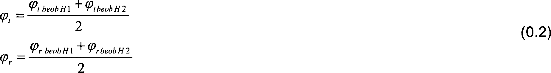
Der
Seilwinkel in tangentiale Richtung φt berechnet
sich also aus dem Mittelwert der beobachteten Winkelsignale der
Halterung
In dem betrachteten Fall ist die Dynamik der Auslegerbewegung durch einige vorherrschende nichtlineare Wirkungen gekennzeichnet. Die Verwendung eines linearen Steuergerät würde daher große Fehler bei der Trajektoriennachführung und ungenügende Dämpfung der Lastpendelung bewirken. Um diese Probleme zu überwinden, nutzt die vorliegende Erfindung ein nichtlineares Steuerungsvorgehen, das auf der Umkehr eines vereinfachten nichtlinearen Modells beruht. Dieses Steuerungsvorgehen für die Wippbewegung eines Auslegerkrans erlaubt eine schwenkfreie Lastbewegung in radialer Richtung. Durch Verwenden einer zusätzlichen stabilisierenden Regelungsschleife zeigt die sich ergebende erfindungsgemäße Kransteuerung eine hohe Genauigkeit der Trajektoriennachführung und eine gute Dämpfung der Lastpendelung. Messergebnisse werden vorgelegt, um die gute Leistung des nichtlinearen Trajektoriennachführungssteuergeräts zu validieren.In the case considered, the dynamics of boom movement is characterized by some predominant non-linear effects. The use of a linear controller would therefore cause large errors in trajectory tracking and inadequate damping of the load swing. To overcome these problems, the present invention utilizes a non-linear control approach based on the reversal of a simplified nonlinear model. This control procedure for the rocking movement of a jib crane allows a swing-free load movement in the radial direction. By using an additional stabilizing control loop, the resulting crane control according to the invention shows a high accuracy trajectory tracking and good damping of load oscillation. Measurement results are presented to validate the good performance of the nonlinear trajectory tracking controller.
Auslegerkrane
wie der LIEBHERR Hafenmobilkran LHM (siehe
Wie
in
Im Allgemeinen sind Krane unteraktuierte Systeme, die Schwingverhalten zeigen. Daher wurden in der Literatur viele ungeregelte und geregelte Steuerlösungen vorgeschlagen. Diese Ansätze beruhen aber auf dem linearisierten dynamischen Modell des Krans. Die meisten dieser Beiträge berücksichtigen nicht die Aktordynamik und -kinematik. Bei einem Auslegerkran, der durch Hydraulikaktoren angetrieben wird, sind die Dynamik und Kinematik der Hydraulikaktoren nicht vernachlässigbar. Insbesondere bei dem Auslegeraktor (Hydraulikzylinder) muss die Kinematik berücksichtigt werden.in the Generally, cranes are under-actuated systems, the vibration behavior demonstrate. Therefore, many unregulated and regulated in the literature Tax solutions proposed. These approaches are based but on the linearized dynamic model of the crane. Most these contributions do not consider the actor dynamics and kinematics. For a jib crane powered by hydraulic actuators is driven, are the dynamics and kinematics of the hydraulic actuators not negligible. Especially with the boom actuator (Hydraulic cylinder), the kinematics must be considered.
Die folgende Ausführung der vorliegenden Erfindung nutzt einen auf Flachheit basierenden Steuerungsansatz für die radiale Richtung eines Auslegerkrans. Der An satz beruht auf einem vereinfachten nichtlinearen Modell des Krans. Somit kann das Gesetz der linearisierenden Steuerung formuliert werden. Ferner wird gezeigt, dass die Nulldynamik der nicht vereinfachten nichtlinearen Steuerschleife eine ausreichende Dämpfungseigenschaft garantiert.The The following embodiment of the present invention uses a Flatness-based control approach for the radial Direction of a jib crane. The approach is based on a simplified non-linear model of the crane. Thus, the law of linearizing Control formulated. Furthermore, it is shown that the zero dynamics the non-simplified non-linear control loop sufficient damping property guaranteed.
1. NICHTLINEARES MODELL DES KRANS1. NONLINEAR MODEL OF THE CRANE
Unter Berücksichtigen der Steuerungsziele der Verhinderung der Lastpendelung und des Nachverfolgens einer Bezugstrajektorie in radialer Richtung muss das nichtlineare dynamische Modell für die Wippbewegung abgeleitet werden. Der erste Teil des Modells wird erhalten durch
- • Vernachlässigen der Masse und der Elastizität des Seils
- • Annahme, dass Last eine Punktmasse ist
- • Vernachlässigen der Zentripetal- und Coriolis-Terme
- • Neglecting the mass and elasticity of the rope
- • Assume that load is a point mass
- • Neglecting the centripetal and Coriolis terms
Das
Verwenden des Newton/Eulerschen Verfahrens und das Berücksichtigen
der vorgegebenen Annahmen führt zu der folgenden Differentialgleichung
der Bewegung für die Lastpendelung in radialer Richtung: ![]()
![]()
Der zweite Teil des dynamischen Modells beschreibt die Kinematik und Dynamik des Aktors für die radiale Richtung. Unter der Annahme, dass der Hydraulikzylinder Verhalten erster Ordnung aufweist, wird die Differentialgleichung der Bewegung wie folgt erhalten:Of the second part of the dynamic model describes the kinematics and Dynamics of the actuator for the radial direction. Under the Assuming that the hydraulic cylinder has first order behavior, the differential equation of motion is obtained as follows:
![]()
![]()
Wobei z ..zyl und z .zyl die Zylinderbeschleunigung und Geschwindigkeit, Tw die Zeitkonstante, Azyl die Querschnittfläche des Zylinders, uw die Eingangsspannung des Servoventils und KVW die proportionale Konstante von Strömrate zu uW ist.Where z .. zyl and z. cyl is the cylinder acceleration and velocity, T w is the time constant, A zyl is the cross-sectional area of the cylinder, u w is the input voltage of the servo valve, and K VW is the proportional constant of flow rate to u W.
![]()
![]()
![]()
![]()
Das Formulieren des Verhaltens erster Ordnung des Aktors in Ausladungskoordinaten durch Verwenden der Gleichungen (4) führt zu einer nichtlinearen Differentialgleichung.The Formulating the behavior of the first order of the actuator in Ausladungskoordinaten by using equations (4) results in a nonlinear Differential equation.
![]()
![]()
Zum
Darstellen des nichtlinearen Modells in der Form ![]()
![]()
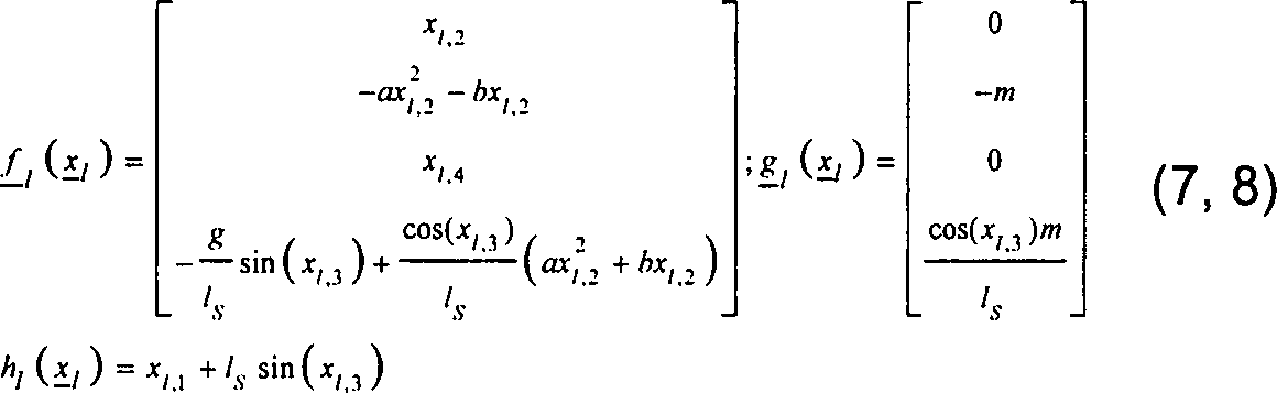
![]()
![]()
2. NICHT-LINEARER STEUERUNGSANSATZ2. Non-linear control approach
Die folgenden Überlegungen werden unter der Annahme getroffen, dass die rechte Seite der Differentialgleichung für die Lastpendelung linearisiert werden kann. Somit wird die Erregung des radialen Lastpendelung von dem radialen Seilwinkel φSr entkoppelt.The following considerations are made on the assumption that the right side of the differential equation for the load swing can be linearized. Thus, the excitation of the radial load oscillation is decoupled from the radial rope angle φ Sr.
![]()
![]()
Um eine flache Ausgabe für das vereinfachte nichtlineare System zu finden, muss der relative Grad bestimmt werden.Around a flat output for the simplified non-linear system to find the relative degree must be determined.
2.1 Relativer Grad2.1 Relative degree
Der
relative Grad wird durch die folgenden Bedingungen definiert: ![]()
![]()
Der
Operator ![]()
![]()
![]()
![]()
![]()
![]()
![]()
![]()
![]()
![]()
2.2 Exakte Linearisierung2.2 Exact Linearization
Da
die vereinfachte Systemdarstellung differentiell flach ist, kann
eine exakte Linearisierung vorgenommen werden. Daher wird eine neue
Eingabe definiert als ![]()
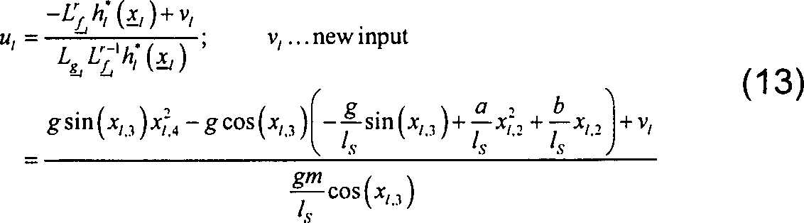
![]()
Um das sich ergebende linearisierte System zu stabilisieren, wird eine Fehlerrückführung zwischen der Bezugstrajektorie und den Ableitungen der Ausgabe y* abgeleitet.In order to stabilize the resulting linearized system, error feedback is derived between the reference trajectory and the derivatives of the output y * .
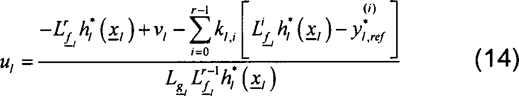
Die
Rückführungsverstärkungen kl,i werden
durch die Polplatzierungstechnik erhalten.
Das
Nachführungssteuergerät beruht auf der vereinfachten
Lastpendelung ODE (8) und nicht auf der Lastpendelung ODE (1). Ferner
wird für die Steuergerätauslegung die fiktive
Ausgabe
3. Bahnplanung/Trajektoriengenerierung3. Path planning / trajectory generation
A. Formulierung des OptimalsteuerungsproblemsA. Formulation of the optimal control problem
Das
Problem der Trajektoriengenerierung wird als beschränktes
Optimalsteuerungsproblem der offenen Kette für das linearisierte
System mit Zustandsrückführung formuliert. Aufgrund
der relevanten Berechnungszeit für die Lösung
des Optimalsteuerungsproblems wird die Modellprädiktive
Trajektoriengenerierung mit einer nicht zu vernachlässigbaren
Abtastzeit ausgeführt. Ebenfalls wird durch das numerische
Lösungsverfahren selbst eine Diskretisierung der Zeitachse
eingeführt. Der Einfachheit halber wird allerdings das
Optimalsteuerungsproblem fortlaufend in kontinuierlicher Zeit dargestellt.
Die Modellgleichungen sind gegeben durch:
Die Zustandvariablen xlin sind die Zustände der Integratorkette, welche sich aus dem linearisierten System, bestehend aus Flachheitsbasiertem Regler (Gleichung (14)) und nichtlinearem System (Gleichung (6)), ergibt, und den Zuständen der Integratorkette für die Referenztrajektorie. Zusätzliche Zustände werden eingeführt, um einen glatten Eingang ν zu erhalten. Der Anfangszustand xlin,0 wird aus den Zuständen dieser Integratoren, dem aktuellen Systemausgang und dessen Ableitungen hergeleitet. Die Ausgänge ylin des linearen Systems (Gleichung (15)) sind Variablen, die dem flachen Ausgang y* (Gleichung (12)) und dessen erste und zweite Ableitung entsprechen. Diese Variablen sind die Position, Geschwindigkeit und Beschleunigung der Last in radialer Richtung.The state variables x lin are the states of the integrator chain resulting from the linearized system consisting of flatness-based controller (equation (14)) and nonlinear system (equation (6)) and the states of the integrator chain for the reference trajectory. Additional states are introduced to get a smooth input ν. The initial state x lin, 0 is derived from the states of these integrators, the current system output and its derivatives. The outputs y lin of the linear system (Equation (15)) are variables corresponding to the shallow output y * (Equation (12)) and its first and second derivatives. These variables are the position, velocity and acceleration of the load in the radial direction.
Das
Gütefunktional ![]()
![]()
Der Optimierungshorizont tf – t0 sollte das wesentliche dynamische Verhalten des Prozesses/Systems erfassen. Dieses ist definiert durch die Periodendauer des Lastpendelns (bis 18 Sekunden für den betrachteten Kran). Versuche zeigen, dass 10 Sekunden für den Optimierungshorizont ausreichen.The optimization horizon t f - t 0 should capture the essential dynamic behavior of the process / system. This is defined by the period of load swinging (up to 18 seconds for the crane under consideration). Experiments show that 10 seconds are sufficient for the optimization horizon.
Die Referenzprognose w(t) für die Lastposition, -geschwindigkeit und -beschleunigung wird aus den Handhebelsignalen des Kranfahrers (Sollgeschwindigkeiten) generiert. Die Prädiktion berücksichtigt Geschwindigkeitsreduzierungen, wenn sich die Last den Grenzen des Arbeitsbereiches nähert.The Reference prognosis w (t) for the load position, speed and acceleration becomes out of the hand lever signals of the crane operator (Target speeds) generated. The prediction takes into account Speed reductions when the load is beyond the limits of Workspace approaches.
Die
Modellprädiktive Trajektoriengenerierung berücksichtigt
Restriktionen für die Prozessvariablen als Beschränkungen
des Optimalsteuerungsproblems.
Beschränkungen
der Änderung des Eingangs werden verwendet, um hochfrequente
Anregungen des Systems zu vermeiden.
Damit müssen die Änderungsraten u .lin als Stellgrößen bei der Formulierung des Optimalsteuerungsproblems berücksichtigt werden.Thus, the change rates u. lin are considered as manipulated variables in the formulation of the optimal control problem.
Die
Generierung der Referenztrajektorien führt zu einem äußeren
Regelkreis (
Beschränkungen
von diesem Typ (Gleichung (19)) verursachen wahrscheinlich unlösbare
Optimalsteuerungsprobleme unter nicht nominalen Bedingungen, wie
Modellunsicherheiten oder Messrauschen, besonders für kurze
Optimierungshorizonte. Somit wird die Gleichungsbeschränkung
(19) als quadratischer Strafterm mit symmetrischer, positiv definiter
Wichtungsmatrix
B. Numerische Lösung des OptimalsteuerungsproblemsB. Numerical solution of the optimal control problem
Das
zeitkontinuierliche, beschränkte, linear-quadratische Optimalsteuerungsproblem
(15)–(20) wird diskretisiert.
Wobei x k / lin, uk and y k / lin die Werte der entsprechenden Variablen in den Diskretisierungpunkten tk bezeichnen. Die Matrizen und Vektoren Ak, bk and Ck erhält man durch Lösen der Transitionsgleichung in [tk, tk+1] aus A, b und C.Where x k / lin, u k and y k / lin the values of the corresponding variables in the Diskretisierungpunkten t k Marked NEN. The matrices and vectors A k , b k, and C k are obtained by solving the transition equation in [t k , t k + 1 ] from A, b, and C.
Das Gütefunktional (Gleichung (20)) und die Beschränkungen (Gleichungen (17) (18)) werden ebenfalls entsprechend diskretisiert.The Quality functional (equation (20)) and the limitations (Equations (17) (18)) are also discretized accordingly.
Damit wird das zeitkontinuierliche Optimalsteuerungsproblem als eine Aufgabe der quadratischen Programmierung für die Zustandvariablen und Stellgrößen [x k / lin, u k / lin] des diskreten Problems approximiert und kann mit einem üblichen „Interior Point" Algorithmus gelöst werden. In dem Algorithmus wird die Struktur der diskreten Modellgleichungen in einem RICCATI-ähnlichen Ansatz genutzt, um eine Lösung der NEWTONschritt-Gleichung mit O(K(m3 + n3)) Operationen zu erhalten. D. h. der Berechnungsaufwand steigt linear mit dem Optimierungshorizont K und kubisch mit der Anzahl der Stellgrößen(m) und Zustandsvariablen(n).Thus, the continuous-time optimal control problem is approximated as a task of quadratic programming for the state variables and manipulated variables [xk / lin, uk / lin] of the discrete problem and can be solved by a conventional "interior point" algorithm Model equations are used in a RICCATI-like approach to obtain a solution of the NEWTON step equation with O (K (m 3 + n 3 )) operations, ie the computational effort increases linearly with the optimization horizon K and cubic with the number of Manipulated variables (m) and state variables (n).
Nicht äquidistante Diskretisierungsschritte ΔTk = tk+1 – tk im Prädiktionshorizont des MPC's helfen die Dimension des Optimalsteuerungsproblems zu begrenzen. Die Darstellung zeigt, dass die Anfangschrittweite durch den Takt der Trajektoriengenerierung bestimmt wird und sich dann innerhalb des Prädiktionshorizontes linear vergrößert.Non-equidistant discretization steps ΔT k = t k + 1 -t k in the MPC's prediction horizon help to narrow the dimension of the optimal control problem. The illustration shows that the initial step size is determined by the timing of the trajectory generation and then increases linearly within the prediction horizon.
Durch die erfindungsgemäße Kransteuerung mit der entsprechenden Lastpendeldämpfung, in welche Daten von den beiden den jeweiligen Seilsträngen zugeordneten Sensoreinheiten eingehen und welche wie oben beschrieben aufgebaut ist, lässt sich eine schnelle und sichere Dämpfung der sphärischen Pendelschwingungen der Last mit nur minimalen Pendelausschlägen erreichen. Dies zeigen die folgenden Messergebnisse, welche mit einer Seillänge von 57 m und einer Last von 3,5 t durchgeführt wurden.By the crane control according to the invention with the corresponding Load swing damping, in which data from the two respective sensor units assigned to respective cable strands and which is constructed as described above can be a fast and safe damping of the spherical Pendulum vibration of the load with only minimal pendulum deflection to reach. This is shown by the following measurement results, which with a rope length of 57 m and a load of 3.5 t performed were.
Die
erfindungsgemäße Regelung dämpft die
sphärischen Schwingungen der Last durch entsprechende kompensierende
Bewegungen des Auslegers während und am Ende jedes Manövers.
Dies ist in
Die
für die Online-Berechnung des Optimallösungsproblems
in dem Bahnplanungsmodul benötigte Rechenzeit ist dabei
in
ZITATE ENTHALTEN IN DER BESCHREIBUNGQUOTES INCLUDE IN THE DESCRIPTION
Diese Liste der vom Anmelder aufgeführten Dokumente wurde automatisiert erzeugt und ist ausschließlich zur besseren Information des Lesers aufgenommen. Die Liste ist nicht Bestandteil der deutschen Patent- bzw. Gebrauchsmusteranmeldung. Das DPMA übernimmt keinerlei Haftung für etwaige Fehler oder Auslassungen.This list The documents listed by the applicant have been automated generated and is solely for better information recorded by the reader. The list is not part of the German Patent or utility model application. The DPMA takes over no liability for any errors or omissions.
Zitierte PatentliteraturCited patent literature
- - DE 10064182 [0002, 0112] - DE 10064182 [0002, 0112]
- - DE 10324692 [0002, 0112] - DE 10324692 [0002, 0112]
- - DE 10029579 [0003, 0112] - DE 10029579 [0003, 0112]
- - DE 102006033277 [0003, 0112] - DE 102006033277 [0003, 0112]
- - DE 102006048988 [0173] - DE 102006048988 [0173]
Claims (61)
Priority Applications (7)
| Application Number | Priority Date | Filing Date | Title |
|---|---|---|---|
| DE102007039408A DE102007039408A1 (en) | 2007-05-16 | 2007-08-21 | Crane control system for crane with cable for load lifting by controlling signal tower of crane, has sensor unit for determining cable angle relative to gravitational force |
| ES08008276T ES2531374T5 (en) | 2007-05-16 | 2008-04-30 | Crane with crane control |
| EP12004726.1A EP2502871B1 (en) | 2007-05-16 | 2008-04-30 | Crane control, crane and method |
| DE202008018260U DE202008018260U1 (en) | 2007-05-16 | 2008-04-30 | Crane control and crane |
| ES12004726.1T ES2527739T3 (en) | 2007-05-16 | 2008-04-30 | Crane, crane and procedure control |
| EP08008276.1A EP1992583B2 (en) | 2007-05-16 | 2008-04-30 | Crane control, crane and method |
| US12/152,717 US8025167B2 (en) | 2007-05-16 | 2008-05-16 | Crane control, crane and method |
Applications Claiming Priority (3)
| Application Number | Priority Date | Filing Date | Title |
|---|---|---|---|
| DE102007023027 | 2007-05-16 | ||
| DE102007023027.5 | 2007-05-16 | ||
| DE102007039408A DE102007039408A1 (en) | 2007-05-16 | 2007-08-21 | Crane control system for crane with cable for load lifting by controlling signal tower of crane, has sensor unit for determining cable angle relative to gravitational force |
Publications (1)
| Publication Number | Publication Date |
|---|---|
| DE102007039408A1 true DE102007039408A1 (en) | 2008-11-20 |
Family
ID=39868919
Family Applications (2)
| Application Number | Title | Priority Date | Filing Date |
|---|---|---|---|
| DE102007039408A Withdrawn DE102007039408A1 (en) | 2007-05-16 | 2007-08-21 | Crane control system for crane with cable for load lifting by controlling signal tower of crane, has sensor unit for determining cable angle relative to gravitational force |
| DE202008018260U Expired - Lifetime DE202008018260U1 (en) | 2007-05-16 | 2008-04-30 | Crane control and crane |
Family Applications After (1)
| Application Number | Title | Priority Date | Filing Date |
|---|---|---|---|
| DE202008018260U Expired - Lifetime DE202008018260U1 (en) | 2007-05-16 | 2008-04-30 | Crane control and crane |
Country Status (4)
| Country | Link |
|---|---|
| US (1) | US8025167B2 (en) |
| EP (1) | EP2502871B1 (en) |
| DE (2) | DE102007039408A1 (en) |
| ES (2) | ES2527739T3 (en) |
Cited By (11)
| Publication number | Priority date | Publication date | Assignee | Title |
|---|---|---|---|---|
| EP2272786A1 (en) * | 2009-07-08 | 2011-01-12 | Liebherr-Werk Nenzing GmbH | Crane control for controlling a crane's hoisting gear |
| DE102009032270A1 (en) * | 2009-07-08 | 2011-01-13 | Liebherr-Werk Nenzing Gmbh | Method for controlling a drive of a crane |
| DE102010027771A1 (en) * | 2010-04-15 | 2011-10-20 | Airbus Operations Gmbh | Device for controlling e.g. civilian airliner, has calculation unit for computing guide signal, where points of discontinuity are determined such that approximation of signal takes place in subspaces lying between points of discontinuity |
| DE102013219279A1 (en) | 2013-09-25 | 2015-03-26 | Schaeffler Technologies Gmbh & Co. Kg | Load-bearing damper and lifting device for suspended loads |
| WO2016019289A1 (en) * | 2014-07-31 | 2016-02-04 | Par Systems, Inc. | Crane motion control |
| EP2272784B1 (en) * | 2009-07-08 | 2017-03-22 | Liebherr-Werk Nenzing GmbH | Crane for covering a load suspended on a load rope |
| CN110406531A (en) * | 2018-04-25 | 2019-11-05 | 株式会社万都 | Collision prevention of vehicle control device and its control method |
| DE202019102393U1 (en) | 2019-03-08 | 2020-06-09 | Liebherr-Werk Biberach Gmbh | Crane and device for its control |
| CN113086862A (en) * | 2021-04-09 | 2021-07-09 | 国网山东省电力公司安丘市供电公司 | Electric element conveyor |
| US11174134B2 (en) | 2016-11-09 | 2021-11-16 | Liebherr-Werk Biberach Gmbh | Apparatus for compensating diagonal pull in cranes |
| DE102023109701A1 (en) * | 2023-04-18 | 2024-10-24 | Liebherr-Werk Nenzing Gmbh | Method, system and computer program product for moving a load by means of a plurality of cranes |
Families Citing this family (81)
| Publication number | Priority date | Publication date | Assignee | Title |
|---|---|---|---|---|
| US7467614B2 (en) | 2004-12-29 | 2008-12-23 | Honeywell International Inc. | Pedal position and/or pedal change rate for use in control of an engine |
| US7389773B2 (en) | 2005-08-18 | 2008-06-24 | Honeywell International Inc. | Emissions sensors for fuel control in engines |
| DE102008024513B4 (en) * | 2008-05-21 | 2017-08-24 | Liebherr-Werk Nenzing Gmbh | Crane control with active coast sequence |
| US8060290B2 (en) | 2008-07-17 | 2011-11-15 | Honeywell International Inc. | Configurable automotive controller |
| US8195368B1 (en) * | 2008-11-07 | 2012-06-05 | The United States Of America As Represented By The Secretary Of The Navy | Coordinated control of two shipboard cranes for cargo transfer with ship motion compensation |
| FR2939783B1 (en) * | 2008-12-15 | 2013-02-15 | Schneider Toshiba Inverter | DEVICE FOR CONTROLLING THE DISPLACEMENT OF A LOAD SUSPENDED TO A CRANE |
| CN101659379B (en) * | 2009-08-27 | 2012-02-08 | 三一汽车制造有限公司 | Method, system and device for controlling deviation of hanging hook |
| US8620461B2 (en) | 2009-09-24 | 2013-12-31 | Honeywell International, Inc. | Method and system for updating tuning parameters of a controller |
| US8504175B2 (en) | 2010-06-02 | 2013-08-06 | Honeywell International Inc. | Using model predictive control to optimize variable trajectories and system control |
| CA2834234C (en) | 2011-04-29 | 2017-05-09 | Harnischfeger Technologies, Inc. | Controlling a digging operation of an industrial machine |
| CN102249151B (en) * | 2011-05-20 | 2013-06-12 | 林汉丁 | Laser display and supervision arrangement for declination angle of crane lift hook |
| WO2013006625A2 (en) | 2011-07-05 | 2013-01-10 | Trimble Navigation Limited | Crane maneuvering assistance |
| DE102011108284A1 (en) * | 2011-07-21 | 2013-01-24 | Liebherr-Werk Ehingen Gmbh | Crane control and crane |
| ES2447018T3 (en) * | 2011-08-26 | 2014-03-11 | Liebherr-Werk Nenzing Gmbh | Crane control device |
| US9677493B2 (en) | 2011-09-19 | 2017-06-13 | Honeywell Spol, S.R.O. | Coordinated engine and emissions control system |
| US20130111905A1 (en) | 2011-11-04 | 2013-05-09 | Honeywell Spol. S.R.O. | Integrated optimization and control of an engine and aftertreatment system |
| US9650934B2 (en) | 2011-11-04 | 2017-05-16 | Honeywell spol.s.r.o. | Engine and aftertreatment optimization system |
| CN102431897B (en) * | 2011-11-25 | 2014-04-30 | 林汉丁 | Crane lifting verticality deviation measuring and displaying device and lifting method |
| DE102012004802A1 (en) * | 2012-03-09 | 2013-09-12 | Liebherr-Werk Nenzing Gmbh | Crane control with distribution of a kinematically limited size of the hoist |
| DE102012004914A1 (en) * | 2012-03-09 | 2013-09-12 | Liebherr-Werk Nenzing Gmbh | Crane control with rope power mode |
| CN102910533A (en) * | 2012-10-26 | 2013-02-06 | 北京机械设备研究所 | Spatial angle measuring method based on crane |
| FI20135085L (en) * | 2013-01-29 | 2014-07-30 | John Deere Forestry Oy | Method and system for controlling the boom of a work machine with tip control |
| EP2821359B1 (en) * | 2013-07-05 | 2018-04-04 | Liebherr-Werk Nenzing GmbH | Crane controller |
| DE102013012019B4 (en) | 2013-07-19 | 2019-10-24 | Tadano Faun Gmbh | Crane, in particular mobile crane |
| ES2534957B1 (en) * | 2013-09-30 | 2016-02-02 | Yoel Orlando IZQUIERDO HERNÁNDEZ | SYSTEM FOR REPORTING THE CRANK OF LIFTING CRANES AND APPLIANCES WITH RESPECT TO LOAD. |
| DE102014008094A1 (en) | 2014-06-02 | 2015-12-03 | Liebherr-Werk Nenzing Gmbh | Method for controlling the alignment of a crane load and a jib crane |
| CN104340875B (en) * | 2014-10-09 | 2016-05-11 | 中联重科股份有限公司 | Crane boom posture monitoring control system, method and device and crane |
| EP3051367B1 (en) | 2015-01-28 | 2020-11-25 | Honeywell spol s.r.o. | An approach and system for handling constraints for measured disturbances with uncertain preview |
| EP3056464A1 (en) * | 2015-02-11 | 2016-08-17 | Siemens Aktiengesellschaft | Automated crane control taking into account load and location dependent measurement errors |
| EP3056706A1 (en) | 2015-02-16 | 2016-08-17 | Honeywell International Inc. | An approach for aftertreatment system modeling and model identification |
| US20160244302A1 (en) * | 2015-02-23 | 2016-08-25 | Transocean Sedco Forex Ventures Limited | Marine motion compensated draw-works real-time performance monitoring and prediction |
| EP3091212A1 (en) | 2015-05-06 | 2016-11-09 | Honeywell International Inc. | An identification approach for internal combustion engine mean value models |
| EP3734375B1 (en) | 2015-07-31 | 2023-04-05 | Garrett Transportation I Inc. | Quadratic program solver for mpc using variable ordering |
| US10272779B2 (en) | 2015-08-05 | 2019-04-30 | Garrett Transportation I Inc. | System and approach for dynamic vehicle speed optimization |
| WO2017059493A1 (en) * | 2015-10-08 | 2017-04-13 | Verton Technologies Australia Pty Ltd | Materials management systems and methods |
| PL3362400T3 (en) * | 2015-10-16 | 2020-03-31 | Palfinger Ag | Arrangement of a control device and a mobile control module |
| US10415492B2 (en) | 2016-01-29 | 2019-09-17 | Garrett Transportation I Inc. | Engine system with inferential sensor |
| DE102016001684A1 (en) * | 2016-02-12 | 2017-08-17 | Liebherr-Werk Biberach Gmbh | Method for monitoring at least one crane |
| DE102016004266A1 (en) | 2016-04-08 | 2017-10-12 | Liebherr-Werk Biberach Gmbh | Construction machine, in particular crane, and method for its control |
| DE102016004249A1 (en) | 2016-04-08 | 2017-10-12 | Liebherr-Components Biberach Gmbh | crane |
| DE102016004350A1 (en) | 2016-04-11 | 2017-10-12 | Liebherr-Components Biberach Gmbh | Crane and method for controlling such a crane |
| US10036338B2 (en) | 2016-04-26 | 2018-07-31 | Honeywell International Inc. | Condition-based powertrain control system |
| US10124750B2 (en) | 2016-04-26 | 2018-11-13 | Honeywell International Inc. | Vehicle security module system |
| CN106185627B (en) * | 2016-07-06 | 2020-09-08 | 林汉丁 | Lifting hook deflection angle monitoring device, vertical hoisting monitoring device and mobile crane |
| DE202016008626U1 (en) * | 2016-11-15 | 2018-09-14 | Josef Morosin | Arrangement with a crane |
| EP3548729B1 (en) | 2016-11-29 | 2023-02-22 | Garrett Transportation I Inc. | An inferential flow sensor |
| US11111115B2 (en) | 2017-03-02 | 2021-09-07 | Maniitowoc Crane Companies, LLC | Wear pad with insert for telescoping boom assembly |
| DE102017114789A1 (en) * | 2017-07-03 | 2019-01-03 | Liebherr-Components Biberach Gmbh | Crane and method for controlling such a crane |
| FR3071489A1 (en) * | 2017-09-28 | 2019-03-29 | Manitowoc Crane Group France | METHOD FOR SECURING A CRANE ARROW CRANE AND ASSOCIATED CRANE |
| EP3461783B1 (en) * | 2017-09-29 | 2019-11-13 | B&R Industrial Automation GmbH | Lifting device and method for controlling a lifting device |
| US11057213B2 (en) | 2017-10-13 | 2021-07-06 | Garrett Transportation I, Inc. | Authentication system for electronic control unit on a bus |
| US10828790B2 (en) * | 2017-11-16 | 2020-11-10 | Google Llc | Component feature detector for robotic systems |
| NL2021043B1 (en) * | 2018-06-01 | 2019-12-10 | Itrec Bv | Offshore wind turbine installation vessel and a crane for providing such a vessel and method for upending a monopile |
| US10654692B2 (en) * | 2018-05-04 | 2020-05-19 | Rowan Companies, Inc. | System and method for remote crane operations on offshore unit |
| EP3566998B1 (en) * | 2018-05-11 | 2023-08-23 | ABB Schweiz AG | Control of overhead cranes |
| DE102018005068A1 (en) | 2018-06-26 | 2020-01-02 | Liebherr-Components Biberach Gmbh | Crane and method for controlling such a crane |
| JP7172243B2 (en) * | 2018-07-25 | 2022-11-16 | 株式会社タダノ | Cranes and crane control systems |
| US12358763B2 (en) | 2018-11-07 | 2025-07-15 | Manitowoc Crane Companies, Llc | System for determining crane status using optical and/or electromagnetic sensors |
| JP7134087B2 (en) * | 2018-12-27 | 2022-09-09 | コベルコ建機株式会社 | Load deflection angle measuring device for cranes |
| JP7322901B2 (en) * | 2019-02-14 | 2023-08-08 | 株式会社タダノ | Ground-breaking control device and mobile crane |
| EP3925918A4 (en) * | 2019-02-14 | 2022-11-23 | Tadano Ltd. | DYNAMIC TAKE-OFF CONTROL DEVICE AND CRANE |
| JP7151532B2 (en) * | 2019-02-14 | 2022-10-12 | 株式会社タダノ | Crane and crane path generation system |
| JP7247703B2 (en) * | 2019-03-27 | 2023-03-29 | 株式会社タダノ | Crane control method and crane |
| DE102019109448B4 (en) | 2019-04-10 | 2022-09-08 | Josef Morosin | Arrangement with a crane |
| US11618566B1 (en) * | 2019-04-12 | 2023-04-04 | Vita Inclinata Technologies, Inc. | State information and telemetry for suspended load control equipment apparatus, system, and method |
| US11834305B1 (en) * | 2019-04-12 | 2023-12-05 | Vita Inclinata Ip Holdings Llc | Apparatus, system, and method to control torque or lateral thrust applied to a load suspended on a suspension cable |
| CN112079252A (en) * | 2019-06-14 | 2020-12-15 | 湖南釜晟智能科技有限责任公司 | Anti-swing control system for overhead travelling crane hoisted object |
| DE102019122796A1 (en) | 2019-08-26 | 2021-03-04 | Liebherr-Werk Biberach Gmbh | Crane and method of controlling such a crane |
| DE102020112227A1 (en) * | 2019-11-22 | 2021-05-27 | Liebherr-Werk Biberach Gmbh | Construction and / or material handling machine |
| US12099337B1 (en) * | 2019-12-06 | 2024-09-24 | Vita Inclinata Ip Holdings Llc | Control moment gyroscope hoist stabilization system, method, and apparatus |
| CN111348544A (en) * | 2020-04-16 | 2020-06-30 | 林汉丁 | Real-time lifting hook deflection angle monitoring device capable of displaying lifting weight and crane |
| JP7445510B2 (en) * | 2020-05-01 | 2024-03-07 | 株式会社Ihi | Shake angle detection device |
| CN111573504A (en) * | 2020-05-20 | 2020-08-25 | 林汉丁 | A single-machine hoisting and hoisting synergistic hoisting device and mobile crane |
| DE102020120699A1 (en) * | 2020-08-05 | 2022-02-10 | Konecranes Global Corporation | Slewing jib crane with a camera and methods for reducing load sway during crane operation |
| DE102020126504A1 (en) | 2020-10-09 | 2022-04-14 | Liebherr-Werk Biberach Gmbh | Hoist such as a crane and method and device for controlling such a hoist |
| CN112324793B (en) * | 2020-11-20 | 2021-12-24 | 安徽博微长安电子有限公司 | Telescopic wind-resistant pull rod mechanism |
| USD1019048S1 (en) * | 2021-07-01 | 2024-03-19 | Liebherr-Werk Biberach Gmbh | Crane |
| CN113465567B (en) * | 2021-08-11 | 2022-05-31 | 广东皓耘科技有限公司 | Cable parameter detection device and cable parameter detection method |
| DE102021130785A1 (en) | 2021-11-24 | 2023-05-25 | Liebherr-Werk Biberach Gmbh | crane |
| CN115291527B (en) * | 2022-09-30 | 2022-12-20 | 成都航天万欣科技有限公司 | Follow-up control method, system, equipment and storage medium |
| DE102023109735A1 (en) * | 2023-04-18 | 2024-10-24 | Liebherr-MCCtec Rostock GmbH | crane |
Citations (11)
| Publication number | Priority date | Publication date | Assignee | Title |
|---|---|---|---|---|
| DD275035A1 (en) * | 1988-08-29 | 1990-01-10 | Univ Dresden Tech | DEVICE FOR MEASURING THE PENDULUM ANGLE |
| JPH04223993A (en) * | 1990-09-21 | 1992-08-13 | Kobe Steel Ltd | Rope swinging angle detecting device of crane |
| DE4032332C2 (en) * | 1990-10-09 | 1994-01-20 | Mannesmann Ag | Measuring device for detecting the pendulum angle |
| DE19842436A1 (en) * | 1998-09-16 | 2000-03-30 | Grove Us Llc Shady Grove | Method and device for compensating for the deformation of a crane boom when lifting and lowering loads |
| DE10029579A1 (en) | 2000-06-15 | 2002-01-03 | Hofer Eberhard | Method for orientating a load in crane equipment uses slewing gear between a cable and a load to rotate the load suspended on cables at a defined absolute angle. |
| DE10042699A1 (en) * | 2000-08-31 | 2002-04-04 | Elektroschaltanlagen Gmbh | Crane load swing angle sensor uses inclinometer is cheap allows good control |
| DE10064182A1 (en) | 2000-10-19 | 2002-05-08 | Liebherr Werk Nenzing | Crane or excavator for handling a load suspended from a load rope with load swing damping |
| DE10324692A1 (en) | 2003-05-30 | 2005-01-05 | Liebherr-Werk Nenzing Gmbh, Nenzing | Crane or excavator for handling a load suspended on a load rope with optimized motion control |
| EP1326798B1 (en) * | 2000-10-19 | 2006-04-05 | Liebherr-Werk Nenzing GmbH | Crane or digger for swinging a load hanging on a support cable with damping of load oscillations |
| DE102006033277A1 (en) | 2006-07-18 | 2008-02-07 | Liebherr-Werk Nenzing Gmbh, Nenzing | Method for controlling the orientation of a crane load |
| DE102006048988A1 (en) | 2006-10-17 | 2008-04-24 | Liebherr-Werk Nenzing Gmbh, Nenzing | Control system for jib crane, has jib pivotably attached to tower, where acceleration of load in radial direction is counterbalanced based on rotation of tower by rocking motion of jib dependent on rotational speed of tower |
Family Cites Families (10)
| Publication number | Priority date | Publication date | Assignee | Title |
|---|---|---|---|---|
| US3904156A (en) * | 1974-07-11 | 1975-09-09 | Us Army | External load stabilization apparatus |
| FR2445291A1 (en) * | 1978-12-28 | 1980-07-25 | Casteran Jean | Weight suspension from crane jib - uses symmetrical cable system with angles compared with reference plane on weight and automatically electrically corrected |
| US4471877A (en) * | 1982-09-01 | 1984-09-18 | Whitley Charles C | Crane sensor to detect out of plumb lift cable |
| US4932541A (en) * | 1989-04-24 | 1990-06-12 | Calspan Corporation | Stabilized shipboard crane |
| DE4334069A1 (en) * | 1993-06-21 | 1995-04-13 | Zeiss Carl Fa | Balanced tripod |
| US5729339A (en) * | 1993-09-02 | 1998-03-17 | Korea Atomic Energy Research Institute | Swing angle measuring apparatus for swing free operation of crane |
| AU3715100A (en) * | 1999-03-01 | 2000-09-21 | Elliott Technologies | Crane monitoring and data retrieval system and method |
| US6496765B1 (en) * | 2000-06-28 | 2002-12-17 | Sandia Corporation | Control system and method for payload control in mobile platform cranes |
| US6826452B1 (en) * | 2002-03-29 | 2004-11-30 | The Penn State Research Foundation | Cable array robot for material handling |
| US7489098B2 (en) * | 2005-10-05 | 2009-02-10 | Oshkosh Corporation | System for monitoring load and angle for mobile lift device |
-
2007
- 2007-08-21 DE DE102007039408A patent/DE102007039408A1/en not_active Withdrawn
-
2008
- 2008-04-30 EP EP12004726.1A patent/EP2502871B1/en not_active Not-in-force
- 2008-04-30 DE DE202008018260U patent/DE202008018260U1/en not_active Expired - Lifetime
- 2008-04-30 ES ES12004726.1T patent/ES2527739T3/en active Active
- 2008-04-30 ES ES08008276T patent/ES2531374T5/en active Active
- 2008-05-16 US US12/152,717 patent/US8025167B2/en active Active
Patent Citations (11)
| Publication number | Priority date | Publication date | Assignee | Title |
|---|---|---|---|---|
| DD275035A1 (en) * | 1988-08-29 | 1990-01-10 | Univ Dresden Tech | DEVICE FOR MEASURING THE PENDULUM ANGLE |
| JPH04223993A (en) * | 1990-09-21 | 1992-08-13 | Kobe Steel Ltd | Rope swinging angle detecting device of crane |
| DE4032332C2 (en) * | 1990-10-09 | 1994-01-20 | Mannesmann Ag | Measuring device for detecting the pendulum angle |
| DE19842436A1 (en) * | 1998-09-16 | 2000-03-30 | Grove Us Llc Shady Grove | Method and device for compensating for the deformation of a crane boom when lifting and lowering loads |
| DE10029579A1 (en) | 2000-06-15 | 2002-01-03 | Hofer Eberhard | Method for orientating a load in crane equipment uses slewing gear between a cable and a load to rotate the load suspended on cables at a defined absolute angle. |
| DE10042699A1 (en) * | 2000-08-31 | 2002-04-04 | Elektroschaltanlagen Gmbh | Crane load swing angle sensor uses inclinometer is cheap allows good control |
| DE10064182A1 (en) | 2000-10-19 | 2002-05-08 | Liebherr Werk Nenzing | Crane or excavator for handling a load suspended from a load rope with load swing damping |
| EP1326798B1 (en) * | 2000-10-19 | 2006-04-05 | Liebherr-Werk Nenzing GmbH | Crane or digger for swinging a load hanging on a support cable with damping of load oscillations |
| DE10324692A1 (en) | 2003-05-30 | 2005-01-05 | Liebherr-Werk Nenzing Gmbh, Nenzing | Crane or excavator for handling a load suspended on a load rope with optimized motion control |
| DE102006033277A1 (en) | 2006-07-18 | 2008-02-07 | Liebherr-Werk Nenzing Gmbh, Nenzing | Method for controlling the orientation of a crane load |
| DE102006048988A1 (en) | 2006-10-17 | 2008-04-24 | Liebherr-Werk Nenzing Gmbh, Nenzing | Control system for jib crane, has jib pivotably attached to tower, where acceleration of load in radial direction is counterbalanced based on rotation of tower by rocking motion of jib dependent on rotational speed of tower |
Cited By (16)
| Publication number | Priority date | Publication date | Assignee | Title |
|---|---|---|---|---|
| EP2272786A1 (en) * | 2009-07-08 | 2011-01-12 | Liebherr-Werk Nenzing GmbH | Crane control for controlling a crane's hoisting gear |
| DE102009032270A1 (en) * | 2009-07-08 | 2011-01-13 | Liebherr-Werk Nenzing Gmbh | Method for controlling a drive of a crane |
| US8708170B2 (en) | 2009-07-08 | 2014-04-29 | Liebherr-Werk Nenzing Gmbh | Crane control for the control of a hoisting gear of a crane |
| US10046953B2 (en) | 2009-07-08 | 2018-08-14 | Liebherr-Werk Nenzing Gmbh | Methods for controlling a drive of a crane |
| EP2272784B1 (en) * | 2009-07-08 | 2017-03-22 | Liebherr-Werk Nenzing GmbH | Crane for covering a load suspended on a load rope |
| DE102010027771A1 (en) * | 2010-04-15 | 2011-10-20 | Airbus Operations Gmbh | Device for controlling e.g. civilian airliner, has calculation unit for computing guide signal, where points of discontinuity are determined such that approximation of signal takes place in subspaces lying between points of discontinuity |
| DE102010027771B4 (en) * | 2010-04-15 | 2014-05-22 | Airbus Operations Gmbh | Device and method for controlling or regulating a control route |
| DE102013219279A1 (en) | 2013-09-25 | 2015-03-26 | Schaeffler Technologies Gmbh & Co. Kg | Load-bearing damper and lifting device for suspended loads |
| US9776838B2 (en) | 2014-07-31 | 2017-10-03 | Par Systems, Inc. | Crane motion control |
| WO2016019289A1 (en) * | 2014-07-31 | 2016-02-04 | Par Systems, Inc. | Crane motion control |
| US11174134B2 (en) | 2016-11-09 | 2021-11-16 | Liebherr-Werk Biberach Gmbh | Apparatus for compensating diagonal pull in cranes |
| CN110406531A (en) * | 2018-04-25 | 2019-11-05 | 株式会社万都 | Collision prevention of vehicle control device and its control method |
| DE202019102393U1 (en) | 2019-03-08 | 2020-06-09 | Liebherr-Werk Biberach Gmbh | Crane and device for its control |
| WO2020182592A1 (en) | 2019-03-08 | 2020-09-17 | Liebherr-Werk Biberach Gmbh | Crane and device for controlling same |
| CN113086862A (en) * | 2021-04-09 | 2021-07-09 | 国网山东省电力公司安丘市供电公司 | Electric element conveyor |
| DE102023109701A1 (en) * | 2023-04-18 | 2024-10-24 | Liebherr-Werk Nenzing Gmbh | Method, system and computer program product for moving a load by means of a plurality of cranes |
Also Published As
| Publication number | Publication date |
|---|---|
| ES2527739T3 (en) | 2015-01-29 |
| EP2502871B1 (en) | 2014-12-17 |
| ES2531374T5 (en) | 2024-06-13 |
| US20090008351A1 (en) | 2009-01-08 |
| US8025167B2 (en) | 2011-09-27 |
| EP2502871A1 (en) | 2012-09-26 |
| DE202008018260U1 (en) | 2012-05-15 |
| ES2531374T3 (en) | 2015-03-13 |
Similar Documents
| Publication | Publication Date | Title |
|---|---|---|
| EP2502871B1 (en) | Crane control, crane and method | |
| EP1992583B2 (en) | Crane control, crane and method | |
| EP3784616B1 (en) | Crane and method for controlling such a crane | |
| EP3649072B1 (en) | Crane and method for controlling such a crane | |
| EP4013713B1 (en) | Crane and method for controlling such a crane | |
| EP2298687B1 (en) | System for determining the load mass of a load suspended on a lifting rope of a crane | |
| EP2272785B1 (en) | Method for controlling a drive of a crane | |
| EP2272784B1 (en) | Crane for covering a load suspended on a load rope | |
| EP3408208B1 (en) | Crane, and method for controlling such a crane | |
| DE69606974T2 (en) | METHOD AND DEVICE FOR CONTROLLING THE LOAD SUPPORT ELEMENT AND LOAD FROM A CRANE | |
| EP2524892B1 (en) | Crane control | |
| DE102014008094A1 (en) | Method for controlling the alignment of a crane load and a jib crane | |
| EP2878566B1 (en) | Method for influencing a movement of a load lifted by a crane | |
| DE102006048988A1 (en) | Control system for jib crane, has jib pivotably attached to tower, where acceleration of load in radial direction is counterbalanced based on rotation of tower by rocking motion of jib dependent on rotational speed of tower | |
| DE102009032269A1 (en) | Crane control for controlling a hoist of a crane | |
| DE102007041692A1 (en) | Control device for damping oscillations of a cable-guided load | |
| AT520008A1 (en) | Method for damping torsional vibrations of a load-receiving element of a lifting device | |
| DE102015100669A1 (en) | ANTI-PENDULUM CONTROL PROCEDURE WITH ADJUSTABLE SUPPORT FOR THE TRANSPORT OF AN ANCHORED LOAD | |
| DE10029579A1 (en) | Method for orientating a load in crane equipment uses slewing gear between a cable and a load to rotate the load suspended on cables at a defined absolute angle. | |
| EP3428112A1 (en) | Lifting device, in particular a mobile crane or a cable dredger, having a device for monitoring the alignment and depositing process of a boom system and corresponding method | |
| DE202022003151U1 (en) | Tower crane and control unit for operating a tower crane, trolley and trolley chassis | |
| EP2878567A1 (en) | Method for determining at least one pendulum angle of a load lifted by a load transportation device and method for damping the pendular movements of the load |
Legal Events
| Date | Code | Title | Description |
|---|---|---|---|
| OP8 | Request for examination as to paragraph 44 patent law | ||
| R119 | Application deemed withdrawn, or ip right lapsed, due to non-payment of renewal fee |