DE102004055187B4 - Moldings pair for photovoltaic modules - Google Patents
Moldings pair for photovoltaic modules Download PDFInfo
- Publication number
- DE102004055187B4 DE102004055187B4 DE102004055187A DE102004055187A DE102004055187B4 DE 102004055187 B4 DE102004055187 B4 DE 102004055187B4 DE 102004055187 A DE102004055187 A DE 102004055187A DE 102004055187 A DE102004055187 A DE 102004055187A DE 102004055187 B4 DE102004055187 B4 DE 102004055187B4
- Authority
- DE
- Germany
- Prior art keywords
- profile strip
- profile
- base part
- pair
- pair according
- Prior art date
- Legal status (The legal status is an assumption and is not a legal conclusion. Google has not performed a legal analysis and makes no representation as to the accuracy of the status listed.)
- Expired - Fee Related
Links
Classifications
-
- H—ELECTRICITY
- H02—GENERATION; CONVERSION OR DISTRIBUTION OF ELECTRIC POWER
- H02S—GENERATION OF ELECTRIC POWER BY CONVERSION OF INFRARED RADIATION, VISIBLE LIGHT OR ULTRAVIOLET LIGHT, e.g. USING PHOTOVOLTAIC [PV] MODULES
- H02S20/00—Supporting structures for PV modules
-
- F—MECHANICAL ENGINEERING; LIGHTING; HEATING; WEAPONS; BLASTING
- F24—HEATING; RANGES; VENTILATING
- F24S—SOLAR HEAT COLLECTORS; SOLAR HEAT SYSTEMS
- F24S25/00—Arrangement of stationary mountings or supports for solar heat collector modules
- F24S25/20—Peripheral frames for modules
-
- F—MECHANICAL ENGINEERING; LIGHTING; HEATING; WEAPONS; BLASTING
- F24—HEATING; RANGES; VENTILATING
- F24S—SOLAR HEAT COLLECTORS; SOLAR HEAT SYSTEMS
- F24S25/00—Arrangement of stationary mountings or supports for solar heat collector modules
- F24S25/60—Fixation means, e.g. fasteners, specially adapted for supporting solar heat collector modules
- F24S25/61—Fixation means, e.g. fasteners, specially adapted for supporting solar heat collector modules for fixing to the ground or to building structures
-
- F—MECHANICAL ENGINEERING; LIGHTING; HEATING; WEAPONS; BLASTING
- F24—HEATING; RANGES; VENTILATING
- F24S—SOLAR HEAT COLLECTORS; SOLAR HEAT SYSTEMS
- F24S25/00—Arrangement of stationary mountings or supports for solar heat collector modules
- F24S25/60—Fixation means, e.g. fasteners, specially adapted for supporting solar heat collector modules
- F24S25/63—Fixation means, e.g. fasteners, specially adapted for supporting solar heat collector modules for fixing modules or their peripheral frames to supporting elements
- F24S25/632—Side connectors; Base connectors
-
- F—MECHANICAL ENGINEERING; LIGHTING; HEATING; WEAPONS; BLASTING
- F24—HEATING; RANGES; VENTILATING
- F24S—SOLAR HEAT COLLECTORS; SOLAR HEAT SYSTEMS
- F24S25/00—Arrangement of stationary mountings or supports for solar heat collector modules
- F24S25/60—Fixation means, e.g. fasteners, specially adapted for supporting solar heat collector modules
- F24S25/63—Fixation means, e.g. fasteners, specially adapted for supporting solar heat collector modules for fixing modules or their peripheral frames to supporting elements
- F24S25/634—Clamps; Clips
- F24S25/636—Clamps; Clips clamping by screw-threaded elements
-
- F—MECHANICAL ENGINEERING; LIGHTING; HEATING; WEAPONS; BLASTING
- F24—HEATING; RANGES; VENTILATING
- F24S—SOLAR HEAT COLLECTORS; SOLAR HEAT SYSTEMS
- F24S25/00—Arrangement of stationary mountings or supports for solar heat collector modules
- F24S25/60—Fixation means, e.g. fasteners, specially adapted for supporting solar heat collector modules
- F24S25/67—Fixation means, e.g. fasteners, specially adapted for supporting solar heat collector modules for coupling adjacent modules or their peripheral frames
-
- F—MECHANICAL ENGINEERING; LIGHTING; HEATING; WEAPONS; BLASTING
- F24—HEATING; RANGES; VENTILATING
- F24S—SOLAR HEAT COLLECTORS; SOLAR HEAT SYSTEMS
- F24S25/00—Arrangement of stationary mountings or supports for solar heat collector modules
- F24S2025/01—Special support components; Methods of use
- F24S2025/013—Stackable support elements
-
- F—MECHANICAL ENGINEERING; LIGHTING; HEATING; WEAPONS; BLASTING
- F24—HEATING; RANGES; VENTILATING
- F24S—SOLAR HEAT COLLECTORS; SOLAR HEAT SYSTEMS
- F24S25/00—Arrangement of stationary mountings or supports for solar heat collector modules
- F24S2025/01—Special support components; Methods of use
- F24S2025/018—Means for preventing movements, e.g. stops
-
- F—MECHANICAL ENGINEERING; LIGHTING; HEATING; WEAPONS; BLASTING
- F24—HEATING; RANGES; VENTILATING
- F24S—SOLAR HEAT COLLECTORS; SOLAR HEAT SYSTEMS
- F24S25/00—Arrangement of stationary mountings or supports for solar heat collector modules
- F24S2025/01—Special support components; Methods of use
- F24S2025/019—Means for accommodating irregularities on mounting surface; Tolerance compensation means
-
- F—MECHANICAL ENGINEERING; LIGHTING; HEATING; WEAPONS; BLASTING
- F24—HEATING; RANGES; VENTILATING
- F24S—SOLAR HEAT COLLECTORS; SOLAR HEAT SYSTEMS
- F24S25/00—Arrangement of stationary mountings or supports for solar heat collector modules
- F24S25/60—Fixation means, e.g. fasteners, specially adapted for supporting solar heat collector modules
- F24S2025/601—Fixation means, e.g. fasteners, specially adapted for supporting solar heat collector modules by bonding, e.g. by using adhesives
-
- Y—GENERAL TAGGING OF NEW TECHNOLOGICAL DEVELOPMENTS; GENERAL TAGGING OF CROSS-SECTIONAL TECHNOLOGIES SPANNING OVER SEVERAL SECTIONS OF THE IPC; TECHNICAL SUBJECTS COVERED BY FORMER USPC CROSS-REFERENCE ART COLLECTIONS [XRACs] AND DIGESTS
- Y02—TECHNOLOGIES OR APPLICATIONS FOR MITIGATION OR ADAPTATION AGAINST CLIMATE CHANGE
- Y02E—REDUCTION OF GREENHOUSE GAS [GHG] EMISSIONS, RELATED TO ENERGY GENERATION, TRANSMISSION OR DISTRIBUTION
- Y02E10/00—Energy generation through renewable energy sources
- Y02E10/40—Solar thermal energy, e.g. solar towers
- Y02E10/47—Mountings or tracking
-
- Y—GENERAL TAGGING OF NEW TECHNOLOGICAL DEVELOPMENTS; GENERAL TAGGING OF CROSS-SECTIONAL TECHNOLOGIES SPANNING OVER SEVERAL SECTIONS OF THE IPC; TECHNICAL SUBJECTS COVERED BY FORMER USPC CROSS-REFERENCE ART COLLECTIONS [XRACs] AND DIGESTS
- Y02—TECHNOLOGIES OR APPLICATIONS FOR MITIGATION OR ADAPTATION AGAINST CLIMATE CHANGE
- Y02E—REDUCTION OF GREENHOUSE GAS [GHG] EMISSIONS, RELATED TO ENERGY GENERATION, TRANSMISSION OR DISTRIBUTION
- Y02E10/00—Energy generation through renewable energy sources
- Y02E10/50—Photovoltaic [PV] energy
Landscapes
- Engineering & Computer Science (AREA)
- Physics & Mathematics (AREA)
- Life Sciences & Earth Sciences (AREA)
- Sustainable Development (AREA)
- Sustainable Energy (AREA)
- Thermal Sciences (AREA)
- Chemical & Material Sciences (AREA)
- Combustion & Propulsion (AREA)
- Mechanical Engineering (AREA)
- General Engineering & Computer Science (AREA)
- Photovoltaic Devices (AREA)
- Roof Covering Using Slabs Or Stiff Sheets (AREA)
Abstract
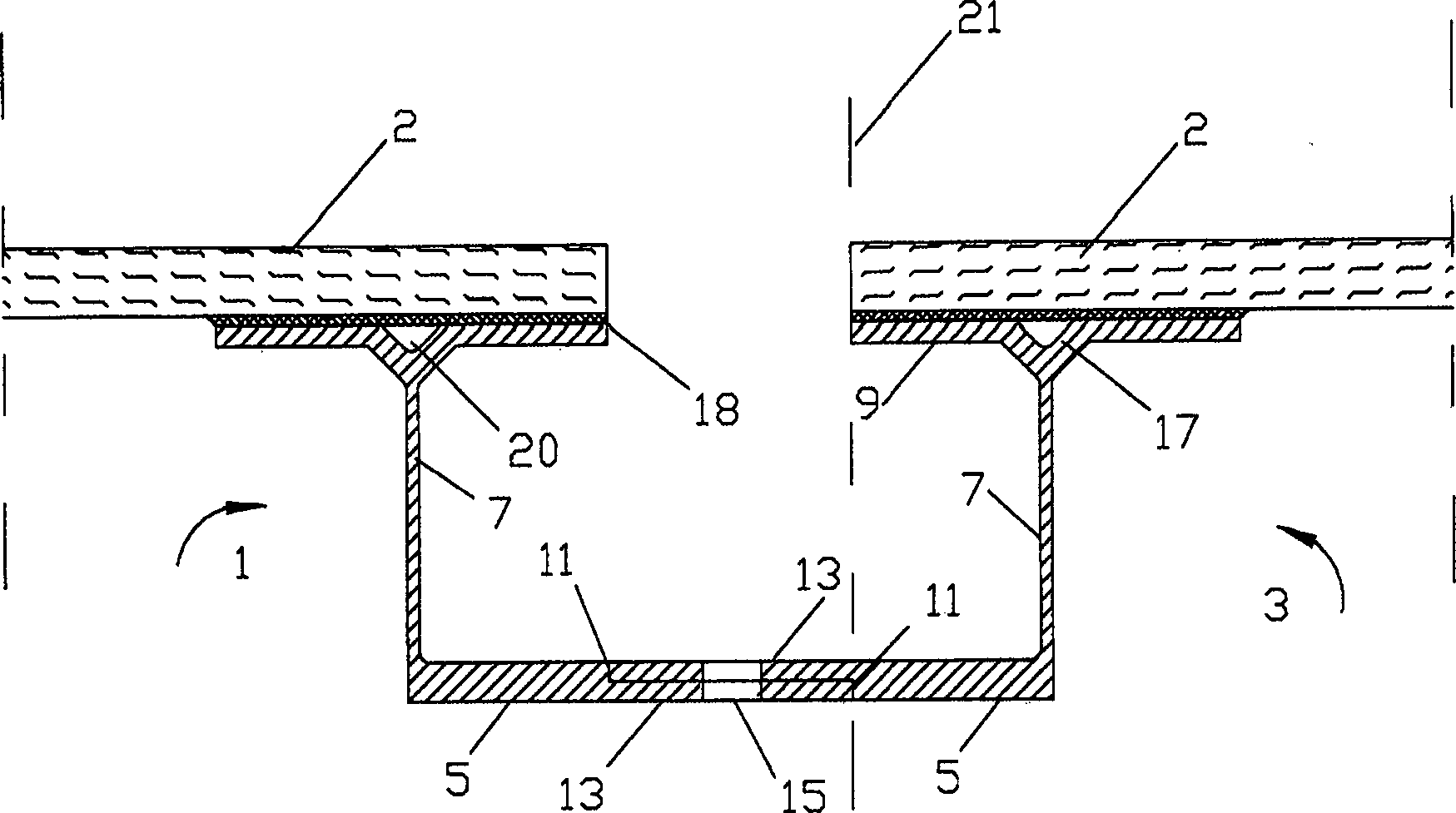
Zwei sich als Paar ergänzende, jeweils einstückige Profilleisten (1, 3) zur Montage von Photovoltaikmodulen (2), wobei sich bei jeder Profilleiste (1, 3) an einem unteren Basisteil (5) ein im wesentlichen vertikales Stützteil (7) anschließt, an dessen Ende quer ein Trägerteil (9) mit einer ebenen Befestigungsfläche parallel zum Basisteil (5) angeordnet ist, wobei das Basisteil (5) einen längs verlaufenden Absatz (11) aufweist, der einen abgestuften Ansatz (13) zur Folge hat, welcher bei einer Profilleiste (1) des Paares unten angeordnet ist und bei der anderen Profilleiste (3) des Paares oben angeordnet ist, so dass die Ansätze (13) bei zusammengeschobenen Profilleisten übereinander zu liegen kommen, wobei zumindest einer der Absätze (11) als Anschlag dient, und wobei beide Ansätze (13) mit Aussparungen (15) in gleichem Abstand versehen sind, die sich im montierten Zustand bei zusammengeschobenem Profilleistenpaar (1, 3) jeweils zumindest teilweise überdecken.Two complementary as a pair, each one-piece Moldings (1, 3) for mounting photovoltaic modules (2), wherein at each profile strip (1, 3) on a lower base part (5) a substantially vertical support member (7) connects to the End transversely, a support part (9) with a flat mounting surface parallel to the base part (5) is arranged, wherein the base part (5) has a longitudinal Paragraph (11), which results in a graduated approach (13) has, which arranged at a profile strip (1) of the pair below is and at the other profile strip (3) of the pair arranged above is, so the approaches (13) come to rest one above the other when the profile strips are pushed together, being at least one of the paragraphs (11) serves as a stop, and wherein both lugs (13) with recesses (15) are equidistant, in the assembled state at zusammengeschobenem profile strip pair (1, 3) each at least partially cover.
Description
Die Erfindung bezieht sich auf zwei sich als Paar ergänzende jeweils einstückige Profilleisten.The The invention refers to two complementary pairs one-piece Moldings.
Bei
Photovoltaikanlagen sind eine Vielzahl von Modulen matrixartig auf
einer Stützkonstruktion angeordnet.
Die Stützkonstruktion
kann z. B. zwei auf unterschiedlicher Höhe verlaufende Pfetten oder
Balken aufweisen, auf der nach Art wie es beim Dachstuhlbau der
Fall ist, Latten angeordnet sind. Eine solche Konstruktion ist beispielsweise
aus der
Eine weitere Problematik liegt bezüglich der Festigkeit der Verbindung der Profilleiste mit dem Photovoltaikmodul vor. Diese Verbindung wird üblicherweise mit Silikon vorgenommen, das die Eigenschaft hat, nur an seinem Randbereich, an dem eine ausreichende Luftzufuhr vorliegt, auszuhärten. Entsprechend ist der erforderliche Kraftschluss nur etwa 10 mm vom linken und rechten Rand der Profilleiste gewährleistet. Im mittleren Bereich bleibt die Silikonmasse weich und bewirkt nur einen schwachen Klebeeffekt.A further problem lies with respect the strength of the connection of the profile strip with the photovoltaic module in front. This connection is usually made with silicone that has the property only on his Edge area, where there is a sufficient supply of air to cure. Corresponding is the required traction only about 10 mm from the left and ensures the right edge of the profile strip. In the middle area The silicone compound remains soft and causes only a weak adhesive effect.
Aus
der
Aus
der
Aus
der
Aus
der
Aus
der
In
der
Die vorliegende Erfindung hat es sich zur Aufgabe gestellt, Mittel anzugeben, mit welchen die Kollektormodule auf einfache Weise auf die Stützkonstruktion in einem definierten Abstand zueinander aufgebracht werden können.The The present invention has for its object to provide means with which the collector modules in a simple way to the support structure can be applied at a defined distance from each other.
Die
obere, freie Seite des Trägerteils,
die dem vertikalen Stützteil
abgewandt ist, wird dabei mit dem Photovoltaikmodul (vorzugsweise
werkseitig) so verklebt, dass der Rand des Moduls bündig mit
dem Rand des Trägerteils
ist, unter dem die Ansätze
gebildet sind. Werden dann zwei Trägermodule zusammengeschoben,
ergibt sich das in der
Es ist vorteilhaft, das Trägerteil auf seiner ebenen Befestigungsfläche mit mindestens einer Nut zur Bildung des Belüftungskanals und eventuell noch zur Aufnahme überflüssigen Klebers zu versehen. Diese Maßnahme ermöglicht ein planes Aufliegen der Kollektormodule auf der oberen Trägerteilfläche. Die Nut sollte entlang der Befestigungslinie verlaufen, an der das vertikale Stützteil mit dem Trägerteil befestigt ist. Dies hat den Vorteil, dass der mit der Nut einhergehende Materialabtrag keinen großen Einfluss auf die Stabilität der Trägerfläche hat.It is advantageous, the carrier part on its flat mounting surface with at least one groove for the formation of the ventilation channel and possibly still to take superfluous glue to provide. This measure allows a planar resting of the collector modules on the upper carrier part surface. The Groove should run along the attachment line at which the vertical supporting part attached to the carrier part is. This has the advantage that the associated with the groove material removal not a big one Influence on the stability the support surface has.
Eine andere vorteilhafte Ausgestaltung der Erfindung sieht vor, dass sich der Absatz auf der Linie befindet, die sich ergibt, wenn der Rand des Trägerteils senkrecht auf das Basisteil projeziert wird. In diesem Fall wird der Spalt, der sich nach dem Zusammenbau der beiden Profilleisten zwischen deren gegenüberliegenden Rändern des Trägerteils (und damit zwischen den Photovoltaikmodulen) ergibt, durch die Breite des Ansatzes definiert. Wenn die Aussparungen mittig auf den Ansätzen angeordnet sind, liegen sie dann ebenfalls mittig zum sich ergebenden Zwischenspalt und sind mit dem Werkzeug, wie Schraubendreher oder Ratsche gut zu erreichen.Another advantageous embodiment of the invention provides that the paragraph is on the line, which results when the edge of the support member is projected perpendicular to the base part. In this case, the gap which, after assembly of the two moldings between the ge opposite edges of the support member (and thus between the photovoltaic modules) results, defined by the width of the approach. If the recesses are arranged centrally on the lugs, then they are also centered to the resulting intermediate gap and can be easily reached with the tool, such as a screwdriver or ratchet.
Es ergibt sich als wesentlicher Vorteil aller Ausführungsformen, dass das Photovoltaik-Modul frei liegt und nicht durch überstehende Bauteile verschattet wird. Ferner kann Schnee leicht abrutschen. Die Profilleiste ist selbstreinigend und sowohl als Teil- oder als Vollrahmen leicht herstellbar.It arises as a significant advantage of all embodiments that the photovoltaic module free lies and not by supernumerary Components is shadowed. Furthermore, snow can easily slip off. The Profile strip is self-cleaning and both as a partial or as a full frame easy to produce.
Der Selbstreinigung ist bei der Konstruktion von Photovoltaikmodulen eine hohe Aufmerksamkeit zu widmen. Das Modul auch oben umschließende Profilleisten führen zwangsweise zu einem Rückstand von mit Partikeln verschmutzten Regenwassers. Nach dem Abtrocknen verbleibt eine Verschmutzungsschicht, die den Lichteinfall auf das Modul und insbesondere auf dessen Photovoltaikzellen durch Reflexion und Absorption behindert und reduziert. Da die Effizienz eines Moduls von der Ausbeute der in einer Reihe liegenden schwächsten Zelle bestimmt wird, sind die nicht den Modulrand übergreifenden Profilleisten ein bedeutender Beitrag zur Erhöhung des Wirkungsgrades.Of the Self-cleaning is in the construction of photovoltaic modules to pay a lot of attention The module also enclosing profile strips above to lead forcibly to a backlog of particle-contaminated rainwater. After drying remains a dirt layer, the light on the Module and in particular on its photovoltaic cells by reflection and absorption hindered and reduced. As the efficiency of a module from the yield of the in-line weakest cell is determined, are not the module edge cross profile strips a significant contribution to the increase the efficiency.
Weitere Vorteile ergeben sich aus der Beschreibung eines Ausführungsbeispiels anhand der Figuren.Further Advantages will become apparent from the description of an embodiment based on the figures.
Es zeigen:It demonstrate:
Die
linke Hälfte
der
Das
Stützteil
Das
Basisteil
Bei
der in der
Zur
Erleichterung des Aufklebens der Profilleisten
Die
In
der
Bei
den gezeigten spiegelsymmetrisch geformten Profilleisten
Die
Ansätze
Fertigungs-
und Montagetoleranzen werden in üblicher
Weise dadurch kompensiert, dass die Aussparungen
Wenn
ein rechteckiges Photovoltaikmodul
Auf
dem Trägerteil
Zusätzlich können je
nach den vorliegenden Abmessungen und dem gewählten Klebemittel
Das
Basisteil
Die
Claims (8)
Priority Applications (1)
| Application Number | Priority Date | Filing Date | Title |
|---|---|---|---|
| DE102004055187A DE102004055187B4 (en) | 2004-11-16 | 2004-11-16 | Moldings pair for photovoltaic modules |
Applications Claiming Priority (1)
| Application Number | Priority Date | Filing Date | Title |
|---|---|---|---|
| DE102004055187A DE102004055187B4 (en) | 2004-11-16 | 2004-11-16 | Moldings pair for photovoltaic modules |
Publications (2)
| Publication Number | Publication Date |
|---|---|
| DE102004055187A1 DE102004055187A1 (en) | 2006-05-24 |
| DE102004055187B4 true DE102004055187B4 (en) | 2009-04-23 |
Family
ID=36313645
Family Applications (1)
| Application Number | Title | Priority Date | Filing Date |
|---|---|---|---|
| DE102004055187A Expired - Fee Related DE102004055187B4 (en) | 2004-11-16 | 2004-11-16 | Moldings pair for photovoltaic modules |
Country Status (1)
| Country | Link |
|---|---|
| DE (1) | DE102004055187B4 (en) |
Families Citing this family (29)
| Publication number | Priority date | Publication date | Assignee | Title |
|---|---|---|---|---|
| DE102006028494B4 (en) * | 2006-06-21 | 2011-12-08 | Zimmerei Schwörer GmbH | Support structure with solar modules on a flat roof or flat inclined roof |
| DE202007010330U1 (en) * | 2007-07-23 | 2008-08-28 | Henkenjohann, Johann | Photovoltaic modules with frames made from ALU frame profiles |
| FR2922365B1 (en) * | 2007-10-16 | 2009-12-18 | Avancis Gmbh & Co Kg | IMPROVEMENTS TO ELEMENTS CAPABLE OF COLLECTING LIGHT. |
| DE102007056600B4 (en) * | 2007-11-21 | 2011-05-05 | Solon Se | Photovoltaic system with a matrix of frameless solar modules |
| DE102008018077A1 (en) * | 2008-04-09 | 2009-11-05 | Ralos Vertriebs Gmbh | Solar element for solar systems |
| DE102008027857A1 (en) | 2008-06-11 | 2009-03-05 | Leichtmetallbau Schletter Gmbh | Mounting system for frameless thin film photovoltaic module in e.g. building open roof, has hold-securing device provided between rails having supporting surfaces and holders to counteract displacement of holders against joining direction |
| DE102008027852A1 (en) * | 2008-06-11 | 2009-12-17 | Solartec Ag | Frameless solar module for solar power system, has fastening element including three wall regions that form insertion part for insertion of fastening element in receiving pocket of prefabricated profile |
| DE102008050529A1 (en) * | 2008-10-06 | 2010-04-15 | Sunfilm Ag | Photovoltaic system, photovoltaic module, substructure and method for equipping a photovoltaic system |
| DE102008051249A1 (en) * | 2008-10-10 | 2010-04-29 | Sunfilm Ag | Photovoltaic system, photovoltaic module and method for equipping a photovoltaic system |
| DE102008051426A1 (en) * | 2008-10-11 | 2010-04-22 | Solarworld Ag | Photovoltaic module, has frame formed in manner, such that photovoltaic module is stackably secured against slipping perpendicularly to surface-normal, where frame surrounds peripheral side of semiconductor component |
| JPWO2010061878A1 (en) * | 2008-11-27 | 2012-04-26 | シャープ株式会社 | Solar cell module |
| DE202009006615U1 (en) * | 2009-05-05 | 2009-07-16 | Sulfurcell Solartechnik Gmbh | Solar energy using facade element and the façade element comprehensive facade |
| DE102009035996B4 (en) | 2009-05-19 | 2013-09-12 | Joma-Polytec Gmbh | Mounting system for photovoltaic modules on carrier strips comprising holding parts with a metallic hook element |
| DE202009008931U1 (en) | 2009-06-29 | 2009-09-24 | Meinhardt, Dirk | Building shell with solar collector module (s) and mounting system therefor |
| DE102009039246A1 (en) * | 2009-08-28 | 2011-03-10 | Sunfilm Ag | Device, system with at least two such devices and method for equipping a photovoltaic system |
| DE102009040223A1 (en) * | 2009-09-07 | 2011-03-17 | Bernhard Sossalla | Fastening device for photovoltaic, solar and / or hybrid modules |
| CN102640299A (en) * | 2009-11-05 | 2012-08-15 | 欧瑞康太阳能(处贝区市)公司 | Method for fixing a mounting element to a photovoltaic module |
| FR2952755B1 (en) * | 2009-11-16 | 2012-05-18 | Photowatt Internat | PHOTOVOLTAIC ASSEMBLY |
| DE102010005570A1 (en) * | 2010-01-22 | 2011-07-28 | VM Edelstahltechnik GmbH, 58840 | Profile element for fixing solar cells and solar cell module |
| DE202010005490U1 (en) | 2010-05-25 | 2010-07-29 | SCHÜCO International KG | Frameless solar module |
| DE202010005505U1 (en) * | 2010-05-27 | 2010-08-05 | Habdank Pv-Montagesysteme Gmbh & Co. Kg | Solar system with several flat solar modules |
| WO2012014203A2 (en) * | 2010-07-26 | 2012-02-02 | Efraim Molek | Locking mechanism for panels |
| DE102011010832A1 (en) * | 2011-02-02 | 2012-08-02 | Siegfried Ulrich | Fastening unit for fastening solar collectors on e.g. tiled roofs, has roller fixedly or lockably attached at end of lever in region formed between clamp and pressure plate, where eccentric groove is inserted over circumference of roller |
| DE102011122339B4 (en) * | 2011-12-23 | 2017-06-01 | Heinz Pöhler | Photovoltaic module with a photovoltaic unit and a module frame and method for producing a photovoltaic module |
| DE102012020355A1 (en) * | 2012-10-16 | 2014-04-17 | SGT GmbH | Solar module for mounting on roof and wall of building, has frame profiles directly connected with one another at ends of frame, so that holding portion and fastening region of frame profiles are formed adjacent to photovoltaic element |
| ES2988892T3 (en) * | 2015-12-15 | 2024-11-22 | Ml System Spolka Akcyjna | Set of structural elements suitable for removably connecting a photovoltaic module of a ventilated façade to an insulated front wall of a building |
| WO2017109827A1 (en) * | 2015-12-21 | 2017-06-29 | 株式会社東芝 | Solar panel support unit, and solar power generation system |
| US10547270B2 (en) | 2016-02-12 | 2020-01-28 | Solarcity Corporation | Building integrated photovoltaic roofing assemblies and associated systems and methods |
| US20250211162A1 (en) * | 2023-12-20 | 2025-06-26 | Nextracker Llc | Multi-glass module for a solar tracker apparatus |
Citations (11)
| Publication number | Priority date | Publication date | Assignee | Title |
|---|---|---|---|---|
| DE3916124A1 (en) * | 1989-05-18 | 1990-11-22 | Telefunken Systemtechnik | Frameless solar cell module - with inclined rim extension of support bracket reflecting solar radiation on cell edges |
| DE4014200A1 (en) * | 1989-05-18 | 1990-11-22 | Telefunken Systemtechnik | Frameless solar generator - with solar cell laminate resting on profiles with silicone adhesive pads |
| DE4416884A1 (en) * | 1994-05-13 | 1995-11-23 | Daimler Benz Aerospace Ag | Solar generator panel mechanical attachment appts. |
| DE29602315U1 (en) * | 1995-02-20 | 1997-07-03 | Glaswerke Arnold GmbH & Co. KG, 91732 Merkendorf | Glass composite panel for fixed and / or movable panes in building construction |
| DE20215462U1 (en) * | 2002-10-08 | 2003-02-06 | Kellner, Eckart, 73547 Lorch | Photovoltaic panel for solar energy collection has air heating effect used |
| JP2003056147A (en) * | 2001-08-21 | 2003-02-26 | Mitsubishi Heavy Ind Ltd | Mounting structure for solar battery panel |
| JP2003078154A (en) * | 2001-09-06 | 2003-03-14 | Mitsubishi Heavy Ind Ltd | Clasping structure for solar battery module frame |
| JP2003124493A (en) * | 2001-10-11 | 2003-04-25 | Fuji Electric Co Ltd | Solar panel and its installation method |
| DE10246161A1 (en) * | 2002-10-02 | 2004-04-22 | Beck Energie Gmbh | Longitudinally movable, rail bound working platform for mounting of solar energy modules has at least three standing areas lying on different levels, and two cut-outs are made on rear end side of platform between standing areas |
| US20040187909A1 (en) * | 2003-03-31 | 2004-09-30 | Sharp Kabushiki Kaisha | Solar cell unit and method for mounting the solar cell unit on roof |
| US20040221524A1 (en) * | 2003-05-09 | 2004-11-11 | Poddany James J. | Photovoltaic panel mounting bracket |
-
2004
- 2004-11-16 DE DE102004055187A patent/DE102004055187B4/en not_active Expired - Fee Related
Patent Citations (11)
| Publication number | Priority date | Publication date | Assignee | Title |
|---|---|---|---|---|
| DE3916124A1 (en) * | 1989-05-18 | 1990-11-22 | Telefunken Systemtechnik | Frameless solar cell module - with inclined rim extension of support bracket reflecting solar radiation on cell edges |
| DE4014200A1 (en) * | 1989-05-18 | 1990-11-22 | Telefunken Systemtechnik | Frameless solar generator - with solar cell laminate resting on profiles with silicone adhesive pads |
| DE4416884A1 (en) * | 1994-05-13 | 1995-11-23 | Daimler Benz Aerospace Ag | Solar generator panel mechanical attachment appts. |
| DE29602315U1 (en) * | 1995-02-20 | 1997-07-03 | Glaswerke Arnold GmbH & Co. KG, 91732 Merkendorf | Glass composite panel for fixed and / or movable panes in building construction |
| JP2003056147A (en) * | 2001-08-21 | 2003-02-26 | Mitsubishi Heavy Ind Ltd | Mounting structure for solar battery panel |
| JP2003078154A (en) * | 2001-09-06 | 2003-03-14 | Mitsubishi Heavy Ind Ltd | Clasping structure for solar battery module frame |
| JP2003124493A (en) * | 2001-10-11 | 2003-04-25 | Fuji Electric Co Ltd | Solar panel and its installation method |
| DE10246161A1 (en) * | 2002-10-02 | 2004-04-22 | Beck Energie Gmbh | Longitudinally movable, rail bound working platform for mounting of solar energy modules has at least three standing areas lying on different levels, and two cut-outs are made on rear end side of platform between standing areas |
| DE20215462U1 (en) * | 2002-10-08 | 2003-02-06 | Kellner, Eckart, 73547 Lorch | Photovoltaic panel for solar energy collection has air heating effect used |
| US20040187909A1 (en) * | 2003-03-31 | 2004-09-30 | Sharp Kabushiki Kaisha | Solar cell unit and method for mounting the solar cell unit on roof |
| US20040221524A1 (en) * | 2003-05-09 | 2004-11-11 | Poddany James J. | Photovoltaic panel mounting bracket |
Non-Patent Citations (3)
| Title |
|---|
| JP 2003-056 147 A (Patent Abstract of Japan); JP 2 003-078 154 A (Patent Abstract of Japan) |
| JP 2003056147 A (Patent Abstract of Japan) * |
| JP 2003078154 A (Patent Abstract of Japan) * |
Also Published As
| Publication number | Publication date |
|---|---|
| DE102004055187A1 (en) | 2006-05-24 |
Similar Documents
| Publication | Publication Date | Title |
|---|---|---|
| DE102004055187B4 (en) | Moldings pair for photovoltaic modules | |
| EP2474796B1 (en) | Ceiling hook, in particular for support structures | |
| EP1734588B1 (en) | Roofing system | |
| EP2348263A2 (en) | Profile element for fixing solar cells in place and solar cell module | |
| DE102012007535A1 (en) | Connecting element for connecting e.g. roof beam of roof truss of open area system with binder of roof truss, has surface whose section includes surface normal, which is provided in angle to surface normal of sections of other two surfaces | |
| EP2017554A2 (en) | Fixing device for flat components attachable to a framework, in particular solar modules | |
| EP1496550A2 (en) | Mounting system for framed photovoltaic modules | |
| DE202010000940U1 (en) | Profile element for fixing solar cells and solar cell module | |
| DE29606547U1 (en) | Arrangement for fastening solar modules on a roof | |
| EP2186964A1 (en) | Sheet metal roofing and solar unit on the metal roofing | |
| DE102011122339B4 (en) | Photovoltaic module with a photovoltaic unit and a module frame and method for producing a photovoltaic module | |
| WO2012019907A1 (en) | Clamping device and solar module unit | |
| EP1245754A1 (en) | Locking system for sports floors | |
| EP2109153A2 (en) | Solar element for solar assemblies | |
| DE102011122340A1 (en) | Photovoltaic system has photovoltaic modules which are attached to primary and/or secondary channel elements, and adjacent channel elements are partially overlapped with primary and secondary channel elements to form closed structure | |
| EP2246646A2 (en) | Roof hook | |
| DE202016101078U1 (en) | railing | |
| AT517212B1 (en) | Mounting system for solar module | |
| EP2944740B1 (en) | Assembly and compound body | |
| DE102012102234A1 (en) | Solar modular system for solar module kit mounted at e.g. rafter of e.g. house, has plug-in element that is provided such that similarly constructed other solar module system is plugged into aperture of rail | |
| DE19520419A1 (en) | Fixing device for balcony cladding elements to balcony | |
| DE102010028566A1 (en) | Solar module mounting device for solar system, has base plate, particularly mesh-shaped base plate, and spacer element protruding from plane of base plate | |
| AT525572B1 (en) | SOLAR SYSTEM WITH POSITIONING BAR | |
| EP2775231A1 (en) | Mounting bracket | |
| EP1857605B1 (en) | Floor covering for a building part |
Legal Events
| Date | Code | Title | Description |
|---|---|---|---|
| OP8 | Request for examination as to paragraph 44 patent law | ||
| 8122 | Nonbinding interest in granting licences declared | ||
| 8127 | New person/name/address of the applicant |
Owner name: BLITZSTROM GMBH, 97509 KOLITZHEIM, DE |
|
| 8364 | No opposition during term of opposition | ||
| R081 | Change of applicant/patentee |
Owner name: ADENSIS GMBH, DE Free format text: FORMER OWNER: BLITZSTROM GMBH, 97509 KOLITZHEIM, DE Effective date: 20110617 Owner name: BELECTRIC TRADING GMBH, DE Free format text: FORMER OWNER: BLITZSTROM GMBH, 97509 KOLITZHEIM, DE Effective date: 20110617 |
|
| R081 | Change of applicant/patentee |
Owner name: ADENSIS GMBH, DE Free format text: FORMER OWNER: BELECTRIC TRADING GMBH, 97509 KOLITZHEIM, DE |
|
| R119 | Application deemed withdrawn, or ip right lapsed, due to non-payment of renewal fee |