DE102004033114A1 - Method for calibrating a distance image sensor - Google Patents
Method for calibrating a distance image sensor Download PDFInfo
- Publication number
- DE102004033114A1 DE102004033114A1 DE102004033114A DE102004033114A DE102004033114A1 DE 102004033114 A1 DE102004033114 A1 DE 102004033114A1 DE 102004033114 A DE102004033114 A DE 102004033114A DE 102004033114 A DE102004033114 A DE 102004033114A DE 102004033114 A1 DE102004033114 A1 DE 102004033114A1
- Authority
- DE
- Germany
- Prior art keywords
- calibration
- distance image
- image sensor
- vehicle
- determined
- Prior art date
- Legal status (The legal status is an assumption and is not a legal conclusion. Google has not performed a legal analysis and makes no representation as to the accuracy of the status listed.)
- Withdrawn
Links
- 238000000034 method Methods 0.000 title claims abstract description 48
- 238000001514 detection method Methods 0.000 claims abstract description 28
- 238000003384 imaging method Methods 0.000 claims description 11
- 230000005670 electromagnetic radiation Effects 0.000 claims description 6
- 230000005672 electromagnetic field Effects 0.000 abstract 1
- 239000013598 vector Substances 0.000 description 15
- 238000012545 processing Methods 0.000 description 9
- 238000005259 measurement Methods 0.000 description 8
- 230000009466 transformation Effects 0.000 description 6
- 230000005855 radiation Effects 0.000 description 5
- 239000011159 matrix material Substances 0.000 description 4
- 230000003287 optical effect Effects 0.000 description 3
- 238000013519 translation Methods 0.000 description 3
- 238000012937 correction Methods 0.000 description 2
- 239000005337 ground glass Substances 0.000 description 2
- 238000009434 installation Methods 0.000 description 2
- 238000012417 linear regression Methods 0.000 description 2
- 238000012544 monitoring process Methods 0.000 description 2
- 238000006243 chemical reaction Methods 0.000 description 1
- 238000004590 computer program Methods 0.000 description 1
- 238000005520 cutting process Methods 0.000 description 1
- 238000011161 development Methods 0.000 description 1
- 230000018109 developmental process Effects 0.000 description 1
- 238000011156 evaluation Methods 0.000 description 1
- 238000010191 image analysis Methods 0.000 description 1
- 238000011835 investigation Methods 0.000 description 1
- 238000004519 manufacturing process Methods 0.000 description 1
- 238000005457 optimization Methods 0.000 description 1
- 238000003909 pattern recognition Methods 0.000 description 1
- 238000007781 pre-processing Methods 0.000 description 1
- 230000000717 retained effect Effects 0.000 description 1
- 238000001228 spectrum Methods 0.000 description 1
- 230000002123 temporal effect Effects 0.000 description 1
- 238000012549 training Methods 0.000 description 1
- 238000000844 transformation Methods 0.000 description 1
Classifications
-
- G—PHYSICS
- G01—MEASURING; TESTING
- G01S—RADIO DIRECTION-FINDING; RADIO NAVIGATION; DETERMINING DISTANCE OR VELOCITY BY USE OF RADIO WAVES; LOCATING OR PRESENCE-DETECTING BY USE OF THE REFLECTION OR RERADIATION OF RADIO WAVES; ANALOGOUS ARRANGEMENTS USING OTHER WAVES
- G01S7/00—Details of systems according to groups G01S13/00, G01S15/00, G01S17/00
- G01S7/48—Details of systems according to groups G01S13/00, G01S15/00, G01S17/00 of systems according to group G01S17/00
- G01S7/497—Means for monitoring or calibrating
- G01S7/4972—Alignment of sensor
-
- G—PHYSICS
- G01—MEASURING; TESTING
- G01S—RADIO DIRECTION-FINDING; RADIO NAVIGATION; DETERMINING DISTANCE OR VELOCITY BY USE OF RADIO WAVES; LOCATING OR PRESENCE-DETECTING BY USE OF THE REFLECTION OR RERADIATION OF RADIO WAVES; ANALOGOUS ARRANGEMENTS USING OTHER WAVES
- G01S17/00—Systems using the reflection or reradiation of electromagnetic waves other than radio waves, e.g. lidar systems
- G01S17/86—Combinations of lidar systems with systems other than lidar, radar or sonar, e.g. with direction finders
-
- G—PHYSICS
- G01—MEASURING; TESTING
- G01S—RADIO DIRECTION-FINDING; RADIO NAVIGATION; DETERMINING DISTANCE OR VELOCITY BY USE OF RADIO WAVES; LOCATING OR PRESENCE-DETECTING BY USE OF THE REFLECTION OR RERADIATION OF RADIO WAVES; ANALOGOUS ARRANGEMENTS USING OTHER WAVES
- G01S17/00—Systems using the reflection or reradiation of electromagnetic waves other than radio waves, e.g. lidar systems
- G01S17/88—Lidar systems specially adapted for specific applications
- G01S17/93—Lidar systems specially adapted for specific applications for anti-collision purposes
- G01S17/931—Lidar systems specially adapted for specific applications for anti-collision purposes of land vehicles
-
- G—PHYSICS
- G01—MEASURING; TESTING
- G01S—RADIO DIRECTION-FINDING; RADIO NAVIGATION; DETERMINING DISTANCE OR VELOCITY BY USE OF RADIO WAVES; LOCATING OR PRESENCE-DETECTING BY USE OF THE REFLECTION OR RERADIATION OF RADIO WAVES; ANALOGOUS ARRANGEMENTS USING OTHER WAVES
- G01S7/00—Details of systems according to groups G01S13/00, G01S15/00, G01S17/00
- G01S7/02—Details of systems according to groups G01S13/00, G01S15/00, G01S17/00 of systems according to group G01S13/00
- G01S7/40—Means for monitoring or calibrating
- G01S7/4004—Means for monitoring or calibrating of parts of a radar system
- G01S7/4026—Antenna boresight
-
- G—PHYSICS
- G01—MEASURING; TESTING
- G01S—RADIO DIRECTION-FINDING; RADIO NAVIGATION; DETERMINING DISTANCE OR VELOCITY BY USE OF RADIO WAVES; LOCATING OR PRESENCE-DETECTING BY USE OF THE REFLECTION OR RERADIATION OF RADIO WAVES; ANALOGOUS ARRANGEMENTS USING OTHER WAVES
- G01S7/00—Details of systems according to groups G01S13/00, G01S15/00, G01S17/00
- G01S7/02—Details of systems according to groups G01S13/00, G01S15/00, G01S17/00 of systems according to group G01S13/00
- G01S7/40—Means for monitoring or calibrating
- G01S7/4052—Means for monitoring or calibrating by simulation of echoes
- G01S7/4082—Means for monitoring or calibrating by simulation of echoes using externally generated reference signals, e.g. via remote reflector or transponder
- G01S7/4086—Means for monitoring or calibrating by simulation of echoes using externally generated reference signals, e.g. via remote reflector or transponder in a calibrating environment, e.g. anechoic chamber
Landscapes
- Engineering & Computer Science (AREA)
- Physics & Mathematics (AREA)
- Radar, Positioning & Navigation (AREA)
- Remote Sensing (AREA)
- Computer Networks & Wireless Communication (AREA)
- General Physics & Mathematics (AREA)
- Electromagnetism (AREA)
- Measurement Of Optical Distance (AREA)
- Length Measuring Devices By Optical Means (AREA)
- Optical Radar Systems And Details Thereof (AREA)
- Radar Systems Or Details Thereof (AREA)
Abstract
Bei dem Verfahren zur wenigstens teilweisen Kalibrierung eines an einem Fahrzeug gehaltenen Abstandsbildsensors für elektromagnetische Strahlung, mittels dessen ein Erfassungsbereich entlang wenigstens einer Abtastfläche abtastbar und ein entsprechendes Abstandsbild erfassbar ist, in Bezug auf eine Ausrichtung der Abtastfläche oder des Abstandsbildsensors relativ zu dem Fahrzeug werden mittels des Abstandsbildsensors Abstände zwischen dem Abstandsbildsensor und Bereichen auf wenigstens einer Kalibrierfläche ermittelt und unter Verwendung der ermittelten Abstände wird ein Wert für eine die Ausrichtung wenigstens teilweise beschreibende Größe ermittelt.at the method for at least partially calibrating a on a Vehicle-mounted electromagnetic field proximity sensor, by means of which a detection area can be scanned along at least one scanning area and a corresponding distance image is detectable with respect to an alignment of the scanning surface or the distance image sensor relative to the vehicle are by means of of the distance image sensor distances between the distance image sensor and areas on at least one gage determined and using the distances determined is a Value for determines a size at least partially descriptive size.
Description
Die vorliegende Erfindung betrifft ein Verfahren zur Kalibrierung eines an einem Fahrzeug gehaltenen Abstandsbildsensors für elektromagnetische Strahlung, mittels dessen ein Erfassungsbereich entlang wenigstens einer Abtastfläche abtastbar und ein entsprechendes Abstandsbild erfassbar ist.The The present invention relates to a method for calibrating a On a vehicle held distance image sensor for electromagnetic Radiation, by means of which a detection area along at least a scanning surface be scanned and a corresponding distance image can be detected.
Abstandsbildsensoren sind grundsätzlich bekannt. Mit ihnen können Abstandsbilder ihres Erfassungsbereichs erfasst werden, deren Abstandsbildpunkte Daten in Bezug auf die Lage entsprechender erfasster Punkte bzw. Bereiche auf Gegenständen und insbesondere in Bezug auf den Abstand von dem Abstandsbildsensor enthalten. Der Erfassungsbereich umfasst dabei häufig wenigstens eine Abtastfläche, unter der im Rahmen der Erfindung eine Fläche verstanden wird, auf bzw. in der Punkte bzw. Bereiche auf Gegenständen erfassbar sind.Distance image sensors are basically known. With them you can Distance images of their detection area are detected, their distance pixels Data relating to the location of corresponding detected points or Areas on objects and in particular with respect to the distance from the distance image sensor contain. The detection area often comprises at least one scanning area, below in the context of the invention, an area is understood on or in which points or areas on objects can be detected.
Ein Beispiel für einen solchen Abstandsbildsensor ist ein Laserscanner, der ein gepulstes Laserstrahlbündel durch seinen Erfassungsbereich schwenkt und winkelaufgelöst von Gegenständen zurückgeworfene Strahlung des Laserstrahlbündels detektiert. Aus der Laufzeit der Laserpulse von deren Abgabe bis zur Detektion von Gegenständen zurückgeworfener Anteile der Laserpulse kann der Abstand ermittelt werden. Das geschwenkte Laserstrahlbündel und der Empfangsbereich, aus dem zurückgeworfene Strahlung durch einen Detektor des Laserscanners empfang- und detektierbar ist, definieren hierbei die Abtastfläche.One example for such a distance image sensor is a laser scanner, which is a pulsed laser beam through its detection range pivots and angular resolution of objects thrown back radiation of the laser beam detected. From the duration of the laser pulses from their delivery to for the detection of objects Discarded Shares of the laser pulses, the distance can be determined. The swiveled laser beam and the reception area, from the reflected radiation a detector of the laser scanner can be detected and detected, thereby defining the scanning surface.
Solche Abstandsbildsensoren können vorteilhaft zur Überwachung eines Überwachungsbereichs vor, neben und/oder hinter einem Kraftfahrzeug eingesetzt werden. Um die Lage detektierter Gegenstände relativ zu dem Fahrzeug genau bestimmen zu können, müssen die Lage und Ausrichtung des Abstandsbildsensors und damit auch der Abtastfläche relativ zu dem Fahrzeug genau bekannt sein. Bedingt durch ungenauen Einbau kann der Abstandsbildsensor jedoch gegenüber der Fahrzeuglängs-, -hoch- und/oder -querachse gedreht sein, sodass die Ausrichtung des Abstandsbildsensors zu dem Fahrzeug nicht den Vorgaben entspricht. Um solche Abweichungen durch Justierung oder Maßnahmen bei der Verarbeitung der Daten des Abstandsbildsensors wenigstens teilweise kompensieren zu können, ist es wünschenswert dessen Ausrichtung möglichst genau ermitteln zu können. Entsprechende Probleme können bei der Verwendung von Videosensoren wie beispielsweise Videokameras auftreten.Such Distance image sensors can advantageous for monitoring a surveillance area be used before, next to and / or behind a motor vehicle. To the location of detected objects relative to the vehicle to be able to accurately determine the location and orientation the distance image sensor and thus the scanning relatively be known exactly to the vehicle. Due to inaccurate installation However, the distance image sensor can with respect to the vehicle longitudinal, vertical and / or transverse axis be rotated so that the orientation of the distance image sensor to the vehicle does not meet the specifications. To such deviations by adjustment or measures in the processing of the data of the distance image sensor at least partially compensate, it is desirable its orientation as possible to be able to determine exactly. Corresponding problems can when using video sensors such as video cameras occur.
Der vorliegenden Erfindung liegt daher die Aufgabe zugrunde, ein Verfahren der oben genannten Art bereitzustellen, mittels dessen eine wenigstens teilweise Kalibrierung in Bezug auf die Ausrichtung des Abstandsbildsensors relativ zu dem Fahrzeug mit guter Genauigkeit durchführbar ist.Of the The present invention is therefore based on the object, a method of the above type, by means of which at least one partial calibration with respect to the orientation of the distance image sensor relative to the vehicle with good accuracy is feasible.
Die Aufgabe wird gelöst durch ein Verfahren mit den Merkmalen des Anspruchs 1.The Task is solved by a method having the features of claim 1.
Bei dem erfindungsgemäßen Verfahren zur wenigstens teilweisen Kalibrierung eines an einem Fahrzeug gehaltenen Abstandsbildsensors für elektromagnetische Strahlung, mittels dessen ein Erfassungsbereich entlang wenigstens einer Abtastfläche abtastbar und ein entsprechendes Abstandsbild erfassbar ist, in Bezug auf eine Ausrichtung der Abtastfläche oder des Abstandsbildsensors relativ zu dem Fahrzeug werden mittels des Abstandsbildsensors Abstände zwischen dem Abstandsbildsensor und Bereichen auf wenigstens einer Kalibrierfläche ermittelt und unter Ver wendung der ermittelten Abstände wird ein Wert für eine die Ausrichtung wenigstens teilweise beschreibende Größe ermittelt.at the method according to the invention for at least partially calibrating a vehicle Distance image sensor for electromagnetic radiation, by means of which a detection area Scannable along at least one scanning and a corresponding Distance image is detected, with respect to an orientation of the scanning or of the distance image sensor relative to the vehicle are detected by means of the Distance image sensor distances between the distance image sensor and areas on at least one gage determined and using the distances determined a value for determines a size at least partially descriptive size.
Wie eingangs erwähnt wird im Rahmen der Erfindung unter einem Abstandsbildsensor für elektromagnetische Strahlung ein Sensor verstanden, mittels dessen Abstandsbilder des Erfassungsbereichs unter Verwendung elektromagnetischer Strahlung erfassbar sind, die Daten in Bezug auf den Abstand von erfassten Gegenstandspunkten zu dem Abstandsbildsensor bzw. einem diesem fest zugeordneten Referenzpunkte enthalten. Beispielsweise können entsprechende Radarsensoren verwendet werden.As mentioned in the beginning is in the context of the invention under a distance image sensor for electromagnetic Radiation understood a sensor by means of whose distance images of the Detection range using electromagnetic radiation can be detected, the data in relation to the distance from detected object points to the distance image sensor or a fixed reference points assigned to this contain. For example, you can corresponding radar sensors are used.
Vorzugsweise werden Laserscanner verwendet, die den Erfassungsbereich mit optischer Strahlung, d.h. elektromagnetischer Strahlung im Infrarotbereich, dem sichtbaren Bereich oder dem Ultraviolettbereich des elektromagnetischen Spektrums, abtasten. Insbesondere können Laserscanner verwendet werden, die wenigstens ein gepulstes Laserstrahlbündel durch den Erfassungsbereich bewegen, vorzugsweise schwenken, und von Gegenständen zurückgeworfene Strahlung detektieren. Aus der Pulslaufzeit von dem Abstandsbildsensor zu dem Gegenstand und zurück zu dem Abstandsbildsensor und zurück kann dann der Abstand erfasst werden.Preferably, laser scanners are used which scan the detection area with optical radiation, ie electromagnetic radiation in the infrared range, the visible range or the ultraviolet range of the electromagnetic spectrum. In particular, laser scanners can be used which move at least one pulsed laser beam through the detection area, preferably pivot, and detect radiation reflected from objects. From the pulse duration of the distance Image sensor to the object and back to the distance image sensor and back then the distance can be detected.
Der Abstandsbildsensor weist wenigstens eine Abtastfläche auf, entlang derer Gegenstände detektierbar sind. Die Abtastfläche kann beispielsweise bei einem Laserscanner durch den abgegebenen Abtaststrahl und gegebenenfalls dessen Bewegung und/oder den Empfangsbereich des Laserscanners für von erfassten Gegenständen zurückgeworfene Strahlung definiert sein. Die Lage der Abtastfläche ist relativ zu dem Abstandsbildsensor durch den Aufbau und/oder gegebenenfalls eine Betriebsart des Abstandsbildsensors festgelegt und vorzugsweise bekannt. Die Abtastfläche braucht keine Ebene zu sein, vorzugsweise ist dies jedoch der Fall.Of the Distance image sensor has at least one scanning surface, along those objects are detectable. The scanning surface For example, in a laser scanner by the delivered Scanning beam and optionally its movement and / or the receiving area of the laser scanner for of detected objects reflected Be defined radiation. The location of the scanning area is relative to the distance image sensor by the structure and / or possibly an operating mode of the distance image sensor determined and preferably known. The scanning surface needs However, this is not the case.
Zur wenigstens teilweisen Ermittlung der Ausrichtung des Abstandsbildsensors und/oder der Abtastfläche wird erfindungsgemäß wenigstens eine Kalibrierfläche verwendet. Unter Kalibrierfläche wird dabei insbesondere auch ein Flächenabschnitt einer größeren Fläche verstanden, der für die Kalibrierung verwendet wird.to at least partially determining the orientation of the distance image sensor and / or the scanning surface is at least according to the invention a calibration surface used. Under calibration surface In this case, in particular, a surface section of a larger area is understood, the for the calibration is used.
Unter der Ausrichtung des Abstandsbildsensors oder der Abtastfläche wird erfindungsgemäß die Orientierung des Abstandsbildsensors oder der Abtastfläche und die Winkellage wenigstens einer Bezugsachse des Abstandsbildsensors oder einer Bezugsrichtung der Abtastfläche wenigstens näherungsweise entlang der Abtastfläche relativ zu dem Fahrzeug bzw. einem entsprechenden Bezugssystem verstanden. Dabei wird unter der Orientierung der Abtastfläche zu dem Fahrzeug insbesondere auch die Orientierung eines Normalenvektors auf den Abtastfläche an einer vorgegebenen Position relativ zu einer durch die Fahrzeuglängs- und -querachse gegebenen Fahrzeugebene oder einer Aufstandsfläche, auf der das Fahrzeug steht, verstanden. Die Soll-Ausrichtung des Sensors bzw. der Abtastfläche relativ zu dem Sensor kann grundsätzlich beliebig sein, beispielsweise kann diese mit der Aufstandsfläche einen Winkel von 90° bilden, bevorzugt bildet die Abtastfläche in der Soll-Ausrichtung jedoch mit der Aufstandsfläche eine Winkel kleiner als 15°.Under the orientation of the distance image sensor or the scanning becomes According to the invention, the orientation of the distance image sensor or the scanning surface and the angular position at least a reference axis of the distance image sensor or a reference direction the scanning surface at least approximately along the scanning surface understood relative to the vehicle or a corresponding reference system. In this case, under the orientation of the scanning surface to the vehicle in particular also the orientation of a normal vector on the scanning surface on a predetermined position relative to a through the Fahrzeuglängs- and -querachse given vehicle level or a footprint on which the vehicle is standing, Understood. The target orientation of the sensor or the scanning relative Basically to the sensor be any, for example, this can with the footprint one Form angles of 90 °, The scanning surface preferably forms in the target orientation, however, with the footprint one Angle smaller than 15 °.
Die Ausrichtung des Abstandsbildsensors kann daher mit entsprechenden Größen bzw. Variablen beschrieben werden. Beispielsweise kann wenigstens ein entsprechender Winkel oder Winkelcosinus verwendet werden. Zur vollständigen Beschreibung der Orientierung sind dabei wenigstens zwei Größen notwendig.The Alignment of the distance image sensor can therefore with appropriate Sizes or Variables are described. For example, at least one corresponding angle or angle cosine can be used. For a complete description Orientation requires at least two sizes.
Zur wenigstens teilweisen Beschreibung der Orientierung kann ein die Orientierung wenigstens teilweise wiedergebenden Orientierungswinkel, insbesondere einen Nickwinkel, der die Orientierung der Abtastfläche bzw. des Abstandsbildsensors relativ zu der Fahrzeuglängsachse wiedergibt, und/oder einen Wankwinkel, der die Orientierung der Abtastfläche bzw. des Abstandsbildsensors relativ zu der Fahrzeugquerachse wiedergibt, verwendet werden. In Bezug auf die Winkellage kann ein Gierwinkel zwischen einer vorgegebenen Bezugsachse des Abstandsbildsensors wenigstens näherungsweise entlang der Abtastfläche und einer entsprechenden vorgegebenen Bezugsachse des Fahrzeugs parallel zu der Fahrzeuglängs- und/oder -querachse als die Ausrichtung teilweise beschreibende Größe verwendet werden.to At least partial description of the orientation can be a the Orientation at least partially reflecting the orientation angle, In particular, a pitch angle, the orientation of the scanning or of the distance image sensor relative to the vehicle longitudinal axis, and / or a roll angle, the orientation of the scanning or the distance image sensor relative to the vehicle transverse axis, be used. In terms of angular position, a yaw angle between a predetermined reference axis of the distance image sensor at least approximately along the scanning surface and a corresponding predetermined reference axis of the vehicle parallel to the vehicle longitudinal and / or transverse axis be used as the orientation partially descriptive size.
Erfindungsgemäß genügt es, dass nur der Wert einer die Ausrichtung wiedergebenden Größe, beispielsweise ein Orientierungswinkel oder ein Gierwinkel, bestimmt wird, vorzugsweise werden jedoch Werte wenigstens zweier die Orientierung wiedergebenden Größen ermittelt. Besonders bevorzugt wird darüber hinaus auch eine die Winkellage wiedergebende Größe ermittelt.According to the invention, it is sufficient that only the value of a size reflecting the orientation, for example an orientation angle or yaw angle is determined, preferably However, values of at least two reflect the orientation Sizes determined. It is especially preferred In addition, also determines the angular position reproducing size.
Erfindungsgemäß werden mittels des Abstandsbildsensors Abstände zwischen dem Abstandsbildsensor und Bereichen auf der Kalibrierfläche ermittelt. Unter Verwendung der ermittelten Abstände und gegebenenfalls weiterer Parameter wird dann der Wert der die Ausrichtung wenigstens teilweise wiedergebenden Größe bestimmt.According to the invention by means of the distance image sensor distances between the distance image sensor and ranges determined on the calibration surface. Under use the determined distances and optionally further parameters then the value of the Orientation determined at least partially reproducing size.
Durch die Verwendung von Abstandsmessungen, die eine höhere Genauigkeit als Winkelmessungen, beispielsweise bei Laserscannern, aufweisen, kann so eine genaue Kalibrierung erreicht werden.By the use of distance measurements, which is more accurate than angle measurements, for example in laser scanners, such an accurate calibration can be achieved become.
Weiterbildungen und bevorzugte Ausführungsformen der Erfindung sind in den Ansprüchen, der Beschreibung und den Zeichnungen beschrieben.further developments and preferred embodiments of the invention are defined in the claims, the description and the drawings.
Um die Genauigkeit der Kalibrierung zu erhöhen, können vorzugsweise mehrere Abstandsbilder erfasst werden, über die dann gemittelt wird. Insbesondere kann ein zeitliches Mittel gebildet werden. Vorzugsweise werden dazu die bei mehreren Abtastungen erfassten Abstandsbildpunkte derselben Abtastfläche zu einem Gesamtabstandsbild zusammengefasst und gemeinsam ausgewertet.Around To increase the accuracy of the calibration, preferably a plurality of distance images be captured over which is then averaged. In particular, a time average be formed. Preferably, these are the case with multiple scans captured distance pixels of the same scanning area to a total distance image summarized and evaluated together.
Um eine möglichst hohe Genauigkeit bei der Kalibrierung auch bei Erfassung nur eines Abstandsbildes oder nur weniger Abstandsbilder zu erhalten, ist es bevorzugt, dass eine Kalibrierfläche mit einer bekannten Form verwendet wird, auf der zur Kalibrierung mittels des Abstandsbildsensors wenigstens zwei entlang der Abtastfläche benachbarte Bereiche ortsaufgelöst erfassbar sind. Auf diese Weise kann die Ausrichtung der Abtastfläche bzw. des Abstandsbildsensors zu der Kalibrierfläche unter Verwendung von wenigstens zwei entsprechenden Abstandsbildpunkten wenigstens eines einzelnen Abstandsbildes genauer bestimmt werden. Insbesondere ist es möglich, Mittelwerte auf der Basis mehrerer erfasster Abstandsbildpunkte eines einzelnen Abstandsbildes zu bilden und damit Fehler der Winkelermittlung bei Laserscannern teilweise zu kompensieren, wodurch die Genauigkeit der Kalibrierung verbessert werden kann.Around one possible high accuracy in the calibration even with detection of only one Is to obtain distance image or only a few distance images it is preferred that a calibration surface with a known shape is used on the calibration by means of the distance image sensor at least two areas along the scanning adjacent areas spatially resolved detectable are. In this way, the orientation of the scanning or of the distance image sensor to the calibration surface using at least two corresponding distance pixels of at least one individual Distance image can be determined more accurately. In particular, it is possible to average values based on a plurality of acquired distance pixels of a single distance image and thus errors of the angle determination in laser scanners partially compensate, reducing the accuracy of calibration can be improved.
Weiterhin ist es bevorzugt, dass ein Abstandsbildsensor kalibriert wird, mittels dessen der Erfassungsbereich entlang wenigstens zweier verschiedener Abtastflächen abtastbar ist. Solche Abstandsbildsensoren eignen sich insbesondere für den Fahrzeugbereich, da durch die Verwendung von zwei Abtastflächen trotz Nickbewegungen des Fahrzeugs in der Regel wenigstens ein einer Abtastfläche entsprechendes Abstandsbild verfügbar ist. Ein Laserscanner mit wenigstens zwei Abtastflächen ist beispielsweise in der deutschen Patentanmeldung mit dem amtlichen Aktenzeichen 10143060.4 beschrieben, deren Inhalt hiermit durch Bezugnahme in die Beschreibung aufgenommen wird.Farther It is preferable that a distance image sensor is calibrated by means of of which the detection area along at least two different scanning surfaces is palpable. Such distance image sensors are particularly suitable for the Vehicle area, there by the use of two sensing surfaces despite pitching movements of the vehicle, as a rule, at least one scanning surface Distance image available is. A laser scanner with at least two scanning surfaces is For example, in the German patent application with the official Reference number 10143060.4 described, the contents of which are hereby by Reference is included in the description.
Insbesondere in diesem Fall ist es dann bevorzugt, dass ein Abstandsbildsensor kalibriert wird, für den die Lage und/oder Ausrichtung der Abtastfläche relativ zu einem Koordinatensystem des Abstandsbildsensors bekannt ist, dass für Abstandsbildpunkte des erfassten Abstandsbildes, die der Abtastfläche zugeordnet sind, Koordinaten in dem Koordinatensystem des Abstandsbildsensors ermittelt werden, und dass diese Koordinaten zur wenigstens teilweisen Ermittlung der Ausrichtung verwendet werden. Dieses Vorgehen ist besonders vorteilhaft bei Abstandsbildsensoren, bei denen keine entsprechende Korrektur vorgesehen ist, sondern die Koordinaten in dem Koordinatensystem des Abstandsbildsensors nur näherungsweise ermittelt werden. Zur Durchführung kann insbesondere eine Lage in der Abtastfläche erfasst werden, die dann mittels einer bekannten Funktion in entsprechende Koordinaten in dem Koordinatensystem umgerechnet werden kann. Diese Weiterbildung ist beispielsweise bei Abstandsbildsensoren mit mehreren wenigstens abschnittsweise gegeneinander geneigten Abtastflächen vorteilhaft, da hier andernfalls Ungenauigkeiten durch die Relativneigung der Abtastflächen zueinander entstehen können.Especially in this case, it is then preferable that a distance image sensor is calibrated for the location and / or orientation of the scanning relative to a coordinate system of the distance image sensor is known that for distance pixels of the detected Distance image, the scanning surface are assigned coordinates in the coordinate system of the distance image sensor be determined, and that these coordinates to at least partially Determining the orientation to be used. This procedure is particularly advantageous in distance image sensors, where no Corresponding correction is provided, but the coordinates in the coordinate system of the distance image sensor only approximately be determined. To carry out In particular, a position in the scanning surface can be detected, which then by means of a known function in corresponding coordinates in the coordinate system can be converted. This training is for example in distance image sensors with several at least partially mutually inclined scanning surfaces advantageous because otherwise Inaccuracies due to the relative inclination of the sensing surfaces to each other can arise.
Nach einer ersten Alternative ist es bei Verwendung eines Abstandsbildsensors mit wenigstens zwei Abtastflächen bevorzugt, dass in den beiden Abtastflächen jeweils erfasste Bereiche gemeinsam zur wenigstens teilweisen Ermittlung der Ausrichtung verwendet werden. Hierdurch kann eine besonders einfache Verarbeitung der Daten erfolgen.To A first alternative is when using a distance image sensor with at least two scanning surfaces preferred that in each of the two sensing surfaces detected areas used together to at least partially determine the orientation become. This allows a particularly simple processing of Data is done.
Nach einer zweiten Alternative ist es bevorzugt, dass aus den Abständen von erfassten Bereichen auf der Kalibrierfläche zu dem Abstandsbildsensor für jede der Abtastflächen ein der jeweiligen Abtastfläche zugeordneter Wert für die die Ausrichtung wenigstens teilweise wiedergebende Größe ermittelt wird, und dass aus den den Abtastflächen zugeordneten Werten ein Wert für die die Ausrichtung des Abstandsbildsensors wenigstens teilweise wiedergebende Größe ermittelt wird. Mit anderen Worten werden wenigstens teilweise die Ausrichtungen der Abstandsflächen unabhängig voneinander ermittelt und aus diesen die Ausrichtung des Abstandsbildsensors selbst bzw. eines Koordinatensystems des Abstandsbildsensors bestimmt. Hiermit ist eine große Genauigkeit erzielbar.To In a second alternative, it is preferable that from the distances of detected areas on the calibration surface to the distance image sensor for every the scanning surfaces one of the respective scanning surface assigned value for which determines the orientation at least partially reproducing size and that from the values assigned to the scanning surfaces Value for the orientation of the distance image sensor at least partially determining size becomes. In other words, the orientations become at least partially the distance surfaces independently determined from each other and from these the orientation of the distance image sensor itself or a coordinate system of the distance image sensor. This is a big one Accuracy achievable.
Um eine besonders einfache Kalibrierung zu ermöglichen, ist es bevorzugt, dass die Kalibrierfläche eben ist. In diesem Fall haben Ungenauigkeiten der Lage der Kalibrierflächen relativ zu dem Abstandsbildsensor bei der Kalibrierung einen nur relativ geringen Einfluss.Around to allow a particularly simple calibration, it is preferable that the calibration surface is level is. In this case, inaccuracies in the position of the calibration surfaces are relative to the distance image sensor in the calibration only a relative low influence.
Zur Ermittlung der Orientierung der Abtastfläche, die beispielsweise durch die Orientierung eines Normalenvektors auf die Abtastfläche an einem vorgegebenen Ort auf der Abtastfläche gegeben sein kann, ist es bevorzugt, dass zur wenigstens teilweisen Bestimmung einer Orientierung der Abtastfläche oder des Abstandsbildsensors relativ zu dem Fahrzeug, insbesondere eines Nickwinkels, die Bereiche der Kalibrierfläche jeweils relativ zu der Fahrzeuglängs- oder -hochachse in vorgegebener Weise geneigt sind, und dass aus den erfassten Abständen der von dem Abstandsbildsensor erfassten Bereiche in Abhängigkeit von deren Neigungen ein Wert für eine die Orientierung wenigstens teilweise wiedergebende Größe, insbesondere den Nickwinkel, ermittelt wird. Grundsätzlich kann sich die Ausrichtung der Kalibrierfläche nach der Soll-Lage der Abtastflä che in Bezug auf das Fahrzeug richten. Sie bildet mit dieser vorzugsweise einen Winkel von weniger als 90°. Insbesondere kann die Kalibrierfläche gegenüber einer ebenen Aufstandsfläche, auf der das Fahrzeug bei der Erfassung des Abstandsbildes bzw. bei der Kalibrierung steht, geneigt sein, nicht aber orthogonal zu dieser verlaufen. Auf diese Weise kann der Abstand des Schnitts der Abtastfläche mit der Kalibrierfläche von der Aufstandsfläche bzw. einer entsprechenden Ebene eines Fahrzeugkoordinatensystems oder eine Neigung der Abtastfläche im Bereich der Kalibrierfläche relativ zu der Aufstandsfläche bzw. der entsprechenden Ebene des Fahrzeugkoordinatensystems allein durch Abstandsmessungen ermittelt werden, die beispielsweise bei Laserscannern eine verglichen mit Winkelmessungen hohe Genauigkeit aufweisen. Die Ermittlung braucht dabei nicht auf der Basis nur eines entsprechenden Abstandsbildpunktes zu erfolgen, vielmehr können aus erfassten Abstandbildpunkten auch Bezugspunkte ermittelt werden, die dann zur eigentlichen Höhen- bzw. Neigungsermittlung herangezogen werden.In order to determine the orientation of the scanning surface, which may be given for example by the orientation of a normal vector on the scanning surface at a predetermined location on the scanning surface, it is preferred that at least partially determine an orientation of the scanning surface or the distance image sensor relative to the vehicle, in particular a pitch angle, the areas of the calibration area are respectively inclined relative to the vehicle longitudinal or vertical axis in a predetermined manner, and that from the detected distances of the detected by the distance image sensor areas depending on their inclinations, a value for an orientation at least partially reproducing size, in particular the pitch angle, is determined. In principle, the orientation of the calibration surface can be based on the desired position of the Abtastflä surface with respect to the vehicle. It forms with this preferably an angle of less than 90 °. In particular, the calibration surface may be inclined relative to a flat contact surface on which the vehicle stands during the detection of the distance image or during calibration, but not orthogonal to it run. In this way, the distance of the intersection of the scanning surface with the calibration surface of the footprint or a corresponding plane of a vehicle coordinate system or an inclination of the scanning in the region of the calibration relative to the footprint or the corresponding plane of the vehicle coordinate system can be determined solely by distance measurements, the For example, in laser scanners have a high accuracy compared to angle measurements. In this case, the determination need not be made on the basis of only one corresponding distance image point, but rather, reference points can also be determined from detected distance image points, which are then used for the actual determination of the height or inclination.
Zur wenigstens teilweisen Ermittlung der Orientierung der Abtastfläche oder des Abstandsbildsensors ist es dann besonders bevorzugt, dass aus wenigstens zwei erfassten Abständen der Bereiche der Kalibrierfläche ein Abstand der Kalibrierfläche im Bereich der Abtastfläche von dem Abstandsbildsensor ermittelt wird, und dass ein Wert für eine die Orientierung der Abtastfläche oder des Abstandsbildsensors wenigstens teilweise wiedergebenden Größe, insbesondere den Nickwinkel, unter Verwendung des ermittelten Abstandes der Kalibrierfläche ermittelt wird. Insbesondere kann auf diese Weise ein Ausgleich von Messfehlern erfolgen, der die Genauigkeit der Kalibrierung erhöht.to at least partial determination of the orientation of the scanning or of the distance image sensor, it is then particularly preferred that at least two recorded intervals the areas of the calibration area a distance of the calibration surface in the area of the scanning surface is determined by the distance image sensor, and that a value for one of the Orientation of the scanning surface or the distance image sensor at least partially reproducing Size, in particular the pitch angle, using the determined distance of the calibration determined becomes. In particular, this can compensate for measurement errors done, which increases the accuracy of the calibration.
Wird nur eine Kalibrierfläche in einem vorgegebenen Bereich der Abtastfläche verwendet, muss deren Abstand zu dem Abstandsbildsensor bekannt sein.Becomes only one calibration surface used in a given area of the scanning, their distance must be be known to the distance image sensor.
Wird ein Abstandsbildsensor mit wenigstens zwei Abtastflächen verwendet, ist es bevorzugt, dass aus dergleichen Kalibrierfläche entsprechenden Abstandsbildpunkten verschiedener Abtastflächen eine Lage eines Schnitts der Abtastfläche mit der Kalibrierfläche in einer Richtung orthogonal zu einer Aufstandsfläche des Fahrzeugs oder eine Neigung wenigstens einer der Abtastflächen zu der Aufstandsfläche in einer Richtung von dem Abstandsbildsensor zu der Kalibrierfläche ermittelt wird. Der Abstand der Kalibrierfläche von dem Abstandsbildsensor braucht dann nicht bekannt zu sein.Becomes uses a distance image sensor with at least two scanning surfaces, it is preferred that corresponding from the same calibration surface Distance pixels of different scanning a position of a cut the scanning surface with the calibration surface in a direction orthogonal to a footprint of the vehicle or an inclination of at least one of the sensing surfaces to the footprint in a Direction of the distance image sensor to the calibration determined becomes. The distance of the calibration surface from the distance image sensor then does not need to be known.
Alternativ ist es bevorzugt, dass zur wenigstens teilweisen Bestimmung der Orientierung, insbesondere des Nickwinkels, zwei in vorgegebener Lage zueinander benachbart angeordnete Kalibrierflächen verwendet werden, deren zur Kalibrierung verwendete Bereiche in unterschiedlicher, vorgegebener Weise relativ zu der Fahrzeuglängs- oder -hochachse geneigt sind, dass mittels des Abstandsbildsensors Abstände zwischen dem Abstandsbildsensor und Bereichen auf den Kalibrierflächen nahe der Abtastfläche ermittelt werden, und dass zur Ermittlung eines Wertes für eine die Orientierung der Abtastfläche oder des Abstandsbildsensors wenigstens teilweise wiedergebenden Größe, insbesondere des Nickwinkels, Unterschiede der ermittelten Abstände verwendet werden. Darunter, dass die Kalibrierflächen benachbart sind, wird insbesondere verstanden, dass diese so nahe beieinander angeordnet sind, dass eine Neigung der Abtastfläche in Richtung eines von dem Abstandsbildsensor ausgehenden Strahls in der Abtastfläche ermittelbar ist. Als Unterschiede können insbesondere Differenzen verwendet werden. Die Kalibrierflächen können dabei physisch getrennt sein oder miteinander verbunden bzw. gegebenenfalls einstückig ausgebildet sein. Die Neigungen der Kalibrierflächen sind dabei nicht gleich, vorzugsweise sind sie in entgegengesetzten Richtungen geneigt.alternative it is preferred that for the at least partial determination of Orientation, especially the pitch angle, two in given Location adjacent to each other used calibration surfaces used whose ranges used for calibration are different, predetermined manner inclined relative to the vehicle longitudinal or vertical axis are that by means of the distance image sensor distances between the distance image sensor and ranges determined on the calibration surfaces near the scanning surface and that for determining a value for a the orientation of the scanning or the distance image sensor at least partially reproducing Size, in particular of the pitch angle, differences of the determined distances used become. Below that the calibration surfaces are adjacent becomes in particular understood that they are arranged so close to each other are that an inclination of the scanning in the direction of one of the Distance image sensor outgoing beam in the scanning detected is. In particular, differences can be as differences Differences are used. The calibration surfaces can be physically separated be or interconnected or optionally formed in one piece be. The inclinations of the calibration surfaces are not the same, preferably, they are inclined in opposite directions.
Um die Orientierung vollständig bestimmen zu können, ist es bevorzugt, dass zur Ermittlung der Orientierung wenigstens zwei in einer Richtung quer zu einer Strahlrichtung des Abstandsbildsensors voneinander beabstandete Kalibrierflächen verwendet werden, auf denen Bereiche jeweils relativ zu der Fahrzeuglängs- oder -hochachse in vorgegebener Weise geneigt sind.Around orientation completely to be able to determine it is preferred that for determining the orientation at least two in a direction transverse to a beam direction of the distance image sensor spaced-apart calibration surfaces are used on which areas in each case relative to the vehicle longitudinal or vertical axis in predetermined Way inclined.
Dabei ist es besonders bevorzugt, dass ein Winkel zwischen Verbindungslinien zwischen den Kalibrierflächen und dem Abstandsbildsensor zwischen 5° und 175° liegt. Auf diese Weise ist eine genaue Bestimmung der Orientierung in Richtungen näherungsweise quer zu einem Mittelstrahl der Abtastfläche möglich.there it is particularly preferred that an angle between connecting lines between the calibration surfaces and the distance image sensor is between 5 ° and 175 °. That way is an exact determination of the orientation in directions approximately transverse to a central ray of the scanning possible.
Grundsätzlich kann ein Wert einer der die Orientierung des Abstandsbildsensors oder der Abtastfläche wenigstens teilweise beschreibenden Größe vorgegeben sein und der andere Wert mit dem erfindungsgemäßen Verfahren bestimmt werden. Es ist jedoch bevorzugt, dass die Werte der die Orientierung beschreibenden Größen in Abhängigkeit voneinander ermittelt werden. Damit ist auf einfache Weise eine vollständige Kalibrierung in Bezug auf die Orientierung möglich.Basically a value of one of the orientation of the distance image sensor or the scanning surface at least partially descriptive size specified and the other value can be determined by the method according to the invention. However, it is preferred that the values of the variables describing the orientation depend on be determined from each other. This is a simple way full Calibration in relation to the orientation possible.
Um einen Winkel zwischen der Fahrzeuglängsachse und einer Bezugsrichtung in der Abtastfläche oder einer Bezugsrichtung des Abstandsbildsensors bei Drehung wenigstens näherungsweise um die Fahrzeughochachse oder eine Normale auf die Abtastfläche in der Ebene des Fahrzeugs oder der Abtastebene ermitteln zu können, ist es bevorzugt, dass zur Ermittlung einer Drehung einer Bezugsrichtung in der Abtastfläche oder einer Bezugsrichtung des Abstandsbildsensors wenigstens näherungsweise um die Fahrzeughochachse oder eine Normale auf die Abtastfläche wenigstens eine Kalibrierfläche verwendet wird, deren Form und Ausrichtung relativ zu einer Bezugsrichtung des Fahrzeugs vorgegeben ist, dass die Lagen von wenigstens zwei Bereichen auf der Kalibrierfläche mittels des Abstandsbildsensors erfasst werden, und dass in Abhängigkeit von den ermittelten Lagen ein Wert einer einen Winkel der Drehung wiedergebenden Größe, insbesondere eines Gierwinkels, ermittelt wird. Auf diese Weise wird zur Bestimmung des Winkels bzw. der Größe nicht allein eine Winkelmessung herangezogen, sondern es werden auch Abstandsmessungen benutzt, was die Genauigkeit wesentlich erhöht. Vorzugsweise ist die Kalibrierfläche orthogonal zu der Aufstandsfläche des Fahrzeugs ausgerichtet.In order to be able to determine an angle between the vehicle longitudinal axis and a reference direction in the scanning surface or a reference direction of the distance image sensor when rotating at least approximately about the vehicle vertical axis or a normal to the scanning surface in the plane of the vehicle or the scanning plane, it is preferred that for determining a Rotation of a reference direction in the scan surface or a reference direction of the distance image sensor is used at least approximately around the vehicle vertical axis or a normal to the scanning at least one calibration surface whose shape and orientation is predetermined relative to a reference direction of the vehicle that detects the positions of at least two areas on the calibration surface by means of the distance image sensor and that, depending on the positions determined, a value of a variable representing an angle of the rotation, in particular a yaw angle, is determined. In this way, not only an angle measurement is used to determine the angle or the size, but also distance measurements are used, which significantly increases the accuracy. Preferably, the calibration surface is oriented orthogonal to the footprint of the vehicle.
Um die Genauigkeit der Kalibrierung zu erhöhen ist es besonders bevorzugt, dass zwei Kalibrierflächen verwendet werden, deren Form vorgegeben ist und die in einer Ebene parallel zu einer Aufstandsfläche, auf der das Fahrzeug steht, relativ zueinander geneigt sind, wobei die Ausrichtung wenigstens einer der Kalibrierflächen relativ zu einer Bezugsrichtung des Fahrzeugs vorgegeben ist, dass die Lagen von jeweils wenigstens zwei Bereichen auf jeder der Kalibrierflächen mittels des Abstandsbildsensors erfasst werden, und dass in Abhängigkeit von den Lagen der Wert der Größe ermittelt wird. Die Neigung der Kalibrierflächen zueinander braucht dabei nicht für alle Abschnitte der Kalibrierfläche gleich zu sein. Auch hier ist es bevorzugt, dass die Kalibrierflächen orthogonal zu der Aufstandsfläche ausgerichtet sind.Around it is particularly preferred to increase the accuracy of the calibration that two calibration surfaces be used, whose shape is predetermined and in one plane parallel to a footprint on the vehicle is, are inclined relative to each other, wherein the Alignment of at least one of the calibration surfaces relative to a reference direction of the vehicle is specified that the layers of each at least two areas on each of the calibration areas by means of the distance image sensor be captured, and that depending from the layers the value of the size determined becomes. The inclination of the calibration surfaces to each other needs not for all sections of the calibration surface to be the same. Again, it is preferred that the calibration surfaces orthogonal to the footprint are aligned.
Nach den vorstehenden Verfahrensalternativen kann der Winkel bzw. Gierwinkel auch dadurch ermittelt werden, dass die Richtung der Kalib rierflächen parallel zu der Aufstandsfläche mit der der Fahrzeuglängsachse verglichen wird. Es ist jedoch bevorzugt, dass zwei Kalibrierflächen verwendet werden, deren Form und deren Lage zueinander und wenigstens teilweise zu dem Fahrzeug vorgegeben ist und die in den Abschnitten in Richtung einer Aufstandsfläche, auf der das Fahrzeug steht, relativ zueinander geneigt sind, dass mittels des Abstandsbildsensors auf jeder der Kalibrierflächen wenigstens zwei Abstandsbildpunkte erfasst werden, und auf der Basis der erfassten Lagen der Abstandsbildpunkte, der Form der Kalibrierflächen und der relativen Lagen der Kalibrierflächen zueinander und zu dem Fahrzeug die Lage eines durch die Kalibrierflächen gegebenen Referenzpunkts ermittelt und mit einer vorgegebenen Soll-Lage in Beziehung wird. Auf diese Weise kann die Genauigkeit der Kalibrierung weiter erhöht werden. Die erfasste Lage kann mit der Soll-Lage beispielsweise in Beziehung gesetzt werden, indem eine Formel benutzt wird, deren Anwendbarkeit die Soll-Lage voraussetzt.To The above method alternatives may be the angle or yaw angle also be determined by the fact that the direction of the Kalib rierflächen parallel to the footprint with the vehicle's longitudinal axis is compared. However, it is preferred that two calibration surfaces are used be, their shape and their position to each other and at least partially is specified to the vehicle and the sections in the direction a footprint, on which the vehicle stands, are inclined relative to each other by means of the distance image sensor on each of the calibration surfaces at least two distance pixels are detected, and based on the detected Positions of the distance pixels, the shape of the calibration surfaces and the relative positions of the calibration surfaces to each other and to the Vehicle the location of a given by the calibration surfaces reference point determined and with a predetermined target position in relation. In this way, the accuracy of the calibration can be further increased. The detected position may, for example, in relation to the desired position be set by using a formula whose applicability presupposes the desired position.
Dazu ist es besonders bevorzugt, dass mittels der erfassten Abstandsbildpunkte Konturlinien auf den Kalibrierflächen ermittelt werden, und dass aus den Konturlinien die Lage des Referenzpunktes ermittelt wird. Auf diese Weise können Messfehler einfach ausgeglichen werden.To it is particularly preferred that by means of the detected distance pixels Contour lines on the calibration surfaces be determined, and that from the contour lines, the position of the reference point is determined. In this way, measurement errors can be easily compensated become.
Um eine einfache Auswertung der Abstandsbilder zuzulassen, ist es bevorzugt, dass die Kalibierflächen eben sind, und dass der Referenzpunkt auf einer Schnittlinie der durch die Kalibrierflächen gegebenen Ebenen liegt.Around to allow a simple evaluation of the distance images, it is preferable that the calibration surfaces are just, and that the reference point on a section line of through the calibration surfaces given levels lies.
Vorzugsweise wird zur Kalibrierung das Fahrzeug mit seiner Längsachse so ausgerichtet, dass der Referenzpunkt wenigstens näherungsweise auf einer Verlängerung der Fahrzeuglängsachse liegt.Preferably For calibration, the vehicle is aligned with its longitudinal axis so that the reference point at least approximately on an extension the vehicle's longitudinal axis lies.
Sollen nur möglichst wenige Kalibierflächen verwendet werden, werden diese vorzugsweise so ausgebildet und angeordnet, dass diese gleichzeitig die Ermittlung der Orientierung und des Gierwinkels ermöglichen.Should only possible few calibration surfaces are used, they are preferably formed and arranged that these at the same time determine the orientation and the Allow yaw angles.
Häufig ist es sinnvoll, an einem Fahrzeug sowohl einen Abstandsbildsensor als auch eine Videokamera vorzusehen, um den Bereich vor und/oder neben und/oder hinter dem Fahrzeug besser überwachen zu können. Um die Daten der Videokamera nutzen zu können, ist auch für diese eine Kalibrierung notwendig. Es ist daher bevorzugt, dass eine Videokamera zur Erfassung von Videobildern wenigstens eines Teils des Erfassungsbereichs des Abstandsbildsensors wenigstens teilweise in Bezug auf eine Ausrichtung relativ zu dem Abstandsbildsensor und/oder dem Fahrzeug kalibriert wird, indem die Lage einer Fläche für die Videokalibrierung mittels des Abstandsbildsensors unter Berücksichtigung der Kalibrierung des Abstandsbildsensors ermittelt wird, die Lage eines Kalibriermerkmals auf der Fläche für die Videokalibrierung mittels der Videokamera erfasst wird, und aus der Lage des Kalibriermerkmals in dem Videobild und der Lage der Fläche für die Videokalibrierung der Wert einer die Ausrichtung wenigstens teilweise wiedergebenden Größe ermittelt wird. Auf diese Weise braucht das Fahrzeug nicht in einer genau vorgegebenen Lage zu der zur Kalibrierung verwendeten Fläche angeordnet zu sein. Diese wird vielmehr mit dem Abstandsbildsensor ermittelt, was nach einer Kalibrierung, die grundsätzlich in beliebiger Weise erfolgen kann, mit hoher Genauigkeit erfolgen kann. Als Kalibriermerkmal kann ein beliebiges vorgegebenes Merkmal verwendet werden, das in einem Videobild extrahiert werden kann. In Bezug auf die Ausrichtung der Videokamera gelten die gleichen allgemeinen Bemerkungen wie zu der Ausrichtung des Abstandssensors. Insbesondere können entsprechenden Winkel zur Beschreibung verwendet werden.Often it makes sense to provide both a distance image sensor and a video camera on a vehicle in order to better monitor the area in front of and / or next to and / or behind the vehicle. In order to use the data of the video camera, a calibration is also necessary for these. Therefore, it is preferable that a video camera for capturing video images of at least a part of the detection area of the distance image sensor is at least partially calibrated with respect to an orientation relative to the distance image sensor and / or the vehicle by exposing the location of a surface for video calibration by means of the distance image sensor Considering the calibration of the distance image sensor, the position of a calibration feature on the video calibration area is detected by the video camera, and the location of the calibration feature in the video image and the location of the video calibration area is the value of a size at least partially reflecting the orientation is determined. In this way, the vehicle need not be arranged in a precisely predetermined position to the surface used for calibration. This is rather determined with the distance image sensor, which can be done after a calibration, which in principle can be done in any way, with high accuracy. As Ka For example, any given feature that can be extracted in a video image can be used. The same general remarks apply to the orientation of the video camera as to the orientation of the proximity sensor. In particular, corresponding angles can be used for description.
Um einen Vergleich der Lage des Kalibriermerkmals in dem Videobild mit der mittels des Abstandsbildsensors erfassten Lage zu ermöglichen, ist es bevorzugt, dass in Abhängigkeit von mittels des Abstandsbildsensors erfassten Lagekoordinaten des Kalibriermerkmals mittels einer Vorschrift zur Abbildung von Strahlen im dreidimensionalen Raum auf eine Sensorfläche der Videokamera, vorzugsweise mittels eines Kameramodells, eine Lage des Kalibriermerkmals in dem Bild ermittelt wird. Auf diese Weise kann eine oft nur unvollständig durchführbare Ermittlung einer Lage des Kalibriermerkmals im Raum aus dem Videobild vermieden werden. Die die Abbildung mittels der Videokamera wiedergebende Abbildungsvorschrift kann beispielsweise durch eine Nachschlagetabelle gegeben sein. Als Kameramodelle können beliebige für die jeweilige Videokamera geeignete Modelle verwendet werden, beispielsweise Lochkamera-Modelle. Für Videokameras mit einem großen Blickwinkel können andere Modelle verwendet. Ein Modell für eine omnidirektionale Kamera ist beispielsweise beschrieben in den Veröffentlichung von Micusik, B. und Pajdla T.: "Estimation of Omnidirectional Camera Model from Epipolar Geometry", Conference on Computer Vision and Pattern Recognition (CVPR), Madison, USA, 2003 und "Omnidirectional Camera Model and Epipolar Geometry Estimation by RANSAC with Bucketing", Scandinavian Conference on Image Analysis (SCIA), Göteborg, Sweden, 2003.Around a comparison of the location of the calibration feature in the video image with the position detected by means of the distance image sensor, it is preferable that depending of position coordinates acquired by the distance image sensor Calibration feature by means of a rule for imaging of rays in three-dimensional space on a sensor surface of the video camera, preferably by means of a camera model, a position of the calibration feature in the image is determined. In this way, an often incomplete feasible investigation avoiding a position of the calibration feature in space from the video image. The illustration reproducing the picture by means of the video camera may for example be given by a look-up table. As camera models can any for the respective video camera suitable models are used, for example Pinhole camera models. For Video cameras with a big one View angles can other models used. A model for an omnidirectional camera is described for example in the publication by Micusik, B. and Pajdla T .: "Estimation of Omnidirectional Camera Model from Epipolar Geometry ", Conference on Computer Vision and Pattern Recognition (CVPR), Madison, USA, 2003 and Omnidirectional Camera Model and Epipolar Geometry Estimation by RANSAC with Bucketing ", Scandinavian Conference on Image Analysis (SCIA), Gothenburg, Sweden, 2003.
Um eine besonders genaue Ermittlung der Lage der Fläche mit dem Kalibriermerkmal zu erhalten, ist es bevorzugt, dass die Fläche zur Videokalibrierung in bekannter Lage zu den Kalibrierflächen zur Ermittlung zur Ermittlung einer Drehung einer Bezugsrichtung in der Abtastfläche oder einer Bezugsrichtung des Abstandsbildsensors wenigstens näherungsweise um die Fahrzeughochachse oder eine Normale auf die Abtastfläche angeordnet und insbesondere mit diesen verbunden ist.Around a particularly accurate determination of the position of the surface with the calibration feature It is preferred that the area for video calibration in known position to the calibration surfaces to determine the determination a rotation of a reference direction in the scanning or a reference direction of the distance image sensor at least approximately arranged around the vehicle vertical axis or a normal on the scanning and in particular associated with these.
Um eine besonders einfache Anordnung Kalibrierung zu erhalten, ist es bevorzugt, dass das Kalibriermerkmal auf einer der Kalibrierflächen gebildet ist.Around a particularly simple arrangement to obtain calibration is it is preferred that the calibration feature is formed on one of the calibration surfaces is.
Das Kameramodell verwendet Parameter, die meist noch bestimmt werden müssen. Gemäß einer ersten Alternative ist es daher bevorzugt, dass interne Parameter eines Kameramodells der Videokamera vor der Kalibrierung der Videokamera in Bezug auf die Ausrichtung ermittelt werden. Hierzu können grundsätzlich bekannte Verfahren, beispielsweise unter Verwendung von Schachbrettmustern in vorgegebener Lage zu der Videokamera verwendet werden. Nach einer zweiten Alternative ist es bevorzugt, dass mittels des Kalibriermerkmals interne Parameter eines Kameramodells der Videokamera ermittelt werden. Dazu kann es notwendig sein, mehrere Kalibriermerkmale zu verwenden.The Camera model uses parameters that are still mostly determined have to. According to one first alternative, it is therefore preferred that internal parameters a camera model of the video camera before calibrating the video camera in terms of orientation. For this purpose, in principle known Method, for example, using checkerboard patterns be used in a predetermined position to the video camera. After a second alternative, it is preferred that by means of the calibration feature determined internal parameters of a camera model of the video camera become. For this it may be necessary to use several calibration features use.
Die Erfindung wird im Folgenden noch näher anhand der Zeichnungen beispielhaft erläutert. Es zeigen:The Invention will be described in more detail below with reference to the drawings exemplified. Show it:
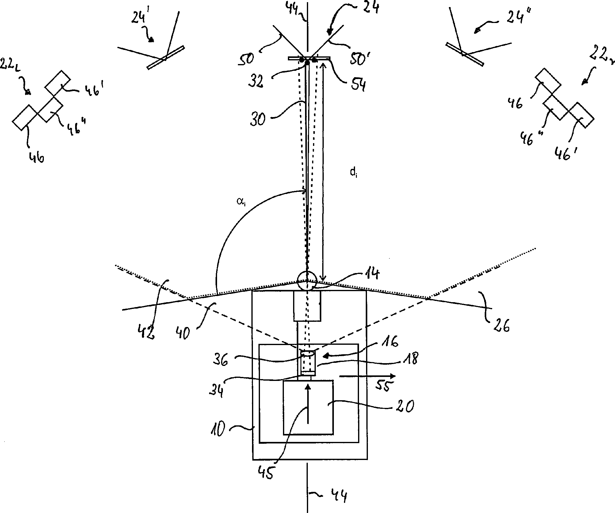
In
den
Der
Laserscanner
Der
Laserscanner
Anhand
der Laufzeit des Laserstrahlpulses wird der Abstandsbildsensorabstand
dij des Gegenstandspunktes i, im Beispiel
in
Die Menge der bei einer Abtastung erfassten Abstandsbildpunkte bildet ein Abstandsbild im Sinne der vorliegenden Anmeldung.The Set the amount of distance pixels acquired during a scan a distance image in the sense of the present application.
Der
Laserscanner
Die
monokulare Videokamera
Der
CCD-Flächensensor
Von
einem Gegenstand, beispielsweise dem Kalibrierobjekt
Aus
dem Abstand von CCD-Flächensensor
Ein Überwachungsbereich
Zur
Verarbeitung der Bilder des Laserscanners
Die
ersten Kalibrierobjekte
Wie
in
Die
ebenfalls gleich ausgebildeten zweiten Kalibrierobjekte
Auf
den Kalibrierobjekten
Bei
dem im Folgenden beschriebenen Kalibrierverfahren nach einer bevorzugten
Ausführungsform der
Erfindung werden mehrere Koordinatensysteme benutzt (vgl.
Dem
Laserscanner
Der
Ursprung des Laserscannerkoordinatensystems ist gegenüber dem
Ursprung des Fahrzeugkoordinatensystems um einen Vektor sLS verschoben, der durch die Anbaulage des
Laserscanners
Entsprechend
ist der Ursprung des Kamerakoordinatensystems gegenüber dem
Ursprung des Fahrzeugkoordinatensystems um einen Vektor sV verschoben, der durch die Anbaulage der
Videokamera
Die Achsen der Koordinatensysteme des Laserscanner- bzw. Kamerakoordinatensystems sind im Allgemeinen gegenüber den entsprechenden Achsen des Fahrzeugkoordinatensystems gedreht. Mit dem Laserscannerkoordinatensystem sind in gleicher Weise auch die Abtastflächen gegenüber der Fahrzeuglängs- und -querachse gekippt. Die Orientierung wird durch Nickwinkel ϑLS und ϑV sowie Wankwinkel φLS und φV beschrieben. Weiterhin sind die Koordinatensysteme um einen Gierwinkel ψLS bzw. ψV gedreht.The axes of the coordinate systems of the laser scanner or camera coordinate system are generally rotated with respect to the corresponding axes of the vehicle coordinate system. With the laser scanner coordinate system, the scanning surfaces are tilted in the same way relative to the vehicle longitudinal and transverse axes. The orientation is described by pitch angle θ LS and θ V and roll angle φ LS and φ V. Furthermore, the coordinate systems are rotated by a yaw angle ψ LS or ψ V.
Genauer
geht das Laserscannerkoordinatensystem aus dem Fahrzeugkoordinatensystem
hervor, indem man zuerst eine Translation um den Vektor sLS durchführt,
dann nacheinander Rotationen mit dem Gierwinkel ψLS um
die verschobene z-Achse, mit dem Wankwinkel φLS um
die verschobene und gedrehte x-Achse und zuletzt mit dem Nickwinkel ϑLS um die verschobene und gedrehte y-Achse
ausführt
(vgl.
Die
Transformation eines Punktes mit Koordinaten X, Y, Z in dem Fahrzeugkoordinatensystem
in Koordinaten XLS, YLS,
ZLS kann durch eine homogene Transformation
mit einer Rotationsmatrix R mit Einträgen rmn und
dem Translationsvektor sLS mit Komponenten
sLSx, sLSy und sLSy beschrieben werden: 
Die Komponenten des Translationsvektor sLS entsprechen den Koordinaten des Ursprungs des Laserkoordinatensystems im Fahrzeugkoordinatensystem.The components of the translation vector s LS correspond to the coordinates of the origin of the laser coordinate system in the vehicle coordinate system.
Die
Rotationsmatrix R wird aus den Elementardrehmatrizen 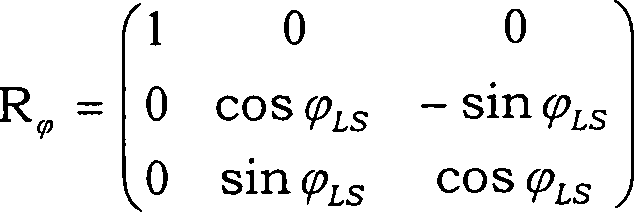
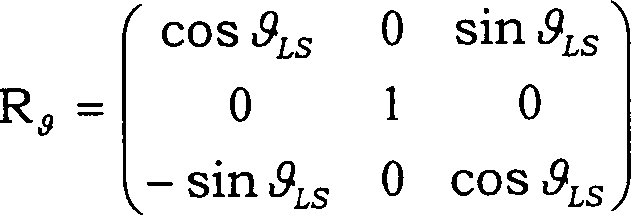
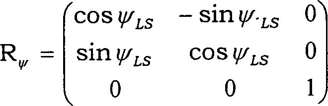
Die
Reihenfolge der Drehung kann beliebig gewählt werden, muss jedoch für die Kalibrierung
nach der Wahl beibehalten werden. Insofern definiert die Reihenfolge
genau den Nick-, Wank- und den Gierwinkel. Im Beispiel wird zuerst
um die z-Achse, dann um die x-Achse und zuletzt um die y-Achse gedreht (vgl.
Die
Ausrichtung des Laserscanner
Da bei der Kalibrierung die Koordinaten bzw. Daten im Laserscannerkoordinatensystem vorliegen, dient dieses als Ausgangspunkt. Die Koordinaten werden schrittweise ins Fahrzeugkoordinatensystem transformiert.There During calibration, the coordinates or data in the laser scanner coordinate system present, this serves as a starting point. The coordinates will be gradually transformed into the vehicle coordinate system.
Dabei wird noch ein Zwischenkoordinatensystem verwendet, das aus dem Fahrzeugkoordinatensystem durch Verschiebung um den Vektor sLS und Drehung um die verschobene z-Achse um den Gierwinkel ψLS erhalten wird. Koordinaten in diesem Koordinatensystem werden mit dem Index ZS bezeichnet.In this case, an intermediate coordinate system is used, which is obtained from the vehicle coordinate system by shifting the vector s LS and rotation about the shifted z-axis by the yaw angle ψ LS . Coordinates in this coordinate system are denoted by the index ZS.
Nick-
und Wankwinkel ergeben sich aus der Bestimmung der Orientierung
der Abtastflächen
bzw. der xLS-yLS-Ebene
des Laserscannerkoordinatensystems relativ zu dem Fahrzeug- bzw.
Zwischenkoordinatensystem. Der Gierwinkel führt zu einer Drehung einer
Bezugsrichtung des Laserscanner
Die Umrechnung der Koordinaten im Kamerakoordinatensystem in Koordinaten im Fahrzeugkoordinatensystem erfolgt analog unter Verwendung entsprechender Nick-, Wank- und Gierwinkel.The Conversion of the coordinates in the camera coordinate system into coordinates in the vehicle coordinate system is analogous using appropriate Pitch, roll and yaw angles.
Bei
dem erfindungsgemäßen Verfahren
werden Gegenstandspunkten bzw. entsprechenden, mit dem Laserscanner
Ein
Objekt im Kamerakoordinatensystem (xV, yV, zV), dessen Ursprung
im Brennpunkt des Abbildungssystems
Die
Bildpunktkoordinaten (u, v) in Pixeleinheiten eines Gegenstandspunktes
mit Koordinaten XV, YV und
ZV im Kamerakoordinatensystem lassen sich
mit Hilfe der Strahlensätze,
den in Bildpunkten angegebenen Brennweiten fu und
fv und dem Schnittpunkt (u0,
v0) der zV-Achse
mit der Mattscheibe angeben: ![]()
![]()
Die Kalibrierung wird nach einem Verfahren nach einer bevorzugten Ausführungsform der Erfindung folgendermaßen durchgeführt.The Calibration is performed by a method according to a preferred embodiment of the invention as follows carried out.
In
dem ersten Schritt werden das Fahrzeug und die Kalibierflächen, d.h.
die Kalibrierkörper
In dem folgenden Schritt werden ein Abstandsbild und ein Videobild der Szene erfasst und vorverarbeitet. Bei der Vorverarbeitung kann vorzugsweise eine Rektifikation der Videobilddaten, beispielsweise zur Beseitigung von Verzerrungen, durchgeführt werden. Das aktuelle Abstandsbild und das aktuelle Videobild werden dann zur weiteren Verwendung abgespeichert.In the following step becomes a distance image and a video image the scene captured and preprocessed. In preprocessing can preferably a rectification of the video image data, for example to eliminate distortions. The current distance image and the current video image are then saved for further use.
In
den folgenden Schritten erfolgt zunächst die Ermittlung der Orientierung
des Laserscanners
In
einem Schritt wird für
die wenigstens zwei Kalibrierobjekte
Dazu
wird für
beide Kalibrierobjekte
Aus
den Abstandsbildpunkten
Für diese Bezugspunkte Ph bzw Pv sind daher die Abstände dh und dv von dem Ursprung des Laserscannerkoordinatensystem sowie der entsprechende aus den Koordinaten in dem Laserkoordinatensystem zu berechnende Schwenkwinkel α bekannt bzw. werden aus den Abstandsbildpunkten leicht ermittelt.For these reference points P h and P v , therefore, the distances d h and d v from the origin of the laser scanner coordinate system and the corresponding one from the coordinates in the laser coordinate system are too calculating pivot angle α known or are easily determined from the distance pixels.
Der
vordere und der hintere Bezugspunkt weisen weiterhin jeweils, bedingt
durch die unterschiedlichen Neigungen der Kalibrierflächen ![]()
![]()
In
diese Gleichung geht ein vorgegebener Abstand der Kalibrierflächen
Bei dem Verfahren wird daher diese Gleichung für den Winkel β unter Verwendung der bekannten bzw. ermittelten Werte für dh, dv, H, B und h0 gelöst, was numerisch erfolgen kann. Die Werte können jedoch auch alternativ in eine analytisch gewonnene Lösung der Gleichung eingesetzt werden.In the method, therefore, this equation is solved for the angle β using the known values for d h , d v , H, B and h 0 , which can be done numerically. However, the values can also be used alternatively in an analytically obtained solution of the equation.
In
einem folgenden Schritt wird, wenn die Abtastfläche
Nach diesem Schritt gibt β' daher für das entsprechende Kalibrierobjekt die Neigung des Laserscannerkoordinatensystems entlang der Richtung α in dem Laserscannerkoordinatensystem an.To therefore, β 'gives this step for the corresponding one Calibration object the inclination of the laser scanner coordinate system along the direction α in to the laser scanner coordinate system.
Damit
sind für
die beiden Kalibrierflächen
In dem folgenden Schritt werden aus den beiden Neigungswinkeln βl' und βr' in den Richtungen αl und αr in dem Laserscannerkoordinatensystem die Winkel ϑLS und φLS zu dem Zwischenkoordinatensystem bzw. dem Fahrzeugkoordinatensystem berechnet. Wie bereits zuvor beschrieben geht das Laserkoordinatensystem aus dem Zwischenkoordinatensystem dadurch hervor, dass letzteres zunächst um den Winkel φLS um die xZS-Achse und dann um den Winkel ϑLS um die gedrehte yZS-Achse gedreht wird.In the following step, from the two inclination angles β 1 'and β r ' in the directions α 1 and α r in the laser scanner coordinate system, the angles θ LS and φ LS are calculated to the intermediate coordinate system and the vehicle coordinate system, respectively. As already described above, the laser coordinate system emerges from the intermediate coordinate system in that the latter is first rotated by the angle φ LS about the x ZS axis and then by the angle θ LS about the rotated y ZS axis.
Die
hierzu verwendete Formel kann beispielsweise folgendermaßen erhalten
werden. Es werden zwei Einheitsvektoren in dem Laserscannerkoordinatensystem
ermittelt, die in den Richtungen αl bzw. αr und parallel zu der xZS-yZS-Ebene des Zwischenkoordinatensystem, d.h.
mit den Neigungswinkeln βl' bzw. βr' gegenüber der
xLS-yLS-Ebene des
Laserscannerkoordinatensystem geneigt verlaufen. Das Vektorprodukt
aus diesen Einheitsvektoren entspricht einem Vektor in zLS-Richtung des Zwischenkoordinatensystems,
dessen Länge
gerade der Sinus des Winkels zwischen den beiden Einheitsvektoren
ist. Das in den Koordinaten des Laserscannerkoordinatensystem berechnete
Vektorprodukt wird in das Zwischenkoordinatensystem transformiert,
in dem das Ergebnis bekannt ist. Aus der Transformationsgleichung
erhält
man folgende Formel für
den Wankwinkel φLS 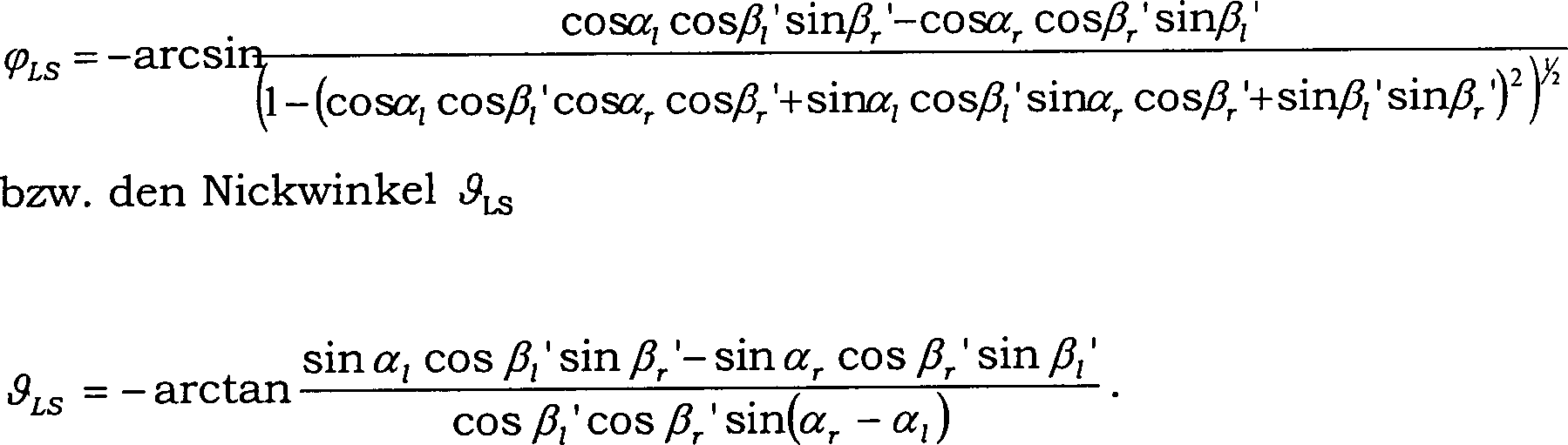
Obgleich die Werte für den Nick- und den Wankwinkel von den berechneten Schwenkwinkeln αl bzw. αr abhängen, werden zur Ermittlung im Wesentlichen Abstandsinformationen verwendet, da die Bezugspunkte im Wesentlichen auf der Basis von Abstandsinformationen ermittelt werden.Although the values for the pitch and roll angles depend on the calculated tilt angles α 1 and α r , respectively, distance information is used to determine substantially since the datum points are determined substantially on the basis of distance information.
Bei dem Verfahren werden in diese beiden Formeln nur noch die entsprechenden Werte eingesetzt.at In the process only these two formulas are replaced Values used.
In
den nächsten
Schritten wird der verbleibende Gierwinkel ψLS unter
Verwendung des auf der Fahrzeuglängsachse
Dazu
wird zunächst
ein Referenzpunkt
Der
Referenzpunkt
Die
Koordinaten des so ermittelten Referenzpunktes ![]()
![]()
Bei dem Verfahren wird diese Gleichung analog zu Bestimmung der Neigung numerisch oder analytisch für den Winkel ψLS gelöst.In the method, this equation is solved numerically or analytically for the angle ψ LS analogously to the determination of the slope.
Damit
ist die Orientierung des Laserscanners
Bei einer anderen Ausführungsform kann der tatsächliche Winkel zwischen einer auf die xLS-yLS-Ebene des Laserscannerkoordinatensystems senkrechten Ebene, in der der Winkel ε liegt, und der auf die x-y-Ebene des Fahrzeugkoordinatensystems senkrechten Ebene, in der der Winkel β ermittelt wird, genauer berücksichtigt werden. Hierzu werden ausgehend von dem nach dem ersten Ausführungsbeispiel ermittelten Wert Startwerte für den Nick- und ein Wankwinkel berechnet. Mit diesen Werten wird dann mittels bekannter trigonometrischer Beziehungen die Ausrichtung der Ebene, in der der Winkel ε liegt, und der auf die x-y-Ebene des Fahrzeugkoordinatensystems senkrechte Ebene, in der der Winkel β ermittelt wird, bestimmt. Bei bekannter Ausrichtung kann nun der Winkel ε bzw. β' in nächster Näherung bestimmt werden. Auf dieser Basis werden neue Werte für den Nick- und den Wankwinkel ermittelt. Durch Iteration, bei der die Werte für den Nick- und den Wankwinkel jeweils zu einem Endwert hin konvergieren, kann die Ausrichtung sehr genau ermittelt werden.In another embodiment, the actual angle between a plane perpendicular to the x LS -y LS plane of the laser scanner coordinate system, in which the angle ε is located, and the plane perpendicular to the xy plane of the vehicle coordinate system, in which the angle β is determined , to be considered more closely. For this purpose, starting from the value determined according to the first exemplary embodiment, start values for the pitch and roll angle are calculated. With these values, the alignment of the plane in which the angle ε is located and the plane perpendicular to the xy plane of the vehicle coordinate system, in which the angle β is determined, are then determined by means of known trigonometric relationships. With a known orientation, the angle ε or β 'can now be determined in the closest approximation. On this basis, new values for the pitch and roll angle are determined. By iteration, in which the values for the pitch and roll angles converge toward a final value, the orientation can be determined very accurately.
Auf
der Basis der bekannten Orientierung des Laserscanners
Hierzu
wird auf der Basis des mittels des Laserscanners
Diese mittels des Abstandsbildes ermittelten Lagen in dem Videobild werden mit den tatsächlich erfassten Lagen in dem Videobild in der u-v-Ebene verglichen.These be determined by the distance image detected layers in the video image with the actual detected positions in the video image in the u-v level compared.
Durch ein numerisches Optimierungsverfahren, beispielsweise das Verfahren unter Verwendung von konjugierten Gradienten, werden die Rotationswinkel für die Koordinatentransformation zwischen Fahrzeugkoordinatensystem und Kamerakoordinatensystem so optimiert, dass die mittleren quadratischen Abständen zwischen den tatsächlichen Lagen der Kalibriermerkmale in dem Videobild und den auf der Basis des Abstandsbildes vorhergesagten Lagen minimiert werden oder der Betrag der absoluten oder relativen Änderung der Rotationswinkel einen vorgegebenen Schwellwert unterschreitet.By a numerical optimization method, for example the method using conjugate gradients, the rotation angles become for the Coordinate transformation between vehicle coordinate system and Camera coordinate system optimized so that the middle square Intervals between the actual Layers of the calibration features in the video image and on the base the distance image predicted layers are minimized or the Amount of absolute or relative change in rotation angle falls below a predetermined threshold.
Im
Beispiel werden als Kalibriermerkmale die Kreuzungspunkte der Muster
auf den dritten Kalibrierflächen
Die Kreuzungspunkte können in dem Videobild einfach anhand vorgegebener Templates gefunden werden.The Intersections can in the video image can easily be found using predefined templates.
Die Kalibrierung des Laserscanners und der Videokamera können auch unabhängig voneinander durchgeführt werden.The Calibration of the laser scanner and the video camera can also independently performed from each other become.
Bei einem anderen Ausführungsbeispiel werden bei der Ermittlung des Nick- und des Wankwinkels auf der Basis der ermittelten Neigungen der virtuellen Strahlen die Koordinaten der vorderen oder hinteren Bezugspunkte in dem Laserscannerkoordinatensystem sowie die z-Komponente der Lage in dem Fahrzeugkoordinatensystem ermittelt. Auf der Basis der Koordinatentransformationen können dann der Wank- und der Nickwinkel ermittelt werden.at another embodiment are used in determining the pitch and roll angle on the Based on the determined slopes of the virtual rays the coordinates the front or rear reference points in the laser scanner coordinate system and the z component of the attitude in the vehicle coordinate system determined. On the basis of the coordinate transformations can then the roll and pitch angles are determined.
Bei
einer weiteren Ausführungsform
werden als zweite Kalibrierflächen
Zur
Ermittlung des Gierwinkels werden hier wieder unter Verwendung von
durch Abstandsbildpunkte auf den zweiten Kalibrierflächen
Bei
noch einem dritten Ausführungsbeispiel
werden nur zwei erste, quer zur Fahrzeuglängsachse voneinander beabstandete
Kalibrierflächen
verwendet, die jeweils wie die erste Kalibrierfläche
Für jede der
ersten Kalibrierflächen ![]()
![]()
Damit sind drei Punkte für die xLS-yLS-Ebene, die beiden Bezugspunkte der Kalibrierflächen und der Ursprung des Laserscannerkoordinatensystems bekannt, sodass hieraus der Nick- und der Wankwinkel ermittelt werden kann.Thus, three points are known for the x LS -y LS plane, the two reference points of the calibration surfaces and the origin of the laser scanner coordinate system, so that the pitch and roll angle can be determined therefrom.
Bei einem vierten Ausführungsbeispiel werden die Abstandsbildpunkte in zwei Abtastflächen zusammen mit den gerade beschriebenen Kalibrierflächen verwendet, wodurch die Neigung entsprechender virtueller Strahlen relativ zu der Aufstandsfläche und hieraus Nick- und Wankwinkel ermitteln lassen.at a fourth embodiment For example, the distance pixels in two scan areas will be along with the straight described calibration surfaces used, whereby the inclination of corresponding virtual rays relative to the footprint and determine the pitch and roll angles.
- 1010
- Fahrzeugvehicle
- 1212
- Aufstandsflächefootprint
- 1414
- Laserscannerlaser scanner
- 1616
- Videosystemvideo system
- 1818
- Videokameravideo camera
- 2020
- DatenverarbeitungseinrichtungData processing device
- 22l, 22r 22 l , 22 r
- erste Kalibrierobjektefirst calibration objects
- 24, 24', 24''24 24 ', 24' '
- zweite Kalibrierobjektesecond calibration objects
- 2626
- Erfassungsbereichdetection range
- 28, 28', 28'', 28'''28 28 ', 28' ', 28' ''
- Abtastflächenscanning surfaces
- 3030
- Laserstrahlbündellaser beam
- 3232
- GegenstandspunktObject point
- 3434
- CCD-FlächensensorCCD area sensor
- 3636
- Abbildungssystemimaging system
- 3838
- optische Achseoptical axis
- 4040
- VideoerfassungsbereichVideo detection range
- 4242
- Überwachungsbereichmonitoring area
- 4444
- Referenzliniereference line
- 4545
- Fahrzeuglängsachsevehicle longitudinal axis
- 46, 46', 46''46 46 ', 46' '
- erste Kalibrierflächenfirst calibration surfaces
- 4848
- FahrzeughochachseVehicle axis
- 50, 50'50, 50 '
- zweite Kalibrierflächensecond calibration surfaces
- 5252
- Kanteedge
- 5454
- dritte Kalibrierflächethird gage
- 5555
- FahrzeugquerachseVehicle transverse axis
- 5656
- virtueller Abtaststrahlvirtual scanning beam
- 5757
- AbstandsbildpunkteDistance pixels
- 5858
- Referenzpunktreference point
- 6060
- AbstandsbildpunkteDistance pixels
- 6262
- Ausgleichgeradenfit line
- 6464
- zweite Kalibrierflächensecond calibration surfaces
- 6666
- Netzlinienpower lines
Claims (23)
Priority Applications (4)
| Application Number | Priority Date | Filing Date | Title |
|---|---|---|---|
| DE102004033114A DE102004033114A1 (en) | 2004-07-08 | 2004-07-08 | Method for calibrating a distance image sensor |
| EP05013993A EP1615047A3 (en) | 2004-07-08 | 2005-06-28 | Method for calibrating an optical distance sensor mounted on a vehicle |
| JP2005198450A JP2006038843A (en) | 2004-07-08 | 2005-07-07 | Method for calibrating distance image sensor |
| US11/176,776 US20060290920A1 (en) | 2004-07-08 | 2005-07-07 | Method for the calibration of a distance image sensor |
Applications Claiming Priority (1)
| Application Number | Priority Date | Filing Date | Title |
|---|---|---|---|
| DE102004033114A DE102004033114A1 (en) | 2004-07-08 | 2004-07-08 | Method for calibrating a distance image sensor |
Publications (1)
| Publication Number | Publication Date |
|---|---|
| DE102004033114A1 true DE102004033114A1 (en) | 2006-01-26 |
Family
ID=35063138
Family Applications (1)
| Application Number | Title | Priority Date | Filing Date |
|---|---|---|---|
| DE102004033114A Withdrawn DE102004033114A1 (en) | 2004-07-08 | 2004-07-08 | Method for calibrating a distance image sensor |
Country Status (4)
| Country | Link |
|---|---|
| US (1) | US20060290920A1 (en) |
| EP (1) | EP1615047A3 (en) |
| JP (1) | JP2006038843A (en) |
| DE (1) | DE102004033114A1 (en) |
Cited By (14)
| Publication number | Priority date | Publication date | Assignee | Title |
|---|---|---|---|---|
| DE102008016188A1 (en) * | 2008-03-26 | 2009-10-01 | Robot Visual Systems Gmbh | Method for the parallel alignment of a laser scanner to a roadway |
| DE102009021483B3 (en) * | 2009-05-15 | 2011-02-24 | Fraunhofer-Gesellschaft zur Förderung der angewandten Forschung e.V. | Device and method for position and position determination |
| DE102011056948A1 (en) * | 2011-12-22 | 2013-06-27 | Jenoptik Robot Gmbh | Method for calibrating a camera to a position sensor |
| DE102017205720A1 (en) * | 2017-04-04 | 2018-10-04 | Siemens Aktiengesellschaft | Integrated calibration body |
| EP3396409A1 (en) * | 2017-04-27 | 2018-10-31 | Sick AG | Method for calibrating a camera and a laser scanner |
| US20210239813A1 (en) * | 2018-05-04 | 2021-08-05 | Valeo Schalter Und Sensoren Gmbh | Method for determining an angular position of an optoelectronic sensor, and test stand |
| WO2021170292A1 (en) | 2020-02-27 | 2021-09-02 | Sew-Eurodrive Gmbh & Co. Kg | Device and method for calibrating a laser scanner |
| US20210333378A1 (en) * | 2020-04-24 | 2021-10-28 | Crown Equipment Corporation | Industrial vehicle distance and range measurement device calibration |
| DE102021005980A1 (en) | 2021-01-14 | 2022-07-14 | Sew-Eurodrive Gmbh & Co Kg | Process for calibrating a laser scanner and technical systems |
| DE112009001833B4 (en) | 2008-08-12 | 2022-11-03 | Iee International Electronics & Engineering S.A. | 3D time-of-flight camera system and associated position/orientation calibration method |
| WO2022229062A1 (en) * | 2021-04-29 | 2022-11-03 | Valeo Schalter Und Sensoren Gmbh | Determination of a vertical position of a calibration object using a lidar-based surroundings sensor and calibration of a lidar-based surroundings sensor having a scanning plane |
| DE102022118260B3 (en) | 2022-07-21 | 2023-10-05 | Dürr Assembly Products GmbH | Method for calibrating and/or adjusting the intrinsic coordinate system of a vehicle unit relative to a coordinate system of the vehicle and vehicle test bench for carrying out the method |
| DE102023001327A1 (en) | 2022-04-14 | 2023-10-19 | Sew-Eurodrive Gmbh & Co Kg | Method for calibrating a laser scanner of a vehicle |
| DE102023004317A1 (en) | 2022-11-14 | 2024-05-16 | Sew-Eurodrive Gmbh & Co Kg | Device and method for calibrating a scanning plane of a laser scanner |
Families Citing this family (109)
| Publication number | Priority date | Publication date | Assignee | Title |
|---|---|---|---|---|
| JP4918676B2 (en) * | 2006-02-16 | 2012-04-18 | 国立大学法人 熊本大学 | Calibration apparatus and calibration method |
| USRE46672E1 (en) | 2006-07-13 | 2018-01-16 | Velodyne Lidar, Inc. | High definition LiDAR system |
| DE202007000327U1 (en) * | 2007-01-10 | 2007-04-12 | Sick Ag | Opto-electric scanner uses light transmitter whose beam is controlled so that its angle increases and photoreceptor which detects objects in area being scanned, digital camera detecting orientation of zone protected by scanner |
| DE102007046287B4 (en) * | 2007-09-27 | 2009-07-30 | Siemens Ag | Method for calibrating a sensor arrangement |
| JP5278728B2 (en) * | 2008-02-28 | 2013-09-04 | アイシン精機株式会社 | Distance image sensor calibration apparatus and calibration method |
| US7525670B1 (en) * | 2008-04-02 | 2009-04-28 | Eastman Kodak Company | Distance and orientation measurement of an object |
| AT507618B1 (en) * | 2008-11-26 | 2012-01-15 | Riegl Laser Measurement Sys | METHOD FOR DETERMINING THE RELATIVE POSITION OF A LASER SCANNER TO A REFERENCE SYSTEM |
| GB2465793A (en) * | 2008-11-28 | 2010-06-02 | Sony Corp | Estimating camera angle using extrapolated corner locations from a calibration pattern |
| DE102009013667A1 (en) * | 2009-03-24 | 2010-09-30 | Jenoptik Robot Gmbh | A method of producing a known fixed spatial relationship between a laser scanner and a digital camera for traffic surveillance |
| WO2010125492A1 (en) * | 2009-04-29 | 2010-11-04 | Koninklijke Philips Electronics N.V. | A laser diode based multiple-beam laser spot imaging system for characterization of vehicle dynamics |
| JP5702923B2 (en) * | 2009-07-27 | 2015-04-15 | 日本信号株式会社 | Distance image processing system |
| WO2011056107A1 (en) * | 2009-11-06 | 2011-05-12 | Saab Ab | Radar system and method for detecting and tracking a target |
| DE102009047324A1 (en) | 2009-12-01 | 2011-06-09 | Robert Bosch Gmbh | Hand-held device for calibrating optical sensor e.g. fixed irradiating linear detection and ranging sensor, in vehicle at e.g. workshop, has multipixel detector, and faceplate mask arranged in optical path between sensor and detector |
| CN102226696B (en) * | 2011-03-21 | 2014-01-01 | 王辉 | Measuring method of vehicle positioning ranging system for automatic coal sample acquisition system |
| DE102011006910A1 (en) * | 2011-04-07 | 2012-10-11 | Robert Bosch Gmbh | A method for determining adjustment deviations of an image acquisition chip of an optical camera and corresponding Justierprüfvorrichtungen |
| KR20130084720A (en) * | 2012-01-18 | 2013-07-26 | 삼성전기주식회사 | Apparatus and method for processing image |
| JP6111618B2 (en) * | 2012-06-29 | 2017-04-12 | 株式会社リコー | Optical axis adjusting device and optical axis adjusting method for laser device |
| DE102012217176A1 (en) * | 2012-09-24 | 2014-03-27 | Evonik Litarion Gmbh | Method for aligning a laser sensor to a measured object |
| JP6167567B2 (en) * | 2013-03-07 | 2017-07-26 | オムロン株式会社 | Imaging apparatus, rotation angle estimation method, and rotation angle estimation program |
| KR101543073B1 (en) * | 2013-07-12 | 2015-08-07 | 현대자동차주식회사 | Apparatus and Method for Driving Guide of Vehicle |
| US20150362587A1 (en) * | 2014-06-17 | 2015-12-17 | Microsoft Corporation | Lidar sensor calibration using surface pattern detection |
| JP6459239B2 (en) * | 2014-06-20 | 2019-01-30 | 船井電機株式会社 | Laser range finder |
| JP6303956B2 (en) * | 2014-09-24 | 2018-04-04 | 株式会社デンソー | Axis deviation estimation device |
| JP6413957B2 (en) * | 2014-12-26 | 2018-10-31 | 株式会社デンソー | Pitching judgment device |
| JP6475543B2 (en) * | 2015-03-31 | 2019-02-27 | 株式会社デンソー | Vehicle control apparatus and vehicle control method |
| JP6512015B2 (en) * | 2015-07-27 | 2019-05-15 | 日産自動車株式会社 | Calibration method |
| CN105068065B (en) * | 2015-07-29 | 2017-06-27 | 武汉大学 | On-orbit calibration method and system for satellite-borne laser altimeter |
| GB2540816B (en) * | 2015-07-30 | 2021-10-27 | Guidance Automation Ltd | Calibrating an Automated Guided Vehicle |
| US10557939B2 (en) | 2015-10-19 | 2020-02-11 | Luminar Technologies, Inc. | Lidar system with improved signal-to-noise ratio in the presence of solar background noise |
| CN115480252A (en) | 2015-11-05 | 2022-12-16 | 路明亮有限责任公司 | LiDAR system with improved scan speed for high-resolution depth mapping |
| CN108603758A (en) | 2015-11-30 | 2018-09-28 | 卢米诺技术公司 | The pulse laser of laser radar system and laser radar system with distribution type laser device and multiple sensor heads |
| CN105522988B (en) * | 2015-12-29 | 2018-01-30 | 同方威视技术股份有限公司 | Vehicle guidance system, the method for vehicle directional and safety check vehicle |
| US10627490B2 (en) | 2016-01-31 | 2020-04-21 | Velodyne Lidar, Inc. | Multiple pulse, LIDAR based 3-D imaging |
| JP7149256B2 (en) | 2016-03-19 | 2022-10-06 | ベロダイン ライダー ユーエスエー,インコーポレイテッド | Integrated illumination and detection for LIDAR-based 3D imaging |
| US9952317B2 (en) * | 2016-05-27 | 2018-04-24 | Uber Technologies, Inc. | Vehicle sensor calibration system |
| JP7165587B2 (en) | 2016-06-01 | 2022-11-04 | ベロダイン ライダー ユーエスエー,インコーポレイテッド | Multi-pixel scanning LIDAR |
| US9810786B1 (en) | 2017-03-16 | 2017-11-07 | Luminar Technologies, Inc. | Optical parametric oscillator for lidar system |
| US9905992B1 (en) | 2017-03-16 | 2018-02-27 | Luminar Technologies, Inc. | Self-Raman laser for lidar system |
| US9810775B1 (en) | 2017-03-16 | 2017-11-07 | Luminar Technologies, Inc. | Q-switched laser for LIDAR system |
| US9869754B1 (en) | 2017-03-22 | 2018-01-16 | Luminar Technologies, Inc. | Scan patterns for lidar systems |
| US10254388B2 (en) | 2017-03-28 | 2019-04-09 | Luminar Technologies, Inc. | Dynamically varying laser output in a vehicle in view of weather conditions |
| US10545240B2 (en) | 2017-03-28 | 2020-01-28 | Luminar Technologies, Inc. | LIDAR transmitter and detector system using pulse encoding to reduce range ambiguity |
| US10121813B2 (en) | 2017-03-28 | 2018-11-06 | Luminar Technologies, Inc. | Optical detector having a bandpass filter in a lidar system |
| US11119198B2 (en) | 2017-03-28 | 2021-09-14 | Luminar, Llc | Increasing operational safety of a lidar system |
| US10061019B1 (en) | 2017-03-28 | 2018-08-28 | Luminar Technologies, Inc. | Diffractive optical element in a lidar system to correct for backscan |
| US10732281B2 (en) | 2017-03-28 | 2020-08-04 | Luminar Technologies, Inc. | Lidar detector system having range walk compensation |
| US10139478B2 (en) | 2017-03-28 | 2018-11-27 | Luminar Technologies, Inc. | Time varying gain in an optical detector operating in a lidar system |
| US10267899B2 (en) | 2017-03-28 | 2019-04-23 | Luminar Technologies, Inc. | Pulse timing based on angle of view |
| US10209359B2 (en) | 2017-03-28 | 2019-02-19 | Luminar Technologies, Inc. | Adaptive pulse rate in a lidar system |
| US10114111B2 (en) | 2017-03-28 | 2018-10-30 | Luminar Technologies, Inc. | Method for dynamically controlling laser power |
| US10007001B1 (en) | 2017-03-28 | 2018-06-26 | Luminar Technologies, Inc. | Active short-wave infrared four-dimensional camera |
| US10969488B2 (en) | 2017-03-29 | 2021-04-06 | Luminar Holdco, Llc | Dynamically scanning a field of regard using a limited number of output beams |
| US11002853B2 (en) | 2017-03-29 | 2021-05-11 | Luminar, Llc | Ultrasonic vibrations on a window in a lidar system |
| US10191155B2 (en) | 2017-03-29 | 2019-01-29 | Luminar Technologies, Inc. | Optical resolution in front of a vehicle |
| US10976417B2 (en) | 2017-03-29 | 2021-04-13 | Luminar Holdco, Llc | Using detectors with different gains in a lidar system |
| US10663595B2 (en) | 2017-03-29 | 2020-05-26 | Luminar Technologies, Inc. | Synchronized multiple sensor head system for a vehicle |
| US11181622B2 (en) | 2017-03-29 | 2021-11-23 | Luminar, Llc | Method for controlling peak and average power through laser receiver |
| US10983213B2 (en) | 2017-03-29 | 2021-04-20 | Luminar Holdco, Llc | Non-uniform separation of detector array elements in a lidar system |
| US10641874B2 (en) | 2017-03-29 | 2020-05-05 | Luminar Technologies, Inc. | Sizing the field of view of a detector to improve operation of a lidar system |
| US10254762B2 (en) | 2017-03-29 | 2019-04-09 | Luminar Technologies, Inc. | Compensating for the vibration of the vehicle |
| US10088559B1 (en) | 2017-03-29 | 2018-10-02 | Luminar Technologies, Inc. | Controlling pulse timing to compensate for motor dynamics |
| US10401481B2 (en) | 2017-03-30 | 2019-09-03 | Luminar Technologies, Inc. | Non-uniform beam power distribution for a laser operating in a vehicle |
| US10295668B2 (en) | 2017-03-30 | 2019-05-21 | Luminar Technologies, Inc. | Reducing the number of false detections in a lidar system |
| US9989629B1 (en) | 2017-03-30 | 2018-06-05 | Luminar Technologies, Inc. | Cross-talk mitigation using wavelength switching |
| US10684360B2 (en) | 2017-03-30 | 2020-06-16 | Luminar Technologies, Inc. | Protecting detector in a lidar system using off-axis illumination |
| US10241198B2 (en) | 2017-03-30 | 2019-03-26 | Luminar Technologies, Inc. | Lidar receiver calibration |
| US11022688B2 (en) | 2017-03-31 | 2021-06-01 | Luminar, Llc | Multi-eye lidar system |
| WO2018183843A1 (en) | 2017-03-31 | 2018-10-04 | Velodyne Lidar, Inc. | Integrated lidar illumination power control |
| US20180284246A1 (en) | 2017-03-31 | 2018-10-04 | Luminar Technologies, Inc. | Using Acoustic Signals to Modify Operation of a Lidar System |
| US10677897B2 (en) | 2017-04-14 | 2020-06-09 | Luminar Technologies, Inc. | Combining lidar and camera data |
| WO2018208843A1 (en) | 2017-05-08 | 2018-11-15 | Velodyne Lidar, Inc. | Lidar data acquisition and control |
| US10211593B1 (en) | 2017-10-18 | 2019-02-19 | Luminar Technologies, Inc. | Optical amplifier with multi-wavelength pumping |
| US10451716B2 (en) | 2017-11-22 | 2019-10-22 | Luminar Technologies, Inc. | Monitoring rotation of a mirror in a lidar system |
| US10663585B2 (en) | 2017-11-22 | 2020-05-26 | Luminar Technologies, Inc. | Manufacturing a balanced polygon mirror |
| US11294041B2 (en) * | 2017-12-08 | 2022-04-05 | Velodyne Lidar Usa, Inc. | Systems and methods for improving detection of a return signal in a light ranging and detection system |
| CN109917194A (en) * | 2017-12-13 | 2019-06-21 | 清华四川能源互联网研究院 | A kind of automatic laser range calibration external member for wireless charging test macro |
| US10578720B2 (en) | 2018-04-05 | 2020-03-03 | Luminar Technologies, Inc. | Lidar system with a polygon mirror and a noise-reducing feature |
| US11029406B2 (en) | 2018-04-06 | 2021-06-08 | Luminar, Llc | Lidar system with AlInAsSb avalanche photodiode |
| US10348051B1 (en) | 2018-05-18 | 2019-07-09 | Luminar Technologies, Inc. | Fiber-optic amplifier |
| CN109084738B (en) * | 2018-07-06 | 2021-09-17 | 上海宾通智能科技有限公司 | Height-adjustable calibration system and calibration method |
| US10591601B2 (en) | 2018-07-10 | 2020-03-17 | Luminar Technologies, Inc. | Camera-gated lidar system |
| US10943367B1 (en) | 2018-07-11 | 2021-03-09 | Waymo Llc | Calibration of detection system to vehicle using a mirror |
| US10627516B2 (en) | 2018-07-19 | 2020-04-21 | Luminar Technologies, Inc. | Adjustable pulse characteristics for ground detection in lidar systems |
| US10551501B1 (en) | 2018-08-09 | 2020-02-04 | Luminar Technologies, Inc. | Dual-mode lidar system |
| US10340651B1 (en) | 2018-08-21 | 2019-07-02 | Luminar Technologies, Inc. | Lidar system with optical trigger |
| US11971507B2 (en) | 2018-08-24 | 2024-04-30 | Velodyne Lidar Usa, Inc. | Systems and methods for mitigating optical crosstalk in a light ranging and detection system |
| US10712434B2 (en) | 2018-09-18 | 2020-07-14 | Velodyne Lidar, Inc. | Multi-channel LIDAR illumination driver |
| US11082010B2 (en) | 2018-11-06 | 2021-08-03 | Velodyne Lidar Usa, Inc. | Systems and methods for TIA base current detection and compensation |
| CN109375628A (en) * | 2018-11-28 | 2019-02-22 | 南京工程学院 | A navigation method for substation inspection robot using laser orientation and radio frequency positioning |
| CN109597037B (en) * | 2018-11-29 | 2023-06-16 | 惠州华阳通用电子有限公司 | Radar calibration method and device |
| JP7056540B2 (en) * | 2018-12-18 | 2022-04-19 | 株式会社デンソー | Sensor calibration method and sensor calibration device |
| US11885958B2 (en) | 2019-01-07 | 2024-01-30 | Velodyne Lidar Usa, Inc. | Systems and methods for a dual axis resonant scanning mirror |
| US12061263B2 (en) | 2019-01-07 | 2024-08-13 | Velodyne Lidar Usa, Inc. | Systems and methods for a configurable sensor system |
| US11774561B2 (en) | 2019-02-08 | 2023-10-03 | Luminar Technologies, Inc. | Amplifier input protection circuits |
| CN109917345B (en) * | 2019-05-05 | 2020-07-10 | 北京无线电测量研究所 | Method and device for calibrating directional sensitivity of monopulse radar |
| EP3742191A1 (en) * | 2019-05-24 | 2020-11-25 | Helmut Fischer GmbH | Terahertz measuring device and method of operating a terahertz measuring device |
| US10613203B1 (en) | 2019-07-01 | 2020-04-07 | Velodyne Lidar, Inc. | Interference mitigation for light detection and ranging |
| DE102019117821A1 (en) * | 2019-07-02 | 2021-01-07 | Valeo Schalter Und Sensoren Gmbh | Calibration of an active optical sensor system using a calibration target |
| US10726579B1 (en) | 2019-11-13 | 2020-07-28 | Honda Motor Co., Ltd. | LiDAR-camera calibration |
| DE102020007645A1 (en) * | 2020-04-03 | 2021-10-07 | Daimler Ag | Method for calibrating a lidar sensor |
| WO2022011127A1 (en) * | 2020-07-08 | 2022-01-13 | Crown Equipment Corporation | Industrial vehicle distance and range measurement device calibration |
| DE102020211483A1 (en) * | 2020-09-14 | 2022-03-17 | Robert Bosch Gesellschaft mit beschränkter Haftung | Method for testing a sensor system of a motor vehicle |
| CN112379330B (en) * | 2020-11-27 | 2023-03-10 | 浙江同善人工智能技术有限公司 | Multi-robot cooperative 3D sound source identification and positioning method |
| CN112880592B (en) * | 2021-01-20 | 2022-03-04 | 湘潭大学 | Inclination calibration method of numerical control turntable center based on mandrel |
| CN113341401B (en) * | 2021-07-12 | 2024-10-11 | 广州小鹏自动驾驶科技有限公司 | Vehicle-mounted laser radar calibration method and device, vehicle and storage medium |
| JP7782208B2 (en) * | 2021-10-29 | 2025-12-09 | オムロン株式会社 | Distance Measurement System |
| CN114459423B (en) * | 2022-01-24 | 2023-06-13 | 长江大学 | Method for monocular measuring and calculating distance of navigation ship |
| US12462428B2 (en) * | 2023-06-05 | 2025-11-04 | GM Global Technology Operations LLC | Sensor angular alignment |
| CN117119324B (en) * | 2023-08-24 | 2024-03-08 | 合肥埃科光电科技股份有限公司 | Multi-area array sensor camera and installation position adjusting method and device thereof |
Citations (4)
| Publication number | Priority date | Publication date | Assignee | Title |
|---|---|---|---|---|
| DE19902287A1 (en) * | 1999-01-21 | 2000-07-27 | Volkswagen Ag | Methods for automatic adjustment of laser scanner sensor whose alignment may be altered using adjustable suspension; keeps suspension until extreme or defined value is obtained for the reflected radiation |
| DE10116278A1 (en) * | 2001-03-31 | 2002-10-02 | Volkswagen Ag | Adjustment and alignment method of separation or distance sensors on any motor vehicle using an array of reference markers arranged around the vehicle at varying angular positions |
| DE10143060A1 (en) * | 2001-09-03 | 2003-03-20 | Sick Ag | Vehicle laser scanner transmits wide beam front towards moving deflector, causing reflective front to adopt various orientations in scanned space |
| DE10217294A1 (en) * | 2002-04-18 | 2003-11-06 | Sick Ag | sensor orientation |
Family Cites Families (15)
| Publication number | Priority date | Publication date | Assignee | Title |
|---|---|---|---|---|
| DE3903801A1 (en) * | 1989-02-09 | 1990-08-16 | Diehl Gmbh & Co | METHOD FOR ALIGNING A RADAR SYSTEM TO A TARGET |
| US5525883A (en) * | 1994-07-08 | 1996-06-11 | Sara Avitzour | Mobile robot location determination employing error-correcting distributed landmarks |
| JP3734342B2 (en) * | 1997-07-29 | 2006-01-11 | 富士通テン株式会社 | Radar sensor axis alignment device |
| JP3462740B2 (en) * | 1998-01-06 | 2003-11-05 | 株式会社日立製作所 | Axis adjustment method for automotive radar |
| JP3630077B2 (en) * | 2000-06-09 | 2005-03-16 | 日産自動車株式会社 | Center axis detection method and apparatus for vehicular radar |
| JP3802339B2 (en) * | 2000-12-08 | 2006-07-26 | オムロン株式会社 | Axis adjustment method for rangefinder |
| JP3733863B2 (en) * | 2001-02-02 | 2006-01-11 | 株式会社日立製作所 | Radar equipment |
| US7061628B2 (en) * | 2001-06-27 | 2006-06-13 | Southwest Research Institute | Non-contact apparatus and method for measuring surface profile |
| JP3903752B2 (en) * | 2001-07-31 | 2007-04-11 | オムロン株式会社 | Object detection apparatus and method |
| JP3788337B2 (en) * | 2001-12-12 | 2006-06-21 | 株式会社村田製作所 | Radar module optical axis measurement method, optical axis adjustment method, and radar module |
| JP3626732B2 (en) * | 2002-02-21 | 2005-03-09 | 本田技研工業株式会社 | Detection axis adjustment method for object detection means |
| JP3708510B2 (en) * | 2002-08-26 | 2005-10-19 | 本田技研工業株式会社 | In-vehicle radar and in-vehicle camera aiming and inspection system |
| WO2004027347A1 (en) * | 2002-09-17 | 2004-04-01 | Snap-On Technologies, Inc. | Apparatus for use with a 3d image wheel aligner for facilitating adjustment of an adaptive cruise control sensor on a motor vehicle |
| JP2004184331A (en) * | 2002-12-05 | 2004-07-02 | Denso Corp | Object recognition apparatus for motor vehicle |
| US6927699B2 (en) * | 2002-12-05 | 2005-08-09 | Denso Corporation | Object recognition apparatus for vehicle, and inter-vehicle distance control unit |
-
2004
- 2004-07-08 DE DE102004033114A patent/DE102004033114A1/en not_active Withdrawn
-
2005
- 2005-06-28 EP EP05013993A patent/EP1615047A3/en not_active Withdrawn
- 2005-07-07 JP JP2005198450A patent/JP2006038843A/en active Pending
- 2005-07-07 US US11/176,776 patent/US20060290920A1/en not_active Abandoned
Patent Citations (4)
| Publication number | Priority date | Publication date | Assignee | Title |
|---|---|---|---|---|
| DE19902287A1 (en) * | 1999-01-21 | 2000-07-27 | Volkswagen Ag | Methods for automatic adjustment of laser scanner sensor whose alignment may be altered using adjustable suspension; keeps suspension until extreme or defined value is obtained for the reflected radiation |
| DE10116278A1 (en) * | 2001-03-31 | 2002-10-02 | Volkswagen Ag | Adjustment and alignment method of separation or distance sensors on any motor vehicle using an array of reference markers arranged around the vehicle at varying angular positions |
| DE10143060A1 (en) * | 2001-09-03 | 2003-03-20 | Sick Ag | Vehicle laser scanner transmits wide beam front towards moving deflector, causing reflective front to adopt various orientations in scanned space |
| DE10217294A1 (en) * | 2002-04-18 | 2003-11-06 | Sick Ag | sensor orientation |
Cited By (22)
| Publication number | Priority date | Publication date | Assignee | Title |
|---|---|---|---|---|
| DE102008016188A1 (en) * | 2008-03-26 | 2009-10-01 | Robot Visual Systems Gmbh | Method for the parallel alignment of a laser scanner to a roadway |
| DE112009001833B4 (en) | 2008-08-12 | 2022-11-03 | Iee International Electronics & Engineering S.A. | 3D time-of-flight camera system and associated position/orientation calibration method |
| DE102009021483B3 (en) * | 2009-05-15 | 2011-02-24 | Fraunhofer-Gesellschaft zur Förderung der angewandten Forschung e.V. | Device and method for position and position determination |
| DE102011056948A1 (en) * | 2011-12-22 | 2013-06-27 | Jenoptik Robot Gmbh | Method for calibrating a camera to a position sensor |
| DE102017205720A1 (en) * | 2017-04-04 | 2018-10-04 | Siemens Aktiengesellschaft | Integrated calibration body |
| WO2018184825A1 (en) | 2017-04-04 | 2018-10-11 | Siemens Mobility GmbH | Integrated calibration element |
| EP3396409A1 (en) * | 2017-04-27 | 2018-10-31 | Sick AG | Method for calibrating a camera and a laser scanner |
| DE102017109039A1 (en) * | 2017-04-27 | 2018-10-31 | Sick Ag | Method for calibrating a camera and a laser scanner |
| US10643349B2 (en) | 2017-04-27 | 2020-05-05 | Sick Ag | Method of calibrating a camera and a laser scanner |
| US20210239813A1 (en) * | 2018-05-04 | 2021-08-05 | Valeo Schalter Und Sensoren Gmbh | Method for determining an angular position of an optoelectronic sensor, and test stand |
| DE102021000474A1 (en) | 2020-02-27 | 2021-09-02 | Sew-Eurodrive Gmbh & Co Kg | Device and method for calibrating a laser scanner |
| WO2021170292A1 (en) | 2020-02-27 | 2021-09-02 | Sew-Eurodrive Gmbh & Co. Kg | Device and method for calibrating a laser scanner |
| US20210333378A1 (en) * | 2020-04-24 | 2021-10-28 | Crown Equipment Corporation | Industrial vehicle distance and range measurement device calibration |
| US11802948B2 (en) * | 2020-04-24 | 2023-10-31 | Crown Equipment Corporation | Industrial vehicle distance and range measurement device calibration |
| US12169257B2 (en) * | 2020-04-24 | 2024-12-17 | Crown Equipment Corporation | Industrial vehicle distance and range measurement device calibration |
| DE102021005980A1 (en) | 2021-01-14 | 2022-07-14 | Sew-Eurodrive Gmbh & Co Kg | Process for calibrating a laser scanner and technical systems |
| WO2022152463A1 (en) | 2021-01-14 | 2022-07-21 | Sew-Eurodrive Gmbh & Co. Kg | Method for calibrating a laser scanner, and technical apparatus |
| WO2022229062A1 (en) * | 2021-04-29 | 2022-11-03 | Valeo Schalter Und Sensoren Gmbh | Determination of a vertical position of a calibration object using a lidar-based surroundings sensor and calibration of a lidar-based surroundings sensor having a scanning plane |
| DE102023001327A1 (en) | 2022-04-14 | 2023-10-19 | Sew-Eurodrive Gmbh & Co Kg | Method for calibrating a laser scanner of a vehicle |
| DE102022118260B3 (en) | 2022-07-21 | 2023-10-05 | Dürr Assembly Products GmbH | Method for calibrating and/or adjusting the intrinsic coordinate system of a vehicle unit relative to a coordinate system of the vehicle and vehicle test bench for carrying out the method |
| DE102023004317A1 (en) | 2022-11-14 | 2024-05-16 | Sew-Eurodrive Gmbh & Co Kg | Device and method for calibrating a scanning plane of a laser scanner |
| WO2024104757A1 (en) | 2022-11-14 | 2024-05-23 | Sew-Eurodrive Gmbh & Co Kg | Device and method for calibrating a scanning plane of a laser scanner |
Also Published As
| Publication number | Publication date |
|---|---|
| EP1615047A3 (en) | 2006-03-29 |
| JP2006038843A (en) | 2006-02-09 |
| US20060290920A1 (en) | 2006-12-28 |
| EP1615047A2 (en) | 2006-01-11 |
Similar Documents
| Publication | Publication Date | Title |
|---|---|---|
| DE102004033114A1 (en) | Method for calibrating a distance image sensor | |
| DE602005004365T2 (en) | Image processing system for automotive applications | |
| DE69428686T2 (en) | IMAGING DEVICE AND METHOD FOR DETERMINING FOCUS INFORMATION | |
| EP1836455B1 (en) | Method and geodetic device for surveying at least one target | |
| EP0396867B1 (en) | Navigation procedure | |
| DE69826753T2 (en) | Optical profile sensor | |
| DE19757840C1 (en) | Optical object detection and range measuring device for autonomous vehicle | |
| EP1418444B1 (en) | Method for determining the yaw rate of a vehicle | |
| DE112010000019T5 (en) | Method for optically scanning and measuring an environment | |
| EP1460454B1 (en) | Method for combined processing of high resolution images and video images | |
| EP2234081B1 (en) | Method for producing a known fixed spatial relationship between a laser scanner and a digital camera for traffic monitoring | |
| EP2609395B1 (en) | Tilt sensor for a device and method for determining the tilt of a device | |
| WO2002103385A1 (en) | Method for preparing image information | |
| DE102010012811B4 (en) | Method for measuring speeds and associating the measured speeds with appropriate vehicles by collecting and merging object tracking data and image tracking data | |
| EP1173749A2 (en) | Image editing for preparing a texture analysis | |
| DE102004018813A1 (en) | Method for detecting and / or tracking objects | |
| DE60201849T2 (en) | Imaging system, program for controlling the image data of this system, method for correcting distortions of recorded images of this system and recording medium for storing this method | |
| DE102008031784A1 (en) | Method and apparatus for distortion correction and image enhancement of a vehicle rearview system | |
| EP3642560B1 (en) | System, method and marker for the determination of the position of a movable object in space | |
| DE102019134324A1 (en) | A method of measuring the topography of an environment | |
| DE69825525T2 (en) | Device for creating an image and method and device for distance measurement | |
| DE10148064A1 (en) | Detecting and tracking objects involves weighting current measurement value contributions, estimates and/or measurements for previous iteration depending on quality value for measurement | |
| DE10154861A1 (en) | Localizing system for objects uses transmitter for pulsed emission of laser beams and receiver with sensor to pick up reflected beam pulses and to analyze them regarding their execution time | |
| WO2013124056A1 (en) | Device for non-contact temperature measurement and temperature measurement method | |
| DE112015002764B4 (en) | Mounting angle adjustment method and mounting angle detection device for on-board camera |
Legal Events
| Date | Code | Title | Description |
|---|---|---|---|
| OM8 | Search report available as to paragraph 43 lit. 1 sentence 1 patent law | ||
| R005 | Application deemed withdrawn due to failure to request examination |
Effective date: 20110709 |