US10295668B2 - Reducing the number of false detections in a lidar system - Google Patents
Reducing the number of false detections in a lidar system Download PDFInfo
- Publication number
- US10295668B2 US10295668B2 US15/843,652 US201715843652A US10295668B2 US 10295668 B2 US10295668 B2 US 10295668B2 US 201715843652 A US201715843652 A US 201715843652A US 10295668 B2 US10295668 B2 US 10295668B2
- Authority
- US
- United States
- Prior art keywords
- lidar system
- pulse
- signature
- laser
- ranging pulse
- Prior art date
- Legal status (The legal status is an assumption and is not a legal conclusion. Google has not performed a legal analysis and makes no representation as to the accuracy of the status listed.)
- Active
Links
Images


Classifications
-
- G01S17/102—
-
- G—PHYSICS
- G01—MEASURING; TESTING
- G01S—RADIO DIRECTION-FINDING; RADIO NAVIGATION; DETERMINING DISTANCE OR VELOCITY BY USE OF RADIO WAVES; LOCATING OR PRESENCE-DETECTING BY USE OF THE REFLECTION OR RERADIATION OF RADIO WAVES; ANALOGOUS ARRANGEMENTS USING OTHER WAVES
- G01S17/00—Systems using the reflection or reradiation of electromagnetic waves other than radio waves, e.g. lidar systems
- G01S17/02—Systems using the reflection of electromagnetic waves other than radio waves
- G01S17/06—Systems determining position data of a target
- G01S17/08—Systems determining position data of a target for measuring distance only
- G01S17/10—Systems determining position data of a target for measuring distance only using transmission of interrupted, pulse-modulated waves
- G01S17/26—Systems determining position data of a target for measuring distance only using transmission of interrupted, pulse-modulated waves wherein the transmitted pulses use a frequency-modulated or phase-modulated carrier wave, e.g. for pulse compression of received signals
-
- G—PHYSICS
- G01—MEASURING; TESTING
- G01S—RADIO DIRECTION-FINDING; RADIO NAVIGATION; DETERMINING DISTANCE OR VELOCITY BY USE OF RADIO WAVES; LOCATING OR PRESENCE-DETECTING BY USE OF THE REFLECTION OR RERADIATION OF RADIO WAVES; ANALOGOUS ARRANGEMENTS USING OTHER WAVES
- G01S17/00—Systems using the reflection or reradiation of electromagnetic waves other than radio waves, e.g. lidar systems
- G01S17/02—Systems using the reflection of electromagnetic waves other than radio waves
- G01S17/06—Systems determining position data of a target
- G01S17/42—Simultaneous measurement of distance and other co-ordinates
-
- G—PHYSICS
- G01—MEASURING; TESTING
- G01S—RADIO DIRECTION-FINDING; RADIO NAVIGATION; DETERMINING DISTANCE OR VELOCITY BY USE OF RADIO WAVES; LOCATING OR PRESENCE-DETECTING BY USE OF THE REFLECTION OR RERADIATION OF RADIO WAVES; ANALOGOUS ARRANGEMENTS USING OTHER WAVES
- G01S17/00—Systems using the reflection or reradiation of electromagnetic waves other than radio waves, e.g. lidar systems
- G01S17/88—Lidar systems specially adapted for specific applications
- G01S17/89—Lidar systems specially adapted for specific applications for mapping or imaging
-
- G—PHYSICS
- G01—MEASURING; TESTING
- G01S—RADIO DIRECTION-FINDING; RADIO NAVIGATION; DETERMINING DISTANCE OR VELOCITY BY USE OF RADIO WAVES; LOCATING OR PRESENCE-DETECTING BY USE OF THE REFLECTION OR RERADIATION OF RADIO WAVES; ANALOGOUS ARRANGEMENTS USING OTHER WAVES
- G01S17/00—Systems using the reflection or reradiation of electromagnetic waves other than radio waves, e.g. lidar systems
- G01S17/88—Lidar systems specially adapted for specific applications
- G01S17/93—Lidar systems specially adapted for specific applications for anti-collision purposes
- G01S17/931—Lidar systems specially adapted for specific applications for anti-collision purposes of land vehicles
-
- G—PHYSICS
- G01—MEASURING; TESTING
- G01S—RADIO DIRECTION-FINDING; RADIO NAVIGATION; DETERMINING DISTANCE OR VELOCITY BY USE OF RADIO WAVES; LOCATING OR PRESENCE-DETECTING BY USE OF THE REFLECTION OR RERADIATION OF RADIO WAVES; ANALOGOUS ARRANGEMENTS USING OTHER WAVES
- G01S7/00—Details of systems according to groups G01S13/00, G01S15/00, G01S17/00
- G01S7/48—Details of systems according to groups G01S13/00, G01S15/00, G01S17/00 of systems according to group G01S17/00
- G01S7/481—Constructional features, e.g. arrangements of optical elements
- G01S7/4811—Constructional features, e.g. arrangements of optical elements common to transmitter and receiver
- G01S7/4812—Constructional features, e.g. arrangements of optical elements common to transmitter and receiver transmitted and received beams following a coaxial path
-
- G—PHYSICS
- G01—MEASURING; TESTING
- G01S—RADIO DIRECTION-FINDING; RADIO NAVIGATION; DETERMINING DISTANCE OR VELOCITY BY USE OF RADIO WAVES; LOCATING OR PRESENCE-DETECTING BY USE OF THE REFLECTION OR RERADIATION OF RADIO WAVES; ANALOGOUS ARRANGEMENTS USING OTHER WAVES
- G01S7/00—Details of systems according to groups G01S13/00, G01S15/00, G01S17/00
- G01S7/48—Details of systems according to groups G01S13/00, G01S15/00, G01S17/00 of systems according to group G01S17/00
- G01S7/481—Constructional features, e.g. arrangements of optical elements
- G01S7/4814—Constructional features, e.g. arrangements of optical elements of transmitters alone
-
- G—PHYSICS
- G01—MEASURING; TESTING
- G01S—RADIO DIRECTION-FINDING; RADIO NAVIGATION; DETERMINING DISTANCE OR VELOCITY BY USE OF RADIO WAVES; LOCATING OR PRESENCE-DETECTING BY USE OF THE REFLECTION OR RERADIATION OF RADIO WAVES; ANALOGOUS ARRANGEMENTS USING OTHER WAVES
- G01S7/00—Details of systems according to groups G01S13/00, G01S15/00, G01S17/00
- G01S7/48—Details of systems according to groups G01S13/00, G01S15/00, G01S17/00 of systems according to group G01S17/00
- G01S7/481—Constructional features, e.g. arrangements of optical elements
- G01S7/4816—Constructional features, e.g. arrangements of optical elements of receivers alone
-
- G—PHYSICS
- G01—MEASURING; TESTING
- G01S—RADIO DIRECTION-FINDING; RADIO NAVIGATION; DETERMINING DISTANCE OR VELOCITY BY USE OF RADIO WAVES; LOCATING OR PRESENCE-DETECTING BY USE OF THE REFLECTION OR RERADIATION OF RADIO WAVES; ANALOGOUS ARRANGEMENTS USING OTHER WAVES
- G01S7/00—Details of systems according to groups G01S13/00, G01S15/00, G01S17/00
- G01S7/48—Details of systems according to groups G01S13/00, G01S15/00, G01S17/00 of systems according to group G01S17/00
- G01S7/481—Constructional features, e.g. arrangements of optical elements
- G01S7/4817—Constructional features, e.g. arrangements of optical elements relating to scanning
-
- G—PHYSICS
- G01—MEASURING; TESTING
- G01S—RADIO DIRECTION-FINDING; RADIO NAVIGATION; DETERMINING DISTANCE OR VELOCITY BY USE OF RADIO WAVES; LOCATING OR PRESENCE-DETECTING BY USE OF THE REFLECTION OR RERADIATION OF RADIO WAVES; ANALOGOUS ARRANGEMENTS USING OTHER WAVES
- G01S7/00—Details of systems according to groups G01S13/00, G01S15/00, G01S17/00
- G01S7/48—Details of systems according to groups G01S13/00, G01S15/00, G01S17/00 of systems according to group G01S17/00
- G01S7/483—Details of pulse systems
- G01S7/484—Transmitters
-
- G—PHYSICS
- G01—MEASURING; TESTING
- G01S—RADIO DIRECTION-FINDING; RADIO NAVIGATION; DETERMINING DISTANCE OR VELOCITY BY USE OF RADIO WAVES; LOCATING OR PRESENCE-DETECTING BY USE OF THE REFLECTION OR RERADIATION OF RADIO WAVES; ANALOGOUS ARRANGEMENTS USING OTHER WAVES
- G01S7/00—Details of systems according to groups G01S13/00, G01S15/00, G01S17/00
- G01S7/48—Details of systems according to groups G01S13/00, G01S15/00, G01S17/00 of systems according to group G01S17/00
- G01S7/483—Details of pulse systems
- G01S7/486—Receivers
- G01S7/4865—Time delay measurement, e.g. time-of-flight measurement, time of arrival measurement or determining the exact position of a peak
-
- G—PHYSICS
- G01—MEASURING; TESTING
- G01S—RADIO DIRECTION-FINDING; RADIO NAVIGATION; DETERMINING DISTANCE OR VELOCITY BY USE OF RADIO WAVES; LOCATING OR PRESENCE-DETECTING BY USE OF THE REFLECTION OR RERADIATION OF RADIO WAVES; ANALOGOUS ARRANGEMENTS USING OTHER WAVES
- G01S17/00—Systems using the reflection or reradiation of electromagnetic waves other than radio waves, e.g. lidar systems
- G01S17/02—Systems using the reflection of electromagnetic waves other than radio waves
- G01S17/06—Systems determining position data of a target
- G01S17/08—Systems determining position data of a target for measuring distance only
- G01S17/32—Systems determining position data of a target for measuring distance only using transmission of continuous waves, whether amplitude-, frequency-, or phase-modulated, or unmodulated
- G01S17/36—Systems determining position data of a target for measuring distance only using transmission of continuous waves, whether amplitude-, frequency-, or phase-modulated, or unmodulated with phase comparison between the received signal and the contemporaneously transmitted signal
-
- G—PHYSICS
- G01—MEASURING; TESTING
- G01S—RADIO DIRECTION-FINDING; RADIO NAVIGATION; DETERMINING DISTANCE OR VELOCITY BY USE OF RADIO WAVES; LOCATING OR PRESENCE-DETECTING BY USE OF THE REFLECTION OR RERADIATION OF RADIO WAVES; ANALOGOUS ARRANGEMENTS USING OTHER WAVES
- G01S17/00—Systems using the reflection or reradiation of electromagnetic waves other than radio waves, e.g. lidar systems
- G01S17/87—Combinations of systems using electromagnetic waves other than radio waves
Definitions
- This disclosure generally relates to lidar systems and, more particularly, using certain types of lasers in a lidar system.
- a lidar system includes a light source and an optical receiver.
- the light source can be, for example, a laser which emits light having a particular operating wavelength.
- the operating wavelength of a lidar system may lie, for example, in the infrared, visible, or ultraviolet portions of the electromagnetic spectrum.
- the light source emits light toward a target which then scatters the light. Some of the scattered light is received back at the receiver.
- the system determines the distance to the target based on one or more characteristics associated with the returned light. For example, the system may determine the distance to the target based on the time of flight of a returned light pulse.
- the receiver of a lidar system sometimes may detect light signals emitted by another lidar system or another source.
- the lidar system can generate readings that include ranging errors.
- a lidar system configured to collect information with fewer false detections of return pulses includes a light source, a scanner, and a receiver.
- the light source includes a laser and is configured to emit a ranging pulse including a sequence of fast pulses generated by the laser. Time intervals between the fast pulses within the ranging pulse at least partially define a signature of the ranging pulse.
- the scanner is configured to direct the ranging pulse according to a scan direction to illuminate an instantaneous field of view (FOV) of the light source at a time when the ranging pulse is emitted.
- FOV instantaneous field of view
- the receiver is configured to detect light scattered by remote targets and includes a detector element configured to detect a light signal and a signature detection circuitry configured to determine whether the detected light signal contains or corresponds to the signature of the emitted ranging pulse.
- the lidar system is configured to generate a pixel value corresponding to the instantaneous FOV of the light source based on the detected light signal if the detected light signal contains or corresponds to the signature of the emitted ranging pulse.
- the method includes generating, using a laser, a ranging pulse including a sequence of fast pulses, with time intervals between the fast pulses within the ranging pulse at least partially defining a signature of the ranging pulse.
- the method further includes directing, using a scanner, the ranging pulse according to a scan direction to illuminate an instantaneous FOV of the light source at a time when the ranging pulse is emitted, detecting a light signal using a detector element, and determining whether the light signal contains or corresponds to the signature of the emitted ranging pulse.
- the method includes generating a pixel value corresponding to the instantaneous FOV of the light source based on the detected light signal. Otherwise, in response to determining that the light signal does not contain or correspond to the signature of the emitted ranging pulse, the method includes discarding or disregarding the detected light signal.
- a lidar system equipped with a light source that includes a mode-locked integrated external-cavity surface emitting laser (MIXSEL) configured to generate a sequence of pulses having a pseudo-random sequence.
- the lidar system further includes circuitry configured to identify a sequence of a portion of the pulse train, where the sequence specifies time intervals between respective pairs of pulses, a scanner configured to direct the portion of the pulse train as an outbound pulse to illuminate a field of view of the light source, and a receiver including at least one detector element configured to detect a light signal.
- the circuitry is further configured to determine whether the light signal includes the previously identified sequence.
- the lidar system is configured to process the detected light signal as a return of the outbound pulse scattered by a target within the field of view of the light source if the circuitry determines that the signal includes or corresponds to the previously identified sequence.
- FIG. 1 is a block diagram of an example light detection and ranging (lidar) system in which the techniques of this disclosure can be implemented;
- FIG. 2 illustrates in more detail several components that can operate in the system of FIG. 1 ;
- FIG. 3 illustrates an example configuration in which the components of FIG. 1 scan a 360-degree field of regard through a window in a rotating housing;
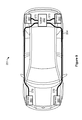
- FIG. 4 illustrates another configuration in which the components of FIG. 1 scan a 360-degree field of regard through a substantially transparent stationary housing
- FIG. 5 illustrates an example scan pattern which the lidar system of FIG. 1 can produce when identifying targets within a field of regard;
- FIG. 6 illustrates an example scan pattern which the lidar system of FIG. 1 can produce when identifying targets within a field of regard using multiple beams
- FIG. 7 schematically illustrates fields of view (FOVs) of a light source and a detector that can operate in the lidar system of FIG. 1 ;
- FIG. 8 illustrates an example configuration of the lidar system of FIG. 1 or another suitable lidar system, in which a laser is disposed away from sensor components;
- FIG. 9 illustrates an example vehicle in which the lidar system of FIG. 1 can operate
- FIG. 10 illustrates an example InGaAs avalanche photodiode which can operate in the lidar system of FIG. 1 ;
- FIG. 11 illustrates an example photodiode coupled to a pulse-detection circuit, which can operate in the lidar system of FIG. 1 .
- FIG. 12 illustrates an example light pulse made up of a sequence of energy peaks spaced apart at pseudo-random time intervals, which may be used in the lidar system of FIG. 1 ;
- FIGS. 13A and 13B are diagrams of two configurations including a MIXSEL that can be used in the lidar system of FIG. 1 ;
- FIG. 14 is a diagram of an example circuit that can be implemented in the system of FIG. 1 to identify pulses emitted by a MIXSEL operating in the lidar system of FIG. 1 ;
- FIG. 15 illustrates an example of obtaining a signature of a ranging pulse from a sequence of energy peaks spaced apart at pseudo-random time intervals emitted by a laser operating in the lidar system of FIG. 1 ;
- FIG. 16 is a flow diagram of an example method for collecting information with fewer false detections, which can be implemented in the lidar system of FIG. 1 .
- a lidar system of this disclosure can generate ranging pulses that include sequences of faster pulses, referred to here as “ultra-fast pulses” or simply “fast pulses,” where certain properties of these sequences effectively define signatures of the ranging pulses. These properties can include time intervals (e.g., time intervals between certain threshold energy levels of the faster pulses), pulse widths, or pulse amplitudes. The time intervals, pulse widths, or pulse amplitudes can be regular or pseudo-random, depending on how the laser is configured.
- the lidar system can determine whether a detected light signal corresponds to the ranging pulse which the lidar system had emitted and which a remote target scattered. The lidar system accordingly generates data with a significantly lower probability of false detection of return pulses.
- the lidar system can utilize a mode-locked laser such as a mode-locked integrated external cavity surface emitting laser (MIXSEL).
- MIXSEL mode-locked integrated external cavity surface emitting laser
- FIGS. 1-4 An example lidar system in which these techniques can be implemented is considered next with reference to FIGS. 1-4 , followed by a discussion of the techniques which the lidar system can implement to scan a field of regard and generate individual pixels ( FIGS. 5-7 ).
- An example implementation in a vehicle is then discussed with reference to FIGS. 8 and 9 .
- an example photo detector and an example pulse-detection circuit are discussed with reference to FIGS. 10 and 11 .
- Techniques for using mode-locked lasers to reduce the probability of errors in scans is discussed with reference to FIGS. 12-16 .
- FIG. 1 illustrates an example light detection and ranging (lidar) system 100 .
- the lidar system 100 may be referred to as a laser ranging system, a laser radar system, a LIDAR system, a lidar sensor, or a laser detection and ranging (LADAR or ladar) system.
- the lidar system 100 may include a light source 110 , a mirror 115 , a scanner 120 , a receiver 140 , and a controller 150 .
- the light source 110 may be, for example, a laser which emits light having a particular operating wavelength in the infrared, visible, or ultraviolet portions of the electromagnetic spectrum. As a more specific example, the light source 110 may include a laser with an operating wavelength between approximately 1.2 ⁇ m and 1.7 ⁇ m.
- the light source 110 emits an output beam of light 125 which may be continuous-wave, pulsed, or modulated in any suitable manner for a given application.
- the output beam of light 125 is directed downrange toward a remote target 130 located a distance D from the lidar system 100 and at least partially contained within a field of regard of the system 100 .
- D can be between 1 m and 1 km, for example.
- the target 130 may scatter or, in some cases, reflect at least a portion of light from the output beam 125 , and some of the scattered or reflected light may return toward the lidar system 100 .
- the scattered or reflected light is represented by input beam 135 , which passes through the scanner 120 , which may be referred to as a beam scanner, optical scanner, or laser scanner.
- the input beam 135 passes through the scanner 120 to the mirror 115 , which may be referred to as an overlap mirror, superposition mirror, or beam-combiner mirror.
- the mirror 115 in turn directs the input beam 135 to the receiver 140 .
- the input 135 may contain only a relatively small fraction of the light from the output beam 125 .
- the ratio of average power, peak power, or pulse energy of the input beam 135 to average power, peak power, or pulse energy of the output beam 125 may be approximately 10 ⁇ 1 , 10 ⁇ 2 , 10 ⁇ 3 , 10 ⁇ 4 , 10 ⁇ 5 , 10 ⁇ 6 , 10 ⁇ 7 , 10 ⁇ 8 , 10 ⁇ 9 , 10 ⁇ 10 , 10 ⁇ 11 , or 10 ⁇ 12 .
- the pulse energy of a corresponding pulse of the input beam 135 may have a pulse energy of approximately 10 nanojoules (nJ), 1 nJ, 100 picojoules (pJ), 10 pJ, 1 pJ, 100 femtojoules (fJ), 10 fJ, 1 fJ, 100 attojoules (aJ), 10 aJ, or 1 aJ.
- the output beam 125 may be referred to as a laser beam, light beam, optical beam, emitted beam, or just beam; and the input beam 135 may be referred to as a return beam, received beam, return light, received light, input light, scattered light, or reflected light.
- scattered light may refer to light that is scattered or reflected by the target 130 .
- the input beam 135 may include light from the output beam 125 that is scattered by the target 130 , light from the output beam 125 that is reflected by the target 130 , or a combination of scattered and reflected light from target 130 .
- the operating wavelength of a lidar system 100 may lie, for example, in the infrared, visible, or ultraviolet portions of the electromagnetic spectrum.
- the Sun also produces light in these wavelength ranges, and thus sunlight can act as background noise which can obscure signal light detected by the lidar system 100 .
- This solar background noise can result in false-positive detections or can otherwise corrupt measurements of the lidar system 100 , especially when the receiver 140 includes SPAD detectors (which can be highly sensitive).
- the light from the Sun that passes through the Earth's atmosphere and reaches a terrestrial-based lidar system such as the system 100 can establish an optical background noise floor for this system.
- the signal in order for a signal from the lidar system 100 to be detectable, the signal must rise above the background noise floor.
- SNR signal-to-noise
- the lidar system 100 operates at one or more wavelengths between approximately 1400 nm and approximately 1600 nm.
- the light source 110 may produce light at approximately 1550 nm.
- the lidar system 100 operates at frequencies at which atmospheric absorption is relatively low.
- the lidar system 100 can operate at wavelengths in the approximate ranges from 980 nm to 1110 nm or from 1165 nm to 1400 nm.
- the lidar system 100 operates at frequencies at which atmospheric absorption is high.
- the lidar system 100 can operate at wavelengths in the approximate ranges from 930 nm to 980 nm, from 1100 nm to 1165 nm, or from 1400 nm to 1460 nm.
- the lidar system 100 can include an eye-safe laser, or the lidar system 100 can be classified as an eye-safe laser system or laser product.
- An eye-safe laser, laser system, or laser product may refer to a system with an emission wavelength, average power, peak power, peak intensity, pulse energy, beam size, beam divergence, exposure time, or scanned output beam such that emitted light from the system presents little or no possibility of causing damage to a person's eyes.
- the light source 110 or lidar system 100 may be classified as a Class 1 laser product (as specified by the 60825-1 standard of the International Electrotechnical Commission (IEC)) or a Class I laser product (as specified by Title 21, Section 1040.10 of the United States Code of Federal Regulations (CFR)) that is safe under all conditions of normal use.
- the lidar system 100 may be classified as an eye-safe laser product (e.g., with a Class 1 or Class I classification) configured to operate at any suitable wavelength between approximately 1400 nm and approximately 2100 nm.
- the light source 110 may include a laser with an operating wavelength between approximately 1400 nm and approximately 1600 nm, and the lidar system 100 may be operated in an eye-safe manner.
- the light source 110 or the lidar system 100 may be an eye-safe laser product that includes a scanned laser with an operating wavelength between approximately 1530 nm and approximately 1560 nm.
- the lidar system 100 may be a Class 1 or Class I laser product that includes a fiber laser or solid-state laser with an operating wavelength between approximately 1400 nm and approximately 1600 nm.
- the lidar system 100 may include mode-locked laser, such as a MIXSEL. Once activated, a MIXSEL can produce a pseudo-random pulse train at a very high frequency (e.g., at 0.5 GHz to 50 GHz rate).
- a MIXSEL can be configured to have direct emission at 1550 nm or 980 nm, for example.
- the receiver 140 may receive or detect photons from the input beam 135 and generate one or more representative signals. For example, the receiver 140 may generate an output electrical signal 145 that is representative of the input beam 135 . The receiver may send the electrical signal 145 to the controller 150 .
- the controller 150 may include one or more processors, an application-specific integrated circuit (ASIC), a field-programmable gate array (FPGA), and/or other suitable circuitry configured to analyze one or more characteristics of the electrical signal 145 to determine one or more characteristics of the target 130 , such as its distance downrange from the lidar system 100 . More particularly, the controller 150 may analyze the time of flight or phase modulation for the beam of light 125 transmitted by the light source 110 .
- ASIC application-specific integrated circuit
- FPGA field-programmable gate array
- the distance D from lidar system 100 to the target 130 may be referred to as a distance, depth, or range of the target 130 .
- the speed of light c refers to the speed of light in any suitable medium, such as for example in air, water, or vacuum. The speed of light in vacuum is approximately 2.9979 ⁇ 10 8 m/s, and the speed of light in air (which has a refractive index of approximately 1.0003) is approximately 2.9970 ⁇ 10 8 m/s.
- the target 130 may be located a distance D from the lidar system 100 that is less than or equal to a maximum range R MAX of the lidar system 100 .
- the maximum range R MAX (which also may be referred to as a maximum distance) of a lidar system 100 may correspond to the maximum distance over which the lidar system 100 is configured to sense or identify targets that appear in a field of regard of the lidar system 100 .
- the maximum range of lidar system 100 may be any suitable distance, such as for example, 25 m, 50 m, 100 m, 200 m, 500 m, or 1 km.
- a lidar system with a 200-m maximum range may be configured to sense or identify various targets located up to 200 m away.
- the time of flight corresponding to the maximum range is approximately 2 ⁇ R MAX /c ⁇ 1.33 ⁇ s.
- the light source 110 , the scanner 120 , and the receiver 140 may be packaged together within a single housing 155 , which may be a box, case, or enclosure that holds or contains all or part of a lidar system 100 .
- the housing 155 includes a window 157 through which the beams 125 and 135 pass.
- the lidar-system housing 155 contains the light source 110 , the overlap mirror 115 , the scanner 120 , and the receiver 140 of a lidar system 100 .
- the controller 150 may reside within the same housing 155 as the components 110 , 120 , and 140 , or the controller 150 may reside remotely from the housing.
- the housing 155 includes multiple lidar sensors, each including a respective scanner and a receiver.
- each of the multiple sensors can include a separate light source or a common light source.
- the multiple sensors can be configured to cover non-overlapping adjacent fields of regard or partially overlapping fields of regard, depending on the implementation.
- the housing 155 may be an airtight or watertight structure that prevents water vapor, liquid water, dirt, dust, or other contaminants from getting inside the housing 155 .
- the housing 155 may be filled with a dry or inert gas, such as for example dry air, nitrogen, or argon.
- the housing 155 may include one or more electrical connections for conveying electrical power or electrical signals to and/or from the housing.
- the window 157 may be made from any suitable substrate material, such as for example, glass or plastic (e.g., polycarbonate, acrylic, cyclic-olefin polymer, or cyclic-olefin copolymer).
- the window 157 may include an interior surface (surface A) and an exterior surface (surface B), and surface A or surface B may include a dielectric coating having particular reflectivity values at particular wavelengths.
- a dielectric coating (which may be referred to as a thin-film coating, interference coating, or coating) may include one or more thin-film layers of dielectric materials (e.g., SiO 2 , TiO 2 , Al 2 O 3 , Ta 2 O 5 , MgF 2 , LaF 3 , or AlF 3 ) having particular thicknesses (e.g., thickness less than 1 ⁇ m) and particular refractive indices.
- a dielectric coating may be deposited onto surface A or surface B of the window 157 using any suitable deposition technique, such as for example, sputtering or electron-beam deposition.
- the dielectric coating may have a high reflectivity at a particular wavelength or a low reflectivity at a particular wavelength.
- a high-reflectivity (HR) dielectric coating may have any suitable reflectivity value (e.g., a reflectivity greater than or equal to 80%, 90%, 95%, or 99%) at any suitable wavelength or combination of wavelengths.
- a low-reflectivity dielectric coating (which may be referred to as an anti-reflection (AR) coating) may have any suitable reflectivity value (e.g., a reflectivity less than or equal to 5%, 2%, 1%, 0.5%, or 0.2%) at any suitable wavelength or combination of wavelengths.
- a dielectric coating may be a dichroic coating with a particular combination of high or low reflectivity values at particular wavelengths.
- a dichroic coating may have a reflectivity of less than or equal to 0.5% at approximately 1550-1560 nm and a reflectivity of greater than or equal to 90% at approximately 800-1500 nm.
- surface A or surface B has a dielectric coating that is anti-reflecting at an operating wavelength of one or more light sources 110 contained within enclosure 155 .
- An AR coating on surface A and surface B may increase the amount of light at an operating wavelength of light source 110 that is transmitted through the window 157 . Additionally, an AR coating at an operating wavelength of the light source 110 may reduce the amount of incident light from output beam 125 that is reflected by the window 157 back into the housing 155 .
- each of surface A and surface B has an AR coating with reflectivity less than 0.5% at an operating wavelength of light source 110 .
- each of surface A and surface B may each have an AR coating with a reflectivity that is less than 0.5% from approximately 1547 nm to approximately 1553 nm.
- each of surface A and surface B has an AR coating with reflectivity less than 1% at the operating wavelengths of the light source 110 .
- the housing 155 encloses two sensor heads with respective light sources, the first light source emits pulses at a wavelength of approximately 1535 nm and the second light source emits pulses at a wavelength of approximately 1540 nm, then surface A and surface B may each have an AR coating with reflectivity less than 1% from approximately 1530 nm to approximately 1545 nm.
- the window 157 may have an optical transmission that is greater than any suitable value for one or more wavelengths of one or more light sources 110 contained within the housing 155 .
- the window 157 may have an optical transmission of greater than or equal to 70%, 80%, 90%, 95%, or 99% at a wavelength of light source 110 .
- the window 157 can transmit greater than or equal to 95% of light at an operating wavelength of the light source 110 .
- the window 157 transmits greater than or equal to 90% of light at the operating wavelengths of the light sources enclosed within the housing 155 .
- Surface A or surface B may have a dichroic coating that is anti-reflecting at one or more operating wavelengths of one or more light sources 110 and high-reflecting at wavelengths away from the one or more operating wavelengths.
- surface A may have an AR coating for an operating wavelength of the light source 110
- surface B may have a dichroic coating that is AR at the light-source operating wavelength and HR for wavelengths away from the operating wavelength.
- a coating that is HR for wavelengths away from a light-source operating wavelength may prevent most incoming light at unwanted wavelengths from being transmitted through the window 117 .
- surface A may have an AR coating with a reflectivity of less than or equal to 0.5% from approximately 1546 nm to approximately 1554 nm.
- surface B may have a dichroic coating that is AR at approximately 1546-1554 nm and HR (e.g., reflectivity of greater than or equal to 90%) at approximately 800-1500 nm and approximately 1580-1700 nm.
- Surface B of the window 157 may include a coating that is oleophobic, hydrophobic, or hydrophilic.
- a coating that is oleophobic (or, lipophobic) may repel oils (e.g., fingerprint oil or other non-polar material) from the exterior surface (surface B) of the window 157 .
- a coating that is hydrophobic may repel water from the exterior surface.
- surface B may be coated with a material that is both oleophobic and hydrophobic.
- a coating that is hydrophilic attracts water so that water may tend to wet and form a film on the hydrophilic surface (rather than forming beads of water as may occur on a hydrophobic surface).
- surface B has a hydrophilic coating
- water e.g., from rain
- the surface film of water may result in less distortion, deflection, or occlusion of an output beam 125 than a surface with a non-hydrophilic coating or a hydrophobic coating.
- the light source 110 may include a pulsed laser configured to produce or emit pulses of light with a certain pulse duration.
- the pulse duration or pulse width of the pulsed laser is approximately 10 picoseconds (ps) to 20 nanoseconds (ns).
- the light source 110 is a pulsed laser that produces pulses with a pulse duration of approximately 1-4 ns.
- the light source 110 is a pulsed laser that produces pulses at a pulse repetition frequency of approximately 100 kHz to 5 MHz or a pulse period (e.g., a time between consecutive pulses) of approximately 200 ns to 10 ⁇ s.
- the light source 110 may have a substantially constant or a variable pulse repetition frequency, depending on the implementation.
- the light source 110 may be a pulsed laser that produces pulses at a substantially constant pulse repetition frequency of approximately 640 kHz (e.g., 640,000 pulses per second), corresponding to a pulse period of approximately 1.56 ⁇ s.
- the light source 110 may have a pulse repetition frequency that can be varied from approximately 500 kHz to 3 MHz.
- a pulse of light may be referred to as an optical pulse, a light pulse, or a pulse, and a pulse repetition frequency may be referred to as a pulse rate.
- the output beam 125 may have any suitable average optical power, and the output beam 125 may include optical pulses with any suitable pulse energy or peak optical power.
- Some examples of the average power of the output beam 125 include the approximate values of 1 mW, 10 mW, 100 mW, 1 W, and 10 W.
- Example values of pulse energy of the output beam 125 include the approximate values of 0.1 ⁇ J, 1 ⁇ J, 10 ⁇ J, 100 ⁇ J, and 1 mJ.
- Examples of peak power values of pulses included in the output beam 125 are the approximate values of 10 W, 100 W, 1 kW, 5 kW, 10 kW.
- An example optical pulse with a duration of 1 ns and a pulse energy of 1 ⁇ J has a peak power of approximately 1 kW. If the pulse repetition frequency is 500 kHz, then the average power of the output beam 125 with 1- ⁇ J pulses is approximately 0.5 W, in this example.
- the light source 110 may include a laser diode, such as a Fabry-Perot laser diode, a quantum well laser, a distributed Bragg reflector (DBR) laser, a distributed feedback (DFB) laser, or a vertical-cavity surface-emitting laser (VCSEL).
- the laser diode operating in the light source 110 may be an aluminum-gallium-arsenide (AlGaAs) laser diode, an indium-gallium-arsenide (InGaAs) laser diode, or an indium-gallium-arsenide-phosphide (InGaAsP) laser diode, or any other suitable diode.
- the light source 110 includes a pulsed laser diode with a peak emission wavelength of approximately 1400-1600 nm. Further, the light source 110 may include a laser diode that is current-modulated to produce optical pulses.
- the light source 110 includes a pulsed laser diode followed by one or more optical-amplification stages.
- the light source 110 may be a fiber-laser module that includes a current-modulated laser diode with a peak wavelength of approximately 1550 nm, followed by a single-stage or a multi-stage erbium-doped fiber amplifier (EDFA).
- EDFA erbium-doped fiber amplifier
- the light source 110 may include a continuous-wave (CW) or quasi-CW laser diode followed by an external optical modulator (e.g., an electro-optic modulator), and the output of the modulator may be fed into an optical amplifier.
- CW continuous-wave
- an electro-optic modulator e.g., an electro-optic modulator
- a light source 110 that includes a laser diode followed by one or more optical-amplification stages may be referred to as a master oscillator power amplifier (MOPA) in which the laser diode acts as a master oscillator.
- MOPA master oscillator power amplifier
- the light source 110 may include a pulsed solid-state laser or a pulsed fiber laser.
- the output beam of light 125 emitted by the light source 110 is a collimated optical beam with any suitable beam divergence, such as a divergence of approximately 0.1 to 3.0 milliradian (mrad). Divergence of the output beam 125 may refer to an angular measure of an increase in beam size (e.g., a beam radius or beam diameter) as the output beam 125 travels away from the light source 110 or the lidar system 100 .
- the output beam 125 may have a substantially circular cross section with a beam divergence characterized by a single divergence value.
- the output beam 125 with a circular cross section and a divergence of 1 mrad may have a beam diameter or spot size of approximately 10 cm at a distance of 100 m from the lidar system 100 .
- the output beam 125 may be an astigmatic beam or may have a substantially elliptical cross section and may be characterized by two divergence values.
- the output beam 125 may have a fast axis and a slow axis, where the fast-axis divergence is greater than the slow-axis divergence.
- the output beam 125 may be an astigmatic beam with a fast-axis divergence of 2 mrad and a slow-axis divergence of 0.5 mrad.
- the output beam of light 125 emitted by light source 110 may be unpolarized or randomly polarized, may have no specific or fixed polarization (e.g., the polarization may vary with time), or may have a particular polarization (e.g., the output beam 125 may be linearly polarized, elliptically polarized, or circularly polarized).
- the light source 110 may produce linearly polarized light
- the lidar system 100 may include a quarter-wave plate that converts this linearly polarized light into circularly polarized light.
- the lidar system 100 may transmit the circularly polarized light as the output beam 125 , and receive the input beam 135 , which may be substantially or at least partially circularly polarized in the same manner as the output beam 125 (e.g., if the output beam 125 is right-hand circularly polarized, then the input beam 135 may also be right-hand circularly polarized).
- the input beam 135 may pass through the same quarter-wave plate (or a different quarter-wave plate), resulting in the input beam 135 being converted to linearly polarized light which is orthogonally polarized (e.g., polarized at a right angle) with respect to the linearly polarized light produced by light source 110 .
- the lidar system 100 may employ polarization-diversity detection where two polarization components are detected separately.
- the output beam 125 may be linearly polarized, and the lidar system 100 may split the input beam 135 into two polarization components (e.g., s-polarization and p-polarization) which are detected separately by two photodiodes (e.g., a balanced photoreceiver that includes two photodiodes).
- two polarization components e.g., s-polarization and p-polarization
- two photodiodes e.g., a balanced photoreceiver that includes two photodiodes.
- the output beam 125 and input beam 135 may be substantially coaxial.
- the output beam 125 and input beam 135 may at least partially overlap or share a common propagation axis, so that the input beam 135 and the output beam 125 travel along substantially the same optical path (albeit in opposite directions).
- the input beam 135 may follow along with the output beam 125 , so that the coaxial relationship between the two beams is maintained.
- the lidar system 100 also may include one or more optical components configured to condition, shape, filter, modify, steer, or direct the output beam 125 and/or the input beam 135 .
- lidar system 100 may include one or more lenses, mirrors, filters (e.g., bandpass or interference filters), beam splitters, polarizers, polarizing beam splitters, wave plates (e.g., half-wave or quarter-wave plates), diffractive elements, or holographic elements.
- lidar system 100 includes a telescope, one or more lenses, or one or more mirrors to expand, focus, or collimate the output beam 125 to a desired beam diameter or divergence.
- the lidar system 100 may include one or more lenses to focus the input beam 135 onto an active region of the receiver 140 .
- the lidar system 100 may include one or more flat mirrors or curved mirrors (e.g., concave, convex, or parabolic mirrors) to steer or focus the output beam 125 or the input beam 135 .
- the lidar system 100 may include an off-axis parabolic mirror to focus the input beam 135 onto an active region of receiver 140 .
- the lidar system 100 may include the mirror 115 , which may be a metallic or dielectric mirror. The mirror 115 may be configured so that the light beam 125 passes through the mirror 115 .
- mirror 115 may include a hole, slot, or aperture through which the output light beam 125 passes.
- the mirror 115 may be configured so that at least 80% of the output beam 125 passes through the mirror 115 and at least 80% of the input beam 135 is reflected by the mirror 115 .
- the mirror 115 may provide for the output beam 125 and the input beam 135 to be substantially coaxial, so that the beams 125 and 135 travel along substantially the same optical path, in opposite directions.
- the scanner 120 steers the output beam 125 in one or more directions downrange.
- the scanner 120 may include one or more scanning mirrors and one or more actuators driving the mirrors to rotate, tilt, pivot, or move the mirrors in an angular manner about one or more axes, for example.
- the first mirror of the scanner may scan the output beam 125 along a first direction
- the second mirror may scan the output beam 125 along a second direction that is substantially orthogonal to the first direction.
- Example implementations of the scanner 120 are discussed in more detail below with reference to FIG. 2 .
- the scanner 120 may be configured to scan the output beam 125 over a 5-degree angular range, 20-degree angular range, 30-degree angular range, 60-degree angular range, or any other suitable angular range.
- a scanning mirror may be configured to periodically rotate over a 15-degree range, which results in the output beam 125 scanning across a 30-degree range (e.g., a ⁇ -degree rotation by a scanning mirror results in a 2 ⁇ -degree angular scan of the output beam 125 ).
- a field of regard (FOR) of the lidar system 100 may refer to an area, region, or angular range over which the lidar system 100 may be configured to scan or capture distance information.
- the lidar system 100 When the lidar system 100 scans the output beam 125 within a 30-degree scanning range, the lidar system 100 may be referred to as having a 30-degree angular field of regard.
- a lidar system 100 with a scanning mirror that rotates over a 30-degree range may produce the output beam 125 that scans across a 60-degree range (e.g., a 60-degree FOR).
- the lidar system 100 may have a FOR of approximately 10°, 20°, 40°, 60°, 120°, or any other suitable FOR.
- the FOR also may be referred to as a scan region.
- the scanner 120 may be configured to scan the output beam 125 horizontally and vertically, and the lidar system 100 may have a particular FOR along the horizontal direction and another particular FOR along the vertical direction.
- the lidar system 100 may have a horizontal FOR of 10° to 120° and a vertical FOR of 2° to 45°.
- the one or more scanning mirrors of the scanner 120 may be communicatively coupled to the controller 150 which may control the scanning mirror(s) so as to guide the output beam 125 in a desired direction downrange or along a desired scan pattern.
- a scan pattern may refer to a pattern or path along which the output beam 125 is directed, and also may be referred to as an optical scan pattern, optical scan path, or scan path.
- the scanner 120 may include two scanning mirrors configured to scan the output beam 125 across a 60° horizontal FOR and a 20° vertical FOR. The two scanner mirrors may be controlled to follow a scan path that substantially covers the 60° ⁇ 20° FOR.
- the lidar system 100 can use the scan path to generate a point cloud with pixels that substantially cover the 60° ⁇ 20° FOR.
- the pixels may be approximately evenly distributed across the 60° ⁇ 20° FOR. Alternately, the pixels may have a particular non-uniform distribution (e.g., the pixels may be distributed across all or a portion of the 60° ⁇ 20° FOR, and the pixels may have a higher density in one or more particular regions of the 60° ⁇ 20° FOR).
- the light source 110 may emit pulses of light which the scanner 120 scans across a FOR of lidar system 100 .
- the target 130 may scatter one or more of the emitted pulses, and the receiver 140 may detect at least a portion of the pulses of light scattered by the target 130 .
- the receiver 140 may be referred to as (or may include) a photoreceiver, optical receiver, optical sensor, detector, photodetector, or optical detector.
- the receiver 140 in some implementations receives or detects at least a portion of the input beam 135 and produces an electrical signal that corresponds to the input beam 135 . For example, if the input beam 135 includes an optical pulse, then the receiver 140 may produce an electrical current or voltage pulse that corresponds to the optical pulse detected by the receiver 140 .
- the receiver 140 includes one or more avalanche photodiodes (APDs) or one or more single-photon avalanche diodes (SPADs).
- APDs avalanche photodiodes
- SPADs single-photon avalanche diodes
- the receiver 140 includes one or more PN photodiodes (e.g., a photodiode structure formed by a p-type semiconductor and a n-type semiconductor) or one or more PIN photodiodes (e.g., a photodiode structure formed by an undoped intrinsic semiconductor region located between p-type and n-type regions).
- PN photodiodes e.g., a photodiode structure formed by a p-type semiconductor and a n-type semiconductor
- PIN photodiodes e.g., a photodiode structure formed by an undoped intrinsic semiconductor region located between p-type and n-type regions.
- the receiver 140 may have an active region or an avalanche-multiplication region that includes silicon, germanium, or InGaAs.
- the active region of receiver 140 may have any suitable size, such as for example, a diameter or width of approximately 50-500 ⁇ m.
- the receiver 140 may include circuitry that performs signal amplification, sampling, filtering, signal conditioning, analog-to-digital conversion, time-to-digital conversion, pulse detection, threshold detection, rising-edge detection, or falling-edge detection.
- the receiver 140 may include a transimpedance amplifier that converts a received photocurrent (e.g., a current produced by an APD in response to a received optical signal) into a voltage signal.
- the receiver 140 may direct the voltage signal to pulse-detection circuitry that produces an analog or digital output signal 145 that corresponds to one or more characteristics (e.g., rising edge, falling edge, amplitude, or duration) of a received optical pulse.
- the pulse-detection circuitry may perform a time-to-digital conversion to produce a digital output signal 145 .
- the receiver 140 may send the electrical output signal 145 to the controller 150 for processing or analysis, e.g., to determine a time-of-flight value corresponding to a received optical pulse.
- the controller 150 may be electrically coupled or otherwise communicatively coupled to one or more of the light source 110 , the scanner 120 , and the receiver 140 .
- the controller 150 may receive electrical trigger pulses or edges from the light source 110 , where each pulse or edge corresponds to the emission of an optical pulse by the light source 110 .
- the controller 150 may provide instructions, a control signal, or a trigger signal to the light source 110 indicating when the light source 110 should produce optical pulses.
- the controller 150 may send an electrical trigger signal that includes electrical pulses, where the light source 110 emits an optical pulse in response to each electrical pulse.
- the controller 150 may cause the light source 110 to adjust one or more of the frequency, period, duration, pulse energy, peak power, average power, or wavelength of the optical pulses produced by light source 110 .
- the controller 150 may determine a time-of-flight value for an optical pulse based on timing information associated with when the pulse was emitted by light source 110 and when a portion of the pulse (e.g., the input beam 135 ) was detected or received by the receiver 140 .
- the controller 150 may include circuitry that performs signal amplification, sampling, filtering, signal conditioning, analog-to-digital conversion, time-to-digital conversion, pulse detection, threshold detection, rising-edge detection, or falling-edge detection.
- the lidar system 100 may be used to determine the distance to one or more downrange targets 130 .
- the system can be used to map the distance to a number of points within the field of regard.
- Each of these depth-mapped points may be referred to as a pixel or a voxel.
- a collection of pixels captured in succession (which may be referred to as a depth map, a point cloud, or a frame) may be rendered as an image or may be analyzed to identify or detect objects or to determine a shape or distance of objects within the FOR.
- a depth map may cover a field of regard that extends 60° horizontally and 15° vertically, and the depth map may include a frame of 100-2000 pixels in the horizontal direction by 4-400 pixels in the vertical direction.
- the lidar system 100 may be configured to repeatedly capture or generate point clouds of a field of regard at any suitable frame rate between approximately 0.1 frames per second (FPS) and approximately 1,000 FPS.
- the lidar system 100 may generate point clouds at a frame rate of approximately 0.1 FPS, 0.5 FPS, 1 FPS, 2 FPS, 5 FPS, 10 FPS, 20 FPS, 100 FPS, 500 FPS, or 1,000 FPS.
- the lidar system 100 is configured to produce optical pulses at a rate of 5 ⁇ 10 5 pulses/second (e.g., the system may determine 500,000 pixel distances per second) and scan a frame of 1000 ⁇ 50 pixels (e.g., 50,000 pixels/frame), which corresponds to a point-cloud frame rate of 10 frames per second (e.g., 10 point clouds per second).
- the point-cloud frame rate may be substantially fixed or dynamically adjustable, depending on the implementation.
- the lidar system 100 may capture one or more point clouds at a particular frame rate (e.g., 1 Hz) and then switch to capture one or more point clouds at a different frame rate (e.g., 10 Hz).
- the lidar system can use a slower frame rate (e.g., 1 Hz) to capture one or more high-resolution point clouds, and use a faster frame rate (e.g., 10 Hz) to rapidly capture multiple lower-resolution point clouds.
- a slower frame rate e.g. 1 Hz
- a faster frame rate e.g. 10 Hz
- the field of regard of the lidar system 100 can overlap, encompass, or enclose at least a portion of the target 130 , which may include all or part of an object that is moving or stationary relative to lidar system 100 .
- the target 130 may include all or a portion of a person, vehicle, motorcycle, truck, train, bicycle, wheelchair, pedestrian, animal, road sign, traffic light, lane marking, road-surface marking, parking space, pylon, guard rail, traffic barrier, pothole, railroad crossing, obstacle in or near a road, curb, stopped vehicle on or beside a road, utility pole, house, building, trash can, mailbox, tree, any other suitable object, or any suitable combination of all or part of two or more objects.
- a scanner 162 and a receiver 164 can operate in the lidar system of FIG. 1 as the scanner 120 and the receiver 140 , respectively. More generally, the scanner 162 and the receiver 164 can operate in any suitable lidar system.
- the scanner 162 may include any suitable number of mirrors driven by any suitable number of mechanical actuators.
- the scanner 162 may include a galvanometer scanner, a resonant scanner, a piezoelectric actuator, a polygonal scanner, a rotating-prism scanner, a voice coil motor, a DC motor, a brushless DC motor, a stepper motor, or a microelectromechanical systems (MEMS) device, or any other suitable actuator or mechanism.
- MEMS microelectromechanical systems
- a galvanometer scanner (which also may be referred to as a galvanometer actuator) may include a galvanometer-based scanning motor with a magnet and coil. When an electrical current is supplied to the coil, a rotational force is applied to the magnet, which causes a mirror attached to the galvanometer scanner to rotate. The electrical current supplied to the coil may be controlled to dynamically change the position of the galvanometer mirror.
- a resonant scanner (which may be referred to as a resonant actuator) may include a spring-like mechanism driven by an actuator to produce a periodic oscillation at a substantially fixed frequency (e.g., 1 kHz).
- a MEMS-based scanning device may include a mirror with a diameter between approximately 1 and 10 mm, where the mirror is rotated using electromagnetic or electrostatic actuation.
- a voice coil motor (which may be referred to as a voice coil actuator) may include a magnet and coil. When an electrical current is supplied to the coil, a translational force is applied to the magnet, which causes a mirror attached to the magnet to move or rotate.
- the scanner 162 includes a single mirror configured to scan an output beam 170 along a single direction (e.g., the scanner 162 may be a one-dimensional scanner that scans along a horizontal or vertical direction).
- the mirror may be a flat scanning mirror attached to a scanner actuator or mechanism which scans the mirror over a particular angular range.
- the mirror may be driven by one actuator (e.g., a galvanometer) or two actuators configured to drive the mirror in a push-pull configuration. When two actuators drive the mirror in one direction in a push-pull configuration, the actuators may be located at opposite ends or sides of the mirror.
- the actuators may operate in a cooperative manner so that when one actuator pushes on the mirror, the other actuator pulls on the mirror, and vice versa.
- two voice coil actuators arranged in a push-pull configuration drive a mirror along a horizontal or vertical direction.
- the scanner 162 may include one mirror configured to be scanned along two axes, where two actuators arranged in a push-pull configuration provide motion along each axis.
- two resonant actuators arranged in a horizontal push-pull configuration may drive the mirror along a horizontal direction
- another pair of resonant actuators arranged in a vertical push-pull configuration may drive mirror along a vertical direction.
- two actuators scan the output beam 170 along two directions (e.g., horizontal and vertical), where each actuator provides rotational motion along a particular direction or about a particular axis.
- the scanner 162 also may include one mirror driven by two actuators configured to scan the mirror along two substantially orthogonal directions.
- a resonant actuator or a galvanometer actuator may drive one mirror along a substantially horizontal direction
- a galvanometer actuator may drive the mirror along a substantially vertical direction
- two resonant actuators may drive a mirror along two substantially orthogonal directions.
- the scanner 162 includes two mirrors, where one mirror scans the output beam 170 along a substantially horizontal direction and the other mirror scans the output beam 170 along a substantially vertical direction.
- the scanner 162 includes two mirrors, a mirror 180 - 1 and a mirror 180 - 2 .
- the mirror 180 - 1 may scan the output beam 170 along a substantially horizontal direction
- the mirror 180 - 2 may scan the output beam 170 along a substantially vertical direction (or vice versa).
- Mirror 180 - 1 or mirror 180 - 2 may be a flat mirror, a curved mirror, or a polygon mirror with two or more reflective surfaces.
- the scanner 162 in other implementations includes two galvanometer scanners driving respective mirrors.
- the scanner 162 may include a galvanometer actuator that scans the mirror 180 - 1 along a first direction (e.g., vertical), and the scanner 162 may include another galvanometer actuator that scans the mirror 180 - 2 along a second direction (e.g., horizontal).
- the scanner 162 includes two mirrors, where a galvanometer actuator drives one mirror, and a resonant actuator drives the other mirror.
- a galvanometer actuator may scan the mirror 180 - 1 along a first direction
- a resonant actuator may scan the mirror 180 - 2 along a second direction.
- the first and second scanning directions may be substantially orthogonal to one another, e.g., the first direction may be substantially vertical, and the second direction may be substantially horizontal.
- the scanner 162 includes two mirrors, where one mirror is a polygon mirror that is rotated in one direction (e.g., clockwise or counter-clockwise) by an electric motor (e.g., a brushless DC motor).
- mirror 180 - 1 may be a polygon mirror that scans the output beam 170 along a substantially horizontal direction
- mirror 180 - 2 may scan the output beam 170 along a substantially vertical direction.
- mirror 180 - 1 may scan the output beam 170 along a substantially vertical direction
- mirror 180 - 2 may be a polygon mirror that scans the output beam 170 along a substantially horizontal direction.
- a polygon mirror may have two or more reflective surfaces, and the polygon mirror may be continuously rotated in one direction so that the output beam 170 is reflected sequentially from each of the reflective surfaces.
- a polygon mirror may have a cross-sectional shape that corresponds to a polygon, where each side of the polygon has a reflective surface. For example, a polygon mirror with a square cross-sectional shape may have four reflective surfaces, and a polygon mirror with a pentagonal cross-sectional shape may have five reflective surfaces.
- the scanner 162 may include two or more actuators driving a single mirror synchronously.
- the two or more actuators can drive the mirror synchronously along two substantially orthogonal directions to make the output beam 170 follow a scan pattern with substantially straight lines.
- the scanner 162 may include two mirrors and actuators driving the two mirrors synchronously to generate a scan pattern that includes substantially straight lines.
- a galvanometer actuator may drive the mirror 180 - 2 with a substantially linear back-and-forth motion (e.g., the galvanometer may be driven with a substantially sinusoidal or triangle-shaped waveform) that causes the output beam 170 to trace a substantially horizontal back-and-forth pattern, and another galvanometer actuator may scan the mirror 180 - 1 along a substantially vertical direction.
- the two galvanometers may be synchronized so that for every 64 horizontal traces, the output beam 170 makes a single trace along a vertical direction. Whether one or two mirrors are used, the substantially straight lines can be directed substantially horizontally, vertically, or along any other suitable direction.
- the scanner 162 also may apply a dynamically adjusted deflection along a vertical direction (e.g., with a galvanometer actuator) as the output beam 170 is scanned along a substantially horizontal direction (e.g., with a galvanometer or resonant actuator) to achieve the straight lines. If a vertical deflection is not applied, the output beam 170 may trace out a curved path as it scans from side to side.
- the scanner 162 uses a vertical actuator to apply a dynamically adjusted vertical deflection as the output beam 170 is scanned horizontally as well as a discrete vertical offset between each horizontal scan (e.g., to step the output beam 170 to a subsequent row of a scan pattern).
- an overlap mirror 190 in this example implementation is configured to overlap the input beam 172 and output beam 170 , so that the beams 170 and 172 are substantially coaxial.
- the overlap mirror 190 includes a hole, slot, or aperture 192 through which the output beam 170 passes, and a reflecting surface 194 that reflects at least a portion of the input beam 172 toward the receiver 164 .
- the overlap mirror 190 may be oriented so that input beam 172 and output beam 170 are at least partially overlapped.
- the overlap mirror 190 may not include a hole 192 .
- the output beam 170 may be directed to pass by a side of mirror 190 rather than passing through an aperture 192 .
- the output beam 170 may pass alongside mirror 190 and may be oriented at a slight angle with respect to the orientation of the input beam 172 .
- the overlap mirror 190 may include a small reflective section configured to reflect the output beam 170 , and the rest of the overlap mirror 190 may have an AR coating configured to transmit the input beam 172 .
- the input beam 172 may pass through a lens 196 which focuses the beam onto an active region 166 of the receiver 164 .
- the active region 166 may refer to an area over which receiver 164 may receive or detect input light.
- the active region may have any suitable size or diameter d, such as for example, a diameter of approximately 25 ⁇ m, 50 ⁇ m, 80 ⁇ m, 100 ⁇ m, 200 ⁇ m, 500 ⁇ m, 1 mm, 2 mm, or 5 mm.
- the overlap mirror 190 may have a reflecting surface 194 that is substantially flat or the reflecting surface 194 may be curved (e.g., the mirror 190 may be an off-axis parabolic mirror configured to focus the input beam 172 onto an active region of the receiver 140 ).
- the aperture 192 may have any suitable size or diameter ⁇ 1
- the input beam 172 may have any suitable size or diameter ⁇ 2 , where ⁇ 2 is greater than ⁇ 1 .
- the aperture 192 may have a diameter ⁇ 1 of approximately 0.2 mm, 0.5 mm, 1 mm, 2 mm, 3 mm, 5 mm, or 10 mm
- the input beam 172 may have a diameter ⁇ 2 of approximately 2 mm, 5 mm, 10 mm, 15 mm, 20 mm, 30 mm, 40 mm, or 50 mm.
- the reflective surface 194 of the overlap mirror 190 may reflect 70% or more of input beam 172 toward the receiver 164 .
- the reflective surface 194 has a reflectivity R at an operating wavelength of the light source 160 , then the fraction of input beam 172 directed toward the receiver 164 may be expressed as R ⁇ [1 ⁇ ( ⁇ 1 / ⁇ 2 ) 2 ]. As a more specific example, if R is 95%, ⁇ 1 is 2 mm, and ⁇ 2 is 10 mm, then approximately 91% of the input beam 172 may be directed toward the receiver 164 by the reflective surface 194 .
- FIG. 3 illustrates an example configuration in which several components of the lidar system 100 may operate to scan a 360-degree view of regard.
- the field of view of a light source in this configuration follows a circular trajectory and accordingly defines a circular scan pattern on a two-dimensional plane. All points on the trajectory remain at the same elevation relative to the ground level, according to one implementation.
- separate beams may follow the circular trajectory with certain vertical offsets relative to each other.
- the points of the trajectory may define a spiral scan pattern in three-dimensional space. A single beam can be sufficient to trace out the spiral scan pattern but, if desired, multiple beams can be used.
- a rotating scan module 200 revolves around a central axis in one or both directions as indicated.
- An electric motor may drive the rotating scan module 200 around the central axis at a constant speed, for example.
- the rotating scan module 200 includes a scanner, a receiver, an overlap mirror, etc.
- the components of the rotating module 200 may be similar to the scanner 120 , the receiver 140 , and the overlap mirror 115 .
- the subsystem 200 also includes a light source and a controller. In other implementations, the light source and/or the controller are disposed apart from the rotating scan module 200 and/or exchange optical and electrical signals with the components of the rotating scan module 200 via corresponding links.
- the rotating scan module 200 may include a housing 210 with a window 212 . Similar to the window 157 of FIG. 1 , the window 212 may be made of glass, plastic, or any other suitable material. The window 212 allows outbound beams as well as return signals to pass through the housing 210 .
- the arc length defined by the window 212 can correspond to any suitable percentage of the circumference of the housing 210 . For example, the arc length can correspond to 5%, 20%, 30%, 60%, or possibly even 100% of the circumference.
- a rotating scan module 220 is generally similar to the rotating scan module 200 .
- the components of the rotating scan module 220 are disposed on a platform 222 which rotates inside a stationary circular housing 230 .
- the circular housing 230 is substantially transparent to light at the lidar-system operating wavelength to pass inbound and outbound light signals.
- the circular housing 230 in a sense defines a circular window similar to the window 212 , and may be made of similar material.
- FIG. 5 illustrates an example scan pattern 240 which the lidar system 100 of FIG. 1 can produce.
- the lidar system 100 may be configured to scan output optical beam 125 along one or more scan patterns 240 .
- the scan pattern 240 corresponds to a scan across any suitable field of regard (FOR) having any suitable horizontal FOR (FOR H ) and any suitable vertical FOR (FOR V ).
- FOR field of regard
- FOR H horizontal FOR
- FOR V any suitable vertical FOR
- a certain scan pattern may have a field of regard represented by angular dimensions (e.g., FOR H ⁇ FOR V ) 40° ⁇ 30°, 90° ⁇ 40°, or 60° ⁇ 15°.
- a certain scan pattern may have a FOR H greater than or equal to 10°, 25°, 30°, 40°, 60°, 90°, or 120°.
- a certain scan pattern may have a FOR V greater than or equal to 2°, 5°, 10° , 15°, 20°, 30°, or 45°.
- reference line 246 represents a center of the field of regard of scan pattern 240 .
- the reference line 246 may have any suitable orientation, such as, a horizontal angle of 0° (e.g., reference line 246 may be oriented straight ahead) and a vertical angle of 0° (e.g., reference line 246 may have an inclination of 0°), or the reference line 246 may have a nonzero horizontal angle or a nonzero inclination (e.g., a vertical angle of +10° or ⁇ 10°).
- a horizontal angle of 0° e.g., reference line 246 may be oriented straight ahead
- a vertical angle of 0° e.g., reference line 246 may have an inclination of 0°
- the reference line 246 may have a nonzero horizontal angle or a nonzero inclination (e.g., a vertical angle of +10° or ⁇ 10°).
- the scan pattern 240 covers a ⁇ 30° horizontal range with respect to reference line 246 and a ⁇ 7.5° vertical range with respect to reference line 246
- the beam 125 has an orientation of approximately ⁇ 15° horizontal and +3° vertical with respect to reference line 246 .
- the beam 125 may be referred to as having an azimuth of ⁇ 15° and an altitude of +3° relative to the reference line 246 .
- An azimuth (which may be referred to as an azimuth angle) may represent a horizontal angle with respect to the reference line 246
- an altitude (which may be referred to as an altitude angle, elevation, or elevation angle) may represent a vertical angle with respect to the reference line 246 .
- the scan pattern 240 may include multiple pixels 242 , and each pixel 242 may be associated with one or more laser pulses and one or more corresponding distance measurements.
- a cycle of scan pattern 240 may include a total of P x ⁇ P y pixels 242 (e.g., a two-dimensional distribution of P x by P y pixels).
- the scan pattern 240 may include a distribution with dimensions of approximately 100-2,000 pixels 242 along a horizontal direction and approximately 4-400 pixels 242 along a vertical direction.
- the scan pattern 240 may include a distribution of 1,000 pixels 242 along the horizontal direction by 64 pixels 242 along the vertical direction (e.g., the frame size is 1000 ⁇ 64 pixels) for a total of 64,000 pixels per cycle of scan pattern 240 .
- the number of pixels 242 along a horizontal direction may be referred to as a horizontal resolution of the scan pattern 240
- the number of pixels 242 along a vertical direction may be referred to as a vertical resolution of the scan pattern 240
- the scan pattern 240 may have a horizontal resolution of greater than or equal to 100 pixels 242 and a vertical resolution of greater than or equal to 4 pixels 242
- the scan pattern 240 may have a horizontal resolution of 100-2,000 pixels 242 and a vertical resolution of 4-400 pixels 242 .
- Each pixel 242 may be associated with a distance (e.g., a distance to a portion of a target 130 from which the corresponding laser pulse was scattered) or one or more angular values.
- the pixel 242 may be associated with a distance value and two angular values (e.g., an azimuth and altitude) that represent the angular location of the pixel 242 with respect to the lidar system 100 .
- a distance to a portion of the target 130 may be determined based at least in part on a time-of-flight measurement for a corresponding pulse.
- An angular value (e.g., an azimuth or altitude) may correspond to an angle (e.g., relative to reference line 246 ) of the output beam 125 (e.g., when a corresponding pulse is emitted from lidar system 100 ) or an angle of the input beam 135 (e.g., when an input signal is received by lidar system 100 ).
- the lidar system 100 determines an angular value based at least in part on a position of a component of the scanner 120 . For example, an azimuth or altitude value associated with the pixel 242 may be determined from an angular position of one or more corresponding scanning mirrors of the scanner 120 .
- the lidar system 100 concurrently directs multiple beams across the field of regard.
- the lidar system generates output beams 250 A, 250 B, 250 C, . . . 250 N etc., each of which follows a linear scan pattern 254 A, 254 B, 254 C, . . . 254 N.
- the number of parallel lines can be 2, 4, 12, 20, or any other suitable number.
- the lidar system 100 may angularly separate the beams 250 A, 250 B, 250 C, . . . 250 N, so that, for example, the separation between beams 250 A and 250 B at a certain distance may be 30 cm, and the separation between the same beams 250 A and 250 B at a longer distance may be 50 cm.
- each of the linear scan patterns 254 A-N includes pixels associated with one or more laser pulses and distance measurements.
- FIG. 6 illustrates example pixels 252 A, 252 B and 252 C along the scan patterns 254 A, 254 B and 254 C, respectively.
- the lidar system 100 in this example may generate the values for the pixels 252 A- 252 N at the same time, thus increasing the rate at which values for pixels are determined.
- the lidar system 100 may output the beams 250 A-N at the same wavelength or different wavelengths.
- the beam 250 A for example may have the wavelength of 1540 nm
- the beam 250 B may have the wavelength of 1550 nm
- the beam 250 C may have the wavelength of 1560 nm, etc.
- the number of different wavelengths the lidar system 100 uses need not match the number of beams.
- the lidar system 100 in the example implementation of FIG. 6 may use M wavelengths with N beams, where 1 ⁇ M ⁇ N.
- FIG. 7 illustrates an example light-source field of view (FOV L ) and receiver field of view (FOV R ) for the lidar system 100 .
- the light source 110 may emit pulses of light as the FOV L and FOV R are scanned by the scanner 120 across a field of regard (FOR).
- the light-source field of view may refer to an angular cone illuminated by the light source 110 at a particular instant of time.
- a receiver field of view may refer to an angular cone over which the receiver 140 may receive or detect light at a particular instant of time, and any light outside the receiver field of view may not be received or detected.
- the lidar system 100 may send the pulse of light in the direction the FOV L is pointing at the time the light source 110 emits the pulse.
- the pulse of light may scatter off the target 130 , and the receiver 140 may receive and detect a portion of the scattered light that is directed along or contained within the FOV R .
- An instantaneous FOV may refer to an angular cone being illuminated by a pulse directed along the direction the light-source FOV is pointing at the instant the pulse of light is emitted.
- the instantaneous FOV remains “stationary,” and the detector FOV effectively moves relative to the instantaneous FOV. More particularly, when a pulse of light is emitted, the scanner 120 directs the pulse along the direction in which the light-source FOV currently is pointing.
- Each instantaneous FOV corresponds to a pixel.
- the lidar system 100 produces or defines an IFOV (or pixel) that is fixed in place and corresponds to the light-source FOV at the time when the pulse is emitted.
- detector FOV moves relative to the light-source IFOV but does not move relative to the light-source FOV.
- the scanner 120 is configured to scan both a light-source field of view and a receiver field of view across a field of regard of the lidar system 100 .
- the lidar system 100 may emit and detect multiple pulses of light as the scanner 120 scans the FOV L and FOV R across the field of regard while tracing out the scan pattern 240 .
- the scanner 120 in some implementations scans the light-source field of view and the receiver field of view synchronously with respect to one another. In this case, as the scanner 120 scans FOV L across a scan pattern 240 , the FOV R follows substantially the same path at the same scanning speed.
- the FOV L and FOV R may maintain the same relative position to one another as the scanner 120 scans FOV L and FOV R across the field of regard.
- the FOV L may be substantially overlapped with or centered inside the FOV R (as illustrated in FIG. 7 ), and the scanner 120 may maintain this relative positioning between FOV L and FOV R throughout a scan.
- the FOV R may lag behind the FOV L by a particular, fixed amount throughout a scan (e.g., the FOV R may be offset from the FOV L in a direction opposite the scan direction).
- the FOV L may have an angular size or extent ⁇ L that is substantially the same as or that corresponds to the divergence of the output beam 125
- the FOV R may have an angular size or extent ⁇ R that corresponds to an angle over which the receiver 140 may receive and detect light.
- the receiver field of view may be any suitable size relative to the light-source field of view.
- the receiver field of view may be smaller than, substantially the same size as, or larger than the angular extent of the light-source field of view.
- the light-source field of view has an angular extent of less than or equal to 50 milliradians
- the receiver field of view has an angular extent of less than or equal to 50 milliradians.
- the FOV L may have any suitable angular extent ⁇ L , such as for example, approximately 0.1 mrad, 0.2 mrad, 0.5 mrad, 1 mrad, 1.5 mrad, 2 mrad, 3 mrad, 5 mrad, 10 mrad, 20 mrad, 40 mrad, or 50 mrad.
- the FOV R may have any suitable angular extent ⁇ R , such as for example, approximately 0.1 mrad, 0.2 mrad, 0.5 mrad, 1 mrad, 1.5 mrad, 2 mrad, 3 mrad, 5 mrad, 10 mrad, 20 mrad, 40 mrad, or 50 mrad.
- the light-source field of view and the receiver field of view may have approximately equal angular extents.
- ⁇ L and ⁇ R may both be approximately equal to 1 mrad, 2 mrad, or 3 mrad.
- the receiver field of view is larger than the light-source field of view, or the light-source field of view is larger than the receiver field of view.
- ⁇ L may be approximately equal to 1.5 mrad
- ⁇ R may be approximately equal to 3 mrad.
- a pixel 242 may represent or correspond to a light-source field of view.
- the diameter of the output beam 125 (as well as the size of the corresponding pixel 242 ) may increase according to the beam divergence ⁇ L .
- the output beam 125 may have a ⁇ L of 2 mrad
- the output beam 125 may have a size or diameter of approximately 20 cm
- a corresponding pixel 242 may also have a corresponding size or diameter of approximately 20 cm.
- the output beam 125 and the corresponding pixel 242 may each have a diameter of approximately 40 cm.
- a lidar system may include or may be referred to as a flash lidar system, a staring lidar system, or a time-of-flight camera.
- a flash lidar system may include a pulsed light source and a receiver.
- a flash lidar system may not include a scanner, and the light source of a flash lidar system may not be scanned across a field of regard.
- the receiver may include multiple detectors, and the flash lidar system may capture a point cloud with a single emitted pulse of light that illuminates a field of regard.
- one or more lidar systems 100 may be integrated into a vehicle.
- multiple lidar systems 100 may be integrated into a car to provide a complete 360-degree horizontal FOR around the car.
- 4-10 lidar systems 100 each system having a 45-degree to 90-degree horizontal FOR, may be combined together to form a sensing system that provides a point cloud covering a 360-degree horizontal FOR.
- the lidar systems 100 may be oriented so that adjacent FORs have an amount of spatial or angular overlap to allow data from the multiple lidar systems 100 to be combined or stitched together to form a single or continuous 360-degree point cloud.
- the FOR of each lidar system 100 may have approximately 1-15 degrees of overlap with an adjacent FOR.
- a vehicle may refer to a mobile machine configured to transport people or cargo.
- a vehicle may include, may take the form of, or may be referred to as a car, automobile, motor vehicle, truck, bus, van, trailer, off-road vehicle, farm vehicle, lawn mower, construction equipment, golf cart, motorhome, taxi, motorcycle, scooter, bicycle, skateboard, train, snowmobile, watercraft (e.g., a ship or boat), aircraft (e.g., a fixed-wing aircraft, helicopter, or dirigible), or spacecraft.
- a vehicle may include an internal combustion engine or an electric motor that provides propulsion for the vehicle.
- one or more lidar systems 100 are included in a vehicle as part of an advanced driver assistance system (ADAS) to assist a driver of the vehicle in the driving process.
- a lidar system 100 may be part of an ADAS that provides information or feedback to a driver (e.g., to alert the driver to potential problems or hazards) or that automatically takes control of part of a vehicle (e.g., a braking system or a steering system) to avoid collisions or accidents.
- the lidar system 100 may be part of a vehicle ADAS that provides adaptive cruise control, automated braking, automated parking, collision avoidance, alerts the driver to hazards or other vehicles, maintains the vehicle in the correct lane, or provides a warning if an object or another vehicle is in a blind spot.
- one or more lidar systems 100 are integrated into a vehicle as part of an autonomous-vehicle driving system.
- the lidar system 100 provides information about the surrounding environment to a driving system of an autonomous vehicle.
- An autonomous-vehicle driving system may include one or more computing systems that receive information from the lidar system 100 about the surrounding environment, analyze the received information, and provide control signals to the vehicle's driving systems (e.g., steering wheel, accelerator, brake, or turn signal).
- the lidar system 100 integrated into an autonomous vehicle may provide an autonomous-vehicle driving system with a point cloud every 0.1 seconds (e.g., the point cloud has a 10 Hz update rate, representing 10 frames per second).
- the autonomous-vehicle driving system may analyze the received point clouds to sense or identify targets 130 and their respective locations, distances, or speeds, and the autonomous-vehicle driving system may update control signals based on this information. As an example, if the lidar system 100 detects a vehicle ahead that is slowing down or stopping, the autonomous-vehicle driving system may send instructions to release the accelerator and apply the brakes.
- An autonomous vehicle may be referred to as an autonomous car, driverless car, self-driving car, robotic car, or unmanned vehicle.
- An autonomous vehicle may be a vehicle configured to sense its environment and navigate or drive with little or no human input.
- an autonomous vehicle may be configured to drive to any suitable location and control or perform all safety-critical functions (e.g., driving, steering, braking, parking) for the entire trip, with the driver not expected to control the vehicle at any time.
- an autonomous vehicle may allow a driver to safely turn their attention away from driving tasks in particular environments (e.g., on freeways), or an autonomous vehicle may provide control of a vehicle in all but a few environments, requiring little or no input or attention from the driver.
- An autonomous vehicle may be configured to drive with a driver present in the vehicle, or an autonomous vehicle may be configured to operate the vehicle with no driver present.
- an autonomous vehicle may include a driver's seat with associated controls (e.g., steering wheel, accelerator pedal, and brake pedal), and the vehicle may be configured to drive with no one seated in the driver's seat or with little or no input from a person seated in the driver's seat.
- an autonomous vehicle may not include any driver's seat or associated driver's controls, and the vehicle may perform substantially all driving functions (e.g., driving, steering, braking, parking, and navigating) without human input.
- an autonomous vehicle may be configured to operate without a driver (e.g., the vehicle may be configured to transport human passengers or cargo without a driver present in the vehicle).
- an autonomous vehicle may be configured to operate without any human passengers (e.g., the vehicle may be configured for transportation of cargo without having any human passengers onboard the vehicle).
- a light source of a lidar system is located remotely from some of the other components of the lidar system such as the scanner and the receiver.
- a lidar system implemented in a vehicle may include fewer light sources than scanners and receivers.
- FIG. 8 illustrates an example configuration in which a laser-sensor link 320 includes an optical link 330 and an electrical link 350 coupled between a laser 300 and a sensor 310 .
- the laser 300 may be configured to emit pulses of light and may be referred to as a laser system, laser head, or light source.
- the laser 300 may include, may be part of, may be similar to, or may be substantially the same as the light source 110 illustrated in FIG. 1 and discussed above.
- the scanner 302 , the receiver 304 , the controller 306 , and the mirror 308 may be similar to the scanner 120 , the receiver 140 , the controller 150 , and the mirror 115 discussed above. In the example of FIG.
- the laser 300 is coupled to the remotely located sensor 310 by a laser-sensor link 320 (which may be referred to as a link).
- the sensor 310 may be referred to as a sensor head and may include the mirror 308 , the scanner 302 , the receiver 304 , and the controller 306 .
- the laser 300 includes a pulsed laser diode (e.g., a pulsed DFB laser) followed by an optical amplifier, and light from the laser 300 is conveyed by an optical fiber of the laser-sensor link 320 of a suitable length to the scanner 120 in a remotely located sensor 310 .
- a pulsed laser diode e.g., a pulsed DFB laser
- the laser-sensor link 320 may include any suitable number of optical links 330 (e.g., 0, 1, 2, 3, 5, or 10) and any suitable number of electrical links 350 (e.g., 0, 1, 2, 3, 5, or 10).
- the laser-sensor link 320 includes one optical link 330 from the laser 300 to an output collimator 340 and one electrical link 350 that connects the laser 300 to the controller 150 .
- the optical link 330 may include optical fiber (which may be referred to as fiber-optic cable or fiber) that conveys, carries, transports, or transmits light between the laser 300 and the sensor 310 .
- the optical fiber may be, for example, single-mode (SM) fiber, multi-mode (MM) fiber, large-mode-area (LMA) fiber, polarization-maintaining (PM) fiber, photonic-crystal or photonic-bandgap fiber, gain fiber (e.g., rare-earth-doped optical fiber for use in an optical amplifier), or any suitable combination thereof.
- the output collimator 340 receives optical pulses conveyed from the laser 300 by the optical link 330 and produces a free-space optical beam 312 that includes the optical pulses.
- the output collimator 340 directs the free-space optical beam 312 through the mirror 308 and to the scanner 302 .
- the electrical link 350 may include electrical wire or cable (e.g., a coaxial cable or twisted-pair cable) that conveys or transmits electrical power and/or one or more electrical signals between the laser 300 and the sensor 310 .
- the laser 300 may include a power supply or a power conditioner that provides electrical power to the laser 300 , and additionally, the power supply or power conditioner may provide power to one or more components of the sensor 310 (e.g., the scanner 304 , the receiver 304 , and/or the controller 306 ) via the one or more electrical links 350 .
- the electrical link 350 in some implementations may convey electrical signals that include data or information in analog or digital format. Further, the electrical link 350 may provide an interlock signal from the sensor 310 to the laser 300 .
- the controller 306 may change a voltage on the interlock line (e.g., from 5 V to 0 V) indicating that the laser 300 should shut down, stop emitting light, or reduce the power or energy of emitted light.
- a fault condition may be triggered by a failure of the scanner 302 , a failure of the receiver 304 , or by a person or object coming within a threshold distance of the sensor 310 (e.g., within 0.1 m, 0.5 m, 1 m, 5 m, or any other suitable distance).
- a lidar system can include one or more processors to determine a distance D to a target.
- the controller 306 may be located in the laser 300 or in the sensor 310 , or parts of the controller 150 may be distributed between the laser 300 and the sensor 310 .
- each sensor head 310 of a lidar system includes electronics (e.g., an electronic filter, transimpedance amplifier, threshold detector, or time-to-digital (TDC) converter) configured to receive or process a signal from the receiver 304 or from an APD or SPAD of the receiver 304 .
- the laser 300 may include processing electronics configured to determine a time-of-flight value or a distance to the target based on a signal received from the sensor head 310 via the electrical link 350 .
- FIG. 9 illustrates an example vehicle 354 with a lidar system 351 that includes a laser 352 with multiple sensor heads 360 coupled to the laser 352 via multiple laser-sensor links 370 .
- the laser 352 and the sensor heads 360 may be similar to the laser 300 and the sensor 310 discussed above, in some implementations.
- each of the laser-sensor links 370 may include one or more optical links and/or one or more electrical links.
- the sensor heads 360 in FIG. 9 are positioned or oriented to provide a greater than 30-degree view of an environment around the vehicle. More generally, a lidar system with multiple sensor heads may provide a horizontal field of regard around a vehicle of approximately 30°, 45°, 60°, 90°, 120°, 180°, 270°, or 360°.
- Each of the sensor heads may be attached to or incorporated into a bumper, fender, grill, side panel, spoiler, roof, headlight assembly, taillight assembly, rear-view mirror assembly, hood, trunk, window, or any other suitable part of the vehicle.
- the lidar system 351 may include six sensor heads 360 positioned on or around a vehicle, where each of the sensor heads 360 provides a 60° to 90° horizontal FOR.
- the lidar system 351 may include eight sensor heads 360 , and each of the sensor heads 360 may provide a 45° to 60° horizontal FOR. As yet another example, the lidar system 351 may include six sensor heads 360 , where each of the sensor heads 360 provides a 70° horizontal FOR with an overlap between adjacent FORs of approximately 10°. As another example, the lidar system 351 may include two sensor heads 360 which together provide a forward-facing horizontal FOR of greater than or equal to 30°.
- Data from each of the sensor heads 360 may be combined or stitched together to generate a point cloud that covers a greater than or equal to 30-degree horizontal view around a vehicle.
- the laser 352 may include a controller or processor that receives data from each of the sensor heads 360 (e.g., via a corresponding electrical link 370 ) and processes the received data to construct a point cloud covering a 360-degree horizontal view around a vehicle or to determine distances to one or more targets.
- the point cloud or information from the point cloud may be provided to a vehicle controller 372 via a corresponding electrical, optical, or radio link 370 .
- the point cloud is generated by combining data from each of the multiple sensor heads 360 at a controller included within the laser 352 and provided to the vehicle controller 372 .
- each of the sensor heads 360 includes a controller or process that constructs a point cloud for a portion of the 360-degree horizontal view around the vehicle and provides the respective point cloud to the vehicle controller 372 .
- the vehicle controller 372 then combines or stitches together the points clouds from the respective sensor heads 360 to construct a combined point cloud covering a 360-degree horizontal view.
- the vehicle controller 372 in some implementations communicates with a remote server to process point cloud data.
- the vehicle 354 may be an autonomous vehicle where the vehicle controller 372 provides control signals to various components 390 within the vehicle 354 to maneuver and otherwise control operation of the vehicle 354 .
- the components 390 are depicted in an expanded view in FIG. 9 for ease of illustration only.
- the components 390 may include an accelerator 374 , brakes 376 , a vehicle engine 378 , a steering mechanism 380 , lights 382 such as brake lights, head lights, reverse lights, emergency lights, etc., a gear selector 384 , and/or other suitable components that effectuate and control movement of the vehicle 354 .
- the gear selector 384 may include the park, reverse, neutral, drive gears, etc.
- Each of the components 390 may include an interface via which the component receives commands from the vehicle controller 372 such as “increase speed,” “decrease speed,” “turn left 5 degrees,” “activate left turn signal,” etc. and, in some cases, provides feedback to the vehicle controller 372 .
- the vehicle controller 372 receives point cloud data from the laser 352 or sensor heads 360 via the link 370 and analyzes the received point cloud data to sense or identify targets 130 and their respective locations, distances, speeds, shapes, sizes, type of target (e.g., vehicle, human, tree, animal), etc.
- the vehicle controller 372 then provides control signals via the link 370 to the components 390 to control operation of the vehicle based on the analyzed information. For example, the vehicle controller 372 may identify an intersection based on the point cloud data and determine that the intersection is the appropriate location at which to make a left turn. Accordingly, the vehicle controller 372 may provide control signals to the steering mechanism 380 , the accelerator 374 , and brakes 376 for making a proper left turn.
- the vehicle controller 372 may identify a traffic light based on the point cloud data and determine that the vehicle 354 needs to come to a stop. As a result, the vehicle controller 372 may provide control signals to release the accelerator 374 and apply the brakes 376 .
- FIG. 10 illustrates an example InGaAs avalanche photodiode (APD) 400 .
- the receiver 140 may include one or more APDs 400 configured to receive and detect light from input light such as the beam 135 . More generally, the APD 400 can operate in any suitable receiver of input light.
- the APD 400 may be configured to detect a portion of pulses of light which are scattered by a target located downrange from the lidar system in which the APD 400 operates. For example, the APD 400 may receive a portion of a pulse of light scattered by the target 130 depicted in FIG. 1 , and generate an electrical-current signal corresponding to the received pulse of light.
- the APD 400 may include doped or undoped layers of any suitable semiconductor material, such as for example, silicon, germanium, InGaAs, InGaAsP, or indium phosphide (InP). Additionally, the APD 400 may include an upper electrode 402 and a lower electrode 406 for coupling the ADP 400 to an electrical circuit. The APD 400 for example may be electrically coupled to a voltage source that supplies a reverse-bias voltage V to the APD 400 . Additionally, the APD 400 may be electrically coupled to a transimpedance amplifier which receives electrical current generated by the APD 400 and produces an output voltage signal that corresponds to the received current.
- any suitable semiconductor material such as for example, silicon, germanium, InGaAs, InGaAsP, or indium phosphide (InP). Additionally, the APD 400 may include an upper electrode 402 and a lower electrode 406 for coupling the ADP 400 to an electrical circuit. The APD 400 for example may be electrically coupled to a voltage source that supplies
- the upper electrode 402 or lower electrode 406 may include any suitable electrically conductive material, such as for example a metal (e.g., gold, copper, silver, or aluminum), a transparent conductive oxide (e.g., indium tin oxide), a carbon-nanotube material, or polysilicon.
- the upper electrode 402 is partially transparent or has an opening to allow input light 410 to pass through to the active region of the APD 400 .
- the upper electrode 402 may have a ring shape that at least partially surrounds the active region of the APD 400 , where the active region refers to an area over which the APD 400 may receive and detect the input light 410 .
- the active region may have any suitable size or diameter d, such as for example, a diameter of approximately 25 ⁇ m, 50 ⁇ m, 80 ⁇ m, 100 ⁇ m, 200 ⁇ m, 500 ⁇ m, 1 mm, 2 mm, or 5 mm.
- the APD 400 may include any suitable combination of any suitable semiconductor layers having any suitable doping (e.g., n-doped, p-doped, or intrinsic undoped material).
- the InGaAs APD 400 includes a p-doped InP layer 420 , an InP avalanche layer 422 , an absorption layer 424 with n-doped InGaAs or InGaAsP, and an n-doped InP substrate layer 426 .
- the APD 400 may include separate absorption and avalanche layers, or a single layer may act as both an absorption and avalanche region.
- the APD 400 may operate electrically as a PN diode or a PIN diode, and, during operation, the APD 400 may be reverse-biased with a positive voltage V applied to the lower electrode 406 with respect to the upper electrode 402 .
- the applied reverse-bias voltage V may have any suitable value, such as for example approximately 5 V, 10 V, 20 V, 30 V, 50 V, 75 V, 100 V, or 200 V.
- photons of the input light 410 may be absorbed primarily in the absorption layer 424 , resulting in the generation of electron-hole pairs (which may be referred to as photo-generated carriers).
- the absorption layer 424 may be configured to absorb photons corresponding to the operating wavelength of the lidar system 100 (e.g., any suitable wavelength between approximately 1400 nm and approximately 1600 nm).
- the avalanche layer 422 an avalanche-multiplication process occurs where carriers (e.g., electrons or holes) generated in the absorption layer 424 collide with the semiconductor lattice of the absorption layer 424 , and produce additional carriers through impact ionization.
- This avalanche process can repeat numerous times so that one photo-generated carrier may result in the generation of multiple carriers.
- a single photon absorbed in the absorption layer 424 may lead to the generation of approximately 10, 50, 100, 200, 500, 1000, 10,000, or any other suitable number of carriers through an avalanche-multiplication process.
- the carriers generated in an APD 400 may produce an electrical current that is coupled to an electrical circuit which may perform signal amplification, sampling, filtering, signal conditioning, analog-to-digital conversion, time-to-digital conversion, pulse detection, threshold detection, rising-edge detection, or falling-edge detection.
- the number of carriers generated from a single photo-generated carrier may increase as the applied reverse bias V is increased. If the applied reverse bias V is increased above a particular value referred to as the APD breakdown voltage, then a single carrier can trigger a self-sustaining avalanche process (e.g., the output of the APD 400 is saturated regardless of the input light level).
- the APD 400 that is operated at or above a breakdown voltage may be referred to as a single-photon avalanche diode (SPAD) and may be referred to as operating in a Geiger mode or a photon-counting mode.
- SPAD single-photon avalanche diode
- the APD 400 that is operated below a breakdown voltage may be referred to as a linear APD, and the output current generated by the APD 400 may be sent to an amplifier circuit (e.g., a transimpedance amplifier).
- the receiver 140 (see FIG. 1 ) may include an APD configured to operate as a SPAD and a quenching circuit configured to reduce a reverse-bias voltage applied to the SPAD when an avalanche event occurs in the SPAD.
- the APD 400 configured to operate as a SPAD may be coupled to an electronic quenching circuit that reduces the applied voltage V below the breakdown voltage when an avalanche-detection event occurs.
- Reducing the applied voltage may halt the avalanche process, and the applied reverse-bias voltage may then be re-set to await a subsequent avalanche event.
- the APD 400 may be coupled to a circuit that generates an electrical output pulse or edge when an avalanche event occurs.
- the APD 400 or the APD 400 along with transimpedance amplifier have a noise-equivalent power (NEP) that is less than or equal to 100 photons, 50 photons, 30 photons, 20 photons, or 10 photons.
- the APD 400 may be operated as a SPAD and may have a NEP of less than or equal to 20 photons.
- the APD 400 may be coupled to a transimpedance amplifier that produces an output voltage signal with a NEP of less than or equal to 50 photons.
- the NEP of the APD 400 is a metric that quantifies the sensitivity of the APD 400 in terms of a minimum signal (or a minimum number of photons) that the APD 400 can detect.
- the NEP may correspond to an optical power (or to a number of photons) that results in a signal-to-noise ratio of 1, or the NEP may represent a threshold number of photons above which an optical signal may be detected. For example, if the APD 400 has a NEP of 20 photons, then the input beam 410 with 20 photons may be detected with a signal-to-noise ratio of approximately 1 (e.g., the APD 400 may receive 20 photons from the input beam 410 and generate an electrical signal representing the input beam 410 that has a signal-to-noise ratio of approximately 1). Similarly, the input beam 410 with 100 photons may be detected with a signal-to-noise ratio of approximately 5.
- the lidar system 100 with the APD 400 (or a combination of the APD 400 and transimpedance amplifier) having a NEP of less than or equal to 100 photons, 50 photons, 30 photons, 20 photons, or 10 photons offers improved detection sensitivity with respect to a conventional lidar system that uses a PN or PIN photodiode.
- an InGaAs PIN photodiode used in a conventional lidar system may have a NEP of approximately 10 4 to 10 5 photons, and the noise level in a lidar system with an InGaAs PIN photodiode may be 10 3 to 10 4 times greater than the noise level in a lidar system 100 with the InGaAs APD detector 400 .
- an optical filter may be located in front of the receiver 140 and configured to transmit light at one or more operating wavelengths of the light source 110 and attenuate light at surrounding wavelengths.
- an optical filter may be a free-space spectral filter located in front of APD 400 of FIG. 10 . This spectral filter may transmit light at the operating wavelength of the light source 110 (e.g., between approximately 1530 nm and 1560 nm) and attenuate light outside that wavelength range.
- light with wavelengths of approximately 400-1530 nm or 1560-2000 nm may be attenuated by any suitable amount, such as for example, by at least 5 dB, 10 dB, 20 dB, 30 dB, or 40 dB.
- FIG. 11 illustrates an APD 502 coupled to an example pulse-detection circuit 504 .
- the APD 502 can be similar to the APD 400 discussed above with reference to FIG. 10 , or can be any other suitable detector.
- the pulse-detection circuit 504 can operate in the lidar system of FIG. 1 as part of the receiver 140 . Further, the pulse-detection circuit 504 can operate in the receiver 164 of FIG. 2 , the receiver 304 of FIG. 8 , or any other suitable receiver.
- the pulse-detection circuit 504 alternatively can be implemented in the controller 150 , the controller 306 , or another suitable controller.
- parts of the pulse-detection circuit 504 can operate in a receiver and other parts of the pulse-detection circuit 504 can operate in a controller.
- components 510 and 512 may be a part of the receiver 140
- components 514 and 516 may be a part of the controller 150 .
- the pulse-detection circuit 504 may include circuitry that receives a signal from a detector (e.g., an electrical current from the APD 502 ) and performs current-to-voltage conversion, signal amplification, sampling, filtering, signal conditioning, analog-to-digital conversion, time-to-digital conversion, pulse detection, threshold detection, rising-edge detection, or falling-edge detection.
- the pulse-detection circuit 504 may determine whether an optical pulse has been received by the APD 502 or may determine a time associated with receipt of an optical pulse by the APD 502 . Additionally, the pulse-detection circuit 504 may determine a duration of a received optical pulse.
- the pulse-detection circuit 504 includes a transimpedance amplifier (TIA) 510 , a gain circuit 512 , a comparator 514 , and a time-to-digital converter (TDC) 516 .
- TIA transimpedance amplifier
- TDC time-to-digital converter
- the TIA 510 may be configured to receive an electrical-current signal from the APD 502 and produce a voltage signal that corresponds to the received electrical-current signal. For example, in response to a received optical pulse, the APD 502 may produce a current pulse corresponding to the optical pulse. The TIA 510 may receive the current pulse from the APD 502 and produce a voltage pulse that corresponds to the received current pulse. The TIA 510 may also act as an electronic filter.
- the TIA 510 may be configured as a low-pass filter that removes or attenuates high-frequency electrical noise by attenuating signals above a particular frequency (e.g., above 1 MHz, 10 MHz, 20 MHz, 50 MHz, 100 MHz, 200 MHz, or any other suitable frequency).
- a particular frequency e.g., above 1 MHz, 10 MHz, 20 MHz, 50 MHz, 100 MHz, 200 MHz, or any other suitable frequency.
- the gain circuit 512 may be configured to amplify a voltage signal.
- the gain circuit 512 may include one or more voltage-amplification stages that amplify a voltage signal received from the TIA 510 .
- the gain circuit 512 may receive a voltage pulse from the TIA 510 , and the gain circuit 512 may amplify the voltage pulse by any suitable amount, such as for example, by a gain of approximately 3 dB, 10 dB, 20 dB, 30 dB, 40 dB, or 50 dB.
- the gain circuit 512 may also act as an electronic filter configured to remove or attenuate electrical noise.
- the comparator 514 may be configured to receive a voltage signal from the TIA 510 or the gain circuit 512 and produce an electrical-edge signal (e.g., a rising edge or a falling edge) when the received voltage signal rises above or falls below a particular threshold voltage V T .
- an electrical-edge signal e.g., a rising edge or a falling edge
- V T a particular threshold voltage
- the comparator 514 may produce a rising-edge digital-voltage signal (e.g., a signal that steps from approximately 0 V to approximately 2.5 V, 3.3 V, 5 V, or any other suitable digital-high level).
- the comparator 514 may produce a falling-edge digital-voltage signal (e.g., a signal that steps down from approximately 2.5 V, 3.3 V, 5 V, or any other suitable digital-high level to approximately 0 V).
- the voltage signal received by the comparator 514 may be received from the TIA 510 or the gain circuit 512 and may correspond to an electrical-current signal generated by the APD 502 .
- the voltage signal received by the comparator 514 may include a voltage pulse that corresponds to an electrical-current pulse produced by the APD 502 in response to receiving an optical pulse.
- the voltage signal received by the comparator 514 may be an analog signal, and an electrical-edge signal produced by the comparator 514 may be a digital signal.
- the time-to-digital converter (TDC) 516 may be configured to receive an electrical-edge signal from the comparator 514 and determine an interval of time between emission of a pulse of light by the light source and receipt of the electrical-edge signal.
- the output of the TDC 516 may be a numerical value that corresponds to the time interval determined by the TDC 516 .
- the TDC 516 has an internal counter or clock with any suitable period, such as for example, 5 ps, 10 ps, 15 ps, 20 ps, 30 ps, 50 ps, 100 ps, 0.5 ns, 1 ns, 2 ns, 5 ns, or 10 ns.
- the TDC 516 for example may have an internal counter or clock with a 20 ps period, and the TDC 516 may determine that an interval of time between emission and receipt of a pulse is equal to 25,000 time periods, which corresponds to a time interval of approximately 0.5 microseconds.
- the TDC 516 may send the numerical value “25000” to a processor or controller 150 of the lidar system 100 , which may include a processor configured to determine a distance from the lidar system 100 to the target 130 based at least in part on an interval of time determined by a TDC 516 .
- the processor may receive a numerical value (e.g., “25000”) from the TDC 516 and, based on the received value, the processor may determine the distance from the lidar system 100 to a target 130 .
- the light source 110 can include a mode-locked laser to effectively encode pulses with signatures so as to distinguish a pulse generated by the light source 110 from a pulse generated by another system. Moreover, the light source 110 in some implementations imparts different signatures to consecutive pulses, and the lidar system 100 distinguishes between these pulses to mitigate range ambiguity problems, for example.
- FIG. 12 illustrates an example encoding of a pulse 600 with a fast-pulse signature.
- the lidar system 100 can use the pulse 600 to generate a value for a pixel during a certain ranging event.
- the pulse 600 can be referred to as a “ranging pulse.”
- the light source 110 can generate the ranging pulse 600 using a laser that emits trains of ultra-fast (or simply “fast”) pulses 612 A, 612 B, . . . 612 N in a mode-locked regime.
- the fast pulses 612 A-N may have the average repetition rate of 0.5 GHz, 1 GHz, 2.5 GHz, 5 GHz, 10 GHz, or 25 GHz, for example.
- the fast pulses 612 A-N may last several (e.g., 2, 5, 10, 20, 50, 100) picoseconds or may be of a shorter duration.
- the intervals t 1 , t 2 , t 3 , etc. between pairs of adjacent fast pulses 612 A and 612 B, 612 B and 612 C, etc. may vary in a pseudo-random fashion. For example, these variations may be 1%, 2%, 5%, 10%, 20%, or 50% with respect to an average interval.
- the magnitudes of the fast pulses 612 also may vary in a pseudo-random fashion, for example with variations of 1%, 2%, 5%, 10%, 20%, or 50% with respect to an average power.
- the lidar system 100 utilizes the resulting variation as a distinct signature of the pulse 600 .
- the average separation interval of the fast pulses 612 depends on one or several configuration parameters of the light source 110 , such as the length of the laser cavity.
- the lidar system 100 can utilize the configuration-dependent average separation interval (or the related average repetition rate) as a signature of the light source 110 .
- the signature in these implementations need not necessarily correspond to a pseudo-random sequence of time intervals and can correspond to a uniform separation between fast pulses.
- the mode-locked laser implemented in the light source 110 can impart this regular-interval signature to the sequence of fast pulses after being active for some amount of time.
- the lidar system 100 controls the length of the laser cavity electronically during operation. Depending on the responsiveness of the available electronic components, the lidar system 100 can electronically adjust the length of the laser cavity for each ranging pulse 600 or for a set of N ranging pulses 600 , where N ⁇ 2. For example, the lidar system 100 can electronically set the length of the laser cavity to a certain value, the light source 110 can emit fifty ranging pulses 600 with a certain signature, and the lidar system 100 then can electronically set a new length of the laser cavity.
- a manufacturer can permanently configure the length of the laser cavity for a lidar system.
- the length of the laser cavity in one instance of the lidar system 600 can determine one regular-interval signature S 1
- the length of the laser cavity in another instance of the lidar system 600 can determine a different regular-interval signature S 2 .
- the lidar system utilizes a regular-interval signature S 1 or S 2
- all the ranging pulses that leave the lidar system have the same signature, and thus the regular-interval signature alone cannot mitigate the range-ambiguity problem.
- lidar systems can use regular-interval signatures to differentiate between their own light signals and signals from other systems.
- the sequence of fast pulses has time intervals between pairs of consecutive pulses that have a relatively small (e.g. 1%, 2%, 5%, 10%) variation relative to the average value.
- the configuration of length of the laser cavity can determine the average value.
- the lidar system can use the average value of the fast pulse spacing to differentiate between its own light signals and signals from other systems, while also retaining an ability to differentiate ranging pulses under certain operating conditions.
- sequences of fast pulses may be produced through modulation, active mode-locking, or passive mode-locking.
- pulse trains may be produced by current modulation (e.g., modulating or pulsing the drive current supplied to a laser diode with a pseudo-random pulse sequence) or by optical modulation of light produced by a laser diode (e.g., using an electro-optic modulator, an electro-absorption modulator, or an acoustic-optic modulator).
- pulse trains may be produced by active mode-locking where a laser includes an active optical element (e.g., an optical modulator) that modulates the loss or phase of the laser cavity.
- pulse trains may be produced by passive mode-locking where a laser includes a nonlinear passive optical element (e.g., a saturable absorber).
- a laser includes a nonlinear passive optical element (e.g., a saturable absorber).
- Various laser types capable of producing ultra-fast pulse trains though passive mode-locking may be used. These lasers may achieve sustained pulsation using saturable absorbers within the laser cavity.
- a saturable absorber can be integrated into a mirror that forms an external cavity of a laser, as in a semiconductor saturable absorber mirror (SESAM).
- SESAM semiconductor saturable absorber mirror
- VECSEL vertical external cavity semiconductor laser
- MIXSEL mode-locked integrated external cavity surface emitting laser
- MIXSELs have properties that can be useful in lidars (especially those operating in vehicles), such as high power and good-quality output beams, and have fewer components than VECSELs with SESAMs.
- the following discussion primarily concerns an implementation with a MIXSEL, but can be generalized to implementations with other lasers.
- FIG. 13A illustrates an example implementation including a MIXSEL 620 A with an optical pump and a corresponding controller 622 A
- FIG. 13B illustrates another example configuration including a MIXSEL 620 B with direct current injection and a corresponding controller 622 B.
- Optical pumping and injecting current directly into the laser also known as electrical pumping, are two common ways of producing optical gain in lasers.
- the MIXSEL 620 A includes a semiconductor MIXSEL chip 624 A connected to a mount 626 A.
- the MIXSEL chip 624 A incorporates within its structure a saturable absorber and one of two mirrors which form a laser cavity.
- the coupler 630 A optically coupled to the MIXSEL chip 624 A, forms the second mirror of the laser cavity and transmits a fraction of the light as an output beam.
- the coupler 630 A is mounted to a positioner 640 A, which may be electrically connected to the controller 622 A.
- the controller 622 A is electrically connected to the pump laser 650 and controls the power output of the pump laser 650 .
- the pump laser 650 is optically coupled to the MIXSEL chip 624 A via an optical element 652 .
- the power output of the pump laser 650 determines the optical gain of the MIXSEL chip 624 A and, therefore, determines whether the MIXSEL is lasing.
- the MIXSEL 624 B is different from the MIXSEL chip 624 A primarily in that the optical gain of the MIXSEL chip 624 B is controlled by the current supply 660 .
- the current supply 660 injects electric current into the MIXSEL chip 624 B through contacts 662 and 664 .
- the controller 622 B controls the timing and the magnitude of the current supplied to the MIXSEL chip 624 B.
- the mount 626 B and the positioner 640 B function similarly to the mount 626 A and the positioner 640 A.
- the systems of FIGS. 13A and 13B can produce a new ranging pulse 600 with the pulse spacing and repetition rate set by the controllers 622 A and 622 B. These controllers can use several operating parameters of the MIXSEL to restart and influence the structure of the fast pulses in the ranging pulse 600 .
- the controller 622 A switches the pump laser 650 off and then back on to initiate a pseudo-random sequence of fast pulses.
- the controller 622 A may not turn off the pump laser 630 completely, but vary the power of the pump laser 630 sufficiently to effectively restart the pulse 600 .
- the controller 622 B switches or modulates the injected current from the current supply 660 to initiate a pseudo-random sequence of fast pulses.
- the controller 622 A or 622 B can control the movement of the output coupler 630 A or 630 B, respectively, to generate a new ranging pulse.
- the movement may be a translation of the coupler 630 A or 630 B in any direction or a rotation of the coupler 640 A or 640 B.
- the movement may be actuated by the positioner 640 A or 640 B including a piezoelectric element, a motor, a MEMS (micro-electro-mechanical system) device, or another suitable component.
- the controller 622 A or 622 B can actuate the positioner 640 A or 540 B, respectively, to control the movement of the coupler 630 A or 630 B to thereby control the length of the MIXSEL cavity, which in turn can affect the average fast pulse repetition rate.
- the change in the pulse repetition rate may impart a signature associated with the corresponding light source 110 .
- the length of the cavity and the resulting average fast pulse repetition rate may be pre-set at the factory, or the controller 622 A or 622 B may adjust these parameters based on the operating environment of the lidar system.
- the controller 622 A or 622 B may conduct a calibration procedure to identify the resulting signature.
- the controller 622 A or 622 B then may store the determined signature in a storage element, which may be implemented in the memory of the controller 622 A or 622 B or in an external register, depending on the implementation.
- the repetition rate of the pulse 600 may depend on the round-trip time for the intended range of the lidar. For example, for the 100-m or 250-m range, the respective pulse spacing of 0.65 ⁇ s or 1.67 ⁇ s and the respective pulse repetition frequency of 1500 kHz or 600 kHz may be used. Different encoding of individual ranging pulses may allow the lidar system to reject pulses that are outside of the range and reflect or scatter from highly cooperative targets and contribute to detected power. Encoding of the ranging pulses with a signature that persists between consecutive pulses, on the other hand, may allow the lidar system to reject return pulses from another lidar system (which may operate in the same vehicle, in another vehicle, a stationary platform, etc.).
- the pulse repetition frequency of ranging pulses may be higher than the frequency limited by the round-trip time corresponding to the maximum range.
- the signature of each outgoing ranging pulse may be determined by the lidar system 100 and stored for comparison with signatures of arriving return pulses.
- FIG. 14 illustrates an example circuit 700 which can be implemented in the lidar system 100 to use a MIXSEL for encoding ranging pulses.
- a MIXSEL 702 operates in a light source and provides a pseudo-random pulse train as an output ranging pulse 704 to a scanner 706 .
- Some of the energy of the output pulse 704 may be directed to a receiver 707 by an optical element 705 .
- the receiver 707 includes a detector 708 and a sequence processing circuit 710 , which also can be referred to a signature detection circuit.
- the same detector 708 and sequence processing circuit 710 may be used to process both the generated outbound ranging pulse and the return light signal.
- separate detectors may be used for outbound and inbound signals.
- separate detectors as well as separate sequence processing circuits may be used to process outbound and inbound signals.
- the sequence processing circuit 710 may use time-to-digital converters (TDCs). More particularly, the sequence processing circuit 710 may determine time intervals between consecutive pairs of the first N peaks and store these intervals in a memory element such as a sequence value register 712 . To this end, a processor 714 may provide a control signal to the sequence processing circuit 710 to cause the sequence processing circuit 710 to store the determined sequence in the sequence value register 712 .
- TDCs time-to-digital converters
- the processor 714 may generate a different control signal to instruct the sequence processing circuit 710 to not store the determined sequence in the sequence value register 712 and instead provide the output as a determined sequence 722 to a comparator 730 .
- the comparator 730 may be implemented as a separate processing unit that performs comparisons using hardware, firmware, software, or any suitable combination of hardware, firmware, or software. In a different implementation, the comparator 730 may be a software routine stored in the memory of the processor 714 .
- the processor 714 processes the light signal 720 as a return pulse corresponding to the output pulse 704 if the value stored in the sequence value register 712 matches or corresponds to the determined sequence 722 .
- an exact match of the signatures identified by the circuitry within 710 may be required.
- the match may be detected if a correlation between a signature of a transmitted pulse and a signature of a return pulse exceeds a pre-determined threshold.
- the match may be detected if two sequences have a sufficient number of consecutive elements that are within a certain range of tolerance.
- FIG. 15 illustrates some of the alternative approaches to identifying signatures of fast pulse sequences using the circuitry of 710 or similar components. These techniques can be implemented in the controller 150 (see FIG. 1 ), 306 (see FIG. 8 ), 622 A (see FIG. 13A ), 622 B (see FIG. 13B ), or any other suitable controller.
- Fast pulses 755 A, 755 B, 755 C, and 755 D represent a set of received fast pulses within the same ranging pulse, such as the pulse 600 discussed above.
- the received fast pulses may be broader than the emitted fast pulses due to the limitation of the speed of the detector 708 .
- the sequence processing circuit 710 may use a TDC to detect when the rising edge of each fast pulse reaches a pre-determined threshold 770 , and record the times t 1r , t 2r , t 3r , and t 4r , with respect to the last re-initialization of the TDC.
- the pairwise time difference between the pulses then may be estimated by subtracting the consecutive rising edge times to form the pulse signature.
- An additional TDC may be configured to trigger on the falling edges of the fast pulses, and record the times t 1f , t 2f , t 3f , and t 4f .
- the falling edge times t 1f , t 2f , t 3f , and t 4f may contribute to determining the time differences between subsequent pulses more precisely.
- the pairwise differences between the rising edge and falling edge times, t 1f ⁇ t 1r , t 2f ⁇ t 2r , t 3f ⁇ t 3r , and t 4f ⁇ t 4r may form a sequence indicating the relative magnitudes of the received fast pulses. This sequence also may be stored in a certain memory location and used for identifying ranging pulse signatures.
- fast pulse intervals t 1 , t 2 , t 3 , etc. among 612 A-N may be too short to implement a TDC circuit.
- a pulse sequence with suitable variation in fast pulse time spacing may be demodulated as a phase encoding or frequency encoding of the fundamental frequency component of the pulse train (i.e. the average pulse repetition frequency). This frequency demodulation may be performed with a phase-locked loop or using another suitable radio-frequency technique. In a different implementation, frequency demodulation may determine an average pulse repetition frequency indicative of a light source.
- a pulse detection circuitry can include comparators configured to detect the highest of the voltage values V 1 , V 2 , . . . V N a fast pulse has reached, so as to determine whether the sequence of fast pulses includes the sequence of relative peak values P 1 , P 2 , . . . P N , etc.
- peak values of fast pulses also can be inferred, with a relatively high degree of reliability, from the pairs of values t 1r and t 2f , for example, the pulse detection circuitry in this implementation can simply trigger on the pulses reaching certain values without necessarily measuring time intervals.
- the signature in this implementation can be expressed as a sequence of peak values rather than time intervals.
- the lidar system can determine a signature of a ranging pulse based on one or several properties of the sequence of fast pulses contained in the ranging pulse.
- the properties of a sequence of fast pulses can include one or more of the following: a time interval (e.g., a time interval between fast pulses), a pulse width (e.g., a width or duration of a fast pulse), and a pulse energy or pulse amplitude (e.g., a peak value of a fast pulse).
- an example method 800 for collecting information with fewer false detections can be implemented in the lidar system 100 of FIG. 1 or another suitable lidar system.
- at least some of the acts of the method 800 can be implemented as instructions stored on a computer-readable medium and executable by one or more processors.
- the method 800 begins at block 802 , where a laser is operated in a passively mode-locked regime to generate a sequence of fast pulses.
- the laser can be restarted for each ranging pulse or a group of ranging pulses to obtain a pseudo-random sequence, or the laser can be operated without frequent restarting so that the generated sequence of fast pulses can have substantially equal time intervals between pairs of adjacent fast pulses.
- one or more properties of the sequence of fast pulses can be associated with a signature of the ranging pulse (block 804 ). Suitable properties include time intervals between fast pulses, peak values reached by fast pulses, etc.
- the signature of the ranging pulse is stored in a storage element for every emitted ranging pulse, with the storage element retaining the signature of the latest emitted ranging pulse only or the respective signatures of N emitted ranging pulses.
- signatures of emitted ranging pulses are not stored, and the signature detection circuitry is configured to compare an inbound light signal to a predetermined value.
- the lidar system in response to a detected light signal, the lidar system emits a “control” ranging pulse without directing the control ranging pulse to a point within the field of regard, and instead compares the received light signal to the control ranging pulse to determine whether there is a match in signatures.
- the sequence of fast pulses at block 806 is directed to a point within the field of regard to illuminate the IFOV of the light source (the IFOV defining a pixel, as discussed above).
- a light signal is detected at block 808 and processed at block 810 . If it is determined at block 810 that the detected light signal contains or corresponds to the signature of the ranging pulse emitted at blocks 802 - 806 , the flow proceeds to block 812 . Otherwise, the flow proceeds to block 814 . To determine whether the detected light signal contains or corresponds to the signature of the ranging pulse, the signature contained within the detected light signal (if detected at all) can be compared to a stored value or tested as discussed above.
- a detected light signal may be referred to as matching, containing, or corresponding to a signature of an emitted pulse if (i) there is an exact match between the signature of the emitted pulse and the signature of the detected light signal, (ii) a correlation between the two signatures exceeds a threshold value, or (iii) the two signatures have greater than a particular number or percentage of elements that match.
- a pixel corresponding to the IFOV of the light source is generated using the detected light signal.
- Generating a pixel or a pixel value may include determining a distance to a remote target, a direction of the target (e.g., an angle at which the FOV of the light source or receiver is located with respect to the lidar system), a reflectivity of the target, an energy or intensity of the detected light signal, or a polarization of the detected light signal.
- the pixel also can include additional data such as information retrieved from another return of the ranging pulse emitted at blocks 802 - 806 .
- the light signal is discarded at block 814 .
- a light signal that is discarded may correspond to a false alarm or a false-detection event, and discarding the light signal may include disregarding the light signal or refraining from generating a pixel associated with the light signal.
- range ambiguity may be mitigated by storing multiple signatures of emitted ranging pulses. For example, the signatures of two or more recently emitted ranging pulses may be stored, and a lidar system may be configured to determine that a detected light signal corresponds to a previously emitted ranging pulse if the detected light signal corresponds to a signature of the previously emitted ranging pulse. The ambiguity concerning which previously emitted ranging pulse corresponds to a detected signal may be resolved since each emitted ranging pulse may have a substantially unique signature.
- a computing device may be used to implement various modules, circuits, systems, methods, or algorithm steps disclosed herein.
- all or part of a module, circuit, system, method, or algorithm disclosed herein may be implemented or performed by a general-purpose single- or multi-chip processor, a digital signal processor (DSP), an ASIC, a FPGA, any other suitable programmable-logic device, discrete gate or transistor logic, discrete hardware components, or any suitable combination thereof.
- DSP digital signal processor
- a general-purpose processor may be a microprocessor, or, any conventional processor, controller, microcontroller, or state machine.
- a processor may also be implemented as a combination of computing devices, e.g., a combination of a DSP and a microprocessor, a plurality of microprocessors, one or more microprocessors in conjunction with a DSP core, or any other such configuration.
- one or more implementations of the subject matter described herein may be implemented as one or more computer programs (e.g., one or more modules of computer-program instructions encoded or stored on a computer-readable non-transitory storage medium).
- the steps of a method or algorithm disclosed herein may be implemented in a processor-executable software module which may reside on a computer-readable non-transitory storage medium.
- a computer-readable non-transitory storage medium may include any suitable storage medium that may be used to store or transfer computer software and that may be accessed by a computer system.
- a computer-readable non-transitory storage medium or media may include one or more semiconductor-based or other integrated circuits (ICs) (such, as for example, field-programmable gate arrays (FPGAs) or application-specific ICs (ASICs)), hard disk drives (HDDs), hybrid hard drives (HHDs), optical discs (e.g., compact discs (CDs), CD-ROM, digital versatile discs (DVDs), blue-ray discs, or laser discs), optical disc drives (ODDs), magneto-optical discs, magneto-optical drives, floppy diskettes, floppy disk drives (FDDs), magnetic tapes, flash memories, solid-state drives (SSDs), RAM, RAM-drives, ROM, SECURE DIGITAL cards or drives, any other suitable computer-readable non-transitory storage media, or any suitable combination of two or more of these, where appropriate.
- ICs such, as for example, field-programmable gate arrays (FPGAs) or application-specific ICs (A
- FIG. 1 While operations may be depicted in the drawings as occurring in a particular order, this should not be understood as requiring that such operations be performed in the particular order shown or in sequential order, or that all operations be performed.
- the drawings may schematically depict one more example processes or methods in the form of a flow diagram or a sequence diagram. However, other operations that are not depicted may be incorporated in the example processes or methods that are schematically illustrated. For example, one or more additional operations may be performed before, after, simultaneously with, or between any of the illustrated operations. Moreover, one or more operations depicted in a diagram may be repeated, where appropriate. Additionally, operations depicted in a diagram may be performed in any suitable order.
- words of approximation such as, without limitation, “approximately, “substantially,” or “about” refer to a condition that when so modified is understood to not necessarily be absolute or perfect but would be considered close enough to those of ordinary skill in the art to warrant designating the condition as being present.
- the extent to which the description may vary will depend on how great a change can be instituted and still have one of ordinary skill in the art recognize the modified feature as having the required characteristics or capabilities of the unmodified feature.
- a numerical value herein that is modified by a word of approximation such as “approximately” may vary from the stated value by ⁇ 0.5%, ⁇ 1%, ⁇ 2%, ⁇ 3%, ⁇ 4%, ⁇ 5%, ⁇ 10%, ⁇ 12%, or ⁇ 15%.
- first,” “second,” “third,” etc. may be used as labels for nouns that they precede, and these terms may not necessarily imply a particular ordering (e.g., a particular spatial, temporal, or logical ordering).
- a system may be described as determining a “first result” and a “second result,” and the terms “first” and “second” may not necessarily imply that the first result is determined before the second result.
- the terms “based on” and “based at least in part on” may be used to describe or present one or more factors that affect a determination, and these terms may not exclude additional factors that may affect a determination.
- a determination may be based solely on those factors which are presented or may be based at least in part on those factors.
- the phrase “determine A based on B” indicates that B is a factor that affects the determination of A. In some instances, other factors may also contribute to the determination of A. In other instances, A may be determined based solely on B.
Landscapes
- Engineering & Computer Science (AREA)
- Physics & Mathematics (AREA)
- Computer Networks & Wireless Communication (AREA)
- General Physics & Mathematics (AREA)
- Radar, Positioning & Navigation (AREA)
- Remote Sensing (AREA)
- Electromagnetism (AREA)
- Optical Radar Systems And Details Thereof (AREA)
Abstract
Description
Claims (25)
Priority Applications (1)
| Application Number | Priority Date | Filing Date | Title |
|---|---|---|---|
| US15/843,652 US10295668B2 (en) | 2017-03-30 | 2017-12-15 | Reducing the number of false detections in a lidar system |
Applications Claiming Priority (2)
| Application Number | Priority Date | Filing Date | Title |
|---|---|---|---|
| US201762479102P | 2017-03-30 | 2017-03-30 | |
| US15/843,652 US10295668B2 (en) | 2017-03-30 | 2017-12-15 | Reducing the number of false detections in a lidar system |
Publications (2)
| Publication Number | Publication Date |
|---|---|
| US20180284277A1 US20180284277A1 (en) | 2018-10-04 |
| US10295668B2 true US10295668B2 (en) | 2019-05-21 |
Family
ID=63669194
Family Applications (1)
| Application Number | Title | Priority Date | Filing Date |
|---|---|---|---|
| US15/843,652 Active US10295668B2 (en) | 2017-03-30 | 2017-12-15 | Reducing the number of false detections in a lidar system |
Country Status (1)
| Country | Link |
|---|---|
| US (1) | US10295668B2 (en) |
Cited By (23)
| Publication number | Priority date | Publication date | Assignee | Title |
|---|---|---|---|---|
| US11252359B1 (en) | 2021-06-21 | 2022-02-15 | Allegro Microsystems, Llc | Image compensation for sensor array having bad pixels |
| US11513197B2 (en) * | 2018-10-15 | 2022-11-29 | Leica Geosystems Ag | Multiple-pulses-in-air laser scanning system with ambiguity resolution based on range probing and 3D point analysis |
| US11561281B2 (en) | 2020-06-29 | 2023-01-24 | Waymo Llc | Selective deactivation of light emitters for interference mitigation in light detection and ranging (lidar) devices |
| US11581697B2 (en) | 2021-03-10 | 2023-02-14 | Allegro Microsystems, Llc | Detector system comparing pixel response with photonic energy decay |
| US11585910B1 (en) | 2021-08-13 | 2023-02-21 | Allegro Microsystems, Llc | Non-uniformity correction of photodetector arrays |
| US11601733B2 (en) | 2021-04-14 | 2023-03-07 | Allegro Microsystems, Llc | Temperature sensing of a photodetector array |
| US11600654B2 (en) | 2021-07-15 | 2023-03-07 | Allegro Microsystems, Llc | Detector array yield recovery |
| US11619914B2 (en) | 2021-06-03 | 2023-04-04 | Allegro Microsystems, Llc | Arrayed time to digital converter |
| US11722141B1 (en) | 2022-04-22 | 2023-08-08 | Allegro Microsystems, Llc | Delay-locked-loop timing error mitigation |
| US11770632B2 (en) | 2021-04-14 | 2023-09-26 | Allegro Microsystems, Llc | Determining a temperature of a pixel array by measuring voltage of a pixel |
| US11802945B2 (en) | 2021-03-10 | 2023-10-31 | Allegro Microsystems, Llc | Photonic ROIC having safety features |
| US11815406B2 (en) | 2021-04-14 | 2023-11-14 | Allegro Microsystems, Llc | Temperature sensing of an array from temperature dependent properties of a PN junction |
| US11885646B2 (en) | 2021-08-12 | 2024-01-30 | Allegro Microsystems, Llc | Programmable active pixel test injection |
| US11933967B2 (en) | 2019-08-22 | 2024-03-19 | Red Creamery, LLC | Distally actuated scanning mirror |
| US11933669B2 (en) | 2022-02-16 | 2024-03-19 | Allegro Microsystems, Llc | Optical system for improved reliability and performance |
| US12123950B2 (en) | 2016-02-15 | 2024-10-22 | Red Creamery, LLC | Hybrid LADAR with co-planar scanning and imaging field-of-view |
| US12140702B1 (en) | 2023-09-12 | 2024-11-12 | Allegro Microsystems, Llc | LIDAR having wavelength discrimination |
| US12162477B2 (en) | 2021-09-27 | 2024-12-10 | Ford Global Technologies, Llc | Systems and method for lidar grid velocity estimation |
| US12306701B2 (en) | 2022-03-30 | 2025-05-20 | Allegro Microsystems, Llc | Data stream watchdog injection |
| US12399278B1 (en) | 2016-02-15 | 2025-08-26 | Red Creamery Llc | Hybrid LIDAR with optically enhanced scanned laser |
| US12399279B1 (en) | 2016-02-15 | 2025-08-26 | Red Creamery Llc | Enhanced hybrid LIDAR with high-speed scanning |
| US12517230B2 (en) | 2022-04-13 | 2026-01-06 | Allegro Microsystems, Llc | Photosensor having range parallax compensation |
| US12523748B2 (en) | 2022-03-08 | 2026-01-13 | Allegro Microsystems, Llc | Detector having quantum dot pn junction photodiode |
Families Citing this family (31)
| Publication number | Priority date | Publication date | Assignee | Title |
|---|---|---|---|---|
| US9383753B1 (en) * | 2012-09-26 | 2016-07-05 | Google Inc. | Wide-view LIDAR with areas of special attention |
| US11105925B2 (en) | 2017-03-01 | 2021-08-31 | Ouster, Inc. | Accurate photo detector measurements for LIDAR |
| EP3589990A4 (en) | 2017-03-01 | 2021-01-20 | Ouster, Inc. | ACCURATE PHOTODESTECTOR MEASUREMENTS FOR LIDAR |
| US10754033B2 (en) * | 2017-06-30 | 2020-08-25 | Waymo Llc | Light detection and ranging (LIDAR) device range aliasing resilience by multiple hypotheses |
| DE102017215614A1 (en) * | 2017-09-05 | 2019-03-07 | Osram Gmbh | Stochastically clocked imaging of a lidar system |
| US10663585B2 (en) * | 2017-11-22 | 2020-05-26 | Luminar Technologies, Inc. | Manufacturing a balanced polygon mirror |
| US11921238B2 (en) * | 2018-05-18 | 2024-03-05 | The Charles Stark Draper Laboratory, Inc. | Convolved augmented range LIDAR nominal area |
| GB2578788B (en) | 2018-11-09 | 2022-10-05 | Toshiba Kk | An investigation system and method |
| KR102163660B1 (en) * | 2018-11-13 | 2020-10-08 | 현대오트론 주식회사 | LIDAR signal processing apparatus and LIDAR apparatus |
| EP3899636B1 (en) * | 2018-12-19 | 2025-12-31 | Ricoh Company, Ltd. | MOVABLE DEVICE, DISTANCE MEASURING DEVICE AND MOUNTING |
| US11041944B2 (en) * | 2019-03-01 | 2021-06-22 | Beijing Voyager Technology Co., Ltd. | Constant false alarm rate detection in pulsed LiDAR systems |
| US11740335B2 (en) | 2019-03-27 | 2023-08-29 | Zoox, Inc. | Identifying and/or removing false positive detections from LIDAR sensor output |
| US11480686B2 (en) * | 2019-03-27 | 2022-10-25 | Zoox, Inc. | Identifying and/or removing false positive detections from lidar sensor output |
| US12153133B2 (en) | 2019-04-26 | 2024-11-26 | Ouster, Inc. | Independent per-pixel integration registers for LIDAR measurements |
| DE102019207741B4 (en) * | 2019-05-27 | 2025-10-09 | Infineon Technologies Ag | A LIDAR system, a method for a LIDAR system, and a receiver for a LIDAR system having first and second conversion elements |
| US12189038B2 (en) | 2019-08-05 | 2025-01-07 | Ouster, Inc. | Processing system for LIDAR measurements |
| US11467265B2 (en) * | 2019-08-20 | 2022-10-11 | Luminar, Llc | Coherent pulsed lidar system |
| US11584377B2 (en) * | 2019-11-21 | 2023-02-21 | Gm Cruise Holdings Llc | Lidar based detection of road surface features |
| CN112654884B (en) * | 2020-03-13 | 2022-03-08 | 华为技术有限公司 | Radar system, signal processing method and device |
| US12228650B2 (en) | 2020-08-10 | 2025-02-18 | Luminar Technologies, Inc. | Master-oscillator power-amplifier (MOPA) light source with optical isolator |
| US12481034B2 (en) | 2020-08-10 | 2025-11-25 | Luminar Technologies, Inc. | Lidar system with input optical element |
| CN111965625B (en) * | 2020-08-11 | 2023-02-21 | 上海禾赛科技有限公司 | Correction method and device for laser radar and environment sensing system |
| US11747472B2 (en) * | 2020-08-14 | 2023-09-05 | Beijing Voyager Technology Co., Ltd. | Range estimation for LiDAR systems |
| US11315269B2 (en) * | 2020-08-24 | 2022-04-26 | Toyota Research Institute, Inc. | System and method for generating a point cloud that includes surface normal information |
| WO2022043480A1 (en) * | 2020-08-31 | 2022-03-03 | Sony Semiconductor Solutions Corporation | Time-of-flight circuitry and time-of-flight method |
| CN112184903B (en) * | 2020-09-25 | 2024-08-30 | 广东电网有限责任公司韶关供电局 | Method, device, equipment and medium for detecting tree obstacle risk points along high-voltage lines |
| WO2022148769A1 (en) * | 2021-01-11 | 2022-07-14 | Sony Semiconductor Solutions Corporation | Time-of-flight demodulation circuitry, time-of-flight demodulation method, time-of-flight imaging apparatus, time-of-flight imaging apparatus control method |
| US20230078949A1 (en) * | 2021-09-10 | 2023-03-16 | Leica Geosystems Ag | Airborne laser scanner |
| CN118541619A (en) * | 2021-12-16 | 2024-08-23 | 葡萄牙博世汽车多媒体股份有限公司 | Anti-interference LiDAR waveform and its estimation method |
| US20230375678A1 (en) * | 2022-05-18 | 2023-11-23 | Allegro Microsystems, Llc | Photoreceiver having thresholded detection |
| WO2024035861A1 (en) * | 2022-08-12 | 2024-02-15 | Aeye, Inc. | Glare-resistant lidar |
Citations (101)
| Publication number | Priority date | Publication date | Assignee | Title |
|---|---|---|---|---|
| US5621514A (en) * | 1995-01-05 | 1997-04-15 | Hughes Electronics | Random pulse burst range-resolved doppler laser radar |
| US6449384B2 (en) | 1998-10-23 | 2002-09-10 | Facet Technology Corp. | Method and apparatus for rapidly determining whether a digitized image frame contains an object of interest |
| US6710324B2 (en) | 2001-10-29 | 2004-03-23 | Sick Ag | Optoelectronic distance measuring device |
| US6723975B2 (en) | 2001-02-07 | 2004-04-20 | Honeywell International Inc. | Scanner for airborne laser system |
| US6747747B2 (en) | 2001-03-05 | 2004-06-08 | Sick Ag | Apparatus for determining a distance profile |
| US6759649B2 (en) | 2001-09-03 | 2004-07-06 | Sick Ag | Optoelectronic detection device |
| US6860350B2 (en) * | 2002-12-20 | 2005-03-01 | Motorola, Inc. | CMOS camera with integral laser ranging and velocity measurement |
| US20060290920A1 (en) | 2004-07-08 | 2006-12-28 | Ibeo Automobile Sensor Gmbh | Method for the calibration of a distance image sensor |
| US7209221B2 (en) | 1994-05-23 | 2007-04-24 | Automotive Technologies International, Inc. | Method for obtaining and displaying information about objects in a vehicular blind spot |
| US7345271B2 (en) | 2002-09-25 | 2008-03-18 | Ibeo Automobile Sensor Gmbh | Optoelectric sensing device with common deflection device |
| US7443903B2 (en) | 2006-04-19 | 2008-10-28 | Mobius Photonics, Inc. | Laser apparatus having multiple synchronous amplifiers tied to one master oscillator |
| US20090051926A1 (en) * | 2007-04-13 | 2009-02-26 | United States Of America As Represented By The Administrator Of The National Aeronautics And Spac | Multiple frequency optical mixer and demultiplexer and apparatus for remote sensing |
| US20090059201A1 (en) * | 2007-08-28 | 2009-03-05 | Science Applications International Corporation | Full-Field Light Detection and Ranging Imaging System |
| US7532311B2 (en) | 2005-04-06 | 2009-05-12 | Lockheed Martin Coherent Technologies, Inc. | Efficient lidar with flexible target interrogation pattern |
| US7570793B2 (en) | 2001-06-15 | 2009-08-04 | Ibeo Automobile Sensor Gmbh | Correction method for data of a plurality of optoelectronic sensors |
| US7583364B1 (en) | 2004-03-19 | 2009-09-01 | University Corporation For Atmospheric Research | High pulse-energy, eye-safe lidar system |
| US20090273770A1 (en) | 2008-04-30 | 2009-11-05 | Honeywell International Inc. | Systems and methods for safe laser imaging, detection and ranging (lidar) operation |
| US7649920B2 (en) | 2007-04-03 | 2010-01-19 | Topcon Corporation | Q-switched microlaser apparatus and method for use |
| US7652752B2 (en) | 2005-07-14 | 2010-01-26 | Arete' Associates | Ultraviolet, infrared, and near-infrared lidar system and method |
| US20100034221A1 (en) | 2007-01-23 | 2010-02-11 | Dragic Peter D | Narrow linewidth injection seeded Q-Switched fiber ring laser based on a low-SBS fiber |
| US7872794B1 (en) | 2007-01-21 | 2011-01-18 | Lockheed Martin Corporation | High-energy eye-safe pulsed fiber amplifiers and sources operating in erbium's L-band |
| US7902570B2 (en) | 2006-03-27 | 2011-03-08 | Princeton Lightwave, Inc. | Apparatus comprising a single photon photodetector having reduced afterpulsing and method therefor |
| US7945408B2 (en) | 2007-09-20 | 2011-05-17 | Voxis, Inc. | Time delay estimation |
| US7969558B2 (en) | 2006-07-13 | 2011-06-28 | Velodyne Acoustics Inc. | High definition lidar system |
| US7995796B2 (en) | 2000-08-12 | 2011-08-09 | Facet Technology Corp. | System for road sign sheeting classification |
| US8059263B2 (en) | 2008-07-09 | 2011-11-15 | Sick Ag | Apparatus for the recognition of the presence of an object in space |
| US8072663B2 (en) | 2006-10-30 | 2011-12-06 | Autonosys Inc. | Scanning system for lidar |
| US8081301B2 (en) | 2009-10-08 | 2011-12-20 | The United States Of America As Represented By The Secretary Of The Army | LADAR transmitting and receiving system and method |
| US8138849B2 (en) | 2007-09-20 | 2012-03-20 | Voxis, Inc. | Transmission lines applied to contact free slip rings |
| US20120227263A1 (en) | 2005-11-10 | 2012-09-13 | Optical Air Data Systems, Llc | Single Aperture Multiple Optical Waveguide Transceiver |
| US8280623B2 (en) | 2008-10-24 | 2012-10-02 | Gray & Company, Inc. | Control and systems for autonomously driven vehicles |
| US8279420B2 (en) | 2009-08-06 | 2012-10-02 | ISC8 Inc. | Phase sensing and scanning time of flight LADAR using atmospheric absorption bands |
| US8346480B2 (en) | 2006-03-16 | 2013-01-01 | Gray & Company, Inc. | Navigation and control system for autonomous vehicles |
| US8364334B2 (en) | 2008-10-30 | 2013-01-29 | Honeywell International Inc. | System and method for navigating an autonomous vehicle using laser detection and ranging |
| US20130033742A1 (en) | 2003-12-04 | 2013-02-07 | Optical Data Air Systems, LLC | Very high power pulsed fiber laser |
| US20130162976A1 (en) * | 2011-12-23 | 2013-06-27 | Optical Air Data Systems, Llc | High Power Laser Doppler Velocimeter With Multiple Amplification Stages |
| US8548014B2 (en) | 1993-12-20 | 2013-10-01 | Imra America, Inc. | Environmentally stable passively modelocked fiber laser pulse source |
| US8625080B2 (en) | 2008-11-21 | 2014-01-07 | Sick Ag | Optoelectronic sensor and method for the measurement of distances in accordance with light transit time principle |
| US8675181B2 (en) | 2009-06-02 | 2014-03-18 | Velodyne Acoustics, Inc. | Color LiDAR scanner |
| US20140111805A1 (en) | 2012-10-19 | 2014-04-24 | Sick Ag | Laser scanner |
| US8723955B2 (en) | 2008-12-23 | 2014-05-13 | Sick Ag | Detection apparatus |
| US20140168631A1 (en) | 2012-12-18 | 2014-06-19 | Pouch Holdings LLC | Multi-clad Fiber Based Optical Apparatus and Methods for Light Detection and Ranging Sensors |
| US8767190B2 (en) | 2006-07-13 | 2014-07-01 | Velodyne Acoustics, Inc. | High definition LiDAR system |
| US20140211194A1 (en) | 2013-01-27 | 2014-07-31 | Quanergy Systems, Inc. | Cost-effective lidar sensor for multi-signal detection, weak signal detection and signal disambiguation and method of using same |
| US8796605B2 (en) | 2012-05-04 | 2014-08-05 | Princeton Lightwave, Inc. | High-repetition-rate single-photon receiver and method therefor |
| US8836922B1 (en) | 2013-08-20 | 2014-09-16 | Google Inc. | Devices and methods for a rotating LIDAR platform with a shared transmit/receive path |
| US20140293263A1 (en) | 2013-03-28 | 2014-10-02 | James Justice | LIDAR Comprising Polyhedron Transmission and Receiving Scanning Element |
| US20140293266A1 (en) | 2011-08-04 | 2014-10-02 | Ying Hsu | Local Alignment and Positioning Device and Method |
| US8880296B2 (en) | 1994-05-23 | 2014-11-04 | American Vehicular Sciences, LLC | Techniques for improving safe operation of a vehicle |
| US8896818B2 (en) | 2006-09-22 | 2014-11-25 | Leica Geosystems Ag | Lidar system |
| US8934509B2 (en) | 2009-11-23 | 2015-01-13 | Lockheed Martin Corporation | Q-switched oscillator seed-source for MOPA laser illuminator method and apparatus |
| US9000347B2 (en) | 2011-10-05 | 2015-04-07 | Telcordia Technologies, Inc. | System and method for nonlinear optical devices |
| US20150131080A1 (en) | 2013-11-12 | 2015-05-14 | Facet Technology Corp. | Methods and Apparatus for Array Based Lidar Systems with Reduced Interference |
| US9041136B2 (en) | 2011-10-20 | 2015-05-26 | Agency For Science, Technology And Research | Avalanche photodiode |
| US9048370B1 (en) | 2013-03-14 | 2015-06-02 | Google Inc. | Dynamic control of diode bias voltage (photon-caused avalanche) |
| US9063549B1 (en) | 2013-03-06 | 2015-06-23 | Google Inc. | Light detection and ranging device with oscillating mirror driven by magnetically interactive coil |
| US20150177368A1 (en) | 2012-04-04 | 2015-06-25 | Valeo Schalter Und Sensoren Gmbh | Optoelectronic sensor device, in particular laser scanner, having an adapted receiving unit for optimized reduction of the reception level |
| US9069060B1 (en) | 2013-03-13 | 2015-06-30 | Google Inc. | Circuit architecture for optical receiver with increased dynamic range |
| US20150185244A1 (en) | 2013-12-26 | 2015-07-02 | Kabushiki Kaisha Toyota Chuo Kenkyusho | Radar apparatus and method of determining sign of velocity |
| US20150185313A1 (en) | 2012-04-26 | 2015-07-02 | Neptec Design Group Ltd. | High speed 360 degree scanning lidar head |
| US9074878B2 (en) | 2012-09-06 | 2015-07-07 | Faro Technologies, Inc. | Laser scanner |
| US20150192676A1 (en) | 2014-01-03 | 2015-07-09 | Princeton Lightwave, Inc. | LiDAR System Comprising A Single-Photon Detector |
| US20150192677A1 (en) | 2014-01-03 | 2015-07-09 | Quanergy Systems, Inc. | Distributed lidar sensing system for wide field of view three dimensional mapping and method of using same |
| US9086481B1 (en) | 2013-01-18 | 2015-07-21 | Google Inc. | Methods and systems for estimating vehicle speed |
| US9086273B1 (en) | 2013-03-08 | 2015-07-21 | Google Inc. | Microrod compression of laser beam in combination with transmit lens |
| US20150204978A1 (en) | 2014-01-22 | 2015-07-23 | Sick Ag | Distance Measuring Sensor and Method for the Detection and Distance Determination of Objects |
| US9091754B2 (en) | 2009-09-02 | 2015-07-28 | Trimble A.B. | Distance measurement methods and apparatus |
| US9103669B2 (en) | 2012-03-07 | 2015-08-11 | Vectronix Ag | Distance measuring device |
| US9121703B1 (en) | 2013-06-13 | 2015-09-01 | Google Inc. | Methods and systems for controlling operation of a laser device |
| US9160140B2 (en) | 2009-06-30 | 2015-10-13 | Trimble Ab | Optical pulse transmitter |
| US20150301182A1 (en) | 2012-12-21 | 2015-10-22 | Valeo Schalter Und Sensoren Gmbh | Optical object-detection device having a mems and motor vehicle having such a detection device |
| US9170333B2 (en) | 2010-12-23 | 2015-10-27 | Electronics And Telecommunications Research Institute | Dynamic range three-dimensional image system |
| US20150323654A1 (en) | 2014-05-08 | 2015-11-12 | Sick Ag | Distance-measuring sensor and method for detecting and determining the distance of objects |
| US9199641B2 (en) | 2012-09-05 | 2015-12-01 | Google Inc. | Construction zone object detection using light detection and ranging |
| US9213085B2 (en) | 2012-02-16 | 2015-12-15 | Nucript LLC | System and method for measuring the phase of a modulated optical signal |
| US20150378023A1 (en) | 2013-02-13 | 2015-12-31 | Universitat Politecnica De Catalunya | System and method for scanning a surface and computer program implementing the method |
| US20150378241A1 (en) | 2014-06-30 | 2015-12-31 | Quanergy Systems, Inc. | Planar beam forming and steering optical phased array chip and method of using same |
| US9239260B2 (en) | 2011-11-29 | 2016-01-19 | Valeo Schalter Und Sensoren Gmbh | Optical measuring device |
| US9246041B1 (en) | 2012-04-26 | 2016-01-26 | Id Quantique Sa | Apparatus and method for allowing avalanche photodiode based single-photon detectors to be driven by the same electrical circuit in gated and in free-running modes |
| US20160025842A1 (en) | 2014-07-24 | 2016-01-28 | Rosemount Aerospace Inc. | System and method for monitoring optical subsystem performance in cloud lidar systems |
| US20160047903A1 (en) * | 2014-08-15 | 2016-02-18 | US LADAR, Inc. | Ladar Point Cloud Compression |
| US20160047901A1 (en) | 2012-12-25 | 2016-02-18 | Quanergy Systems, Inc. | Robust lidar sensor for broad weather, shock and vibration conditions |
| US20160049765A1 (en) | 2014-08-15 | 2016-02-18 | Quanergy Systems, Inc. | Three-dimensional-mapping two-dimensional-scanning lidar based on one-dimensional-steering optical phased arrays and method of using same |
| US9285477B1 (en) | 2013-01-25 | 2016-03-15 | Apple Inc. | 3D depth point cloud from timing flight of 2D scanned light beam pulses |
| US9299731B1 (en) | 2013-09-30 | 2016-03-29 | Google Inc. | Systems and methods for selectable photodiode circuits |
| US9297901B2 (en) | 2011-12-23 | 2016-03-29 | Valeo Schalter Und Sensoren Gmbh | Optical measuring device and a method for producing a cover disc for a housing of an optical measuring device |
| US9304203B1 (en) | 2013-03-13 | 2016-04-05 | Google Inc. | Methods, devices, and systems for improving dynamic range of signal receiver |
| US9304316B2 (en) | 2004-11-15 | 2016-04-05 | Apple Inc. | Method and device for scanning light |
| US9304154B1 (en) | 2013-03-04 | 2016-04-05 | Google Inc. | Dynamic measurements of pulse peak value |
| US9310471B2 (en) | 2014-06-27 | 2016-04-12 | Hrl Laboratories, Llc | Single chip scanning lidar and method of producing the same |
| US20160146939A1 (en) | 2014-11-24 | 2016-05-26 | Apple Inc. | Multi-mirror scanning depth engine |
| US20160146940A1 (en) | 2013-07-16 | 2016-05-26 | Valeo Schalter Und Sensoren Gmbh | Opto-electronic detection device and method for sensing the surroundings of a motor vehicle by scanning |
| US9360554B2 (en) | 2014-04-11 | 2016-06-07 | Facet Technology Corp. | Methods and apparatus for object detection and identification in a multiple detector lidar array |
| US20160161600A1 (en) | 2013-08-19 | 2016-06-09 | Quanergy Systems, Inc. | Optical phased array lidar system and method of using same |
| US9368933B1 (en) | 2015-04-06 | 2016-06-14 | Voxtel, Inc. | Er,Yb:YAB laser system |
| US9383753B1 (en) | 2012-09-26 | 2016-07-05 | Google Inc. | Wide-view LIDAR with areas of special attention |
| US9383445B2 (en) | 2007-11-07 | 2016-07-05 | Magna Electronics Inc. | Object detection system |
| US9383201B2 (en) | 2013-07-11 | 2016-07-05 | Sick Ag | Optoelectric sensor and method for the detection and distance determination of objects |
| US20160245919A1 (en) | 2015-02-20 | 2016-08-25 | Apple Inc. | Actuated optical element for light beam scanning device |
| US20180032042A1 (en) | 2016-08-01 | 2018-02-01 | Qualcomm Incorporated | System And Method Of Dynamically Controlling Parameters For Processing Sensor Output Data |
| US20180059220A1 (en) | 2016-08-30 | 2018-03-01 | Qualcomm Incorporated | Laser ranging device with beam signature and signature recognition |
-
2017
- 2017-12-15 US US15/843,652 patent/US10295668B2/en active Active
Patent Citations (107)
| Publication number | Priority date | Publication date | Assignee | Title |
|---|---|---|---|---|
| US8548014B2 (en) | 1993-12-20 | 2013-10-01 | Imra America, Inc. | Environmentally stable passively modelocked fiber laser pulse source |
| US7209221B2 (en) | 1994-05-23 | 2007-04-24 | Automotive Technologies International, Inc. | Method for obtaining and displaying information about objects in a vehicular blind spot |
| US8880296B2 (en) | 1994-05-23 | 2014-11-04 | American Vehicular Sciences, LLC | Techniques for improving safe operation of a vehicle |
| US5621514A (en) * | 1995-01-05 | 1997-04-15 | Hughes Electronics | Random pulse burst range-resolved doppler laser radar |
| US7092548B2 (en) | 1998-10-23 | 2006-08-15 | Facet Technology Corporation | Method and apparatus for identifying objects depicted in a videostream |
| US6449384B2 (en) | 1998-10-23 | 2002-09-10 | Facet Technology Corp. | Method and apparatus for rapidly determining whether a digitized image frame contains an object of interest |
| US7995796B2 (en) | 2000-08-12 | 2011-08-09 | Facet Technology Corp. | System for road sign sheeting classification |
| US9335255B2 (en) | 2000-08-12 | 2016-05-10 | Facet Technology Corp. | System and assessment of reflective objects along a roadway |
| US6723975B2 (en) | 2001-02-07 | 2004-04-20 | Honeywell International Inc. | Scanner for airborne laser system |
| US6747747B2 (en) | 2001-03-05 | 2004-06-08 | Sick Ag | Apparatus for determining a distance profile |
| US7570793B2 (en) | 2001-06-15 | 2009-08-04 | Ibeo Automobile Sensor Gmbh | Correction method for data of a plurality of optoelectronic sensors |
| US6759649B2 (en) | 2001-09-03 | 2004-07-06 | Sick Ag | Optoelectronic detection device |
| US6710324B2 (en) | 2001-10-29 | 2004-03-23 | Sick Ag | Optoelectronic distance measuring device |
| US7345271B2 (en) | 2002-09-25 | 2008-03-18 | Ibeo Automobile Sensor Gmbh | Optoelectric sensing device with common deflection device |
| US6860350B2 (en) * | 2002-12-20 | 2005-03-01 | Motorola, Inc. | CMOS camera with integral laser ranging and velocity measurement |
| US20130033742A1 (en) | 2003-12-04 | 2013-02-07 | Optical Data Air Systems, LLC | Very high power pulsed fiber laser |
| US7583364B1 (en) | 2004-03-19 | 2009-09-01 | University Corporation For Atmospheric Research | High pulse-energy, eye-safe lidar system |
| US20060290920A1 (en) | 2004-07-08 | 2006-12-28 | Ibeo Automobile Sensor Gmbh | Method for the calibration of a distance image sensor |
| US9304316B2 (en) | 2004-11-15 | 2016-04-05 | Apple Inc. | Method and device for scanning light |
| US7532311B2 (en) | 2005-04-06 | 2009-05-12 | Lockheed Martin Coherent Technologies, Inc. | Efficient lidar with flexible target interrogation pattern |
| US7652752B2 (en) | 2005-07-14 | 2010-01-26 | Arete' Associates | Ultraviolet, infrared, and near-infrared lidar system and method |
| US20120227263A1 (en) | 2005-11-10 | 2012-09-13 | Optical Air Data Systems, Llc | Single Aperture Multiple Optical Waveguide Transceiver |
| US8346480B2 (en) | 2006-03-16 | 2013-01-01 | Gray & Company, Inc. | Navigation and control system for autonomous vehicles |
| US7902570B2 (en) | 2006-03-27 | 2011-03-08 | Princeton Lightwave, Inc. | Apparatus comprising a single photon photodetector having reduced afterpulsing and method therefor |
| US7443903B2 (en) | 2006-04-19 | 2008-10-28 | Mobius Photonics, Inc. | Laser apparatus having multiple synchronous amplifiers tied to one master oscillator |
| US8767190B2 (en) | 2006-07-13 | 2014-07-01 | Velodyne Acoustics, Inc. | High definition LiDAR system |
| US7969558B2 (en) | 2006-07-13 | 2011-06-28 | Velodyne Acoustics Inc. | High definition lidar system |
| US8896818B2 (en) | 2006-09-22 | 2014-11-25 | Leica Geosystems Ag | Lidar system |
| US8072663B2 (en) | 2006-10-30 | 2011-12-06 | Autonosys Inc. | Scanning system for lidar |
| US7872794B1 (en) | 2007-01-21 | 2011-01-18 | Lockheed Martin Corporation | High-energy eye-safe pulsed fiber amplifiers and sources operating in erbium's L-band |
| US20100034221A1 (en) | 2007-01-23 | 2010-02-11 | Dragic Peter D | Narrow linewidth injection seeded Q-Switched fiber ring laser based on a low-SBS fiber |
| US7649920B2 (en) | 2007-04-03 | 2010-01-19 | Topcon Corporation | Q-switched microlaser apparatus and method for use |
| US20090051926A1 (en) * | 2007-04-13 | 2009-02-26 | United States Of America As Represented By The Administrator Of The National Aeronautics And Spac | Multiple frequency optical mixer and demultiplexer and apparatus for remote sensing |
| US20090059201A1 (en) * | 2007-08-28 | 2009-03-05 | Science Applications International Corporation | Full-Field Light Detection and Ranging Imaging System |
| US7945408B2 (en) | 2007-09-20 | 2011-05-17 | Voxis, Inc. | Time delay estimation |
| US8452561B2 (en) | 2007-09-20 | 2013-05-28 | Voxis, Inc. | Time delay estimation |
| US8138849B2 (en) | 2007-09-20 | 2012-03-20 | Voxis, Inc. | Transmission lines applied to contact free slip rings |
| US9383445B2 (en) | 2007-11-07 | 2016-07-05 | Magna Electronics Inc. | Object detection system |
| US20090273770A1 (en) | 2008-04-30 | 2009-11-05 | Honeywell International Inc. | Systems and methods for safe laser imaging, detection and ranging (lidar) operation |
| US8059263B2 (en) | 2008-07-09 | 2011-11-15 | Sick Ag | Apparatus for the recognition of the presence of an object in space |
| US8280623B2 (en) | 2008-10-24 | 2012-10-02 | Gray & Company, Inc. | Control and systems for autonomously driven vehicles |
| US8364334B2 (en) | 2008-10-30 | 2013-01-29 | Honeywell International Inc. | System and method for navigating an autonomous vehicle using laser detection and ranging |
| US8625080B2 (en) | 2008-11-21 | 2014-01-07 | Sick Ag | Optoelectronic sensor and method for the measurement of distances in accordance with light transit time principle |
| US8723955B2 (en) | 2008-12-23 | 2014-05-13 | Sick Ag | Detection apparatus |
| US8675181B2 (en) | 2009-06-02 | 2014-03-18 | Velodyne Acoustics, Inc. | Color LiDAR scanner |
| US9160140B2 (en) | 2009-06-30 | 2015-10-13 | Trimble Ab | Optical pulse transmitter |
| US8279420B2 (en) | 2009-08-06 | 2012-10-02 | ISC8 Inc. | Phase sensing and scanning time of flight LADAR using atmospheric absorption bands |
| US9091754B2 (en) | 2009-09-02 | 2015-07-28 | Trimble A.B. | Distance measurement methods and apparatus |
| US8081301B2 (en) | 2009-10-08 | 2011-12-20 | The United States Of America As Represented By The Secretary Of The Army | LADAR transmitting and receiving system and method |
| US20150214690A1 (en) | 2009-11-23 | 2015-07-30 | Lockheed Martin Corporation | Q-switched oscillator seed-source for mopa laser illuminator apparatus and method |
| US8934509B2 (en) | 2009-11-23 | 2015-01-13 | Lockheed Martin Corporation | Q-switched oscillator seed-source for MOPA laser illuminator method and apparatus |
| US9170333B2 (en) | 2010-12-23 | 2015-10-27 | Electronics And Telecommunications Research Institute | Dynamic range three-dimensional image system |
| US20140293266A1 (en) | 2011-08-04 | 2014-10-02 | Ying Hsu | Local Alignment and Positioning Device and Method |
| US9000347B2 (en) | 2011-10-05 | 2015-04-07 | Telcordia Technologies, Inc. | System and method for nonlinear optical devices |
| US9041136B2 (en) | 2011-10-20 | 2015-05-26 | Agency For Science, Technology And Research | Avalanche photodiode |
| US9239260B2 (en) | 2011-11-29 | 2016-01-19 | Valeo Schalter Und Sensoren Gmbh | Optical measuring device |
| US9297901B2 (en) | 2011-12-23 | 2016-03-29 | Valeo Schalter Und Sensoren Gmbh | Optical measuring device and a method for producing a cover disc for a housing of an optical measuring device |
| US20130162976A1 (en) * | 2011-12-23 | 2013-06-27 | Optical Air Data Systems, Llc | High Power Laser Doppler Velocimeter With Multiple Amplification Stages |
| US9213085B2 (en) | 2012-02-16 | 2015-12-15 | Nucript LLC | System and method for measuring the phase of a modulated optical signal |
| US9103669B2 (en) | 2012-03-07 | 2015-08-11 | Vectronix Ag | Distance measuring device |
| US20150177368A1 (en) | 2012-04-04 | 2015-06-25 | Valeo Schalter Und Sensoren Gmbh | Optoelectronic sensor device, in particular laser scanner, having an adapted receiving unit for optimized reduction of the reception level |
| US20150185313A1 (en) | 2012-04-26 | 2015-07-02 | Neptec Design Group Ltd. | High speed 360 degree scanning lidar head |
| US9246041B1 (en) | 2012-04-26 | 2016-01-26 | Id Quantique Sa | Apparatus and method for allowing avalanche photodiode based single-photon detectors to be driven by the same electrical circuit in gated and in free-running modes |
| US8796605B2 (en) | 2012-05-04 | 2014-08-05 | Princeton Lightwave, Inc. | High-repetition-rate single-photon receiver and method therefor |
| US9199641B2 (en) | 2012-09-05 | 2015-12-01 | Google Inc. | Construction zone object detection using light detection and ranging |
| US9074878B2 (en) | 2012-09-06 | 2015-07-07 | Faro Technologies, Inc. | Laser scanner |
| US9383753B1 (en) | 2012-09-26 | 2016-07-05 | Google Inc. | Wide-view LIDAR with areas of special attention |
| US20140111805A1 (en) | 2012-10-19 | 2014-04-24 | Sick Ag | Laser scanner |
| US20140168631A1 (en) | 2012-12-18 | 2014-06-19 | Pouch Holdings LLC | Multi-clad Fiber Based Optical Apparatus and Methods for Light Detection and Ranging Sensors |
| US20140176933A1 (en) | 2012-12-18 | 2014-06-26 | Pouch Holdings LLC | Light detecting and ranging sensing apparatus and methods |
| US20150301182A1 (en) | 2012-12-21 | 2015-10-22 | Valeo Schalter Und Sensoren Gmbh | Optical object-detection device having a mems and motor vehicle having such a detection device |
| US20160047901A1 (en) | 2012-12-25 | 2016-02-18 | Quanergy Systems, Inc. | Robust lidar sensor for broad weather, shock and vibration conditions |
| US9086481B1 (en) | 2013-01-18 | 2015-07-21 | Google Inc. | Methods and systems for estimating vehicle speed |
| US9285477B1 (en) | 2013-01-25 | 2016-03-15 | Apple Inc. | 3D depth point cloud from timing flight of 2D scanned light beam pulses |
| US20140211194A1 (en) | 2013-01-27 | 2014-07-31 | Quanergy Systems, Inc. | Cost-effective lidar sensor for multi-signal detection, weak signal detection and signal disambiguation and method of using same |
| US20150378023A1 (en) | 2013-02-13 | 2015-12-31 | Universitat Politecnica De Catalunya | System and method for scanning a surface and computer program implementing the method |
| US9304154B1 (en) | 2013-03-04 | 2016-04-05 | Google Inc. | Dynamic measurements of pulse peak value |
| US9063549B1 (en) | 2013-03-06 | 2015-06-23 | Google Inc. | Light detection and ranging device with oscillating mirror driven by magnetically interactive coil |
| US9086273B1 (en) | 2013-03-08 | 2015-07-21 | Google Inc. | Microrod compression of laser beam in combination with transmit lens |
| US9304203B1 (en) | 2013-03-13 | 2016-04-05 | Google Inc. | Methods, devices, and systems for improving dynamic range of signal receiver |
| US9069060B1 (en) | 2013-03-13 | 2015-06-30 | Google Inc. | Circuit architecture for optical receiver with increased dynamic range |
| US9048370B1 (en) | 2013-03-14 | 2015-06-02 | Google Inc. | Dynamic control of diode bias voltage (photon-caused avalanche) |
| US20140293263A1 (en) | 2013-03-28 | 2014-10-02 | James Justice | LIDAR Comprising Polyhedron Transmission and Receiving Scanning Element |
| US9121703B1 (en) | 2013-06-13 | 2015-09-01 | Google Inc. | Methods and systems for controlling operation of a laser device |
| US9383201B2 (en) | 2013-07-11 | 2016-07-05 | Sick Ag | Optoelectric sensor and method for the detection and distance determination of objects |
| US20160146940A1 (en) | 2013-07-16 | 2016-05-26 | Valeo Schalter Und Sensoren Gmbh | Opto-electronic detection device and method for sensing the surroundings of a motor vehicle by scanning |
| US20160161600A1 (en) | 2013-08-19 | 2016-06-09 | Quanergy Systems, Inc. | Optical phased array lidar system and method of using same |
| US8836922B1 (en) | 2013-08-20 | 2014-09-16 | Google Inc. | Devices and methods for a rotating LIDAR platform with a shared transmit/receive path |
| US9285464B2 (en) | 2013-08-20 | 2016-03-15 | Google Inc. | Devices and methods for a rotating LIDAR platform with a shared transmit/receive path |
| US9299731B1 (en) | 2013-09-30 | 2016-03-29 | Google Inc. | Systems and methods for selectable photodiode circuits |
| US20150131080A1 (en) | 2013-11-12 | 2015-05-14 | Facet Technology Corp. | Methods and Apparatus for Array Based Lidar Systems with Reduced Interference |
| US20150185244A1 (en) | 2013-12-26 | 2015-07-02 | Kabushiki Kaisha Toyota Chuo Kenkyusho | Radar apparatus and method of determining sign of velocity |
| US20150192677A1 (en) | 2014-01-03 | 2015-07-09 | Quanergy Systems, Inc. | Distributed lidar sensing system for wide field of view three dimensional mapping and method of using same |
| US20150192676A1 (en) | 2014-01-03 | 2015-07-09 | Princeton Lightwave, Inc. | LiDAR System Comprising A Single-Photon Detector |
| US20150204978A1 (en) | 2014-01-22 | 2015-07-23 | Sick Ag | Distance Measuring Sensor and Method for the Detection and Distance Determination of Objects |
| US9360554B2 (en) | 2014-04-11 | 2016-06-07 | Facet Technology Corp. | Methods and apparatus for object detection and identification in a multiple detector lidar array |
| US20150323654A1 (en) | 2014-05-08 | 2015-11-12 | Sick Ag | Distance-measuring sensor and method for detecting and determining the distance of objects |
| US9310471B2 (en) | 2014-06-27 | 2016-04-12 | Hrl Laboratories, Llc | Single chip scanning lidar and method of producing the same |
| US20150378241A1 (en) | 2014-06-30 | 2015-12-31 | Quanergy Systems, Inc. | Planar beam forming and steering optical phased array chip and method of using same |
| US20160025842A1 (en) | 2014-07-24 | 2016-01-28 | Rosemount Aerospace Inc. | System and method for monitoring optical subsystem performance in cloud lidar systems |
| US20160049765A1 (en) | 2014-08-15 | 2016-02-18 | Quanergy Systems, Inc. | Three-dimensional-mapping two-dimensional-scanning lidar based on one-dimensional-steering optical phased arrays and method of using same |
| US20160047903A1 (en) * | 2014-08-15 | 2016-02-18 | US LADAR, Inc. | Ladar Point Cloud Compression |
| US20160146939A1 (en) | 2014-11-24 | 2016-05-26 | Apple Inc. | Multi-mirror scanning depth engine |
| US20160245919A1 (en) | 2015-02-20 | 2016-08-25 | Apple Inc. | Actuated optical element for light beam scanning device |
| US9368933B1 (en) | 2015-04-06 | 2016-06-14 | Voxtel, Inc. | Er,Yb:YAB laser system |
| US20180032042A1 (en) | 2016-08-01 | 2018-02-01 | Qualcomm Incorporated | System And Method Of Dynamically Controlling Parameters For Processing Sensor Output Data |
| US20180059220A1 (en) | 2016-08-30 | 2018-03-01 | Qualcomm Incorporated | Laser ranging device with beam signature and signature recognition |
Cited By (26)
| Publication number | Priority date | Publication date | Assignee | Title |
|---|---|---|---|---|
| US12399278B1 (en) | 2016-02-15 | 2025-08-26 | Red Creamery Llc | Hybrid LIDAR with optically enhanced scanned laser |
| US12123950B2 (en) | 2016-02-15 | 2024-10-22 | Red Creamery, LLC | Hybrid LADAR with co-planar scanning and imaging field-of-view |
| US12399279B1 (en) | 2016-02-15 | 2025-08-26 | Red Creamery Llc | Enhanced hybrid LIDAR with high-speed scanning |
| US11513197B2 (en) * | 2018-10-15 | 2022-11-29 | Leica Geosystems Ag | Multiple-pulses-in-air laser scanning system with ambiguity resolution based on range probing and 3D point analysis |
| US11933967B2 (en) | 2019-08-22 | 2024-03-19 | Red Creamery, LLC | Distally actuated scanning mirror |
| US11960029B2 (en) | 2020-06-29 | 2024-04-16 | Waymo Llc | Selective deactivation of light emitters for interference mitigation in light detection and ranging (lidar) devices |
| US11561281B2 (en) | 2020-06-29 | 2023-01-24 | Waymo Llc | Selective deactivation of light emitters for interference mitigation in light detection and ranging (lidar) devices |
| US12352891B2 (en) | 2020-06-29 | 2025-07-08 | Waymo Llc | Selective deactivation of light emitters for interference mitigation in light detection and ranging (lidar) devices |
| US11791604B2 (en) | 2021-03-10 | 2023-10-17 | Allegro Microsystems, Llc | Detector system having type of laser discrimination |
| US11802945B2 (en) | 2021-03-10 | 2023-10-31 | Allegro Microsystems, Llc | Photonic ROIC having safety features |
| US11581697B2 (en) | 2021-03-10 | 2023-02-14 | Allegro Microsystems, Llc | Detector system comparing pixel response with photonic energy decay |
| US11815406B2 (en) | 2021-04-14 | 2023-11-14 | Allegro Microsystems, Llc | Temperature sensing of an array from temperature dependent properties of a PN junction |
| US11770632B2 (en) | 2021-04-14 | 2023-09-26 | Allegro Microsystems, Llc | Determining a temperature of a pixel array by measuring voltage of a pixel |
| US11601733B2 (en) | 2021-04-14 | 2023-03-07 | Allegro Microsystems, Llc | Temperature sensing of a photodetector array |
| US11619914B2 (en) | 2021-06-03 | 2023-04-04 | Allegro Microsystems, Llc | Arrayed time to digital converter |
| US11252359B1 (en) | 2021-06-21 | 2022-02-15 | Allegro Microsystems, Llc | Image compensation for sensor array having bad pixels |
| US11600654B2 (en) | 2021-07-15 | 2023-03-07 | Allegro Microsystems, Llc | Detector array yield recovery |
| US11885646B2 (en) | 2021-08-12 | 2024-01-30 | Allegro Microsystems, Llc | Programmable active pixel test injection |
| US11585910B1 (en) | 2021-08-13 | 2023-02-21 | Allegro Microsystems, Llc | Non-uniformity correction of photodetector arrays |
| US12162477B2 (en) | 2021-09-27 | 2024-12-10 | Ford Global Technologies, Llc | Systems and method for lidar grid velocity estimation |
| US11933669B2 (en) | 2022-02-16 | 2024-03-19 | Allegro Microsystems, Llc | Optical system for improved reliability and performance |
| US12523748B2 (en) | 2022-03-08 | 2026-01-13 | Allegro Microsystems, Llc | Detector having quantum dot pn junction photodiode |
| US12306701B2 (en) | 2022-03-30 | 2025-05-20 | Allegro Microsystems, Llc | Data stream watchdog injection |
| US12517230B2 (en) | 2022-04-13 | 2026-01-06 | Allegro Microsystems, Llc | Photosensor having range parallax compensation |
| US11722141B1 (en) | 2022-04-22 | 2023-08-08 | Allegro Microsystems, Llc | Delay-locked-loop timing error mitigation |
| US12140702B1 (en) | 2023-09-12 | 2024-11-12 | Allegro Microsystems, Llc | LIDAR having wavelength discrimination |
Also Published As
| Publication number | Publication date |
|---|---|
| US20180284277A1 (en) | 2018-10-04 |
Similar Documents
| Publication | Publication Date | Title |
|---|---|---|
| US10295668B2 (en) | Reducing the number of false detections in a lidar system | |
| US11204413B2 (en) | Combining lidar and camera data | |
| US10663564B2 (en) | Cross-talk mitigation using wavelength switching | |
| US10627495B2 (en) | Time varying gain in an optical detector operating in a lidar system | |
| US11415677B2 (en) | Pulse timing based on angle of view | |
| US11874401B2 (en) | Adjusting receiver characteristics in view of weather conditions | |
| US10551501B1 (en) | Dual-mode lidar system | |
| US11181622B2 (en) | Method for controlling peak and average power through laser receiver | |
| US10209359B2 (en) | Adaptive pulse rate in a lidar system | |
| US10061019B1 (en) | Diffractive optical element in a lidar system to correct for backscan | |
| US10401481B2 (en) | Non-uniform beam power distribution for a laser operating in a vehicle | |
| US10663595B2 (en) | Synchronized multiple sensor head system for a vehicle | |
| US10684360B2 (en) | Protecting detector in a lidar system using off-axis illumination | |
| US10969488B2 (en) | Dynamically scanning a field of regard using a limited number of output beams | |
| US10121813B2 (en) | Optical detector having a bandpass filter in a lidar system | |
| US10241198B2 (en) | Lidar receiver calibration | |
| US11022688B2 (en) | Multi-eye lidar system | |
| US10191155B2 (en) | Optical resolution in front of a vehicle | |
| US10088559B1 (en) | Controlling pulse timing to compensate for motor dynamics | |
| US11002853B2 (en) | Ultrasonic vibrations on a window in a lidar system |
Legal Events
| Date | Code | Title | Description |
|---|---|---|---|
| FEPP | Fee payment procedure |
Free format text: ENTITY STATUS SET TO UNDISCOUNTED (ORIGINAL EVENT CODE: BIG.); ENTITY STATUS OF PATENT OWNER: LARGE ENTITY Free format text: ENTITY STATUS SET TO UNDISCOUNTED (ORIGINAL EVENT CODE: BIG.); ENTITY STATUS OF PATENT OWNER: SMALL ENTITY |
|
| FEPP | Fee payment procedure |
Free format text: ENTITY STATUS SET TO SMALL (ORIGINAL EVENT CODE: SMAL); ENTITY STATUS OF PATENT OWNER: LARGE ENTITY Free format text: ENTITY STATUS SET TO SMALL (ORIGINAL EVENT CODE: SMAL); ENTITY STATUS OF PATENT OWNER: SMALL ENTITY |
|
| AS | Assignment |
Owner name: LUMINAR TECHNOLOGIES, INC., FLORIDA Free format text: ASSIGNMENT OF ASSIGNORS INTEREST;ASSIGNORS:LACHAPELLE, JOSEPH G.;EICHENHOLZ, JASON M.;LINGVAY, LAURANCE S.;SIGNING DATES FROM 20180307 TO 20180321;REEL/FRAME:045420/0967 |
|
| STPP | Information on status: patent application and granting procedure in general |
Free format text: NOTICE OF ALLOWANCE MAILED -- APPLICATION RECEIVED IN OFFICE OF PUBLICATIONS |
|
| STPP | Information on status: patent application and granting procedure in general |
Free format text: PUBLICATIONS -- ISSUE FEE PAYMENT VERIFIED |
|
| STCF | Information on status: patent grant |
Free format text: PATENTED CASE |
|
| AS | Assignment |
Owner name: LUMINAR, LLC, FLORIDA Free format text: CHANGE OF NAME;ASSIGNOR:LUMINAR HOLDCO, LLC;REEL/FRAME:061354/0859 Effective date: 20210330 Owner name: LAZR, INC., FLORIDA Free format text: CHANGE OF NAME;ASSIGNOR:LUMINAR TECHNOLOGIES, INC.;REEL/FRAME:061354/0853 Effective date: 20201202 Owner name: LUMINAR HOLDCO, LLC, FLORIDA Free format text: MERGER;ASSIGNOR:LAZR, INC.;REEL/FRAME:060929/0328 Effective date: 20201202 |
|
| FEPP | Fee payment procedure |
Free format text: ENTITY STATUS SET TO UNDISCOUNTED (ORIGINAL EVENT CODE: BIG.); ENTITY STATUS OF PATENT OWNER: LARGE ENTITY |
|
| MAFP | Maintenance fee payment |
Free format text: PAYMENT OF MAINTENANCE FEE, 4TH YEAR, LARGE ENTITY (ORIGINAL EVENT CODE: M1551); ENTITY STATUS OF PATENT OWNER: LARGE ENTITY Year of fee payment: 4 |
|
| AS | Assignment |
Owner name: LUMINAR TECHNOLOGIES, INC., FLORIDA Free format text: ASSIGNMENT OF ASSIGNORS INTEREST;ASSIGNOR:LUMINAR, LLC;REEL/FRAME:064371/0452 Effective date: 20230710 Owner name: LUMINAR TECHNOLOGIES, INC., FLORIDA Free format text: ASSIGNMENT OF ASSIGNOR'S INTEREST;ASSIGNOR:LUMINAR, LLC;REEL/FRAME:064371/0452 Effective date: 20230710 |
|
| AS | Assignment |
Owner name: GLAS TRUST COMPANY LLC, NEW JERSEY Free format text: SECURITY INTEREST;ASSIGNORS:LIMINAR TECHNOLOGIES, INC;LUMINAR, LLC;FREEDOM PHOTONICS LLC;REEL/FRAME:069312/0713 Effective date: 20240808 Owner name: GLAS TRUST COMPANY LLC, NEW JERSEY Free format text: SECURITY INTEREST;ASSIGNORS:LUMINAR TECHNOLOGIES, INC;LUMINAR , LLC;FREEDOM PHOTONICS LLC;REEL/FRAME:069312/0669 Effective date: 20240808 |
|
| AS | Assignment |
Owner name: GLAS TRUST COMPANY LLC, NEW JERSEY Free format text: CORRECTIVE ASSIGNMENT TO CORRECT THE THE NAME OF THE FIRST CONVEYING PARTY PREVIOUSLY RECORDED AT REEL: 69312 FRAME: 713. ASSIGNOR(S) HEREBY CONFIRMS THE ASSIGNMENT;ASSIGNORS:LUMINAR TECHNOLOGIES, INC;LUMINAR , LLC;FREEDOM PHOTONICS LLC;REEL/FRAME:069990/0772 Effective date: 20240808 |