DE10066032B4 - Circuit arrangement for controlling the gain of an amplifier circuit - Google Patents
Circuit arrangement for controlling the gain of an amplifier circuit Download PDFInfo
- Publication number
- DE10066032B4 DE10066032B4 DE10066032A DE10066032A DE10066032B4 DE 10066032 B4 DE10066032 B4 DE 10066032B4 DE 10066032 A DE10066032 A DE 10066032A DE 10066032 A DE10066032 A DE 10066032A DE 10066032 B4 DE10066032 B4 DE 10066032B4
- Authority
- DE
- Germany
- Prior art keywords
- circuit
- fet transistor
- temperature
- transistor
- amplifier
- Prior art date
- Legal status (The legal status is an assumption and is not a legal conclusion. Google has not performed a legal analysis and makes no representation as to the accuracy of the status listed.)
- Expired - Lifetime
Links
Classifications
-
- H—ELECTRICITY
- H03—ELECTRONIC CIRCUITRY
- H03G—CONTROL OF AMPLIFICATION
- H03G1/00—Details of arrangements for controlling amplification
- H03G1/0005—Circuits characterised by the type of controlling devices operated by a controlling current or voltage signal
- H03G1/0017—Circuits characterised by the type of controlling devices operated by a controlling current or voltage signal the device being at least one of the amplifying solid state elements of the amplifier
- H03G1/0029—Circuits characterised by the type of controlling devices operated by a controlling current or voltage signal the device being at least one of the amplifying solid state elements of the amplifier using FETs
Landscapes
- Amplifiers (AREA)
Abstract
Schaltungsanordnung zur Steuerung der Verstärkung einer Verstärkerschaltung (1, 1', 1'') mit
– einem als Stromquelle für die Verstärkerschaltung (1, 1', 1'') dienenden FET-Steuertransistor (Q1) und
– Mitteln (2, 3) zur Steuerung der Gatespannung des Steuertransistors (Q1) derart, dass der Strom durch den Steuertransistors (Q1) bei abnehmenden Temperaturen der Verstärkersschaltung (1, 1', 1'') reduziert ist, um eine temperaturunabhängige Verstärkung (V) der Verstärkersschaltung (1, 1', 1'') einzustellen,
– wobei die Mittel (2, 3) zur Steuerung der Gatespannung des Steuertransistors (Q1) einen Temperatursensor und eine weitere Verstärkerschaltung (3) umfassen,
– wobei der Temperatursensor eine erste FET-Transistorschaltung (Q4, Q4', Q4'') und eine zweiten FET-Transistorschaltung (Q3) aufweist,
– wobei der Temperatursensor die Temperatur der Verstärkerschaltung (1, 1', 1'') erfasst, indem eine Differenzspannung (U2 – U1)...Circuit arrangement for controlling the gain of an amplifier circuit (1, 1 ', 1'') with
- Serving as a current source for the amplifier circuit (1, 1 ', 1'') FET control transistor (Q1) and
Means (2, 3) for controlling the gate voltage of the control transistor (Q1) such that the current through the control transistor (Q1) is reduced at decreasing temperatures of the amplifier circuit (1, 1 ', 1'') to provide a temperature-independent amplification ( V) of the amplifier circuit (1, 1 ', 1''),
- wherein the means (2, 3) for controlling the gate voltage of the control transistor (Q1) comprise a temperature sensor and a further amplifier circuit (3),
Wherein the temperature sensor comprises a first FET transistor circuit (Q4, Q4 ', Q4'') and a second FET transistor circuit (Q3),
- wherein the temperature sensor detects the temperature of the amplifier circuit (1, 1 ', 1'') by a differential voltage (U2 - U1) ...
Description
Die Erfindung betrifft eine Schaltungsanordnung zur Steuerung der Verstärkung einer Verstärkerschaltung.The The invention relates to a circuit arrangement for controlling the amplification of a Amplifier circuit.
Mit Feldeffekttransistoren (FETs) hergestellte Verstärkerstufen für hochfrequente digitale Signale weisen eine erhebliche Temperaturabhängigkeit der Verstärkung auf. Der Grund hierfür ist eine Änderung der Transistorsteilheit über der Temperatur, die multipliziert mit dem Lastwiderstand die Verstärkung einer Stufe festlegt (Verstärkung V = Lastwiderstand RL* Steilheit des Transistors gm). Um einer Abnahme der Steilheit des Transistors und damit der Verstärkung über der Temperatur entgegenzuwirken, ist es bekannt, einen Vorhalt in die Verstärkerstufe einzubauen. Der Vorhalt sorgt jedoch nachteilig bei kleinen Temperaturen für eine erhebliche Zunahme der Verstärkung, die wegen der dann zunehmenden Schwingneigung unerwünscht ist.With Field effect transistors (FETs) manufactured amplifier stages for high-frequency Digital signals have a significant temperature dependence the reinforcement on. The reason for that is a change of Transistor slope over the temperature multiplied by the load resistance the gain of one stage determines (reinforcement V = load resistance RL * transconductance of the transistor gm). To a decrease the steepness of the transistor and thus the gain over the To counteract temperature, it is known to make a precedent in the amplifier stage install. The lead, however, disadvantageous at low temperatures for one significant increase in reinforcement, which is undesirable because of the then increasing tendency to oscillate.
Dementsprechend besteht ein Bedürfnis, eine Schaltung für eine Verstärkerstufe zu entwickeln, die die Temperaturabhängigkeit der Verstärkung reduziert, im besten Fall sogar aufhebt, ohne daß im Bereich kleiner Temperaturen eine Verstärkungszunahme erfolgt.Accordingly there is a need, a Circuit for an amplifier stage to develop that reduces the temperature dependence of the gain, in the best case even picks up, without in the range of low temperatures a gain increase he follows.
Aus
der Druckschrift
Die
Der vorliegenden Erfindung liegt die Aufgabe zugrunde, eine Schaltungsanordnung zur Steuerung der Verstärkung einer Verstärkerschaltung zur Verfügung zu stellen, die eine im wesentlichen temperaturunabhängige Verstärkung der Verstärkerschaltung bewirkt.Of the present invention is based on the object, a circuit arrangement to control the gain an amplifier circuit to disposal to provide a substantially temperature-independent amplification of Amplifier circuit causes.
Diese Aufgabe wird erfindungsgemäß durch eine Schaltungsanordnung mit den Merkmalen des Anspruchs 1 gelöst.These The object is achieved by a Circuit arrangement solved with the features of claim 1.
Bevorzugte und vorteilhafte Ausgestaltungen der Erfindung sind in den Unteransprüchen angegeben.preferred and advantageous embodiments of the invention are specified in the subclaims.
Die erfindungsgemäße Schaltungsansordnung weist Mittel zur Steuerung der Gatespannung (Steuerspannung) eines FET-Steuertransistors auf, der als Stromquelle für die Verstärkerschaltung dient. Die Steuerung des FET-Steuertransistors erfolgt erfindungsgemäß derart, daß der Strom durch den Steuertransistor bzw. die Stromquelle bei zunehmend geringeren Temperaturen der Verstärkerstufe derart reduziert ist, daß eine im wesentlichen temperaturunabhängige Verstärkung erfolgt.The inventive circuit arrangement has means for controlling the gate voltage (control voltage) of a FET control transistor on that as a power source for the amplifier circuit serves. The control of the FET control transistor according to the invention is such that the Current through the control transistor or the power source at increasingly lower temperatures of the amplifier stage so reduced is that one essentially temperature independent reinforcement he follows.
Die erfindungsgemäße Lösung beruht auf der Überlegung, die Verstärkung der Verstärkerschaltung bei kleinen Temperaturen zu vermindern. Dazu wird der Strom Iv durch den Steuertransistor für kleine Temperaturen zunehmend so reduziert, daß die Verstärkung im wesentlichen konstant bleibt. Ein kleinerer Strom führt zu einer reduzierten Verstärkung, da die Steilheit eines Transistors proportional zur Wurzel des Drain-Stroms ist. Ein verminderter Drain-Strom ergibt somit eine kleinere Steilheit, so daß die Verstärkung sinkt.The solution according to the invention is based on the consideration, the reinforcement the amplifier circuit to reduce at low temperatures. For this purpose, the current IV through the control transistor for small Temperatures increasingly reduced so that the gain is substantially constant remains. A smaller current leads to a reduced gain, because the transconductance of a transistor is proportional to the root of the drain current is. A reduced drain current thus results in a smaller slope, So that the reinforcement sinks.
Die erfindungsgemäße Lösung beruht insofern auf einem völlig neuen Konzept, als nicht wie bisher im Stand der Technik die Temperaturabhängigkeit der Verstärkung durch eine zusätzliche Verstärkung im Bereich hoher Temperaturen kompensiert wird, sondern statt dessen ausgehend von einer ausreichenden Verstärkung V0 bei der höchsten Betriebstemperatur der Strom durch den Steuertransistor bzw. die Verstärkerschaltung mit abnehmender Temperatur reduziert wird, so daß sich eine insgesamt im wesentlichen konstante Verstärkung ergibt.The solution according to the invention is based so far on a completely new concept, as not as in the prior art, the temperature dependence the reinforcement through an additional reinforcement is compensated in the high temperature range, but instead starting from a sufficient gain V0 at the highest operating temperature the current through the control transistor or the amplifier circuit is reduced with decreasing temperature, so that a total of substantially constant reinforcement results.
In einer bevorzugten Ausgestaltung der erfindungsgemäßen Schaltungsanordnung umfassen die Mittel zur Steuerung der Steuerspannung des Steuertransistors einen Temperatursensor. Der Temperatursensor erfaßt die Temperatur der Verstärkerschaltung und erzeugt dabei eine Spannung, die nahezu linear von der anliegenden Temperatur abhängt. Die Spannung wird in eine Steuerspannung zur Steuerung des Steuertransistors und damit des Stroms durch die Verstärkerschaltung umgesetzt. Über die Steuerspannung wird somit die Stromquelle für die Verstärkerschaltung gesteuert.In a preferred embodiment of the circuit arrangement according to the invention comprise the means for controlling the control voltage of the control transistor a temperature sensor. The temperature sensor detects the temperature the amplifier circuit and generates a voltage that is almost linear from the adjacent Temperature depends. The voltage is converted into a control voltage for controlling the control transistor and thus the current through the amplifier circuit implemented. About the Control voltage is thus the current source for the amplifier circuit controlled.
Der Temperatursensor ist bevorzugt dadurch gekennzeichnet, daß eine erste FET-Transistorschaltung in einem Arbeitsbereich betrieben wird, der oberhalb des temperaturunabhängigen Arbeitspunktes und in einem Bereich liegt, in dem für einen konstanten Drain-Source-Strom die Gatespannung der ersten FET-Transistorschaltung mit zunehmender Temperatur zunimmt. Eine zweite FET-Transistorschaltung wird dagegen an einem Arbeitspunkt betrieben, in dem für einen konstanten Drain-Source-Strom die Gatespannung der zweiten FET-Transistorschaltung im wesentlichen temperaturunabhängig ist. Dies führt dazu, daß die Differenz der Spannungen an der ersten und der zweiten FET-Transistorschaltung ein Maß für die Temperatur an der ersten FET-Transistorschaltung darstellt und entsprechend ausgewertet wird.The temperature sensor is preferably characterized in that a first FET transistor circuit is operated in a work area which is above the temperature-independent working point tes and is in a range in which increases for a constant drain-source current, the gate voltage of the first FET transistor circuit with increasing temperature. In contrast, a second FET transistor circuit is operated at an operating point in which, for a constant drain-source current, the gate voltage of the second FET transistor circuit is essentially independent of temperature. As a result, the difference in the voltages across the first and second FET transistor circuits is a measure of the temperature at the first FET transistor circuit and is evaluated accordingly.
Es wird darauf hingewiesen, daß jeder Feldeffekttransistor einen Arbeitspunkt aufweist, in dem für einen konstanten Drain-Source-Strom die Gatespannung im wesentlichen temperaturunabhängig ist (englisch: zero-temperature-coefficient-point). Unterhalb dieses Arbeitspunktes weist der Drain-Source-Strom einen positiven Temperaturkoeffizienten, oberhalb dieses Arbeitspunktes eines negativen Temperaturkoeffizienten auf. Dies ist in der Literatur zu Feldeffekttransistoren ausführlich beschrieben.It It is noted that everyone Field effect transistor has an operating point, in which for a constant drain-source current, the gate voltage is substantially independent of temperature (English: zero-temperature-coefficient-point). Below this operating point indicates the drain-source current a positive temperature coefficient, above this operating point of a negative temperature coefficient. This is in the literature too Field effect transistors in detail described.
Der
bevorzugte Temperatursensor weist den Vorteil auf, daß durch
Betreiben der beiden FET-Transistorschaltungen zum einem im ”zero-temperature-coefficient-point” und zum
anderen oberhalb dieses Punktes eine im wesentlichen lineare Abhängigkeit
des Ausgangssignals von der Temperatur besteht. Das Ausgangssignal
ist dabei die Differenz der an den beiden FET-Transistorschaltungen
anliegenden Spannungen. Zusätzlich wird
eine gegenüber
dem Stand der Technik (z. B.
Die Mittel des Temperatursensores zum Betreiben der ersten FET-Transistorschaltung und die Mittel zum Betreiben der zweiten FET-Transistorschaltung weisen bevorzugt einen Stromgenerator auf, der die beiden Transistorschaltungen mit konstanten Strömen speist. Mit Vorteil besteht der Stromgenerator dabei aus zwei gekoppelten Stromquellen, die die FET-Transistorschaltungen speisen. Durch Verwendung eines Stromgenerators, der die beiden FET-Transistorschaltungen mit unterschiedlichen Strömen betreibt, lassen sich die gewünschten Arbeitspunkte der Transistorschaltungen einfach und zuverlässig einstellen.The Means of the temperature sensor for operating the first FET transistor circuit and the means for operating the second FET transistor circuit preferably have a current generator, which includes the two transistor circuits with constant currents fed. Advantageously, the power generator consists of two coupled Current sources, which are the FET transistor circuits Food. By using a current generator, the two FET transistor circuits with different currents operates, the desired Set operating points of the transistor circuits easily and reliably.
Alternativ weisen die Mittel zum Betreiben der ersten und zweiten FET-Transistorschaltung jeweils einen Widerstand auf, der mit der jeweiligen FET-Transistorschaltung in Reihe geschaltet ist. In dieser Ausführungsvariante werden die FET-Transistorschaltungen durch die Widerstände gespeist.alternative have the means for operating the first and second FET transistor circuits each having a resistance connected to the respective FET transistor circuit is connected in series. In this embodiment, the FET transistor circuits through the resistances fed.
In einer Weiterbildung des Temperatursensors ist zusätzlich eine Verstärkerschaltung vorgesehen, die Mittel zum Erfassen der Differenz der Spannungen an der ersten und zweiten FET-Transistorschaltung aufweist und die Differenzspannung in eine Steuerspannung für eine nachgestaltete Verstärkerschaltung umsetzt. Aufgrund der gegebenen Temperaturabhängigkeit nimmt die Differenzspannung im wesentlichen linear mit der Temperatur zu. Die Verstärkerschaltung verstärkt die Differenzspannung und paßt sie im Arbeitspunkt an.In a development of the temperature sensor is additionally a amplifier circuit provided, the means for detecting the difference of the voltages at the first and second FET transistor circuits and the differential voltage in a control voltage for a redesigned amplifier circuit implements. Due to the given temperature dependence, the differential voltage decreases essentially linear with the temperature too. The amplifier circuit reinforced the differential voltage and fits at the working point.
Die FET-Transistorschaltungen weisen bevorzugt jeweils mindestens einen MOS-Transistor auf, der in Diodenschaltung betrieben wird, d. h. das Gate ist mit dem Drain-Anschluß verbunden.The FET transistor circuits preferably each have at least one MOS transistor operated in diode connection, d. H. the gate is connected to the drain terminal.
Um eine variablere Generierung der Differenzspannung zwischen den beiden FET-Transistorschaltungen zu ermöglichen, ist an einer weiteren Ausgestaltung des Temperatursensors vorgesehen, für die erste und/oder die zweite FET-Transistorschaltung kaskadierte MOS-Transistoren einzusetzen. Dabei kann in einfacher Weise durch Variation der Speiseströme sowie der Transistorgrößen die Differenzspannung über einen sehr weiten Spannungsbereich eingestellt werden.Around a more variable generation of the difference voltage between the two To enable FET transistor circuits is provided on a further embodiment of the temperature sensor, for the first and / or the second FET transistor circuit cascaded MOS transistors use. It can be done in a simple manner by varying the supply currents as well the transistor sizes the differential voltage across a be set very wide voltage range.
In einer bevorzugten Ausgestaltung der Verstärkerschaltung weist diese mindestens einen Differenzverstärker auf, insbesondere mehrere in Kaskadenschaltung angeordnete Differenzverstärker. Die Verstärkung der Verstärkerschaltung beruht dabei bevorzugt auf Transistorsteilheit.In a preferred embodiment of the amplifier circuit has these at least a differential amplifier on, in particular a plurality of cascaded differential amplifier. The reinforcement of amplifier circuit is based on transistor slope.
Die Erfindung wird nachfolgend unter Bezugnahme auf die Figuren der Zeichnung anhand mehrerer Ausführungsbeispiele näher erläutert. Es zeigen:The Invention will be described below with reference to the figures of Drawing using several embodiments explained in more detail. It demonstrate:
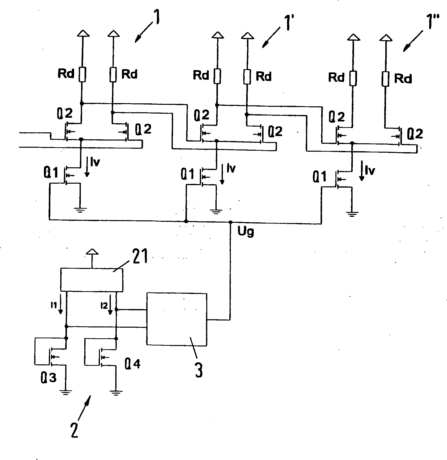
Die
Source-Anschlüsse
der beiden Transistoren Q2 einer Verstärkerstufe sind gemeinsam an den
Drain-Anschluß des
Transistors Q1 angeschlossen, der als Stromquelle dient. Der Source-Anschluß des Transistors
Q1 ist mit Masse verbunden. Die Drain-Anschlüsse der Transistoren Q2 sind
jeweils über
einen Drain-Widerstand Rd mit einer Spannungsquelle verbunden. Die
an den Drain-Anschlüssen
der Transistoren Q2 anliegenden Spannungen einer Stufe
Durch
die Gatespannung am Transistor Q1 wird jeweils der Strom durch die
einzelnen Verstärkerstufen
Dieser
Zusammenhang ist schematisch in
Die untere Kurve G3 zeigt den Strom Iv durch die Verstärkerstufe, der erfindungsgemäß durch eine entsprechende Einstel lung der Steuerspannung bzw. Gatespannung des Transistors Q1 mit abnehmender Temperatur hin reduziert wird.The lower curve G3 shows the current Iv through the amplifier stage, the invention by a corresponding SET ment of the control voltage or gate voltage of the transistor Q1 is reduced with decreasing temperature.
Da
die Steilheit eines im Sättigungsbereich betriebenen
Transistors proportional zur Wurzel des Drain-Stroms Id ist, wird
durch den reduzierten Strom Iv die Verstärkung der Verstärkerstufe
bei kleinen Temperaturen entsprechend reduziert. Dies führt dazu,
daß die
Verstärkung über den
gesamten Temperaturbereich im wesentlichen konstant ist und dem Wert
V0 entspricht. Dies ist in dem mittleren Graphen G2 der
Eine
Steuerung der Gatespannung Ug der Transistoren Q1 erfolgt mittels
eines Temperatursensors
Der
Temperatursensor
Die
Verstärkerschaltung
In
Abhängigkeit
von der Stromdichte ergibt sich eine unterschiedliche Temperaturabhängigkeit der
Gatespannung, die zur Temperaturmessung ausgenutzt wird.
Gemäß
Bei
der Schaltung gemäß
Demgegenüber wird
der Transistor Q3 an einem Arbeitspunkt oberhalb des temperaturunabhängigen Arbeitspunktes
A betrieben. In diesem Bereich ist der Temperaturkoeffizient von
Id negativ, d. h. mit zunehmender Temperatur wird eine höhere Spannung
zur Realisierung einer vorgegebenen Stromstärke I2 benötigt. So werden in
Da der Transistor Q4 im Arbeitspunkt I1 und der Transistor Q3 im Arbeitspunkt I2 betrieben werden, variiert die Spannung im Arbeitspunkt I1 in Abhängigkeit von der Temperatur, während sie im Arbeitspunkt I2 konstant bleibt. Die Differenzspannung (U2 – U1) ist proportional zur anliegenden Temperatur T, d. h. mit zunehmender Temperatur des Transistors T3 nimmt auch die Differenzspannung (U2 – U1) zu.Since the transistor Q4 operated at the operating point I1 and the transistor Q3 in the operating point I2 who , the voltage at the operating point I1 varies as a function of the temperature, while it remains constant at the operating point I2. The differential voltage (U2 - U1) is proportional to the applied temperature T, ie, as the temperature of the transistor T3 increases, the differential voltage (U2 - U1) also increases.
Die
Differenzspannung (U2 – U1)
wird von der Verstärkerschaltung
Bei
einer Abnahme der Temperatur sinkt die Spannung U1 am Transistor
Q3 des Temperatursensors
Die
Verstärkerschaltung
Durch
Variation der Ströme
I1 und I2 sowie der Transistorgrößen Q3,
Q4', Q4'' kann die Differenzspannung (U2 – U1) bei
der Schaltung gemäß
- 1, 1', 1''1, 1 ', 1' '
- Verstärkerstufeamplifier stage
- 2, 2'2, 2 '
- Temperatursensortemperature sensor
- 2121
- Stromgeneratorpower generator
- 3, 3'3, 3 '
- Verstärkerschaltungamplifier circuit
- 3131
- Operationsverstärkeroperational amplifiers
- Transistortransistor
- RdRd
- Drain-WiderstandDrain resistance
- Iviv
- Strom durch Verstärkerstufeelectricity through amplifier stage
- Idid
- Drain-Source-StromDrain-source current
- UgUg
- Steuerspannungcontrol voltage
- TT
- Temperaturtemperature
- VV
- Verstärkungreinforcement
Claims (8)
Priority Applications (1)
| Application Number | Priority Date | Filing Date | Title |
|---|---|---|---|
| DE2000138693 DE10038693C2 (en) | 2000-07-28 | 2000-07-28 | temperature sensor |
Applications Claiming Priority (1)
| Application Number | Priority Date | Filing Date | Title |
|---|---|---|---|
| DE2000138693 DE10038693C2 (en) | 2000-07-28 | 2000-07-28 | temperature sensor |
Publications (2)
| Publication Number | Publication Date |
|---|---|
| DE10066032A1 DE10066032A1 (en) | 2002-05-02 |
| DE10066032B4 true DE10066032B4 (en) | 2010-01-28 |
Family
ID=7651730
Family Applications (1)
| Application Number | Title | Priority Date | Filing Date |
|---|---|---|---|
| DE10066032A Expired - Lifetime DE10066032B4 (en) | 2000-07-28 | 2000-07-28 | Circuit arrangement for controlling the gain of an amplifier circuit |
Country Status (2)
| Country | Link |
|---|---|
| US (1) | US6667660B2 (en) |
| DE (1) | DE10066032B4 (en) |
Families Citing this family (16)
| Publication number | Priority date | Publication date | Assignee | Title |
|---|---|---|---|---|
| DE10204487B4 (en) * | 2002-01-30 | 2004-03-04 | Infineon Technologies Ag | temperature sensor |
| US7769427B2 (en) | 2002-07-16 | 2010-08-03 | Magnetics, Inc. | Apparatus and method for catheter guidance control and imaging |
| US7280863B2 (en) | 2003-10-20 | 2007-10-09 | Magnetecs, Inc. | System and method for radar-assisted catheter guidance and control |
| US6977557B1 (en) | 2004-03-25 | 2005-12-20 | Marvin Elmer Frerking | Injection mode steering oscillator |
| US7289374B2 (en) * | 2004-07-01 | 2007-10-30 | Infineon Technologies Ag | Circuit and method for adjusting threshold drift over temperature in a CMOS receiver |
| US8027714B2 (en) | 2005-05-27 | 2011-09-27 | Magnetecs, Inc. | Apparatus and method for shaped magnetic field control for catheter, guidance, control, and imaging |
| US7869854B2 (en) * | 2006-02-23 | 2011-01-11 | Magnetecs, Inc. | Apparatus for magnetically deployable catheter with MOSFET sensor and method for mapping and ablation |
| US20080249395A1 (en) * | 2007-04-06 | 2008-10-09 | Yehoshua Shachar | Method and apparatus for controlling catheter positioning and orientation |
| US20080297287A1 (en) * | 2007-05-30 | 2008-12-04 | Magnetecs, Inc. | Magnetic linear actuator for deployable catheter tools |
| US7554403B1 (en) * | 2008-02-27 | 2009-06-30 | National Semiconductor Corporation | Gainboost biasing circuit for low voltage operational amplifier design |
| US20090253985A1 (en) * | 2008-04-07 | 2009-10-08 | Magnetecs, Inc. | Apparatus and method for lorentz-active sheath display and control of surgical tools |
| US8457714B2 (en) | 2008-11-25 | 2013-06-04 | Magnetecs, Inc. | System and method for a catheter impedance seeking device |
| JP2010224594A (en) * | 2009-03-19 | 2010-10-07 | Oki Semiconductor Co Ltd | Voltage generation circuit |
| US20110112396A1 (en) | 2009-11-09 | 2011-05-12 | Magnetecs, Inc. | System and method for targeting catheter electrodes |
| EP2611028A1 (en) * | 2011-12-30 | 2013-07-03 | Dialog Semiconductor GmbH | Multi-stage fully differential amplifier with controlled common mode voltage |
| CN107202649B (en) * | 2017-05-02 | 2019-07-26 | 邱翠雯 | A kind of temperature sensor of high-precision wide output voltage |
Citations (3)
| Publication number | Priority date | Publication date | Assignee | Title |
|---|---|---|---|---|
| US4636742A (en) * | 1983-10-27 | 1987-01-13 | Fujitsu Limited | Constant-current source circuit and differential amplifier using the same |
| US5336943A (en) * | 1991-07-19 | 1994-08-09 | U.S. Philips Corporation | Temperature sensing circuit |
| US5818294A (en) * | 1996-07-18 | 1998-10-06 | Advanced Micro Devices, Inc. | Temperature insensitive current source |
Family Cites Families (15)
| Publication number | Priority date | Publication date | Assignee | Title |
|---|---|---|---|---|
| US3566296A (en) * | 1967-11-15 | 1971-02-23 | Ibm | Transistor differential amplifier |
| CH532778A (en) | 1971-06-21 | 1973-01-15 | Centre Electron Horloger | Temperature sensor device |
| US4413235A (en) * | 1981-02-23 | 1983-11-01 | Motorola, Inc. | Low temperature coefficient logarithmic electronic gain controlled amplifier |
| DE3329665A1 (en) * | 1983-08-17 | 1985-03-07 | Telefunken electronic GmbH, 7100 Heilbronn | CIRCUIT ARRANGEMENT FOR THE AMPLIFICATION OF ELECTRICAL SIGNALS |
| DE3671581D1 (en) | 1985-07-09 | 1990-06-28 | Siemens Ag | MOSFET WITH TEMPERATURE PROTECTION. |
| JP2808909B2 (en) | 1990-04-27 | 1998-10-08 | 日本電気株式会社 | Power semiconductor device |
| US5355123A (en) | 1990-07-17 | 1994-10-11 | Fuji Electric Co., Ltd. | Overheating detection circuit for detecting overheating of a power device |
| JP3132587B2 (en) | 1990-11-26 | 2001-02-05 | 富士電機株式会社 | Power device overheat detection circuit |
| US5099156A (en) | 1990-10-02 | 1992-03-24 | California Institute Of Technology | Subthreshold MOS circuits for correlating analog input voltages |
| CA2066929C (en) | 1991-08-09 | 1996-10-01 | Katsuji Kimura | Temperature sensor circuit and constant-current circuit |
| JPH07225622A (en) * | 1994-02-10 | 1995-08-22 | Fujitsu Ltd | Constant current circuit using field effect transistor |
| JP3485655B2 (en) | 1994-12-14 | 2004-01-13 | 株式会社ルネサステクノロジ | Composite MOSFET |
| JPH09119870A (en) | 1995-10-26 | 1997-05-06 | Nec Corp | Temperature detecting method, semiconductor device, and temperature detecting circuit |
| KR100298435B1 (en) * | 1998-06-03 | 2001-08-07 | 김영환 | Auto gain controller having a temperature compensation function |
| US6278325B1 (en) * | 2000-12-13 | 2001-08-21 | Industrial Technology Research Institute | Programmable gain amplifier with a large extent for the variation of gains |
-
2000
- 2000-07-28 DE DE10066032A patent/DE10066032B4/en not_active Expired - Lifetime
-
2001
- 2001-07-30 US US09/918,190 patent/US6667660B2/en not_active Expired - Lifetime
Patent Citations (3)
| Publication number | Priority date | Publication date | Assignee | Title |
|---|---|---|---|---|
| US4636742A (en) * | 1983-10-27 | 1987-01-13 | Fujitsu Limited | Constant-current source circuit and differential amplifier using the same |
| US5336943A (en) * | 1991-07-19 | 1994-08-09 | U.S. Philips Corporation | Temperature sensing circuit |
| US5818294A (en) * | 1996-07-18 | 1998-10-06 | Advanced Micro Devices, Inc. | Temperature insensitive current source |
Also Published As
| Publication number | Publication date |
|---|---|
| DE10066032A1 (en) | 2002-05-02 |
| US6667660B2 (en) | 2003-12-23 |
| US20020014918A1 (en) | 2002-02-07 |
Similar Documents
| Publication | Publication Date | Title |
|---|---|---|
| DE10204487B4 (en) | temperature sensor | |
| DE10066032B4 (en) | Circuit arrangement for controlling the gain of an amplifier circuit | |
| DE69011756T2 (en) | Current mirror circuit. | |
| DE69606612T2 (en) | Reference voltage circuit | |
| DE19841202C1 (en) | Temperature sensor for load cut-out device, to provide temperature over loading protection | |
| DE19530472B4 (en) | Constant current circuit | |
| DE2522437A1 (en) | TEMPERATURE MEASURING CONVERTER | |
| DE102009054113A1 (en) | Process, voltage and temperature control for high-speed, high-gain amplifiers with variable gain and low power consumption based on Mosfet resistors | |
| EP0525235A1 (en) | Hall sensor with self-compensation | |
| DE2541578A1 (en) | TEMPERATURE SENSOR | |
| DE68928959T2 (en) | Logic circuitry | |
| DE2947771C2 (en) | Directly coupled amplifier arrangement with stabilization of the output direct current | |
| DE2855303A1 (en) | LINEAR AMPLIFIER | |
| DE102017125831A1 (en) | Temperature compensated reference voltage circuit | |
| DE69130124T2 (en) | Logarithmic amplifier | |
| EP1336136B1 (en) | Method for adjusting a bgr circuit | |
| DE10032527C1 (en) | Temperature compensation circuit for Hall element has two band separation reference circuits with resistances of two types, comparator comparing Hall voltage with reference potential | |
| DE10224747B4 (en) | Sensor circuit and method for manufacturing the same | |
| DE69815289T2 (en) | VOLTAGE REGULATOR CIRCUITS AND SEMICONDUCTOR CIRCUIT | |
| DE2445738C2 (en) | Power amplifier with temperature compensation | |
| DE3853425T2 (en) | VOLTAGE CONTROL DEVICE. | |
| DE102019124959A1 (en) | HEAT SENSOR WITH LOW TEMPERATURE ERROR | |
| EP0498799A1 (en) | Integratable temperature sensor circuit | |
| DE19855870B4 (en) | Flow sensor of the heat sensitive type | |
| DE10047620B4 (en) | Circuit for generating a reference voltage on a semiconductor chip |
Legal Events
| Date | Code | Title | Description |
|---|---|---|---|
| AC | Divided out of |
Ref document number: 10038693 Country of ref document: DE |
|
| AC | Divided out of |
Ref document number: 10038693 Country of ref document: DE |
|
| OP8 | Request for examination as to paragraph 44 patent law | ||
| AC | Divided out of |
Ref document number: 10038693 Country of ref document: DE |
|
| AC | Divided out of |
Ref document number: 10038693 Country of ref document: DE Kind code of ref document: P |
|
| 8364 | No opposition during term of opposition | ||
| 8327 | Change in the person/name/address of the patent owner |
Owner name: LANTIQ DEUTSCHLAND GMBH, 85579 NEUBIBERG, DE |
|
| R081 | Change of applicant/patentee |
Owner name: LANTIQ DEUTSCHLAND GMBH, DE Free format text: FORMER OWNER: INFINEON TECHNOLOGIES AG, 81669 MUENCHEN, DE Effective date: 20110325 Owner name: LANTIQ BETEILIGUNGS-GMBH & CO. KG, DE Free format text: FORMER OWNER: INFINEON TECHNOLOGIES AG, 81669 MUENCHEN, DE Effective date: 20110325 |
|
| R081 | Change of applicant/patentee |
Owner name: INTEL CORP., SANTA CLARA, US Free format text: FORMER OWNER: LANTIQ DEUTSCHLAND GMBH, 85579 NEUBIBERG, DE Owner name: LANTIQ BETEILIGUNGS-GMBH & CO. KG, DE Free format text: FORMER OWNER: LANTIQ DEUTSCHLAND GMBH, 85579 NEUBIBERG, DE |
|
| R071 | Expiry of right | ||
| R081 | Change of applicant/patentee |
Owner name: INTEL CORP., SANTA CLARA, US Free format text: FORMER OWNER: LANTIQ BETEILIGUNGS-GMBH & CO. KG, 85579 NEUBIBERG, DE |