CN2789971Y - Matrix Board-to-Board Connector Combination - Google Patents
Matrix Board-to-Board Connector Combination Download PDFInfo
- Publication number
- CN2789971Y CN2789971Y CNU200520057149XU CN200520057149U CN2789971Y CN 2789971 Y CN2789971 Y CN 2789971Y CN U200520057149X U CNU200520057149X U CN U200520057149XU CN 200520057149 U CN200520057149 U CN 200520057149U CN 2789971 Y CN2789971 Y CN 2789971Y
- Authority
- CN
- China
- Prior art keywords
- connector
- board
- substrate
- base portion
- fastening piece
- Prior art date
- Legal status (The legal status is an assumption and is not a legal conclusion. Google has not performed a legal analysis and makes no representation as to the accuracy of the status listed.)
- Expired - Fee Related
Links
- 239000011159 matrix material Substances 0.000 title claims abstract description 34
- 239000000758 substrate Substances 0.000 claims description 32
- 238000003466 welding Methods 0.000 claims description 12
- 230000007704 transition Effects 0.000 claims description 3
- 238000007373 indentation Methods 0.000 claims 1
- 238000005452 bending Methods 0.000 abstract description 3
- 238000011084 recovery Methods 0.000 abstract description 2
- 230000000903 blocking effect Effects 0.000 description 4
- 238000003780 insertion Methods 0.000 description 3
- 230000037431 insertion Effects 0.000 description 3
- 238000000034 method Methods 0.000 description 3
- 238000005476 soldering Methods 0.000 description 3
- 230000007547 defect Effects 0.000 description 2
- 239000007769 metal material Substances 0.000 description 2
- 230000000149 penetrating effect Effects 0.000 description 2
- 230000008054 signal transmission Effects 0.000 description 2
- 230000004888 barrier function Effects 0.000 description 1
- 238000010586 diagram Methods 0.000 description 1
- 230000013011 mating Effects 0.000 description 1
- 229910000679 solder Inorganic materials 0.000 description 1
Images


Landscapes
- Coupling Device And Connection With Printed Circuit (AREA)
Abstract
本实用新型公开了一种矩阵式板对板连接器组合,包括第一连接器及第二连接器。第一连接器上固定有第一扣合片,第一扣合片具有扣合部,扣合部由第一扣合片的下侧向外弯折延伸而成。第二连接器上固定有第二扣合片,第二扣合片具有弹性部,弹性部以一定形状弯折,使第一、二连接器在完全插接时弹性部因弹性回复而撞击第一扣合片的扣合部,从而发出撞击声,以供使用者判断第一、二连接器是否完全插接在一起。
The utility model discloses a matrix type board-to-board connector assembly, comprising a first connector and a second connector. A first buckle piece is fixed on the first connector, and the first buckle piece has a buckle part, which is formed by bending outward and extending from the lower side of the first buckle piece. A second buckle piece is fixed on the second connector, and the second buckle piece has an elastic part, which is bent in a certain shape, so that when the first and second connectors are fully plugged in, the elastic part hits the buckle part of the first buckle piece due to elastic recovery, thereby emitting a knocking sound, so that the user can judge whether the first and second connectors are fully plugged in together.
Description
所属技术领域Technical field
本实用新型涉及一种板对板连接器组合,尤其涉及一种矩阵式板对板连接器组合。The utility model relates to a board-to-board connector combination, in particular to a matrix type board-to-board connector combination.
背景技术Background technique
请参阅图10,其揭示了一种现有矩阵式板对板连接器组合20,包括相互扣合的第一连接器300以及第二连接器400,两连接器300、400分别固定于不同的电路板上(图中未示),以将两电路板电性连接,从而达成两电路板间的信号传输。Please refer to FIG. 10 , which discloses an existing matrix board-to-
请参阅图11,该现有矩阵式板对板连接器组合20的第一连接器300包括第一壳体310以及固定在第一壳体310上的多个第一端子320。第一壳体310具有第一基板311。第一基板311的前后两侧的边角处均开设有凹口313。第一基板311的左右两侧均向上垂直延伸出一侧壁314,侧壁314的两端均分别沿第一基板311的前后两侧垂直延伸出阻挡臂315。阻挡臂315及两侧壁314围成一容纳空间,用以容纳第二连接器400。沿阻挡臂315的延伸方向,第一卡块316从阻挡臂315上突出,用以卡固第二连接器400。Referring to FIG. 11 , the
请参阅图12,该现有矩阵式板对板连接器组合20的第二连接器400包括第二壳体410以及固定在第二壳体410上的多个第二端子420。第二壳体410的四角处均竖直向上延伸出一固定脚412以及横向延伸出一第二卡块416。在第二连接器400与第一连接器300插接时,固定脚412向下伸入第一连接器300的凹口313中,并使第二卡块416与第一连接器300的第一卡块316相互卡扣配合,从而将第二连接器400卡固在第一连接器300上。Referring to FIG. 12 , the
然而,由于该现有矩阵式板对板连接器组合20通过第一卡块316与第二卡块416相互卡扣配合而将两连接器300、400扣合在一起,第一卡块316与第二卡块416仅起扣合作用,在将两连接器300、400进行插接时,使用者并不能确定第一连接器300与第二连接器400是否完全插接在一起。However, because the existing matrix board-to-
实用新型内容Utility model content
本实用新型的目的是针对上述现有技术存在的缺陷提供一种矩阵式板对板连接器组合,在该矩阵式板对板连接器组合的第一连接器与第二连接器插接过程中,使用者能确定两连接器是否完全插接在一起。The purpose of this utility model is to provide a matrix type board-to-board connector combination for the above-mentioned defects in the prior art. During the insertion process of the first connector and the second connector of the matrix type board-to-board connector combination , the user can determine whether the two connectors are fully mated together.
为实现上述目的,本实用新型提供一种矩阵式板对板连接器组合,包括第一连接器及第二连接器。第一连接器包括第一壳体、多个第一端子以及第一扣合片。第一壳体具有第一基板及侧板,侧板由第一基板垂直向上延伸而成,并且第一基板于邻近侧板处开设有缺口。多个第一端子固定于第一基板上。第一扣合片具有第一基部、卡合部、第一焊接脚及扣合部。卡合部固定于第一连接器的侧板上,其由第一基部平行延伸而成。第一焊接脚由第一基部的下侧向下垂直延伸而成,以将第一扣合片焊接到外部一电路板上。扣合部由第一基部的下侧向外弯折延伸而成。第二连接器包括第二壳体、第二端子及第二扣合片。第二壳体具有第二基板及导接壁,导接壁由第二基板垂直向下延伸而成,且该导接壁上开设有贯穿第二基板顶面的收容槽。多个第二端子固定于第二基板上。第二扣合片具有第二基部、弹性部及第二焊接脚;第二基部固定于第二连接器的第二基板上;弹性部收容于第二基板的收容槽中,该弹性部具有固定端、转接臂及自由端,固定端由第二基部下侧向下垂直延伸而成,转接臂由固定端向外弯折延伸而成,自由端由转接臂向上延伸而成,并且自由端与转接臂的连接处自下而上先向外凸后向内凹而呈凸弧与凹弧过渡状,以使自由端弹性抵压第一连接器的第一扣合片的扣合部;第二焊接脚由第二基部的上侧向上垂直延伸而成,以将第二扣合片焊接到外部另一电路板上。In order to achieve the above purpose, the utility model provides a matrix type board-to-board connector assembly, including a first connector and a second connector. The first connector includes a first shell, a plurality of first terminals and a first snap-fit piece. The first casing has a first base plate and a side plate. The side plate is formed by vertically extending upward from the first base plate, and a gap is opened on the first base plate adjacent to the side plate. A plurality of first terminals are fixed on the first substrate. The first fastening piece has a first base, a fastening part, a first welding foot and a fastening part. The engaging part is fixed on the side plate of the first connector, and is formed by parallel extension of the first base part. The first soldering foot is vertically extended downwards from the lower side of the first base to solder the first fastening sheet to an external circuit board. The fastening part is formed by bending and extending outward from the lower side of the first base part. The second connector includes a second shell, a second terminal and a second buckling piece. The second housing has a second base plate and a guide wall, the guide wall extends vertically downward from the second base plate, and the guide wall is provided with a receiving groove penetrating through the top surface of the second base plate. A plurality of second terminals are fixed on the second substrate. The second fastening piece has a second base, an elastic portion, and a second welding foot; the second base is fixed on the second substrate of the second connector; the elastic portion is accommodated in the receiving groove of the second substrate, and the elastic portion has a fixed end, an adapter arm and a free end, the fixed end is formed by extending vertically downward from the lower side of the second base, the adapter arm is formed by bending and extending outward from the fixed end, and the free end is formed by extending upward from the adapter arm, and The connection between the free end and the adapter arm is first convex outward and then concave inward from bottom to top, forming a transition shape between a convex arc and a concave arc, so that the free end elastically presses against the buckle of the first fastening piece of the first connector The joint part; the second welding foot is vertically extended upward from the upper side of the second base, so as to weld the second buckle piece to another external circuit board.
由上所述,在本实用新型矩阵式板对板连接器组合的第一及第二连接器的插接过程中,固定于第二连接器上的第二扣合片的弹性部弹性抵压固定于第一连接器上的第一扣合片的第一基部,并在两连接器完全插接在一起时,弹性部弹性回复而使弹性部的自由端撞击第一扣合片的扣合部,从而发出撞击声,以提示两连接器已完全插接在一起。故而,使用者能确定本实用新型矩阵式板对板连接器组合的两连接器是否完全插接在一起。From the above, during the insertion process of the first and second connectors of the matrix board-to-board connector combination of the present invention, the elastic part of the second snap-fit piece fixed on the second connector elastically presses It is fixed on the first base of the first fastening piece on the first connector, and when the two connectors are fully plugged together, the elastic part elastically recovers so that the free end of the elastic part hits the fastening of the first fastening piece to make a clicking sound to indicate that the two connectors are fully mated together. Therefore, the user can determine whether the two connectors of the matrix board-to-board connector assembly of the present invention are fully plugged together.
附图说明Description of drawings
下面结合附图和实施例对本实用新型作进一步详细的描述。Below in conjunction with accompanying drawing and embodiment the utility model is described in further detail.
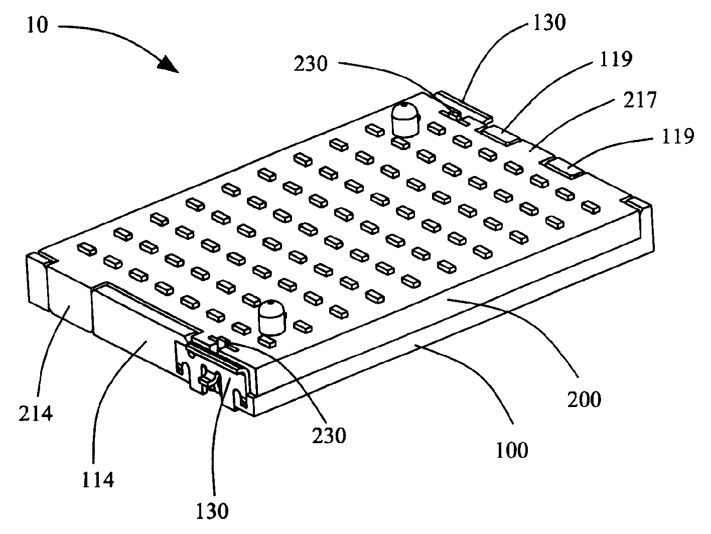
图1是本实用新型矩阵式板对板连接器组合的立体组合图。Fig. 1 is a three-dimensional assembly diagram of the matrix board-to-board connector assembly of the present invention.
图2是图1所示矩阵式板对板连接器组合的第一连接器的立体组合图。FIG. 2 is a perspective assembly view of the first connector of the matrix board-to-board connector assembly shown in FIG. 1 .
图3是图2所示第一连接器的立体分解图。FIG. 3 is an exploded perspective view of the first connector shown in FIG. 2 .
图4是图3所示第一连接器的第一扣合片的立体图。FIG. 4 is a perspective view of a first fastening piece of the first connector shown in FIG. 3 .
图5是图1所示矩阵式板对板连接器组合的第二连接器的立体组合图。FIG. 5 is a perspective assembly view of the second connector of the matrix board-to-board connector assembly shown in FIG. 1 .
图6是图5所示第二连接器的立体分解图。FIG. 6 is an exploded perspective view of the second connector shown in FIG. 5 .
图7是图6所示第二连接器的第二扣合片的立体图。FIG. 7 is a perspective view of a second fastening piece of the second connector shown in FIG. 6 .
图8是图1所示矩阵式板对板连接器组合的俯视图。FIG. 8 is a top view of the matrix board-to-board connector assembly shown in FIG. 1 .
图9是图8所示的IX-IX剖视图。Fig. 9 is a sectional view taken along line IX-IX shown in Fig. 8 .
图10是现有矩阵式板对板连接器组合的立体组合图。Fig. 10 is a three-dimensional assembled view of the existing matrix board-to-board connector assembly.
图11是现有矩阵式板对板连接器组合的第一连接器的立体组合图。Fig. 11 is a three-dimensional assembled view of the first connector of the conventional matrix board-to-board connector assembly.
图12是现有矩阵式板对板连接器组合的第二连接器的立体组合图。Fig. 12 is a three-dimensional assembled view of the second connector of the conventional matrix board-to-board connector assembly.
图中,10、20.矩阵式板对板连接器组合,100、300.第一连接器,110、310.第一壳体,111、311.第一基板,112.第一端子孔,113A.第一缺口,113B.第二缺口,114.第一侧板,115.卡合槽,116.第一固定孔,117.凸部,118.第二固定孔,119.第二侧板,119A.防呆槽,120、320.第一端子,130.第一扣合片,131.第一基部,132.卡合部,133.第一固定脚,134.第一焊接脚,135.第二固定脚,136.扣合部,137.折边,200、400.第二连接器,210、410.第二壳体,211.第二基板,212.第二端子孔,213.第一导接壁,214.第二导接壁,215.固定槽,216.收容槽,217.防呆块,220、420.第二端子,230.第二扣合片,231.第二基部,232.固持臂,233.弹性部,234.固定端,235.转接臂,236.自由端,237.第二焊接脚,313.凹口,314.侧壁,315.阻挡臂,316.第一卡块,412.固定脚,416.第二卡块。In the figure, 10, 20. matrix board-to-board connector combination, 100, 300. first connector, 110, 310. first housing, 111, 311. first substrate, 112. first terminal hole, 113A The first notch, 113B. The second notch, 114. The first side plate, 115. The engaging groove, 116. The first fixing hole, 117. The protrusion, 118. The second fixing hole, 119. The second side plate, 119A. Anti-fooling slot, 120, 320. First terminal, 130. First fastening piece, 131. First base, 132. Snapping part, 133. First fixing foot, 134. First welding foot, 135. Second fixing foot, 136. Fastening part, 137. Flange, 200, 400. Second connector, 210, 410. Second housing, 211. Second base plate, 212. Second terminal hole, 213. No. One guide wall, 214. second guide wall, 215. fixing groove, 216. receiving groove, 217. fool-proof block, 220, 420. second terminal, 230. second fastening piece, 231. second base , 232. Holding arm, 233. Elastic part, 234. Fixed end, 235. Adapter arm, 236. Free end, 237. Second welding foot, 313. Notch, 314. Side wall, 315. Blocking arm, 316 . The first block, 412. The fixed foot, 416. The second block.
具体实施方式Detailed ways
请参阅图1,本实用新型矩阵式板对板连接器组合10包括第一连接器100及第二连接器200。第一连接器100与第二连接器200分别焊接至两个不同的电路板上(图中未示),并通过两连接器100、200的插接配合而达成两电路板间的电性连接及讯号传输。Please refer to FIG. 1 , the matrix board-to-
请参阅图2及图3,第一连接器100包括第一壳体110、多个第一端子120以及两第一扣合片130。第一壳体110具有第一基板111,第一基板111上开设有与第一端子120等数量并呈矩阵状排列的第一端子孔112,用于固定第一端子120。第一基板111前后两端均形成第一缺口113A及第二缺口113B(后端两缺口图中未示)。在前端两缺口113A、113B之间,第一基板111前端中部向上垂直延伸出一第一侧板114。在邻近第一缺口113A处,第一侧板114上开设有卡合槽115,并且于卡合槽115的下方,第一侧板114上还开设有一朝向第一基板111的第一固定孔116。第一基板111前端右侧于邻近第一缺口113A处形成一凸部117,凸部117上开设有与第一固定孔116平行的第二固定孔118。在后端两缺口113A、113B之间,第一基板111向上垂直延伸出两第二侧板119,两第二侧板119之间形成一防呆槽119A。Please refer to FIG. 2 and FIG. 3 , the
请参阅图4,第一扣合片130由金属材料制成,该第一扣合片130具有第一基部131。第一基部131的左侧平行延伸出一卡合部132,卡合部132的下侧向后垂直延伸出第一固定脚133。第一基部131下侧左右两端分别向下垂直延伸出两第一焊接脚134;第一基部131下侧右端还向后垂直延伸出一第二固定脚135;第一基部131下侧中部向前弯折延伸出一扣合部136。第一基部131上侧则进一步向前弯折形成一折边137。Please refer to FIG. 4 , the
请再参阅图2,在将第一扣合片130固定于第一壳体110上时,卡合部132卡入第一侧板114的卡合槽115内,第一固定脚133及第二固定脚135分别插入第一固定孔116及第二固定孔118内,从而将第一扣合片130固定于第一壳体110上。两第一焊接脚134穿过第一缺口113A并伸出第一基板111的底面,从而可将第一扣合片130焊接至相应电路板上。Please refer to Fig. 2 again, when the
请参阅图5及图6,第二连接器200包括第二壳体210、多个第二端子220及两第二扣合片230。第二壳体210具有一第二基板211,第二基板211上开设有与第二端子220等数量并呈矩阵状排列的第二端子孔212,用以固定第二端子220。第二基板211的前后两端均向下垂直延伸出一第一导接壁213及第二导接壁214(两后端导接壁图中未示)。于邻近前端第一导接壁213处,第二基板211上横向开设有一固定槽215。第一导接壁213上开设有贯穿第二基板211的顶面并与固定槽215连通的收容槽216。此外,第二基板211后端的中部还向后延伸出一防呆块217。Please refer to FIG. 5 and FIG. 6 , the
请参阅图7,第二扣合片230也由金属材料制成,以提高其与第二扣合片230扣合时(容后详述)的耐磨性,从而可以避免现有矩阵式板对板连接器组合因多次扣合磨损而使其扣合不牢。该第二扣合片230具有第二基部231。第二基部231下侧两端分别向下垂直延伸出两固持臂232。第二基部231下侧中部延伸出一大致呈“U”形的弹性部233。弹性部233具有一固定端234、一转接臂235及一自由端236;固定端234由第二基部231下侧中部向下垂直延伸而成;转接臂235由固定端234向外弯折延伸而成;自由端236由转接臂235向上延伸而成,并且自由端236与转接臂235的连接处自下而上先向外凸后向内凹而呈凸弧与凹弧过渡状。第二基部231上侧中部向上垂直延伸出一第二焊接脚237。Please refer to Fig. 7, the
请再参阅图5,在将第二扣合片230固定于第二壳体210上时,第二基部231及两固持臂232固定于第二基板211的固定槽215内,并且第二焊接脚237伸出第二基板211的顶面,以将第二扣合片230焊接另一电路板上;弹性部233收容于收容槽216内,并且弹性部233的自由端236与转接臂235的连接处突出第一导接壁213的外侧面。Please refer to Fig. 5 again, when the
请参阅图1、图8及图9,当第二连接器200与第一连接器100插接时,第二连接器200的第一导接壁213向下插入第一连接器100的第一缺口113A中,第二导接壁214插入第二缺口113B中,以导引两连接器100、200插接。防呆块217插入防呆槽119A中,以防止两连接器100、200插反。第二扣合片230的弹性部233的自由端236与转接臂235的连接处抵压第一扣合片130的第一基部131而使弹性部233发生弹性形变;当第二连接器200完全插接于第一连接器100上时,弹性部233由于弹性回复而使自由端236撞击扣合部136,从而发出撞击声,以提示第二连接器200与第一连接器100已完全插接在一起。此外,第一基部131的折边137也可导引第二连接器200插接于第一连接器100上,以防止两连接器100、200未能精确对准时,第一基部131的上侧沿抵顶第二连接器200而阻挡两连接器100、200的插接。Referring to FIG. 1 , FIG. 8 and FIG. 9 , when the
由上所述,本实用新型矩阵式板对板连接器组合通过固定于第一连接器100上的第一扣合片130以及固定于第二连接器200上的第二扣合片230,在两连接器100、200插接时,第二扣合片230的弹性部233弹性抵压第一扣合片130的第一基部131,并在两连接器100、200完全插接在一起时,弹性部233弹性回复而使自由端236撞击扣合部136,从而发出撞击声,以提示此时第二连接器200与第一连接器100已完全插接在一起。故而,本实用新型矩阵式板对板连接器组合能克服现有矩阵式板对板连接器组合的缺陷。As mentioned above, the matrix board-to-board connector assembly of the present invention is fixed on the
Claims (5)
Priority Applications (1)
| Application Number | Priority Date | Filing Date | Title |
|---|---|---|---|
| CNU200520057149XU CN2789971Y (en) | 2005-04-13 | 2005-04-13 | Matrix Board-to-Board Connector Combination |
Applications Claiming Priority (1)
| Application Number | Priority Date | Filing Date | Title |
|---|---|---|---|
| CNU200520057149XU CN2789971Y (en) | 2005-04-13 | 2005-04-13 | Matrix Board-to-Board Connector Combination |
Publications (1)
| Publication Number | Publication Date |
|---|---|
| CN2789971Y true CN2789971Y (en) | 2006-06-21 |
Family
ID=36790303
Family Applications (1)
| Application Number | Title | Priority Date | Filing Date |
|---|---|---|---|
| CNU200520057149XU Expired - Fee Related CN2789971Y (en) | 2005-04-13 | 2005-04-13 | Matrix Board-to-Board Connector Combination |
Country Status (1)
| Country | Link |
|---|---|
| CN (1) | CN2789971Y (en) |
Cited By (1)
| Publication number | Priority date | Publication date | Assignee | Title |
|---|---|---|---|---|
| CN111009760A (en) * | 2018-11-21 | 2020-04-14 | 富鼎精密工业(郑州)有限公司 | Electrical connector |
-
2005
- 2005-04-13 CN CNU200520057149XU patent/CN2789971Y/en not_active Expired - Fee Related
Cited By (1)
| Publication number | Priority date | Publication date | Assignee | Title |
|---|---|---|---|---|
| CN111009760A (en) * | 2018-11-21 | 2020-04-14 | 富鼎精密工业(郑州)有限公司 | Electrical connector |
Similar Documents
| Publication | Publication Date | Title |
|---|---|---|
| CN2800581Y (en) | Stack-type electric connector | |
| JP4851510B2 (en) | Electrical connector | |
| CN2850045Y (en) | Electric connector assembly | |
| CN1272703A (en) | Electric connector | |
| CN2638272Y (en) | Electric connector | |
| TW201112542A (en) | Connector | |
| CN2567804Y (en) | Electric connector subassembly | |
| CN201072832Y (en) | Board-to-board connector | |
| US8162680B2 (en) | Board-mounted electrical connector | |
| JP4820558B2 (en) | connector | |
| TWM270515U (en) | Matrix board-to-board connector assembly | |
| CN2789971Y (en) | Matrix Board-to-Board Connector Combination | |
| US9413111B2 (en) | Electrical connector assembly having foolproof structure | |
| US8123541B2 (en) | Electrical connector with expanded cover | |
| CN2618324Y (en) | Low Profile Board-to-Board Connector Combo | |
| CN200956438Y (en) | Electrical connector structure | |
| CN2744021Y (en) | Shielding shell and connector with the shielding shell | |
| CN2697864Y (en) | Flexible PCB Connectors | |
| CN2731926Y (en) | Shielding shell and connector with the shielding shell | |
| CN2687877Y (en) | Board-to-board electric connector | |
| CN2891366Y (en) | micro socket connector | |
| CN2610511Y (en) | electrical connector | |
| TWM628597U (en) | Connector assembly | |
| CN201270321Y (en) | electrical connector | |
| CN202395197U (en) | Universal Serial Bus connector |
Legal Events
| Date | Code | Title | Description |
|---|---|---|---|
| C14 | Grant of patent or utility model | ||
| GR01 | Patent grant | ||
| C17 | Cessation of patent right | ||
| CF01 | Termination of patent right due to non-payment of annual fee |
Granted publication date: 20060621 Termination date: 20120413 |