[go: up one dir, main page]

CN2617303Y - Tableware cleaner - Google Patents

Tableware cleaner Download PDF

Info

Publication number
CN2617303Y
CN2617303Y CNU032512821U CN03251282U CN2617303Y CN 2617303 Y CN2617303 Y CN 2617303Y CN U032512821 U CNU032512821 U CN U032512821U CN 03251282 U CN03251282 U CN 03251282U CN 2617303 Y CN2617303 Y CN 2617303Y
Authority
CN
China
Prior art keywords
valve body
washing
washing water
outlet
cleaning
Prior art date
Legal status (The legal status is an assumption and is not a legal conclusion. Google has not performed a legal analysis and makes no representation as to the accuracy of the status listed.)
Expired - Fee Related
Application number
CNU032512821U
Other languages
Chinese (zh)
Inventor
大山真
乾浩章
Current Assignee (The listed assignees may be inaccurate. Google has not performed a legal analysis and makes no representation or warranty as to the accuracy of the list.)
Panasonic Holdings Corp
Original Assignee
Matsushita Electric Industrial Co Ltd
Priority date (The priority date is an assumption and is not a legal conclusion. Google has not performed a legal analysis and makes no representation as to the accuracy of the date listed.)
Filing date
Publication date
Priority claimed from JP2002148714A external-priority patent/JP3835347B2/en
Priority claimed from JP2002148713A external-priority patent/JP3829759B2/en
Priority claimed from JP2002148715A external-priority patent/JP3835348B2/en
Application filed by Matsushita Electric Industrial Co Ltd filed Critical Matsushita Electric Industrial Co Ltd
Application granted granted Critical
Publication of CN2617303Y publication Critical patent/CN2617303Y/en
Anticipated expiration legal-status Critical
Expired - Fee Related legal-status Critical Current

Links

Images

Classifications

    • BPERFORMING OPERATIONS; TRANSPORTING
    • B28WORKING CEMENT, CLAY, OR STONE
    • B28CPREPARING CLAY; PRODUCING MIXTURES CONTAINING CLAY OR CEMENTITIOUS MATERIAL, e.g. PLASTER
    • B28C7/00Controlling the operation of apparatus for producing mixtures of clay or cement with other substances; Supplying or proportioning the ingredients for mixing clay or cement with other substances; Discharging the mixture
    • B28C7/0007Pretreatment of the ingredients, e.g. by heating, sorting, grading, drying, disintegrating; Preventing generation of dust
    • B28C7/0023Pretreatment of the ingredients, e.g. by heating, sorting, grading, drying, disintegrating; Preventing generation of dust by heating or cooling
    • B28C7/003Heating, e.g. using steam
    • BPERFORMING OPERATIONS; TRANSPORTING
    • B28WORKING CEMENT, CLAY, OR STONE
    • B28BSHAPING CLAY OR OTHER CERAMIC COMPOSITIONS; SHAPING SLAG; SHAPING MIXTURES CONTAINING CEMENTITIOUS MATERIAL, e.g. PLASTER
    • B28B13/00Feeding the unshaped material to moulds or apparatus for producing shaped articles; Discharging shaped articles from such moulds or apparatus
    • B28B13/02Feeding the unshaped material to moulds or apparatus for producing shaped articles
    • BPERFORMING OPERATIONS; TRANSPORTING
    • B28WORKING CEMENT, CLAY, OR STONE
    • B28CPREPARING CLAY; PRODUCING MIXTURES CONTAINING CLAY OR CEMENTITIOUS MATERIAL, e.g. PLASTER
    • B28C7/00Controlling the operation of apparatus for producing mixtures of clay or cement with other substances; Supplying or proportioning the ingredients for mixing clay or cement with other substances; Discharging the mixture
    • B28C7/04Supplying or proportioning the ingredients
    • B28C7/0481Plant for proportioning, supplying or batching
    • CCHEMISTRY; METALLURGY
    • C04CEMENTS; CONCRETE; ARTIFICIAL STONE; CERAMICS; REFRACTORIES
    • C04BLIME, MAGNESIA; SLAG; CEMENTS; COMPOSITIONS THEREOF, e.g. MORTARS, CONCRETE OR LIKE BUILDING MATERIALS; ARTIFICIAL STONE; CERAMICS; REFRACTORIES; TREATMENT OF NATURAL STONE
    • C04B16/00Use of organic materials as fillers, e.g. pigments, for mortars, concrete or artificial stone; Treatment of organic materials specially adapted to enhance their filling properties in mortars, concrete or artificial stone
    • C04B16/04Macromolecular compounds

Landscapes

  • Chemical & Material Sciences (AREA)
  • Engineering & Computer Science (AREA)
  • Ceramic Engineering (AREA)
  • Dispersion Chemistry (AREA)
  • Materials Engineering (AREA)
  • Structural Engineering (AREA)
  • Organic Chemistry (AREA)
  • Manufacturing & Machinery (AREA)
  • Mechanical Engineering (AREA)
  • Washing And Drying Of Tableware (AREA)
  • Cleaning By Liquid Or Steam (AREA)
  • Lift Valve (AREA)

Abstract

本实用新型的餐具清洗机即使在有剩菜等异物流入分水装置的场合下,也能够可靠地进行清洗通路的切换。本实用新型的餐具清洗机中设有对被供给洗涤水的清洗装置27进行切换的分水装置37,分水装置37中设有阀壳40和在阀壳40中可以自由转动的阀体41。阀壳40上具有分别与清洗装置27连通的多个流出口39。随着所述阀体41的转动,有洗涤水供给的流出口39也发生切换,同时,所述阀体41被设置成可以移动,能够从设有所述流出口39的表面上移离。

Figure 03251282

The tableware cleaning machine of the utility model can reliably switch the cleaning channels even when foreign food such as leftovers flows into the water separating device. The tableware cleaning machine of the present utility model is provided with a water diversion device 37 for switching the cleaning device 27 supplied with washing water, and the water diversion device 37 is provided with a valve housing 40 and a valve body 41 which can rotate freely in the valve housing 40 . The valve casing 40 has a plurality of outlets 39 respectively communicating with the cleaning device 27 . Along with the rotation of the valve body 41 , the outlet 39 supplied with washing water is also switched. At the same time, the valve body 41 is configured to be movable and can be removed from the surface on which the outlet 39 is provided.

Figure 03251282

Description

餐具清洗机dish washer

技术领域technical field

本实用新型涉及一种通过向餐具喷射洗涤水将其清洗的餐具清洗机。The utility model relates to a tableware cleaning machine for cleaning tableware by spraying washing water.

背景技术Background technique

现有的一般餐具清洗机的结构如图40中所示。下面对其构成进行说明。The structure of an existing general dishwasher is shown in FIG. 40 . The composition thereof will be described below.

如图中所示,餐具清洗机主机体1内部设有清洗槽2,通过进水阀3向该清洗槽2内供给冷水或热水。清洗槽2的底部设有排水孔4,该排水孔4与由电机驱动的清洗泵5相连通,洗涤水在该清洗泵5的作用下在清洗槽2的内部进行循环。另外,排水孔4中还具有捕集剩菜的剩菜滤网6。As shown in the figure, a washing tank 2 is provided inside the main body 1 of the dishwasher, and cold water or hot water is supplied to the washing tank 2 through a water inlet valve 3 . The bottom of the cleaning tank 2 is provided with a drainage hole 4, which communicates with a cleaning pump 5 driven by a motor, and the washing water circulates in the cleaning tank 2 under the action of the cleaning pump 5. In addition, the drain hole 4 also has a leftover filter screen 6 for catching leftovers.

也就是说,供给到清洗槽2内的洗涤水通过剩菜滤网6后被清洗泵5吸入,再由清洗泵5供给到设在清洗槽2的底部的清洗装置(清洗喷嘴)7。从清洗喷嘴7喷射出来的洗涤水以先将餐具清洗后再回到排水孔4的路径进行循环。此时,从被清洗物(餐具)9上脱落的剩菜等物与洗涤水一起流入剩菜滤网6中,通不过该剩菜滤网6的较大的剩菜被剩菜滤网6捕集起来。That is to say, the washing water supplied to the washing tank 2 is sucked by the washing pump 5 after passing through the leftovers filter 6 , and then supplied to the washing device (washing nozzle) 7 provided at the bottom of the washing tank 2 by the washing pump 5 . The washing water sprayed from the washing nozzle 7 circulates through the path of washing the tableware and then returning to the drain hole 4 . At this time, the leftovers and the like that fall off from the object to be cleaned (tableware) 9 flow into the leftovers filter 6 together with the washing water, and the larger leftovers that cannot pass through the leftovers filter 6 are washed by the leftovers filter 6. Catch up.

另外,清洗喷嘴7和清洗槽2底部之间设有用于将洗涤水加热的加热器8,清洗喷嘴7的上方设有餐具筐10,餐具筐10的作用是可以使餐具9整齐地排列在其中,使洗涤水可以有效地喷射到餐具9上,提高清洗效率。另外,排水泵11通过排水软管12将洗涤水排出到机外。In addition, a heater 8 for heating the washing water is provided between the cleaning nozzle 7 and the bottom of the cleaning tank 2, and a tableware basket 10 is provided above the cleaning nozzle 7, and the function of the tableware basket 10 is to make the tableware 9 neatly arranged therein. , so that the washing water can be effectively sprayed onto the tableware 9, improving the cleaning efficiency. In addition, the drain pump 11 drains the washing water out of the machine through the drain hose 12 .

但是,在现有的餐具清洗机中,对于设置在餐具筐10中的、一般家庭等中使用的形状各异的餐具等被清洗物而言,洗涤水只是从下方喷射,故要将餐具筐10中的所有餐具9充分地洗干净是很困难的。另外,不从清洗槽上方喷射的话,存在着茶杯及汤碗等有碗底的餐具类的碗底就容易堆积细小的剩菜、或者整体冲洗性能也不充分的问题。However, in the existing dishwasher, the washing water is only sprayed from below for the objects to be cleaned, such as tableware of various shapes used in general households, etc., which are set in the dish basket 10, so the dish basket 10 needs to be removed. It was difficult to adequately wash all the dishes out of 9 out of 10. In addition, if it is not sprayed from above the washing tank, fine leftovers tend to accumulate on the bottom of tableware with a bottom such as teacups and soup bowls, or the overall washing performance is not sufficient.

为了解决上述问题,可以采取用多个清洗喷嘴从多个方向喷射洗涤水的方案。但是,要同时进行大量的喷射,清洗槽中存贮的进水量当然也必须很多。这样,因进水量的增大造成洗涤水的温度上升时间也变长,结果,工作时间会延长,消耗的电源功率量也增加,用水量也增大,并且还需要采用大型的清洗泵。因此,会产生成本上升、同时喷射大量洗涤水引起噪音增加、振动增大等很多问题。In order to solve the above-mentioned problems, a solution may be adopted in which a plurality of washing nozzles are used to spray washing water from a plurality of directions. However, to carry out a large amount of spraying at the same time, the amount of influent water stored in the cleaning tank must of course also be a lot. Like this, because the increase of water inflow causes the temperature rising time of washing water to also become longer, as a result, working time can be prolonged, and the power consumption amount of power consumption also increases, and water consumption also increases, and also needs to adopt large-scale cleaning pump. Therefore, there are many problems such as increase in cost, increase in noise due to simultaneous injection of a large amount of washing water, and increase in vibration.

另外,为解决以上这些问题,也可以考虑采用多个清洗泵的方案。但是这样一来,对于每个清洗喷嘴都需要设置清洗泵,清洗机构的容积在餐具清洗干燥机整体中所占的比例会增大。这样会产生不能充分确保设置餐具清洗机所必须的容积、或者餐具清洗机主机体将不必要地变大的问题。In addition, in order to solve the above problems, it is also possible to consider the solution of using multiple cleaning pumps. However, in this way, a washing pump needs to be provided for each washing nozzle, and the proportion of the volume of the washing mechanism to the entire tableware washing and drying machine will increase. There arises a problem that the volume necessary for installing the dishwasher cannot be sufficiently ensured, or the main body of the dishwasher becomes unnecessarily large.

对此,有人提出了采用将供给洗涤水的清洗装置进行选择切换的切换装置、用少量的水从多方向进行高效率的清洗方法的方案。具体是用3通阀进行切换,或用电动机驱动阀体。另外,也可以不用电机等电动驱动装置,通过使清洗泵断续地工作来实现切换。In this regard, it has been proposed to use a switching device for selectively switching the cleaning device that supplies the washing water, and to perform a high-efficiency cleaning method from multiple directions with a small amount of water. Specifically, switching is performed with a 3-way valve, or the valve body is driven by an electric motor. In addition, switching may be realized by operating the washer pump intermittently without using an electric drive device such as a motor.

用电动机切换阀体的结构如日本专利公开公报2001-218721号中所示。如图41中所示,圆筒形的阀壳13内设置有直径略小一些的圆筒形阀体14,阀体14的圆筒部分上设有一个开口15,阀壳13的圆筒部上设有多个流出口16,这些流出口16与多个清洗装置中的每一个相连通。另外还设有使阀体14转动的驱动电机17,构成分水装置19。当清洗泵5工作时,通过使阀体14转动,可以依次切换喷射洗涤水的清洗装置7。The structure of switching the valve body with an electric motor is shown in Japanese Patent Laid-Open Publication No. 2001-218721. As shown in Figure 41, a cylindrical valve body 14 with a slightly smaller diameter is arranged in the cylindrical valve housing 13, and an opening 15 is arranged on the cylindrical part of the valve body 14, and the cylindrical part of the valve housing 13 A plurality of outflow ports 16 are arranged on the top, and these outflow ports 16 communicate with each of the plurality of cleaning devices. In addition, a drive motor 17 for rotating the valve body 14 is also provided to form a water diversion device 19 . When the washing pump 5 is in operation, the washing device 7 that sprays washing water can be sequentially switched by rotating the valve body 14 .

但是,在上述结构中,阀壳13和阀体14之间的微少间隙是大致一定的,当使带着剩菜及牙签等异物流动的洗涤水循环、异物卡在开口部15和流出口16之间时,阀体14会被卡住,不能转动,分水装置19就不能工作,这样就产生了不能实现规定的清洗性能的问题。另外,阀壳13及阀体14也有破损的危险。However, in the above structure, the slight gap between the valve housing 13 and the valve body 14 is substantially constant, and when the washing water is circulated with foreign objects such as leftovers and toothpicks, the foreign objects are stuck between the opening 15 and the outlet 16. During time, valve body 14 can be stuck, can't rotate, and water diversion device 19 just can't work, has just produced the problem that can't realize the cleaning performance of regulation like this. In addition, the valve housing 13 and the valve body 14 may be damaged.

实用新型内容Utility model content

本实用新型旨在解决上述的现有技术中存在的问题,其第1目的在于即使在剩菜及牙签等异物混在洗涤水中一起流入的场合下,阀体也能可靠地进行洗涤水的切换。另外,本实用新型的第2目的在于提供一种能防止异物堵塞、漏水少、分路效率高的分水装置。The utility model aims to solve the above-mentioned problems in the prior art. Its first purpose is to ensure that the valve body can reliably switch the washing water even when foreign objects such as leftovers and toothpicks are mixed in the washing water. In addition, the second object of the present invention is to provide a water diversion device capable of preventing clogging by foreign matter, less water leakage, and high branching efficiency.

为了实现上述目的,在本实用新型的餐具清洗机中,由分水装置将供给来自清洗泵的洗涤水的清洗装置进行切换,该分水装置由供清洗泵加压后的洗涤水流入的流入口、具有与多个清洗装置分别连通的多个流出口的阀壳、以及在阀壳中可以移动的阀体构成,随着阀体的转动动作洗涤水供给的流出口发生切换,同时阀体可以移离流出口。In order to achieve the above object, in the tableware washing machine of the present utility model, the washing device that supplies the washing water from the washing pump is switched by the water dividing device. Inlet, a valve housing with a plurality of outlets respectively communicating with a plurality of cleaning devices, and a valve body movable in the valve housing. With the rotation of the valve body, the outlet for washing water supply is switched, and at the same time, the valve body Can be removed from the outflow port.

这样一来,即使异物流入分水装置中并且卡入阀体和阀体之间的场合下,通过使阀体从流出口移开,阀体的转动动作可以继续进行。In this way, even if foreign matter flows into the water diversion device and gets caught between the valve body, the rotation of the valve body can be continued by moving the valve body away from the outlet.

本实用新型的技术方案1中所述的实用新型为一种餐具清洗机,包括:容纳被清洗物的清洗槽;将洗涤水加压的清洗泵;设有向所述清洗槽内喷射洗涤水的喷射口的多个清洗装置;以及将供给来自所述清洗泵的洗涤水的清洗装置进行切换的分水装置,所述分水装置包括具有供所述清洗泵加压后的洗涤水流入的流入口、与多个所述清洗装置分别连通的多个流出口的阀壳、和设置成能在所述阀体内移动的阀体,所述阀体的转动动作使洗涤水供给的流出口进行切换,且所述阀体可以发生移动,离开设有所述流出口的面。这样,不会使进水量增加,对于任意的被清洗物都可以受到来自多个方向的洗涤水喷射,清洗性能可以得到提高。另外,由于可以在更短的时间内完成清洗,可以实现高效率的清洗。并且,由于进水量及冲洗次数减少了,可以实现省水、省能源。另外,被清洗物在餐具筐中的安放位置和安放方法可以不用选择,可以实现安放性更好的餐具清洗机。另外,由于阀体可以从设有流出口的面上移离,带着剩菜及牙签等异物流动的洗涤水发生循环,异物即使卡入流出口和阀体和之间时,由于阀体能从流出口移开,阀体也能继续进行转动动作。因此,有异物卡入时阀体也不会被卡死,不会造成不能转动、阀壳及阀体被损坏的现象出现。在有异物卡入的状态下,所有的清洗装置都将被供给洗涤水,但此时供给的洗涤水是不充足的,转动到下一个流出口时,异物被取除,洗涤水能够再次正常地进行切换,故能够高效率地对被清洗物进行清洗,提供一种即使在异物卡在阀壳和阀体之间的间隙中的场合下也能将异物清除掉的分水装置。The utility model described in the technical solution 1 of the utility model is a tableware washing machine, comprising: a cleaning tank for accommodating objects to be cleaned; a cleaning pump for pressurizing the washing water; a plurality of washing devices of the spray ports; and a water diversion device for switching the washing device supplying the washing water from the washing pump, the water dividing device includes a washing water pressurized by the washing pump. An inlet, a valve casing of a plurality of outlets communicating with a plurality of cleaning devices, and a valve body arranged to be movable in the valve body, the rotation of the valve body makes the outlet for washing water supply flow. switch, and the valve body can move away from the surface where the outlet is provided. In this way, without increasing the water inflow, any object to be cleaned can be sprayed with washing water from multiple directions, and the cleaning performance can be improved. In addition, since cleaning can be completed in a shorter time, high-efficiency cleaning can be realized. Moreover, since the amount of water inflow and the number of flushing are reduced, water and energy saving can be realized. In addition, the placement position and placement method of the object to be cleaned in the tableware basket can not be selected, and a dish washing machine with better placement properties can be realized. In addition, since the valve body can be removed from the surface where the outlet is provided, the washing water flowing with foreign objects such as leftovers and toothpicks circulates. When the outlet is removed, the valve body can continue to rotate. Therefore, the valve body will not be stuck when a foreign matter is stuck in, and the phenomenon of inability to rotate and damage to the valve housing and the valve body will not occur. In the state that there is a foreign matter stuck, all the cleaning devices will be supplied with washing water, but the washing water supplied at this time is not enough. When turning to the next outlet, the foreign matter is removed, and the washing water can be normal again. Therefore, the object to be cleaned can be cleaned efficiently, and a water diversion device that can remove foreign matter even if it is stuck in the gap between the valve casing and the valve body is provided.

技术方案2中所述的实用新型是在上述技术方案1中所述的实用新型中,阀体在清洗泵工作过程中可以从设有流出口的面上移开。这样在清洗泵工作中即使有剩菜及牙签等异物卡入阀壳和阀体之间,转动下一个流出口时异物能够被取除,又能再次正常地进行洗涤水切换,从而可以高效率地将被清洗物清洗干净。也就是说,能够提供一种即使有异物卡入阀壳和阀体之间的间隙中也能将其清除掉的分水装置。The utility model described in the technical solution 2 is the utility model described in the above-mentioned technical solution 1, wherein the valve body can be removed from the surface provided with the outlet when the cleaning pump is working. In this way, even if there are foreign objects such as leftovers and toothpicks stuck between the valve casing and the valve body during the operation of the cleaning pump, the foreign objects can be removed when the next outflow port is turned, and the washing water can be switched normally again, thereby ensuring high efficiency. Thoroughly clean the object to be cleaned. That is, it is possible to provide a water distributing device that can remove foreign matter even if it gets caught in the gap between the valve case and the valve body.

技术方案3中所述的实用新型是在上述技术方案1中所述的实用新型中,阀体可以从所述阀体的转动轴方向发生倾斜。这样,流出口和阀体之间的部分间隙中有异物卡入,在洗涤水的压力等的作用下有倾斜的力作用在阀体上时,能够防止阀体象橇棒似的卡入阀体等中使阀体不能切换的情况发生。The utility model described in the technical solution 3 is the utility model described in the above-mentioned technical solution 1, wherein the valve body can be inclined from the direction of the rotation axis of the valve body. In this way, foreign matter is caught in the part of the gap between the outlet and the valve body, and when an inclined force acts on the valve body under the pressure of washing water, etc., it can prevent the valve body from being stuck into the valve like a sled rod. In the body, etc., the valve body cannot be switched.

技术方案4中所述的实用新型是在上述技术方案1中所述的实用新型中,阀体在清洗泵的停止状态下从流出口移开。这样,流出口和阀体之间即使卡入了异物、且清洗泵工作过程中该异物又没有取除掉,由于清洗泵停止时该间隙肯定会扩大,从而可以可靠地将卡入的异物清除掉。另外,即使在该状态下异物还没有脱落,清洗泵工作开始时产生的水流会将根据异物冲到流出口一侧,不会继续卡在间隙中。The utility model described in claim 4 is the utility model described in claim 1 above, in which the valve body moves away from the outflow port in a stopped state of the washer pump. In this way, even if a foreign matter is stuck between the outflow port and the valve body, and the foreign matter is not removed during the operation of the cleaning pump, the gap will definitely expand when the cleaning pump stops, so that the stuck foreign matter can be reliably removed Lose. In addition, even if the foreign matter has not fallen off in this state, the water flow generated when the cleaning pump starts to operate will flush the foreign matter to the side of the outlet, so that it will not continue to be stuck in the gap.

技术方案5中所述的实用新型是在上述技术方案4中所述的实用新型中,还设有对于阀体在从流出口脱离的方向上施加弹力的弹力施加装置。这样,在阀壳和阀体之间有异物卡入、清洗泵停止状态下,可以防止阀体不能从流出口脱离的情况出现。另外,由于无论阀体设置在哪个方向上都可以从流出口分离,具有分水装置的设置方向无须选择的优点。The utility model described in claim 5 is the utility model described in claim 4 above, and further includes an elastic force applying device that applies elastic force to the valve body in a direction of detaching from the outflow port. In this way, when a foreign matter is caught between the valve case and the valve body and the cleaning pump is stopped, the situation that the valve body cannot be separated from the outlet can be prevented. In addition, since the valve body can be separated from the outlet regardless of the direction in which it is installed, there is an advantage that the installation direction of the water diversion device does not need to be selected.

技术方案6中所述的实用新型是在上述技术方案1中所述的实用新型中,清洗泵在清洗及冲洗步骤的中途会临时停止。卡在流出口和阀体之间的异物虽说清洗泵停止时能够取除,但这只是在清洗及冲洗步骤结束时才能实现,而这一步骤中的清洗一直是不良的,清洗性能就会下降。因此,在各步骤的中途通过使清洗泵多次临时停止,可以缩短切换不完全的时间,将清洗性能的下降抑制到最小限度上。The utility model described in claim 6 is the utility model described in claim 1 above, wherein the cleaning pump is temporarily stopped in the middle of the cleaning and rinsing steps. Foreign matter stuck between the outflow port and the valve body can be removed when the cleaning pump stops, but this can only be achieved at the end of the cleaning and flushing steps, and the cleaning in this step has always been poor, and the cleaning performance will decline . Therefore, by temporarily stopping the cleaning pump several times in the middle of each step, the time for incomplete switching can be shortened, and the decline in cleaning performance can be suppressed to a minimum.

技术方案7中所述的实用新型是在上述技术方案1中所述的实用新型中,设置有洗涤水通过时将剩菜捕集起来的剩菜滤网,阀体移离流出口的距离设置成大于所述剩菜滤网的间隙。这样,在流出口和阀体之间由于存在着比可能流入分水装置中的异物的尺寸还大的间隙,所有可能流入的异物都可以取除,从而能够提供可靠性高的分水装置。The utility model described in the technical solution 7 is that in the utility model described in the above technical solution 1, a filter screen for leftovers is provided to catch the leftovers when the washing water passes through, and the distance between the valve body and the outlet is set into a gap larger than the leftovers strainer. In this way, since there is a gap between the outflow port and the valve body that is larger than the size of foreign objects that may flow into the water distribution device, all foreign objects that may flow into the water distribution device can be removed, thereby providing a highly reliable water distribution device.

技术方案8中所述的实用新型是在上述技术方案1中所述的实用新型中,通过使阀体转动动作使供给洗涤水的流出口发生切换,同时,所述流出口和所述阀体的相对的面相对于所述阀体的转动轴方向有倾斜。这样,在阀体的转动轴方向上使阀体移动的话,流出口和阀体之间的相对表面的距离就会扩大,即使剩菜及牙签等异物随着洗涤水循环、异物卡入流出口和阀体之间的间隙中,阀体移离时,该异物也能够从间隙中清除掉。因此,不会出现间隙中卡入异物后阀体不能移动的情况出现,从而可以可靠地进行阀体切换。In the utility model described in claim 8, in the utility model described in claim 1 above, the outflow port for supplying washing water is switched by rotating the valve body, and at the same time, the outflow port and the valve body The opposite surfaces of the valve body are inclined relative to the direction of the rotation axis of the valve body. In this way, if the valve body is moved in the direction of the rotation axis of the valve body, the distance between the facing surface between the outflow port and the valve body will be enlarged. In the gap between the valve bodies, when the valve body is moved away, the foreign matter can also be removed from the gap. Therefore, there will be no situation where the valve body cannot move after a foreign object is caught in the gap, so that the valve body can be switched reliably.

技术方案9中所述的实用新型是在上述技术方案8中所述的实用新型中,设有洗涤水通过时能将剩菜捕集起来的剩菜滤网,阀壳和阀体之间的最小间隙设置成大于所述剩菜滤网的间隙。这样,由于在流出口和阀体之间上存在着比可能流入分水装置中的异物的尺寸大的间隙,可以防止异物卡入该间隙中、阀体不能切换的情况出现。The utility model described in the technical solution 9 is in the utility model described in the above-mentioned technical solution 8, the leftovers filter screen that can catch the leftovers when the washing water passes through is provided, and the valve housing and the valve body The minimum gap is set larger than the gap of the leftovers strainer. In this way, since there is a gap between the outflow port and the valve body that is larger than the size of the foreign matter that may flow into the water distribution device, it can prevent foreign matter from being stuck in the gap and the valve body cannot be switched.

技术方案10中所述的实用新型是在上述技术方案8中所述的实用新型中,流出口被设置呈向阀体内突出。这样,流出口和阀体的接触面积将成为最小,异物就不易卡入流出口和阀体之间,切换不良的次数也就可以降低。The utility model described in the technical solution 10 is the utility model described in the above-mentioned technical solution 8, wherein the outlet is provided to protrude into the valve body. In this way, the contact area between the outflow port and the valve body will be minimized, foreign matter will not be easily stuck between the outflow port and the valve body, and the number of poor switching can be reduced.

技术方案11中所述的实用新型是在上述技术方案8中所述的实用新型中,流出口的形状为扇形形状。这样,多个流出口形成的形状大致呈圆形,阀体的外形可以做得最小,阀壳和阀体之间能设置有充分的间隙,能够防止异物卡入,分水装置也可以实现小型化。另外,由于阀体的外形大致呈圆形,阀壳和阀体之间就不易卡进异物。并且,阀体的移动阻力能够减少,阀体的移动变得圆滑,可以在很短的时间内完成,清洗泵的停止时间可以缩短,可以在更短的时间内进行高效率的清洗。The utility model described in claim 11 is the utility model described in claim 8 above, wherein the shape of the outlet is fan-shaped. In this way, the shape formed by the multiple outlets is roughly circular, the shape of the valve body can be made the smallest, and a sufficient gap can be provided between the valve housing and the valve body, which can prevent foreign objects from being stuck, and the water distribution device can also be small. change. In addition, since the shape of the valve body is roughly circular, it is difficult for foreign matter to get caught between the valve housing and the valve body. In addition, the movement resistance of the valve body can be reduced, the movement of the valve body becomes smooth and can be completed in a short time, the stop time of the cleaning pump can be shortened, and efficient cleaning can be performed in a shorter time.

技术方案12中所述的实用新型是在上述技术方案8中所述的实用新型中,所述阀体上具有使洗涤水通过所述阀体的开口部分,所述开口部分为与阀体的外形相连结的切口形状。由于开口部分不是孔的形状而是切口形状,即使异物有要被卡入阀体和开口部分之间的倾向,由于异物存在着可以避开的场所,被卡住的概率可以降低。The utility model described in the technical solution 12 is in the utility model described in the above-mentioned technical solution 8, the valve body has an opening for washing water to pass through the valve body, and the opening is connected to the valve body. A cutout shape in which the outlines are joined. Since the opening is not in the shape of a hole but in the shape of a slit, even if a foreign object tends to be caught between the valve body and the opening, the probability of being stuck can be reduced because there is a place for the foreign object to avoid.

技术方案13中所述的实用新型是在上述技术方案1中所述的实用新型中,有洗涤水供给的流出口随着阀体的转动动作发生切换,同时,所述阀体在清洗泵加压后洗涤水的压力作用下被压紧在所述流出口上。这样,阀体的密封性可以提高,向洗涤水供给的流出口以外的地方的洗涤水泄露可以极大地抑制,从清洗装置可以喷射出更多的洗涤水,清洗性能可以进一步提高。The utility model described in the technical solution 13 is that in the utility model described in the above technical solution 1, the outlet with washing water supply is switched along with the rotation of the valve body, and at the same time, the valve body is activated by the cleaning pump. The pressure of the post-press washing water is pressed against the outflow port. In this way, the sealing performance of the valve body can be improved, the leakage of washing water to places other than the outlet for washing water supply can be greatly suppressed, more washing water can be sprayed from the washing device, and the washing performance can be further improved.

技术方案14中所述的实用新型是在上述技术方案13中所述的实用新型中,阀体在清洗泵停止时与所述流出口分离,清洗泵工作时与流出口相接触,从而将洗涤水供给至规定的流出口。这样,清洗泵停止之时阀体由于必然和流出口分离,能够将夹入的异物可靠地清除,从而可以防止因切换不良造成洗涤水喷射不到整个清洗槽上、清洗不良等情况的出现。The utility model described in the technical solution 14 is in the utility model described in the above technical solution 13, the valve body is separated from the outlet when the cleaning pump is stopped, and is in contact with the outlet when the cleaning pump is working, so that the cleaning Water is supplied to a prescribed outflow port. In this way, when the cleaning pump is stopped, the valve body is necessarily separated from the outlet, so that the trapped foreign matter can be reliably removed, thereby preventing the washing water from being sprayed on the entire cleaning tank due to poor switching and poor cleaning.

技术方案15中所述的实用新型是在上述技术方案13中所述的实用新型中,阀体相对于流出口设置成可以进退自如,在将要和所述流出口接触之前作大致直线运动。这样,在加压后的洗涤水作用下而移动的阀体在顶住流出口之际不作转动动作,阀体在顶住流出口的状态下不会发生移动,两者之间互相接触的面上几乎不发生磨损,使用中发生的直径随时间的变化能够减小,可以防止因磨损造成切换性能及部件强度等比原始状态劣化的现象出现。The utility model described in technical solution 15 is the utility model described in technical solution 13 above, wherein the valve body is arranged to be able to move forward and backward freely relative to the outflow port, and moves approximately linearly before coming into contact with the outflow port. In this way, the valve body that moves under the action of the pressurized washing water does not rotate when it bears against the outflow port, and the valve body does not move when it is against the outflow port. There is almost no wear on the surface, and the change in diameter over time during use can be reduced, which can prevent the switching performance and component strength from deteriorating from the original state due to wear.

技术方案16中所述的实用新型是在上述技术方案13中所述的实用新型中,清洗泵停止时阀体转动动作的停止时转动角度比清洗泵工作时阀体转动动作的工作时转动角度要大。这样,阀体一边被加压一边转动的距离将会减小,使阀体产生转动动作的啮合部件的磨损将能减少。另外,从清洗泵开始工作到阀体顶住流出口的时间将变短,异物被夹住的概率能够减少。The utility model described in the technical solution 16 is that in the utility model described in the above technical solution 13, the rotation angle of the valve body when the cleaning pump is stopped is smaller than the rotation angle of the valve body when the cleaning pump is working. Be big. In this way, the distance that the valve body rotates while being pressurized will be reduced, and the wear of the engaging parts that cause the valve body to rotate will be reduced. In addition, the time from when the cleaning pump starts to work to when the valve body contacts the outlet is shortened, and the probability of foreign matter being caught can be reduced.

技术方案17中所述的实用新型是在上述技术方案13中所述的实用新型中,清洗泵停止时阀体转动动作的停止时转动角度比清洗泵工作时阀体转动动作的工作时转动角度要小。这样,清洗泵停止时的转动角度将变小,阀体的移动时间将缩短,清洗泵停止工作的时间也能够缩短,清洗效率可以提高。The utility model described in the technical solution 17 is that in the utility model described in the above technical solution 13, the rotation angle of the valve body when the cleaning pump is stopped is smaller than the rotation angle of the valve body when the cleaning pump is working. Be small. In this way, the rotation angle when the cleaning pump is stopped will be reduced, the moving time of the valve body will be shortened, the time for the cleaning pump to stop working can also be shortened, and the cleaning efficiency can be improved.

技术方案18中所述的实用新型是在上述技术方案13中所述的实用新型中,清洗泵停止时阀体转动动作的停止时转动角度与清洗泵工作时阀体转动动作的工作时转动角度大致相同。这样,限制上升及下降时的转动角度的啮合部件的倾斜程度在上升侧和下降侧将相同,在两个方向上都可以实现没有误动作的、可靠的操作。The utility model described in the technical solution 18 is that in the utility model described in the above technical solution 13, the rotation angle of the valve body when the cleaning pump is stopped and the rotation angle of the valve body when the cleaning pump is working are the same. Much the same. In this way, the degree of inclination of the engaging member which limits the rotation angle when ascending and descending will be the same on the ascending side and descending side, and reliable operation without malfunction can be realized in both directions.

技术方案19中所述的实用新型是在上述技术方案13中所述的实用新型中,设有随着清洗泵的断续工作使阀体作大致直线运动及转动动作的啮合部件,所述啮合部件相对于流出口设在所述阀体的转动中心一侧。这样,可以降低随着阀体的移动时产生的啮合部件的摩擦,使阀体的转动动作稳定化,同时还可以降低啮合部件的磨损,减少切换不良发生的概率。The utility model described in the technical solution 19 is the utility model described in the above technical solution 13, which is provided with an engaging part that makes the valve body perform a roughly linear motion and a rotating action with the intermittent operation of the cleaning pump. The part is arranged on the rotation center side of the valve body with respect to the outflow port. In this way, it is possible to reduce the friction of the meshing parts generated with the movement of the valve body, stabilize the rotation of the valve body, reduce the wear of the meshing parts, and reduce the probability of poor switching.

技术方案20中所述的实用新型是在上述技术方案13中所述的实用新型中,还设有在清洗泵断续工作时使阀体作大致直线运动及转动动作的啮合部件,所述啮合部件设置在相邻的流出口之间。这样,流出口的内外都没有啮合部件存在,在流出面积相同的情况下可以使阀体的大小(外径)变得最小,使分水装置小型化。The utility model described in the technical solution 20 is the utility model described in the above-mentioned technical solution 13, and it is also equipped with an engaging part that makes the valve body perform a roughly linear motion and a rotating action when the cleaning pump is intermittently operated. Parts are disposed between adjacent outflow ports. In this way, there are no engaging parts inside and outside the outflow port, and the size (outer diameter) of the valve body can be minimized while the outflow area is the same, so that the water diversion device can be miniaturized.

技术方案21中所述的实用新型是在上述技术方案13中所述的实用新型中,阀体和流出口互相接触的部分中的双方或者任一方由弹性体构成,阀体和流出口之间的密封性能可以飞跃地提高。另外,这种结构比阀体将要与流出口接触时作大致直线运动的结构来能够发挥出更好的效果。The utility model described in technical solution 21 is that in the utility model described in the above technical solution 13, both or either of the parts where the valve body and the outlet are in contact with each other are made of elastic bodies, and the gap between the valve body and the outlet is The sealing performance can be improved dramatically. In addition, this structure exhibits a better effect than the structure in which the valve body moves substantially linearly when it comes into contact with the outlet.

技术方案22中所述的实用新型是在技术方案1中所述的实用新型中,设在阀体和阀体中任一方上的轴和设置在另一方上的孔以转动自如的方式配合。这样,阀体和阀壳之间作相对运动时,位于中心附近的轴和孔互相接近或者接触,与在阀体的外圆周上进行相对运动的场合相比,互相对着的面积将为最小,异物夹入的概率也将变小。另外,即使在间隙上有异物卡入的场合下,对抗着其阻力进行转动所需的力也为最小,阀壳内的水流变动就可使阀体发生移动。这样,即使在使阀体转动的力较小的场合下,异物使阀体不能转动的可能性几乎不存在。因此,可以防止异物使分水装置不能切换、不能在整个清洗槽中进行清洗的情况发生,从而可以提供可靠性高的清洗装置。In the utility model described in claim 22, in the utility model described in claim 1, the shaft provided on either one of the valve body and the valve body is rotatably engaged with the hole provided on the other. In this way, during the relative movement between the valve body and the valve casing, the shaft and the hole near the center are close to or contact each other, and the area facing each other will be the smallest compared with the case of relative movement on the outer circumference of the valve body. The probability of foreign matter being trapped will also be reduced. In addition, even in the case of foreign matter stuck in the gap, the force required to rotate against its resistance is minimal, and the change in water flow in the valve housing can cause the valve body to move. In this way, even when the force to rotate the valve body is small, there is almost no possibility that the valve body cannot be rotated by foreign matter. Therefore, it is possible to prevent foreign matter from preventing switching of the water diversion device and cleaning in the entire cleaning tank, thereby providing a highly reliable cleaning device.

技术方案23中所述的实用新型是在技术方案22中所述的实用新型中,互相配合的轴和孔上设有多个的接近部件,相邻的接近部件之间设有比所述接近部件大的空间部分。这样,轴和孔之间只通过多个的接近部分发生接触,异物就更不容易被夹入,同时,一旦被夹入的异物也会因阀体稍作移动而容易地取除,从而可以避免因异物卡入而使阀体不能切换的事态发生。The utility model described in technical solution 23 is that in the utility model described in technical solution 22, a plurality of approaching parts are provided on the shafts and holes that cooperate with each other. Parts with large spaces. In this way, the contact between the shaft and the hole occurs only through a plurality of approaching parts, and the foreign matter is less likely to be trapped. Avoid the situation that the valve body cannot be switched due to foreign objects being stuck.

技术方案24中所述的实用新型是在技术方案22中所述的实用新型中,轴的外圆周上设有沿轴线方向延伸的凸筋状部分构成接近部件,同时在轴及孔的外侧上分别设置有使所述阀体转动的啮合部件,清洗泵工作期间洗涤水在阀体内流动时,使所述凸筋部分对准设在孔一侧的啮合部件中相邻的顶部之间。这样,在轴和孔的间隙以外,有可能卡入异物的轴和啮合部件之间的间隙中操作期间卡入异物的概率能够降低,从而可以进一步提高装置对抗异物的可靠性。The utility model described in technical solution 24 is that in the utility model described in technical solution 22, the outer circumference of the shaft is provided with a rib-shaped part extending along the axis direction to form a close part, and at the same time, on the outside of the shaft and the hole Engagement parts for rotating the valve body are provided respectively, and when the washing water flows in the valve body during the operation of the washing pump, the ribs are aligned with the adjacent tops of the engagement parts on one side of the hole. In this way, the probability of foreign matter being caught in the gap between the shaft and the engagement member, which may be caught in foreign matter other than the gap between the shaft and the hole, can be reduced during operation, so that the reliability of the device against foreign matter can be further improved.

技术方案25中所述的实用新型是在技术方案24中所述的实用新型中,设在孔一侧的啮合部件的相邻的顶部之间设有凹部,所述凸筋部分和所述凹部相对准。这样,轴和啮合部件之间的间隙中卡入异物的可能性完全可以排除。The utility model described in technical solution 25 is that in the utility model described in technical solution 24, a concave portion is provided between adjacent tops of the engaging parts on one side of the hole, and the rib portion and the concave portion relatively accurate. In this way, the possibility of foreign objects being lodged in the gap between the shaft and the mating part can be completely ruled out.

技术方案26中所述的实用新型是在技术方案22中所述的实用新型中,在洗涤水的流动停止或者减少时,阀体开始移动并进行转动动作。这样,在接近部件中有异物卡入的场合下,阀体在开始移动的同时进行转动动作的话,异物会向接近部件和接近部件之间的广阔空间中移动,从而可以可靠地将异物清除掉。In the utility model described in claim 26, in the utility model described in claim 22, when the flow of washing water is stopped or reduced, the valve body starts to move and performs a rotation operation. In this way, when a foreign object is caught in the access member, if the valve body rotates while starting to move, the foreign object will move into the wide space between the access member and the access member, so that the foreign object can be reliably removed.

技术方案27中所述的实用新型是在技术方案22中所述的实用新型中,洗涤水流入阀壳中的流入口的中心从阀体的转动中心部向外圆周一侧偏移。这样,阀壳内将产生在阀壳内旋转的涡流,占异物中的大部分的、比水比重大的剩菜等异物在该涡流的作用下将向阀壳内的外侧移动。因此,异物有远离位于阀壳中心附近的轴和孔的倾向,轴和孔的间隙中卡入异物的概率就能够下降。In the utility model described in claim 27, in the utility model described in claim 22, the center of the inflow port where the washing water flows into the valve casing is shifted toward the outer peripheral side from the rotation center portion of the valve body. In this way, a vortex rotating in the valve housing will be generated in the valve housing, and foreign materials such as leftovers with a higher specific water specificity, which account for most of the foreign materials, will move to the outside of the valve housing under the action of the vortex. Therefore, the foreign matter tends to stay away from the shaft and the hole located near the center of the valve housing, and the probability of foreign matter being caught in the gap between the shaft and the hole can be reduced.

技术方案28中所述的实用新型技术方案1中所述的实用新型中,阀体沿阀壳的内表面被设置成可以自由转动,互相相对着的所述阀壳的内表面和所述阀体的外表面上设有多个的接近部分,相邻的接近部之间形成有比所述接近部分的体积大的空间。这样,阀体和阀壳之间实质上进行相对运动的只是接近部分,其面积比在全部圆周上进行相对运动时的场合要小,异物卡入的概率能够减少。这样可防止异物造成分水装置不能切换、不能对全部清洗槽内进行清洗的情况出现,提供可靠性高的清洗装置。In the utility model described in technical solution 28, in the utility model described in technical solution 1, the valve body is set to be rotatable along the inner surface of the valve housing, and the inner surface of the valve housing and the valve body facing each other A plurality of approaching portions are provided on the outer surface of the body, and a space larger than the volume of the approaching portions is formed between adjacent approaching portions. In this way, the relative movement between the valve body and the valve casing is only close to the part, and its area is smaller than that of the case where the relative movement is performed on the entire circumference, and the probability of foreign objects being caught can be reduced. In this way, it is possible to prevent the situation that the water separating device cannot be switched and cannot clean all the cleaning tanks caused by foreign matter, and a cleaning device with high reliability can be provided.

技术方案29中所述的实用新型技术方案28中所述的实用新型中,阀壳内表面及阀体外表面大致呈圆形,互相相对着的阀壳内表面及阀体外表面的任一方上设有多个凸起部,构成接近部分。这样,凸起部以外的圆形部分的间隙被设定为卡不进异物,阀体和阀壳只通过多个凸起部进行相对运动,互相相对着的面积将变小,即使有异物卡入其间隙中,一旦卡入的异物也会因为阀体稍稍移动而很容易地取除掉,卡入异物的情况就更不容易发生,可以防止分水装置出现不能切换的情况。In the utility model described in technical solution 29, in the utility model described in technical solution 28, the inner surface of the valve housing and the outer surface of the valve body are roughly circular, and any one of the inner surface of the valve housing and the outer surface of the valve body facing each other is provided with a There are a plurality of protrusions constituting the access portion. In this way, the gap of the circular part other than the raised part is set so that no foreign matter can be caught, and the valve body and the valve casing only move relative to each other through a plurality of raised parts, and the area facing each other will become smaller, even if there is a foreign matter stuck Once the foreign matter is inserted into the gap, it will be easily removed due to the slight movement of the valve body, and the situation of foreign matter being stuck is less likely to occur, which can prevent the water distribution device from being unable to switch.

技术方案30中所述的实用新型是在上述技术方案1中所述的实用新型中,阀体通过清洗泵的断续工作来实现转动动作。这样,就无需电机等专用的电动驱动装置,从而可以降低成本,实现装置的小型化。The utility model described in the technical solution 30 is the utility model described in the above-mentioned technical solution 1, and the valve body realizes the rotation movement through the intermittent operation of the cleaning pump. In this way, a dedicated electric drive device such as a motor is not required, thereby reducing the cost and realizing the miniaturization of the device.

技术方案31中所述的实用新型是在上述技术方案1中所述的实用新型中,阀体在电动驱动源的作用下实现转动动作。这样,可以可靠地阀体转动,使有洗涤水供给的清洗装置进行切换。The utility model described in the technical solution 31 is the utility model described in the above-mentioned technical solution 1, wherein the valve body realizes the rotation action under the action of the electric driving source. In this way, the valve body can be reliably rotated to switch the washing device supplied with washing water.

技术方案32中所述的实用新型是在上述技术方案31中所述的实用新型中,电动驱动源是在清洗泵的停止状态下进行工作。这样,可以在洗涤水的压力不发生作用的状态下使阀体转动,从而抑制阀体和流出口之间的接触部分上的磨损,提高分水装置的寿命及可靠性。The utility model described in claim 32 is the utility model described in claim 31 above, wherein the electric drive source operates while the washer pump is stopped. In this way, the valve body can be rotated without the pressure of the washing water acting, thereby suppressing wear on the contact portion between the valve body and the outlet, and improving the life and reliability of the water diversion device.

附图说明Description of drawings

图1为本实用新型实施例1中的餐具清洗机的主要构成部分的截面图。Fig. 1 is a cross-sectional view of the main components of the dishwasher in Embodiment 1 of the present utility model.

图2为该餐具清洗机的主要构成部分的截面图。Fig. 2 is a cross-sectional view of the main components of the dishwasher.

图3为该餐具清洗机的分水装置的斜视图。Fig. 3 is a perspective view of the water separating device of the dishwasher.

图4为该餐具清洗机中的分水装置中的清洗泵处于工作状态下的截面图。Fig. 4 is a cross-sectional view of the cleaning pump in the water separating device of the dishwasher in a working state.

图5为该餐具清洗机中的分水装置中的清洗泵处于停止状态下的截面图。Fig. 5 is a cross-sectional view of the washing pump in the water separating device of the dishwasher in a stopped state.

图6为该餐具清洗机的分水装置中有异物卡住的状态的仰视图。Fig. 6 is a bottom view of a state where foreign objects are stuck in the water separating device of the dishwasher.

图7为该餐具清洗机的分水装置中有异物卡住状态的截面图。Fig. 7 is a cross-sectional view of a foreign object stuck in the water separating device of the dishwasher.

图8为该餐具清洗机的电机轴和阀体之间的传动机构的仰视图。Fig. 8 is a bottom view of the transmission mechanism between the motor shaft and the valve body of the dishwasher.

图9为该餐具清洗机的分水装置上设置有弹力施加装置的状态的截面图。Fig. 9 is a cross-sectional view of a state in which an elastic force applying device is provided on the water separating device of the dishwasher.

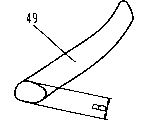
图10为代表性异物的斜视图。Fig. 10 is a perspective view of a representative foreign object.

图11为表示该餐具清洗机中使用的固定喷嘴的主要构成部分截面图。Fig. 11 is a sectional view showing main components of a fixed nozzle used in the dishwasher.

图12为表示该餐具清洗机中使用的其他清洗装置的主要构成部分截面图。Fig. 12 is a sectional view showing main components of another washing device used in the dishwasher.

图13为表示该餐具清洗机中使用的其他清洗装置的主要构成部分截面图。Fig. 13 is a sectional view showing main components of another washing device used in the dishwasher.

图14为本实用新型的实施例2中的餐具清洗机的分水装置的分解斜视图。Fig. 14 is an exploded oblique view of the water separating device of the dishwasher in Embodiment 2 of the present utility model.

图15为该餐具清洗机中的分水装置的清洗泵处于工作状态下的截面图。Fig. 15 is a cross-sectional view of the washing pump of the water diverting device in the dish washing machine in a working state.

图16为该餐具清洗机的分水装置中的阀体的仰视图。Fig. 16 is a bottom view of the valve body in the water diverting device of the dishwasher.

图17为该餐具清洗机的分水装置中的清洗泵处于停止状态下的截面图。Fig. 17 is a cross-sectional view of the washing pump in the water separating device of the dishwasher in a stopped state.

图18为该餐具清洗机的分水装置的啮合部件的详细示意图。Fig. 18 is a detailed schematic diagram of the engaging parts of the water separating device of the dishwasher.

图19为该餐具清洗机的分水装置的其他啮合部件的详细示意图。Fig. 19 is a detailed schematic diagram of other engaging components of the water separating device of the dishwasher.

图20为该餐具清洗机的分水装置的其他啮合部件的详细示意图。Fig. 20 is a detailed schematic diagram of other engaging components of the water separating device of the dishwasher.

图21为该餐具清洗机的分水装置的流出口和阀体之间有异物卡住状态的截面图。Fig. 21 is a cross-sectional view of a state where foreign matter is stuck between the outlet of the water diverting device of the dishwasher and the valve body.

图22为该餐具清洗机中的设有弹力施加装置的分水装置的截面图。Fig. 22 is a cross-sectional view of the water separating device provided with the elastic force applying device in the dishwasher.

图23为该餐具清洗机的其他分水装置的截面图。Fig. 23 is a cross-sectional view of another water separating device of the dishwasher.

图24为该餐具清洗机的其他分水装置的截面图。Fig. 24 is a cross-sectional view of other water separating devices of the dishwasher.

图25为该餐具清洗机的其他分水装置的截面图Fig. 25 is a cross-sectional view of other water diversion devices of the dishwasher

图26为实施例3中的餐具清洗机的分水装置的截面图。Fig. 26 is a sectional view of the water diverting device of the dishwasher in the third embodiment.

图27为实施例3中的餐具清洗机的其他分水装置的斜视图。Fig. 27 is a perspective view of other water separating devices of the dishwasher in Embodiment 3.

图28为实施例3的餐具清洗机的其他分水装置的截面图。Fig. 28 is a cross-sectional view of another water separating device of the dishwasher of the third embodiment.

图29为实施例4的餐具清洗机的分水装置的流出口的俯视图。Fig. 29 is a plan view of the outlet of the water diversion device of the dishwasher of the fourth embodiment.

图30为实施例4的餐具清洗机的分水装置的阀体俯视图。Fig. 30 is a top view of the valve body of the water diverting device of the dishwasher of the fourth embodiment.

图31为实施例5的餐具清洗机的主要构成部分分解斜视图。Fig. 31 is an exploded perspective view of the main components of the dishwasher of the fifth embodiment.

图32为本实用新型的实施例6的餐具清洗机的分水装置中的阀体俯视图。Fig. 32 is a top view of the valve body in the water diverting device of the dishwasher according to Embodiment 6 of the present invention.

图33为表示该餐具清洗机的分水装置附近有异物卡住状态的概略示意图。Fig. 33 is a schematic diagram showing a state where a foreign object is stuck near the water distribution device of the dishwasher.

图34为表示该餐具清洗机的阀体移动方向的详细示意图。Fig. 34 is a detailed schematic view showing the moving direction of the valve body of the dishwasher.

图35为异物从该餐具清洗机的分水装置附近脱落时的状态的概略示意图。Fig. 35 is a schematic diagram of a state in which a foreign matter falls off from the vicinity of the water separator of the dishwasher.

图36为表示该餐具清洗机的分水装置的凸筋部分和顶部的关系的部分侧面图。Fig. 36 is a partial side view showing the relationship between the rib portion and the top of the water separator of the dishwasher.

图37为表示该餐具清洗机的分水装置的凸筋部分和顶部的关系的部分侧面图。Fig. 37 is a partial side view showing the relationship between the rib portion and the top of the water separator of the dishwasher.

图38为本实用新型实施例7中的餐具清洗机的分水装置的阀体的俯视图。Fig. 38 is a top view of the valve body of the water diversion device of the dishwasher in Embodiment 7 of the present utility model.

图39为该餐具清洗机的其他分水装置的阀体的俯视图。Fig. 39 is a top view of the valve body of another water diversion device of the dishwasher.

图40为现有餐具清洗机的主要构成部分截面图。Fig. 40 is a sectional view of main components of a conventional dishwasher.

图41为该餐具清洗机的分水装置的截面图。Fig. 41 is a cross-sectional view of the water separating device of the dishwasher.

上述附图中,参考数字22为清洗槽,26为清洗泵,27为清洗装置(清洗喷嘴),29为剩菜滤网,37为分水装置,38为流入口,39为流出口,40为阀体,41为阀体,42为开口部,44为上部啮合部件(啮合部件),45为下部啮合部件(啮合部件),50为付势装置,60为轴部,61为穴部,63为凸筋(接近部件),64为顶部,65为凹部。Among the above-mentioned accompanying drawings, reference numeral 22 is a cleaning tank, 26 is a cleaning pump, 27 is a cleaning device (cleaning nozzle), 29 is a leftover filter, 37 is a water dividing device, 38 is an inlet, 39 is an outlet, and 40 41 is a valve body, 42 is an opening, 44 is an upper engaging part (engaging part), 45 is a lower engaging part (engaging part), 50 is a potential device, 60 is a shaft part, 61 is a hole part, 63 is a rib (approaching part), 64 is a top, and 65 is a recess.

具体实施方式Detailed ways

下面参照附图对本实用新型的实施例进行描述。Embodiments of the utility model are described below with reference to the accompanying drawings.

(实施例1)(Example 1)

如图1~图5中所示,餐具清洗机主机体20中设有通过门21可以开闭的清洗槽22,餐具等被清洗物23安放在餐具筐24中以后放置到清洗槽22中。进水阀25向清洗槽22中供给洗涤水。清洗泵26将洗涤水加压后,供给设有多个喷射孔的清洗装置(清洗喷嘴)27,该清洗装置27将洗涤水喷射出去。清洗装置27中在4个位置上设有从餐具筐24的下方喷射的喷嘴27a、27b、从右上方喷射的喷嘴27c、从左侧面喷射的喷嘴27d等,这些喷嘴为因射流作用而绕轴转动的转动喷嘴。As shown in FIGS. 1-5 , the main body 20 of the dishwasher is provided with a cleaning tank 22 that can be opened and closed through a door 21 . The water inlet valve 25 supplies washing water into the washing tank 22 . Washing pump 26 pressurizes the washing water, and supplies it to washing device (washing nozzle) 27 provided with a plurality of spray holes, and this washing device 27 sprays washing water. In the cleaning device 27, nozzles 27a, 27b sprayed from the bottom of the tableware basket 24, nozzles 27c sprayed from the upper right, nozzles 27d sprayed from the left side, etc. are provided at four positions. Spinning nozzle with shaft rotation.

清洗槽22的底部设有与清洗泵26的吸入侧相连通的排水口28,该排水口28上设有用来收集剩菜的剩菜滤网29和加热用的加热装置30,且设有检测清洗槽22的温度的温度传感器31。排水泵32用于将清洗槽22内的洗涤水排出。鼓风机33经送风通路34向清洗槽22内送入空气,其排气从排气口35排出。The bottom of cleaning tank 22 is provided with the drain port 28 that communicates with the suction side of cleaning pump 26, and this drain port 28 is provided with the leftovers filter screen 29 that is used to collect leftovers and the heating device 30 that heats usefulness, and is provided with detection. A temperature sensor 31 for the temperature of the cleaning tank 22 . The drain pump 32 is used to drain the washing water in the washing tank 22 . The blower 33 sends air into the cleaning tank 22 through the air supply passage 34 , and the exhaust gas is discharged from the exhaust port 35 .

清洗泵26的出水通路36上设置有用于将供给洗涤水的清洗装置27进行选择切换的分水装置37,该分水装置37的结构如图3及图4中所示,由供被清洗泵26加压了的洗涤水流入的流入口38、具有与4个清洗装置27分别连通的4个流出口39的阀壳40、和设在阀壳40内的可以转动的阀体41所构成,阀体41上设有让洗涤水通过的开口部42。The outlet channel 36 of the cleaning pump 26 is provided with a water dividing device 37 for selectively switching the cleaning device 27 supplying washing water. 26 The inflow port 38 for the pressurized washing water to flow in, the valve case 40 having four outflow ports 39 communicated with the four cleaning devices 27 respectively, and the rotatable valve body 41 provided in the valve case 40 are formed. The valve body 41 is provided with an opening 42 through which washing water passes.

4个流出口39通过各自的清洗通路43与清洗装置27相连结。另外,还设有为使与开口部42相连通的流出口39发生切换而驱动阀体41转动的驱动电机(电动驱动源)54,该驱动电机54的电机轴55在保持着间隙的状态下与阀体41保持传动联结。The four outflow ports 39 are connected to the cleaning device 27 through respective cleaning passages 43 . In addition, a drive motor (electric drive source) 54 that drives the valve body 41 to rotate for switching the outlet 39 communicating with the opening 42 is also provided, and the motor shaft 55 of the drive motor 54 maintains a gap. Keep transmission connection with the valve body 41.

另外,图3等附图只是概念性示图,实际的阀壳40的结构是分成上下2部分,通过螺钉固定、插入联结、焊接及溶接等方式结合在一起。另外,在清洗槽22是由树脂制成等场合下,也可以用清洗槽22的底面来构成与之形成一体的阀壳40的一部分。In addition, the drawings such as FIG. 3 are only conceptual diagrams. The actual structure of the valve housing 40 is divided into upper and lower parts, which are combined by means of screw fixing, insertion connection, welding and welding. In addition, when the cleaning tank 22 is made of resin, etc., the bottom surface of the cleaning tank 22 may constitute a part of the valve case 40 integrally formed therewith.

首先对上述构成中的餐具清洗机的基本操作进行说明。将餐具等被清洗物23装到餐具筐24中,放入清洗槽22中。在放入洗涤剂后,关上门21,将餐具清洗机主机体20的开放部分关闭,开始清洗操作。依次执行洗掉清洗物23上的污物的清洗步骤、冲洗掉附着的洗涤剂及剩菜的冲洗步骤以及使附着在清洗物23上的水滴干燥的干燥步骤。First, the basic operation of the dishwasher in the above configuration will be described. Put the objects to be cleaned 23 such as tableware into the tableware basket 24 and put them into the washing tank 22 . After putting in the detergent, close the door 21, close the opening part of the main body 20 of the dishwasher, and start the washing operation. A washing step of washing off dirt on the object to be cleaned 23 , a rinsing step of rinsing off attached detergent and leftovers, and a drying step of drying water droplets adhering to the object to be cleaned 23 are performed in sequence.

首先,进水阀25打开,向清洗槽22中注入规定量的洗涤水,清洗泵26将洗涤水加压后,从清洗装置27将洗涤水喷射出来。此时,设在清洗槽22内的铠装式加热器等加热装置30被通电,一边使洗涤水加热,一边进行清洗过程。另外,温度传感器31对清洗槽22的温度进行检测,当温度为规定值以上时,则停止向加热装置30通电。First, the water inlet valve 25 is opened, and a predetermined amount of washing water is poured into the washing tank 22. After the washing water is pressurized by the washing pump 26, the washing water is sprayed out from the washing device 27. At this time, a heating device 30 such as a sheath heater provided in the washing tank 22 is energized to perform the washing process while heating the washing water. In addition, the temperature sensor 31 detects the temperature of the washing tank 22, and when the temperature is equal to or higher than a predetermined value, the power supply to the heating device 30 is stopped.

洗涤水在通过剩菜滤网29后被吸入到清洗泵26中,然后由清洗泵26供给到设在清洗槽22内底部上的清洗装置(清洗喷嘴)27中。接着,洗涤水从清洗装置27喷射出来,将餐具等被清洗物23清洗后再回到排水口28,再以上面的通路进行循环。此时,从被清洗物23上被洗下来的剩菜等与洗涤水一起流入剩菜滤网29中,通不过剩菜滤网29的大剩菜被剩菜滤网29捕集起来。The washing water is sucked into the washing pump 26 after passing through the leftovers filter 29 , and is supplied by the washing pump 26 to a washing device (washing nozzle) 27 provided on the inner bottom of the washing tank 22 . Then, the washing water is sprayed out from the cleaning device 27, and returns to the drain port 28 after cleaning the objects 23 to be cleaned such as tableware, and then circulates through the above passage. At this time, the leftovers and the like washed off from the object to be cleaned 23 flow into the leftovers filter screen 29 together with the washing water, and the large leftovers that do not pass through the leftovers filter screen 29 are caught by the leftovers filter screen 29 .

规定时间的清洗步骤结束后,含有污物的洗涤水被排水泵32排向机外,再注入新的洗涤水。清洗泵26再次开始工作,从清洗装置27再次喷射出洗涤水,将附着在清洗物23上的洗涤剂及残菜等物冲洗干净。在经过规定时间的操作之后,将洗涤水排出,再次注入洗涤水。这样的操作反复进行,冲洗步骤连续进行3次左右。最后,将洗涤水排到机外,冲洗步骤完成。After the cleaning step of the specified time is finished, the washing water containing dirt is discharged to the outside of the machine by the drain pump 32, and then new washing water is injected. The washing pump 26 starts to work again, and the washing water is jetted out from the washing device 27 again, so as to rinse away the detergent, residual vegetables and the like attached to the washing object 23 . After the operation for a predetermined time, the washing water is drained, and the washing water is injected again. Such operations are repeated, and the rinsing step is continuously performed about 3 times. Finally, the washing water is discharged out of the machine, and the rinsing step is completed.

接着进行干燥步骤,使鼓风机33工作,将外气通过送风通路34送入清洗槽22内,再从排气口35排出。此时,加热装置30被通电,通过鼓风和加热两方面的效果促使附着在清洗物23上的水滴蒸发。干燥步骤在进行规定的时间后,结束操作。Then carry out the drying step, make the blower 33 work, and the outside air is sent into the cleaning tank 22 through the air supply passage 34, and then discharged from the exhaust port 35. At this time, the heating device 30 is energized, and the water droplets adhering to the object 23 to be cleaned are evaporated through the two effects of blowing air and heating. After the drying step is carried out for a predetermined time, the operation is terminated.

接下来,对本实施例的特征性构成部分即分水装置37的操作、作用进行描述。如图4中所示,阀壳40略呈圆筒形,其轴线方向被大致设置在铅直方向上,供由清洗泵26加压过的洗涤水流入的流入口38设在阀壳40的下端,流出口39设置在阀壳40的上表面上。阀体41略呈平板形状,其中设有流出口39的面A(与阀体41相对的面)为平面形状。Next, the operation and action of the water diversion device 37 which is a characteristic component of this embodiment will be described. As shown in FIG. 4 , the valve casing 40 is roughly cylindrical, and its axial direction is generally arranged in the vertical direction. The inflow port 38 for the washing water pressurized by the cleaning pump 26 is arranged at the lower end of the valve casing 40. , the outflow port 39 is provided on the upper surface of the valve housing 40 . The valve body 41 is substantially in the shape of a flat plate, and the surface A (the surface opposite to the valve body 41 ) on which the outlet 39 is provided has a flat shape.

阀体41和电机轴55以保持着一定间隙的状态互相保持传动,阀体41除了转动动作以外在上下方向上也可以移动,相对于流出口39可以进退自如。在清洗泵26工作时,在从流入口38流入的洗涤水的压力作用下阀体41上升,靠近流出口39。驱动电机54使阀体41转动,与开口部42位置一致的流出口39中将有洗涤水供给,与该流出口39连通的清洗装置27中将有洗涤水被喷射出来。The valve body 41 and the motor shaft 55 maintain transmission with each other while maintaining a certain gap. The valve body 41 can also move up and down in addition to rotating, and can freely advance and retreat relative to the outlet 39 . When the cleaning pump 26 is in operation, the valve body 41 rises under the pressure of the washing water flowing in from the inlet 38 and approaches the outlet 39 . The drive motor 54 rotates the valve body 41, and the outlet 39 at the same position as the opening 42 will be supplied with washing water, and the cleaning device 27 connected with the outlet 39 will be sprayed with washing water.

通过使阀体41转动,可以依次切换有洗涤水供给的流出口39,并且使喷射洗涤水的清洗装置27以27a、27b、27c、27d的顺序进行切换。此时,驱动电机54的驱动方法有连续驱动方法、使开口部42在流出口39的位置上停住的断续驱动方法等,而且还不限于这两种。By rotating the valve body 41, the outflow port 39 to which the washing water is supplied can be sequentially switched, and the washing device 27 spraying the washing water can be switched in the order of 27a, 27b, 27c, and 27d. At this time, the driving method of the driving motor 54 includes a continuous driving method, an intermittent driving method of stopping the opening portion 42 at the position of the outlet 39, and the like, and is not limited to these two methods.

另外,在采用前一种方法的场合下,无须检测阀体41的位置的传感器等部件,结构比较简单;在采用后一种方法的场合下,虽然需要位置传感器等器件,但切换效率高,可以根据情况来有选择地设定清洗装置27的位置及喷射时间。In addition, in the case of the former method, there is no need to detect parts such as sensors for the position of the valve body 41, and the structure is relatively simple; in the case of the latter method, although devices such as position sensors are required, the switching efficiency is high. The position and spraying time of the cleaning device 27 can be selectively set according to the situation.

在上述装置的作用下,洗涤水不用同时供给4处清洗装置27,而是依次供给洗涤水,故不会使供水量增加,对于任一被清洗物23都可以从多个方向喷射洗涤水。因此,可以在短时间内清洗掉附着在餐具等被清洗物23上的污浊物,实现高效率的清洗。Under the effect of above-mentioned device, washing water does not need to supply 4 cleaning devices 27 at the same time, but supplies washing water sequentially, so the water supply volume will not be increased, and washing water can be sprayed from multiple directions for any object 23 to be cleaned. Therefore, the dirt adhering to the object 23 to be cleaned such as tableware can be cleaned in a short time, and efficient cleaning can be realized.

另外,由于附着在餐具等被清洗物23上的洗涤剂及剩菜在短时间内就可以冲洗干净,故可以减少冲洗次数。例如,可以将原来进行4次的减少为3次。每一次的供水量也不会增加,而且由于次数削减了,用加热装置30对洗涤水进行加热的时间也能够缩短,从而可以达到省能源、省水的效果。In addition, since the detergent and leftovers adhering to the objects to be cleaned 23 such as tableware can be washed away in a short time, the number of times of washing can be reduced. For example, the original 4 times can be reduced to 3 times. The amount of water supplied each time will not increase, and because the number of times is reduced, the time for heating the washing water by the heating device 30 can also be shortened, thereby saving energy and water.

另外,由于是在不增大进水量的前提下增加了清洗喷嘴27的数量,从而可以采用相对于餐具等被清洗物23从多个方向喷射洗涤水的清洗方式。这样,用户在将被清洗物23放入餐具筐24中时不用考虑放置的位置、纵放、横放等方式,可以自由地进行安放,可以得到安放性更为优异地餐具清洗机。而且即使对于方型小碗、较深的小碗、方形盘子等靠单一方向的喷射洗涤水不能充分地清洗干净的餐具而言,也能够充分地发挥清洗性能。In addition, since the number of washing nozzles 27 is increased without increasing the water intake, a washing method in which washing water is sprayed from multiple directions with respect to the object 23 to be washed such as tableware can be adopted. In this way, when the user puts the object to be cleaned 23 into the dish basket 24, it can be placed freely without considering the position, vertical placement, or horizontal placement, and can obtain a dishwasher with better placement properties. Moreover, even for tableware such as small square bowls, deep small bowls, and square plates that cannot be sufficiently cleaned by spraying washing water in one direction, the cleaning performance can be fully exhibited.

另外,从一个地方的清洗装置27喷射的时间可以在数秒至1分钟左右进行切换,这样可以进行高效率的清洗。但最好是在每1次的清洗或者冲洗过程中设定让所有的清洗装置27至少进行1次喷射。因此,上述的喷射时间可以设定为10秒至30秒左右。In addition, the spraying time from one cleaning device 27 can be switched from a few seconds to about one minute, so that efficient cleaning can be performed. But it is preferable to set all the cleaning devices 27 to spray at least once during each cleaning or flushing process. Therefore, the above-mentioned injection time can be set to about 10 seconds to 30 seconds.

由于阀体41是由驱动电机(电动驱动源)54进行驱动的,故能可靠地使阀体41转动,从而可靠地切换供给洗涤水的清洗装置27。Since the valve body 41 is driven by the driving motor (electric drive source) 54, the valve body 41 can be reliably rotated, thereby reliably switching the washing device 27 for supplying washing water.

另外,如图5中所示,阀体41还可以移动,从设有流出口39的面A上离开。也就是说,阀体41可以向下移动,即使在清洗泵26工作时,也可以进行这样的移动。由于剩菜及牙签等异物49会混在洗涤水中一起循环,如图6中所示,当因开口部42的转动而与流出口39之间的间隙越来越小时,异物49有时正好会夹入其中。阀体41如果不与流出口39分离,有些种类的异物49会使阀体41卡死,造成不能切换。当驱动电机54的驱动力很强的情况下,还可能造成阀体41及流出口39损坏。In addition, as shown in FIG. 5 , the valve body 41 can also move away from the surface A on which the outlet 39 is provided. That is, the valve body 41 can move downward even when the washer pump 26 is in operation. Because foreign objects 49 such as leftovers and toothpicks can be mixed in the washing water and circulate together, as shown in Fig. in. If the valve body 41 is not separated from the outlet 39, some kinds of foreign matter 49 will cause the valve body 41 to be stuck, resulting in inability to switch. When the driving force of the driving motor 54 is very strong, the valve body 41 and the outlet 39 may be damaged.

因此,在本实用新型中,阀体41由于被设置成能与设有流出口39的面A分离,能象图7中所示的那样移动,故能够避免异物49卡入,能使转动驱动不受影响。当有异物49卡入时,所有的清洗装置27都有洗涤水供给,但此时的洗涤水供给是不充足的,当转到下一个流出口39的位置上时,异物49被冲掉,从而能够再次正常地进行洗涤水切换,高效地清洗被清洗物。Therefore, in the utility model, the valve body 41 can be moved as shown in Fig. 7 because it is set to be separated from the surface A provided with the outlet 39, so that foreign matter 49 can be avoided and the rotation can be driven. Not affected. When a foreign matter 49 is stuck in, all cleaning devices 27 have washing water supply, but the washing water supply at this moment is insufficient, and when turning to the position of the next outlet 39, the foreign matter 49 is washed away, Therefore, the washing water can be switched normally again, and the objects to be cleaned can be cleaned efficiently.

另外,异物49可以是各种各样的东西,除了食品以外还可能是鱼骨、牙签、橡皮圈、塑料纸或餐具破片等等。特别是牙签及樱桃的茎等细长的物品,不管其长度如何,由于可能穿过剩菜滤网,故对于这样的异物也要有必要的对应措施。In addition, the foreign matter 49 can be various things, besides food, it may also be a fishbone, a toothpick, a rubber ring, plastic paper, or pieces of cutlery. In particular, slender objects such as toothpicks and cherry stems may pass through the leftovers filter regardless of their length, so countermeasures are necessary for such foreign objects.

上述那些卡住的异物49在转过一个或数个流出口39后,一般能够清除掉,但也有细长的异物不易清除的情况。为此,使清洗泵26中途临时停止时,在停止时阀体41在其自重作用下与流出口39分离,使卡住的异物49清除掉。这样,就不会发生异物49卡入间隙中造成阀体41不能转动的情况,从而可以可靠地进行阀体41的切换。The above-mentioned stuck foreign matter 49 can generally be removed after turning over one or several outlets 39, but there are also cases where the elongated foreign matter is difficult to remove. For this reason, when the washing pump 26 is temporarily stopped halfway, the valve body 41 is separated from the outlet 39 by its own weight during the stop, and the stuck foreign matter 49 is removed. In this way, the situation that the valve body 41 cannot be rotated due to foreign objects 49 being caught in the gap will not occur, so that the switching of the valve body 41 can be performed reliably.

由于清洗泵26至少会在清洗及冲洗步骤结束时停止,就这一次清洗而言,因切换不良造成清洗性能下降的可能性是存在的,但从下一次的使用开始,使用起来就不会有问题。另外,在清洗及冲洗步骤的中途使清洗泵26临时停止几次的话,可以将切换不良的次数抑制到最小限度,从而可以抑制清洗性能的下降。Since the cleaning pump 26 will stop at least at the end of the cleaning and rinsing steps, for this cleaning, there is a possibility that the cleaning performance will decline due to poor switching, but from the next use, it will not be used. question. In addition, if the cleaning pump 26 is temporarily stopped several times in the middle of the cleaning and rinsing steps, the number of switching failures can be suppressed to a minimum, and a decrease in cleaning performance can be suppressed.

另外,如图7所示,阀体41相对于其直线运动的方向即上下方向可以倾斜。从上方观察以电机轴55处为截面的阀体41和电机轴55的传动部分时,可以看到,电机轴55和阀体41之间如图8中所示的那样设有间隙41a,在所有的方向上都可以倾斜。In addition, as shown in FIG. 7 , the valve body 41 may be inclined relative to the direction of its linear motion, that is, the up and down direction. When observing the transmission part of the valve body 41 and the motor shaft 55 taking the motor shaft 55 as a section from above, it can be seen that a gap 41a is provided between the motor shaft 55 and the valve body 41 as shown in Figure 8, and Can be tilted in all directions.

这样一来,在有异物49卡住的情况下阀体41也能顺利地移动。另外,在流出口39与开口部42的接触部分的端面上可以进行倒角、圆角等处理,这样可使阀体41的分离操作更加顺利地进行。In this way, the valve body 41 can move smoothly even when a foreign object 49 is stuck. In addition, the end surface of the contact portion of the outlet 39 and the opening 42 can be chamfered, rounded, etc., so that the separation operation of the valve body 41 can be performed more smoothly.

另外,即使在流出口39和阀体41的部分间隙中有异物49卡住,由于洗涤水的压力等的作用在阀体41上施加上了倾斜的力的场合下,也可以防止阀体41象橇棒似的卡在阀壳40等中、使阀体41不能切换的情况的发生。In addition, even if a foreign object 49 is stuck in a part of the gap between the outlet port 39 and the valve body 41, the valve body 41 can be prevented from being damaged when an inclined force is applied to the valve body 41 due to the pressure of washing water, etc. Like a sled stick stuck in the valve case 40, etc., so that the valve body 41 cannot be switched.

这样一来,阀体41及阀壳40不会发生损坏的倾斜角度可以设定为能倾斜成比与剩菜滤网29的间隙同样大小的异物49卡住时的倾斜角度更大的角度。另外,阀体41和电机轴55之间的连结可以采用万向节,当然用类似的方式也可以起到同样的效果。In this way, the inclination angle at which the valve body 41 and the valve housing 40 will not be damaged can be set to an angle larger than the inclination angle at which a foreign object 49 of the same size as the gap of the leftover filter 29 is caught. In addition, the connection between the valve body 41 and the motor shaft 55 can be a universal joint, and of course a similar method can also achieve the same effect.

另外,在清洗泵26开始工作的瞬间阀壳40和阀体4 1之间有异物49卡住的情况下,所有的清洗装置27都将被供给洗涤水,洗涤水的供给可能是不充足的,但清洗泵26临时停止时,流出口39和阀体41之间的距离将变大,异物49将被除去,清洗泵26再次开始工作时就能毫无问题地进行切换,从而能高效率地将被清洗物23清洗干净。In addition, when the cleaning pump 26 starts to work, if there is a foreign object 49 stuck between the valve housing 40 and the valve body 41, all cleaning devices 27 will be supplied with washing water, and the supply of washing water may be insufficient. , but when the cleaning pump 26 is temporarily stopped, the distance between the outlet 39 and the valve body 41 will be increased, the foreign matter 49 will be removed, and the cleaning pump 26 can be switched without any problem when it starts working again, so that high efficiency can be achieved. The object 23 to be cleaned is thoroughly cleaned.

另外,如图9所示,当清洗泵26停止工作时,为了使阀体41与流出口39分离,还可以设置弹力施加装置50,在阀体41施加上从流出口39分离方向上的弹力。这样在阀壳40和阀体41之间有异物49卡入、清洗泵26停止工作的状态下,可以防止阀体41不能与流出口39分离的情况的发生,从而可以在停止工作状态下可靠地将异物49除去。In addition, as shown in Figure 9, when the cleaning pump 26 stops working, in order to separate the valve body 41 from the outlet 39, an elastic force applying device 50 can also be provided to apply an elastic force on the valve body 41 in the direction of separating from the outlet 39. . In this way, when there is a foreign matter 49 stuck between the valve housing 40 and the valve body 41, and the cleaning pump 26 stops working, it can prevent the valve body 41 from being separated from the outlet 39, so that it can be reliably operated in the stopped working state. The foreign matter 49 is removed.

采用上述结构后,无论阀体41设置在什么方向上,都可以与流出口39分离,从而具有分水装置37可以设置在任何角度(方向)上的优点。另外,弹力施加装置50除了图示的圈簧之外,还可以使用板簧、橡胶等弹性体。After adopting the above structure, no matter in which direction the valve body 41 is arranged, it can be separated from the outflow port 39, thus having the advantage that the water diversion device 37 can be arranged in any angle (direction). In addition, elastic bodies such as leaf springs and rubber may be used for the elastic force applying device 50 other than the illustrated coil springs.

另外,在清洗泵26工作状态下,在阀壳40内的压力作用下阀体41被向流出口39一侧即向上方被加压,阀体41与流出口39的密封面之间的紧密接触程度得到增强,洗涤水的泄漏可以极大地减少,使更多的洗涤水被从清洗装置27喷射出来,清洗性能能进一步得到提高。如果阀体41及流出口39在水压作用下可以变形的话,则上述密封性能可以进一步得到提高。In addition, when the cleaning pump 26 is working, the valve body 41 is pressurized to the side of the outlet 39 under the action of the pressure in the valve casing 40, that is, upward, and the sealing surface between the valve body 41 and the outlet 39 is tightly sealed. The degree of contact is enhanced, and the leakage of wash water can be greatly reduced, so that more wash water is sprayed from the washing device 27, and the washing performance can be further improved. If the valve body 41 and the outlet 39 can be deformed under the action of water pressure, the above-mentioned sealing performance can be further improved.

另外,在清洗泵26工作期间,阀壳40内通常被加压至20~40kPa左右,作用在阀体41的力虽因其大小不同而不通,但通常大致为20~100N左右,从而将其牢固地按压在流出口39上。In addition, during the operation of the cleaning pump 26, the inside of the valve casing 40 is usually pressurized to about 20-40kPa, and the force acting on the valve body 41 is generally about 20-100N, although the force acting on the valve body 41 is different due to its size, so that it Press firmly on spout 39.

另一方面,在阀体41由洗涤水加压的状态下,阀体41转动时将产生很大的摩擦,阀体41及流出口39会有被磨损的危险。通过在驱动电机54工作时使清洗泵26停止工作,可以解决这一问题。在清洗泵26停止时驱动阀体41转动,直至到达下一个规定位置,然后使驱动电机54停止工作而让清洗泵26再次工作。这样,阀体41只会紧靠在流出口39上,不会发生滑动,因此几乎不产生摩损。On the other hand, in the state where the valve body 41 is pressurized by washing water, great friction will be generated when the valve body 41 rotates, and the valve body 41 and the outlet 39 may be worn. This problem can be solved by deactivating the washer pump 26 while the drive motor 54 is operating. When the cleaning pump 26 stops, the valve body 41 is driven to rotate until it reaches the next specified position, and then the driving motor 54 is stopped to allow the cleaning pump 26 to work again. In this way, the valve body 41 will only abut against the outlet 39 without sliding, so there is almost no friction.

这样,分水装置37的寿命及可靠性可以得到提高。另外,即使清洗泵26和驱动电机54在部分时间同时工作的话,只要不造成摩损,就没有必要让清洗泵26完全停止。In this way, the life and reliability of the water dividing device 37 can be improved. In addition, even if the washer pump 26 and the drive motor 54 are operated partly at the same time, it is not necessary to completely stop the washer pump 26 as long as no wear is caused.

另外,虽然希望流出口39和阀体41之间能够紧密贴合,但即使因部件的尺寸精度等原因造成细微的间隙存在,或者将微少间隙设定在1mm以下的场合下,虽然向其他流出口39稍微有一些漏水,但分水装置37能过充分地起到分水功能。In addition, although it is desirable that the outflow port 39 and the valve body 41 can be in close contact, even if there is a slight gap due to the dimensional accuracy of the parts, or if the slight gap is set to be less than 1mm, although the flow to the other flow The outlet 39 has some water leakage a little, but the water diversion device 37 can fully play the water diversion function.

另外,阀体41离开流出口39的距离为剩菜滤网29中的间隙以上,这样在流出口39和阀体41之间可以形成比可能穿过剩菜滤网29流入分水装置37中的异物49的尺寸要大的间隙,故在清洗泵26停止工作期间,卡在其中的异物49能够去除,从而可以提供总是能保持高可靠性的分水装置37。In addition, the distance between the valve body 41 and the outflow port 39 is more than the gap in the leftovers filter screen 29, so that a ratio may be formed between the outflow port 39 and the valve body 41 and may pass through the leftovers filter screen 29 and flow into the water dividing device 37. The size of the foreign matter 49 requires a large clearance, so the foreign matter 49 stuck therein can be removed during the stoppage of the cleaning pump 26, thereby providing the water separating device 37 that can always maintain high reliability.

另外,上述的“剩菜滤网29的间隙以上”中的间隙是指相当于圆孔直径、网孔边长等尺寸。严格地说,是在如图10中所示的可能穿过剩菜滤网29的异物49的最小尺寸B以上。另外,剩菜滤网29有时包括固定在排水口28上的不可拆下的固定滤网51和可以拆下进行清扫的可装拆滤网52这2个滤网。只要按照其中间隙小的一方的尺寸(通常是可装拆滤网52)进行设定的话,通常工作时就不会有问题。但是,由于存在可装拆滤网52被装错或忘记安装等可能性,设定成远大于固定滤网51的间隙的距离的话比较可靠。In addition, the gap in the above-mentioned "more than the gap of the leftovers filter 29" refers to dimensions corresponding to the diameter of the circular hole, the side length of the mesh, and the like. Strictly speaking, it is above the minimum size B of the foreign matter 49 that may pass through the leftovers filter 29 as shown in FIG. 10 . In addition, the leftovers filter 29 may include two filters of a non-detachable fixed filter 51 fixed to the drain port 28 and a detachable filter 52 detachable for cleaning. As long as it is set according to the size of the side where the gap is small (usually the detachable filter screen 52), there will be no problem during normal work. However, since there is a possibility that the detachable filter screen 52 is installed incorrectly or forgotten to be installed, it is more reliable to set it to a distance far greater than the gap of the fixed filter screen 51 .

另外,阀壳40和阀体41之间的最小间隙设定大于为所述剩菜滤网29的间隙。阀壳40和阀体41之间的间隙是指阀体41的外圆周及端面至阀壳40的直线距离。另外,剩菜滤网29的间隙以上的意思和上面的相同。这样一来,由于在流出口39和阀体41之间存在着比可能流入分水装置37的异物49的尺寸大的间隙,故能够防止异物49卡入这些间隙中、造成阀体41不能切换的情况发生。In addition, the minimum gap between the valve casing 40 and the valve body 41 is set to be larger than the gap of the leftover filter 29 . The gap between the valve housing 40 and the valve body 41 refers to the linear distance from the outer circumference and end surface of the valve body 41 to the valve housing 40 . In addition, the meaning above the gap of the leftovers filter 29 is the same as above. In this way, since there is a gap between the outlet 39 and the valve body 41 that is larger than the size of the foreign matter 49 that may flow into the water diversion device 37, it is possible to prevent the foreign matter 49 from being stuck in these gaps, causing the valve body 41 to fail to switch. situation occurs.

另外,使用对哪个的清洗装置27被供给了洗涤水进行检测的检测装置(图中未示出)的话,还可以改变各个清洗装置27的喷射时间,进行更高效率的清洗。举例来说,为了提高对于比较难洗的饭碗的清洗能力,将从清洗装置27a的喷射时间设置成比其他装置时间长一些是很有效果的。In addition, if a detection device (not shown) for detecting which washing device 27 is supplied with washing water is used, the spraying time of each washing device 27 can be changed to perform more efficient washing. For example, in order to improve the cleaning ability for relatively difficult rice dishes, it is very effective to set the spraying time from the cleaning device 27a to be longer than that of other devices.

检测装置可以包括检测阀体41的转动位置的装置、检测清洗通路43内的压力或者流水的有无的装置等好多种。另外,没有必要在4个地方设置上传感器。只要在1个地方设置上传感器,再结合清洗泵26的工作/停止、转速等信息的话,就可以知道是从哪个位置喷射出洗涤水的。The detection device may include a device for detecting the rotational position of the valve body 41 , a device for detecting the pressure in the cleaning passage 43 or the presence or absence of running water, and many others. Also, there is no need to install upper sensors at four places. As long as a sensor is installed at one place, and combined with information such as operation/stop and rotation speed of the washing pump 26, it can be known from which position the washing water is sprayed.

另外,在被清洗物23的量较少等没有必要从所有的清洗装置27喷射洗涤水的场合下,可以将不必要的清洗装置27的喷射时间设定为1秒以下的极短时间,使它们几乎不发生喷射,而只让必要的清洗装置27进行喷射。这样,可以以更高的效率进行清洗,以期缩短工作时间。另外,通过使冲洗过程中的最终喷射由设在餐具筐24上方的清洗装置27c来进行,可以尽可能地减少附着在被清洗物上的微细水滴,进一步提高清洗性能。In addition, when the amount of the object to be cleaned 23 is small, etc., it is not necessary to spray washing water from all the cleaning devices 27, the spraying time of the unnecessary cleaning devices 27 can be set to a very short time of 1 second or less, so that They hardly spray, but only allow the necessary cleaning device 27 to spray. In this way, cleaning can be carried out with higher efficiency in order to shorten the working time. In addition, by making the final spraying during the rinsing process be performed by the cleaning device 27c above the tableware basket 24, the fine water droplets adhering to the object to be cleaned can be reduced as much as possible, and the cleaning performance can be further improved.

另外,本实施例中,在4个地方设置有清洗装置27,而且全部是可以转动的转动喷嘴。但是,也可以不限定为4处,也可以根据餐具筐24中的餐具配置来设定清洗装置27的个数。虽然只要在2处以上就可以发挥效果,但是考虑到对于所有的餐具都能收到2个方向以上的喷射对于提高清洗性能是非常重要的这一事实,最好设置成4处以上。In addition, in this embodiment, cleaning devices 27 are provided at four places, and all of them are rotating nozzles that can rotate. However, it is not limited to four locations, and the number of cleaning devices 27 may be set according to the arrangement of dishes in the dish basket 24 . Although the effect can be exhibited as long as there are two or more places, considering the fact that it is very important to improve the cleaning performance to receive jets in two or more directions for all the tableware, it is better to set it at four or more places.

反过来说,分路数太多时,从1个的清洗装置27喷射出的总水量会减小,清洗效果反而会不佳。因此,最好是设置在10处以下,特别是6处以下。Conversely, when the number of branches is too large, the total amount of water sprayed from one cleaning device 27 will decrease, and the cleaning effect will be poor instead. Therefore, it is best to set it below 10 places, especially below 6 places.

另外,清洗装置中使用转动喷嘴的话确实能提高清洗性能,但也存在着清洗装置27所占的空间增大、主机体的外机壳尺寸相同的情况下收容被清洗物23的部分的容积会减少的问题。因此,如图11中所示的那样,设置在背面及上方的清洗喷嘴选用不转动的固定式清洗装置27c、27d是能解决上述问题的有效办法。这里的转动喷嘴及固定喷嘴等的设置方式及其喷射口的个数都不是限制性的规定。In addition, if the rotating nozzle is used in the cleaning device, the cleaning performance can indeed be improved, but there is also the fact that the occupied space of the cleaning device 27 increases, and the volume of the part for accommodating the object 23 to be cleaned will decrease when the outer casing size of the main body is the same. reduced problem. Therefore, as shown in Figure 11, it is an effective way to solve the above-mentioned problems that the cleaning nozzles arranged on the back side and the top use non-rotating fixed cleaning devices 27c, 27d. Here, the arrangement of the rotating nozzle, the fixed nozzle, etc., and the number of injection ports are not restrictive.

另外,还可以根据餐具清洗机主机体20的形状及餐具配置等对清洗装置27进行最佳地设定,可使清洗性能进一步得到提高。比方说,可以象图12那样在27a,27b,27e等3处配置清洗装置27,或者象图13那样,将餐具筐24分成上下2层,在上下层的筐24的中间部分上设置2个转动喷嘴27c,27d等。In addition, the cleaning device 27 can also be optimally set according to the shape of the main body 20 of the dishwasher and the arrangement of the dishes, so that the cleaning performance can be further improved. For example, the cleaning device 27 can be arranged at 27a, 27b, 27e, etc. as shown in Figure 12, or as shown in Figure 13, the tableware basket 24 is divided into upper and lower layers, and two baskets are arranged in the middle of the upper and lower baskets 24. Rotate nozzles 27c, 27d, etc.

另外,虽然在上面的描述中多个清洗装置27中在某一时刻进行喷射的清洗装置27只有1处,但也可以通过在阀体41上设置2处或更多的开口部42,使多个清洗装置27同时喷射,对其位置进行切换也是可以的。In addition, although there is only one cleaning device 27 that sprays at a certain moment in the plurality of cleaning devices 27 in the above description, it is also possible to set two or more openings 42 on the valve body 41 so that multiple A cleaning device 27 sprays simultaneously, and it is also possible to switch its position.

另外,将多个流出口39中的1个与向机外排出洗涤水的排出通路相连结的话,可以不用排水泵32就能进行排水。这样就没有必要设置排水泵32,可以降低成本,使装置小型化。In addition, if one of the plurality of outflow ports 39 is connected to a discharge passage for discharging the washing water to the outside of the machine, drainage can be performed without using the drain pump 32 . In this way, there is no need to provide the drain pump 32, which can reduce the cost and make the device miniaturized.

另外,在清洗过程中依次切换清洗装置27时,洗涤水也肯定会流进上述的那个流出口39,这样只要清洗泵26不断工作在清洗过程中水就会排掉。为此,可以对洗涤水正被供给哪个流出口39进行检测,在排水以外的时间内不向排水用的流出口39供给洗涤水,这样可防止在排水以外的时间向机外排水。另外,通过在排水通路上设置开闭阀,可以可靠地防止洗涤水被排向机外。In addition, when the cleaning device 27 is switched sequentially during the cleaning process, the washing water will definitely flow into the above-mentioned outflow port 39, so that as long as the cleaning pump 26 is continuously working, the water will be drained during the cleaning process. Therefore, it is possible to detect which outflow port 39 the washing water is being supplied to, and not to supply the washing water to the outflow port 39 for draining during non-draining time, so as to prevent water from being discharged outside the machine during non-draining time. In addition, by providing an on-off valve on the drain passage, it is possible to reliably prevent washing water from being drained out of the machine.

另外,本实用新型是有关洗涤水的切换方式的实用新型,对于餐具清洗机主机体20的形状及大小、门21的开闭方式、餐具等被清洗物的配置、各个部件的配置等都没有特别的要求/限定。另外,本实施例中示出的是具有干燥功能的餐具清洗机,对于不具备干燥功能的餐具清洗机也能达到同样的效果。In addition, the utility model is a utility model related to the switching method of the washing water, and has no information on the shape and size of the main body 20 of the dishwasher, the opening and closing method of the door 21, the arrangement of the objects to be cleaned such as tableware, and the arrangement of each component. Special Requirements/Restrictions. In addition, what is shown in this embodiment is a dishwasher with a drying function, and the same effect can be achieved for a dishwasher without a drying function.

(实施例2)(Example 2)

本实施例中的分水装置37的结构如图14、图15所示,和实施例1中一样由设有流入口38和4个流出口39的阀壳40和可以移动的阀体41所构成。阀体41上设有让洗涤水通过的开口部42。但是省掉了驱动阀体41的驱动电机54。作为代替部件,在阀壳40一侧和阀体41一侧分别设置有在阀体41上升时使阀体41转动规定角度的一组上部啮合部件44和阀体41下降时使阀体41转动规定角度的一组下部啮合部件45。The structure of the water dividing device 37 in this embodiment is shown in Figure 14 and Figure 15, and is formed by the valve casing 40 and the movable valve body 41 that are provided with the inlet 38 and four outlets 39 as in Embodiment 1. constitute. The valve body 41 is provided with an opening 42 through which washing water passes. However, the drive motor 54 for driving the valve body 41 is omitted. As an alternative component, a set of upper engaging parts 44 that rotate the valve body 41 at a predetermined angle when the valve body 41 rises and a set of upper engaging parts 44 that rotate the valve body 41 when the valve body 41 descends are respectively provided on the valve housing 40 side and the valve body 41 side. A set of lower engaging members 45 at a prescribed angle.

如图14中所示,阀壳40略呈圆筒形,其轴线方向大致配置在铅直方向上,供经清洗泵26加压的洗涤水流入的流入口38设置在阀壳40下端上,流出口39设置在阀壳40的上表面上。阀体41略呈平面形状,流出口39处与阀体41相对的面A也为平面形状。As shown in FIG. 14 , the valve case 40 is approximately cylindrical, and its axial direction is arranged in the vertical direction. The outlet 39 is provided on the upper surface of the valve housing 40 . The valve body 41 is roughly planar, and the surface A opposite to the valve body 41 at the outflow port 39 is also planar.

当清洗泵26工作时,在从流入口38流入的洗涤水的水流(压力)作用下阀体41沿上部啮合部件44上的斜坡以大致直线运动带有转动的动作向上升起,如图15中所示,在使流出口39开放的规定位置上被固定住,从与该流出口39相连通的清洗装置27将有洗涤水喷射出来。上部啮合部件44(截面图中没有示出啮合部件的详细结构,参照图18)被设定成这样,即从阀体41的正下方观察时,设在阀体41上的让洗涤水流过的位置上的开口部42与上述的流出口39如图16中所示的那样位置互相对齐。When the cleaning pump 26 works, the valve body 41 rises upwards along the slope on the upper engaging part 44 with a substantially linear motion with rotation under the action of the water flow (pressure) of the washing water flowing in from the inflow port 38, as shown in Figure 15 As shown in , it is fixed at a predetermined position where the outflow port 39 is opened, and washing water is sprayed from the washing device 27 communicating with the outflow port 39 . The upper engaging part 44 (the detailed structure of the engaging part is not shown in the cross-sectional view, referring to FIG. 18 ) is set such that when viewed from directly below the valve body 41, the valve body 41 provided on the valve body 41 allows washing water to flow. The positional opening 42 and the aforementioned outflow port 39 are aligned with each other as shown in FIG. 16 .

接下来,使清洗泵26临时停止工作时,将阀体41从下方向上顶起的压力不再起作用,阀体41再其自重作用下下落。但此时阀体41是一边沿下部啮合部件45上的倾斜面转动一边落下,最后停止在图17所示的规定位置上。Next, when the cleaning pump 26 is temporarily stopped, the pressure that pushes up the valve body 41 from below no longer works, and the valve body 41 falls under its own weight. However, at this time, the valve body 41 falls while rotating along the inclined surface on the lower engaging member 45, and finally stops at a predetermined position shown in FIG. 17 .

清洗泵26再次工作时,阀体41与上部啮合部件44的下一个倾斜面啮合,一边转动一边上升,与下一个流出口39相连通,使下一个清洗装置27喷射出洗涤水。这样,通过使清洗泵26断续地工作,就可以使喷射洗涤水的清洗装置27以27a、27b、27c、27d的顺序进行切换,可以起到和实施例1相同的由分水装置37达到很高的清洗效果。When the cleaning pump 26 works again, the valve body 41 engages with the next inclined surface of the upper engaging part 44, rises while rotating, and communicates with the next outflow port 39, so that the next cleaning device 27 sprays washing water. In this way, by making the cleaning pump 26 work intermittently, the cleaning device 27 spraying the washing water can be switched in the order of 27a, 27b, 27c, 27d, and the same effect as that of the first embodiment can be achieved by the water dividing device 37. Very high cleaning effect.

将圆形的上部啮合部件44和下部啮合部件45在平面拉伸后表示出其关系的话,如图18所示的那样,通过清洗泵26的工作/停止的不断重复,阀体41一边进行着上下方向的大致直线运动和转动运动的组合动作,一边依次进行位置变换。另外,在本实施例中,为了使4处的流出口39依次进行切换,经过一次的停止/再工作阀体41转动90度。如图18中所示,上部啮合部件44及下部啮合部件45被设定成,阀体上升时转动约20度,下降时转动约70度。If the relationship between the circular upper engaging member 44 and the lower engaging member 45 is drawn in a plane, as shown in FIG. Combination of approximately linear motion and rotational motion in the up and down directions, while sequentially changing positions. In addition, in this embodiment, in order to sequentially switch the four outflow ports 39, the stop/restart valve body 41 is rotated 90 degrees after one pass. As shown in FIG. 18, the upper engaging member 44 and the lower engaging member 45 are set so that the valve body rotates about 20 degrees when rising and about 70 degrees when descending.

另外,这些啮合部件的形状也不限于螺旋形及三角形等形状,只要在清洗泵26断续地工作时使规定的流出口39和阀体41的开口部42对齐就可以。例如,不制成三角形的爪部形状,而是制成图19中所示的那种导辊47在槽46中移动的结构也是可以的。另外,啮合部件的位置也不限定于阀体41的外围。In addition, the shapes of these engaging members are not limited to spiral and triangular shapes, as long as the predetermined outflow port 39 is aligned with the opening 42 of the valve body 41 when the washer pump 26 is intermittently operated. For example, instead of a triangular claw shape, it is also possible to make a structure in which the guide roller 47 moves in the groove 46 as shown in FIG. 19 . In addition, the position of the engaging member is not limited to the periphery of the valve body 41 .

这样,喷射洗涤水的清洗装置27的切换就可以通过清洗泵26的断续工作来实现,3通阀及电动机等电动驱动机构就可以省去,从而可以降低成本,并且使分水装置37实现小型化。另外,在电机驱动的场合下,由于转动轴需要贯通阀壳40设置,需要设置周密的密封装置,使结构复杂化。同时,密封不良时还有可能向制品外部漏水。而本实用新型的构成中不存在贯通阀壳40工作的部件,不用担心向外部漏水。In this way, the switching of the cleaning device 27 spraying washing water can be realized by the intermittent operation of the cleaning pump 26, and electric drive mechanisms such as 3-way valves and motors can be omitted, thereby reducing costs and making the water dividing device 37 realize miniaturization. In addition, in the case of motor drive, since the rotating shaft needs to be installed through the valve casing 40, a strict sealing device needs to be provided, which complicates the structure. At the same time, when the seal is poor, water may leak to the outside of the product. However, in the composition of the present utility model, there is no working part passing through the valve casing 40, so there is no need to worry about water leakage to the outside.

另外,在清洗泵26工作时的状态下,阀体41在阀壳40内的压力作用下被推向流出口39一侧即被推向上方。这样一来,由于阀体41与流出口39的密封面的密切贴合程度得到增强,洗涤水的泄漏能减少到极其微小的程度,从而可以由清洗装置27喷射出更多的洗涤水,进一步提高清洗性能。如果阀体41或者流出口39在水压作用下可以变形的话,则上述密封性将能进一步提高。In addition, when the cleaning pump 26 is in operation, the valve body 41 is pushed toward the outlet 39 side, that is, upward, by the pressure inside the valve housing 40 . In this way, since the close fit between the valve body 41 and the sealing surface of the outlet 39 is enhanced, the leakage of washing water can be reduced to an extremely small degree, so that more washing water can be sprayed out by the cleaning device 27, and further Improve cleaning performance. If the valve body 41 or the outlet 39 can be deformed under the action of water pressure, the above-mentioned sealing performance will be further improved.

另外,在本实施例中,阀体41的上升动作由被加压后的洗涤水的压力实现,下降动作在阀体41的自重作用下进行,阀体41的轴线方向需要设置在大致铅直方向上。在这种情况下,阀体41的比重需要在1以上,加压时阀体41能够上升的范围越大,就越能可靠地进行完成下降及转动动作,分水装置37的切换性能也就越高。阀体41即使是由树脂材料构成,也可以充分地完成切换动作。但是使用具有金属等的比重较重的材料或者用树脂材料和金属材料进行组合的话,更为有效。另外,通过使用在阀体41上朝流出口39分离方向产生推力的弹簧或橡胶材料等构成的弹力施加装置的话,可以可靠地使阀体4 1移动。在这样的场合下,分水装置37就没有必要一定设置在铅直方向上,而是可以设置在任意的方向上。In addition, in this embodiment, the upward movement of the valve body 41 is realized by the pressure of the pressurized washing water, and the downward movement is carried out under the self-weight of the valve body 41, and the axial direction of the valve body 41 needs to be set in a substantially vertical direction. up. In this case, the specific gravity of the valve body 41 needs to be more than 1, and the larger the range that the valve body 41 can rise during pressurization, the more reliable the lowering and turning actions can be completed, and the switching performance of the water diversion device 37 will also be improved. higher. Even if the valve body 41 is made of a resin material, the switching operation can be sufficiently performed. However, it is more effective to use a material having a heavy specific gravity such as metal, or to combine a resin material and a metal material. In addition, by using an elastic force applying device composed of a spring or a rubber material that generates thrust on the valve body 41 toward the direction in which the outlet 39 is separated, the valve body 41 can be reliably moved. In such a case, the water diversion device 37 does not necessarily have to be installed in the vertical direction, but can be installed in any direction.

在上部啮合部件44处,阀体41是一边被加压一边滑动,下部啮合部件45处水压则不起作用。因此,通过将上部啮合部件44的转动角度变小,可以减少上部啮合部件44的摩损,防止开口部42和流出口39的位置不一致等引起切换不良等现象的发生。而且,可以使从清洗泵26的开始工作到阀体41顶住流出口39为至的时间可以变短,异物49卡入的概率可以减少,清洗效率能够提高。At the upper engaging part 44, the valve body 41 slides while being pressurized, and the water pressure at the lower engaging part 45 does not work. Therefore, by reducing the rotation angle of the upper engaging member 44, the wear of the upper engaging member 44 can be reduced, and the occurrence of poor switching caused by the positional inconsistency between the opening 42 and the outlet 39 can be prevented. Moreover, the time from the start of the cleaning pump 26 to the time when the valve body 41 bears against the outlet 39 can be shortened, the probability of foreign matter 49 being stuck can be reduced, and the cleaning efficiency can be improved.

反过来说,虽然图中没有示出,清洗泵26停止时阀体41完成转动动作时的停止时转动角度设定得比清洗泵26工作时阀体41完成转动动作时的工作时转动角度小时,清洗泵26停止时阀体41的转动角度将变小,阀体41的移动时间也将变短,清洗泵26的停止时间也能缩短,清洗泵26的工作时间能够延长,清洗效率能够提高。Conversely, although not shown in the figure, when the cleaning pump 26 stops, the rotation angle when the valve body 41 completes the rotation movement is set to be smaller than the rotation angle when the valve body 41 completes the rotation movement when the cleaning pump 26 works. , the rotation angle of the valve body 41 will become smaller when the cleaning pump 26 stops, the moving time of the valve body 41 will also be shortened, the stop time of the cleaning pump 26 can also be shortened, the working time of the cleaning pump 26 can be extended, and the cleaning efficiency can be improved .

另外,通过配置上部啮合部件44和下部啮合部件45,使得清洗泵26停止时阀体41完成转动动作时的停止时转动角度与清洗泵26工作时阀体41完成转动动作时的工作时转动角度大致相同时,确定上升及下降时的转动角度的啮合部件倾斜程度如图20所示上升侧的倾斜程度G与下降侧的倾斜程度H均为45度的最大值。这样,两个方向上都可以实现无误动作的可靠操作。In addition, by disposing the upper engaging part 44 and the lower engaging part 45, the rotation angle when the cleaning pump 26 stops when the valve body 41 completes the rotation action is the same as the rotation angle when the valve body 41 completes the rotation action when the cleaning pump 26 is working. When it is roughly the same, the degree of inclination of the engaging parts that determines the rotation angles when ascending and descending is as shown in FIG. 20 . In this way, reliable operation without malfunction is achieved in both directions.

另外,如图14~图17中所示的那样,上部啮合部件44及下部啮合部件45也可以设在流出口39(开口部42)的里侧。转动时内侧比阀体41的外圆周的圆周速度慢,移动距离也小,啮合部件的斜面的角度也更陡,阀体41的转动动作也更稳定。同时,上部啮合部件44及下部啮合部件45的磨损也能降低,能够减少产生切换不良的概率。In addition, as shown in FIGS. 14 to 17 , the upper engaging member 44 and the lower engaging member 45 may be provided on the back side of the outlet 39 (opening 42 ). When rotating, the speed of the inner side is slower than that of the outer circumference of the valve body 41, the moving distance is also small, the angle of the slope of the engaging part is also steeper, and the rotation of the valve body 41 is also more stable. At the same time, the abrasion of the upper meshing member 44 and the lower meshing member 45 can also be reduced, and the possibility of switching failure can be reduced.

另外,在上部啮合部件44一侧,清洗泵26工作时阀体41在将要与流出口39接触之前阀体41所进行的是大致为直线运动。亦即,在如图18中所示的上部啮合部件44上的突起部分F的作用下向上方作大致直线运动。因此,在被加压的洗涤水作用下而移动的阀体41不进行转动动作而上升,与流出口39顶住,阀体41不会一边转动一边顶住流出口39,在两者的接触面上几乎不发生磨损,从而可减少使用中的直径随使用时间而发生的变化,不会产生因磨损而造成切换性能及部件强度等比初期状态劣化的现象。这样,就没有必要使用耐磨材料,单单使用一般的PP及POM等树脂成形部件就可以。Also, on the side of the upper engaging member 44 , the valve body 41 moves substantially linearly until the valve body 41 comes into contact with the outlet port 39 when the washer pump 26 operates. That is, a substantially linear movement is made upward by the protrusion F of the upper engaging member 44 as shown in FIG. 18 . Therefore, the valve body 41 that moves under the action of the pressurized washing water rises without rotating and abuts against the outflow port 39. There is almost no wear on the surface, so that the change of the diameter during use with the use time can be reduced, and the switching performance and component strength will not deteriorate from the initial state due to wear. In this way, there is no need to use wear-resistant materials, and it is sufficient to use ordinary resin molded parts such as PP and POM.

另外,将阀体41和流出口39接触部分中的两方或者任何一方用橡胶及弹性塑料等弹性材料形成的话,阀体41和流出口39之间的密着性将有飞跃性的提高。但是,在阀体41和流出口39需要滑动的场合下,则由于摩擦阻力较大而不能使用。象本实施例中那样,使阀体41在与流出口39接触之前作大致直线运动的结构中使用的话,弹性材料体的磨损将减少,从而能够发生出更佳的效果。In addition, if both or any one of the contacting parts of the valve body 41 and the outlet port 39 is formed of elastic materials such as rubber or elastic plastic, the adhesion between the valve body 41 and the outlet port 39 will be dramatically improved. However, when the valve body 41 and the outlet port 39 need to slide, it cannot be used due to the high frictional resistance. If the valve body 41 is used in a structure in which the valve body 41 moves substantially linearly until it comes into contact with the outlet port 39, the wear of the elastic material body is reduced, and a better effect can be produced.

另外,使用检测洗涤水正被供给哪个清洗装置27的检测装置(图中未示出)的话,每个清洗装置27的喷射时间可以改变,从而可以进行效率更高的清洗。比方说,要想提高对于饭碗等比较难洗的清洗物的清洗力的话,将清洗装置27a的喷射时间设置成比其他清洗装置长是很有效的。In addition, using a detection device (not shown) that detects which washing device 27 is being supplied with wash water, the spraying time of each washing device 27 can be changed, so that more efficient washing can be performed. For example, if one wants to increase the cleaning power for difficult-to-clean objects such as rice bowls, it is very effective to set the spray time of the cleaning device 27a to be longer than that of other cleaning devices.

检测装置可以有检测阀体41的转动位置的装置、检测清洗通路43内的压力、流水的有无等的装置等各种各样的方式。另外,没有必要在4个地方使用传感器,即使只在1处设置传感器,再结合清洗泵26的工作/停止、转速等信息,就可以知道正在从哪个位置喷射。The detection device may be in various forms such as a device that detects the rotational position of the valve body 41, a device that detects the pressure in the cleaning passage 43, the presence or absence of running water, and the like. In addition, there is no need to use sensors at four places. Even if only one sensor is installed, it is possible to know which position is being sprayed from by combining information such as operation/stop and rotational speed of the washer pump 26 .

另外,在被清洗物23的量较少、没有必要从全部清洗装置27喷射洗涤水的场合下,可以将不必要的清洗装置27的喷射时间设置成1秒以下程度的极短时间,使之几乎不进行喷射,而只让必要的清洗装置27进行喷射。这样,可以以更高的效率进行清洗,操作时间也可以缩短。In addition, when the amount of the object to be cleaned 23 is small and there is no need to spray washing water from all the cleaning devices 27, the spraying time of the unnecessary cleaning devices 27 can be set to an extremely short time of about 1 second or less, so that Spraying is hardly performed, but only the necessary cleaning device 27 is sprayed. In this way, cleaning can be performed with higher efficiency and the operating time can be shortened.

另外,通过将冲洗阶段的最终喷射设置成由位于餐具筐24上方的清洗装置27c进行,可以尽可能减少附着在清洗物上的微细水滴,进一步提高清洗性能。In addition, by arranging the final spraying of the rinsing stage to be performed by the cleaning device 27c located above the tableware basket 24, the fine water droplets adhering to the cleaning objects can be reduced as much as possible, and the cleaning performance can be further improved.

此外,使设有流出口39且与阀体41相对的表面A相对于阀体41所作的大致直线运动方向(亦即上下方向)有一定的倾斜。如图15中所示,流出口39和阀体41间的相对面为水平方向,相当于从阀体41的直线运动方向倾斜90度。这样一来,由于切换时阀体41进行的是直线运动,具有将流出口39和阀体41之间的相对面A的距离拉大的作用。即便剩菜及牙签等异物49混在洗涤水一起循环、异物49卡入阀壳40和阀体41之间的间隙中,清洗泵26停止、阀体41离开时,异物49也能从间隙中清除掉。这样可以避免分水装置37被异物49卡住,可以达到与实施例1同样的作用和效果,使阀体41能进行可靠的切换。In addition, the surface A provided with the outlet 39 and opposite to the valve body 41 has a certain inclination relative to the substantially linear motion direction (ie, the up-down direction) of the valve body 41 . As shown in FIG. 15 , the opposing surface between the outflow port 39 and the valve body 41 is horizontal, which is equivalent to an inclination of 90 degrees from the linear motion direction of the valve body 41 . In this way, since the valve body 41 moves linearly during switching, it has the effect of increasing the distance between the outlet 39 and the opposite surface A of the valve body 41 . Even if foreign objects 49 such as leftovers and toothpicks are mixed with the washing water and circulated together, and the foreign objects 49 are stuck in the gap between the valve housing 40 and the valve body 41, when the cleaning pump 26 stops and the valve body 41 leaves, the foreign objects 49 can also be removed from the gap. Lose. In this way, the water diversion device 37 can be prevented from being stuck by the foreign matter 49, and the same function and effect as that of the first embodiment can be achieved, so that the valve body 41 can be switched reliably.

另外,在图21所示的那种清洗泵26开始工作的瞬间阀壳40和阀体41之间有异物49卡住的场合下,所有的清洗装置27都将被供给洗涤水,但洗涤水的供给有可能不充足。一旦清洗泵26停止,流出口39和阀体41的距离就会拉大,异物49就能取除,下一次清洗泵26工作时就能进行顺利的切换,从而能以很高的效率将清洗物23清洗干净。In addition, when the kind of cleaning pump 26 shown in FIG. 21 starts to work, when there is a foreign object 49 stuck between the valve housing 40 and the valve body 41, all cleaning devices 27 will be supplied with washing water, but the washing water The supply may not be sufficient. Once the cleaning pump 26 stops, the distance between the outlet 39 and the valve body 41 will be widened, and the foreign matter 49 can be removed, and the next time the cleaning pump 26 works, it can be switched smoothly, so that the cleaning objects can be cleaned with high efficiency. 23 Clean up.

另外,即便在清洗泵26的停止状态下异物49没有脱落的情况下,在清洗泵26开始工作时的水流作用下异物49会被冲向流出口39一侧,不会继续卡在间隙中。另外,如果清洗泵26经1次停止/再工作并没有使异物49取除的话,经过多次反复进行停止/再工作过程,就能够使异物49取除。另外,阀体41的形状如果为上表面带有一些倾斜的话,异物49也就更容易排除。In addition, even if the foreign matter 49 does not fall off when the washing pump 26 is stopped, the foreign matter 49 will be rushed to the side of the outlet 39 under the action of the water flow when the washing pump 26 starts to work, and will not continue to be stuck in the gap. In addition, if the cleaning pump 26 is stopped/restarted once and the foreign matter 49 is not removed, the foreign matter 49 can be removed by repeating the stop/restart process several times. In addition, if the shape of the valve body 41 is such that the upper surface has some inclinations, the foreign matter 49 will be removed more easily.

另外,如图16中所示,阀壳40和阀体41之间的最小间隙J设定为大于所述剩菜滤网29的间隙。阀壳40和阀体41之间的间隙为阀体41的外缘或端面距阀壳40的直线距离。这样一来,由于流出口39和阀体41之间存在着比可能流入分水装置37上的异物49的尺寸大的间隙,从而可以防止其异物49卡在该间隙中,造成阀体41不能切换的情况出现。In addition, as shown in FIG. 16 , the minimum gap J between the valve housing 40 and the valve body 41 is set to be larger than the gap of the leftovers strainer 29 . The gap between the valve housing 40 and the valve body 41 is the linear distance from the outer edge or end surface of the valve body 41 to the valve housing 40 . In this way, since there is a gap between the outlet 39 and the valve body 41 that is larger than the size of the foreign matter 49 that may flow into the water diversion device 37, it can prevent the foreign matter 49 from being stuck in the gap, causing the valve body 41 to fail. A switching situation occurs.

另外,上面的阀体41虽然为平面形状,但这不是限定性的规定,即使制成圆锥形或球体,在水压作用下能顶住流出口39即可。In addition, although the upper valve body 41 is in a planar shape, this is not a restrictive requirement. Even if it is made into a conical or spherical shape, it only needs to be able to withstand the outlet 39 under the action of water pressure.

另外,如图15中所示,每个流出口39被设置成管状,向阀壳40内突出。这样一来,流出口39和阀体41的接触面积只是4根管子的端面积,比没有突出时要小得多,流出口39和阀体41之间也就不容易卡入异物49,从而减少切换不良的次数。但这样的结构也不是限定性的,只要流出口39及阀体41的形状合适,即使不突出也可以达到同样的效果。In addition, as shown in FIG. 15 , each outflow port 39 is provided in a tubular shape protruding into the valve housing 40 . In this way, the contact area between the outflow port 39 and the valve body 41 is only the end area of the four pipes, which is much smaller than when there is no protrusion, and foreign objects 49 are not easily stuck between the outflow port 39 and the valve body 41. Thereby reducing the number of poor switching. However, such a structure is not limiting, as long as the shape of the outlet 39 and the valve body 41 is appropriate, the same effect can be achieved even if it does not protrude.

另外,上面的实施例中清洗泵26是不断重复进行工作和停止的过程的,但是在清洗泵26使用逆变器电机、使泵的输出可以改变的场合下,也可以利用泵的输出强弱来切换阀体41。将“弱”时的输出设定为阀体41能从流出口39分离的输出以下的话就可以完成切换,泵的工作和停止次数就可以减少。这样,电机的寿命可以延长,工作时也可以实现静音化。In addition, in the above embodiment, the cleaning pump 26 is constantly repeating the process of working and stopping, but when the cleaning pump 26 uses an inverter motor to change the output of the pump, the output strength of the pump can also be used. To switch the valve body 41. If the output at the time of "weakness" is set to be equal to or less than the output at which the valve body 41 can be separated from the outlet 39, switching can be completed, and the number of operations and stops of the pump can be reduced. In this way, the life of the motor can be extended, and the noise reduction can also be realized during operation.

另外,图15中所示的是将设在阀壳40上的轴60插入设在阀体41上的孔61中的结构。轴60和孔61之间非常接近或者互相接触,限制阀体41的上下直线运动及转动动作。举例来说,阀体41的外径为100mm,轴部61的直径为5mm的话,与在阀体4 1的外圆周部分上进行相对运动的场合相比,相对面积(圆周长)只有非常小的20分之1左右,卡入异物的概率也变小得多。再加上,即使间隙中卡入异物的话,对抗着异物的阻力进行转动所需的力(转矩)同样也只要20分之1左右,无需专门的驱动装置靠阀壳40内的水流变动就可以使阀体41移动,使阀体41转动所需的力也变小了,异物卡住阀体41使之不能转动的可能性就几乎不存在了。这样,可以防止异物造成分水装置37不能切换、清洗槽22内全部不能清洗的现象发生,从而可以提高可靠性高的清洗装置。In addition, shown in FIG. 15 is a structure in which the shaft 60 provided on the valve housing 40 is inserted into the hole 61 provided on the valve body 41 . The shaft 60 and the hole 61 are very close or in contact with each other, limiting the up and down linear motion and rotational motion of the valve body 41 . For example, if the outer diameter of the valve body 41 is 100 mm, and the diameter of the shaft portion 61 is 5 mm, the relative area (circumference length) is only very small compared with the case where the relative movement is performed on the outer peripheral portion of the valve body 41. About 1/20 of that, the probability of getting stuck in a foreign object is also much smaller. In addition, even if a foreign object is caught in the gap, the force (torque) required to rotate against the resistance of the foreign object is also only about 1/20, and there is no need for a special driving device to rely on the change of the water flow in the valve housing 40. The valve body 41 can be moved, and the force required for the rotation of the valve body 41 is also reduced, and the possibility of foreign objects blocking the valve body 41 so that it cannot rotate almost does not exist. In this way, it is possible to prevent foreign matter from causing the phenomenon that the water separating device 37 cannot be switched and the entire cleaning tank 22 cannot be cleaned, thereby improving the cleaning device with high reliability.

如图14所示,供洗涤水流入阀壳40中的流入口38的中心线K比起阀体41的转动中心L来要向外圆周一侧偏离一个距离M,阀壳40内将有在阀壳40内旋转的涡流发生,占异物中的大部分的、比重比水大的异物在这种涡流的离心力作用下被推向阀壳40的圆周附近。这样,异物具有远离位于阀壳40的中心附近的轴60和孔61的倾向,异物卡入轴60和孔61的间隙之间的概率就能进一步降低。As shown in Figure 14, the center line K of the inflow port 38 for the washing water to flow into the valve housing 40 will deviate from the outer circumference side by a distance M compared with the rotation center L of the valve body 41, and there will be in the valve housing 40. A vortex rotating inside the valve casing 40 is generated, and foreign substances having a specific gravity larger than water, which account for most of the foreign substances, are pushed toward the vicinity of the circumference of the valve casing 40 by the centrifugal force of the vortex. In this way, the foreign matter tends to stay away from the shaft 60 and the hole 61 near the center of the valve housing 40 , and the probability of foreign matter getting caught between the shaft 60 and the hole 61 can be further reduced.

阀体41向上方移动是洗涤水的压力在起作用。由于阀壳40内通常被加压到20~40kPa左右,作用在阀体41上的了虽然因阀体41的大小而异,但一般也在20~100N之间,即使多少有些异物卡住,也能使阀体41运动。但是,阀体41下降时,则只有阀体41的自重在起作用,其推动力较小。The upward movement of the valve body 41 is due to the pressure of the washing water. Since the inside of the valve housing 40 is usually pressurized to about 20-40kPa, the pressure acting on the valve body 41 is generally between 20-100N, although the size of the valve body 41 varies, even if some foreign matter is stuck, It is also possible to move the valve body 41 . However, when the valve body 41 descends, only the dead weight of the valve body 41 works, and its driving force is relatively small.

因此,如图22所示,通过设置将阀体41从流出口39分离的弹力施加装置62,用圈簧顶住阀体41,就可以即使在有异物卡入的状态下也能使阀体41移动,提高切换的可靠性。另外,除了图22中所示的圈簧之外,还可以使用板簧等其他形式的弹簧、橡胶等弹性体,或者将金属制的附件固定在阀体41上或者插入成形到其中增加阀体41的自重,也可以达到同样的效果。另外,在阀体41上设置磁铁或者磁性体,利用磁力将阀体41推向下方的结构也是可以采用的。Therefore, as shown in FIG. 22, by providing an elastic force applying device 62 that separates the valve body 41 from the outlet 39, and pressing the valve body 41 with a coil spring, the valve body can be moved even when a foreign object is caught. 41 moves to improve switching reliability. In addition, in addition to the coil spring shown in FIG. 22 , springs of other forms such as leaf springs, elastic bodies such as rubber, or metal accessories can be fixed on the valve body 41 or inserted into it to increase the valve body. The weight of 41 can also achieve the same effect. In addition, a structure in which a magnet or a magnetic body is provided on the valve body 41 and the valve body 41 is pushed downward by magnetic force is also applicable.

另外,轴60和孔61的形状也可以不限于图15中所示的形状,象图23中所示的轴60的中间被切断的形状、图24中所示的孔61不贯通而成闭孔的形状、及图25所示的阀壳40上设孔61、阀体41上设轴60等各种方案都是可以采用的,它们都可以可靠地防止异物卡入。In addition, the shape of the shaft 60 and the hole 61 can not be limited to the shape shown in FIG. The shape of the hole, and various schemes such as setting the hole 61 on the valve casing 40 shown in FIG. 25 and setting the shaft 60 on the valve body 41 can all be adopted, and they can reliably prevent foreign matter from being stuck.

(实施例3)(Example 3)

图26~图28中所示了流出口39和阀体41的相对面为平面形状以外的情形。FIGS. 26 to 28 show the case where the opposing surface of the outlet port 39 and the valve body 41 is not a planar shape.

图26中示出的是流出口39和阀体41的相对面为圆锥形状时的情形。如图所示,相对面从水平有些倾斜,这样阀体41与流出口39分离时,卡入的异物49停留在阀体41上的可能性就能降低,从而可以提供一种清除异物49的功能更高的分水装置37。另外,转动轴的方向不管设置什么方向上都从水平方向发生倾斜,能够产生很好的效果。FIG. 26 shows the case where the opposing surfaces of the outflow port 39 and the valve body 41 are conical. As shown in the figure, the opposite surfaces are somewhat inclined from the horizontal, so that when the valve body 41 is separated from the outlet 39, the possibility of stuck foreign matter 49 remaining on the valve body 41 can be reduced, thereby providing a method for removing foreign matter 49. The higher water dividing device 37 of function. In addition, the direction of the rotation axis is inclined from the horizontal direction regardless of the direction in which it is set, which can produce a good effect.

另外,即使在流出口39和阀体41接触的状态下,阀体41也可以转动,洗涤水的通路切换就与阀体41的直线运动距离无关,能够提高设计时的自由度。另外,在采用如图所示的从流出口39流出的洗涤水含有向水平方向弯曲的结构的场合下,圆锥形的流出口39含有法线(水平)方向上的成分,分水部的压力损失也可以降低。另外,阀体41分离的距离为面和面之间的距离,图中的尺寸C即为该距离。In addition, even in the state where the outlet 39 is in contact with the valve body 41, the valve body 41 can also rotate, and the channel switching of the washing water is independent of the linear movement distance of the valve body 41, which can improve the degree of freedom in design. In addition, in the case where the washing water flowing out of the outlet 39 as shown in the figure contains a structure bent in the horizontal direction, the conical outlet 39 contains components in the normal (horizontal) direction, and the pressure of the water diversion part Losses can also be reduced. In addition, the distance between the valve bodies 41 is the distance between surfaces, and the dimension C in the figure is the distance.

另外,对于圆锥部的锥角D没有特别的限定。但接近0度时由于锲型物效果阀体41的移动将变得不可能,为了确保必要的间隙,直线运动的距离将变长,阀壳40也有变大的问题。故圆锥部的锥角D要在30度以上,最好在90度以上。In addition, the taper angle D of the conical portion is not particularly limited. However, when it is close to 0 degrees, the movement of the valve body 41 becomes impossible due to the wedge effect. In order to ensure the necessary clearance, the distance of linear motion will become longer, and the valve case 40 also has the problem of becoming larger. Therefore, the taper angle D of the conical part should be above 30 degrees, preferably above 90 degrees.

另外,图27中示出了流出口39和阀体41的相对面为角锥形状时的情形。由于相对面也从水平倾斜,故可以起到与圆锥同样的作用,并且,流出口39和阀体41之间的相对面大致为平面,通过相对面的平面度和角度就能够管理部件的形状,即便是批量生产的场合下,使用规定尺寸的部件,就可以生产出漏水少、性能稳定的分水装置37。In addition, FIG. 27 shows the case where the opposing surface of the outflow port 39 and the valve body 41 is a pyramid shape. Since the opposite surface is also inclined from the horizontal, it can play the same role as a cone, and the opposite surface between the outflow port 39 and the valve body 41 is approximately flat, and the shape of the parts can be managed by the flatness and angle of the opposite surface. , even under the occasion of mass production, the water distribution device 37 with less water leakage and stable performance can be produced by using parts with specified dimensions.

另外,图28中上示出了流出口39和阀体41之间的相对面为球形面时的情形。在阀体41有些倾斜地与流出口39相对的场合下,虽然开口部42和流出口39的位置会有些不对齐,但由于作为相对面的流出口39和阀体41均为球形面,因此流出口39和阀体41之间的间隙不会变宽,洗涤水的泄露不会扩大,能够维持切换性能。In addition, FIG. 28 shows the case where the opposing surface between the outflow port 39 and the valve body 41 is a spherical surface. In the case where the valve body 41 faces the outflow port 39 with a slight inclination, although the positions of the opening 42 and the outflow port 39 are somewhat misaligned, since the outflow port 39 and the valve body 41 as opposing surfaces are both spherical surfaces, the The gap between the outflow port 39 and the valve body 41 does not widen, the leakage of washing water does not expand, and switching performance can be maintained.

(实施例4)(Example 4)

图29中所示的流出口39的形状为扇形,图30中所示的阀体41的开口部42为与阀体41的外形部连结的切口形状,基本构造及作用、效果与实施例2相同。The shape of the outflow port 39 shown in FIG. 29 is fan-shaped, and the opening 42 of the valve body 41 shown in FIG. 30 is a notch shape connected with the outer shape of the valve body 41. The basic structure, function and effect are the same as those in Embodiment 2. same.

流出口39的形状为扇形,在轴的周围配置多个流出口39的话,这些流出口39形成的形状E大致为圆形。在确保同样的流出口39的面积的条件下,这样的形状能使阀体41的外形为最小,阀体41和阀壳40之间能保证有充分的间隙,可以防止异物49卡入,实现分水装置37的小型化。The shape of the outflow port 39 is fan-shaped, and if a plurality of outflow ports 39 are arranged around the shaft, the shape E formed by these outflow ports 39 is substantially circular. Under the condition of ensuring the same area of the outlet 39, such a shape can make the outer shape of the valve body 41 the smallest, and a sufficient gap can be guaranteed between the valve body 41 and the valve housing 40, which can prevent the foreign matter 49 from being stuck, and realize Miniaturization of the water dividing device 37.

另外,阀体41的外形大致为圆形的话,阀体41和阀壳40之间就不易夹入异物49,发生切换不良的概率也能减少。并且,由于阀体41移动时的阻力能够减少,阀体41的移动能更顺利、时间也更短,可以使清洗泵26停止工作的时间缩短,从而可以在更短的时间内进行高效率的清洗。In addition, if the outer shape of the valve body 41 is substantially circular, foreign matter 49 is less likely to be caught between the valve body 41 and the valve casing 40, and the probability of poor switching can also be reduced. And, because the resistance when the valve body 41 moves can be reduced, the movement of the valve body 41 can be smoother and the time is shorter, and the time for the cleaning pump 26 to stop working can be shortened, so that efficient cleaning can be performed in a shorter time. cleaning.

通过象图30中所示的那样将开口部42制成与阀体41的外形部相连结的切口形状,即使在异物49将要夹入流出口39、阀壳40和开口部42之间的场合下,异物49也有可以避开的地方,从而使被卡住的概率能够降低。By making the opening 42 a notch shape connected to the outer shape of the valve body 41 as shown in FIG. , The foreign matter 49 also has places that can be avoided, so that the probability of being stuck can be reduced.

另外,阀壳40一侧的上部啮合部件44与流出口38的隔壁部分互相兼用,且设置在相邻的流出口38之间。这样,流出口的内外都不存在啮合部件,在确保相同的流出面积的前提下可以使阀体的大小(外径)成为最小,使分水装置37实现小型化。In addition, the upper engaging member 44 on the side of the valve casing 40 and the partition wall portion of the outflow port 38 are mutually used, and are provided between adjacent outflow ports 38 . In this way, there are no engaging parts inside and outside the outflow port, and the size (outer diameter) of the valve body can be minimized while ensuring the same outflow area, so that the water diversion device 37 can be miniaturized.

(实施例5)(Example 5)

图31中所示的为分水装置37可以分解的结构。该图为清洗槽22的底部的斜视图,通过转动并拆下盖部53,分水装置37就可以分解。这样一来,对分水装置37的内部就可以进行清扫等处理,万一发生不能切换等情况,也可以进行取除异物49等的维护操作,从而可以在切换能可靠地进行的状态下使用。Shown in Fig. 31 is the structure that the water dividing device 37 can be disassembled. This figure is a perspective view of the bottom of the cleaning tank 22. By turning and removing the cover 53, the water separating device 37 can be disassembled. In this way, the inside of the water diversion device 37 can be cleaned and the like, and in the unlikely event that switching occurs, maintenance operations such as removing foreign matter 49 can also be performed, so that it can be used in a state where the switching can be reliably performed. .

特别是,如果采用从清洗槽22内部就可以分解的构造的话,不用拆开餐具清洗机主机体20就可以进行维护作业,用户自己也可以进行维护作业,使维护作业非常容易进行。In particular, if the structure that can be disassembled from the inside of the washing tank 22 is adopted, the maintenance work can be performed without disassembling the main body 20 of the dishwasher, and the maintenance work can be performed by the user himself, making the maintenance work very easy.

另外,除了使盖部53和螺钉成为一体的上述结构外,也可以采用拧下螺丝再拆下的结构、盖部53插入后由爪部抓紧、再按一下就可以拆下的结构等方法。另外,不从清洗槽22内进行分解,而是从底面可以简单分解的话,也可以容易地进行维护作业。In addition, besides the above-mentioned structure in which the cover 53 and the screw are integrated, a structure in which the screw is unscrewed and then removed, or a structure in which the cover 53 is inserted and grasped by claws and then pushed down can be removed. Moreover, if it can be easily disassembled not from the inside of the cleaning tank 22 but from the bottom surface, maintenance work can also be easily performed.

另外,象本实施例那样阀壳40的开口位置设在清洗槽22内的话,清洗槽22和阀壳40就可以用一个部件来构成。在这种情况下,分水装置37漏水的危险性就不存在了。In addition, if the opening position of the valve case 40 is provided in the cleaning tank 22 as in the present embodiment, the cleaning tank 22 and the valve case 40 can be constituted by a single part. In this case, the danger of water-distributing device 37 leaking just does not exist.

(实施例6)(Example 6)

图32为阀体41的俯视图,在从阀壳40的下方突出的轴60上设有其外围在轴方向上延伸的筋状凸出部63,构成接近部件。其他基本构成与实施例2中相同。FIG. 32 is a top view of the valve body 41. On the shaft 60 protruding from the lower side of the valve housing 40, there is provided a rib-shaped protrusion 63 extending in the axial direction on the periphery, constituting an access member. Other basic constitutions are the same as in Embodiment 2.

与实施例2中一样,清洗泵26不断重复进行工作/停止的过程时,阀体41上下运动,每次转动90度,依次切换喷射洗涤水的清洗装置27。设在轴60上的4个凸出部63起到接近部件的作用,当轴60接触或者接近孔61时,阀体41一边转动一边作直线运动。由于接近部件(凸起部)63和接近部件(凸起部)63之间将形成比其大的空间部63a,存在异物卡入的可能性的只有接近部的4个点上,这样异物就更不易卡入。Same as in Embodiment 2, when the cleaning pump 26 continuously repeats the process of working/stopping, the valve body 41 moves up and down, rotates 90 degrees each time, and switches the cleaning device 27 for spraying washing water in sequence. The four protruding parts 63 arranged on the shaft 60 play the role of approaching parts. When the shaft 60 touches or approaches the hole 61, the valve body 41 moves linearly while rotating. Since there will be a larger space 63a between the approaching part (protrusion) 63 and the approaching part (protrusion) 63, there is a possibility of foreign matter getting caught only at the four points of the approaching part, so that the foreign matter will Easier to get stuck in.

如图33所示,一旦有异物49夹入,阀体41只要稍稍转动,异物就很容易去掉,这样就可以避免异物卡住阀体41使之不能进行切换的情况的发生。如果将上部啮合部件44设定成如图34那样,当洗涤水的水流停止或者减少时阀体41开始移动的同时就产生转动动作(如箭头所示向斜下方移动),则异物49会象图35中所示的那样向接近部(凸起部)63和接近部(凸起部)63之间的广阔空间部63a移动,从而可以可靠地清除掉。As shown in FIG. 33 , once a foreign object 49 is caught, the valve body 41 can be easily removed by rotating the valve body 41 a little, so that the foreign object can be avoided from blocking the valve body 41 so that it cannot be switched. If the upper engaging part 44 is set as shown in Figure 34, when the water flow of the washing water stops or decreases, the valve body 41 starts to move and rotate (moving obliquely downward as shown by the arrow), then the foreign matter 49 will appear as As shown in FIG. 35 , it can be reliably removed by moving to the approach portion (protrusion portion) 63 and the wide space portion 63 a between the approach portion (protrusion portion) 63 .

将相邻的接近部63之间的间隙设定为比剩菜滤网29的网孔大小要大的话,可以更可靠地避免异物堵塞。通常,剩菜滤网29由穿有大量小孔的金属片等形成,只要设定为比其孔径(1mm到2mm左右)大就可以。但是在装拆式滤网和固定式滤网的场合下,最好设定为比固定式滤网的尺寸大的间隙。If the gap between adjacent adjacent parts 63 is set to be larger than the mesh size of the leftovers filter 29, clogging by foreign matter can be more reliably avoided. Usually, the leftovers filter 29 is formed of a metal sheet with a large number of small holes, and it only needs to be set larger than the hole diameter (about 1 mm to 2 mm). However, in the case of a detachable filter and a fixed filter, it is preferable to set a gap larger than the size of the fixed filter.

另外,轴60和孔61的外圆周侧上还可以分别设置下部啮合部件45。如图36所示,在清洗泵26工作、有洗涤水通过的状态下的阀体41位置上,凸起部63被配置成对准设在阀体41一侧的下部啮合部件45的相邻的顶部64之间。由于啮合部件45为图中所示的三角形,啮合部件45和空间又交互存在,异物随着阀壳40内的水流从空间部分卡入啮合部件45和轴60之间的可能性很高。顶部64和凸起部63一致的话,虽然增大了异物卡入其间隙内的可能性,但通过使凸起部63对着邻接的顶部64的中间,使相对的面积减小,减小了异物卡入间隙中的可能性。In addition, lower engaging members 45 may also be provided on the outer circumferential sides of the shaft 60 and the hole 61, respectively. As shown in FIG. 36 , at the position of the valve body 41 when the cleaning pump 26 is in operation and washing water passes through, the raised portion 63 is arranged to be aligned with the adjacent portion of the lower engagement member 45 provided on one side of the valve body 41 . among the top 64 of the . Since the engaging part 45 is a triangle as shown in the figure, and the engaging part 45 and the space exist alternately, foreign matters are highly likely to be stuck between the engaging part 45 and the shaft 60 from the space part along with the water flow in the valve housing 40 . If the top 64 and the convex portion 63 are consistent, although the possibility of foreign matter getting caught in the gap is increased, by making the convex portion 63 face the middle of the adjacent top 64, the relative area is reduced, which reduces the Possibility of a foreign object becoming lodged in the gap.

并且,如图37中所示的那样,通过在邻接的顶部64和顶部64之间设置没有倾斜的凹部65,使该凹部65与凸起部63相对,轴60和下部啮合部件45之间卡入异物的情况就可以完全避免。另外,在这种场合下,如果使凸起部63的数量与啮合部件45的顶部64的数量一致的话,使所有凸起部63的关系都具有相同的条件,对于异物的稳定性可以进一步提高。And, as shown in FIG. 37 , by providing a concave portion 65 without inclination between the adjacent top portion 64 and the top portion 64 so that the concave portion 65 is opposed to the convex portion 63, the shaft 60 and the lower engaging member 45 are engaged. Ingress of foreign matter can be completely avoided. In addition, in this case, if the number of protrusions 63 is equal to the number of tops 64 of the engaging member 45, the relationship between all protrusions 63 has the same conditions, and the stability against foreign matter can be further improved. .

(实施例7)(Example 7)

图38为阀体41的俯视图,阀壳40及阀体41大致为略圆形,阀体41的外周部上设有多个凸起部(接近部件)63。FIG. 38 is a plan view of the valve body 41. The valve case 40 and the valve body 41 are approximately circular, and a plurality of protrusions (approaching members) 63 are provided on the outer periphery of the valve body 41.

在设在阀体41外圆周上的凸起部(接近部件)63的作用下,阀体41和阀壳40之间互相接触或者接近,构成一种限制阀体41运动的结构,在接近部件63和接近部件63之间设有比其更体积大的空间部分63a。阀体41中只有接近部件63部分会接近阀壳40,异物有可能卡住的面积将会减少,对抗异物的可靠性可以提高。Under the action of the protruding portion (proximity part) 63 arranged on the outer circumference of the valve body 41, the valve body 41 and the valve casing 40 contact or approach each other, forming a structure that restricts the movement of the valve body 41. Between 63 and the approach member 63, a space portion 63a larger than that is provided. In the valve body 41, only the part close to the part 63 is close to the valve housing 40, the area where the foreign matter may be stuck will be reduced, and the reliability against foreign matter can be improved.

另外,和实施例6中一样,即便有卡入接近部件63中的异物,只要阀体41稍作转动就很容易取除,可以避免异物卡住阀体41使之不能进行切换的情况的发生。并且,在洗涤水的水流停止或减少时,使阀体41在开始移动的同时就发生转动动作的话,即使接近部件63上有异物卡入,异物将必然地向接近部件63和接近部件63之间的广阔空间移动,从而可以清除掉,在大多数情况下可以避免因异物造成不能切换的情况的出现。In addition, as in Embodiment 6, even if there is a foreign matter caught in the access member 63, it can be easily removed as long as the valve body 41 rotates slightly, so that the occurrence of foreign matter stuck in the valve body 41 and making it impossible to switch can be avoided. . And, when the water flow of washing water stops or decreases, if the valve body 41 is made to rotate when it starts to move, even if there is a foreign matter stuck in the approaching member 63, the foreign matter will inevitably move between the approaching member 63 and the approaching member 63. The wide space between them can be moved, so that it can be cleared, and in most cases, it can avoid the situation that the switch cannot be caused by foreign objects.

将相邻接的接近部件63之间的间隙设定成比剩菜滤网29的尺寸大的话,可以可靠地避免异物卡入。通常剩菜滤网29由穿孔金属片等构成,设定成比其孔径(1mm及2mm程度)大即可。在设有装拆式滤网和固定式滤网的场合下,最好设定为比固定式滤网的尺寸大的间隙。If the gap between the adjacent approaching members 63 is set larger than the size of the leftovers filter 29, foreign matter can be reliably prevented from being caught. Generally, the leftovers filter 29 is made of a perforated metal sheet or the like, and it only needs to be set larger than the hole diameter (about 1mm and 2mm). When a detachable filter and a fixed filter are provided, it is preferable to set a gap larger than that of the fixed filter.

另外,凸起部63不是设在阀体41一侧而是设在阀壳40一侧的话也可以取得同样的效果。另外,接近部件也不限于凸起部63那样的形状,也可以有象图39那样将阀体41制成精圆形、以图中字母N所示部分为接近部件等各种各样的形状。In addition, the same effect can be obtained even if the protrusion 63 is provided not on the valve body 41 side but on the valve housing 40 side. In addition, the proximate member is not limited to the shape of the protruding portion 63, and the valve body 41 can be made into a perfect circle as shown in FIG. .

采用如上所述的本实用新型的话,即使在异物卡入阀体和阀体之间的间隙的场合下,该异物也很容易清除,有洗涤水供给的清洗装置也能可靠地进行切换。According to the present invention as described above, even if a foreign matter gets stuck in the gap between the valve body and the valve body, the foreign matter can be easily removed, and the cleaning device with washing water supply can be switched reliably.

另外,还能够提供一种能防止异物卡入、漏水少、分路效率高的分水装置。In addition, it is also possible to provide a water diversion device capable of preventing foreign objects from getting caught, with less water leakage and high branching efficiency.

Claims (36)

1.一种餐具清洗机,其特征在于包括:容纳被清洗物的清洗槽;将洗涤水加压的清洗泵;设有向所述清洗槽内喷射洗涤水的喷射口的多个清洗装置;以及将被供给来自所述清洗泵的洗涤水的清洗装置进行切换的分水装置,1. A dishwashing machine, characterized in that it comprises: a cleaning tank for accommodating objects to be cleaned; a cleaning pump for pressurizing the washing water; a plurality of cleaning devices provided with injection ports for spraying washing water into the cleaning tank; and a water dividing device for switching the washing device supplied with the washing water from the washing pump, 所述分水装置包括具有供所述清洗泵加压后的洗涤水流入的流入口和与多个所述清洗装置分别连通的多个流出口的阀壳、和设置成能在所述阀体内移动的阀体,所述阀体的转动动作使洗涤水供给的流出口进行切换,且所述阀体可以发生移动,离开设有所述流出口的平面。The water diversion device includes a valve housing having an inflow port for the washing water pressurized by the washing pump to flow in and a plurality of outlet ports respectively communicating with a plurality of the washing devices, and is arranged to be able to be placed in the valve body. A moving valve body, the rotation of the valve body switches the outlet for washing water supply, and the valve body can move away from the plane where the outlet is provided. 2.如权利要求1所述的餐具清洗机,其特征在于:在清洗泵工作期间,阀体可以发生移动,离开设有流出口的平面。2. The dishwasher according to claim 1, wherein the valve body can move away from the plane where the outlet is provided during the operation of the washing pump. 3.如权利要求1所述的餐具清洗机,其特征在于:阀体可以从所述阀体的转动轴方向发生倾斜。3. The dishwasher according to claim 1, wherein the valve body can be tilted from the direction of the rotation axis of the valve body. 4.如权利要求1所述的餐具清洗机,其特征在于:阀体在清洗泵的停止状态下从流出口离开。4. The dishwasher according to claim 1, wherein the valve body leaves the outlet when the washer pump is stopped. 5.如权利要求4所述的餐具清洗机,其特征在于还设有对阀体在从流出口脱离的方向上施加弹力的弹力施加装置。5. The dishwasher according to claim 4, further comprising an elastic force applying device for applying elastic force to the valve body in a direction away from the outlet. 6.如权利要求1所述的餐具清洗机,其特征在于:清洗泵在清洗及冲洗过程的中途临时停止。6. The dishwasher according to claim 1, wherein the washing pump is temporarily stopped in the middle of the washing and rinsing process. 7.如权利要求1所述的餐具清洗机,其特征在于还设有洗涤水通过时捕集剩菜的剩菜滤网,阀体与流出口隔开的距离大于所述剩菜滤网的间隙。7. The dishwashing machine according to claim 1, characterized in that it is also provided with a leftovers filter that traps leftovers when washing water passes through, and the distance between the valve body and the outlet is greater than that of the leftovers filter. gap. 8.如权利要求1所述的餐具清洗机,其特征在于:通过使阀体转动使供给洗涤水的流出口发生切换,同时,所述流出口和所述阀体的相对的表面相对于所述阀体的转动轴方向有倾斜。8. The dishwasher according to claim 1, wherein the outlet for supplying washing water is switched by rotating the valve body, and at the same time, the opposing surfaces of the outlet and the valve body are opposite to the valve body. The direction of the axis of rotation of the valve body is inclined. 9.如权利要求8所述的餐具清洗机,其特征在于还设有洗涤水通过时捕集剩菜的剩菜滤网,阀壳和阀体之间的最小间隙在所述剩菜滤网的间隙以上。9. The dish washer according to claim 8, characterized in that it is also provided with a leftovers filter which traps leftovers when washing water passes through, and the minimum gap between the valve housing and the valve body is within the width of the leftovers filter. above the gap. 10.如权利要求8所述的餐具清洗机,其特征在于:流出口设置成向阀体内突出。10. The dishwasher according to claim 8, characterized in that: the outlet is set to protrude into the valve body. 11.如权利要求8所述的餐具清洗机,其特征在于:流出口的形状大致呈扇形形状。11. The dishwasher according to claim 8, characterized in that: the shape of the outlet is generally fan-shaped. 12.如权利要求8所述的餐具清洗机,其特征在于:阀体上设有使洗涤水穿过所述阀体的开口部,所述开口部为与所述阀体的外形部连结的切口形状。12. The dishwasher according to claim 8, characterized in that: the valve body is provided with an opening for washing water to pass through the valve body, and the opening is connected to the outer shape of the valve body Cutout shape. 13.如权利要求1所述的餐具清洗机,其特征在于:供给洗涤水的流出口随着阀体的转动动作发生切换,同时,所述阀体在清洗泵加压后的洗涤水的压力作用下被压紧在所述流出口上。13. The dishwasher according to claim 1, characterized in that: the outlet for supplying washing water is switched with the rotation of the valve body, and at the same time, the pressure of the washing water after the washing pump is pressurized by the valve body Under the action, it is compressed on the outlet. 14.如权利要求13所述的餐具清洗机,其特征在于:阀体在清洗泵停止时与所述流出口分离,清洗泵工作时与流出口相接触,从而将洗涤水供给至规定的流出口。14. The dishwasher according to claim 13, wherein the valve body is separated from the outflow port when the washing pump is stopped, and is in contact with the outflow port when the washing pump is in operation, thereby supplying washing water to a predetermined flow port. exit. 15.如权利要求13所述的餐具清洗机,其特征在于:阀体被设置成相对于流出口可以自由进退,在快要与所述流出口接触之前大致呈直线运动。15. The dishwasher according to claim 13, characterized in that: the valve body is set to move forward and backward freely relative to the outlet, and moves approximately in a straight line just before it comes into contact with the outlet. 16.如权利要求13所述的餐具清洗机,其特征在于:清洗泵停止时阀体转动动作的停止时转动角度比清洗泵工作时阀体转动动作的工作时转动角度要大。16. The dishwashing machine according to claim 13, characterized in that: when the cleaning pump is stopped, the rotation angle of the valve body at stop is larger than the rotation angle of the valve body at work when the cleaning pump is working. 17.如权利要求13所述的餐具清洗机,其特征在于:清洗泵停止时阀体转动动作的停止时转动角度比清洗泵工作时阀体转动动作的工作时转动角度要小。17. The dishwasher according to claim 13, characterized in that: when the cleaning pump is stopped, the rotation angle of the valve body at stop is smaller than the rotation angle of the valve body at work when the cleaning pump is working. 18.如权利要求13所述的餐具清洗机,其特征在于:清洗泵停止时阀体转动动作的停止时转动角度与清洗泵工作时阀体转动动作的工作时转动角度大致相同。18. The dishwashing machine according to claim 13, characterized in that: when the cleaning pump is stopped, the rotation angle of the valve body at stop is substantially the same as the rotation angle of the valve body at work when the cleaning pump is working. 19.如权利要求13所述的餐具清洗机,其特征在于还设有在清洗泵断续工作时使阀体作大致直线运动及转动动作的啮合部件,所述啮合部件设置在比流出口靠所述阀体的转动中心一侧。19. The dish washer according to claim 13, characterized in that it is also provided with an engaging part that makes the valve body perform a roughly linear motion and a rotating action when the cleaning pump is intermittently working, and the engaging part is arranged closer to the outlet than the outlet. One side of the rotation center of the valve body. 20.如权利要求13所述的餐具清洗机,其特征在于还设有在清洗泵断续工作时使阀体作大致直线运动及转动动作的啮合部件,所述啮合部件设置在相邻的流出口之间。20. The dish washing machine according to claim 13, characterized in that it is also provided with an engaging part that makes the valve body perform approximately linear motion and rotational movement when the cleaning pump is intermittently working, and the engaging part is arranged on the adjacent flow channel. between exits. 21.如权利要求13所述的餐具清洗机,其特征在于:阀体和流出口互相接触的部分中的双方或任一方由弹性体形成。21. The dishwasher according to claim 13, wherein either or both of the portions where the valve body and the spout are in contact with each other are made of elastic body. 22.如权利要求1所述的餐具清洗机,其特征在于:设在阀体或阀体中任一方上的轴和设在另一方上的孔以可以自由转动的方式相配合。22. The dishwasher according to claim 1, characterized in that: the valve body or the shaft provided on either one of the valve body and the hole provided on the other side cooperate in a freely rotatable manner. 23.如权利要求22所述的餐具清洗机,其特征在于:互相配合的轴和孔上设有多个接近部件,相邻的接近部件之间设有比所述接近部件大的空间部分。23. The dishwasher according to claim 22, wherein a plurality of approaching parts are provided on the cooperating shaft and the hole, and a space larger than the approaching parts is provided between adjacent approaching parts. 24.如权利要求22所述的餐具清洗机,其特征在于:轴的外圆周上设有沿轴线方向延伸的筋状凸起部分构成接近部分,同时在轴及孔的外侧上分别设置有使所述阀体转动的啮合部件,清洗泵工作期间洗涤水在阀体内流动时,使所述凸起部分对准设在孔一侧的啮合部件的相邻的顶部之间。24. The dishwashing machine according to claim 22, characterized in that: the outer circumference of the shaft is provided with rib-shaped protrusions extending along the axial direction to form the approaching part, and at the same time, the outer sides of the shaft and the hole are respectively provided with The engaging part rotated by the valve body, when the washing water flows in the valve body during the operation of the cleaning pump, the raised part is aligned between the adjacent tops of the engaging part on one side of the hole. 25.如权利要求24所述的餐具清洗机,其特征在于:设在孔一侧的啮合部件的相邻的顶部之间设有凹部,所述凸起部分和所述凹部相对准。25. The dishwasher according to claim 24, wherein a recess is provided between adjacent tops of the engaging parts on one side of the hole, and the raised portion is aligned with the recess. 26.如权利要求22所述的餐具清洗机,其特征在于:在洗涤水的流动停止或者减少时,阀体开始移动并进行转动动作。26. The dishwasher according to claim 22, wherein the valve body starts to move and rotate when the flow of washing water stops or decreases. 27.如权利要求22所述的餐具清洗机,其特征在于:洗涤水流入阀壳中的流入口的中心从阀体的转动中心部向外圆周一侧偏移。27. The dishwasher according to claim 22, wherein the center of the inflow port where the washing water flows into the valve casing is offset from the rotation center of the valve body to the outer peripheral side. 28.如权利要求1所述的餐具清洗机,其特征在于:阀体沿阀壳的内表面被设置成可以自由转动,互相相对着的所述阀壳的内表面和所述阀体的外表面上设有多个的接近部分,相邻的接近部分之间形成有比所述接近部分的体积大的空间。28. The dishwashing machine according to claim 1, characterized in that: the valve body is arranged to be rotatable freely along the inner surface of the valve housing, and the inner surface of the valve housing and the outer surface of the valve body facing each other A plurality of approaching portions are provided on the surface, and a space larger than the volume of the approaching portions is formed between adjacent approaching portions. 29.如权利要求28所述的餐具清洗机,其特征在于:阀壳内表面及阀体外表面大致呈圆形,互相相对着的阀壳内表面及阀体外表面的任一方上设有多个凸起部,构成接近部分。29. The dishwasher according to claim 28, characterized in that: the inner surface of the valve casing and the outer surface of the valve are roughly circular, and there are a plurality of The raised portion constitutes the access portion. 30.如权利要求1所述的餐具清洗机,其特征在于:阀体通过清洗泵的断续工作来实现转动动作。30. The dishwashing machine according to claim 1, wherein the valve body is rotated by intermittent operation of the cleaning pump. 31.如权利要求1所述的餐具清洗机,其特征在于:阀体通过电动驱动源来实现转动动作。31. The dishwasher according to claim 1, characterized in that: the valve body is driven by an electric drive source to realize the rotation action. 32.如权利要求31所述的餐具清洗机,其特征在于:电动驱动源的工作在清洗泵停止的状态下进行。32. The dishwasher according to claim 31, wherein the operation of the electric drive source is performed while the washer pump is stopped. 33.一种餐具清洗机,其特征在于包括:容纳被清洗物的清洗槽;将洗涤水加压的清洗泵;具有向所述清洗槽内喷射洗涤水的喷射口的多个清洗装置;和来自所述清洗泵的洗涤水供给的清洗装置进行切换的分水装置,33. A dish washer, characterized by comprising: a washing tank for accommodating objects to be washed; a washing pump for pressurizing washing water; a plurality of washing devices having injection ports for spraying washing water into the washing tank; and a water dividing device for switching the washing device from the washing water supply of the washing pump, 所述分水装置设有供被所述清洗泵加压后的洗涤水流入的流入口、和具有分别与多个所述清洗装置相连通的多个流出口的阀壳以及可在所述阀体内移动的阀体,随着所述阀体的转动动作将洗涤水供给的流出口进行切换,同时,所述阀体在清洗泵的工作过程中可以从设有所述流出口的面上移离。The water dividing device is provided with an inflow port for the washing water pressurized by the cleaning pump to flow in, and a valve housing with a plurality of outlets respectively communicating with a plurality of the cleaning devices, and the The valve body that moves inside the body switches the outlet for washing water supply with the rotation of the valve body, and at the same time, the valve body can move from the surface where the outlet is provided Leave. 34.一种餐具清洗机,其特征在于包括:容纳被清洗物的清洗槽;将洗涤水加压的清洗泵;具有向所述清洗槽内喷射洗涤水的喷射口的多个清洗装置;和来自所述清洗泵的洗涤水供给的清洗装置进行切换的分水装置,34. A dish washer, characterized by comprising: a washing tank for accommodating objects to be washed; a washing pump for pressurizing washing water; a plurality of washing devices having injection ports for spraying washing water into the washing tank; and a water dividing device for switching the washing device from the washing water supply of the washing pump, 所述分水装置设有供被所述清洗泵加压后的洗涤水流入的流入口、和具有分别与多个所述清洗装置相连通的多个流出口的阀壳以及可在所述阀体内移动的阀体,随着所述阀体的转动动作将洗涤水供给的流出口进行切换,同时所述阀体可以从设有所述流出口的面上移开,并且所述阀体可以从所述阀体的转动轴方向发生倾斜。The water dividing device is provided with an inflow port for the washing water pressurized by the cleaning pump to flow in, and a valve housing with a plurality of outlets respectively communicating with a plurality of the cleaning devices, and the The valve body that moves inside the body switches the outlet for washing water supply with the rotation of the valve body, and at the same time the valve body can be removed from the surface where the outlet is provided, and the valve body can be The tilt occurs from the direction of the rotation axis of the valve body. 35.一种餐具清洗机,其特征在于包括:容纳被清洗物的清洗槽;将洗涤水加压的清洗泵;具有向所述清洗槽内喷射洗涤水的喷射口的多个清洗装置;和来自所述清洗泵的洗涤水供给的清洗装置进行切换的分水装置,35. A dish washer, characterized by comprising: a washing tank for accommodating objects to be washed; a washing pump for pressurizing washing water; a plurality of washing devices having injection ports for spraying washing water into the washing tank; and a water dividing device for switching the washing device from the washing water supply of the washing pump, 所述分水装置设有供被所述清洗泵加压后的洗涤水流入的流入口、和具有分别与多个所述清洗装置相连通的多个流出口的阀壳以及可在所述阀体内移动的阀体,随着所述阀体的转动动作将洗涤水供给的流出口进行切换,同时所述阀体可以从设有所述流出口的面上移开,并且所述阀体在清洗泵的停止状态下可以从流出口上移离。The water dividing device is provided with an inflow port for the washing water pressurized by the cleaning pump to flow in, and a valve housing with a plurality of outlets respectively communicating with a plurality of the cleaning devices, and the The valve body that moves in the body switches the outlet for washing water supply with the rotation of the valve body, and at the same time the valve body can be removed from the surface on which the outlet is provided, and the valve body is in the The cleaning pump can be removed from the outlet when it is stopped. 36.一种餐具清洗机,其特征在于包括:容纳被清洗物的清洗槽;将洗涤水加压的清洗泵;具有向所述清洗槽内喷射洗涤水的喷射口的多个清洗装置;和来自所述清洗泵的洗涤水供给的清洗装置进行切换的分水装置,36. A dish washer, characterized by comprising: a washing tank for accommodating objects to be washed; a washing pump for pressurizing washing water; a plurality of washing devices having injection ports for spraying washing water into the washing tank; and a water dividing device for switching the washing device from the washing water supply of the washing pump, 所述分水装置设有供被所述清洗泵加压后的洗涤水流入的流入口、和具有分别与多个所述清洗装置相连通的多个流出口的阀壳以及可在所述阀体内移动的阀体,随着所述阀体的转动动作将洗涤水供给的流出口进行切换,同时所述阀体可以从设有所述流出口的面上移开,并且,所述阀体可以从阀体的转动轴方向发生倾斜,并且,所述阀体在清洗泵的停止状态下从流出口移离。The water dividing device is provided with an inflow port for the washing water pressurized by the cleaning pump to flow in, and a valve housing with a plurality of outlets respectively communicating with a plurality of the cleaning devices, and the The valve body that moves inside the body switches the outlet for washing water supply with the rotation of the valve body, and at the same time, the valve body can be removed from the surface on which the outlet is provided, and the valve body The valve body can be tilted from the direction of the rotation axis, and the valve body moves away from the outflow port when the washer pump is stopped.
CNU032512821U 2002-05-23 2003-05-22 Tableware cleaner Expired - Fee Related CN2617303Y (en)

Applications Claiming Priority (6)

Application Number Priority Date Filing Date Title
JP2002148714 2002-05-23
JP2002148714A JP3835347B2 (en) 2002-05-23 2002-05-23 dishwasher
JP2002148713A JP3829759B2 (en) 2002-05-23 2002-05-23 dishwasher
JP2002148715A JP3835348B2 (en) 2002-05-23 2002-05-23 dishwasher
JP2002148713 2002-05-23
JP2002148715 2002-05-23

Publications (1)

Publication Number Publication Date
CN2617303Y true CN2617303Y (en) 2004-05-26

Family

ID=29715904

Family Applications (2)

Application Number Title Priority Date Filing Date
CNU032512821U Expired - Fee Related CN2617303Y (en) 2002-05-23 2003-05-22 Tableware cleaner
CNB031381014A Expired - Lifetime CN100393270C (en) 2002-05-23 2003-05-22 Cleaning machine for tableware

Family Applications After (1)

Application Number Title Priority Date Filing Date
CNB031381014A Expired - Lifetime CN100393270C (en) 2002-05-23 2003-05-22 Cleaning machine for tableware

Country Status (3)

Country Link
KR (1) KR100867041B1 (en)
CN (2) CN2617303Y (en)
TW (1) TWI231201B (en)

Cited By (1)

* Cited by examiner, † Cited by third party
Publication number Priority date Publication date Assignee Title
CN100393270C (en) * 2002-05-23 2008-06-11 松下电器产业株式会社 Cleaning machine for tableware

Families Citing this family (6)

* Cited by examiner, † Cited by third party
Publication number Priority date Publication date Assignee Title
JP4692037B2 (en) * 2005-03-22 2011-06-01 パナソニック株式会社 dishwasher
JP4483670B2 (en) * 2005-04-14 2010-06-16 パナソニック株式会社 dishwasher
JP4947071B2 (en) * 2009-02-26 2012-06-06 パナソニック株式会社 dishwasher
KR101637355B1 (en) * 2010-03-26 2016-07-07 엘지전자 주식회사 Dishwasher
TWI626030B (en) * 2016-01-05 2018-06-11 新潤活有限公司 Dish washing system
CN109820463B (en) * 2019-03-28 2021-07-06 佛山市百斯特电器科技有限公司 Water inlet control method and dish washing machine

Family Cites Families (8)

* Cited by examiner, † Cited by third party
Publication number Priority date Publication date Assignee Title
SU1308314A1 (en) * 1985-10-08 1987-05-07 Всесоюзный Научно-Исследовательский Экспериментально-Конструкторский Институт Электробытовых Машин И Приборов Sprayer for dish washer
EP0383028A3 (en) * 1989-02-14 1992-05-06 Licentia Patent-Verwaltungs-GmbH Dishwashing machine compromising an electro-mechanic reversing device
JP3289092B2 (en) * 1993-03-23 2002-06-04 太平洋精工株式会社 Air conditioner valve
EP0842690B8 (en) * 1995-08-04 2002-09-18 Kabushiki Kaisha Yokota Seisakusho Filtering device using flush washing
KR100214259B1 (en) * 1997-04-29 1999-08-02 구자홍 Dishwasher
CN2384571Y (en) * 1999-07-07 2000-06-28 海尔集团公司 Dish-washing machine with lining cleaning device
KR200168566Y1 (en) 1999-08-25 2000-02-15 웅진코웨이주식회사 Cermic 4-way valve for controlling water supply/drain valve simultaneously and cutting hydraulic pressure from supply source
TWI231201B (en) * 2002-05-23 2005-04-21 Matsushita Electric Ind Co Ltd Dish washer

Cited By (1)

* Cited by examiner, † Cited by third party
Publication number Priority date Publication date Assignee Title
CN100393270C (en) * 2002-05-23 2008-06-11 松下电器产业株式会社 Cleaning machine for tableware

Also Published As

Publication number Publication date
KR100867041B1 (en) 2008-11-04
CN100393270C (en) 2008-06-11
TWI231201B (en) 2005-04-21
KR20030091750A (en) 2003-12-03
CN1460447A (en) 2003-12-10
TW200400019A (en) 2004-01-01

Similar Documents

Publication Publication Date Title
JP3829759B2 (en) dishwasher
US6748622B2 (en) Water circulation cleaner
CN1626025A (en) Hand-held cordless vacuum cleaner
JP3956870B2 (en) dishwasher
JP2009504310A (en) Dust collection container structure of upright type vacuum cleaner and dust collection container cover support structure of upright type vacuum cleaner
CN2617303Y (en) Tableware cleaner
CN1210705A (en) Dish washing and drying machine
CN1739442A (en) Dish washing machine
EP3943688B1 (en) Underwater sewage suction machine
KR102292991B1 (en) Cleaner
CN1285430A (en) Washing machine
KR102368256B1 (en) Cleaner head device and cleaner including the same
CN111150296A (en) Electric cooker with pot washing function
CN1240340C (en) Tableware washing machine
KR100782384B1 (en) Upright cleaner
JP4400318B2 (en) Pump and dishwasher with this pump
CN109793477B (en) Filter system and household appliance having the same
CN1950015A (en) Dishwasher
CN218792169U (en) Filter equipment and dish washer
RU2831445C2 (en) Cleaning device
JP3835347B2 (en) dishwasher
KR0165046B1 (en) Dish-washer
KR200364055Y1 (en) A suction nozzle for vacuum cleaner
JP4367242B2 (en) Pump and dishwasher with this pump
JP2004332605A (en) Motor integrated pump and dishwasher

Legal Events

Date Code Title Description
C14 Grant of patent or utility model
GR01 Patent grant
C19 Lapse of patent right due to non-payment of the annual fee
CF01 Termination of patent right due to non-payment of annual fee