CN2380174Y - Dust collector - Google Patents
Dust collector Download PDFInfo
- Publication number
- CN2380174Y CN2380174Y CN99215585U CN99215585U CN2380174Y CN 2380174 Y CN2380174 Y CN 2380174Y CN 99215585 U CN99215585 U CN 99215585U CN 99215585 U CN99215585 U CN 99215585U CN 2380174 Y CN2380174 Y CN 2380174Y
- Authority
- CN
- China
- Prior art keywords
- dust
- suction
- charger
- exhaust
- dust collector
- Prior art date
- Legal status (The legal status is an assumption and is not a legal conclusion. Google has not performed a legal analysis and makes no representation as to the accuracy of the status listed.)
- Expired - Lifetime
Links
- 239000000428 dust Substances 0.000 title claims abstract description 220
- 238000007664 blowing Methods 0.000 claims description 28
- 238000004140 cleaning Methods 0.000 claims description 21
- BGOFCVIGEYGEOF-UJPOAAIJSA-N helicin Chemical compound O[C@@H]1[C@@H](O)[C@H](O)[C@@H](CO)O[C@H]1OC1=CC=CC=C1C=O BGOFCVIGEYGEOF-UJPOAAIJSA-N 0.000 claims 1
- 230000005764 inhibitory process Effects 0.000 claims 1
- 238000010586 diagram Methods 0.000 description 18
- 230000000694 effects Effects 0.000 description 8
- 230000005484 gravity Effects 0.000 description 4
- 239000000463 material Substances 0.000 description 4
- 230000002093 peripheral effect Effects 0.000 description 4
- 230000001105 regulatory effect Effects 0.000 description 2
- 230000002195 synergetic effect Effects 0.000 description 2
- 210000002268 wool Anatomy 0.000 description 2
- 229920006257 Heat-shrinkable film Polymers 0.000 description 1
- 244000007853 Sarothamnus scoparius Species 0.000 description 1
- 238000007796 conventional method Methods 0.000 description 1
- 210000004209 hair Anatomy 0.000 description 1
- 238000009434 installation Methods 0.000 description 1
- 230000003014 reinforcing effect Effects 0.000 description 1
- 230000000284 resting effect Effects 0.000 description 1
- 239000007779 soft material Substances 0.000 description 1
- 229920003002 synthetic resin Polymers 0.000 description 1
- 239000000057 synthetic resin Substances 0.000 description 1
- 230000008685 targeting Effects 0.000 description 1
- 230000000007 visual effect Effects 0.000 description 1
- 238000004804 winding Methods 0.000 description 1
Images


Classifications
-
- H—ELECTRICITY
- H02—GENERATION; CONVERSION OR DISTRIBUTION OF ELECTRIC POWER
- H02J—CIRCUIT ARRANGEMENTS OR SYSTEMS FOR SUPPLYING OR DISTRIBUTING ELECTRIC POWER; SYSTEMS FOR STORING ELECTRIC ENERGY
- H02J7/00—Circuit arrangements for charging or depolarising batteries or for supplying loads from batteries
- H02J7/0042—Circuit arrangements for charging or depolarising batteries or for supplying loads from batteries characterised by the mechanical construction
-
- A—HUMAN NECESSITIES
- A47—FURNITURE; DOMESTIC ARTICLES OR APPLIANCES; COFFEE MILLS; SPICE MILLS; SUCTION CLEANERS IN GENERAL
- A47L—DOMESTIC WASHING OR CLEANING; SUCTION CLEANERS IN GENERAL
- A47L5/00—Structural features of suction cleaners
- A47L5/12—Structural features of suction cleaners with power-driven air-pumps or air-compressors, e.g. driven by motor vehicle engine vacuum
- A47L5/22—Structural features of suction cleaners with power-driven air-pumps or air-compressors, e.g. driven by motor vehicle engine vacuum with rotary fans
-
- A—HUMAN NECESSITIES
- A47—FURNITURE; DOMESTIC ARTICLES OR APPLIANCES; COFFEE MILLS; SPICE MILLS; SUCTION CLEANERS IN GENERAL
- A47L—DOMESTIC WASHING OR CLEANING; SUCTION CLEANERS IN GENERAL
- A47L5/00—Structural features of suction cleaners
- A47L5/12—Structural features of suction cleaners with power-driven air-pumps or air-compressors, e.g. driven by motor vehicle engine vacuum
- A47L5/14—Structural features of suction cleaners with power-driven air-pumps or air-compressors, e.g. driven by motor vehicle engine vacuum cleaning by blowing-off, also combined with suction cleaning
-
- A—HUMAN NECESSITIES
- A47—FURNITURE; DOMESTIC ARTICLES OR APPLIANCES; COFFEE MILLS; SPICE MILLS; SUCTION CLEANERS IN GENERAL
- A47L—DOMESTIC WASHING OR CLEANING; SUCTION CLEANERS IN GENERAL
- A47L5/00—Structural features of suction cleaners
- A47L5/12—Structural features of suction cleaners with power-driven air-pumps or air-compressors, e.g. driven by motor vehicle engine vacuum
- A47L5/22—Structural features of suction cleaners with power-driven air-pumps or air-compressors, e.g. driven by motor vehicle engine vacuum with rotary fans
- A47L5/225—Convertible suction cleaners, i.e. convertible between different types thereof, e.g. from upright suction cleaners to sledge-type suction cleaners
-
- A—HUMAN NECESSITIES
- A47—FURNITURE; DOMESTIC ARTICLES OR APPLIANCES; COFFEE MILLS; SPICE MILLS; SUCTION CLEANERS IN GENERAL
- A47L—DOMESTIC WASHING OR CLEANING; SUCTION CLEANERS IN GENERAL
- A47L5/00—Structural features of suction cleaners
- A47L5/12—Structural features of suction cleaners with power-driven air-pumps or air-compressors, e.g. driven by motor vehicle engine vacuum
- A47L5/22—Structural features of suction cleaners with power-driven air-pumps or air-compressors, e.g. driven by motor vehicle engine vacuum with rotary fans
- A47L5/28—Suction cleaners with handles and nozzles fixed on the casings, e.g. wheeled suction cleaners with steering handle
- A47L5/30—Suction cleaners with handles and nozzles fixed on the casings, e.g. wheeled suction cleaners with steering handle with driven dust-loosening tools, e.g. rotating brushes
-
- A—HUMAN NECESSITIES
- A47—FURNITURE; DOMESTIC ARTICLES OR APPLIANCES; COFFEE MILLS; SPICE MILLS; SUCTION CLEANERS IN GENERAL
- A47L—DOMESTIC WASHING OR CLEANING; SUCTION CLEANERS IN GENERAL
- A47L9/00—Details or accessories of suction cleaners, e.g. mechanical means for controlling the suction or for effecting pulsating action; Storing devices specially adapted to suction cleaners or parts thereof; Carrying-vehicles specially adapted for suction cleaners
- A47L9/0072—Mechanical means for controlling the suction or for effecting pulsating action
-
- A—HUMAN NECESSITIES
- A47—FURNITURE; DOMESTIC ARTICLES OR APPLIANCES; COFFEE MILLS; SPICE MILLS; SUCTION CLEANERS IN GENERAL
- A47L—DOMESTIC WASHING OR CLEANING; SUCTION CLEANERS IN GENERAL
- A47L9/00—Details or accessories of suction cleaners, e.g. mechanical means for controlling the suction or for effecting pulsating action; Storing devices specially adapted to suction cleaners or parts thereof; Carrying-vehicles specially adapted for suction cleaners
- A47L9/02—Nozzles
- A47L9/08—Nozzles with means adapted for blowing
-
- A—HUMAN NECESSITIES
- A47—FURNITURE; DOMESTIC ARTICLES OR APPLIANCES; COFFEE MILLS; SPICE MILLS; SUCTION CLEANERS IN GENERAL
- A47L—DOMESTIC WASHING OR CLEANING; SUCTION CLEANERS IN GENERAL
- A47L9/00—Details or accessories of suction cleaners, e.g. mechanical means for controlling the suction or for effecting pulsating action; Storing devices specially adapted to suction cleaners or parts thereof; Carrying-vehicles specially adapted for suction cleaners
- A47L9/28—Installation of the electric equipment, e.g. adaptation or attachment to the suction cleaner; Controlling suction cleaners by electric means
- A47L9/2836—Installation of the electric equipment, e.g. adaptation or attachment to the suction cleaner; Controlling suction cleaners by electric means characterised by the parts which are controlled
- A47L9/2842—Suction motors or blowers
-
- A—HUMAN NECESSITIES
- A47—FURNITURE; DOMESTIC ARTICLES OR APPLIANCES; COFFEE MILLS; SPICE MILLS; SUCTION CLEANERS IN GENERAL
- A47L—DOMESTIC WASHING OR CLEANING; SUCTION CLEANERS IN GENERAL
- A47L9/00—Details or accessories of suction cleaners, e.g. mechanical means for controlling the suction or for effecting pulsating action; Storing devices specially adapted to suction cleaners or parts thereof; Carrying-vehicles specially adapted for suction cleaners
- A47L9/28—Installation of the electric equipment, e.g. adaptation or attachment to the suction cleaner; Controlling suction cleaners by electric means
- A47L9/2857—User input or output elements for control, e.g. buttons, switches or displays
- A47L9/2863—Control elements activated by pivoting movement of the upright vacuum cleaner handle
-
- A—HUMAN NECESSITIES
- A47—FURNITURE; DOMESTIC ARTICLES OR APPLIANCES; COFFEE MILLS; SPICE MILLS; SUCTION CLEANERS IN GENERAL
- A47L—DOMESTIC WASHING OR CLEANING; SUCTION CLEANERS IN GENERAL
- A47L9/00—Details or accessories of suction cleaners, e.g. mechanical means for controlling the suction or for effecting pulsating action; Storing devices specially adapted to suction cleaners or parts thereof; Carrying-vehicles specially adapted for suction cleaners
- A47L9/28—Installation of the electric equipment, e.g. adaptation or attachment to the suction cleaner; Controlling suction cleaners by electric means
- A47L9/2868—Arrangements for power supply of vacuum cleaners or the accessories thereof
- A47L9/2873—Docking units or charging stations
-
- A—HUMAN NECESSITIES
- A47—FURNITURE; DOMESTIC ARTICLES OR APPLIANCES; COFFEE MILLS; SPICE MILLS; SUCTION CLEANERS IN GENERAL
- A47L—DOMESTIC WASHING OR CLEANING; SUCTION CLEANERS IN GENERAL
- A47L9/00—Details or accessories of suction cleaners, e.g. mechanical means for controlling the suction or for effecting pulsating action; Storing devices specially adapted to suction cleaners or parts thereof; Carrying-vehicles specially adapted for suction cleaners
- A47L9/28—Installation of the electric equipment, e.g. adaptation or attachment to the suction cleaner; Controlling suction cleaners by electric means
- A47L9/2868—Arrangements for power supply of vacuum cleaners or the accessories thereof
- A47L9/2884—Details of arrangements of batteries or their installation
-
- A—HUMAN NECESSITIES
- A47—FURNITURE; DOMESTIC ARTICLES OR APPLIANCES; COFFEE MILLS; SPICE MILLS; SUCTION CLEANERS IN GENERAL
- A47L—DOMESTIC WASHING OR CLEANING; SUCTION CLEANERS IN GENERAL
- A47L9/00—Details or accessories of suction cleaners, e.g. mechanical means for controlling the suction or for effecting pulsating action; Storing devices specially adapted to suction cleaners or parts thereof; Carrying-vehicles specially adapted for suction cleaners
- A47L9/32—Handles
- A47L9/325—Handles for wheeled suction cleaners with steering handle
-
- H—ELECTRICITY
- H02—GENERATION; CONVERSION OR DISTRIBUTION OF ELECTRIC POWER
- H02J—CIRCUIT ARRANGEMENTS OR SYSTEMS FOR SUPPLYING OR DISTRIBUTING ELECTRIC POWER; SYSTEMS FOR STORING ELECTRIC ENERGY
- H02J7/00—Circuit arrangements for charging or depolarising batteries or for supplying loads from batteries
- H02J7/0042—Circuit arrangements for charging or depolarising batteries or for supplying loads from batteries characterised by the mechanical construction
- H02J7/0045—Circuit arrangements for charging or depolarising batteries or for supplying loads from batteries characterised by the mechanical construction concerning the insertion or the connection of the batteries
-
- Y—GENERAL TAGGING OF NEW TECHNOLOGICAL DEVELOPMENTS; GENERAL TAGGING OF CROSS-SECTIONAL TECHNOLOGIES SPANNING OVER SEVERAL SECTIONS OF THE IPC; TECHNICAL SUBJECTS COVERED BY FORMER USPC CROSS-REFERENCE ART COLLECTIONS [XRACs] AND DIGESTS
- Y10—TECHNICAL SUBJECTS COVERED BY FORMER USPC
- Y10S—TECHNICAL SUBJECTS COVERED BY FORMER USPC CROSS-REFERENCE ART COLLECTIONS [XRACs] AND DIGESTS
- Y10S15/00—Brushing, scrubbing, and general cleaning
- Y10S15/01—Rechargeable batter
-
- Y—GENERAL TAGGING OF NEW TECHNOLOGICAL DEVELOPMENTS; GENERAL TAGGING OF CROSS-SECTIONAL TECHNOLOGIES SPANNING OVER SEVERAL SECTIONS OF THE IPC; TECHNICAL SUBJECTS COVERED BY FORMER USPC CROSS-REFERENCE ART COLLECTIONS [XRACs] AND DIGESTS
- Y10—TECHNICAL SUBJECTS COVERED BY FORMER USPC
- Y10S—TECHNICAL SUBJECTS COVERED BY FORMER USPC CROSS-REFERENCE ART COLLECTIONS [XRACs] AND DIGESTS
- Y10S15/00—Brushing, scrubbing, and general cleaning
- Y10S15/10—Handles, reels and switches
Landscapes
- Engineering & Computer Science (AREA)
- Mechanical Engineering (AREA)
- Power Engineering (AREA)
- Robotics (AREA)
- Nozzles For Electric Vacuum Cleaners (AREA)
- Electric Vacuum Cleaner (AREA)
- Electric Suction Cleaners (AREA)
- Cleaning In General (AREA)
- Filtering Of Dispersed Particles In Gases (AREA)
Abstract
本实用新型的吸尘器,在吸入部内配设由电动机旋转驱动的刷体,利用电动送风机从吸入部吸引尘埃,并通过排气通道将电动送风机的排气送到吸入部侧,将排气吹到旋转驱动刷体的电动机上,且将排风吹向地面而使尘埃从地面刮起,在可提高集尘效率的同时,即使将旋转自如地内藏在吸入部内部的驱动刷体的电动机输出功率增大,也可降低温度上升,可提高耐久性。
In the vacuum cleaner of the present utility model, a brush body driven by the motor rotation is arranged in the suction part, and the electric blower is used to attract dust from the suction part, and the exhaust gas of the electric blower is sent to the suction part side through the exhaust passage, and the exhaust gas is blown to the suction part. Rotate the motor that drives the brush body, and blow the exhaust air to the ground to blow the dust from the ground. While improving the dust collection efficiency, even if the output power of the motor that drives the brush body that is rotatably built in the suction part Increased, can also reduce temperature rise, can improve durability.
Description
本实用新型涉及在一般家庭中使用的吸尘器。The utility model relates to a vacuum cleaner used in common households.
传统的吸尘器结构如图54所示。下面就其结构进行说明。The structure of a traditional vacuum cleaner is shown in Figure 54. Its structure is described below.
如图54所示,电动送风机501配设在吸尘器本体502内,且在该吸尘器本体502的上方具有内藏集尘袋503的集尘部504,集尘部504与吸入部505用软管506连接。在图54中,如箭头所示,利用电动送风机501,尘埃与空气一起从吸入部505的底面部507被吸引,克服重力而上升到软管506的内部,尘埃被集尘袋503过滤而被捕获在集尘袋503的内部。被吸引的空气透过集尘袋503再通过电动送风机501的内部而从排气口508向外部放出。As shown in Figure 54, the
另外,图55构成了内藏可充电的二次电池、具有兼作放置座用的充电座的吸尘器。吸尘器本体509容纳有二次电池及电动送风机(均未图示),在该吸尘器本体509的下部倾动自如地安装有吸入构件510。充电座511是对容纳在吸尘器本体509内的二次电池进行充电的,该充电座511具有载放吸入构件510的载放部512和设置了充电用的电源变压器、充电用的端子(均未图示)的箱状部513。In addition, FIG. 55 constitutes a vacuum cleaner with a built-in rechargeable secondary battery and a charging stand that doubles as a placing stand. The
当将吸入构件510载放在充电座511的载放部512上时,则设在吸尘器本体509上的端子与充电座511的端子被电气连接,从而对二次电池进行充电。When the
另外,如图56所示,通过将内藏了二次电池的吸尘器本体514放在充电器515上,则强制性地将与吸尘器本体514内的电动送风机516连接的电路予以断开而切换到充电专用的电路。In addition, as shown in FIG. 56, by placing the
当将吸尘器本体514放在充电器515上时,在使充电端子517a与变形端子518a接触的同时产生变形,变形端子518a就离开固定端子518c。通过该动作,不管开关519的开闭如何,电动送风机516成为闭路状态,成为充电专用的电路。其原因是,在开关519合上的状态下将要充电时,因电动送风机516的耗电超过充电器515的充电能力而实际上不能进行充电,欲使用时,完全放电而消除不能使用的问题,通过切换电路,就能与开关519的状态无关而可靠地进行充电。When the
但是,在图54所示的传统的吸尘器中,由于电动送风机501及集尘部504配设在吸入部505的上方,故在使地面的尘埃移动到集尘部504内的集尘袋503时,需克服重力向上方升起,另外,由于移动距离长而产生较大的压损,故对电动送风机501要求足够的吸引力。因此,不得不使用耗电大的电动送风机501,例如,在将电池用作为电动送风机501的电源时,因电池的容量、大小等关系而不能确保足够的吸入力。However, in the conventional vacuum cleaner shown in FIG. 54 , since the
因此,考虑了不仅使用电动送风机501的吸入力、而且还利用电动送风机501的排气来提高集尘性能的还流式吸尘器,致力于用较小的消耗功率来提高集尘性能。如此的还流式吸尘器的方案过去提出多次。在所述方案中,对于还流式吸尘器的实用化还存在问题。Therefore, considering not only the suction force of the
另外,由于在吸尘器本体502中配设电动送风机501,故存在着吸尘器本体502的重量及体积较大,使用中握持把手118的重量较大,操作性也不好的问题。In addition, since the
另外,虽然将吸尘器本体502设成与地面大致垂直的状态,并在将吸尘器本体502向后方转动的情况下因吸尘器本体502的后方无障碍物而可容易地转动,但在使其向前方转动的情况下,吸尘器本体502的下部与吸入部505的上部相碰,吸尘器本体502的转动受抑制,因此,握住把手118使吸尘器本体502往复的距离受限制,另外,使吸尘器本体502一次往复的地面面积也受限制,使其往复的次数增加,清扫地面等的时间变长。In addition, although the
另外,图55所示的结构是将电动送风机的电源采用电池的吸尘器,用来对二次电池充电的充电座511往往放在房间或走廊等的角落处,并且是成为清扫对象的场所的一部分,在清扫这部分附近时,较大的充电座511成为障碍。In addition, the structure shown in FIG. 55 is a vacuum cleaner using a battery as the power supply of the electric blower. The charging
此外,图56所示的结构是对内藏在具有电池的吸尘器本体内的电池进行充电,切换充电电路用的端子周边的结构变得复杂,端子数、接线点较多,从而有可能产生充电不良、动作不良的情况。In addition, the structure shown in FIG. 56 is to charge the battery built in the vacuum cleaner body with the battery, and the structure around the terminals for switching the charging circuit becomes complicated, and the number of terminals and connection points are large, which may cause charging. Bad, bad action.
本实用新型的第1目的是:在将排风吹向地面从地面上扬起尘埃而使集尘效率提高的同时,降低对旋转自如地内藏在吸入部内部的吸尘体进行驱动的电动机的温度上升,提高耐久性。The first object of the present utility model is to reduce the temperature of the motor that drives the dust-absorbing body rotatably built in the suction part while blowing the exhaust air to the ground to raise dust from the ground to improve the dust collection efficiency. Rise to improve durability.
另外,第2目的是:握持把手使吸尘器本体往复的距离变长,提高使用方便性。In addition, the second object is to lengthen the reciprocating distance of the vacuum cleaner body by holding the handle, thereby improving the usability.
另外,第3目的是:将对内藏在吸尘器本体的二次电池进行充电的充电器小型化,在清扫充电器附近时,充电器不会成为障碍,在提高使用方便性的同时,降低材料成本,以使产品价格下降。In addition, the third object is to reduce the size of the charger for charging the secondary battery built in the vacuum cleaner body, so that the charger will not become an obstacle when cleaning the vicinity of the charger, and reduce material costs while improving usability. cost to bring down the price of the product.
另外,第4目的是:当开关仅在机构上被断开时,可将吸尘器本体与充电器连接,简单地构成电路,可价廉而可靠地进行充电,并可提高使用方便性。In addition, the fourth object is to connect the cleaner main body to the charger when the switch is turned off only mechanically, to easily configure the circuit, to enable inexpensive and reliable charging, and to improve usability.
为达到上述第1目的,本实用新型的结构是:在吸入部内配设由电动机旋转驱动的吸尘体,利用电动送风机从吸入部吸引尘埃,并通过排气通道而将电动送风机的排气送向吸入部侧,将电动送风机的排气吹到旋转驱动吸尘体的电动机上,由此,将排风吹向地面从地面上扬起尘埃,同时利用因吸尘体的旋转所产生的抽吸与排风吹出的相乘效果,可提高集尘效率,且既可降低对旋转自如地内藏在吸入部内部的吸尘体进行驱动的电动机的温度上升,又可提高耐久性。In order to achieve the above-mentioned first purpose, the structure of the utility model is: in the suction part, a dust collector driven by the motor rotation is arranged, and the electric blower is used to attract dust from the suction part, and the exhaust of the electric blower is sent to the air through the exhaust passage. To the side of the suction part, the exhaust air of the electric blower is blown to the motor that rotates and drives the dust collector, so that the exhaust air is blown to the ground to raise dust from the ground, and at the same time, the suction generated by the rotation of the dust collector is used. The synergistic effect with the exhaust air blowing can improve the dust collection efficiency, reduce the temperature rise of the electric motor that drives the dust absorbing body rotatably built in the suction part, and improve the durability.
另外,为达到上述第2目的,在前方设有吸引尘埃的吸气口,在其后方设有至少具有集尘室与电动送风机的任何1个的吸尘器本体,具有将该吸尘器本体外周的至少一部分转动或滑动的手柄臂体,在清扫时,当握持在手柄臂体上形成的把手而使吸尘器本体往复时,可加大往复移动距离,使其往复的次数减少而可提高使用方便性。In addition, in order to achieve the above-mentioned second object, an air suction port for sucking dust is provided in the front, a vacuum cleaner body having at least any one of a dust collection chamber and an electric blower is provided behind it, and at least a part of the outer periphery of the vacuum cleaner body is provided. The rotating or sliding handle arm body can increase the reciprocating movement distance when holding the handle formed on the handle arm body to reciprocate the vacuum cleaner body during cleaning, reducing the number of times of reciprocating and improving the convenience of use.
另外,为达到上述第3目的,在容纳二次电池与电动送风机的吸尘器本体上设置的充电用的端子连接部上连接充电器的充电用的端子部,充电器具有容纳电源变压器的箱状部,使充电用的端子部突出于该箱状部的侧壁,由此,可将对二次电池进行充电的充电器小型化,在清扫充电器附近时,充电器不会成为障碍,在可提高使用方便性的同时,可降低材料成本,从而使产品价格下降。In addition, in order to achieve the above-mentioned 3rd purpose, the terminal part for charging is connected to the terminal part for charging on the terminal connection part for charging provided on the vacuum cleaner body accommodating the secondary battery and the electric blower. The charger has a box-shaped part for accommodating a power transformer. The terminal portion for charging protrudes from the side wall of the box-shaped portion, thereby reducing the size of the charger for charging the secondary battery, and the charger does not become an obstacle when cleaning the vicinity of the charger. While improving the convenience of use, the material cost can be reduced, thereby reducing the product price.
另外,为达到上述第4目的,在容纳二次电池与电动送风机的吸尘器本体的与二次电池连接的充电用的端子连接部上连接充电器的充电用的端子部,在吸尘器本体上设有连接在二次电池与电动送风机之间的开关与该开关的操作部,在该操作部上设置卡合部,将该卡合部与设在充电器上的被卡合部相卡合而将吸尘器本体置于充电器上,该卡合部根据操作部的操作而移动、在开关的接通状态的操作部的位置,卡合部不与被卡合部相卡合,由此,当开关在机构上被断开时,可仅将吸尘器本体与充电器连接,简单地构成电路,可价廉而可靠地进行充电,并可提高使用方便性。In addition, in order to achieve the above-mentioned 4th object, the terminal part for charging of the charger is connected to the terminal connection part for charging of the vacuum cleaner body that accommodates the secondary battery and the electric blower connected to the secondary battery. The switch connected between the secondary battery and the electric blower and the operating part of the switch, the engaging part is provided on the operating part, and the engaging part is engaged with the engaged part provided on the charger to turn the The vacuum cleaner body is placed on the charger, and the engaging part moves according to the operation of the operating part. At the position of the operating part in the on state of the switch, the engaging part does not engage with the engaged part, thus, when the switch When the vacuum cleaner is disconnected mechanically, only the vacuum cleaner body can be connected to the charger, and a circuit can be simply constituted, and the charging can be performed cheaply and reliably, and the convenience of use can be improved.
图1是本实用新型第1实施例的吸尘器的侧视图,图2是吸尘器的主视图,图3是沿图1中a-a线的剖视图,图4是沿图3中b-b线的剖视图,图5是沿图3中c-c线的剖视图,图6是沿图3中d-d线的剖视图,图7是该吸尘器的电路图。Fig. 1 is the side view of the vacuum cleaner of the first embodiment of the present utility model, Fig. 2 is the front view of the vacuum cleaner, Fig. 3 is a sectional view along the a-a line in Fig. 1, Fig. 4 is a sectional view along the b-b line in Fig. 3, Fig. 5 It is a sectional view along line c-c in Fig. 3, Fig. 6 is a sectional view along line d-d in Fig. 3, and Fig. 7 is a circuit diagram of the vacuum cleaner.
图8是本实用新型第2实施例的吸尘器的主视图,图9是表示该吸尘器的排风与吸风及尘埃流动的图,图10是沿图8中e-e线的剖视图,图11是该吸尘器的吸入部周边的结构图,图12是沿图11中f-f线的剖视图,图13是本实用新型第3实施例的吸尘器的吸入部周边的结构图,图14是表示对该吸尘器的风量调节阀予以节流后状态的图,图15是本实用新型第4实施例的吸尘器的吸入部周边的结构图,图16是该吸尘器的其它例子的吸入部周边的结构图,图17是该吸尘器的其它例子的吸入部周边的结构图,图18是本实用新型第5实施例的吸尘器的侧视图,图19是该吸尘器的剖视图,图20是该吸尘器的其它例子的剖视图,图21是该吸尘器的吸入构件的操作方向与绒毯毛倾斜的关系图,图22是本实用新型第6实施例的吸尘器的吸入部周边的结构图,图23是该吸尘器的其它例子的吸入部周边的结构图,图24是该吸尘器的其它例子的吸入部周边的结构图,图25是该吸尘器的其它例子的吸入部周边的结构图,图26是本实用新型第7实施例的吸尘器的吸入部周边的结构图。Fig. 8 is a front view of a vacuum cleaner according to the second embodiment of the present invention. Fig. 9 is a diagram showing the exhaust, suction and dust flow of the vacuum cleaner. Fig. 10 is a cross-sectional view along line e-e in Fig. 8, and Fig. 11 is the Figure 12 is a cross-sectional view along the line f-f in Figure 11. Figure 13 is a structural diagram around the suction part of the vacuum cleaner in the third embodiment of the present invention. Figure 14 shows the air volume of the vacuum cleaner Figure 15 is a structural diagram around the suction part of the vacuum cleaner according to the fourth embodiment of the present utility model, and Figure 16 is a structural diagram around the suction part of another example of the vacuum cleaner, and Figure 17 is the surrounding structure of the vacuum cleaner. Structural diagrams around the suction portion of other examples of vacuum cleaners, Figure 18 is a side view of a vacuum cleaner according to a fifth embodiment of the present invention, Figure 19 is a cross-sectional view of the vacuum cleaner, Figure 20 is a cross-sectional view of another example of the vacuum cleaner, Figure 21 is The relationship diagram between the operating direction of the suction member of the vacuum cleaner and the inclination of the blanket wool, Fig. 22 is a structural diagram around the suction part of the vacuum cleaner according to the sixth embodiment of the present utility model, and Fig. 23 is a diagram around the suction part of another example of the vacuum cleaner Structural diagram, Fig. 24 is a structural diagram around the suction part of another example of the vacuum cleaner, Fig. 25 is a structural diagram around the suction part of another example of the vacuum cleaner, Fig. 26 is a suction part of the vacuum cleaner according to the seventh embodiment of the present utility model The surrounding structure diagram.
图27是本实用新型第8实施例的吸尘器的侧视图,图28是该吸尘器的主视图,图29是沿图28中g-g线的剖视图,图30是沿图28中h-h线的剖视图,图31(a)是表示在该吸尘器上安装2根延长管后状态的侧视图,图31(b)是表示在该吸尘器上安装1根延长管后状态的侧视图,图31(c)是表示在该吸尘器上仅安装把手后状态的侧视图,图32是该吸尘器的其它例子的进行局部剖视后的侧视图,图33是该吸尘器的其它例子的侧视图,图34(a)是表示本实用新型第9实施例的吸尘器使用状态的图,图34(b)是表示该吸尘器的另一使用状态的图,图35是该吸尘器的通常使用时的状态图,图36是该吸尘器的收放状态图,图37是本实用新型第10实施例的吸尘器的部分剖视图(沿图28中i-i线的剖视图),图38是该吸尘器的主要部分的剖视图,图39是该吸尘器的部分放大剖视图,图40是表示该吸尘器动作状态的侧视图,图41是表示该吸尘器动作状态的侧视图,图42是本实用新型第11实施例的吸尘器的主要部分的剖视图。Fig. 27 is a side view of the vacuum cleaner according to the eighth embodiment of the present invention, Fig. 28 is a front view of the vacuum cleaner, Fig. 29 is a cross-sectional view along the line g-g in Fig. 28, and Fig. 30 is a cross-sectional view along the line h-h in Fig. 28, the figure 31(a) is a side view showing the state after installing two extension pipes on the vacuum cleaner, FIG. 31(b) is a side view showing the state after installing one extension pipe on the vacuum cleaner, and FIG. 31(c) is showing The side view of the state after only the handle is installed on the vacuum cleaner, Fig. 32 is a side view of another example of the vacuum cleaner after a partial cutaway, Fig. 33 is a side view of another example of the vacuum cleaner, and Fig. 34 (a) shows Figure 34 (b) is a diagram showing another usage state of the vacuum cleaner according to the ninth embodiment of the utility model, Figure 35 is a state diagram of the vacuum cleaner in normal use, and Figure 36 is a diagram of the vacuum cleaner Figure 37 is a partial cross-sectional view of the vacuum cleaner of the tenth embodiment of the present invention (the cross-sectional view along line i-i in Figure 28), Figure 38 is a cross-sectional view of the main part of the vacuum cleaner, and Figure 39 is a partial enlarged view of the vacuum cleaner 40 is a side view showing the working state of the vacuum cleaner, FIG. 41 is a side view showing the working state of the vacuum cleaner, and FIG. 42 is a cross-sectional view of the main parts of the vacuum cleaner according to the eleventh embodiment of the present invention.
图43是本实用新型第12实施例的从吸尘器的充电器上卸下吸尘器本体后状态的立体图,图44(a)是该吸尘器的吸尘器本体的侧视图,图44(b)是该吸尘器的吸尘器本体的俯视图,图45(a)是该吸尘器的充电器的侧视图,图45(b)是该吸尘器的充电器的俯视图,图46(a)是表示该吸尘器的吸尘器本体与充电器的结合状态的侧视图,图46(b)是表示该吸尘器的吸尘器本体与充电器的结合状态的俯视图。Fig. 43 is a perspective view of the twelfth embodiment of the utility model after the vacuum cleaner body is removed from the charger of the vacuum cleaner, Fig. 44(a) is a side view of the vacuum cleaner body of the vacuum cleaner, and Fig. 44(b) is a side view of the vacuum cleaner The top view of the vacuum cleaner body, Figure 45(a) is a side view of the charger of the vacuum cleaner, Figure 45(b) is a top view of the charger of the vacuum cleaner, Figure 46(a) shows the connection between the vacuum cleaner body and the charger of the vacuum cleaner As a side view of the combined state, Fig. 46(b) is a plan view showing the combined state of the vacuum cleaner body and the charger of the vacuum cleaner.
图47是本实用新型第13实施例的从吸尘器的充电器上卸下吸尘器本体后状态的立体图,图48(a)是该吸尘器的吸尘器本体的侧视图,图48(b)是该吸尘器的吸尘器本体的俯视图,图49(a)是沿图48(b)中j-j线的剖视图,是表示该吸尘器的开关安装部的剖视图,图49(b)是沿图49(a)中k-k线的剖视图,图50(a)是该吸尘器的充电器的侧视图,图50(b)是该吸尘器的充电器的俯视图,图51(a)是表示该吸尘器的吸尘器本体与充电器的结合状态的侧视图,图51(b)是表示该吸尘器的吸尘器本体与充电器的结合状态的俯视图,图52(a)是沿图51(b)中1-1线的剖视图,表示该吸尘器的吸尘器本体与充电器的结合前状态的部分剖视图,图52(b)是表示该吸尘器的吸尘器本体与充电器的结合状态的部分剖视图,图53是该吸尘器的电路图。Fig. 47 is a perspective view of the thirteenth embodiment of the utility model after the vacuum cleaner body is removed from the charger of the vacuum cleaner, Fig. 48(a) is a side view of the vacuum cleaner body of the vacuum cleaner, and Fig. 48(b) is a side view of the vacuum cleaner The top view of the vacuum cleaner body, Figure 49(a) is a cross-sectional view along line j-j in Figure 48(b), which is a cross-sectional view showing the switch installation part of the vacuum cleaner, Figure 49(b) is a cross-sectional view along line k-k in Figure 49(a) Sectional view, Fig. 50(a) is a side view of the charger of the vacuum cleaner, Fig. 50(b) is a top view of the charger of the vacuum cleaner, and Fig. 51(a) shows the combined state of the vacuum cleaner body and the charger of the vacuum cleaner Side view, Figure 51(b) is a top view showing the combined state of the vacuum cleaner body and charger of the vacuum cleaner, Figure 52(a) is a cross-sectional view along line 1-1 in Figure 51(b), showing the vacuum cleaner body of the vacuum cleaner A partial cross-sectional view of the state before the connection with the charger, FIG. 52(b) is a partial cross-sectional view showing the state of the connection between the cleaner body and the charger of the vacuum cleaner, and FIG. 53 is a circuit diagram of the vacuum cleaner.
图54是传统吸尘器的局部剖视后的侧视图,图55是传统吸尘器的其它例子的立体图,图56是传统吸尘器的其它例子的电路图。Fig. 54 is a partially cutaway side view of a conventional vacuum cleaner, Fig. 55 is a perspective view of another example of a conventional vacuum cleaner, and Fig. 56 is a circuit diagram of another example of a conventional vacuum cleaner.
下面,就本实用新型第1实施例结合图1至图7进行说明。Next, the first embodiment of the present utility model will be described with reference to FIG. 1 to FIG. 7 .
如图1至图3所示,吸尘器本体1在前侧具有吸入部2,在后方设有具有集尘部3与电动送风机4的本体部5。手柄6具有把手7,安装在转动自如地设置在本体部5上的轴支承部8上。电池10是电源用的1次电池或2次电池,配设在本体部5与吸入部2之间,用热收缩薄膜作一体化设置。As shown in FIGS. 1 to 3 , the
集尘部3,内藏过滤器11,使其与本体部5的安装部12嵌合,并用未图示的尾栓安装成装拆自如,成为大致圆筒体状的结构。在集尘部3上,如图4所示形成有在外周安装吸气衬垫13的吸气口14,压接在与设在吸入部2上的吸气部15连通的吸气通道16的端面上。The
电动送风机4用由弹性体构成的支承体17保持,如图5所示,用未图示的螺钉与电动机壳体18一起被固定在本体部5上。此外,手柄部6的轴支承部8以电动机壳体18的外周为支座部而安装成转动自如。另外,如图7所示,电动送风机4通过电流保险丝19及电源开关20而与电源用的电池10并列连接。并且,吸入部2、集尘部3、电动送风机4、吸气通道16及电池10在吸尘器本体1内互相配设在大致平面上。The
在上述结构中,从吸入部2与电动送风机4的吸引空气一起被吸引的尘埃通过吸气通道16而被送到集尘部3,并由过滤器11捕获。此时,因集尘部3、电动送风机4与吸入部2配设在大致平面上,故尘埃只要在地面附近的大致水平面上移动即可,且因为不必向上方升起,故可用较小的能量捕获质量较大的尘埃,可将电池10及电动送风机4做得小型、轻量。另外,由于将构成部件全部容纳在吸尘器本体1内,手柄部6单独而与吸尘器本体1转动自如地构成,故在使用时吸尘器本体1的重量不作用在把手7上,可减轻清扫中的负荷。In the above configuration, the dust sucked from the
下面,如图1至图3所示,设在吸入部2的后方的构成本体部5的集尘部3及电动送风机4,各自的轴线H-H配设成与吸入部2的长度方向平行,且本体部5的宽度尺寸L设得比吸入部2的宽度尺寸W小。Next, as shown in FIGS. 1 to 3 , the
在上述结构中,由于将本体部5的集尘部3及电动送风机4的各自的轴线配设成与吸入部2的长度方向平行,故可缩小前后方向的尺寸而使之小型化。立式收放时的靠放在墙壁上时的突出较少,从而具有良好的收放性。另外,由于将本体部5的宽度尺寸L设得比吸入部2的宽度尺寸W小,故在清扫中本体部5的侧面不会比吸入部2先碰到家具等,可有效利用吸入部2宽度的整个区域捕获尘埃,可提高清扫效率。In the above structure, since the respective axes of the
下面,如图3与图5所示,第1行走滚轮21设在本体部5的下面,电池10配设在该第1行走滚轮21与吸入部2之间,通过使盖体22装拆可进行拆卸。另外,在图5中,吸入部2与本体部5的上面用与双方大致接触的倾斜平面23构成。Next, as shown in FIGS. 3 and 5 , the first traveling
在上述结构中,电池10的重量以第1行走滚轮21为中心而向使吸入部2与地面接触的方向产生作用,可稳定确保吸入部2与地面之间的间隙,可提高集尘效率。另外,可在清扫中利用倾斜平面23顺利插入家具等下面,即可减少碰撞,又可提高使用的方便性。In the above structure, the weight of the
而如图3与图6所示,在吸入部2上,在与设在一方端部的吸气部15相反侧的端部构成排气部24,并构成从电动机壳体18的排气口通过本体部5的排出部26而与排气部24连通的排气通道27。而在吸入部2内,用支座31旋转自如地安装有把由毛刷或橡胶叶片等构成的悬臂体28安装在轴体29上的刷体30,可由电动机32经皮带体33进行旋转驱动。刷体30构成吸尘体。另外,悬臂体28是可水洗的毛或橡胶材料,轴体29同样用可水洗的合成树脂材料构成,通过将上罩34从吸尘器本体1上卸下,就可与支座31一起进行装拆,并将电动机32的外周的一部分面对排气通道27。又如图7所示,电动机32还并列地与电池10电气连接。And as shown in Fig. 3 and Fig. 6, on
在上述结构中,来自电动送风机4的排气,从排气口25、排出部26通过排气通道27而从排气部24向地面放出,在扬起地面尘埃的同时,形成从排气部24通过吸入部2中而流入吸气部15的循环流,容易使尘埃向集尘部3移动,可提高集尘效率。另外,利用因刷体30的旋转所产生的抽吸与循环流的相乘效果,与仅因刷体30的旋转所产生的抽吸的情况及无刷体30而仅使用循环流的情况相比,可提高集尘效率。此外,由于将刷体30设成可水洗,故可始终确保其清洁,并可用排气循环流使刷体30快而完全地干燥,可使其成为卫生的结构。又通过将排气吹到电动机32上,即使增大电动机32的输出功率,也可抑制绕组部及滑动刷子的温度上升,可提高耐久性。In the above-mentioned structure, the exhaust from the
下面,如图4所示,在吸入部2的后方下面,在吸入部2的大致整个宽度区域,设置从刷体30的外周后端向前侧突出构成的刮板部35,在该刮板部35的后方设有平面部,即设置可暂时保持尘埃的保持部37。另外,如图3及图5所示,在本体部5的下面设置第1行走滚轮21,并在吸入部2的后面两侧设置第2行走滚轮36。Next, as shown in FIG. 4, on the rear lower surface of the
在上述结构中,由于通过设置刮板部35而形成把因刷体30的旋转而被抽吸的尘埃收取在保持部37的收尘部,故容易将尘埃送到集尘部3,可提高集尘效率。并且,利用第2行走滚轮36,可使吸入部2的前端相对地面上浮,在吸入部2的前侧下端E的整个区域,在与地面间形成间隙,可容易对来自吸入部2的整个区域的尘埃吸取,并可减轻在绒毯上的碰撞等操作阻力,即可提高集尘效率,又可提高使用方便性。In the above-mentioned structure, since the dust collected by the rotation of the
下面,就本实用新型第2实施例结合图8至12进行说明。Next, the second embodiment of the present invention will be described with reference to FIGS. 8 to 12 .
如图8至图10所示,吸尘器本体101具有在内部积蓄尘埃的集尘室102,在该集尘室102内设置具有集尘过滤器113与吸引风扇112的电动送风机104。刷体106是从地面抽吸尘埃用的,由支座116轴支承,由电动机105经皮带114及皮带轮115而驱动。电池118是驱动电动送风机104、电动机105等用的。As shown in FIGS. 8 to 10 , the
设有从吸入部117与集尘室102连通的吸气部108和把来自电动送风机104的排气放出到吸入部117的排气部107,设成从排气部107向吸气部108产生循环气流的结构,使由电动送风机104放出的排风109的一部分向吸入部117的排气部107循环,把排风的一部分向吸入部117以外放出,把从排气部107向吸气部108循环的吸风110的风量设成来自电动送风机104的总排气量的50~95%。There is an
在上述结构中,当电动送风机104被驱动时,集尘室102的内部为负压状态。如图11及图12所示,由电动送风机104放出的排风109,一部分从由电动送风机104的后方向吸入部117连通的排气部107强烈吹向地面,剩余的从将吸入部117与外部连通的排气口120向外部放出。由此,地面上的尘埃103因吸入部117而被刮起,离开地面。另外,在吸入部117处设有用支座116将两端设成与吸尘器本体101旋转自如的刷体106,该刷体106利用皮带轮115与皮带114来旋转传递来自电动机105的动力。通过该刷体106旋转,扒出绒毯等地面的潜伏在绒毛深处的尘埃。因刷体106及排风109而离开地面的尘埃103,随着从排气部107向吸气部108循环的气流,从吸气部108而被送到集尘室102的内部,因集尘过滤器113而被积蓄在集尘室102的内部。由此,即使电动送风机104的吸引力较弱,通过将排风109吹向地面使尘埃103离开地面扬起,也可提高集尘效率。另外,可防止因吹向地面的排风109的风量、风速过大而产生的尘埃103向吸入部117飞散。此外,由于可与将电动送风机104所产生的热量向吸入部117以外放出的排气一起向外部散热,故可抑制吸尘器温度上升。由于将排气的一部分向外部放出、而未使全部向吸气部108循环,故可抑制电动送风机104等温度上升,可提高耐久性。此外,对于绒毛长的绒毯等的地面,通过刷体106对地面进行抽吸,排风109到达绒毛的深处,可吹起地面深部的尘埃。In the above structure, when
下面,就本实用新型第3实施例结合图13及图14进行说明。Next, the third embodiment of the present utility model will be described with reference to Fig. 13 and Fig. 14 .
如图所示,风量调节阀119,对由排气部107循环到吸入部117的风量、或向排气口120放出的风量、或其两者分别可调整。其它结构与上述第2实施例相同。As shown in the figure, the air
在上述结构中,风量调节阀119设计成旋转自如,根据地面的类型、集尘室内的尘埃量等,对由排气部107强烈吹向地面的排风109的风量或向排气口120放出的风量、或其两者进行最佳调整。由此,可控制因强烈吹向地面的排风9的风量、风速过大而产生的尘埃向吸入部117外部的飞散,并可根据地面的类型或集尘室内的尘埃的量而更高效率地吸取地面的尘埃。In the above structure, the air
下面,就本实用新型的第4实施例结合图15进行说明。Next, the fourth embodiment of the present utility model will be described with reference to FIG. 15 .
如图15所示,在吸入部117的一端设置吸气部108的同时,在与其相对的另一端设置排气部107,由排气部107放出的排风109与地面大致平行地向吸入部117的长度方向通过,产生向吸气部108循环的气流。其它结构与上述第2实施例相同。As shown in Figure 15, while the
在上述结构中,由排气部107向吸气部108循环的气流,由于与地面大致平行地向吸入部117的长度方向产生,故尘埃及空气在地面附近的大致水平面上移动,难以受到重力的妨碍。另外,通过把排风109吹向地面,使尘埃离开地面扬起,可提高集尘效率。另外,由排气部107向吸气部108循环的气流,由于无死角地通过吸入部117的开口下部的地面整体,故排风109被顺利地向吸气部108流过最长的距离,可在地面的广大范围内提高集尘效果。另外,由于排风109向吸气部108循环、排气不向吸入部117外部泄漏,故吸入部117的下部尘埃不会向吸入部117外部飞散,可提高使用方便性。In the above-mentioned structure, the airflow circulating from the
并且,如图16所示,通过在吸入部117的左右两端设置排气部107、在这些排气部107的中间设置吸气部108,则由2个排气部107强烈吹向地面的排风109共同向内侧的吸气部108循环,排气部107与吸气部108的距离变小,因尘埃的移动距离减小,故可提高集尘性能。另外,可抑制排风109从吸入部117向吸入部117外部泄漏,吸入部117的下部尘埃不会向吸入部117外部飞散,可提高使用方便性。And, as shown in FIG. 16 , by setting the
此外,如图17所示,通过在吸入部117的左右两端设置吸气部108、在这些吸气部108的中间设置排气部107,则由吸入部117的中央排气部107强烈吹向地面的排风109被分成2股,分别向吸入部117两端的吸气部108循环。由此,可提高吸入部117中央部附近的集尘能力,可容易以地面上的尘埃为目标操作吸尘器。In addition, as shown in FIG. 17 , by providing the
下面,就本实用新型第5实施例结合图18及图19进行说明。Next, the fifth embodiment of the present utility model will be described with reference to FIG. 18 and FIG. 19 .
如图18及图19所示,排气部107设在吸入部117的前方、吸入部117的大致整个宽度上。吸气部108设在吸入部117的后方,排风109比吸入部117的前方还向宽度方向扩散地从排气部107强烈吹向地面。其它结构与上述第2实施例相同,相同结构标上相同符号省略说明。As shown in FIGS. 18 and 19 , the
在上述结构中,吸入部117的宽度方向整体的地面上的尘埃,无遗漏地被排风109刮起,离开地面。由此,排风109所带来的尘埃刮起效果在广大范围内产生,可均匀地对广大范围的地面进行集尘。In the above structure, the dust on the ground in the width direction of the
另外,如图20所示,将排气部107设在吸入部117的后方、吸入部117的大致整个宽度上,将吸气部108设在吸入部117的前方,通过排风109比吸入部117的后方还向宽度方向扩散地从排气部107强烈吹向地面,吸入部117的宽度方向整体的地面上的尘埃,无遗漏地被排风109刮起,离开地面。In addition, as shown in FIG. 20 , the
此时,如图21所示,在操作吸尘器时,因吸入部117前进所造成的绒毯等绒毛挠曲方向,与排风109的吹出方向处于同一方向,排风109被吹到绒毯等绒毛的深处。由此,排风109所带来的尘埃刮起效果在广大范围内产生,可提高集尘能力。At this time, as shown in FIG. 21 , when the vacuum cleaner is operated, the deflection direction of the fleece and the like caused by the advancement of the
下面,就本实用新型第6实施例参照图22进行说明。Next, a sixth embodiment of the present invention will be described with reference to FIG. 22 .
如图22所示,将排气部107的开口面积设定得比吸气部108的开口面积狭窄,将由排气部107放出的排风109的风速设成比吸引到吸气部108的吸风110的风速还大的高速。其它结构与上述第2实施例相同。As shown in FIG. 22 , the opening area of the
在上述结构中,由于排气部107的开口面积做得狭窄,故通过增加排风109的风速而强烈吹向地面,就可将排风109强烈地吹向地面,使在绒毛长的潜伏在绒毯等地面深部的尘埃等从地面扬起,从而提高集尘效率。In the above-mentioned structure, because the opening area of the
另外,如图23所示,将排气部107的开口面积设定得比吸气部108的开口面积宽大,通过将由排气部107放出的排风109的风速设成比吸引到吸气部108的吸风110的风速还小的低速,则可防止因强烈吹向地面的排风109的风速过大而产生尘埃向吸入部117外部的飞散。In addition, as shown in FIG. 23 , the opening area of the
并且,通过将由排气部107放出的排风109的风速设成与吸引到吸气部108的吸风110的风速大致相同,则可将排风109吹向地面而使尘埃从地面扬起,提高集尘效率,同时可稳定从排气部107向吸气部108产生的气流的风速,可将离开地面的尘埃顺利地由吸气部108收集。And, by setting the wind speed of the
另外,如图24所示,在排气部107及吸气部108的附近左右滑动自如地设置风量调节阀119,例如,自如地调整排气部107及吸气部108的开口面积,通过将由排气部107放出的排风109的风速或吸引到吸气部108的吸风110的风速或其两者设成调整自如,对于绒毯等地面,通过对排气部107侧的风量调节阀119进行节流、打开吸气部108侧的风量调节阀119,可使排风109的风速增大,使绒毛深处的尘埃扬起,可提高集尘性能。另外,对于地板等,相反,通过打开排气部107侧的风量调节阀119、对吸气部108侧的风量调节阀119进行节流,则可抑制地面上的尘埃向四周飞散。In addition, as shown in FIG. 24 , an air
另外,如图25所示,在排气部107与吸气部108的附近,通过设置对排风109与吸风110顺利导向用的导向壁111,则可利用设在排气部107附近的导向壁111将排风109向朝向吸气部108的方向导向,利用设在吸气部108附近的导向壁111将吸风110向朝向吸气部108的方向导向,排风109就顺利地流向吸气部108,稳定吸入部117内的气流,可顺利地由吸气部108收集因排风109而离开地面的尘埃。In addition, as shown in FIG. 25, in the vicinity of the
下面,就本实用新型第7实施例结合图26进行说明。Next, the seventh embodiment of the present utility model will be described with reference to FIG. 26 .
如图26所示,将刷体106设成旋转自如或振动自如的结构,在该刷体106上螺旋状安装带状的吸尘部106a,使因旋转刷体106而产生的沿带状的吸尘部106a螺旋状的气流与从排气部107流向吸气部108的气流的方向相一致。其它结构与上述第2实施例相同。As shown in Figure 26, the brush body 106 is set to a structure that can rotate freely or vibrate freely, and a belt-shaped dust suction part 106a is spirally installed on the brush body 106, so that the brush body 106 generated by rotating the brush body 106 will The direction of the spiral airflow of the dust collection part 106 a is the same as the direction of the airflow from the
在上述结构中,因来自排气部107的排风109而扬起起来的地面的尘埃,由于与通过刷体106旋转所产生的沿带状的吸尘部106a的螺旋状的气流的前进方向一致地向吸气部108前进,故不会因尘埃与带状的吸尘部106a冲突而妨碍尘埃的流动而被送到吸气部108。由此,吸入部117内的气流与尘埃的流动非常流畅,可提高集尘性能。In the above structure, due to the dust on the ground raised by the
下面,就本实用新型第8实施例结合图27至图31进行说明。Next, the eighth embodiment of the present utility model will be described with reference to Fig. 27 to Fig. 31 .
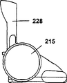
如图27至图31所示,吸尘器本体215,在内部由端部向长度方向平行地配设有集尘室216、集尘过滤器217及电动送风机218,形成大致圆筒状。As shown in FIGS. 27 to 31 , the
在吸尘器本体215的前方,设有吸引尘埃的吸气口219,尘埃由吸气口219吸引,被捕获在集尘室216的内部。另外,从集尘室216内部排出的排气,从电动送风机218的后方向外部空气排出或向吸气口219排出。电动机220通过皮带222而使设在吸气口219附近的刷体221旋转。In front of the
在吸尘器本体215的一端设有集尘室盖223,在另一端设有形成吸尘器本体215外壳的上部外壳224。A dust chamber cover 223 is provided at one end of the
在大致圆筒状的吸尘器本体215的外周225上,形成有以吸尘器本体215的大致中心为转动中心226而绕吸尘器本体215的外周225转动的大致圆筒状的手柄臂体227。手柄臂体227可使吸尘器本体215的吸气口219转动,以使吸气口219始终大致平行状与地面等接触。另外,手柄臂体227的外径设成与吸尘器本体215的外周225大致同等的直径,从手柄臂体227的外周配设棒状的突出部228,在突出部228的端部插入由管子等构成的多个延长管229,在该延长管229的顶端,形成有在操作吸尘器本体215时具有防滑性的把手230。A substantially cylindrical handle arm 227 that rotates around the outer periphery 225 of the
在上述结构中,大致圆筒状的手柄臂体227,因与大致圆筒状的吸尘器本体215的外周225同等的形状,故设计上可取消凹凸,可使其小型化。此外,转动的手柄臂体227的外径,由于是与吸尘器本体215的外周225同等直径的大小,故即使较大的冲击作用在手柄臂体227上也难以被破坏,可提高强度。In the above structure, the substantially cylindrical handle arm body 227 has the same shape as the outer periphery 225 of the substantially cylindrical vacuum
并且,在清扫时,在握持形成于手柄臂体227上的把手230而使吸尘器本体215往复时,可加大往复移动距离,使其往复的次数减少而可提高使用方便性。Moreover, when cleaning, when the
另外,如图29所示,使手柄臂体227位于大致在吸尘器本体215的长度方向大致中央,在手柄臂体227的内侧配设电动送风机218。采用这种结构,在握持手柄臂体227上的棒状突出部228等搬运时,由于手柄臂体227位于吸尘器本体215的大致中央,故吸尘器本体215的重量平衡良好,容易搬运。In addition, as shown in FIG. 29 , the handle arm body 227 is positioned substantially at the center in the longitudinal direction of the
此外,对于吸尘器本体215内的集尘室216、电动送风机218的配置无需多余的空间,可将吸尘器本体215的整体小型轻量化。In addition, no extra space is required for the arrangement of the dust collection chamber 216 and the electric blower 218 in the
另外,如图29及图30所示,将遮住电动送风机218外周的罩壳231外周设为支轴232,使手柄臂体227在支轴232上滑动。而罩壳231,将其一部分形成吸尘器本体215的外壳,由配设在罩壳231两端的集尘室盖223与上部外壳224卡止。采用这种结构,手柄臂体227的转动结构可由手柄臂体227与罩壳231的2个零件构成,不使用复杂的零件就可容易地形成。In addition, as shown in FIGS. 29 and 30 , the outer periphery of the
另外,如图27及图28所示,在手柄臂体227上的棒状的突出部228、由管子等构成的多个延长管229及具有防滑性的把手230的顶端,形成有外螺纹或内螺纹,分别成为装拆自如。采用这种结构,如图31所示,根据使用者的使用方便性较好的高度,来改变延长管229的使用根数,可调整把手230的把手高度,并可提高使用方便性。此外,通过将各延长管229及把手230卸下,还可收放成较小的收放空间。In addition, as shown in FIGS. 27 and 28 , on the rod-shaped protruding
另外,如图32所示,通过用螺钉等装拆自如地构成棒状的突出部228与具有防滑性的把手230,可使具有防滑性的把手230与突出部228连接,若握持把手230进行清扫,则可用作为轻便型的吸尘器,而且,因把手230具有防滑性,故无不适感,可进行操作。In addition, as shown in FIG. 32, the rod-shaped
另外,如图33所示,通过将棒状的突出部228用作为第2把手,可由扫帚式吸尘器可靠地作为轻便型的吸尘器来使用,可扩大清扫用途,提高使用方便性。In addition, as shown in FIG. 33, by using the rod-shaped protruding
下面,就本实用新型第9实施例结合图34及图35进行说明。Next, the ninth embodiment of the present utility model will be described with reference to Fig. 34 and Fig. 35 .
如图34所示,大致圆筒状的手柄臂体227,构成绕与大致圆筒状的吸尘器本体215外周225相同的轨迹转动,为使手柄臂体227向吸尘器本体215的前后方向作较大的转动,且可一直转动到棒状的突出部228与障碍物相碰为止,在吸尘器本体215的前后方向,将该手柄臂体227的转动设成使其相对地面约90°转动。其它结构与上述实施例8相同。As shown in Figure 34, the substantially cylindrical handle arm body 227 is formed to rotate around the same track as the outer periphery 225 of the substantially cylindrical vacuum
在上述结构中,如图34所示,当清扫狭窄的桌子下面等时,可有效利用延长管229的长度La,可一直清扫到深处为止。另外,从吸尘器本体215的前方、后方及任一侧也可根据使用者的使用方便性来清扫。In the above structure, as shown in FIG. 34, when cleaning under a narrow table, etc., the length La of the
如图35所示,吸尘器本体的转动方向,是以后方转动为主,故吸尘器本体的移动距离是使用者的手的长度与吸尘器本体的移动距离L1之和,但由于可使吸尘器本体215的转动也向前方方向较大地转动,故吸尘器本体215的移动可到距离L2为止,使吸尘器本体215一次往复的清扫地面面积增大,使吸尘器本体215往复的次数减少,可缩短时间。As shown in Figure 35, the rotation direction of the vacuum cleaner body is based on the rear rotation, so the moving distance of the vacuum cleaner body is the sum of the length of the user's hand and the moving distance L1 of the vacuum cleaner body. The rotation also rotates to the front direction greatly, so the movement of the
另外,如图36所示,在吸尘器本体215的下方后方形成凸部233,当向与地面垂直的方向倒放吸尘器本体215时,凸部233与吸尘器本体215的外周225与地面接触,通过维持作为后跟座(ヒ-ルレスト)233a的功能,可向垂直方向倒放吸尘器本体215而成为站立状态,在把吸尘器本体215收放在狭窄的场所时,通过向与地面垂直的方向倒放吸尘器本体215并使手柄臂体227向吸尘器本体215的前方方向转动,可缩短收放空间的进深尺寸L3,可提高收放性。In addition, as shown in FIG. 36 , a convex portion 233 is formed at the bottom and rear of the
下面,就本实用新型第10实施例结合图37至图40进行说明。Next, the tenth embodiment of the present utility model will be described with reference to Fig. 37 to Fig. 40 .
如图37及图38所示,在手柄臂体227的内侧,设置用加强筋234固定的板状弹簧235,如图39所示,该弹簧235的大致中央,向转动中心226突出成大致圆弧状236。As shown in Figure 37 and Figure 38, on the inner side of the handle arm body 227, a plate-shaped
与弹簧235的大致圆弧状236相对而配置多个在罩壳231上形成凹部237的凸起部238。弹簧235根据手柄臂体227转动的位置而嵌合、卡止在凹部237内。A plurality of protrusions 238 forming recesses 237 in the
使弹簧235的大致圆弧状236嵌合、卡止在凹部237内的弹簧力,在握持棒状的突出部228等而将吸尘器本体215浮在空中时,在将靠构成吸气口219的各零件的重量自然转动吸气口219的力设为(F)、并将握持把手230而使手柄臂体227向吸尘器本体215转动的力设为(F1)时,弹簧力设定成(F)≤(F1)。而使弹簧235的大致圆弧状236嵌合、卡止在各凹部237内的弹簧力设定成稍大于(F)。其它结构与上述实施例8相同。The spring force of the substantially arc-shaped 236 of the
在上述结构中,当握持把手230将吸尘器本体215浮在空中时,弹簧235对多个凹部237中任一个施力,抑制手柄臂体227的转动,当握持把手230来搬运吸尘器本体215时,手柄臂体227不会轻易转动,吸尘器本体215的卡止状态被维持,搬运中可无不适感地进行搬运。In the above structure, when holding the
另外,在欲设成清扫状态时,只要使手柄臂体227向吸尘器本体215的后方转动,吸气口219不会追随手柄臂体227地顺利地可进入清扫状态。In addition, when the cleaning state is to be set, as long as the handle arm body 227 is rotated to the rear of the
如图37及图39所示,手柄臂体227上的棒状的突出部228是相对地面大致垂直的位置,在吸尘器本体215的大致中心线上239,配置弹簧235的大致圆弧状236,并配置在罩壳231上多个设置中的1个凹部237。在形成凹部237的凸起部238的两端形成有突出余量240。当将突出余量240的吸尘器本体215的前方侧设为第1突出余量,相反地,将吸尘器本体215的后方侧设为第2突出余量242时,前方侧的第1突出余量241与后方侧的第2突出余量242相比,稍向外侧突出一点。As shown in FIGS. 37 and 39 , the rod-shaped protruding
采用这种结构,当使手柄臂体227转动时,与手柄臂体227联动的弹簧235的大致圆弧状236搁置在突出余量240上。这里,前方侧的第1突出余量241由于与后方侧的第2突出余量242相比,稍向外侧突出一点,且由于弹簧235的大致圆弧状236搁置在突出余量240上的力较大,故如图41所示,用把手230使手柄臂体227向吸尘器本体215的后方转动的力(F2)就比向前方转动的力(F3)小。With this structure, when the handle arm body 227 is rotated, the substantially circular arc shape 236 of the
因此,在将延长管229及把手230相对地面置于垂直状态的通常的吸尘器本体215的收放时或保管时,站立状态下的放置性提高,延长管229及把手230不会轻易地倾倒。Therefore, when the
另外,在实际进行清扫时,握持把手230而使手柄臂体227转动的动作,由于往往向吸尘器本体215的后方转动,因此,手柄臂体227的转动力即使相对地面在垂直状态的位置产生变化,操作上,也较少使把手230相对地面设成垂直状态来操作,故操作上无问题,可使用。In addition, when actually cleaning, the action of holding the
下面,就本实用新型第11实施例结合图42进行说明。Next, the eleventh embodiment of the present utility model will be described with reference to FIG. 42 .
如图42所示,限位开关243是对电动送风机218的通电电路进行接通、断开用的,利用凸条244固定在罩壳231上。另外,在手柄臂体227的内侧,形成有在手柄臂体227转动时对限位开关243的接点部245进行按压的接点条246。其它结构与上述实施例8相同。As shown in FIG. 42 , the limit switch 243 is used to switch on and off the electric circuit of the electric blower 218 , and is fixed on the
在上述结构中,通过使手柄臂体227转动,接点条246使限位开关243的接点部245动作,因使手柄臂体227转动,故不对作起动及停止的开关进行操作,就可马上处于清扫状态,可提高使用方便性。In the above structure, by turning the handle arm body 227, the contact bar 246 moves the contact point 245 of the limit switch 243. Because the handle arm body 227 is rotated, the switch for starting and stopping is not operated, and the position can be immediately set. The cleaning state can improve the convenience of use.
下面,就本实用新型第12实施例结合图43至图46进行说明。Next, the twelfth embodiment of the present utility model will be described with reference to Fig. 43 to Fig. 46 .
如图所示,在吸尘器本体301的上部倾动自如地设置有操作用的手柄302。在吸尘器本体301的内部装有二次电池303和由它驱动的电动送风机304。即,在吸尘器本体301的后方配设电动送风机304,在该电动送风机304的吸引侧形成集尘部301b。另外,在吸尘器本体301的前方设置吸入尘埃用的吸入部301a,该吸入部301a与集尘部301b通过通道而连接。在吸入部301a的上部配设二次电池303。As shown in the figure, a
此外,在吸尘器本体301的后方下面,设置充电用的端子连接部305和孔部306。端子连接部305配置在离开吸尘器本体301中心部的电动送风机304后部的电动机304a外周部的空间中。端子连接部305呈从下面进入电动送风机304、电动机304a外周侧空间内的凹部形状,在该凹部的内壁上安装端子305a。在吸尘器本体301的后端部,以从吸尘器本体301的下面及后面突出的状态设置行走用的后部滚轮316。Moreover, the
充电器307用箱状部308与充电用的端子部309构成,充电用的端子部309设在箱状部308的前部,并被插入吸尘器本体301的端子连接部305的凹部内。在箱状部308内的端子部309附近放置充电用的电源变压器310。The
另外,在箱状部308的前面下面形成向前方延伸的板状部(相当于放置部)311,再在该板状部311设置插入吸尘器本体301孔部306内的凸部312。在吸尘器本体301的端子连接部305内插入充电器307的端子部309,在将端子之间连接的状态下,在吸尘器本体301的孔部306内嵌合板状部311的凸部312,通过端子连接部305与端子部309的连接,及孔部306与凸部312的嵌合,吸尘器本体301就被限制在充电器307所决定的位置上。In addition, a plate-shaped portion (corresponding to a placement portion) 311 extending forward is formed on the lower front surface of the box-shaped
从箱状部308的两侧面向前方延设导向体313,该导向体313在将吸尘器本体301载放在充电器307上的情况下,将端子连接部305与端子部309及孔部306与凸部312导向成分别对应,导向体313的间隔A与吸尘器本体301的载放在充电器307上的部分宽度B之间的关系是A≥B。最好将A设定成比B稍大。
箱状部308的前面上部形成倾斜面314,吸尘器本体301的后部滚轮316在该倾斜面314上滚动。在箱状部308的上面设有通电显示用的显示灯315。The upper front part of the box-shaped
在上述结构中,由于将二次电池303与电动送风机304容纳在内部,由具有充电用的端子连接部305的吸尘器本体301和与吸尘器本体301分开设置的充电器307所构成,且该充电器307包括放置电源变压器310的箱状部308和比该箱状部308还向前方突出的充电用的端子部309,故可将充电器307本身的大小小型化。尤其由于充电器307将吸尘器本体301的后方侧载放在板状部311上,位于吸尘器本体301前方的吸入部301a位于比板状部311还前方的位置,故与也载放吸入部的传统充电器相比其大小显著地减小。In the above structure, since the
另外,从充电器307的箱状部308侧壁使充电用的端子部309突出,因将充电用的端子部309插入设在吸尘器本体301的吸入部301a以外部位的充电用的端子连接部305内,故可缩小在将吸尘器本体301置于充电器307上的状态下的整体外形尺寸,在充电时或收放时可不占用放置场所。In addition, the
在吸入部301a内设置了旋转刷子的架构中,附着在旋转刷子上的尘埃在将吸尘器本体301置于充电器307上时会落在地面上,但如上所述,由于所述尘埃不落在充电器307上,因此,欲开始清扫,只要从充电器307上卸下吸尘器本体301,就可简单地吸取落在地面上的尘埃。In the structure in which the rotating brush is provided in the
另外,从充电器307的箱状部308前面的底面附近设置载放吸尘器本体301一部分的板状部311,并且在板状部311上和与其相对的吸尘器本体301的下面,分别设置至少一对以上的互相卡合的凸部312及孔部306,这样,能可靠地将吸尘器本体301固定在充电器307上。In addition, a plate-shaped
另外,从充电器307的箱状部308前面的两端面附近设置一对导向体313,由于吸尘器本体301的后方部被限位在它们之间,故能更容易而可靠地将吸尘器本体301置于充电器307上。尤其,在握持手柄302上端侧的握持部将吸尘器本体301置于充电器307上的情况下,因导向体313的作用而能顺利且可靠地进行,并能提高充电器307整体的强度。In addition, a pair of
另外,由于将充电器307的箱状部308前面上部设成倾斜面314,故后部滚轮316可在该倾斜面314上滚动,可更顺利地将吸尘器本体301置于充电器307上。在本实施例中,是将充电器307的与吸尘器本体301相对的面设成由平面构成的倾斜面,但若是半径较大的圆筒面(可以是凹面、凸面的任何一种)等成为引导形状的其它类似形状也可获得同等的效果。另外,若将吸尘器本体301侧的与充电器307相对的面设成倾斜面或圆筒面也可获得同样的效果,不言而喻,再通过对双方进行实施可进一步提高这种效果。In addition, since the front upper part of the box-shaped
另外,在电动送风机304的电动机304a的外周部设置充电用的端子连接部305,即,不向吸尘器本体301外突出地设置端子连接部305,这样,可将吸尘器本体301的大小小型化,包含充电器307的充电状态的整体尺寸也可小型化。由于使电气零件接近,故可获得内部接线的集中化、合理化。In addition, the
在离开充电器307的箱状部308宽度方向的中心线上的位置具有充电用的端子部309的充电器307中,因将电源变压器310配置在充电用的端子部309附近,故在将吸尘器本体301从充电器307上卸下时,由于充电器307上产生的外力与充电器307上产生的重力作用在接近的点上,故可顺利地把吸尘器本体301从充电器307上取下。In the
在将吸尘器本体301置于充电器307上时,因在与手柄302相对的箱状部308的上面设置显示灯315,故将吸尘器本体301置于充电器307上时的目标容易找到,可容易地操作。When the
此外,由于在吸尘器本体301的后端部以从吸尘器本体301的下面及后面突出的状态设置行走用的后部滚轮316,故在将吸尘器本体301置于充电器307上时,即使在充电器307的倾斜面314或箱状部308的前面干扰吸尘器本体301后部的情况下,然而因后部滚轮316抵接在倾斜面314或箱状部308上,故阻力变小,可容易地进行装拆作业,并且,通过将软质材料用于滚轮,还可期待减轻在装拆时所产生的冲击的效果和防止损坏的效果。In addition, since the rear end portion of the
下面,就本实用新型第13实施例结合图47至图53进行说明。Next, the thirteenth embodiment of the present utility model will be described with reference to Fig. 47 to Fig. 53 .
如图所示,在吸尘器本体401的上部,转动自如地保持具有约1m长的操作用的手柄402。在吸尘器本体401的内部,设置二次电池403和由该二次电池403驱动的电动送风机404。此外,在吸尘器本体401的后方下面设有充电用的端子连接部405和孔部406。在吸尘器本体401的内部内藏有开关417,随着与手柄402结合的环状体402a以吸尘器本体401的圆筒轴部401c作为轴向后方转动,在环状体402a的一部分上设置的凸轮面402b就按压开关417的杆417a,开关417接通。即,以凸轮面402b的倾斜部为界切换断开状态与接通状态。处于断开状态的手柄402从直立的状态到切换成接通状态的手柄402的倒下角度是约10度,对此,在实际使用状态下的倒下角度,在手柄长度为1m时至少处于30度左右,在使用中开关417不会被断开。As shown in the figure, an
充电器407由箱状部408与在其前部设置的充电用的端子部409构成。在箱状部408内的端子部409附近设置充电用的电源变压器410。在充电器407的外观面上设有通电显示用的显示灯415。The
在箱状部408的前面下端形成板状部411,再在该板状部411上设置凸部(被卡合部)412,在将吸尘器本体401的端子连接部405与充电器407的端子部409连接的状态下,该凸部412设在嵌入孔部406内的位置。在端子连接部405上设置正极连接端子405a和负极连接端子405b,在端子部409上设置正极充电端子409a和负极充电端子409b,正极、负极的各端子设成仅互相接触的简单结构。A plate-
此外,在手柄402处于开关417被断开的位置时,由于在成为与孔部406相同位置的环状体402a的外周面上设有凹部(卡合部)402c,故当将吸尘器本体401置于充电器407上时,在凸部412贯通孔部406后就嵌入凹部402c。另外,在凸部412的顶端设有倾斜部412a,并在充电器407的顶面上设有用发光二极管的显示灯415。In addition, when the
在上述结构中,在手柄402处于开关417被断开的位置时,一旦将吸尘器本体401置于充电器407上,则由于凸部412在贯通孔部406后嵌入凹部402c内,故在放置后的状态下手柄402不转动,从而开关417不会被断开。相反,在开关417接通后的状态下,手柄402就转动,从而凹部402c移动到与孔部406不同的位置上,不会将吸尘器本体401正常状态地置于充电器407上。因此,正极连接端子405a与正极充电端子409a、负极连接端子405b与负极充电端子409b,在开关417接通后的状态下都不互相接触,仅在开关被断开后的状态下接触,且充电器407侧与吸尘器本体401侧的电路被连接。In the above structure, when the
凹部402c与孔部406设在吸尘器本体401的底面上,相对的凸部412从充电器407向上方突出,只要位置对准后,就可利用吸尘器本体401的自重而自动嵌合。The concave part 402c and the hole part 406 are provided on the bottom surface of the
另外,由于孔部406设在吸尘器本体401的非可动零件上,故能可靠地将吸尘器本体401定位在充电器407上。由于在凸部412的顶端部的外周上设有倾斜部412a,因此,即使吸尘器本体401的底面的孔部406与凹部402c多多少少产生偏差,倾斜部412a也可一边引导凹部402c的入口,一边使凹部402c移动到正常的位置上。设在充电器407外观面上的显示灯415,仅在吸尘器本体401被正常状态地放置在充电器407上、端子连接部405与端子部409接触时点亮。In addition, since the hole 406 is provided on the non-movable part of the
如此,通过设置与设在充电器407上的凸部(被卡合部)412卡合而将吸尘器本体401置于充电器407上的凹部(卡合部)402c,该凹部402c设成根据手柄402的操作而移动、在开关417的接通状态的位置,凹部402c不与凸部412卡合的结构,从而在机构上仅在开关417被断开时,就可将吸尘器本体401与充电器407连接,电路结构变得简单,使接线所产生的产品不合格率下降,其结果,可价廉而更可靠地进行充电,可提高使用方便性。In this way, the
另外,由于将手柄402设为开关417的操作部,故不必增加另外部件,能可靠地仅在开关417被断开时将吸尘器本体401与充电器407连接,既价廉又可提高使用方便性。In addition, since the
此外,由于使凹部(卡合部)402c面对吸尘器本体401的底面,吸尘器本体401与充电器407的嵌合动作就靠吸尘器本体401的自重来进行,故一旦嵌合,除非人为提起吸尘器本体401或施加相当大的冲击,吸尘器本体401不会脱离充电器407,能进行更可靠的充电。In addition, since the concave portion (engagement portion) 402c faces the bottom surface of the
并且,由于通过设在吸尘器本体401底面上的孔部406而使设在充电器407上的凸部(被卡合部)412与凹部402c卡合,且由于吸尘器本体401相对于充电器407的定位不受手柄402的转动松动等影响,故位置偏差不仅难以产生,而且凸部412被可靠地导向到正常的位置,从而可更正确地使端子连接部405与端子部409接触,能进行更可靠的充电。Moreover, since the convex portion (engaged portion) 412 provided on the
此外,由于在设置于充电器407上的凸部412的顶端设有倾斜部412a,故即使在吸尘器本体401的底面的孔部406与凹部402c多多少少产生偏差的情况下,倾斜部412a也可一边引导凹部402c的入口,一边使凹部402c移动到正常的位置上,故吸尘器本体401相对充电器407不会发生安装不充分的情况,能进行更可靠的充电。In addition, since the top end of the
又,由于在充电器407内部或吸尘器本体401内部的任何一方,设有仅在吸尘器本体401与充电器407电气连接时产生动作的显示灯415,故可减少因吸尘器本体401不完全放置在充电器407上所产生的误充电现象。Again, since any one of the interior of the
在本实施例中,是将显示灯415用作为报知装置的,但不限定于视觉上的结构,不言而喻,也可使用电子报警器等听觉上的结构等所有装置。In the present embodiment, the
Claims (44)
Applications Claiming Priority (10)
| Application Number | Priority Date | Filing Date | Title |
|---|---|---|---|
| JP19006298 | 1998-07-06 | ||
| JP190062/98 | 1998-07-06 | ||
| JP19119498 | 1998-07-07 | ||
| JP191194/98 | 1998-07-07 | ||
| JP191195/98 | 1998-07-07 | ||
| JP19119598 | 1998-07-07 | ||
| JP302461/98 | 1998-10-23 | ||
| JP30246198 | 1998-10-23 | ||
| JP302462/98 | 1998-10-23 | ||
| JP30246298 | 1998-10-23 |
Publications (1)
| Publication Number | Publication Date |
|---|---|
| CN2380174Y true CN2380174Y (en) | 2000-05-31 |
Family
ID=27528998
Family Applications (3)
| Application Number | Title | Priority Date | Filing Date |
|---|---|---|---|
| CNB2004100978256A Expired - Fee Related CN1305434C (en) | 1998-07-06 | 1999-07-06 | Vacuum cleaner |
| CN99215585U Expired - Lifetime CN2380174Y (en) | 1998-07-06 | 1999-07-06 | Dust collector |
| CNB991103149A Expired - Fee Related CN1181782C (en) | 1998-07-06 | 1999-07-06 | Vacuum cleaner |
Family Applications Before (1)
| Application Number | Title | Priority Date | Filing Date |
|---|---|---|---|
| CNB2004100978256A Expired - Fee Related CN1305434C (en) | 1998-07-06 | 1999-07-06 | Vacuum cleaner |
Family Applications After (1)
| Application Number | Title | Priority Date | Filing Date |
|---|---|---|---|
| CNB991103149A Expired - Fee Related CN1181782C (en) | 1998-07-06 | 1999-07-06 | Vacuum cleaner |
Country Status (10)
| Country | Link |
|---|---|
| US (3) | US6345411B1 (en) |
| EP (3) | EP1522249B1 (en) |
| KR (4) | KR200163307Y1 (en) |
| CN (3) | CN1305434C (en) |
| CA (1) | CA2276796C (en) |
| DE (3) | DE69931830T2 (en) |
| ES (3) | ES2271769T3 (en) |
| HK (1) | HK1025023A1 (en) |
| MY (1) | MY126748A (en) |
| TW (1) | TW412412B (en) |
Cited By (3)
| Publication number | Priority date | Publication date | Assignee | Title |
|---|---|---|---|---|
| CN1305434C (en) * | 1998-07-06 | 2007-03-21 | 松下电器产业株式会社 | Vacuum cleaner |
| CN106691319A (en) * | 2017-03-17 | 2017-05-24 | 朱龙 | All-in-one machine with sweeping, vacuuming and mopping functions |
| CN109157153A (en) * | 2016-08-30 | 2019-01-08 | 王晶晶 | A kind of domestic dedusting bell-type device |
Families Citing this family (104)
| Publication number | Priority date | Publication date | Assignee | Title |
|---|---|---|---|---|
| EP1010388B1 (en) * | 1998-12-17 | 2010-01-06 | AEG Hausgeräte GmbH | Floor cleaning apparatus |
| JP2001037687A (en) * | 1999-08-02 | 2001-02-13 | Matsushita Electric Ind Co Ltd | Vacuum cleaner |
| JP2001169980A (en) * | 1999-12-15 | 2001-06-26 | Sanyo Electric Co Ltd | Vacuum cleaner |
| CN1143651C (en) * | 2000-03-01 | 2004-03-31 | 松下电器产业株式会社 | electric vacuum cleaner |
| CN1240336C (en) * | 2000-05-17 | 2006-02-08 | 松下电器产业株式会社 | Electric dust collector |
| JP2001353113A (en) * | 2000-06-15 | 2001-12-25 | Sanyo Electric Co Ltd | Electric vacuum cleaner |
| JP2002000527A (en) * | 2000-06-23 | 2002-01-08 | Sanyo Electric Co Ltd | Vacuum cleaner |
| US7571511B2 (en) * | 2002-01-03 | 2009-08-11 | Irobot Corporation | Autonomous floor-cleaning robot |
| US6883201B2 (en) | 2002-01-03 | 2005-04-26 | Irobot Corporation | Autonomous floor-cleaning robot |
| US6581241B2 (en) * | 2001-06-21 | 2003-06-24 | Black & Decker Inc. | Vacuum cleaner having airflow recirculation path for cooling beater brush motor |
| GB2377163B (en) * | 2001-07-05 | 2004-12-15 | Hoover Ltd | Vacuum cleaner |
| US7013528B2 (en) * | 2002-01-28 | 2006-03-21 | Bissell Homecare, Inc. | Floor cleaner with dusting |
| WO2004010839A1 (en) * | 2002-07-25 | 2004-02-05 | Toshiba Tec Kabushiki Kaisha | Vacuum cleaner |
| GB2391459A (en) * | 2002-08-09 | 2004-02-11 | Dyson Ltd | A surface treating appliance with increased manoeuverability |
| WO2004041054A1 (en) * | 2002-11-06 | 2004-05-21 | Polar Light Limited | Battery-powered vacuum cleaner |
| FR2852811B1 (en) * | 2003-03-27 | 2005-06-24 | Nielsen Innovation | AUTONOMOUS BIMOTING VACUUM CLEANER |
| JP3905867B2 (en) * | 2003-07-17 | 2007-04-18 | 東芝テック株式会社 | Rechargeable vacuum cleaner |
| US7712182B2 (en) * | 2003-07-25 | 2010-05-11 | Milwaukee Electric Tool Corporation | Air flow-producing device, such as a vacuum cleaner or a blower |
| DE10336827A1 (en) * | 2003-08-11 | 2005-03-10 | Bsh Bosch Siemens Hausgeraete | Vacuum cleaner with a blower capsule |
| CN1582838A (en) * | 2003-08-21 | 2005-02-23 | 张周新 | Air circulating device of dust cleaner |
| ITPD20040008A1 (en) * | 2004-01-20 | 2004-04-20 | Lindhaus Srl | PERFECTED STRUCTURE OF CARPET, FLOOR WASHER, SWEEPER, LU CIDATRICE AND SIMILAR TO TWO MOTORS |
| GB2410178B (en) * | 2004-01-20 | 2007-05-23 | Lindhaus S R L | Cleaning device |
| AU2005218490B2 (en) * | 2004-03-02 | 2010-04-01 | Bissell Inc. | Vacuum cleaner with detachable cyclonic vacuum module |
| WO2006015309A2 (en) | 2004-07-29 | 2006-02-09 | Electrolux Care Products, Ltd | Upright vacuum cleaner |
| US20060026788A1 (en) * | 2004-08-06 | 2006-02-09 | Fischer Richard J | Upright vacuum cleaner incorporating telescopic handle and wand assembly with electrified hose |
| US7958652B2 (en) * | 2005-01-07 | 2011-06-14 | Bissell Homecare Inc. | Extraction cleaning with plenum and air outlets facilitating air flow drying |
| US7793385B2 (en) * | 2005-01-07 | 2010-09-14 | Bissell Homecare Inc. | Extraction cleaning with air flow drying |
| JP2008526449A (en) * | 2005-01-18 | 2008-07-24 | エレクトラックス ホーム ケア プロダクツ,リミテッド | Vacuum cleaner with folding handle |
| US7631387B2 (en) * | 2005-05-13 | 2009-12-15 | Black & Decker Inc. | Motorized broom and collector |
| EP1752076B1 (en) * | 2005-08-11 | 2009-10-21 | BLACK & DECKER INC. | Hand-holdable vacuum cleaners |
| USD544158S1 (en) * | 2006-01-18 | 2007-06-05 | Electrolux Home Care Products, Ltd. | Vacuum cleaner base |
| EP1815777A1 (en) * | 2006-02-01 | 2007-08-08 | Team International Marketing SA/NV | Suction cleaning unit comprising a floor vacuum cleaner and a hand-held vacuum cleaner |
| ATE517570T1 (en) * | 2006-10-20 | 2011-08-15 | Wessel Werk Gmbh | COMPACT VACUUM CLEANING DEVICE FOR AUTHORIZED CLEANING OF FLOOR COVERINGS |
| EP2223644B1 (en) * | 2007-02-12 | 2014-03-26 | Black & Decker Inc. | Motor, fan and filter arrangement for a vacuum cleaner |
| KR101340423B1 (en) * | 2007-08-28 | 2013-12-13 | 삼성전자주식회사 | A Stick Type Vacuum Cleaner |
| DE102008008069A1 (en) * | 2008-02-01 | 2009-08-06 | Alfred Kärcher Gmbh & Co. Kg | Floor cleaning device |
| US8316506B1 (en) * | 2008-05-28 | 2012-11-27 | Spalj Thomas J | Surface debris removal apparatus |
| JP2010125009A (en) * | 2008-11-26 | 2010-06-10 | Toshiba Corp | Electric cleaner |
| US8001653B1 (en) * | 2009-06-04 | 2011-08-23 | Longley Everton W | Vacuum apparatus |
| GB2474465B (en) * | 2009-10-15 | 2013-10-23 | Dyson Technology Ltd | A surface treating appliance |
| GB2474470B (en) | 2009-10-15 | 2013-10-23 | Dyson Technology Ltd | A surface treating appliance |
| GB2474469B (en) * | 2009-10-15 | 2013-11-13 | Dyson Technology Ltd | A surface treating appliance |
| GB2474466B (en) * | 2009-10-15 | 2014-03-05 | Dyson Technology Ltd | A surface treating appliance |
| GB2474471B (en) * | 2009-10-15 | 2013-10-23 | Dyson Technology Ltd | A surface treating appliance |
| GB2474462B (en) | 2009-10-15 | 2013-12-11 | Dyson Technology Ltd | A surface treating appliance with domed-shaped wheels |
| GB0918027D0 (en) * | 2009-10-15 | 2009-12-02 | Dyson Technology Ltd | A surface trating appliance |
| GB2474473B (en) * | 2009-10-15 | 2013-10-23 | Dyson Technology Ltd | A surface treating appliance |
| GB2474472B (en) * | 2009-10-15 | 2013-10-23 | Dyson Technology Ltd | A surface treating appliance |
| GB2474468B (en) | 2009-10-15 | 2013-11-27 | Dyson Technology Ltd | A surface treating appliance |
| GB2474464B (en) * | 2009-10-15 | 2013-11-20 | Dyson Technology Ltd | A surface treating appliance |
| GB2474475B (en) * | 2009-10-15 | 2013-10-23 | Dyson Technology Ltd | A surface treating appliance |
| GB2474463B (en) * | 2009-10-15 | 2013-11-13 | Dyson Technology Ltd | A surface treating appliance |
| FR2963169B1 (en) * | 2010-07-21 | 2013-05-17 | Ingenico Sa | HOST BASE FOR A MOBILE TERMINAL AND CORRESPONDING MOBILE TERMINAL |
| WO2012028169A1 (en) * | 2010-08-30 | 2012-03-08 | Lothar Munder | Device and method for cleaning a surface |
| US8769767B2 (en) | 2011-03-03 | 2014-07-08 | G.B.D. Corp. | Removable cyclone chamber and dirt collection assembly for a surface cleaning apparatus |
| US8869345B2 (en) | 2011-03-03 | 2014-10-28 | G.B.D. Corp. | Canister vacuum cleaner |
| US8973212B2 (en) | 2011-03-03 | 2015-03-10 | G.B.D. Corp. | Filter housing construction for a surface cleaning apparatus |
| US9101252B2 (en) | 2011-03-03 | 2015-08-11 | G.B.D. Corp. | Configuration of a surface cleaning apparatus |
| US8739359B2 (en) | 2011-03-03 | 2014-06-03 | G.B.D. Corp. | Configuration of a surface cleaning apparatus |
| US8739357B2 (en) | 2011-03-03 | 2014-06-03 | G.B.D. Corp | Filter construction for a surface cleaning apparatus |
| US8646149B2 (en) * | 2011-03-03 | 2014-02-11 | G.B.D. Corp. | Filter housing construction for a surface cleaning apparatus |
| US8763202B2 (en) | 2011-03-03 | 2014-07-01 | G.B.D. Corp. | Cyclone chamber and dirt collection assembly for a surface cleaning apparatus |
| US8528160B2 (en) * | 2011-03-03 | 2013-09-10 | G.B.D. Corp. | Suction motor and fan assembly housing construction for a surface cleaning apparatus |
| US8813306B2 (en) | 2011-03-03 | 2014-08-26 | G.B.D. Corp. | Openable side compartments for a surface cleaning apparatus |
| US8973214B2 (en) | 2011-03-03 | 2015-03-10 | G.B.D. Corp. | Cyclone chamber and dirt collection assembly for a surface cleaning apparatus |
| US8978198B2 (en) | 2011-03-03 | 2015-03-17 | G.B.D. Corp. | Filter housing for a surface cleaning apparatus |
| EP2581011B1 (en) * | 2011-10-12 | 2015-07-15 | Black & Decker Inc. | A hand-holdable vacuum cleaner |
| EP2581010B1 (en) * | 2011-10-12 | 2016-03-16 | Black & Decker Inc. | A battery - powered vacuum cleaner |
| EP2581014A1 (en) * | 2011-10-12 | 2013-04-17 | Black & Decker Inc. | A vaccum cleaner |
| GB2512025B (en) * | 2013-01-11 | 2017-03-01 | Techtronic Floor Care Tech Ltd | Surface treatment device |
| CN103284659A (en) * | 2013-06-21 | 2013-09-11 | 苏州金威特工具有限公司 | Dust collector handle with adjustable heights |
| US9307881B2 (en) | 2014-03-12 | 2016-04-12 | Techtronic Industries Co. Ltd. | Extractor cleaning machine |
| KR101615430B1 (en) | 2014-05-09 | 2016-04-25 | 엘지전자 주식회사 | Vacuum cleaner |
| DE102014113796B4 (en) * | 2014-09-24 | 2020-04-23 | Vorwerk & Co. Interholding Gmbh | vacuum cleaner |
| US9668630B2 (en) | 2014-12-17 | 2017-06-06 | Omachron Intellectual Property Inc. | All in the head surface cleaning apparatus |
| US9883781B2 (en) | 2014-12-17 | 2018-02-06 | Omachron Intellectual Property Inc. | All in the head surface cleaning apparatus |
| US11202544B2 (en) | 2014-12-17 | 2021-12-21 | Omachron Intellectual Property Inc. | All in the head surface cleaning apparatus |
| US9775481B2 (en) | 2014-12-17 | 2017-10-03 | Omachron Intellectual Property Inc. | All in the head surface cleaning apparatus |
| US10357136B2 (en) | 2014-12-17 | 2019-07-23 | Omachron Intellectual Property Inc. | All in the head surface cleaning apparatus |
| US9775480B2 (en) | 2014-12-17 | 2017-10-03 | Omachron Intellectual Property Inc. | All in the head surface cleaning apparatus |
| US9668624B2 (en) | 2014-12-17 | 2017-06-06 | Omachron Intellectual Property Inc. | All in the head surface cleaning apparatus |
| US9545180B2 (en) | 2014-12-17 | 2017-01-17 | Omachron Intellectual Property Inc. | All in the head surface cleaning apparatus |
| US9295363B1 (en) * | 2014-12-17 | 2016-03-29 | Omachron Intellectual Property Inc. | All in the head surface cleaning apparatus |
| US9901229B2 (en) | 2014-12-17 | 2018-02-27 | Omachron Intellectual Property Inc. | All in the head surface cleaning apparatus |
| US9775479B2 (en) | 2014-12-17 | 2017-10-03 | Omachron Intellectual Property Inc. | All in the head surface cleaning apparatus |
| US9795264B2 (en) | 2014-12-17 | 2017-10-24 | Omachron Intellectual Property Inc. | All in the head surface cleaning apparatus |
| US9717383B2 (en) | 2014-12-17 | 2017-08-01 | Omachron Intellectual Property Inc. | All in the head surface cleaning apparatus |
| US10022027B2 (en) | 2014-12-17 | 2018-07-17 | Omachron Intellectual Property Inc. | All in the head surface cleaning apparatus |
| JP6435204B2 (en) * | 2015-01-28 | 2018-12-05 | 日立アプライアンス株式会社 | Electric vacuum cleaner |
| US10966584B2 (en) | 2015-08-06 | 2021-04-06 | Sharkninja Operating Llc | Low profile surface cleaning head |
| CN105747994B (en) * | 2016-03-07 | 2018-11-27 | 江苏美的清洁电器股份有限公司 | Dust catcher |
| CN105775473B (en) * | 2016-04-25 | 2019-01-15 | 向桂南 | Dust collection garbage can for sweeping floor |
| GB2550179B (en) * | 2016-05-11 | 2018-05-02 | Lupe Tech Limited | Cleaner head |
| WO2018085356A1 (en) * | 2016-11-01 | 2018-05-11 | Sharkninja Operating Llc | Multi-mode cleaning apparatus with suction |
| GB2585358B (en) * | 2016-11-01 | 2021-12-22 | Sharkninja Operating Llc | Multi-mode cleaning apparatus with suction |
| KR102519650B1 (en) | 2017-03-03 | 2023-04-10 | 엘지전자 주식회사 | Supporting device for cleaner and cleaner unit |
| CN106963285A (en) * | 2017-04-28 | 2017-07-21 | 苏州市海朋电子商务有限公司 | Cleaner suction nozzle |
| US11980334B2 (en) | 2017-09-15 | 2024-05-14 | Omachron Intellectual Property Inc. | Surface cleaning apparatus |
| KR20200073966A (en) | 2018-12-14 | 2020-06-24 | 삼성전자주식회사 | Cleaning device having vacuum cleaner and docking station |
| CN110051272A (en) * | 2018-12-26 | 2019-07-26 | 杰之深(苏州)科技有限公司 | A kind of multifunctional dust vacuum cleaner ground brush configuration and dust catcher |
| CN111449253B (en) * | 2020-06-05 | 2022-08-30 | 义乌市巨界机械设备有限公司 | Device for cleaning outer surface of durian after durian picking |
| JP7030349B2 (en) * | 2020-06-16 | 2022-03-07 | アイリスオーヤマ株式会社 | Vacuum cleaner extension pipe and vacuum cleaner unit |
| WO2022026728A1 (en) | 2020-07-29 | 2022-02-03 | Sharkninja Operating Llc | Nozzle for a surface treatment apparatus and a surface treatment apparatus having the same |
| CN118253142B (en) * | 2024-05-11 | 2024-08-20 | 湖北中材环保设备有限公司 | Box-type bag-type dust collector convenient to assemble |
Family Cites Families (44)
| Publication number | Priority date | Publication date | Assignee | Title |
|---|---|---|---|---|
| US1965614A (en) * | 1931-04-27 | 1934-07-10 | Hoover Co | Suction cleaner |
| GB740526A (en) * | 1953-12-28 | 1955-11-16 | Regina Corp | Improvements in or relating to machines for cleaning floors or carpets |
| US3704482A (en) * | 1970-10-08 | 1972-12-05 | Joseph W Brannon | Cleaning device |
| US4173809A (en) * | 1978-06-30 | 1979-11-13 | Ku Paul H | Automatic vacuum cleaner |
| US4393536A (en) * | 1982-01-25 | 1983-07-19 | Tapp Ruel W | Dual mode vacuum cleaner |
| JPS59230519A (en) * | 1983-06-13 | 1984-12-25 | 三洋電機株式会社 | Portable electric cleaner |
| DE3475161D1 (en) * | 1983-10-19 | 1988-12-22 | Matsushita Electric Ind Co Ltd | Vacuum cleaner |
| US4536694A (en) * | 1984-02-21 | 1985-08-20 | Solid State Chargers Research And Development | Battery-operated device with wall-mounted support |
| US4670701A (en) * | 1984-11-19 | 1987-06-02 | Matsushita Electric Industrial Co., Ltd. | Rechargeable cordless vacuum cleaner apparatus |
| US4665582A (en) * | 1985-02-22 | 1987-05-19 | National Union Electric Corp. | Lightweight battery powered suction broom |
| DE8513126U1 (en) * | 1985-05-04 | 1985-08-01 | Fasse, geb. Brink, Käthe, 2950 Leer | Circulating air vacuum cleaner |
| US5005252A (en) * | 1987-07-24 | 1991-04-09 | Emerson Electric Co. | Portable wet/dry vacuum cleaner and recharging base |
| US4835409A (en) * | 1988-02-26 | 1989-05-30 | Black & Decker Inc. | Corded/cordless dual-mode power-operated device |
| US5025529A (en) * | 1988-08-08 | 1991-06-25 | Emerson Electric Co. | Portable hand held vacuum cleaner |
| US5014388A (en) * | 1989-05-15 | 1991-05-14 | White Consolidated Industries, Inc. | Battery powered vacuum cleaner |
| EP0413415A1 (en) | 1989-06-13 | 1991-02-20 | The British Petroleum Company p.l.c. | Carboxylic acids and derivates thereof |
| JPH0357254Y2 (en) * | 1989-11-02 | 1991-12-26 | ||
| DE69006827T2 (en) * | 1989-12-01 | 1994-06-01 | William Hendrick Williams | Wet-dry vacuum cleaner. |
| JPH03272720A (en) * | 1990-03-23 | 1991-12-04 | Mitsubishi Electric Corp | Vacuum cleaner |
| US5109566A (en) * | 1990-06-28 | 1992-05-05 | Matsushita Electric Industrial Co., Ltd. | Self-running cleaning apparatus |
| JPH04164422A (en) * | 1990-10-30 | 1992-06-10 | Azuma Kogyo Kk | Vacuum cleaner |
| JPH05111167A (en) * | 1991-10-17 | 1993-04-30 | Hitachi Ltd | Rechargeable cleaner |
| JP3048784B2 (en) * | 1993-05-14 | 2000-06-05 | 三洋電機株式会社 | Chargers and electronic devices |
| CA2123740C (en) * | 1993-05-19 | 2002-12-17 | Hee-Gwon Chae | Electric vacuum cleaner |
| US5323510A (en) * | 1993-07-09 | 1994-06-28 | Redding Glenn K | Vacuum cleaner having improved steering features |
| US5520872A (en) * | 1993-08-09 | 1996-05-28 | Scherer; Philip G. | Method for hemming edges of stretch film |
| TW267098B (en) * | 1994-02-16 | 1996-01-01 | Matsushita Electric Ind Co Ltd | |
| US5553347A (en) * | 1994-04-19 | 1996-09-10 | Matsushita Electric Industrial Co., Ltd. | Upright vacuum cleaner |
| GB2292882B (en) * | 1994-09-07 | 1998-01-14 | Benjamin Edginton | A vacuum cleaner air-flow assembly |
| US5560077A (en) * | 1994-11-25 | 1996-10-01 | Crotchett; Diane L. | Vacuum dustpan apparatus |
| US5671499A (en) * | 1996-01-11 | 1997-09-30 | Black & Decker Inc. | Vacuum cleaner with all components in floor traveling head |
| US5664285A (en) * | 1996-01-11 | 1997-09-09 | Black & Decker Inc. | Vacuum cleaner with combined filter element and collection unit |
| US6125500A (en) * | 1996-07-05 | 2000-10-03 | Kat; Niels | Combination swing broom and vacuum cleaner assembly |
| CA2181876C (en) * | 1996-07-23 | 2002-12-31 | The Bank Of Nova Scotia | Lift off mechanism for a vacuum cleaner |
| US5926909A (en) * | 1996-08-28 | 1999-07-27 | Mcgee; Daniel | Remote control vacuum cleaner and charging system |
| US6076226A (en) * | 1997-01-27 | 2000-06-20 | Robert J. Schaap | Controlled self operated vacuum cleaning system |
| GB2331919B (en) * | 1997-12-05 | 2002-05-08 | Bissell Inc | Handheld extraction cleaner |
| CA2251295C (en) * | 1998-01-27 | 2002-08-20 | Sharp Kabushiki Kaisha | Electric vacuum cleaner |
| US6049944A (en) * | 1998-06-29 | 2000-04-18 | Lopez; Evelyn A. | Web vac |
| KR200163307Y1 (en) * | 1998-07-06 | 2000-02-15 | 마츠시타 덴끼 산교 가부시키가이샤 | Vacuum cleaner |
| TW529406U (en) * | 1999-01-29 | 2003-04-21 | Hitachi Ltd | Vacuum cleaner |
| JP4244467B2 (en) * | 1999-10-19 | 2009-03-25 | パナソニック株式会社 | Rechargeable vacuum cleaner |
| JP2001321309A (en) * | 2000-05-17 | 2001-11-20 | Matsushita Electric Ind Co Ltd | Rechargeable vacuum cleaner |
| JP2003093301A (en) * | 2001-09-26 | 2003-04-02 | Sanyo Electric Co Ltd | Vacuum cleaner |
-
1999
- 1999-07-02 KR KR2019990012903U patent/KR200163307Y1/en not_active IP Right Cessation
- 1999-07-02 KR KR1019990026612A patent/KR20000011440A/en not_active Ceased
- 1999-07-05 TW TW088111371A patent/TW412412B/en not_active IP Right Cessation
- 1999-07-06 US US09/347,412 patent/US6345411B1/en not_active Expired - Fee Related
- 1999-07-06 EP EP04028809A patent/EP1522249B1/en not_active Expired - Lifetime
- 1999-07-06 CN CNB2004100978256A patent/CN1305434C/en not_active Expired - Fee Related
- 1999-07-06 EP EP04028810A patent/EP1522248B1/en not_active Expired - Lifetime
- 1999-07-06 ES ES04028809T patent/ES2271769T3/en not_active Expired - Lifetime
- 1999-07-06 ES ES99305369T patent/ES2239830T3/en not_active Expired - Lifetime
- 1999-07-06 DE DE69931830T patent/DE69931830T2/en not_active Expired - Lifetime
- 1999-07-06 ES ES04028810T patent/ES2266976T3/en not_active Expired - Lifetime
- 1999-07-06 CA CA002276796A patent/CA2276796C/en not_active Expired - Fee Related
- 1999-07-06 CN CN99215585U patent/CN2380174Y/en not_active Expired - Lifetime
- 1999-07-06 DE DE69933069T patent/DE69933069T2/en not_active Expired - Lifetime
- 1999-07-06 CN CNB991103149A patent/CN1181782C/en not_active Expired - Fee Related
- 1999-07-06 MY MYPI99002828A patent/MY126748A/en unknown
- 1999-07-06 EP EP99305369A patent/EP0970651B1/en not_active Expired - Lifetime
- 1999-07-06 DE DE69924052T patent/DE69924052T2/en not_active Expired - Fee Related
-
2000
- 2000-07-12 HK HK00104282A patent/HK1025023A1/en not_active IP Right Cessation
-
2002
- 2002-01-04 US US10/035,139 patent/US6684451B2/en not_active Expired - Fee Related
-
2003
- 2003-10-31 US US10/697,877 patent/US20040088820A1/en not_active Abandoned
-
2005
- 2005-09-29 KR KR1020050091259A patent/KR20050098220A/en not_active Ceased
- 2005-09-29 KR KR1020050091245A patent/KR20050098219A/en not_active Ceased
Cited By (4)
| Publication number | Priority date | Publication date | Assignee | Title |
|---|---|---|---|---|
| CN1305434C (en) * | 1998-07-06 | 2007-03-21 | 松下电器产业株式会社 | Vacuum cleaner |
| CN109157153A (en) * | 2016-08-30 | 2019-01-08 | 王晶晶 | A kind of domestic dedusting bell-type device |
| CN109157153B (en) * | 2016-08-30 | 2020-09-29 | 台州智子科技有限公司 | Domestic dust removal cover-type device |
| CN106691319A (en) * | 2017-03-17 | 2017-05-24 | 朱龙 | All-in-one machine with sweeping, vacuuming and mopping functions |
Also Published As
Similar Documents
| Publication | Publication Date | Title |
|---|---|---|
| CN2380174Y (en) | Dust collector | |
| CN2474079Y (en) | Vacuum cleaner | |
| EP0783863A2 (en) | Vacuum cleaner with all components in floor travelling head | |
| CN101061929A (en) | Robot cleaner system and method to eliminate dust thereof | |
| CN100334994C (en) | Portable electric vacuum cleaner | |
| CN1323565A (en) | Vacuum suction cleaner | |
| KR102115505B1 (en) | Portable vacuum cleaner | |
| US20090183333A1 (en) | Vacuum Dust Collector | |
| JP3937405B2 (en) | Vacuum cleaner suction tool and vacuum cleaner provided with the same | |
| CN1323564A (en) | Electric suction cleaner | |
| JP6838163B2 (en) | Cleaner | |
| JP3849476B2 (en) | Vacuum cleaner | |
| CN1139358C (en) | electric vacuum cleaner | |
| CN1903114A (en) | Inhalation apparatus and electrical dust collector using the same | |
| CN109431372B (en) | Rolling brush motor structure and dust collector | |
| CN209676761U (en) | It is a kind of can automatic dust collection case radiation device | |
| JP3204255B2 (en) | Electric vacuum cleaner | |
| CN220069632U (en) | Suction device and cleaning apparatus | |
| TWI842021B (en) | Cleaner | |
| KR20050033937A (en) | Rechargeable battery-operated vacuum cleaner | |
| JP3723104B2 (en) | Vacuum cleaner | |
| KR20230017095A (en) | Cleaner | |
| JP2000189356A (en) | Vacuum cleaner | |
| JP2002143061A (en) | Vacuum cleaner |
Legal Events
| Date | Code | Title | Description |
|---|---|---|---|
| C14 | Grant of patent or utility model | ||
| GR01 | Patent grant | ||
| C17 | Cessation of patent right | ||
| CX01 | Expiry of patent term |