CN211974128U - Compound wallboard for building assembly - Google Patents
Compound wallboard for building assembly Download PDFInfo
- Publication number
- CN211974128U CN211974128U CN201921120771.9U CN201921120771U CN211974128U CN 211974128 U CN211974128 U CN 211974128U CN 201921120771 U CN201921120771 U CN 201921120771U CN 211974128 U CN211974128 U CN 211974128U
- Authority
- CN
- China
- Prior art keywords
- fixedly connected
- plate
- plate body
- connecting rod
- movable
- Prior art date
- Legal status (The legal status is an assumption and is not a legal conclusion. Google has not performed a legal analysis and makes no representation as to the accuracy of the status listed.)
- Active
Links
Images


Landscapes
- Finishing Walls (AREA)
Abstract
The utility model discloses a double entry wallboard for building assembly belongs to building wallboard technical field. A composite wall board for building assembly comprises a fixed board body and an installation board body, wherein the back surfaces of the fixed board body and the installation board body are fixedly connected with protruding boards, one sides of the protruding boards are provided with connecting mechanisms, the other sides of the protruding boards are provided with connecting grooves, the connecting grooves are matched with the connecting mechanisms on the adjacent protruding boards, and the adjacent fixed board bodies or the installation board bodies are connected with the connecting grooves through the connecting mechanisms; the mounting plate body is provided with a mounting opening, a table plate turnover mechanism is fixedly mounted in the mounting opening, and a movable storage mechanism is further arranged below the mounting plate body; the utility model discloses effectively solved current design fixed mounting trouble and install insecure and current design simple structure, only had the decoration effect, had no practical value's problem.
Description
Technical Field
The utility model relates to a building wallboard technical field especially relates to a double entry wallboard for building assembly.
Background
The wallboard is a building material, and is a building structure of a bearing system consisting of walls and floors, wherein the bearing wall of the wallboard structure can be made of bricks, building blocks, prefabricated or cast-in-place concrete, and can be divided into three types, namely a mixed structure, an assembled large plate structure and a cast-in-place wallboard structure according to different used materials and construction methods, the indoor design is that according to the use property, the environment and the corresponding standards of a building, by using the material technical means and the building design principle, an indoor environment which has reasonable functions, is comfortable and beautiful and meets the requirements of people on material and mental life is created, the space environment has use value, meets the corresponding functional requirements, simultaneously reflects the mental factors such as historical veins, building styles, environmental atmosphere and the like, and the purpose of creating the indoor environment which meets the requirements of people on material and mental life is clearly taken as the indoor design, decorative wall panels are compound wall panels that are used in interior designs.
The existing compound wallboard for building assembly in the market at present is troublesome in fixed installation mode and cannot ensure the firmness of the wallboard installation; in addition, the existing design is usually a simple whole plate body or a splicing plate body, only has a simple decoration effect, has no practical value, and can not provide help for the daily life of people.
SUMMERY OF THE UTILITY MODEL
The utility model aims at solving the trouble and the installation insecure of current design fixed mounting and current design simple structure, only having the decoration effect, do not have practical value's problem and the installation work of the completion device body that the device can be more simple firm, compare simultaneously in current design function more abundant, more have practical value that uses of building assembly.
In order to achieve the above purpose, the utility model adopts the following technical scheme:
a composite wall board for building assembly comprises a fixed board body and an installation board body, wherein the back surfaces of the fixed board body and the installation board body are fixedly connected with protruding boards, one sides of the protruding boards are provided with connecting mechanisms, the other sides of the protruding boards are provided with connecting grooves, the connecting grooves are matched with the connecting mechanisms on the adjacent protruding boards, and the adjacent fixed board bodies or the installation board bodies are connected with the connecting grooves through the connecting mechanisms; the table plate turnover mechanism is characterized in that an installation opening is formed in the installation plate body, the table plate turnover mechanism is fixedly installed in the installation opening, a movable storage mechanism is further arranged below the installation plate body and comprises a movable plate, a roller is fixedly connected to the bottom end of the movable plate, a braking mechanism is fixedly installed on the roller, a storage plate is further connected to the movable plate, a transmission belt is arranged between the storage plate and the table plate turnover mechanism, and the transmission belt is matched with the storage plate and the table plate turnover mechanism.
Preferably, coupling mechanism is including the prism connecting rod, prism connecting rod and spread groove phase-match, prism connecting rod one end fixed connection is on the protruding board, protruding board one end fixedly connected with limiting plate is kept away from to the prism connecting rod, sliding connection has the chucking piece on the prism connecting rod, be provided with the spring between chucking piece and the limiting plate, the spring housing is connected on the prism connecting rod, spring one end fixed connection is on the limiting plate, and other end fixed connection is on the chucking piece.
Preferably, table turns over a mechanism including mounting bracket and connecting plate, mounting bracket and installation plate body fixed connection, be provided with the spout on the mounting bracket, fixedly connected with baffle between the mounting bracket, connecting plate fixed connection is in the installation opening of installation plate body, the first pivot connecting block of fixedly connected with on the connecting plate, rotate on the first pivot connecting block and be connected with first pivot.
Preferably, the table plate folding mechanism further comprises a connecting frame, the bottom end of the connecting frame is fixedly connected to the first rotating shaft, a through groove is formed in the connecting frame and matched with the sliding groove, a limiting groove is further formed in the inner wall of the connecting frame, a movable table plate is arranged between the limiting grooves, and a groove is fixedly connected to the movable table plate.
Preferably, fixedly connected with stopper on the lower extreme lateral wall of activity table, stopper and spacing groove phase-match, fixedly connected with round bar on the stopper, the round bar with run through groove and spout phase-match, the activity table passes through stopper and round bar and mounting bracket and link swing joint.
Preferably, the accommodating plate comprises a placing plate body, a second rotating shaft is fixedly connected to the bottom end of the placing plate body, the placing plate body is rotatably connected with the movable plate through the second rotating shaft, first connecting rods are fixedly connected to two ends of the second rotating shaft, a first belt pulley is fixedly connected to the first connecting rods, a second belt pulley is rotatably connected to the inner portion of each first rotating shaft, the second belt pulley is fixedly connected to the first rotating shaft, and the transmission belt is connected to the first belt pulley and the second belt pulley in a surrounding mode; one end, far away from the second rotating shaft, of the first connecting rod is fixedly connected with a first bevel gear, the first bevel gear is meshed with a second bevel gear, the second bevel gear is fixedly connected with the top end of a second connecting rod, the lower end of the second connecting rod is rotatably connected to a movable plate, a movable baffle is fixedly connected to the second connecting rod, and the movable baffle is matched with the object placing plate body.
Compared with the prior art, the utility model provides a double entry wallboard for building assembly possesses following beneficial effect:
(1) the utility model comprises a fixed plate body and an installation plate body, the whole wall plate is formed by combining and splicing the fixed plate body and the installation plate body, a user can decide the collocation of the fixed plate body and the installation plate body and the position of the installation plate body according to the actual wall surface length, the fixed plate body and the installation plate body are fixedly connected with a protruding plate which is provided with a connecting mechanism and a connecting groove, when in use, the number and the position of the fixed plate body and the installation plate body are determined according to the actual requirement, then the connecting groove on the fixed plate body or the installation plate body is aligned with the prismatic connecting rod of the connecting mechanism on the adjacent fixed plate body or the installation plate body, the inward pushing is carried out, so that the connecting groove is connected on the prismatic connecting rod, in the pushing process, the connecting groove of the protruding plate can enter between the protruding plate of the adjacent plate body and the clamping block of the connecting, the spring receives can produce the answer elasticity behind the compression deformation to can promote the chucking piece and press from both sides adjacent protruding board tight, utilize above-mentioned design, effectively solved the trouble and the insecure problem of installation of current design fixed mounting.
(2) The utility model discloses be provided with table turnover mechanism on the installation plate body, during the use, through the recess with the activity table downwards pulling, because fixedly connected with stopper on the activity table lateral wall, be provided with the spacing groove on the link simultaneously, guaranteed that relative rotation can not take place between activity table and the link, when treating that the activity table pulls to the arc trench position of spout, because the restriction of spout this moment, the activity table can not descend again by the spacing groove, the pole of fixed connection on the stopper is along the orbit of spout, drive activity table and link and take place the rotation along first pivot, the baffle between last activity table and the mounting bracket contacts, realize the level of activity table and place, the user can place some ornaments or books etc. with the help of the activity table; in addition, the installation plate body is also provided with a movable plate which is connected with a containing plate, when in use, the movable plate is pulled out through a roller at the bottom of the movable plate, then the movable plate is fixed at a proper position through a braking device on the roller, because a transmission belt is arranged between the table plate turnover mechanism and the containing plate, when a user turns over the movable table plate, the transmission belt can drive the object placing plate body of the containing plate to turn inwards along a second rotating shaft through a first belt pulley, when the second rotating shaft rotates, two ends of the second rotating shaft are fixedly connected with first bevel gears which also rotate along with the first bevel gears, the first bevel gears rotate to drive second bevel gears which are meshed with the first bevel gears to rotate, second connecting rods are fixedly connected with the second bevel gears, movable baffles are also fixedly connected with the second connecting rods, and the movable baffles change the same angle along with the rotation of the, when the object placing plate body rotates to a horizontal angle, the movable baffle also rotates to be vertical to the mounting plate body, and the movable baffle of the object placing plate body is contacted at the moment, so that the movable baffle is ensured to be fixed in a horizontal state, and at the moment, sundries and the like can be placed on the object placing plate body and used as a storage cabinet; by utilizing the design, the problems that the existing design structure is simple, only has a decorative effect and has no practical value are effectively solved.
Drawings
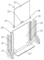
Fig. 1 is a schematic structural view of a composite wall panel for building assembly according to the present invention;
fig. 2 is an exploded schematic view of a composite wall panel for building assembly according to the present invention;
fig. 3 is a schematic structural view of a portion a in fig. 2 of a composite wall panel for building assembly according to the present invention;
fig. 4 is a schematic structural diagram of a connecting mechanism of a composite wall panel for building assembly according to the present invention;
fig. 5 is a schematic structural view of a table folding mechanism of the compound wall panel for building assembly according to the present invention;
fig. 6 is an exploded schematic view of a table folding mechanism of a composite wall panel for building assembly according to the present invention;
fig. 7 is the utility model provides a structural schematic of the storage plate of compound wallboard for building assembly.
Description of the figure numbers:
1. fixing the plate body; 2. installing a plate body; 3. a projecting plate; 4. a table plate folding mechanism; 5. a movable plate; 6. a roller; 7. a storage plate; 8. a connecting mechanism; 9. connecting grooves; 10. a prismatic connecting rod; 11. a limiting plate; 12. a clamping block; 13. a spring; 14. a drive belt; 15. a mounting frame; 16. a chute; 17. a baffle plate; 18. a connecting plate; 19. a first rotating shaft connecting block; 20. a connecting frame; 21. a through groove; 22. a limiting groove; 23. a movable table plate; 24. a groove; 25. a limiting block; 26. a round bar; 27. a storage plate body; 28. a second rotating shaft; 29. a first link; 30. a first belt pulley; 31. a first bevel gear; 32. a second bevel gear; 33. a movable baffle plate.
Detailed Description
The technical solutions in the embodiments of the present invention will be described clearly and completely with reference to the accompanying drawings in the embodiments of the present invention, and it is obvious that the described embodiments are only some embodiments of the present invention, not all embodiments.
In the description of the present invention, it is to be understood that the terms "upper", "lower", "front", "rear", "left", "right", "top", "bottom", "inner", "outer", and the like indicate orientations or positional relationships based on the orientations or positional relationships shown in the drawings, and are only for convenience of description and simplicity of description, and do not indicate or imply that the device or element being referred to must have a particular orientation, be constructed and operated in a particular orientation, and therefore, should not be construed as limiting the present invention.
Example 1:
referring to fig. 1-4, a composite wall panel for building assembly comprises a fixed panel body 1 and an installation panel body 2, wherein the back surfaces of the fixed panel body 1 and the installation panel body 2 are fixedly connected with a protruding plate 3, one side of the protruding plate 3 is provided with a connecting mechanism 8, the other side of the protruding plate 3 is provided with a connecting groove 9, the connecting groove 9 is matched with the connecting mechanism 8 on the adjacent protruding plate 3, and the adjacent fixed panel body 1 or installation panel body 2 is connected with the connecting groove 9 through the connecting mechanism 8; be provided with the installing opening on the mounting plate body 2, the inside fixed mounting of installing opening has table turnover mechanism 4, and the mounting plate body 2 below still is provided with movable receiving mechanism, and movable receiving mechanism is including fly leaf 5, and the bottom fixedly connected with gyro wheel 6 of fly leaf 5, and fixed mounting has the mechanism of stopping that stops of stopping on gyro wheel 6, still is connected with storage plate 7 on the fly leaf 5, is provided with driving belt 14 between storage plate 7 and the table turnover mechanism 4, and driving belt 14 and storage plate 7 and table turnover mechanism 4 phase-match.
The utility model comprises a fixed plate body 1 and an installation plate body 2, the whole wall plate is formed by combining and splicing the fixed plate body 1 and the installation plate body 2, a user can decide the collocation of the fixed plate body 1 and the installation plate body 2 and the position of the installation plate body 2 according to the actual wall surface length, a protruding plate 3 is fixedly connected on the fixed plate body 1 and the installation plate body 2, a connecting mechanism 8 and a connecting groove 9 are arranged on the protruding plate 3, when in use, the number and the position of the fixed plate body 1 and the installation plate body 2 are determined according to the actual requirements, then the connecting groove 9 on the fixed plate body 1 or the installation plate body 2 is aligned to the prismatic connecting rod 10 of the connecting mechanism 8 on the adjacent fixed plate body 1 or the installation plate body 2, the inward pushing is carried out, so that the connecting groove 9 is connected on the prismatic connecting rod 10, in the pushing process, the connecting groove 9 of the protruding plate 3 can enter between the protruding plate 3 and, because be provided with spring 13 between chucking piece 12 and the limiting plate 11, spring 13 receives can produce the answer elasticity after compression deformation to can promote chucking piece 12 and press from both sides adjacent protruding board 3 tightly, utilize above-mentioned design, effectively solved the trouble and the insecure problem of installation of current design fixed mounting.
Example 2:
referring to fig. 5-6, the embodiment 1 is different from the above embodiments;
table turns over a mechanism 4 and is provided with spout 16 including mounting bracket 15 and connecting plate 18, mounting bracket 15 and installation plate body 2 fixed connection on the mounting bracket 15, fixedly connected with baffle 17 between the mounting bracket 15, and connecting plate 18 fixed connection is in the installation opening of installation plate body 2, the first pivot connecting block 19 of fixedly connected with on the connecting plate 18, rotates on the first pivot connecting block 19 and is connected with first pivot.
The table plate folding mechanism 4 further comprises a connecting frame 20, the bottom end of the connecting frame 20 is fixedly connected to the first rotating shaft, a through groove 21 is formed in the connecting frame 20, the through groove 21 is matched with the sliding groove 16, a limiting groove 22 is further formed in the inner wall of the connecting frame 20, a movable table plate 23 is arranged between the limiting grooves 22, and a groove 24 is fixedly connected to the movable table plate 23.
Fixedly connected with stopper 25 on the lower extreme lateral wall of activity table 23, stopper 25 and spacing groove 22 phase-match, fixedly connected with round bar 26 on the stopper 25, round bar 26 with run through groove 21 and spout 16 phase-match, activity table 23 passes through stopper 25 and round bar 26 and mounting bracket 15 and link 20 swing joint.
The utility model is provided with the table plate turnover mechanism 4 on the mounting plate body 2, when in use, the movable table plate 23 is pulled downwards through the groove 24, because the side wall of the movable table plate 23 is fixedly connected with the limit block 25, and the connecting frame 20 is provided with the limit groove 22, the relative rotation between the movable table plate 23 and the connecting frame 20 is ensured, when the movable table plate 23 is pulled to the arc groove position of the sliding groove 16, at this time, due to the limiting effect of the sliding groove 16, the movable table plate 23 cannot descend from the limiting groove 22, the round rod 26 fixedly connected to the limiting block 25 drives the movable table plate 23 and the connecting frame 20 to rotate along the first rotating shaft along the track of the sliding groove 16, and finally the baffle 17 between the movable table plate 23 and the mounting frame 15 is in contact with each other, so that the movable table plate 23 is horizontally placed, and a user can place some ornaments or books and the like by means of the movable table plate 23.
Example 3:
referring to fig. 7; the difference is based on embodiment 1 or 2;
the accommodating plate 7 comprises a storage plate body 27, a second rotating shaft 28 is fixedly connected to the bottom end of the storage plate body 27, the storage plate body 27 is rotatably connected with the movable plate 5 through the second rotating shaft 28, first connecting rods 29 are fixedly connected to two ends of the second rotating shaft 28, a first belt pulley 30 is fixedly connected to the first connecting rods 29, a second belt pulley is rotatably connected to the inside of the first rotating shaft connecting block 19, the second belt pulley is fixedly connected to the first rotating shaft, and the transmission belt 14 is connected to the first belt pulley 30 and the second belt pulley in a surrounding mode; one end of the first connecting rod 29 far away from the second rotating shaft 28 is fixedly connected with a first bevel gear 31, the first bevel gear 31 is meshed with a second bevel gear 32, the second bevel gear 32 is fixedly connected with the top end of the second connecting rod, the lower end of the second connecting rod is rotatably connected on the movable plate 5, a movable baffle 33 is further fixedly connected on the second connecting rod, and the movable baffle 33 is matched with the object placing plate body 27.
The utility model is characterized in that the installation plate body 2 is further provided with a movable plate 5, the movable plate 5 is connected with a containing plate 7, when in use, the movable plate 5 is pulled out through a roller 6 at the bottom of the movable plate 5, then the movable plate 5 is fixed at a proper position through a braking device on the roller 6, because the transmission belt 14 is arranged between the table plate turnover mechanism 4 and the containing plate 7, when a user turns over the movable table plate 23, the transmission belt 14 can drive the containing plate body 27 of the containing plate 7 to turn inwards along the second rotating shaft 28 through the first belt pulley 30, when the second rotating shaft 28 rotates, the two ends of the second rotating shaft 28 are fixedly connected with the first bevel gear 31 to rotate together, the first bevel gear 31 rotates to drive the second bevel gear 32 engaged with the first bevel gear to rotate, the second connecting rod is fixedly connected on the second bevel gear 32, and the second connecting rod is also fixedly connected with a movable baffle 33, the movable baffle 33 also changes the same angle along with the rotation of the second bevel gear 32, when the object placing plate body 27 rotates to the horizontal angle, the movable baffle 33 also rotates to be vertical to the mounting plate body 2, at the moment, the object placing plate body 27 is in contact with the movable baffle 33, so that the movable baffle 33 is ensured to be fixed in the horizontal state, at the moment, sundries and the like can be placed on the object placing plate body 27 and used as a storage cabinet; by utilizing the design, the problems that the existing design structure is simple, only has a decorative effect and has no practical value are effectively solved.
Above, only be the concrete implementation of the preferred embodiment of the present invention, but the protection scope of the present invention is not limited thereto, and any person skilled in the art is in the technical scope of the present invention, according to the technical solution of the present invention and the design of the present invention, equivalent replacement or change should be covered within the protection scope of the present invention.
Claims (6)
1. The utility model provides a double entry wallboard for building assembly, is including fixed plate body (1) and installation plate body (2), its characterized in that: the back surfaces of the fixed plate body (1) and the mounting plate body (2) are fixedly connected with protruding plates (3), one sides of the protruding plates (3) are provided with connecting mechanisms (8), the other sides of the protruding plates (3) are provided with connecting grooves (9), the connecting grooves (9) are matched with the connecting mechanisms (8) on the adjacent protruding plates (3), and the adjacent fixed plate body (1) or mounting plate body (2) is connected with the connecting grooves (9) through the connecting mechanisms (8); be provided with the installing opening on the mounting plate body (2), the inside fixed mounting of installing opening has table to turn over a mechanism (4), the mounting plate body (2) below still is provided with movable receiving mechanism, movable receiving mechanism is including fly leaf (5), bottom fixedly connected with gyro wheel (6) of fly leaf (5), fixed mounting has the braking mechanism on gyro wheel (6), still be connected with storage plate (7) on fly leaf (5), be provided with driving belt (14) between storage plate (7) and the table turns over a mechanism (4), driving belt (14) and storage plate (7) and table turn over a mechanism (4) phase-match.
2. A composite wall panel for building assembly according to claim 1, wherein: coupling mechanism (8) are including prism connecting rod (10), prism connecting rod (10) and spread groove (9) phase-match, prism connecting rod (10) one end fixed connection is on protruding board (3), protruding board (3) one end fixedly connected with limiting plate (11) are kept away from in prism connecting rod (10), sliding connection has chucking piece (12) on prism connecting rod (10), be provided with spring (13) between chucking piece (12) and limiting plate (11), spring (13) cover is connected on prism connecting rod (10), spring (13) one end fixed connection is on limiting plate (11), and other end fixed connection is on chucking piece (12).
3. A composite wall panel for building assembly according to claim 1, wherein: table turns over a mechanism (4) including mounting bracket (15) and connecting plate (18), mounting bracket (15) and installation plate body (2) fixed connection, be provided with spout (16) on mounting bracket (15), fixedly connected with baffle (17) between mounting bracket (15), connecting plate (18) fixed connection is in the installation opening of installation plate body (2), the first pivot connecting block (19) of fixedly connected with on connecting plate (18), it is connected with first pivot to rotate on first pivot connecting block (19).
4. A composite wall panel for building assembly according to claim 1, wherein: the table plate turnover mechanism (4) is characterized by further comprising a connecting frame (20), the bottom end of the connecting frame (20) is fixedly connected to a first rotating shaft, a through groove (21) is formed in the connecting frame (20), the through groove (21) is matched with the sliding groove (16), a limiting groove (22) is further formed in the inner wall of the connecting frame (20), a movable table plate (23) is arranged between the limiting grooves (22), and a groove (24) is fixedly connected to the movable table plate (23).
5. A compound wall panel for building assembly according to claim 4, wherein: fixedly connected with stopper (25) on the lower extreme lateral wall of activity table (23), stopper (25) and spacing groove (22) phase-match, fixedly connected with round bar (26) on stopper (25), round bar (26) with run through groove (21) and spout (16) phase-match, activity table (23) is through stopper (25) and round bar (26) and mounting bracket (15) and link (20) swing joint.
6. A composite wall panel for building assembly according to claim 3, wherein: the storage plate (7) comprises a storage plate body (27), a second rotating shaft (28) is fixedly connected to the bottom end of the storage plate body (27), the storage plate body (27) is rotatably connected with the movable plate (5) through the second rotating shaft (28), first connecting rods (29) are fixedly connected to the two ends of the second rotating shaft (28), a first belt pulley (30) is fixedly connected to the first connecting rods (29), a second belt pulley is rotatably connected to the inner portion of the first rotating shaft connecting block (19), the second belt pulley is fixedly connected to the first rotating shaft, and the transmission belt (14) is connected to the first belt pulley (30) and the second belt pulley in a surrounding mode; one end of the first connecting rod (29) far away from the second rotating shaft (28) is fixedly connected with a first bevel gear (31), the first bevel gear (31) is meshed with a second bevel gear (32), the second bevel gear (32) is fixedly connected with the top end of a second connecting rod, the lower end of the second connecting rod is rotatably connected onto the movable plate (5), the second connecting rod is further fixedly connected with a movable baffle (33), and the movable baffle (33) is matched with the object placing plate body (27).
Priority Applications (1)
| Application Number | Priority Date | Filing Date | Title |
|---|---|---|---|
| CN201921120771.9U CN211974128U (en) | 2019-07-17 | 2019-07-17 | Compound wallboard for building assembly |
Applications Claiming Priority (1)
| Application Number | Priority Date | Filing Date | Title |
|---|---|---|---|
| CN201921120771.9U CN211974128U (en) | 2019-07-17 | 2019-07-17 | Compound wallboard for building assembly |
Publications (1)
| Publication Number | Publication Date |
|---|---|
| CN211974128U true CN211974128U (en) | 2020-11-20 |
Family
ID=73354062
Family Applications (1)
| Application Number | Title | Priority Date | Filing Date |
|---|---|---|---|
| CN201921120771.9U Active CN211974128U (en) | 2019-07-17 | 2019-07-17 | Compound wallboard for building assembly |
Country Status (1)
| Country | Link |
|---|---|
| CN (1) | CN211974128U (en) |
-
2019
- 2019-07-17 CN CN201921120771.9U patent/CN211974128U/en active Active
Similar Documents
| Publication | Publication Date | Title |
|---|---|---|
| WO2019127473A1 (en) | Curtain control device and electric curtain | |
| CN111570209B (en) | Auxiliary gluing equipment for square glass window | |
| CN211974128U (en) | Compound wallboard for building assembly | |
| CN211959790U (en) | Dustproof server cabinet convenient to maintain | |
| CN209855110U (en) | Combined environment-friendly decorative wallboard for indoor design | |
| CN213774015U (en) | Heat-preservation energy-saving building curtain wall | |
| CN217510255U (en) | Connecting structure of upper rail and decorative panel of curtain | |
| CN214541416U (en) | Multi-color curved surface LED display screen based on WIFI intelligent control | |
| CN215804196U (en) | Novel household fireproof door and window convenient to detach | |
| CN210667638U (en) | Portable propaganda device is used in environmental art design | |
| CN201176829Y (en) | Telescopic movable heat insulation wall | |
| CN201850680U (en) | Exposed frame curtain wall system capable of rotating any degrees | |
| CN211900216U (en) | Ventilation device for double-layer curtain wall | |
| CN210459658U (en) | Environment-friendly decoration partition wall convenient to disassemble and assemble | |
| CN211080649U (en) | TV wall structure is used in indoor decoration design | |
| CN211154353U (en) | Display screen lifting equipment | |
| CN213928154U (en) | Backplate based on household electrical appliances complete sets is with installation of being convenient for | |
| CN208685924U (en) | A kind of clean wallboard of food factory's dust proof workshop being easily installed | |
| CN213979692U (en) | Interior design is with beautifying decoration wallboard | |
| CN221373361U (en) | Steel heat-insulating fireproof door | |
| CN106522658B (en) | Door handle | |
| CN213234837U (en) | Passive door and window capable of insulating sound and reducing noise | |
| CN219323285U (en) | Hidden wall type display cabinet | |
| CN216785607U (en) | Material management device for building engineering | |
| CN111425060A (en) | Building enclosure of building engineering |
Legal Events
| Date | Code | Title | Description |
|---|---|---|---|
| GR01 | Patent grant | ||
| GR01 | Patent grant |