CN210482377U - Assembled gallows of utility tunnel pipeline - Google Patents
Assembled gallows of utility tunnel pipeline Download PDFInfo
- Publication number
- CN210482377U CN210482377U CN201920954188.1U CN201920954188U CN210482377U CN 210482377 U CN210482377 U CN 210482377U CN 201920954188 U CN201920954188 U CN 201920954188U CN 210482377 U CN210482377 U CN 210482377U
- Authority
- CN
- China
- Prior art keywords
- anchoring
- utility tunnel
- positioning base
- pipeline
- support arm
- Prior art date
- Legal status (The legal status is an assumption and is not a legal conclusion. Google has not performed a legal analysis and makes no representation as to the accuracy of the status listed.)
- Active
Links
Images


Landscapes
- Supports For Pipes And Cables (AREA)
Abstract
The utility model discloses a utility tunnel pipeline assembled gallows installs in the utility tunnel, sets up along utility tunnel length direction interval for fixed pipeline, including anchor rod, positioning base, slotted adaptor, slip trailing arm and location snap ring, positioning base passes through anchor rod to be fixed in the utility tunnel, positioning base and utility tunnel inner wall are parallel to, and perpendicular to utility tunnel length direction; the sliding support arm is connected to the positioning base through a sliding groove type adapter, the sliding support arm is arranged at intervals along the positioning base and is perpendicular to the positioning base, the positioning clamping rings are arranged at intervals on the sliding support arm, and the pipeline is fixed to the sliding support arm through the positioning clamping rings. The utility model discloses a vertical height's of pipeline regulation is realized in the upper and lower slip of location base, realizes the horizontally regulation of pipeline through location snap ring horizontal slip to job site full assembly, zero welding can increase substantially the efficiency of construction, reduce construction cost, and reduce later stage fortune dimension cost.
Description
Technical Field
The utility model relates to a pipe rack gallows technical field, concretely relates to a gallows is propped up to utility tunnel pipeline assembled.
Background
The urban underground comprehensive pipe gallery is a tunnel space built underground in a city, and integrates various engineering pipelines such as electric power, communication, gas, heat supply, water supply and drainage and the like, so that unified planning, unified design, unified construction and management are realized. For intensive utilization underground space, most pipelines are arranged comprehensively through a gallows, consequently, a gallows of utility tunnel and construction technology become one of utility tunnel's core technique.
Among the utility model discloses a utility tunnel gallows construction technology, the ubiquitous following technical problem: firstly, the pre-buried base has poor anti-overturning capability, inaccurate pre-buried positioning and poor installation precision; secondly, the bracket arm is single in form, and the pipeline installation specification is limited; thirdly, the horizontal position of the pipeline on the supporting arm cannot be adjusted, and the pipeline is locally concentrated in stress and even damaged due to long-time accumulated deformation, so that the service life of the pipeline is seriously influenced, and the later maintenance cost of the comprehensive pipe gallery is greatly increased; and fourthly, the bracket arm and the base are mostly connected by welding, the construction efficiency and the installation quality of the on-site pipeline are seriously influenced, and the construction cost is improved. The utility model provides a utility tunnel pipeline assembled gallows will solve that the pre-buried base antidumping ability among traditional utility tunnel gallows construction technology is poor, pre-buried position is difficult to control, the trailing arm form is single, the pipeline specification is limited, the fixed difficulty of pipeline, the vertical and level of pipeline are to the unable adjustment of position, the installation accuracy is low, the field welding work volume is big, the level of assemblization is low, the efficiency of construction is low, the construction cost is high and construction quality is difficult to the technical problem who guarantees.
SUMMERY OF THE UTILITY MODEL
The utility model provides a pipe gallery pipeline assembled gallows assembles at the job site, easy operation, and the connection is reliable.
The utility model provides a technical scheme that above-mentioned technical problem adopted is:
a fabricated support and hanger for a pipeline of a comprehensive pipe rack is installed in the comprehensive pipe rack, is arranged at intervals along the length direction of the comprehensive pipe rack, is used for fixing the pipeline, and comprises an anchoring rod, a positioning base, a sliding groove type adapter, a sliding support arm and a positioning snap ring, wherein the positioning base is fixed in the comprehensive pipe rack through the anchoring rod, and is parallel to the inner wall of the comprehensive pipe rack and perpendicular to the length direction of the comprehensive pipe rack; the pipeline fixing device is characterized in that the sliding support arm is connected to the positioning base through a sliding groove type adapter, the sliding support arm is arranged at intervals along the positioning base and is perpendicular to the positioning base, the positioning clamping rings are arranged at intervals on the sliding support arm, and the pipeline is fixed to the sliding support arm through the positioning clamping rings.
Furthermore, the positioning base is a rectangular frame, the middle of one side surface of the positioning base is provided with an opening along the length direction, the end part of the opening is bent inwards by 90 degrees and forms an anchoring block with a side plate of the positioning base in a surrounding manner, and a sliding chute is formed between the two anchoring blocks; the other side of location base sets up the fixed orifices along length direction interval, the fixed orifices cooperates with the anchor pole, set up the anchor hole along length direction interval on the anchor piece.
Furthermore, the chute type adapter is formed by fixing two strip-shaped plates with F-shaped cross sections through a connecting plate arranged in the middle of the strip-shaped plates, each strip-shaped plate comprises a back plate and two anchoring wing plates positioned at the same end part of the back plate, and the two strip-shaped plates are arranged oppositely; the space between the two anchoring wing plates is matched and fixed with the anchoring block; the two back plates and the connecting plate vertical to the back plates are encircled to form an anchoring end.
Furthermore, the sliding support arm is a hollow cuboid, two slide ways are arranged on the upper surface of the sliding support arm, one end of the sliding support arm is a connecting end, and the connecting end is sleeved outside the anchoring end and fixed with the anchoring end.
Further, the location snap ring includes clamp and spacing end, the clamp is C shape, and its both ends are equipped with spacing end, spacing end is fixed on the slip trailing arm, the location snap ring slides along the slide of slip trailing arm.
Furthermore, two anchoring wing plates of the sliding groove type adapter correspond to two anchoring blocks of the positioning base one by one, the sliding groove type adapter is adjusted in a sliding mode along a sliding groove in the positioning base and is fixed through an anchoring nail after being in place; the connecting end of the sliding support arm is fixed on the anchoring end through an anchoring nail.
Further, the anchoring blocks and the anchoring ends are filled with anchoring materials.
Furthermore, the material of location base, slotted adaptor and slip trailing arm is the steel sheet, the location snap ring is flexible material.
Furthermore, the positioning snap ring is connected with the sliding support arm in a buckling mode.
Further, the anchoring material is a high-strength anchoring agent.
The utility model discloses beneficial effect as follows:
the anchoring rod is arranged on the positioning base, so that the anti-overturning capacity is greatly improved, and the embedded base is accurately positioned by adjusting the position and the length of the anchoring rod;
the sliding groove type adapter is adopted to slide on the sliding groove of the positioning base, so that the sliding support arm can be randomly adjusted in the vertical position, and the installation precision of the pipeline is improved;
the positioning snap ring is adopted to slide on the sliding support arm, so that the pipeline can be randomly adjusted on the horizontal position of the support arm, the installation precision is improved, and the snap-fit connection is adopted, so that the operation is simple, and the construction efficiency is improved;
the positioning base and the sliding support arm are mounted in a fully-assembled manner through the sliding groove type adapter, welding connection is avoided, and the connection mode is simple and convenient;
the components are connected by adopting the anchoring holes and the anchoring nails, so that the method is safe and reliable, simple to operate and convenient to construct;
the utility model discloses application scope is wide, and job site is assembly, zero welding entirely, can increase substantially the efficiency of construction, reduce construction cost to reduce later stage fortune dimension cost.
Drawings
Fig. 1 is a schematic view of the assembly state of the present invention;
FIG. 2 is a schematic view of the positioning base structure of the present invention;
fig. 3 is a top view of the positioning base of the present invention;
fig. 4 is a schematic structural view of the sliding groove type adaptor of the present invention;
fig. 5 is a side view of the sliding groove type adaptor of the present invention
Fig. 6 is a schematic structural view of the sliding bracket arm of the present invention;
fig. 7 is a schematic structural view of the positioning snap ring of the present invention;
FIG. 8 is a top view of the positioning snap ring of the present invention
Fig. 9 is a schematic connection diagram of the sliding-groove adapter of the present invention;
fig. 10 is a schematic view of the connection of the positioning snap ring of the present invention.
Reference numerals: 1-an anchoring rod, 2-a positioning base, 21-a quick anchoring part, 22-a chute, 23-a fixing hole, 3-a chute type adaptor, 31-an anchoring wing plate, 32-an anchoring end, 4-a sliding bracket, 41-a slideway, 42-a connecting end, 5-a positioning snap ring, 51-a hoop and 52-a limiting end.
Detailed Description
The technical solutions in the embodiments of the present invention will be described clearly and completely with reference to the accompanying drawings, and obviously, the described embodiments are only some embodiments, not all embodiments, of the present invention. Based on the embodiments in the present invention, all other embodiments obtained by a person skilled in the art without creative work belong to the protection scope of the present invention.
As shown in fig. 1-10, an assembly type support hanger for a pipeline of a utility tunnel is installed in the utility tunnel, is arranged at intervals along the length direction of the utility tunnel, and is used for fixing the pipeline, and comprises an anchoring rod 1, a positioning base 2, a sliding groove type adapter 3, a sliding bracket 4 and a positioning snap ring 5, wherein the positioning base 2 is fixed in the utility tunnel through the anchoring rod 1, and the positioning base 2 is parallel to the inner wall of the utility tunnel and is perpendicular to the length direction of the utility tunnel; the pipeline fixing device is characterized in that the sliding support arm 4 is connected to the positioning base 2 through the sliding groove type adapter 3, the sliding support arm 4 is arranged at intervals along the positioning base 2 and is perpendicular to the positioning base 2, the positioning clamping ring 5 is arranged at intervals on the sliding support arm 4, and the pipeline is fixed to the sliding support arm 4 through the positioning clamping ring 5. This embodiment is preferred, 2 vertical settings of location base, anchor rod 1 through upper and lower interval setting is fixed on utility tunnel's inner wall, interval sets up two about the slip trailing arm 4, and the interval sets up 3 location snap rings 5 on every slip trailing arm 4.
Preferably, the anchoring rod 1 is a high-strength bolt, the specification and the size and the number of the bolts are selected according to the design requirements during actual construction, and the bolts are purchased according to standard specifications during use.
As shown in fig. 2, further, the positioning base 2 is a rectangular frame, the middle of one side surface is opened along the length direction, the end part of the opened position is bent inward by 90 degrees and forms an anchoring block 21 with the side plate of the positioning base 2, and a sliding groove 22 is formed between the two anchoring blocks 21; fixing holes 23 are formed in the other side face of the positioning base 2 at intervals along the length direction, the fixing holes 23 are matched with the anchoring rods 1, and anchoring holes are formed in the anchoring blocks 21 at intervals along the length direction. Preferably, the positioning base 2 is formed by bending a steel plate.
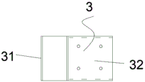
As shown in fig. 3, 4 and 5, further, the chute-type adaptor 3 is formed by fixing two strip-shaped plates with F-shaped cross sections through a connecting plate arranged in the middle of the strip-shaped plates, each strip-shaped plate comprises a back plate and two anchoring wing plates 31 located at the same end of the back plate, and the two strip-shaped plates are arranged oppositely; the space between the two anchoring wing plates 31 is matched and fixed with the anchoring block 21; the two backplates enclose a web perpendicular to the backplates to form an anchor end 32. Preferably, the sliding groove type adaptor 3 is formed by welding steel plates.
As shown in fig. 6, further, the sliding bracket arm 4 is a hollow rectangular parallelepiped, two slide ways 41 are provided on the upper surface of the sliding bracket arm, one end of the sliding bracket arm 4 is a connection end 42, and the connection end 42 is sleeved outside the anchoring end 32 and fixed thereto. Preferably, the sliding bracket arm 4 is formed by bending a steel plate.
As shown in fig. 7 and 8, further, the positioning snap ring 5 includes a clamp 51 and a limiting end 52, the clamp 51 is C-shaped, the limiting end 52 is disposed at two ends of the clamp, the limiting end 52 is fixed on the sliding bracket arm 4, and the positioning snap ring 5 slides along the slide way 41 of the sliding bracket arm 4. The limiting end 52 is provided with a flexible buckle which is connected with the buckle of the slideway 41 of the sliding bracket arm 4. Preferably, the specification and the size of the positioning snap ring 5 are matched with those of the pipeline.
As shown in fig. 9, further, two anchoring wing plates 31 of the sliding groove type adaptor 3 correspond to two anchoring blocks 21 of the positioning base 2 one by one, and the sliding groove type adaptor 3 is adjusted in a sliding manner along the sliding groove 22 on the positioning base 2 and fixed by an anchoring nail after being in place; the connecting end 42 of the sliding bracket arm 4 is fixed on the anchoring end 32 through an anchoring nail. The upper and lower positions of the sliding support arm 4 are adjusted by sliding the sliding support arm 4 up and down on the positioning base 2 through the sliding groove type adapter 3, and the adjustment is flexible and convenient in cooperation with the installation and placement of pipelines.
Further, the anchoring block 21 and the anchoring end 32 are filled with an anchoring material.
Furthermore, the positioning base 2, the chute type adaptor 3 and the sliding bracket arm 4 are made of steel plates, and the positioning clamping ring 5 is made of flexible materials.
As shown in fig. 10, further, the positioning snap ring 5 is connected with the sliding bracket arm 4 in a snap-fit manner.
Further, the anchoring material is a high-strength anchoring agent. Preferably, the anchoring rod 1, the anchoring nail and the anchoring material are all finished products which are purchased in the market and meet the standard specification.
A construction method of an assembly type supporting and hanging frame for a comprehensive pipe gallery pipeline comprises the following steps:
s1, prefabricating the assembly: prefabricating a positioning base 2, a sliding groove type adapter piece 3, a sliding bracket arm 4 and a positioning clamping ring 5 according to design requirements;
s2, purchasing standard parts: according to design requirements, purchasing an anchoring rod 1 and an anchoring nail;
s3, mounting and positioning the base 2: fixing the anchoring rod 1 on the positioning base 2 through a fixing hole 23, adjusting the position and the extension length of the anchoring rod 1, and reserving an operation hole on the positioning base 2;
s4, mounting the chute adaptor 3: clamping the chute type adaptor 3 into the positioning base 2 through a reserved operation hole, matching the two anchoring wing plates 31 with the two anchoring blocks 21 respectively, adjusting the chute type adaptor 3 to a proper position, and fixing by using anchoring nails;
and S5, mounting the sliding bracket arm 4: sleeving the connecting end 42 of the sliding bracket arm 4 on the anchoring end 32 of the sliding groove type adaptor 3, and fixing by using an anchoring nail;
s6, laying a pipeline: laying a pipeline on the sliding bracket arm 4 according to the design requirement;
s7, fixing and adjusting the pipeline: installing a positioning clamp ring 5 with a corresponding model on the pipeline, and fixing the positioning clamp ring 5 and the sliding bracket arm 4 after the position of the pipeline is adjusted;
s8, plugging the operation hole: and after the pipeline is installed and debugged, plugging the reserved operating hole.
It is obvious to a person skilled in the art that the invention is not restricted to details of the above-described exemplary embodiments, but that it can be implemented in other specific forms without departing from the spirit or essential characteristics of the invention. The present embodiments are therefore to be considered in all respects as illustrative and not restrictive, the scope of the invention being indicated by the appended claims rather than by the foregoing description, and all changes which come within the meaning and range of equivalency of the claims are therefore intended to be embraced therein, and any reference signs in the claims are not intended to be construed as limiting the claim concerned.
Claims (10)
1. The utility model provides a utility tunnel pipeline assembled gallows, installs in the utility tunnel, sets up along utility tunnel length direction interval for fixed pipeline, characterized by, including anchor rod (1), location base (2), slotted adaptor (3), slip trailing arm (4) and location snap ring (5), location base (2) are fixed in the utility tunnel through anchor rod (1), location base (2) are parallel with the utility tunnel inner wall, and perpendicular to utility tunnel length direction; the pipeline fixing device is characterized in that the sliding support arm (4) is connected to the positioning base (2) through a sliding groove type adapter (3), the sliding support arm (4) is arranged at intervals along the positioning base (2) and is perpendicular to the positioning base (2), the positioning clamping ring (5) is arranged at intervals on the sliding support arm (4), and the pipeline is fixed to the sliding support arm (4) through the positioning clamping ring (5).
2. The utility tunnel pipe fabricated support and hanger of claim 1, wherein: the positioning base (2) is a rectangular frame, the middle of one side face of the positioning base is provided with an opening along the length direction, the end part of the opening is bent inwards by 90 degrees and forms an anchoring block (21) with a side plate of the positioning base (2) in a surrounding manner, and a sliding groove (22) is formed between the two anchoring blocks (21); another side of location base (2) sets up fixed orifices (23) along length direction interval, fixed orifices (23) and anchor pole (1) cooperation, set up the anchor hole along length direction interval on anchor piece (21).
3. The utility tunnel pipe fabricated support and hanger of claim 2, wherein: the sliding groove type adapter (3) is formed by fixing two strip-shaped plates with F-shaped cross sections through a connecting plate arranged in the middle of the strip-shaped plates, each strip-shaped plate comprises a back plate and two anchoring wing plates (31) positioned at the same end part of the back plate, and the two strip-shaped plates are arranged in a back-to-back manner; the space between the two anchoring wing plates (31) is matched and fixed with the anchoring block (21); the two back plates and the connecting plate vertical to the back plates are enclosed to form an anchoring end (32).
4. The utility tunnel pipe fabricated support and hanger of claim 3, wherein: the sliding support arm (4) is a hollow cuboid, two slide ways (41) are arranged on the upper surface of the sliding support arm, one end of the sliding support arm (4) is a connecting end (42), and the connecting end (42) is sleeved outside the anchoring end (32) and fixed with the anchoring end.
5. The utility tunnel pipe fabricated support and hanger of claim 4, wherein: location snap ring (5) include clamp (51) and spacing end (52), clamp (51) are C shape, and its both ends are equipped with spacing end (52), spacing end (52) are fixed on slip trailing arm (4), slide (41) along slip trailing arm (4) slide in location snap ring (5).
6. The utility tunnel pipe fabricated support and hanger of claim 5, wherein: the two anchoring wing plates (31) of the sliding groove type adapter piece (3) correspond to the two anchoring blocks (21) of the positioning base (2) one by one, and the sliding groove type adapter piece (3) is adjusted in a sliding mode along the sliding groove (22) on the positioning base (2) and fixed through the anchoring nail after being in place; the connecting end (42) of the sliding bracket arm (4) is fixed on the anchoring end (32) through an anchoring nail.
7. The utility tunnel pipe fabricated support and hanger of claim 4, wherein: the anchoring block (21) and the anchoring end (32) are filled with anchoring materials.
8. The utility tunnel pipe fabricated support and hanger of claim 1, wherein: the positioning base (2), the chute type adaptor (3) and the sliding support arm (4) are made of steel plates, and the positioning clamping ring (5) is made of flexible materials.
9. The utility tunnel pipe fabricated support and hanger of claim 5, wherein: the positioning snap ring (5) is connected with the sliding support arm (4) in a buckling mode.
10. The utility tunnel pipe fabricated support and hanger of claim 7, wherein: the anchoring material is an anchoring agent.
Priority Applications (1)
| Application Number | Priority Date | Filing Date | Title |
|---|---|---|---|
| CN201920954188.1U CN210482377U (en) | 2019-06-24 | 2019-06-24 | Assembled gallows of utility tunnel pipeline |
Applications Claiming Priority (1)
| Application Number | Priority Date | Filing Date | Title |
|---|---|---|---|
| CN201920954188.1U CN210482377U (en) | 2019-06-24 | 2019-06-24 | Assembled gallows of utility tunnel pipeline |
Publications (1)
| Publication Number | Publication Date |
|---|---|
| CN210482377U true CN210482377U (en) | 2020-05-08 |
Family
ID=70514576
Family Applications (1)
| Application Number | Title | Priority Date | Filing Date |
|---|---|---|---|
| CN201920954188.1U Active CN210482377U (en) | 2019-06-24 | 2019-06-24 | Assembled gallows of utility tunnel pipeline |
Country Status (1)
| Country | Link |
|---|---|
| CN (1) | CN210482377U (en) |
Cited By (2)
| Publication number | Priority date | Publication date | Assignee | Title |
|---|---|---|---|---|
| CN113323012A (en) * | 2021-04-21 | 2021-08-31 | 石峰 | Urban pipe gallery adopting porous pre-buried channel support system |
| CN113789810A (en) * | 2021-09-03 | 2021-12-14 | 中交投资南京有限公司 | Prefabricated assembly type pipe gallery and construction method thereof |
-
2019
- 2019-06-24 CN CN201920954188.1U patent/CN210482377U/en active Active
Cited By (3)
| Publication number | Priority date | Publication date | Assignee | Title |
|---|---|---|---|---|
| CN113323012A (en) * | 2021-04-21 | 2021-08-31 | 石峰 | Urban pipe gallery adopting porous pre-buried channel support system |
| CN113323012B (en) * | 2021-04-21 | 2022-07-12 | 李进城 | Urban pipe gallery adopting porous pre-buried channel support system |
| CN113789810A (en) * | 2021-09-03 | 2021-12-14 | 中交投资南京有限公司 | Prefabricated assembly type pipe gallery and construction method thereof |
Similar Documents
| Publication | Publication Date | Title |
|---|---|---|
| CN210482377U (en) | Assembled gallows of utility tunnel pipeline | |
| CN109706959B (en) | Installation method of groove type embedded part in underground comprehensive pipe gallery | |
| CN210857774U (en) | Roof light framework plate installation device | |
| CN204113295U (en) | A kind of municipal shield tunnel | |
| CN113882565B (en) | Assembly type unit ceramic brick dry-hanging curtain wall system and construction method thereof | |
| CN210661648U (en) | Overhead heat distribution pipeline assembly | |
| CN209398923U (en) | Segmental timbering | |
| CN210623800U (en) | Pipe gallery supporting and hanging frame | |
| CN209817181U (en) | Assembled partition wall structure | |
| CN111005744B (en) | Support beam structure of municipal shield tunnel | |
| CN210372300U (en) | Overhead heat distribution pipeline assembly | |
| CN208123629U (en) | Outdoor overhead lifting pipeline equipment | |
| CN110593398B (en) | Underground building for assembly construction and construction method thereof | |
| CN115094691A (en) | Positioning frame for pre-buried sleeve of track bolt | |
| CN209608264U (en) | A kind of temporary cable holder device of foldable turnover | |
| CN210315660U (en) | Utility tunnel supporting structure | |
| CN111980052A (en) | Electric power construction pile foundation structure | |
| CN220957538U (en) | A shield tunnel total station installation device | |
| CN216312618U (en) | Special pipeline clamp for cable bridge | |
| CN213741458U (en) | Fixing device is used in municipal works drainage pipe construction | |
| CN204113299U (en) | A kind of municipal tunnel | |
| CN222542187U (en) | A road construction isolation device | |
| CN220957501U (en) | Roofing-based permanent-face combined eagle eye equipment | |
| CN215519504U (en) | Thickness adjusting device for concrete protective layer of steel bar net frame and pouring forming structure of thickness adjusting device | |
| CN214687109U (en) | Quick installation mould of cable pit capping |
Legal Events
| Date | Code | Title | Description |
|---|---|---|---|
| GR01 | Patent grant | ||
| GR01 | Patent grant |