CN202835241U - Illuminated headgear and light sockets for mounting to the headgear - Google Patents
Illuminated headgear and light sockets for mounting to the headgear Download PDFInfo
- Publication number
- CN202835241U CN202835241U CN2010900008456U CN201090000845U CN202835241U CN 202835241 U CN202835241 U CN 202835241U CN 2010900008456 U CN2010900008456 U CN 2010900008456U CN 201090000845 U CN201090000845 U CN 201090000845U CN 202835241 U CN202835241 U CN 202835241U
- Authority
- CN
- China
- Prior art keywords
- brim
- light
- shade
- light source
- illuminated
- Prior art date
- Legal status (The legal status is an assumption and is not a legal conclusion. Google has not performed a legal analysis and makes no representation as to the accuracy of the status listed.)
- Expired - Lifetime
Links
Images


Classifications
-
- A—HUMAN NECESSITIES
- A42—HEADWEAR
- A42B—HATS; HEAD COVERINGS
- A42B1/00—Hats; Caps; Hoods
- A42B1/24—Hats; Caps; Hoods with means for attaching articles thereto, e.g. memorandum tablets or mirrors
- A42B1/242—Means for mounting detecting, signalling or lighting devices
- A42B1/244—Means for mounting lamps
-
- F—MECHANICAL ENGINEERING; LIGHTING; HEATING; WEAPONS; BLASTING
- F21—LIGHTING
- F21L—LIGHTING DEVICES OR SYSTEMS THEREOF, BEING PORTABLE OR SPECIALLY ADAPTED FOR TRANSPORTATION
- F21L4/00—Electric lighting devices with self-contained electric batteries or cells
- F21L4/02—Electric lighting devices with self-contained electric batteries or cells characterised by the provision of two or more light sources
- F21L4/022—Pocket lamps
- F21L4/027—Pocket lamps the light sources being a LED
-
- F—MECHANICAL ENGINEERING; LIGHTING; HEATING; WEAPONS; BLASTING
- F21—LIGHTING
- F21V—FUNCTIONAL FEATURES OR DETAILS OF LIGHTING DEVICES OR SYSTEMS THEREOF; STRUCTURAL COMBINATIONS OF LIGHTING DEVICES WITH OTHER ARTICLES, NOT OTHERWISE PROVIDED FOR
- F21V21/00—Supporting, suspending, or attaching arrangements for lighting devices; Hand grips
- F21V21/08—Devices for easy attachment to any desired place, e.g. clip, clamp, magnet
- F21V21/088—Clips; Clamps
- F21V21/0885—Clips; Clamps for portable lighting devices
-
- F—MECHANICAL ENGINEERING; LIGHTING; HEATING; WEAPONS; BLASTING
- F21—LIGHTING
- F21Y—INDEXING SCHEME ASSOCIATED WITH SUBCLASSES F21K, F21L, F21S and F21V, RELATING TO THE FORM OR THE KIND OF THE LIGHT SOURCES OR OF THE COLOUR OF THE LIGHT EMITTED
- F21Y2115/00—Light-generating elements of semiconductor light sources
- F21Y2115/10—Light-emitting diodes [LED]
Landscapes
- Engineering & Computer Science (AREA)
- General Engineering & Computer Science (AREA)
- Illuminated Signs And Luminous Advertising (AREA)
- Helmets And Other Head Coverings (AREA)
- Non-Portable Lighting Devices Or Systems Thereof (AREA)
- Radiation-Therapy Devices (AREA)
Abstract
A hands-free lighting, components thereof, and other accessories in combination with the hands-free lighting are provided. The utility model provides a lamp stand that illumination headgear and be used for installing headgear. The hands-free lighting is preferably an illuminating headwear, including a hat or visor or other headwear. The hands-free lighting may include a plurality of light sources positioned on the brim of the lighted hat and configured to provide beams of illumination along different axes to illuminate near and far distances from the wearer while maintaining the natural and streamlined appearance of the lighted hat.
Description
Cross reference to related application
The application requires the priority of No. 61/156,464, the U.S. Provisional Application submitted on February 27th, 2009, with above-mentioned application complete being combined in herein by reference.International Application PCT/US08/87542 number the part continuation application that the application or on December 18th, 2008 submit, this international application requires the U.S. Provisional Application 61/014 submitted on December 18th, 2007, No. 726 priority is with above-mentioned application complete being combined in herein by reference.
Technical field
The field of the utility model relates to hands-free (hands free) lighting device is specifically related to provide for the wearer Cap with lighting apparatus of illumination, illumination head gear and be used for being installed to lamp socket on the head gear.
Background technology
Usually individual demand focuses on to illuminate the lamp in a zone when executing the task, or points to the basically lamp of forward direction for visibility along its sight line.Hand-held torch is a kind of selection, but this lighting device is usually heavy and can disturb ongoing task, because only have a hand to can be used for this task, reason is that the another hand grips torch.As a result, need a kind of hands-free illumination, thereby both hands can be used for all executing the task under lighting condition.
Existing such head gear, it can comprise attached light source in order to illuminate the interior zone of wearer's sight line.This light source can be the LED that is installed to the shade part of baseball style cap.Substantially, these caps have LED, are used for guiding forward light LED axis to be parallel to front and back shade axis from shade thereby install.For these caps, if the wearer wishes to illuminate the object that is positioned at a distance of wearer's specific location, the wearer must move its whole head or cap to point to this certain objects with shade with from the light that it sends.If object is positioned at a distance, then the wearer can come guiding illumination by mobile cap, so that shade substantially flatly or be parallel to ground and extend to provide light beam to illuminate object or zone at a distance.That if object is positioned at is neighbouring, near and be lower than wearer's face, then the wearer must move down shade to down position, thus cap provides light beam to illuminate nearer object.Usually, move down cap and need crooked its neck of wearer.This motion is not expected, because this is uncomfortable for some.
For example, Johnson's (Johnson) United States Patent (USP) discloses a kind of Cap with lighting apparatus 5,741, No. 060, and it has two lamps, and these two lamps are connected to the installing plate that is fixed in cap shade outer lower face.Light source all is fixing, thus its projection light forward.If the wearer wishes to regulate illumination it is guided to another direction, then the wearer still must upwards, downwards, to the left or to the right direction tilt its head or cap itself.These lamps also are suspended on significantly bongrace part below and comprise the relatively large socket that is welded on the installing plate.Installing plate and socket be the outside bottom that is connected to the bongrace part all, and can easily be seen by the third party beholder, thereby produces not attractive in appearance and factitious outward appearance.The lamp that these are large and heavy and the external device (ED) of socket also can drop in wearer's the peripheral vision, and this can disturb and/or even the vision that can stop or interfere the wearer.In addition, because these lamps are fixed, illumination is only available on cap wearer's overall forward direction.
In another example, the United States Patent (USP) of Adolfo Urso (Urso) discloses a kind of lamp 6,056, No. 413, and it is connected to the bongrace (visor) of baseball style cap.The lamp of Adolfo Urso is the bulb that is received in the socket, and this lamp is pivotally connected to the downside of bongrace.Pivotal mounting allows this lamp to provide illumination to throw light in downward or upward direction rotation with the position of selecting to the wearer.This structure allows the wearer that light is focused on forward direction directly providing illumination in wearer the place ahead, or rotates up this light source downwards and provide illumination with the position below bongrace.Rotating lamp is not expected, because its moving-member of having introduced complexity and may break down in reusing in cap.Although the lamp of Adolfo Urso is rotatable, it still is merely able on any one time to a position or regional projection light.Be similar to Johnsonian cap, the same volume of the lamp of Adolfo Urso is large also to be suspended under the bongrace significantly.The large profile of this lamp and erecting device can stop or disturb wearer's vision similarly, and produce inaesthetic outward appearance to the third party who watches this Cap with lighting apparatus, particularly when lamp rotates.In addition, Adolfo Urso is installed in power supply and switch in the crown part of cap, and the Pivot joint that light source is striden in wiring betwixt extends.Along with passage of time, the wiring of striding the Pivot joint extension may be owing to the repeated flex when lamp rotates up and down breaks down.
In another example, the United States Patent (USP) of Peng Musi (Pomes) has been described a kind of baseball cap 6,994, No. 445, and it has the light source at cap shade partial interior.In one embodiment, light source be installed in the depression cabin in the shade in case with respect to the front and back axis of shade towards level or parallel position.The light that is provided by light source with the reflection of the downward direction below shade in the cabin is provided reflector.Require illuminating bundle to be reflected indirect lighting can only be provided, compare with the illuminating bundle that is directly sent by light source inaccuracy and more be difficult to control and guidance of this illumination.In another example, Peng Musi discloses a kind of light source, and its front and back axis that is orthogonal to shade vertically is installed in the depression, thereby light source points to downward direction with respect to shade.For allow this light source at this vertically in being engaged in shade, Peng Musi has instructed shade can have reinforcement to be used for receiving light source with slot milling.Because Peng Musi has described vertically towards installing but still be enclosed in light source in the shade position, the profile of shade can be thicker than needed thickness, thereby does not have the thin outward appearance of typical stream line style of existing baseball cap.In addition, light source with respect to shade vertically towards providing illumination in downward direction, only illuminate the zone that is located immediately at bongrace below.The structure of Peng Musi can not illuminate the reading that is positioned at wearer the place ahead or the object at viewing distance place ideally.In addition, the projection light that is located immediately at bongrace below as in the Peng Musi patent also can cause dazzle or project light onto in wearer's the eyes.
The utility model content
In one aspect, disclose a kind of illumination head gear, wherein a plurality of light sources are installed to head gear, and being used for equipping at least two zoness of different or at least two different directions from the head provides outside illumination.In one form, light source is installed to the shade of head gear and towards being suitable for relative to each other providing outside illumination with different angles.A light source can be one or more LED, and this LED is installed as to shade the place ahead guiding illumination and provides illuminating bundle to the zone that is positioned at relatively away from the distance of cap.Another light source can be one or more LED, and this LED is installed on the shade and towards being suitable for with respect to the first illuminating bundle downwards and intersect the angle guiding illumination light beam of (transverse), thereby provides illumination to the zone that is positioned near cap.This Cap with lighting apparatus advantageously allows the wearer to illuminate in the zone at nearly operating distance such as the reading distance place in wearer the place ahead, or illuminates simultaneously at a distance of the zone of wearer than distant location, and does not need the cap wearer to move cap or rotation light source.
In another form, disclose and a kind ofly be installed to the lamp socket of head gear and have the head gear that is installed to the lamp socket on it.This lamp socket can be installed to the shade of head gear, with specific towards on fixed light source.In one aspect, this lamp socket comprises that one or more lamps of base portion being installed and being extended with the oblique angle that dips down that leaves base portion keep oblique section (bezel) or module.Lamp holder or oblique section size are suitable for receiving light source, and in a kind of scheme, keep a plurality of light sources with respect to base portion with identical constant cant angle.Therefore, this lamp socket advantageously allows in fast and convenient mode a plurality of light sources to be fixed to head gear, one of them above light source towards equidirectional to provide illumination in downward-sloping direction.On the other hand, the relative thin compact of optical module.This allows lamp socket to keep not discernable to a great extent, allow cap to keep streamlined and natural look thereby compare with the existing cap of Johnson, Adolfo Urso and Peng Musi, and those existing caps need the large volume module of shade outside or thick shade to hold enough greatly to hold therein the depression of light source.To this, slim lamp socket allows its inside that is installed in the shade structure, between shade Embedded Division and covering fabric, or outside and do not disturb the functional or outward appearance of head gear at covering fabric.
In one form, lamp socket is connected to Cap with lighting apparatus by being positioned at installation sticking patch part or other installation surface on the head gear shade such as the part along the covering that extends around shade.Therefore, in a kind of scheme, lamp socket and its lamp are fixed to the installation sticking patch that forms at the shade covering rather than the shape of shade keeps Embedded Division.This installation sticking patch preferably has the thickness greater than the shade mantle thickness, has more rigidity or harder lamp socket installation site to form firmly and preferably to compare with thinner shade covering.This lamp socket preferably is fixed to covering with adhesive, and sticking patch is installed is advantageously kept the outer surface of shade covering not have residual adhesive, otherwise adhesive tends to permeate the thinner covering that is usually used in shade, such as fabric.In this way, sticking patch is installed by preventing adhesive wicking (wicking) and/or being penetrated in the shade covering, is prevented from forming stain or stain at the outer surface of shade covering.In one example, sticking patch being installed can be by preventing that adhesive permeation from making to the not wick material in the shade covering.In another example, sticking patch being installed can be to prevent that adhesive from passing through the thick material layer that the shade covering leaks.For example, it can be the sewing parts of embroidery that sticking patch is installed, and it can be made and be stitched by wick material not and mend in order to extend through the shade textile coverings to be thicker than textile coverings.To this, the sewing parts of embroidery provide additional benefit, can provide fabulous position to be used for comprising that can stitch mark such as the logo of mending therein, brand name etc. is used for the sales promotion purpose.
Description of drawings
Fig. 1 is the side view cutaway drawing of the shade of Cap with lighting apparatus, and it has and is installed on it with at the LED of projecting beam on the forward direction and be installed on it so that the LED of illumination to be provided in downward direction;
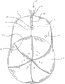
Fig. 2 is the upward view of the shade of Cap with lighting apparatus, and it has along the LED of shade periphery edge location and the LED that locates in the centre position along the front and back axis below shade;
Fig. 3 is the imperfect side view of shade shown in Figure 2, illustrate be positioned the shade periphery edge forward direction the LED of illumination is provided and below the centre position is positioned shade with respect to the LED of shade to tilt to lower angle;
Fig. 4 is the side isometric view of Cap with lighting apparatus, and it has and is positioned at the shade periphery edge with a LED that illumination is provided in forward direction and is positioned at the shade periphery edge so that the 2nd LED of illumination to be provided in downward direction;
Fig. 5 is the face upwarding stereogram of Cap with lighting apparatus, illustrates for the lamp socket that LED is installed to the shade bottom and the LED that is positioned at the shade periphery edge;
Fig. 6 is the stereogram with lamp socket of thin installation base portion, this base portion comprises along base portion two toroidal shell parts at interval each other, this toroidal shell partial configuration for therein with fixing towards receiving LED to provide illumination in the direction that intersects with the base portion plane;
Fig. 7 is the upward view of lamp socket;
Fig. 8 is the side view of lamp socket, thin installation base portion is shown and extends below base portion is installed with one in the toroidal shell part that receives therein LED, and extend above and base portion is installed with the projection of at least end that receives LED;
Fig. 9 is the top view of lamp socket, illustrates along each other two projections at interval of base portion are installed;
Figure 10 is the imperfect cutaway view of the side-looking of shade, and the lamp socket that is installed to the shade covering is shown, and wherein LED is received in the housing parts so that the outermost end of LED does not extend beyond the outermost edge of housing parts;
Figure 11 is the side view cutaway drawing of shade, and the alternative lamp socket that is installed to the shade covering is shown, and wherein LED is received in the housing parts so that the outermost end of LED extends beyond the outermost edge of housing parts;
Figure 12 is the side view cutaway drawing of shade, and the lamp socket that is installed to main surface, shade Embedded Division bottom is shown, and wherein LED is received in the housing parts and provides illumination with the direction below shade;
Figure 13 is the side view cutaway drawing of shade, and the lamp socket of the outer part that is installed to the shade covering is shown, and wherein LED is received in the housing parts to provide illumination in downward direction;
Figure 14 is the upward view of shade, and this shade has and is received in the lamp socket that is connected to the shade covering the LED of illumination to be provided in downward direction and to be installed to the shade periphery edge so that the LED of illumination to be provided in forward direction;
Figure 15 is the stereogram that substitutes lamp socket, and this lamp socket has two housing parts, and each housing parts size is suitable for receiving therein two LED;
Figure 16 is the upward view that is positioned at the installation sticking patch of shade bottom, and wherein the toroidal shell of lamp socket part partly extends through the opening of installing in the sticking patch;
Figure 17 is that the shade of embroidery is installed the upward view of sticking patch part, illustrates to stitch the mark of mending in this sticking patch part lower surface;
Figure 18 is the side view cutaway drawing with shade of the embroidery part of being made by wick material not, and wherein lamp socket is connected thereto;
Figure 19 is the upward view of shade, and this shade comprises the installation sticking patch part of the embroidery on the shade bottom and is identified in another embroidery part of the position of activator switch wherein;
Figure 20 is the imperfect side view cutaway drawing that covers the embroidery part of activator switch shown in Figure 19;
Figure 21 is the side view with lamp socket cover of substrate, and this substrate comprises each other two projections at interval, is used for receiving two housing parts of lamp socket also for being fastened to lamp socket by the shade covering;
Figure 22 is the top view of lamp socket, and this lamp socket can and have groove by lamp socket cover reception shown in Figure 21, and this groove is configured to receive the binding thing that lamp socket is fixed to the lamp socket cover by the shade covering;
Figure 23 is the face upwarding stereogram of illumination bars ball cap, and it has shade and lamp socket, and lamp socket is attached on the shade as single-piece body integral body and the direction that is configured to below shade provides illumination;
Figure 24 is the face upwarding stereogram of Cap with lighting apparatus, and the lamp socket that holds LED that is positioned at the shade bottom and the LED that is positioned at the shade periphery edge are shown;
Figure 25 is the upward view of lamp socket, and it has each other two projections that are used for receiving light source at interval, and the switch cover part of lamp socket;
Figure 26 is the side view cutaway drawing of lamp socket shown in Figure 25, illustrates with offset member and is connected to the lamp socket that shade separates with installation base portion and shade Embedded Division with lamp socket;
Figure 27 is the elevational cross-sectional view of lamp socket shown in Figure 25, illustrates lamp socket installed a pair of offset member that base portion and shade Embedded Division separate and to comprise for the arcuate formations adjacent to the switch cover part of switch driver location;
Figure 28 is the elevational cross-sectional view that substitutes lamp socket, each offset member form is shown is a pair of rib projection lamp socket is installed base portion and the shade Embedded Division separates;
Figure 29 is the top view with another lamp socket that base portion is installed, and this base portion comprises that this projection comprises the rib as the additional offset part for two projections that receive light source and switch cover part;
Figure 30 is the top view that substitutes lamp socket, and the offset member that projects upwards that it has different settings is used for receiving therein light source and switch cover part;
Figure 31 is the side view cutaway drawing that is installed to the pivot optical module of cap shade, and the structure that optical module turns to face forward is shown;
Figure 32 is the side view cutaway drawing of pivot optical module shown in Figure 31, optical module is shown turns to towards inferoanterior structure;
Figure 33 is the side view cutaway drawing with optical module that is installed to shade of transparent part, illustrate optical module by use the light-redirecting member forward with downward direction on projection light;
Figure 34 is the side view cutaway drawing of cap shade, its have be installed to the shade periphery towards the LED in the place ahead and be installed to the LED towards the below of shade downside by the shade covering fabric;
Figure 35 is the side view cutaway drawing of cap shade, its have be installed to the shade periphery towards be installed in the LED in the place ahead and the opening in the shade covering fabric shade downside towards below LED;
Figure 36 is the side view cutaway drawing of cap shade, its have be installed to the shade periphery towards the LED in the place ahead and the shade downside cover towards below the tilt part of LED in be installed to the shade downside towards below LED;
Figure 37 is the side view cutaway drawing of cap shade, its have be installed to the shade periphery towards the LED in the place ahead and be installed at least in part in the shade and be configured to the LED towards the below of the redirected member projection light that is installed to the shade downside;
Figure 38 is the side view cutaway drawing of cap shade, its have all be installed to the shade downside and in the tilt of shade downside part towards the LED in the place ahead and towards below LED; And
Figure 39 is the side view cutaway drawing with cap shade of the rotatable lamp that is installed to the shade downside, illustrate lamp towards the position in the place ahead and towards below the position between rotate.
The specific embodiment
Substantially, each side as herein described relates to hands-free illumination, its parts, and other annex of its use.As hereinafter describing in detail, hands-free illumination can comprise that the illumination head gear is such as cap, comprise baseball cap, hood, bongrace (visor), the military or police helmet or head gear, bicycle helmet, or have the location thereon with from the wearer forward and/or downward direction provide illumination lamp other the illumination head gear.
In one aspect, this hands-free illumination can provide simultaneously illumination and keep being associated with natural, the streamlined configuration that has head gear now on a plurality of directions.A plurality of light sources can be positioned on the shade of illumination head gear with projecting beam at least two different directions, thereby allow the wearer to illuminate zones of different, and such as at a distance of the zone at wearer's different distance place, and the wearer does not need to tilt or rotate its head.On the other hand, light source can be installed to the lamp socket that is connected to shade or installation component so that illumination to be provided in different directions, and still allows the shade of head gear to keep slim in order to have thin and natural outward appearance.In one form, lamp socket is favourable, because it provides mode simply and easily so that an above light source tilting with respect to shade in the same direction to be installed.Aspect another, Cap with lighting apparatus can comprise that the relatively thick mounting portion or the small pieces that are positioned on the shade think that lamp socket provides more firmly installation site or surface.In one example, can use adhesive, sew on, sewing, ultrasonic bonding, Velcro (Velcro) or other tightening technology that is fit to, lamp socket is connected to the inner surface of shade by the mounting portion, thereby lamp socket be hidden in the shade basically.In another example, with adhesive lamp socket is connected to mounting portion on the covering inside that shade extends, and the mounting portion as barrier with the leakage that minimizes and preferably avoid adhesive or infiltration by the shade covering.Therefore, the mounting portion helps to minimize the appearance of adhesive residual on the outer surface of shade covering, otherwise residual adhesive may form ugly stain or other trace.Hereinafter the reference bar ball cap is described additional details, but should be understood that this is a concrete example of using.Hands-free illumination as herein described also can be combined in the head gear of other type.
Substantially, Cap with lighting apparatus as herein described and other head gear comprise the light source on the diverse location that is installed on cap, are preferably LED.For to these light source energisings, also can come produce power with various power supply module by different mechanisms.For example, U.S. Patent application 11/941 such as the applicant, No. 558 open, its complete by reference being combined in herein, mechanism for generation of energy can comprise the capacity generator that uses regenerative resource such as solar energy, wind energy or kinetic energy, or various battery structures, thereby in order to produce electric power finally to being included in the various light source energisings in the described cap.For example, laminated capacitor can the undressed shade structure of intermediate fabric layer forms by the saturated fabric outer of CNT by having.Two skins can be such as charging by the normal power supplies in cap or its shade part or by solar panel.Although following explanation and accompanying drawing are described the conventional batteries power supply, for example the rechargeable energy generator described in No. 558 applications also can be included in the embodiment of cap.In some cases, may wish in cap, to comprise the charging port 805 of locating such as along the outermost edge of shade.In addition, although preferred head gear is baseball style cap or cap, power supply module and light source also can be installed to any suitable head gear, such as bongrace, the helmet, headband, hood or similar.
Has the first embodiment of being configured in the hands-free illumination 10 of the light source 11 of a plurality of directions guiding light substantially shown in Fig. 1-3.In this embodiment, light source 11 can be installed to the shade part 16 of Cap with lighting apparatus, particularly Cap with lighting apparatus.Fig. 1-3 shows shade part 16, and it does not relate to head or crown part 12 substantially, but should understand other head mating part that can use any common crown or not cover wearer's head, such as bongrace (visor).With reference to figure 1, light source 11 comprises a plurality of light sources 34 and 36, is preferably LED, to provide illumination in a plurality of directions.In this embodiment, the shade 16 of Cap with lighting apparatus extends along shade axis B on fore-and-aft direction substantially, and Cap with lighting apparatus 10 have the location with substantially along the light source 34 of shade axis B guiding light be installed on the shade 16 and be configured to guide obliquely with respect to shade axis B along axis T the light source 36 of light, this axis T is from shade axis B downwards and intersect at or obliquely extend in shade axis B.
In a kind of scheme, light source 34 and 36 is configured to illuminate the object that is arranged in apart from the zone at cap different distance place.For example, light source 34 can be configured to send light illuminating relatively the distance away from the wearer along shade axis B, such as at a distance of wearer approximately object or the position at four to six feet places.Light source 36 can be configured to send angularly light along axis T and shade axis B, illuminating the distance that is positioned near the wearer, all according to appointment 3 inches to about 30 inches object or the position of reading distance.Can illuminate these two zones and not need the wearer at mobile its head of any assigned direction.That is, this structure allows to illuminate a plurality of distances simultaneously or in the time that replaces, thereby allows the wearer to see to be positioned at than the object of distant location and be positioned at the object at closer distance place, and does not need mobile cap, only needs mobile wearer's eyes.This structure is for example valuable in military or police field.The illuminating bundle of shade below to provide is provided the light source 36 that is positioned at the shade below basically, and its light source is not easy to be seen by the third party beholder.
With reference to more details, install at periphery edge 29 places of shade 16 or adjacent to it to front light-source 34, and preferably install along the center line of shade 16, as shown in Figure 2.Light source 34 can high beam, and it can comprise relatively narrow light cone 20, has approximately 15 degree to the about light cones of 20 degree, with projection illumination at a distance of wearer's distance relatively far away.Secondary light source 36 can be dipped beam light source or lower irradiation source, and is installed to shade 16 away from periphery edge 29, such as on main surface 31, the bottom of shade 16, as best shown in Fig. 1 and 3.To this, light source 36 can be installed on the main surface 31, bottom of shade 16, and the centre position between the lower lead edge portion of the head mating part of the most forward part of periphery edge 29 and head gear or crown 14, such as about half place and preferably more than the distance 33 at half place, as shown in Figure 2 of the longitudinal separation 35 between the back edge 27 of leading edge 29 and shade 16.Light source 36 like this location is favourable, because it guide light providing illumination to reading or operating distance in wearer's the visual field, bottom, but avoids simultaneously guiding near the cap wearer other people of light, can adversely shine like that other people eyes.In addition, lamp 36 such location can provide illumination, and as mentioned above to third party beholder concealing light source basically.
In a kind of scheme, with reference to figure 3, the dipped headlights 36 that is installed on the lower surface 31 of shade 16 tilts with angle θ l with respect to the shade axis B that extends through shade 16, thereby its light cone 21 points to the inferoanterior of shades 16, to illuminate relatively the zone near shade 116.Tiltangleθ l can such as at about 15 degree to approximately changing between 40 degree, and can select based on structure and the desired use thereof of cap.Be used for the example of reading at light source 36, tiltangleθ l can be about 30 degree.Be used for another example of running at light source 36, tiltangleθ l can be about 20 degree, thus with light outwards guide to the user more on the front, thereby the user can see the path that it is run in the above.In another example, tiltangleθ l can be preferably 25 and spend to provide the medium range distance.For LED power, light source 36 is preferably 10,000MCD or more high-power light emitting diode, yet other LED output also is acceptable.Light source 36 can have approximately 20 degree to the about light cones 21 of 40 degree, so that and the still less light beams of focusing wider than the narrower light cone 20 of light source 34 to be provided.By leaving shade periphery edge 29 light source 36 is installed, in order to tilt to inferoanterior with its space and with lamp, the direction of light beam 21 does not impinge upon on the direction of other third party beholder the people who wears Cap with lighting apparatus near, and guides light and dazzle to leave wearer's eyes.
Preferably, light source 34 and 36 is installed in to the interval on the different piece of shade 16 each other.For example reach as mentioned above, light source 34 is installed as from the outer peripheral edge 29 of shade and extends, and light source 36 be installed as from the lower surface that forms shade or downside main surperficial 31 to downward-extension.As this structure of lamp 34 and 36 and the result of location, light cone 21 and light cone 20 are preferably not intersected with each other or overlapping and provide illumination cone independent, that separate to be used for different purposes (for example, long distance illumination and low coverage are thrown light on).When lamp 34 and 36 is all switched on, the wearer will not need to rotate its head to focus light at nearby and object at a distance.The wearer only need to move its eyes and not need significantly head movement because this cap two different directions and towards on guiding illumination.Certainly, lamp 34 and 36 can be switched on or respectively energising together according to the needs of particular condition.In other example, wish that the illuminating bundle 20 that is provided by distance light LED 34 is provided in dipped headlights 36 location, provides necessarily overlapping with the distance in outside and shade space in light beam 20 and 21.In other cases, may wish that also dipped beam LED 36 provides illuminating bundle with less inclination angle, the dipped headlights 36 that wherein is positioned at shade 16 belows can have because little inclination angle and the illuminating bundle 21 that partly stopped by shade downside 16.
Get back to Fig. 2, the Cap with lighting apparatus 10 of this form also can comprise and is positioned at lower cap along single function or the multifunction switch 41 of surface on 31.In one aspect, switch 41 can be the multiposition switches that comprises one or more positions or pattern, such as at least four position switch, to select different light illumination modes.For example, switch 41 can be selected any in distance light or the lower beam illumination or select simultaneously both, changes one or both intensity in the light source 34 and 36, changes color etc.Switch 41 can be press button, slide switch, rotary switch or similar.Switch 41 can be positioned on the shade downside 16 as shown in Figure 2, maybe can be positioned at shade periphery edge 29 places.
For to light source energising, Cap with lighting apparatus can comprise at least one and two battery pack preferably that are installed in the cap.In a kind of structure, two battery pack are electrically connected to dipped headlights and high beam, but in another structure, a battery pack is electrically connected to dipped headlights, and another battery pack is electrically connected to high beam.In this case, battery structure can carry out optimization to every group of lamp.For example, can provide additional battery electric power for dipped headlights or high beam, because can provide electric power for additional illumination like this.
In another example, Cap with lighting apparatus 10 can comprise adjacent to or periphery edge 29 places on shade 16 a plurality of distance light or the dipped headlights installed, as shown in Figure 4.In a kind of scheme, Cap with lighting apparatus 10 can comprise at least two light sources 40 and 42, LED preferably, and it is at the opposite side of shade 16 center lines interval each other, and is described such as No. 6,659,618, applicant's United States Patent (USP), its complete being combined in herein.By having two LED separately on shade center line either side, Cap with lighting apparatus 10 can by to the wearer watch or the double illumination of working region provides the illumination of enhancing.Center line positioned light source by leaving cap also keeps LED 40 and 42 spaced on shade 16, cap as herein described provides the depth preception of enhancing to the zone that is illuminated, because provide clearly shade and texture from the LED 40 of space and 42 illumination to the object that is illuminated.LED 40 and 42 each can be high beam, dipped headlights as mentioned above, or its combination, and therefore realize the various characteristics (that is, inclination angle, width of light beam etc.) of every type LED, but be positioned at separately periphery edge 29 places or adjacent to periphery edge 29.
In one example, LED 40 can be dipped headlights (being similar to LED 36), and it is installed in periphery edge 29 places of shade 16 and is positioned in the shade 16, take along relatively above-mentioned shade axis B as approximately 15 the degree to approximately 40 the degree axis T illuminating bundle is provided.Because LED 40 is positioned at periphery edge 29 places, illuminating bundle will illuminate with respect to the zone in the place ahead slightly, the zone of above-mentioned dipped headlights 36, thereby illuminated area does not comprise the zone of shade 16 belows.In one example, LED 40 can be with respect to shade axis B with about 15 degree to the about tiltangleθ l location of 40 degree, also basically be recessed in simultaneously in the shade 16 to allow cap 10 to keep nature and thin outward appearances.In this example, LED42 can be high beam (being similar to LED 34), and it also is installed in periphery edge 29 places of shade 16 and is positioned in the shade 16 to provide illuminating bundle along shade axis B substantially.LED 42 can provide illuminating bundle to arrive more remote at a distance of the wearer, all 4 feet to approximately 6 feet according to appointment.For the nature that keeps cap and thin outward appearance, LED 40 and 42 can be recessed in the shade 16 basically, thereby its outer end is perhaps concordant with shade periphery edge 29 only from shade 16 outstanding short distances.
Refer now to Fig. 5-14, another example Cap with lighting apparatus 110 is shown, it comprises the light source that is configured to illuminate a plurality of zones or direction.Cap 110 is depicted as baseball style cap 112, the shade 116 that it has crown 114 and gives prominence to forward from the lower front edge part of crown 114, however the head gear of other type also can be expected.In this embodiment, cap 110 is designed to provide illumination from a plurality of light sources, and light source is configured to illumination is focused on the various different distance of cap 110 substantially.In a kind of scheme, cap 110 has the light source that is installed on the shade 116 with along different axis projection lights cones.
Particularly, Cap with lighting apparatus 110 is included in periphery edge 129 places of shade 116 or near first or high beam 130.High beam 130 can be similar to above-mentioned high beam 34.Cap 110 also comprises second or dipped headlights 132, and this dipped headlights is away from shade periphery edge 29 and in the middle of preferably being installed in along main surface 131, the bottom of shade downside.Lamp 132 can be similar to above-mentioned dipped beam or lower illuminator 36.
With reference to figure 5, Cap with lighting apparatus 110 comprises lamp socket or cap light fixture, lamp installation component, or cap light fixture 200, is used for light source 132 is fixed to the main surface 131, bottom of shade 116.In a kind of scheme, lamp socket 200 is used for two light sources 206 and 208 separately are fixed on the fixed position with respect to shade 116, to illuminate the zone of shade 116 belows.As shown in Figure 5, lamp socket 200 can be fixed to the shade 116 of Cap with lighting apparatus 110 and location with allow light source 206 and 208 in the bottom of leaving shade 116 main surface 131 downwards and on the forward direction guiding illumination arrive wearer's nearly viewing distance.On the other hand, light source 130 can be at guiding illumination on the direction of shade axis B substantially as mentioned above.
With reference to figure 6-9, illustrate in greater detail a kind of lamp socket or cap light fixture 200 of form.In a kind of scheme, lamp socket 200 comprises installation base portion or the member 202 of prolongation, and lamp socket or housing parts or lamp module 204 sizes are suitable for receiving light source 206 and 208.Preferably, base portion 202 is installed is had thin and flat plate-like body, thereby allow lamp socket 200 attached or be attached to shade 116 adjacent to shade 116 in order to have minimum thickness, keep simultaneously the existing thin and natural outward appearance of shade 116.The installation base portion 202 that prolongs comprises the lower surface 210 of prolongation and opposite upper surface 212, as best shown in the side view of Fig. 8.Lower surface 210 flat, and in a kind of scheme, be included in the bottom of the lamp holder 204 that extends lower surface 210 belows.Opposite upper surface 212 is flat and comprise top or the rear projection of lamp holder 204 also.Lamp socket 200, particularly it installs base portion 202, can be made such as plastics or elastomeric material by flexible and/or elastomeric material, thereby base portion 202 has fully flexible (flexible) with crooked and meet curved portion in the shade that usually appears at baseball style cap.Other that can be used for lamp socket 200 similarly flexible and material that meet comprises the material of cardboard or rubber like or other elastomeric material.In addition, lamp socket 200 can be made by aluminium or other heat sink material that is particularly suitable for higher-wattage LED.
In a kind of scheme, base portion 202 is installed is had thin substantially rectangular shape, and comprising fillet 205, this fillet connects (substantially parallel to each other in extend in the longitudinal direction) relative leading edge 214 and back edge 216 and (extend parallel to each other and substantially perpendicular to longitudinal edge 214 and 216) opposite side edge 218 and 220.Base portion laterally or front and back axis P along the plane that base portion 202 is installed and from its extension, and be parallel to substantially opposite side edge 218 and 220, and substantially perpendicular to relative leading edge 214 and back edge 216.
Lamp holder 204 is connected to be installed base portion 202 and is configured to receive therein light source 206 and 208.In a kind of scheme, lamp holder 204 can with base portion 202 seamless integrations are installed, so that single-piece lamp socket 200 to be provided, thereby allow light source 206 and 208 firmly to be connected to lamp socket 200 and cap 110.In one example, lamp holder 204 is included in housing parts or the oblique section (bezel) 222 and 224 and in the projection 225 and 227 of the space of the correspondence of base portion 202 opposite sides of the space of base portion 202 1 sides.Lower case 222 and 224 can each interval and be connected to the lower surface 210 that base portion is installed in overall structure, so that single-piece lamp socket 200 to be provided.As hereinafter describing in detail, housing 222 and 224 has opening or cavity therein, and its size is suitable for receiving therein at least in part light source 206 and 208.Housing 222 and 224 is fixed on necessarily light source 206 and 208 towards upper, provides illuminating bundle with the angle that intersects at substantially shade axis B in the direction of leaving installing plate lower surface 210, and wherein lamp socket 200 is installed to shade.To this, housing 222 and 224 can have the side Wedge-shape structures, in order to extend from base surface 210 on downward direction with the inclination angle with respect to the base portion axis P that base portion 202 is installed.Housing 222 and 224 each have axis T, this axis T intersects at plate axis P that base portion 202 is installed and extends (Fig. 8) with downward-sloping β.Housing axis T is along the front and back Axis Extension of the main body that defines substantially each housing 222 and 224.In one example, housing axis T and plate axis P into about 15 the degree to approximately 40 the degree angles, thereby respectively with respect to plate axis P approximately 15 the degree to approximately 40 the degree inclination angle fixed light sources 206 and 208.
In a kind of scheme, each bottom of lightweight housing or housing parts 222 and 224 can have substantially columniform hollow body 226, and this main body extends to its far-end 228 from the lower surface 210 that base portion 202 is installed.Each hollow body 226 has bag or socket 231, and it can receive and hold light source 206 and 208, such as the LED in above-mentioned fixture construction.
With reference to figure 10-13, illustrate in greater detail housing body 226.In a kind of scheme, housing body 226 comprises the annular wall 250 of extending around axis T.Annular wall 250 can be extended being substantially crossing direction with it from base surface 210.Far-end 228 has the outer end face 230 of the circle of being substantially, and its opening that forms bag or cavity 231 is to receive therein light source.Therefore, light source can be fixedly mounted in the cavity 231 and by wall 250 around providing on the direction of illumination along housing axis T lamp is oriented to substantially.Therefore lamp socket 200 provides simply and easily mode so that two independent light sources 206 and 208 and simultaneously with identical two light sources of predetermined downward-sloping overturning angle to be installed at the shade downside.
In a kind of scheme, light source 206 and 208 can be the LED that is fixed in the cavity 231 of hollow body 226 of each housing 222 and 224.This LED can have the cylindrical lens main part, and outermost cap portion 232 is configured to send the illuminating bundle from being arranged in the chip of lens component.In one example, the LED location is so that wall 250 centers on the LED main body, and the outermost cap 232 of lens stretches out the outer surface 230 of toroidal shell main body 226, as shown in figure 11.Preferably, wall 250 still extends axially out illumination strip (chip).The structure of Figure 11 allows LED to provide direct illumination with wider light cone to the position, because the bright generation little interference of the internal contrast of hollow body 226 or do not produce is disturbed or reflection.In another embodiment, shown in Figure 10,12 and 13, this LED can be fixed in the cavity 231, and is interior and concordant or do not extend beyond the outer surface 230 of housing 226 thereby the outermost cap 232 of the lens of light source is contained in hollow body 226 fully.In this structure, illumination strip further is recessed in the cavity 231.The arrow beam of light that this allows the inside 251 of housing wall 250 to provide more to focus on and/or eye-shade device also provide simultaneously with wall 250 and protect the lens of LED in order to avoid its advantage of damaging when Cap with lighting apparatus falls to stop incident or veiling glare.
Get back to Fig. 9, lamp holder 204 also comprises the rear projection 225 and 227 that extends above the upper surface 212 that base portion 202 is installed.Projection 225 and 227 provides socket or base portion to place light source 206 and 208.For example, each projection 225,227 can be hollow basically, thereby the cavity 231 of housing 222 and 224 also extends in the corresponding projection separately, in order to allow projection to receive therein at least in part light source 206 and 208.In one example, light source 206 and 208 is for LED and each have two lead-in wires 234 and 236, and this lead-in wire extends upward substantially by toroidal shell 222 and 224 and enter projection 225 and 227.Projection 225 and each opening 238 and 240 with 242, two spaces of outer surface of 227 are positioned at wherein.These openings are configured to extend to cavity 231 by outer surface 242. Light source 206 and 208 each be positioned at cavity 231 places, thereby each light source 206 and are connected two lead-in wires 234 extend with are connected to be fixedly mounted in housing 226 and location be used for connect the lead-in wire of the various electric components of cap lamp 206 by opening 238 with being connected with being connected.
In this way, lamp socket 20 is used as the installation frame of led light source 206 and 208, thereby after lamp socket 200 is connected to shade 116, can carry out LED 206 and 208 to the assembling of shade and the assembling of LED 206 and 208 wire harness with relatively direct simple mode.To this, after lamp socket 200 is fixed to shade 116, LED 206 and 208 is coupled in the cavity 231 and projection 225 and 227 of housing parts 222 and 224, thereby its lead-in wire 234 and 236 extends by rear aperture 238 and 240, being connected to from switch and power supply, such as the wiring of the battery pack of carrying along its underpart sweatband in the crown part.
In one embodiment and with reference to figure 10-13, lamp socket 200 can be connected to the shade 116 of Cap with lighting apparatus and fixingly provide illumination with the direction in the shade front lower place.Perhaps, lamp socket 200 can be fixed with other direction below shade illumination is provided, and comprises the direction, the backward directions towards the wearer, the lateral that leave the wearer, or its combination.Shade 116 can comprise that the shape with main surface 286, top and main surface 288, bottom keeps shade member or Embedded Division 287, upper cap extends in upper cap along on the main surface 286 along covering 290, and lower cap extends in lower cap along on the main surface 288 along covering 291.In the example of Figure 10 and 11, lamp socket 200 can be fixing towards being connected to lower cap along covering 291, in order to provide forward and downwards illumination from shade 116 belows, still keep simultaneously not discernable and not obvious for the individual who watches cap 110 to a great extent, basically covered by shade covering 291 because it is installed as between the lower surface 288 of Embedded Division 287 and covering 291.Perhaps, lamp socket 200 can be fixed to diverse location on the shade to be provided for providing the various not isostructures of illumination.
In the example shown in Figure 10 and 11, lamp socket 200 is connected to lower cap along the inner surface portion 292 of covering 291 and is positioned in the main surface 288, bottom and the space 296 between the bottom covering 291 of shade, produces offset member, bearing (standoffs) or projection 225 and 227 that material 291 and the Embedded Division 287 of rigidity are comparatively separated.To this, shade covering 291 possesses opening 294 and 295(Fig. 5 of space) to receive each housing that extends through space wherein 226.The lower surface 210 that base portion 202 is installed can be by adhesive, binding thing, Velcro, sew on, sewing, ultrasonic bonding or other retention mechanism are fixed to lower cap along the inside 292 of covering 291.Like this after the configuration, lamp socket 200 is positioned at lower cap along on the inside 292 of covering 291, thereby toroidal shell 222 and 224 and light source 206 and 208 extend through at least in part separately opening 294 and 295, to provide illumination with downward direction forward leaving substantially main surface 288, shade bottom, to illuminate as mentioned above apart from the relatively in-plant zone of wearer.
By the inner surface 292 of mounting lamp holder as mentioned above 200 to lower cap along covering 291, basically kept the natural thickness of shade 116, thereby allowed shade 116 to keep the natural streamlined appearance of its typical baseball style caps.Housing 222 and 224 and light source 206 and 208 only short distance extend through opening 294 and 295, in order to sufficient illumination is provided, simultaneously still keep basically the third party beholder being hidden and not disturbing or stop wearer's sight line.In this structure, led light source 206 and 208 lens outermost curve cap portion 232 only are exposed to minimum degree the outside of shade 116, illuminate the zone of shade 116 belows with permission direct illumination light beam.This structure allows to provide direct illumination and does not use any reflector or scatterer.
The part on the main surface 288, bottom of the projection 225 of extending from the upper surface 212 of lamp socket 200 and the 227 contact caps Embedded Division 287 along 116 is to form in lower cap along the shade space 296 between the main surface 288, the bottom of covering 291 and shade Embedded Division 287.By using lamp socket 200 to form and/or to keep shade space 296, cap 110 advantageously comprises size and is suitable for allowing wiring, electrical connection, circuit board, and other conductive path and electronic unit are contained in the space in the space 296.For example, inner shade space 296 can be used for connecting power supply to switch or a plurality of switch and/or light source, hides from the visual field simultaneously.In one example, the lead-in wire 234 of light source and 236 can extend projection 225 and is connected to the switch that is positioned on the shade 116 by conductive path, or be arranged in other place on shade or the Cap with lighting apparatus 110, such as the battery in the sweatband of cap 110 or power supply.Annular projection 225 and 227 height enough short (for example, about lmm) so that relatively little shade space 296 to be provided, hold all required electrical connections so that the normal function of light source to be provided with just enough spaces, the streamlined appearance that still keeps simultaneously cap 110, the while does not change the natural thickness of shade 116 basically.To this, because shade is bent upwards usually towards its transverse center, if lamp socket 200 is in the shade centered beneath, be increased to the space of shade thickness by space 296 with not obvious, because will having below the bottom in shade space 296, extends shade, the part of particularly extending along the shade Outboard Sections, and therefore fully can be very unobvious to the third party.
In another example and with reference to Figure 12, lamp socket 200 also can directly be attached to the main surface 288, bottom of shade Embedded Division member 287, rather than lower cap is along the inner surface 292 of covering 291.By the method, shape keeps shade member 287 can have opening 289, produce passage or groove with reception projection 225 and 227, thereby its base portion 202 can be concordant with the lower surface 288 of shade 116 with upper surface 212.In this case, bearing (standoff) projection 225 and 227 can engage upper cap along covering 290 between material 290 and Embedded Division 287, producing the space, be used for receiving electric component therein, such as wiring.In this example, lamp socket 200 can be by adhesive, sew on, sewing, binding thing, ultrasonic bonding, thermal weld, or other retention mechanism is connected to the main surface 288, bottom of shade 116.
In another example and with reference to Figure 13, lamp socket 200 can be connected to lower cap along outer surface 293 rather than the inner surface 292 of covering 291.By using the method, the upper surface 212 of installing plate can be by adhesive, binding thing, Velcro, sew on, sewing, ultrasonic bonding or other retention mechanism are connected to shade covering 291.Shade covering 291 can have opening 294 and 295, and this opening provides from a position of shade 116 belows to the passage of a position of shade covering 290 tops, is used for receiving projection 225 and 227.Projection or bearing 225 and 227 and closely similar mode mentioned above work, produce being used for the space of wire harness between shade Embedded Division 297 and bottom covering 291, and if necessary, this space can be used for other electric component, such as switch.When light source 206 or 208 was LED, its lead-in wire 234 and 236 can extend through separately opening 294 and be positioned at lower cap along electrical connection and other conductor of covering 291 tops with 295 to contact.
In order to provide illumination to reading distance, lamp socket 200 can be connected to shade 116 in various positions with respect to shade periphery edge 129, and particularly lower cap along covering 291.In one embodiment and with reference to Figure 14, lamp socket 200 has interval far away with the periphery edge 129 of shade 116.In this example, lamp socket 200 can be positioned on the shade 116 in the position of approximate center with respect to length and the width of shade 116.In another example, the length of shade can be that the front and back axis B along shade has an appointment 80 millimeters between back edge 27 and leading edge 129, and lamp socket 200 is located 25 millimeters extremely approximately intervals of 28 millimeters so that light source and front periphery edge 129 are had an appointment.The housing 222 and 224 that holds light source 206 and 208 can be had an appointment each other 35 millimeters to the interval of about 65 millimeters distances and be downward-sloping from the plate axis P that base portion 202 is installed to the angles of about 40 degree with about 15 degree.In this example, light source 206 and 208 is preferably LED, and each has approximately 20 degree to the about light cones 121 of 40 degree.In one example and still with reference to Figure 14, light source has the interval of 65 millimeters distances and has the light cones of 40 degree.This structure will be provided at apart from light source approximately 3 inches to about 30 inches the upper suitable lightening of distance, this distance is that the distance of only crossing the periphery edge 129 of shade 116 arrives wearer's normal reading distance.As shown in figure 14,40 degree light cones substantially the distance light source approximately 3 inches to approximately 8 inches some O place is overlapping.Less than about 3 inches distance, shadow or dark appearing between the light cone 121 without the field of illumination cause the part of the object of seeing in this distance not to be illuminated substantially at the distance light source.Should be understood that above-mentioned size and distance are example and can change according to the needs of application-specific.In addition, lamp socket 200 can be configured to only carry a light source or two above light sources.
Get back to Fig. 5 and 14, aforesaid high beam 34,130 can adjacent to or attached at periphery edge 129 places, and use in conjunction with the light source 206 and 208 that is received in the lamp socket 200.High beam 34,130 can be located with the periphery edge 129 from shade 116 and be extended light is guided to wearer the place ahead.In a kind of scheme, high beam 34 also can tilt with respect to shade axis B by tiltangleθ 2, but to tilt than light source 206 and 208 little angle θ 2 by lamp socket 200 carryings.For example, high beam 34,130 can from axis B downward-sloping 0 the degree to approximately 15 the degree, and preferably approximately 5 the degree to approximately 15 the degree.In a kind of scheme, LED 34,130 is positioned at the centerline of shade 116.More specifically, high beam 34 can be the light emitting diode of 20,000MCD, and it has approximately 15 degree to the about light cones of 20 degree, and this light cone is from downward-sloping approximately 5 degree of shade front-rear center axis B.High beam 34,130 and the light source 206 and 208 that is received in the lamp socket 200 together can be by being similar to above-mentioned mode projection illumination to different distance.
In another embodiment and with reference to Figure 15, alternative lamp socket 300 is shown, it comprises the installation base portion 302 that is similar to above-mentioned installation base portion 202, and has two lamp holders 304.Lamp holder 304 can comprise bearing or projection 325 and 327 and interval and be similar to above-mentioned lamp socket 200 from housing or module 322 and 324 that the lower surface 310 of installing plate extends each other.Housing 322 and 324 each have main body 336, each size of main body is suitable for holding and receives two independent light sources 306 and 308, wherein light source is preferably LED.In a kind of scheme, each housing 322 and 324 comprises two cavitys 331, and each cavity size is suitable for receiving a LED.Equally, be similar to above-mentioned lamp socket 200, each projection 325,327 has four openings (not illustrating in this embodiment) that extend to cavity 331 by housing, to receive the lead-in wire of LED.Four openings will be configured to receive from each the pair of lead wires that is contained in two LED in each housing 322,324.Lead-in wire enters the zone of lamp socket 300 outsides by opening, wherein lead-in wire can be again by being electrically connected between it, such as be electrically connected to switch, circuit board, power supply or other parts by wiring.This structure allow housing 322,324 each be suitable for downward direction below shade 116 provide illuminating bundle towards receiving and holding two or more LED.Each housing parts 322 and 324 can hold a LED regularly, it is towards being suitable for as high beam, such as having little inclination angle with respect to shade axis B, for example 10 spend, and thereby another LED holds it regularly towards being suitable for as dipped beam or lower irradiation source, for example has the inclination angle of 25 degree with respect to shade axis B.In this way, because it is spaced on base portion 302 in the housing parts 322 and 324 of space, can produce the stereoeffect that the enhancing depth preception is provided by dipped beam and distance light LED.Perhaps, each housing parts can be configured to its only in distance light or dipped beam towards holding LED, or housing parts both can be configured to its all identical towards on, such as dipped beam towards on hold therein its corresponding LED.
Also with reference to figure 16-20, Cap with lighting apparatus 412 has shade 416 as shown in the figure in another example, and this shade has the covering part or sticking patch (patch) 400 is installed, but its part along shade 416 extends to provide the release surface of mounting lamp holder 200.Therefore, sticking patch 400 is installed and is arranged on lower cap along on the covering 291.Installation sticking patch 400 can be a bit larger tham the bottom surface of above-mentioned lamp socket 200, so that the surface that receives whole installation base portion 202 thereon to be provided.In one example, it can be the zone that prolongs that sticking patch 400 is installed, and it has the runway structure of the sewing section of embroidery, one or more additional tissue layer, or have embroidery one or more tissue layer partly of prolongation thereon.Preferably, it is the sewing section of embroidery that sticking patch 400 is installed, and it extends through covering 291 to form covering sticking patch part 400 in lower cap along the both sides of covering 291.In another example, sticking patch 400 can be silk screen paint (silk screen paint), flatiron sticking patch (ironed on patch), two-layer fabric or paper material, maybe can be other material, with produce more greatly at shade 416, more coarse, or harder part.Sticking patch 400 can be sewn on the textile material 291, with form shade 416 than thickness portion, but still be thin or smooth structure, thereby allow Cap with lighting apparatus 412, specifically shade 416 its natural streamlined appearances of maintenance of cap 412.For example, the thickness of the lower floor 291 of textile material can be approx less than 0.5mm, and the thickness of the sticking patch part 400 of embroidery can be about 1mm.
Preferably and as shown in figure 17, sticking patch 400 is installed to be formed by the sewing of embroidering, this sewing form have hard, texture arranged, or the outer surface 404 of coarse surface characteristic, it is by by a plurality of adjacent and tight stacking sewing, needlework, and other sews to form yarn or thread its sticking patch 400 of silk forms.Outer surface 404 can comprise alphanumeric or graphic contents, such as logo or the badge title with mark company or goods producer.The sewing of embroidery preferably extends through fabric 291; Therefore, the inner surface 406 that sticking patch 400 also has embroidery is installed, it can comprise similarly closely stacking sewing, needlework, or other sew to form with embroider or inside that the characteristic of other needlework or stitching process is consistent hard, texture or coarse surface arranged.Inner surface 406 be positioned at shade 416 main surperficial 408 belows, bottom and with its space, and the installation surface that enhancing is provided is to be used for receiving above-mentioned lamp socket 200.Veined inner surface 406 can provide multistability more to be used for the installation base portion 202 of attached lamp socket 200, thereby produce shade covering 291(its be preferably fabric) more firm connection, produce during operation any movement of not expecting or slip to prevent lamp socket 200.As example, the sewing of embroidery can have approximately 1800 lines step stitch density (stich density) per square inch with about 0.005 inch thick silk thread.
Lamp socket 200 can be by adhesive, sew on, sewing, ultrasonic bonding, thermal weld, or other retention mechanism is connected to inside or the surface inwardly 406 that sticking patch 400 is installed.In one example, lamp socket 200 is by adhesive 405, attached such as PUR or cyanoacrylate, this adhesive imposes between the lower surface 210 that base portion 202 is installed and the inner surface 406 that sticking patch 400 is installed, to be fixedly connected with as providing between the material of textile material the preferred of lamp socket 200 and covering cap edge, as shown in Figure 18 best.Usually, the material that is used for the shade covering 291 of baseball style cap is fabric, tends to have the wicking characteristic of being passed through material by capillary process transmit fluid or fluid.Therefore, if liquid adhesive is used for lamp socket 200 directly is installed to fabric, then (it can be heated to the state that is substantially liquid to adhesive, so that lamp socket 200 is fastened to shade covering 291) also will be by 291 wickings of shade covering, and being delivered to the outer part of shade covering 291 by capillarity by material 291, this part is substantially corresponding to the zone that connects lamp socket 200.This can produce stain or the stain of not expecting in the outer part of shade covering 291.
On the other hand, the surface that sticking patch 400 is provided for mounting lamp holder 200 is installed, its be configured so that adhesive substantially can wicking (wick) by wherein, thereby or enough thick adhesive before its outer surface 404 of arrival, solidify or solidify.In one example; it can be silk thread, yarn, the paper of not wicking that sticking patch 400 is installed; or other textile material; sticking patch such as the embroidery of tight sewing; it can keep outer surface 404 not have substantially adhesive effectively, thereby does not have stain or stain on the outer surface 404 or on another outer part of shade covering 291.Sticking patch 400 is also can be than shade covering 291 thick or have a plurality of layers, in order to prevent that liquid adhesive from passing through material 291 and arriving outer surfaces 404.If surface 400 is thicker than shade material 291, as mentioned above, then adhesive can harden before the time that arrives outer surface 404 and solidify.In addition, mend or be sewn in the example of shade at lamp socket 200 seam, use and sticking patch 400 is installed because the thickness of its increase can fully be hidden and sew on mark or sewing on the outer surface 404, thereby outward appearance more attractive in appearance is provided.
Sticking patch 400 is installed is also had opening 410 and 411, this opening size be suitable for and the housing 222 and 224 that is provided for allowing lamp socket 200 by wherein arriving the position of shade 416 belows.Lamp socket 200 can be connected to sticking patch 400, and the lower surface 210 that base portion 202 wherein is installed engages the inner surface 406 of sticking patch 400, and is attached to it on (Figure 18) in order to allow the thin and natural outward appearance of shade 416 maintenances by above-mentioned thin layer of adhesive 405. Opening 410 and 411 can with shade covering opening 294 and 295 alignment, thereby provide from the zone (from shade space 296) that is arranged in shade 416 to the complete channels in the zone that is positioned at shade 416 outsides and below.This structure allows toroidal shell 222 and 224 at least in part by opening 294 and 295 and opening 410 and 411, in order to allow the light source 206 and 208 from be fixed on toroidal shell 222 and 224 that illumination is provided.
With reference to Figure 19 and 20, shade 416 also can comprise the activator switch 441 that is installed on it.Shade covering 291 also can comprise switch cover part 414, and this switch cover part can comprise and is similar to feature and the characteristic that sticking patch 400 is installed as mentioned above.In a kind of scheme, switch cover 414 can be substantially circle and size and be suitable for the activator switch 441 that is included in the shade and covered by shade fabric 291 overlapping.Switch cover 414 can be formed by the sewing of embroidery, the sewing of this embroidery extend through shade material 291 with form inner surface 417 and outer surface 418(in lower cap along on the opposite side of cladding material 291), inner surface and outer surface be similar to as above to sticking patch 400 described possess texture or coarse surface are arranged.In this example, activator switch 441 can be the press button with actuator, and the form of this actuator can be to press that at least one light source is activated to the plunger that illuminates state.Plunger depressed to be closing the current light source that is in the state of illuminating again, or the state of any other light source of being electrically connected with the parts of Cap with lighting apparatus 412 of change.Activator switch 441 can be between main surface 408, the bottom of shade covering 291 and shade Embedded Division.If there is not switch cover 414, the user is difficult to find the position of activator switch 441 and plunger thereof when switch 441 is covered by shade covering 291.This meeting so that user's pressure cap along the part of not aliging with the plunger of activator switch 441 substantially on the covering 291.In addition, the user may pressure cap along covering 402 so that the plunger of contact activation switch 441, yet because the shade zone of pressing do not align with switch plunger substantially, shade covering 402 may slip over plunger and in fact not by lower plunger.By the high stiffness that is provided by thicker embroidery switch cover 414, no longer so important with the good alignment of switch plunger, because if user's push switch cover 414 is to move it towards the shade Embedded Division, because higher rigidity, switch cover 414 will the push switch plunger.
The outer surface 418 of switch cover 414 can have to be similar to above describedly when the outer surface 404 of sticking patch 400 is installed in explanation has a grain surface.The texture of outer surface 418 provides the indication of the plunger position of activator switch 441 to the user by finger contact.In one example, the user only need to have texture outer surface 418 until it is run into along relatively level and smooth shade covering 291 moveable fingers, thereby indicates activator switch 441 residing positions to the user.In addition, the texture of outer surface 418 provides higher tractive force for user's finger, so that finger is difficult to when attempting pressing activator switch 441 from outer surface 418 slips or mobile.Described texture when similarly, inner surface 416 has the inner surface 406 that is similar to explanation installation sticking patch 400.In one example, the plunger of activator switch 441 is installed in the shade 416, such as being installed to Embedded Division, and with shade 416 in inner surface 417 spaces.When the user pressed outer surface 418, shade covering 291 moved the plunger with contact activation switch 441.The texture of inner surface 417 provides the rough surface of contact plunger, thereby allows more easily plunger depressed, prevents simultaneously the plunger slip or moves away shade covering 291.
With reference to another example and with reference to Figure 21 and 22, lamp socket cover 500 can be used for helping fixing and/or hiding lamp socket 200 in shade fabric 291.Lamp socket cover 500 can by flexiplast or elastomeric material make and comprise each self-align for receiving lamp socket 200 housing 222 and 224 projection or cover 502 and 504.Each projection 502 and 504 comprises that opening 506 is to allow illuminating near shade 116 belows and the wearer distance from the illumination of light source 206 and 208.Lamp socket cover 500 also can be made by aluminium or other heat sink material.
In another example, by lamp socket 200 is sewed on or is sewn on the lamp socket cover 500, lamp socket 200 can be connected to lamp socket cover 500, and shade covering 291 is clipped in therebetween.In another example, lamp socket 200 can be connected to the outer part of shade covering 291, and lamp socket cover 500 so can be by adhesive, glue, sew on, sewing, ultrasonic bonding, binding thing or other retention mechanism directly be attached to lamp socket 200 or covering 291.The rubber of lamp socket cover 500 or flexible material help for lamp socket 200 provides firm and flexible housing, and help protection package with which light source and still allow light source to provide illumination in the position of shade 116 front lower places in order to avoid cause damage by any contact.
Refer now to Figure 23, another embodiment of illumination head gear 610 is shown, it has crown 612 and shade part 616, and this shade partly has and is configured to provide the light source of illumination in forward direction substantially.Shade part 616 can comprise the high beam 34 that is positioned at its periphery edge 629 places, and this high beam is configured to provide illumination in forward direction substantially.High beam 34 is preferably LED, and it is configured to be recessed at least in part in the shade part 616, as mentioned above, thereby in order to basically hides and keep nature and the fairshaped outward appearance of illumination head gear 610.Dipped headlights 36 can be positioned at the position of shade 616 belows, provides illumination with the direction in shade 616 front lower places, as mentioned above.Substantially as mentioned above, dipped headlights 36 can be the LED that is received in the lamp socket 200.In this embodiment, shade part 616 and lamp socket thereon 200 can be made of single-piece body basically, and wherein lamp socket 200 is whole attached or be molded into shade part 616.Can be used for providing the common manufacture method of this structure can be the injection molding manufacturing process.This structure provides whole and firm lamp socket 200 substantially, and this lamp socket merges to shade part 616 belows and provides illumination section 616 with the direction below shade.In another example, whole Cap with lighting apparatus 610 can be the single-piece body that comprises lamp socket 200 and high beam 34.This can provide to whole cap the stability of increase, thereby makes it more durable for various activity.
With reference to figure 24-30, another exemplary forms of illumination head gear 700 is shown, it comprises the one or more light sources 702 that are configured to provide in a plurality of directions illumination.Form is the shade 706 that the head gear 700 of baseball style cap has as shown in the figure crown 704 and gives prominence to forward from the lower front edge part 708 of crown 704.In this embodiment, cap 700 is designed to provide illumination from the light source 702 that is installed on the shade 706, this light source be configured to substantially with at least two different directions of illuminated guidance and/or with the distance of cap 700.Light source 702 can have approximately 15 degree as mentioned above to the about light cones of 40 degree scopes.
Be similar to for the described light source of above-mentioned embodiment, a plurality of light sources 702 that are preferably LED can be configured to be positioned on the Cap with lighting apparatus 700 to provide illumination in a plurality of directions.Shown in form in, the shade 706 of Cap with lighting apparatus 700 extends along shade axis B on fore-and-aft direction substantially.Cap with lighting apparatus 700 has the location to guide substantially at least one light source 703 of light along shade front and back axis B, and be installed on the shade 706 with respect to shade axis B angularly, such as at least one light source 705 along axis T guiding light, axis T from shade axis B downwards and intersect at or oblique in its extension.In these embodiments, light source 702 is configured to illuminate the object in the zone at cap 700 different distance places.For example, be configured to along shade axis B send light light source 703 will to relatively away from wearer's distance such as distance wearer approximately four feet to approximately object or the position at six feet places provide illumination, and be configured to respect to angled 705 pairs of the light sources that send light along axis T of shade axis B be positioned near wearer's distance all according to appointment 3 inches provide illumination to approximately 30 inches reading or object or the position at operating distance place, and do not need the wearer at mobile its head of any assigned direction.This structure allows simultaneously or alternately illuminates a plurality of distances, thereby allows the wearer to see the object of longer-distance object and closer distance, and not significantly inclination or moving-head or wear overhead Cap with lighting apparatus 700.
In this form, cap 700 comprise outside mounting lamp holder or cap light fixture 710 with hold and/or receive at least one fixing towards on bottom light source 705, be preferably two bottom light sources 705, with the zone along axis T guiding light to shade 706 front lower places.Outside lamp socket 710 is installed to or adjacent to main surface 714, the outer bottom of shade 706, main surface 714 guides light thereby light source 705 leaves the bottom of shade 706 substantially.Lamp socket 710 and its parts can be made such as rubber or plastic material by elasticity and/or flexible material, thereby lamp socket 710 can meet and with shade 706 bendings.Material for the manufacture of lamp socket 710 can also be opaque, thereby the light that sends from light source 705 basically can not be by wherein, enters wearer's eyes, causes the dazzle in the glasses that the wearer worn to prevent veiling glare.
With reference to figure 24-25, outside lamp socket 710 comprises the installation base portion 716 with integrated lamp holder part 718.Base portion 716 is installed is preferably had thin and flat substantially structure, for example approximately 1mm is thick, to minimize the thickness that base portion 716 is installed, keeps naturally streamlined and thin substantially outward appearance thereby the shade 706 that lamp socket 710 is located thereon is similar to existing shade.Base portion 716 is installed is also comprised the upper surface 720 that is configured to adjacent to 714 location, main surface, the outer bottom of shade 706, and be configured to the lower surface 722 towards the zone of shade 706 belows.As hereinafter describing in detail, it is outside that upper surface 720 is connected to the covering that extends at the shade lower surface.In a kind of scheme, upper surface portion 720 and bottom surface section 722 are substantially round rectangle to have the runway structure of flat.
Shown in form in, lamp holder 718 comprises from upper surface portion 720 outstanding bearing, offset member or rib 725(Figure 26), and such as 722 outstanding illumination housing parts or oblique section 726 along aforesaid axis T from relative bottom surface section.In a kind of scheme, tiltedly the form of section (bezel) 726 is tubular shell, has therein cavity 724, and axis is that the light source 705 of T extends through wherein in the center.In one example, axis T can with shade axis B with approximately 15 the degree to approximately 40 the degree scopes angle of intersection.Tiltedly section 726 is configured to receive at least in part at least lower surface 728 with supporting light sources 705.As shown in the figure, housing parts 726 extends to minimize the material that give prominence on main surface 714 from the bottom of shade 706 downwards along axis T, thereby minimizes the interference to the wearer visual field.Preferably, the inner surface size of each cavity 724 is suitable for and profile is suitable for basically mating the shape of the lens of light source 705 such as LED, thus light source 705 be securely held in therein fixing towards.In a kind of scheme, the adjacent part of oblique section 726 ratio installation base portions 716 is rigidity more.
In one form, light source 705 is LED, the radially outstanding annular flange 732 that it has lens component 730 and locates backward from lens component 730.Cavity 724 can comprise annular projection 734, and cannelure 736 is followed thereafter, and size is suitable for receiving and keeping the flange 732 of light source 705.Projection 734 be configured to crooked with in cavity 724, install allow during the light source 705 flange 732 by and after recover shape with pivot flange 732 backward.
In a kind of scheme, tiltedly section 726 can have longitudinal length, thereby the wall 727 that forms oblique section extends beyond the lens component 730 of light source 705.In this structure, the light cone of light source 705 can be partly intersects with the inner surface 735 of cavity 724.This allows cavity 724 protection light sources 705 in order to avoid damage when Cap with lighting apparatus 700 falls.In addition, this structure provides from the light that more focuses on of LED and prevents that veiling glare from arriving wearer's eyes and disturbing wearer's sight line, because the far-end of cavity 721 provides eyeshade or eye-shade device between the eyes that are positioned at LED 705 and wearer.If the wearer has on glasses, this veiling glare that arrives eyeglass can cause the dazzle of not expecting when lamp is opened.Perhaps, tiltedly section 726 can have such longitudinal length, and it extends axially and exceeds the illumination production part, such as the lamp bar 737e of light source 705, but does not exceed lens component 730.This structure allow light source 705 provide a part more directly illumination to the position of shade below, and not from remarkable interference or the reflection of cavity 724 and aforesaid eyeshade function also is provided.
Lamp socket 710 also comprises switch cover part 738(Figure 25).Switch cover part 738 can be positioned at the centre of housing parts 726 along base portion 716 shown in Figure 25,27 and 29, as shown in figure 30 in a side of base portion 716 upper case portion 726, or other position that is fit to, such as substantially at front portion or the rear portion of housing parts 726.Switch cover part 738 can be the part of the material of flexible outwardly-bent or evagination, and it can be used for the position of identification cap switch 742 and/or provide as shown in figure 27 the button actuator 740 of switch 742 can be positioned at wherein space.Then switch 742 is electrically connected to light source 705 to control its electric power.Preferably, tiltedly section 726 compares with switch cover part 738 along vertical axis V further to downward-extension, and this axis V extends perpendicular to shade axis B substantially.Therefore, tiltedly switch protection spare serves as to stop in some cases the unintended activation of switch, because this oblique section can prevent adjacent surface (for example nested shade) engagement switch 742 in section 726.This also can provide protection adjacent to the sidepiece of housing parts 726 at switch 742, such as preventing undesirably driving switch 742 or damage switch 742 owing to cap falls, or similar.Perhaps, all as indicated above, switch 742 can with lamp socket 710 spaces.
As mentioned above, outside lamp socket 710 can be made by rubber or elastomeric material.Therefore, can molded formation lamp socket 710, this permission is molded into mark in its lower surface 722 easily such as company's brand or name of product.To this, switch cover part 738 can also comprise alphanumeric and/or graphic contents, such as house mark.
The light source 705 that is arranged in lamp socket 710 can be the high strength LED of output high strength light cone.In this case, lamp socket 710 can also comprise fin 745 therein, and this fin is such as made to distribute the heat that is produced by LED by aluminium, tin or other conductive material.Fin 745 can and be positioned at around the cavity 724 with the LED thermal communication, is clipped between lamp socket and the shade, extends through the part that base portion 716 is installed, or other appropriate location in shade.
In this embodiment, lamp socket 710 is such as by sewing, binding thing, adhesive, welding or the similar outside that is connected to the main surface 714, bottom of shade 706, and more preferably be connected to the outer cover 744 on the main surface 714, the bottom that is positioned at shade 706, as best shown in Figure 24,26,27 and 28.To this, lamp socket 710 can comprise adjacent to the groove of the periphery edge 748 of lamp socket 710 or passage 746.This groove 746 advantageously provides thinner cross section, and pin or binding thing can pass wherein so that lamp socket is fixed on the shade, perhaps basically hides silk thread, binding thing or other machanical fastener from the visual field, because such securing member is received in the groove 746.In addition, can in covering 744, provide opening 750(Figure 26,27 and 28), offset member or rib 725 can extend through wherein, thereby can flush in shade mounting lamp holder 710(and particularly its lamp socket base portion 716).Advantageously, offset member 725 can comprise top shoulder 752, its be configured in abutting connection with or main surface 714, the bottom of contact cap along 707, separate with the bottom of shade 707 main surperficial 714 so that base portion 716 for example will be installed.Switch 742 as mentioned above can with switch cover part 738 positioned in alignment in this little space that is provided by offset member 725, shown in Figure 27 and 28.Figure 28 provides alternative form, and wherein offset member comprises the rib 725 of a pair of space, and it provides the more stable joint of lamp socket 716 to the lower surface of shade 706.Figure 29 provides offset member or the rib 725 of another alternative form, and wherein tiltedly the top of section 726 extends through base portion 716 and projection exceeds upper surface 720.In this form, rib 725 is installed to the rear portion of oblique section 726.
Get back to Figure 24, Cap with lighting apparatus 700 also comprises at least one top light source 754, and this light source is installed to the periphery edge 756 of shade 706, is preferably the leading edge 758 of shade 706, and it can comprise relatively narrow light cone, and all according to appointment 15 degree are the light cones of 20 degree extremely approximately.Extend light is guided to wearer the place ahead from the periphery edge 756 of shade 706 light source 754 location in top.Top LED may be received in shade 707 centers in the fore edge, and by upper and lower textile coverings firm engagement above it with the below to be fixed on therebetween.In a kind of scheme, top light source 754 is parallel to substantially shade axis B and extends.In another kind of scheme, top light source 754 can be spent extremely approximately 15 degree, preferably 5 to 15 degree from shade axis B downward-sloping 0 with respect to shade axis B.More specifically, top light source 754 can be to have 20 of 20 degree light cones, the 000MCD light emitting diode, and it is from downward-sloping approximately 5 degree of the shade axis B that extends through shade 706.The top light source 754 and the downward light source 705 that are received in the lamp socket 710 can illuminate a plurality of distances.
As shown in figure 24, be electrically connected 760 and extend between switch 742, bottom light source 705, top light source 754 and the power supply 762, all crowns 704 that is installed in this way of power supply, the more especially battery of its sweatband 764, or other electricity generation mechanism.Be electrically connected 760 as wiring can adjacent to shade 706 locate or the groove that in shade 706, provides in, more especially in shade Embedded Division 287 or be clipped in simply between Embedded Division and the covering fabric.After the configuration, can sequentially or simultaneously put each other bright light source 705,754 to be independent of by driving switch 742, thereby the wearer of Cap with lighting apparatus is illuminated the zone of different distance like this.As shown in the figure, power supply is arranged in the cap crown, but this is a kind of example, because power supply can be positioned on the cap Anywhere.
Refer now to Figure 31-39, the alternative lighting structure on the shade 800 is provided, it is at least two zoness of different and/or direction projection light.Substantially, describe these embodiments with reference to shade 800, this shade has the main surface 804 in main surface 802, top and bottom, and it can have respectively fabric cover part, top 806 and/or the fabric cover part, bottom 808 that is located thereon.Location and the following embodiment of different shade structure descriptions with reference to one or more light sources 810.Should be understood that light source 810 can be electrically coupled to power supply, this power supply is positioned on the shade 800 or within it or in the other parts of cap, such as the crown part.This structure can also comprise that the switch that is electrically coupled to light source 810 and power supply arrive the electric power of light source 810 with control.Switch can be positioned at the other parts of shade 800 or cap, on crown.The separately use of each embodiment of Figure 31-39, any combination or with any above-mentioned embodiment combination.
In the embodiment of Figure 31 and 32, rotating module 812 is installed to or adjacent to main surface 802, the top of shade 800, this module can be included in the cavity that forms in the shade 800, or is installed in around the shade 800.Rotating module 812 comprises the rotation base portion 814 that is installed to shade 800, and preferably by adhesive, sewing, hardware, welding or similar be fixed to or by fabric cover part, top 806.Base portion 814 by the pivoting point 817 that intersects at substantially shade axis B and extend rotatably or be pivotally connected to optical module 816.Optical module 816 comprises cavity 819 therein, and this cavity is configured to receive at least one light source 818, thereby light source 818 projection lights are to module 816 the place aheads.In a kind of scheme, the inner surface 820 of module cavity 819 comprises reflective coating, material or layer, thereby the part that the light cone that throws from light source 818 contacts with inner surface 820 is reflected back toward the light beam of forward projection, to project the opening 822 that is positioned at jut 816 front portions.Opening 822 can have and it intersects transparent or semitransparent covering or window are in order to provide further protection for light source 818.In order to help to rotate, shade 800 also can comprise opening or perforate 823, and its size is suitable for allowing module 816 by wherein rotating, shown in figure 32.After the configuration, optical module 812 can be handled by the wearer like this, with as shown in figure 31 the forward facing position above the shade and all extend through shown in figure 32 shade to the shade to rotating up and down between the upper/lower positions.Preferably, optical module 812 is configured to remain positioned in any required angle, such as by interference fit pivoting point 817, fastening pivoting point 17, have with base portion 814 and module 816 between the spine a plurality of otch or the groove that cooperate, or similar.
In Figure 33, another embodiment of optical module 824 is installed to or as shown in the figure adjacent to main surface 802, the top of shade 800.Optical module 824 comprises the rotation base portion 826 that is installed to main surface 802, top, such as by adhesive, sewing, hardware, welding or similar be installed to or by fabric cover part, top 806.Base portion 826 by the pivoting point 829 that intersects at substantially shade axis B and extend rotatably or be pivotally connected to projection module 828.Projection module 828 sizes are suitable for receiving therein one or more light sources 810, preferably two light sources 810.Preferably, module 828 comprises two light sources that all face forward direction, but one be configured to downward light source 830, and another is configured to front light-source 832.In one form, projection source 830 can be fixed in the projection module 828 downwards, guiding light in downward direction substantially, and projection source 832 can be fixed in the projection module 828 forward, with substantially on forward direction along shade axis B guiding light.Light source 830 and 832 towards can be along shade axis B, and light redirection means 834(is prism, speculum etc.) be positioned at lamp 830 front lower places, with substantially downwards and intersect at axis B and be redirected the light that sends from downward projection source 830.That is, lamp 830 and 832 is along shade axis B projection light, but light redirection means 834 is redirected light beam from light source 830 to throw this light beam with respect to shade axis B by the inclination angle.In one form, light redirection means 834 can regulate to allow the wearer of cap to change illumination direction to the various distances in shade 800 belows and/or the place ahead.Shade 800 also comprises the window 836 of being made by transparent or semitransparent material adjacent to projection module 828 location, preferably along the path orientation of downward light projection, arrive the zone of shades 800 belows by window 836 from the light of the downward projection of light source 830 and light redirection means 834 with permission.As shown in the figure, window 836 extends through shade 800 and can comprise upper cap along window part 838, middle cap along window part 840, and lower cap is along window part 842, and wherein each part is transparent or semitransparent.Perhaps, window 836 can be to be fixed to shade 800 and covering fabric part 806,808 single-piece, maybe can provide opening by shade 800 and/or covering fabric part 806,808, to allow at least in part by the light cone of downward light source 830 projections by wherein.
Next, Figure 34 and 35 is illustrated in the another embodiment of the Cap with lighting apparatus of projection illumination on a plurality of directions.In this embodiment, shade 800 comprises that at least two light sources 810 are to guide light in two zoness of different.Specifically, main surface 804, bottom light source 844 such as the bottom that is installed to shade 800 by fabric cover part, bottom 808, as shown in figure 34.Perhaps, bottom light source 844 can extend through the opening 845 that is arranged in the fabric cover part, bottom 808, as shown in figure 35.Bottom light source 844 can be substantially installed with as shown in the figure along axis T guiding illumination perpendicular to shade axis B, or can angularly install with respect to shade axis B, light is guided to the more position in the place ahead, as mentioned above.Shade 800 also comprises the top light source 846 that is installed to substantially the periphery 848 of shade 800 along shade axis B.Yet top light source 846 can be angled slightly with respect to shade axis B, as mentioned above.After the configuration, upper and lower light source 846,844 is installed to shade 800 providing light to different directions and/or zone, the illumination on the direction that particularly is perpendicular to one another like this.
Another embodiment is shown in Figure 36.In this embodiment, shade 800 comprises that equally at least two light sources 810 are with in two zoness of different or along two different axis guiding light.Specifically, bottom light source 850 is installed to the main surface 804, bottom of shade 800.In this embodiment, shade 800 and/or fabric cover part, its underpart 808 are included in tilt or the outer cover 852 given prominence to that shade 800 belows hold bottom light source 850 downwards.Tilt 852 is preferably transparent or semitransparent, or has transparent or semitransparent window part, thereby can be by wherein illuminating the zone of shade 800 belows from the light of bottom light source 850 projections.Perhaps, fabric cover part, bottom 808 itself can be enough transparent or semitransparent, thereby can throw by wherein from the light of light source 850.As shown in the figure, bottom light source 850 tilts to extend along axis T with respect to shade axis B; Yet, can use other angle as mentioned above.In one form, tilt 852 can be formed by hard substantially material, thinks that bottom light source 850 provides protection, prevents that it is such as falling at cap or damaging when stacking.In another form, tilt 852 can be formed by flexible substantially material, thereby the wearer can handle the inclination of bottom light source 850.This embodiment also comprises the top light source 854 that is installed to substantially the periphery 856 of shade 800 along shade axis B.Yet top light source 854 also can be angled slightly with respect to shade axis B, as mentioned above.
With reference to Figure 37, another embodiment is shown, wherein shade 800 have at least two light sources 810 with in two zoness of different or direction guide light.Bottom light source 858 is received in the shade 800, in the cavity or other space that are received in wherein, and basically hides from the visual field.Bottom light source 858 preferably intersects at and and is fixed on the downward direction, as shown in figure 37 perpendicular to shade axis B in some versions.Light redirection means 860(is prism, speculum etc.) position below bottom light source 858 is installed to the main surface 804, bottom of shade 800, thereby mechanism 860 with the light-redirectings of bottom light source 858 projection downwards to forward direction more, such as along shade axis B.In one form, mechanism 860 can rotate with respect to shade axis B, thereby the angle that the user also can be by changing mechanism 860 will be from the light-redirecting of light source 858 zone to certain limit, thereby bottom light source 858 can project light onto with reference to the described reading of above-mentioned embodiment or viewing areas.Top light source 862 can additionally be installed to the periphery 864 of shade 800 substantially along shade axis B.Yet top light source 862 also can be angled slightly with respect to shade axis B, as mentioned above.
In Figure 38, shade 800 comprises at least two light sources 810 that are installed to main surface 804, bottom, light is guided to zones of different or different directions.Shade 800 and/or fabric cover part, bottom 808 comprise tilt or the outer cover 866 to downward-extension, seal therein two light sources 810 between its main surface 804, bottom at shade 800 and the tilt 866.Preferably, tilt 866 can be substantially wedge shape and be formed by transparent or semitransparent material, and/or comprises one or more transparent or semitransparent windows adjacent to each light source.In this form, tilt comprises light source 810, comprise along axis T extend and the downward light source 868 of projection illumination and along shade axis B projection illumination to front light-source 870, as mentioned above.Light source 870 can be alternatively angled with respect to shade axis B, as mentioned above.In one form, tilt 866 can be formed by hard substantially material thinks that light source 868,870 provides protection, prevents that it is such as falling at cap or damaging when stacking.In another form, tilt 866 can be formed by flexible substantially material, thereby the wearer can handle light source 868,870 inclination as required.As shown in the figure, tilt 866 is the wedge shape outer covers that are suspended on shade lower surface 804 belows, to minimize the thickness of shade.
In Figure 39, pivot optical module 872 is installed to the main surface 804, bottom of shade 800, such as being installed to or by fabric cover part, bottom 808.Optical module 872 comprises such as by adhesive, sewing, hardware, welding or the similar rotation base portion 874 that is installed to main surface, bottom.Optical module 872 also comprises projection module 876, and the pivoting point 877 of this module by intersecting at substantially shade axis B rotatably or be pivotally connected to base portion 874.Projection module 876 comprises that the hollow that forms cavity 879 is inner, and this cavity size is suitable for receiving therein at least one light source 878.In a kind of scheme, the surface, inside 880 of module cavity 879 can comprise reflective coating, layer or the material that is located thereon at least in part, thereby be reflected with inner surface 880 parts that contact from the light cone that light source 878 sends, with the opening 882 that projects projection module 876.Opening 882 can also comprise and its transparent or semitransparent window or covering that intersects, think that light source 878 provides further protection.Like this after the configuration, projection module 876 can control to substantially forward and along the primary importance of shade axis B guiding light to perpendicular to the position range between the second place of shade axis B guiding light, and the position of unlimited amount therebetween.This allows the wearer of Cap with lighting apparatus to change the illumination direction of light source 878.This can be for example by interference fit pivoting point 877, fastening pivoting point 877, have with base portion 874 and module 876 between the spine a plurality of otch or the groove that cooperate, or similar the realization.
Should be understood that those skilled in the art can be in principle of the present utility model and scope make various changes to the part describing and illustrate for the Cap with lighting apparatus essence that the application is described and details, material and the setting of parts.
Claims (52)
Applications Claiming Priority (3)
| Application Number | Priority Date | Filing Date | Title |
|---|---|---|---|
| US15646409P | 2009-02-27 | 2009-02-27 | |
| US61/156,464 | 2009-02-27 | ||
| PCT/US2010/025689 WO2010099504A1 (en) | 2009-02-27 | 2010-02-26 | Lighted hat |
Publications (1)
| Publication Number | Publication Date |
|---|---|
| CN202835241U true CN202835241U (en) | 2013-03-27 |
Family
ID=42665953
Family Applications (1)
| Application Number | Title | Priority Date | Filing Date |
|---|---|---|---|
| CN2010900008456U Expired - Lifetime CN202835241U (en) | 2009-02-27 | 2010-02-26 | Illuminated headgear and light sockets for mounting to the headgear |
Country Status (10)
| Country | Link |
|---|---|
| US (2) | US8550651B2 (en) |
| EP (1) | EP2401546B1 (en) |
| CN (1) | CN202835241U (en) |
| AU (1) | AU2011101143B4 (en) |
| BR (1) | BRPI1005944A2 (en) |
| CA (1) | CA2753717C (en) |
| DE (1) | DE212010000023U1 (en) |
| ES (2) | ES2586621T3 (en) |
| WO (1) | WO2010099504A1 (en) |
| ZA (1) | ZA201106220B (en) |
Families Citing this family (49)
| Publication number | Priority date | Publication date | Assignee | Title |
|---|---|---|---|---|
| US8388164B2 (en) | 2005-05-17 | 2013-03-05 | Michael Waters | Hands-Free lighting devices |
| US9526292B2 (en) | 2005-05-17 | 2016-12-27 | Michael Waters | Power modules and headgear |
| AU2008338320B2 (en) | 2007-12-18 | 2013-09-12 | Michael Waters | Hands-free lighting devices |
| US8757831B2 (en) | 2007-12-18 | 2014-06-24 | Michael Waters | Headgear having an electrical device and power source mounted thereto |
| US8491145B2 (en) | 2007-12-18 | 2013-07-23 | Waters Industries, Inc. | Illuminated headgear having switch devices and packaging therefor |
| US8783892B2 (en) * | 2008-10-16 | 2014-07-22 | Chuan Cheng Hat Co., Ltd. | Hat with solar system |
| CN202835241U (en) | 2009-02-27 | 2013-03-27 | 迈克尔·沃特斯 | Illuminated headgear and light sockets for mounting to the headgear |
| TWM389727U (en) * | 2010-03-05 | 2010-10-01 | Winharbor Technology Co Ltd | Wireless connected light source structure |
| MX2012012646A (en) | 2010-04-30 | 2013-03-05 | Michael Waters | Lighted headgear and accessories therefor. |
| US8506100B2 (en) * | 2010-07-15 | 2013-08-13 | James Prendamano | Hat brim with rearview mirrors |
| USD649669S1 (en) * | 2010-10-01 | 2011-11-29 | Malecki S Douglas | Headgear having safety illumination |
| US8771095B2 (en) | 2010-10-13 | 2014-07-08 | Taylor Made Golf Company, Inc. | Contrast-enhanced golf club heads |
| USD661470S1 (en) * | 2010-12-15 | 2012-06-12 | Joanne Baron | Brim with light attachment |
| US8919984B1 (en) | 2011-04-04 | 2014-12-30 | Outdoor Cap Co., Inc. | Multiple light source cap device with short and long range lighting |
| US8813268B1 (en) * | 2011-09-05 | 2014-08-26 | Outdoor Cap Company, Inc. | Lighted headwear with recessed light source and lens |
| CA2794370A1 (en) | 2011-11-04 | 2013-05-04 | Michael Waters | Hat with automated shut-off feature for electrical devices |
| US9609902B2 (en) | 2011-12-23 | 2017-04-04 | Michael Waters | Headgear having a camera device |
| US9526287B2 (en) | 2011-12-23 | 2016-12-27 | Michael Waters | Lighted hat |
| WO2013096904A1 (en) * | 2011-12-23 | 2013-06-27 | Michael Waters | Lighted hat |
| US9568173B2 (en) | 2011-12-23 | 2017-02-14 | Michael Waters | Lighted hat |
| US10357146B2 (en) * | 2012-01-25 | 2019-07-23 | P9 Ventures, LLC | Sterile headlamp with magnetic mounting portion mountable to headgear with lens assembly comprising a ball pivot aiming mechanism and switch arranged within the ball pivot |
| US20140053318A1 (en) | 2012-08-02 | 2014-02-27 | Nrg Products, Llc | Power headgear |
| WO2014100477A1 (en) * | 2012-12-19 | 2014-06-26 | Michael Waters | Lighted solar hat |
| US9584705B2 (en) * | 2013-03-14 | 2017-02-28 | Google Inc. | Wearable camera systems |
| US9717633B2 (en) | 2013-03-15 | 2017-08-01 | Michael Waters | Lighted headgear |
| WO2014144276A2 (en) * | 2013-03-15 | 2014-09-18 | Michael Waters | Lighted hat |
| US20150113708A1 (en) * | 2013-10-30 | 2015-04-30 | Benjamin L. HILL | Brim cover |
| USD770143S1 (en) | 2014-05-23 | 2016-11-01 | Michael Waters | Beanie with means for illumination |
| EP3235342B1 (en) * | 2014-12-16 | 2021-06-09 | Signify Holding B.V. | Lighting device, lighting system and use thereof |
| TW201724837A (en) | 2014-12-23 | 2017-07-01 | 帕戈技術股份有限公司 | Wearable camera, system for providing wireless power, method for wirelessly providing power, and method for processing image |
| USD774734S1 (en) | 2015-05-14 | 2016-12-27 | THiiK LLC | Hat with flat thick brim |
| USD778545S1 (en) | 2015-05-14 | 2017-02-14 | THiiK LLC | Hat with curved thick brim |
| USD778547S1 (en) | 2015-05-14 | 2017-02-14 | THiiK LLC | Curved thick hat brim |
| USD778546S1 (en) | 2015-05-14 | 2017-02-14 | THiiK LLC | Flat thick hat brim |
| US10159293B2 (en) | 2015-06-22 | 2018-12-25 | THiiK LLC | Hat with thick brim face |
| US11558538B2 (en) | 2016-03-18 | 2023-01-17 | Opkix, Inc. | Portable camera system |
| US20170347733A1 (en) * | 2016-06-02 | 2017-12-07 | Adolf Durand, JR. | Detachable brim ball cap system and method |
| WO2018038459A1 (en) * | 2016-08-22 | 2018-03-01 | 엘지전자(주) | Method for controlling device by using bluetooth technology, and apparatus |
| US9968153B2 (en) * | 2016-08-23 | 2018-05-15 | Bell Sports, Inc. | Helmet safety lighting system |
| US12090089B2 (en) * | 2016-11-16 | 2024-09-17 | Illinois Tool Works Inc. | Lighting attachment for welding helmets |
| US10681950B2 (en) * | 2017-05-03 | 2020-06-16 | Michael Wiza | Hat with illumination system |
| USD892458S1 (en) | 2018-09-13 | 2020-08-11 | THiiK LLC | Form-fitting hat with contoured brim |
| SG11202103574WA (en) * | 2018-10-09 | 2021-05-28 | Guardhat Inc | Hard hat assembly |
| WO2020102237A1 (en) | 2018-11-13 | 2020-05-22 | Opkix, Inc. | Wearable mounts for portable camera |
| US10791783B1 (en) | 2019-05-16 | 2020-10-06 | Waters Industries, Inc. | Lighted headgear and accessories therefor |
| US12171293B2 (en) | 2021-12-27 | 2024-12-24 | Waters Industries, Inc. | Lighted headgear and accessories therefor |
| US12075873B2 (en) | 2022-01-21 | 2024-09-03 | Carhartt, Inc. | Ilumination assembly for a hat |
| USD1079086S1 (en) | 2022-03-02 | 2025-06-10 | Carhartt, Inc. | Light assembly |
| USD1101361S1 (en) * | 2023-09-20 | 2025-11-11 | Scott Whasuk Row | Golf swing training aid |
Family Cites Families (653)
| Publication number | Priority date | Publication date | Assignee | Title |
|---|---|---|---|---|
| US1572210A (en) * | 1926-02-09 | Combined visor and automatic flash light | ||
| US3123208A (en) * | 1964-03-03 | Packaging and display device and method for | ||
| US1323822A (en) | 1919-12-02 | Combined electric connector and switch | ||
| US645984A (en) * | 1899-09-25 | 1900-03-27 | Gen Electric | Electrical switch. |
| US909742A (en) * | 1907-12-16 | 1909-01-12 | Ralph W Borchert | Switch. |
| US1098628A (en) | 1913-11-28 | 1914-06-02 | Interstate Electric Novelty Co | Pistol flash-light. |
| US1109415A (en) | 1913-12-13 | 1914-09-01 | James W Hill | Miner's lamp. |
| US1255265A (en) * | 1916-04-12 | 1918-02-05 | Ladislaus Zachara | Electric spectacle lamp and frame. |
| US1261824A (en) | 1917-04-04 | 1918-04-09 | Henry La Vine | Portable electric light. |
| US1438586A (en) | 1920-03-18 | 1922-12-12 | Eaton Richard Max | Flash light |
| US1475653A (en) | 1920-11-01 | 1923-11-27 | Reliable Knitting Works | Knitted cap and method of making the same |
| US1448353A (en) | 1921-12-21 | 1923-03-13 | Franco Electric Corp | Flash light |
| US1615067A (en) | 1926-04-15 | 1927-01-18 | Boerman Jacob | Inspection light |
| US1749998A (en) * | 1928-04-04 | 1930-03-11 | Merrill D Collins | Fireman's helmet |
| US1744777A (en) * | 1928-04-24 | 1930-01-28 | Otto S Lundgren | Cap-supported lamp |
| US1883756A (en) | 1929-01-12 | 1932-10-18 | Bloom Simon | Headgear |
| US1879512A (en) | 1931-07-07 | 1932-09-27 | Rotea Ireneo | Spectacle type of lamp holder |
| US2196543A (en) | 1938-05-16 | 1940-04-09 | William O Anderson | Automatic light for spectacles |
| US2373553A (en) * | 1942-10-17 | 1945-04-10 | Oscar B Fetterman | Flashlight |
| US2369829A (en) * | 1943-12-02 | 1945-02-20 | John L Johnson | Camera support |
| US2531585A (en) | 1947-08-04 | 1950-11-28 | William H Pope | Combination flashlight, eyepiece, and headgear |
| US2461254A (en) * | 1947-10-18 | 1949-02-08 | Gen Electric | Radiation filter |
| US2473394A (en) | 1948-03-06 | 1949-06-14 | Clarence W Scott | Safety headgear for pedestrians and workmen |
| US2591112A (en) | 1948-04-27 | 1952-04-01 | Henry Hyman | Vest pocket flashlight, including electric system and lock subassembly |
| US2552764A (en) | 1948-12-30 | 1951-05-15 | United Carr Fastener Corp | Three side lock snap fastener |
| US2638532A (en) | 1949-03-23 | 1953-05-12 | Thomas L Brady | Combined spectacle frame and light |
| US2540435A (en) * | 1950-01-13 | 1951-02-06 | Robert A Ferguson | Electric switch |
| US2567046A (en) | 1950-06-09 | 1951-09-04 | Stewart R Brown Mfg Co Inc | Two-color wand light attachment for flashlights |
| US2640980A (en) | 1950-12-11 | 1953-06-02 | Ralph G Grossman | Illuminated head covering |
| US2705751A (en) * | 1951-10-09 | 1955-04-05 | Dale C Harris | Illuminating means for hats |
| US2730720A (en) | 1952-02-27 | 1956-01-17 | Clare C Saunders | Bathing and shower cap |
| US2788439A (en) * | 1956-02-14 | 1957-04-09 | Gilbert S Hesse | Portable dome light |
| US2904670A (en) | 1957-04-12 | 1959-09-15 | Calmes Andre | Illuminating spectacles |
| US2978696A (en) * | 1958-09-08 | 1961-04-04 | Clever Things Inc | Illuminated hat |
| FR1221782A (en) | 1959-01-10 | 1960-06-03 | Advanced visor and caps or the like provided with this visor | |
| US3008040A (en) | 1959-01-19 | 1961-11-07 | Welch Allyn Inc | Headlamp |
| US3032647A (en) | 1959-01-22 | 1962-05-01 | Wansky Morris Harold | Cap or hat light |
| US3060308A (en) | 1959-05-08 | 1962-10-23 | Anton J Fortuna | Illuminated optical device |
| US2966580A (en) | 1959-09-24 | 1960-12-27 | Frank E Taylor | Battery hand lamp |
| US3057992A (en) | 1960-06-01 | 1962-10-09 | Honeywell Regulator Co | Flashlights |
| US3040881A (en) | 1960-11-09 | 1962-06-26 | Bachmann Bros Inc | Display for eyeglasses |
| US3201771A (en) | 1961-12-08 | 1965-08-17 | John J Proulx | Fireman's helmet |
| US3184058A (en) | 1963-10-24 | 1965-05-18 | Bachmann Bros Inc | Spectacle sales display |
| US3350552A (en) | 1965-03-05 | 1967-10-31 | Paul A Lawrence | Illuminating device for a person's head |
| US3358137A (en) | 1965-11-22 | 1967-12-12 | Sinclair Fraser Corp | Illuminated safety helmet |
| US3602759A (en) | 1966-10-12 | 1971-08-31 | Westinghouse Electric Corp | Electric lamp with protective enclosure having shrunk plastic retaining means |
| US3491374A (en) * | 1967-03-27 | 1970-01-27 | Everett W Frangos | Headgear |
| US3447164A (en) | 1967-12-13 | 1969-06-03 | Ruth Arlene Greenhouse | Bathing cap |
| US3537909A (en) | 1968-01-11 | 1970-11-03 | Eastman Kodak Co | Battery holder |
| US3535282A (en) | 1969-03-03 | 1970-10-20 | Mallory & Co Inc P R | Flashlight with automatic time-delay cut-off switch |
| DE6925796U (en) | 1969-06-27 | 1969-12-04 | Joachim Tatje | GLASSES |
| US3647059A (en) | 1969-10-02 | 1972-03-07 | Thomas F Humphreys | Accessory receptacle |
| US3634676A (en) | 1970-03-23 | 1972-01-11 | Angelo Castellano | Combined spectacle frame and light |
| US3666901A (en) | 1971-02-17 | 1972-05-30 | Master Specialties Co | Switch actuator lock for push button switches |
| US3749902A (en) | 1971-07-28 | 1973-07-31 | J Drew | Safety equipment for rescue workers, traffic policemen and the like |
| US3793517A (en) | 1971-09-20 | 1974-02-19 | A Carlini | Lighting device for a helmet or the like |
| US3769663A (en) | 1972-05-04 | 1973-11-06 | T Perl | Flashlight attachment clip for spectacles |
| US3845389A (en) | 1973-09-26 | 1974-10-29 | Int Signal & Control Corp | Helmet transceiver assembly for a firemen{40 s helmet assembly or the like |
| US4011600A (en) * | 1973-09-27 | 1977-03-15 | Imperial Caps, Inc. | Adjusting device for hat with sweat band |
| US3947676A (en) * | 1974-11-01 | 1976-03-30 | The Raymond Lee Organization, Inc. | Portable head lamp |
| US3963917A (en) | 1975-03-07 | 1976-06-15 | Lawrence Peska Associates, Inc. | Illuminated safety helmet |
| AU1178576A (en) | 1975-03-10 | 1977-09-15 | Mcmillan D P | Light fitted cover for helmets |
| US4005776A (en) * | 1975-05-02 | 1977-02-01 | Plastofilm Industries, Inc. | Package for oral thermometer, catheter or the like |
| US4053688A (en) | 1975-12-08 | 1977-10-11 | Perkins Carroll R | Battery holder |
| US4186429A (en) * | 1976-05-19 | 1980-01-29 | Johnston Walter A | Flashing light safety device for cyclists helmets |
| US4092704A (en) | 1977-09-07 | 1978-05-30 | Malm Douglas E | Headgear light |
| US4176932A (en) | 1977-11-01 | 1979-12-04 | Polaroid Corporation | Photographic lighting unit |
| US4210952A (en) | 1978-02-23 | 1980-07-01 | Ressmeyer Roger H | Portable illumination source for photographers |
| US4254451A (en) | 1978-10-27 | 1981-03-03 | Cochran James A Jun | Sequential flashing device for personal ornamentation |
| US4270227A (en) | 1978-10-30 | 1981-06-02 | American Clearwater Corp. | Articles incorporating air vents |
| US4406040A (en) * | 1978-11-27 | 1983-09-27 | Cannone Robert P | Illumination devices |
| US4268894A (en) | 1979-03-05 | 1981-05-19 | Duracell International Inc. | Portable waterproof fluorescent lantern |
| US4231079A (en) | 1979-03-28 | 1980-10-28 | Heminover Stephen R | Article of wearing apparel |
| DE2930405C2 (en) | 1979-07-26 | 1982-09-23 | Optische Werke G. Rodenstock, 8000 München | Stimulus light for optical examination devices |
| US4298913A (en) | 1979-11-21 | 1981-11-03 | Lozar Michael J | Illuminating apparatus |
| US4283127A (en) | 1979-11-29 | 1981-08-11 | Marvin Glass & Associates | Novelty eyeglasses |
| US4317162A (en) | 1980-05-02 | 1982-02-23 | Koehler Manufacturing Co. | Battery operated luminaire with emergency switching means |
| SE443456B (en) | 1980-05-30 | 1986-02-24 | Roland Ostlund | DEVICE FOR CAMERAS FOR COLLECTION OF FLASH TAG |
| JPS616304Y2 (en) | 1980-06-14 | 1986-02-25 | ||
| US4332007A (en) | 1980-10-06 | 1982-05-25 | Jedco Products Limited, Inc. | Utility light |
| US4470263A (en) | 1980-10-14 | 1984-09-11 | Kurt Lehovec | Peltier-cooled garment |
| DE3043007A1 (en) | 1980-11-11 | 1982-06-16 | Charles Dr.med. Paris Freche | Magnifying observation spectacles with field of view illumination - has light source supplied by optical fibres in frame |
| US4462064A (en) | 1980-12-01 | 1984-07-24 | Schweitzer Robert B | Compact battery-powered headlamp |
| US4638410A (en) * | 1981-02-23 | 1987-01-20 | Barker Randall R | Diving helmet |
| US4430532A (en) | 1981-04-14 | 1984-02-07 | Citizen Watch Co., Ltd. | Electronic watch multi-curcuit pushbutton switch |
| US4425531A (en) | 1981-09-01 | 1984-01-10 | Ralph Holmes | Electronic flash unit assembly |
| USD272733S (en) * | 1981-09-28 | 1984-02-21 | Amp Incorporated | 180° Cable strain relief and cover for an electrical connector |
| US4398237A (en) | 1982-01-21 | 1983-08-09 | Doyel John S | Miniature battery-operated light |
| US4442478A (en) * | 1982-02-19 | 1984-04-10 | Stansbury Benjamin H | Automatically actuated enclosure light |
| FR2520199A1 (en) * | 1982-02-24 | 1983-07-29 | Cote Allan | APPARATUS AND METHOD FOR Raising the dough |
| US4483021A (en) | 1982-08-05 | 1984-11-20 | Mckool, Inc. | Thermo-electric cooled motorcycle helmet |
| DE8230583U1 (en) | 1982-10-30 | 1983-09-01 | Schenker, Jürgen, 7170 Schwäbisch Hall | ELECTRICALLY LIGHTED CRASH OR PROTECTIVE HELMET |
| US4516157A (en) | 1982-11-23 | 1985-05-07 | Campbell Malcolm G | Portable electronic camera |
| US4551857A (en) | 1982-12-16 | 1985-11-12 | Galvin Aaron A | Hot weather hat |
| US4559516A (en) | 1983-01-25 | 1985-12-17 | Freedom Industries, Inc. | Helmet with turn signal indicators |
| US4541698A (en) | 1983-06-20 | 1985-09-17 | Cine-Tech, Inc. | Remote camera viewfinder |
| US4521831A (en) | 1984-01-18 | 1985-06-04 | Thayer John R | Protective helmet with dual adjustment illumination means |
| AT383428B (en) | 1984-03-22 | 1987-07-10 | Goerike Rudolf | EYEGLASSES TO IMPROVE NATURAL HEARING |
| DE3426358A1 (en) | 1984-07-17 | 1986-01-23 | Patent-Treuhand-Gesellschaft für elektrische Glühlampen mbH, 8000 München | PORTABLE LIGHTING DEVICE |
| US4602191A (en) | 1984-07-23 | 1986-07-22 | Xavier Davila | Jacket with programmable lights |
| US4641647A (en) | 1985-02-08 | 1987-02-10 | Sheryl L. Taylor | Device for securing respiratory appliance during respiratory therapy |
| US4604760A (en) | 1985-02-20 | 1986-08-12 | Coin Sheri K | Bridal headdress apparatus |
| US4665568A (en) | 1985-03-21 | 1987-05-19 | Stutes Rolin K | Nighttime safety headgear and novelty device |
| US4642817A (en) * | 1985-06-06 | 1987-02-17 | Fersten Headwear, Inc. | Adjustable sweatband for hat |
| US4667274A (en) | 1985-10-17 | 1987-05-19 | Maurice Daniel | Self-illumination patch assembly |
| US4616297A (en) | 1985-10-18 | 1986-10-07 | Liu Ju Fu | Spectacles-like illuminating device |
| US5140220A (en) | 1985-12-02 | 1992-08-18 | Yumi Sakai | Light diffusion type light emitting diode |
| US4669610A (en) | 1986-01-13 | 1987-06-02 | Conair Corporation | Package assembly |
| US4680815A (en) | 1986-02-04 | 1987-07-21 | Solarcraft, Inc. | Solar powered headwear fan |
| CN86208973U (en) | 1986-11-14 | 1987-10-07 | 陈贵文 | Glitter cap with electronic sounding |
| US4774643A (en) | 1986-11-17 | 1988-09-27 | Diagin, Inc. | Illuminator for radiation dosimeter and method of manufacture |
| US4963045A (en) | 1987-05-15 | 1990-10-16 | The Willcox Family Trust | Dispenser-applicator for spreading substances |
| US4829285A (en) | 1987-06-11 | 1989-05-09 | Marc I. Brand | In-home emergency assist device |
| US5503637A (en) * | 1987-06-26 | 1996-04-02 | Light Sciences, Inc. | Apparatus for producing and delivering high-intensity light to a subject |
| US4817212A (en) * | 1987-07-15 | 1989-04-04 | Benoit Edward J | Nighttime watersports illuminator |
| US4794496A (en) | 1987-07-30 | 1988-12-27 | Lanes Terry L | Headband lamp apparatus |
| US4884067A (en) | 1987-08-13 | 1989-11-28 | Talkie Tooter (Canada) Ltd. | Motion and position sensing alarm |
| DE3729588C1 (en) | 1987-09-04 | 1988-12-01 | Optyl Holding | Glasses frame with elastically deformable saddle bar |
| US4901210A (en) * | 1987-12-30 | 1990-02-13 | Akira Hanabusa | Detachable rear-mounted light for a motorcycle helmet |
| USD316932S (en) | 1988-01-19 | 1991-05-21 | Escher Jr William F | Floatable eyeglass case, or similar article |
| US4822161A (en) | 1988-01-19 | 1989-04-18 | Jimmy Michael F | Illuminating spectacle apparatus |
| US4945458A (en) | 1988-02-16 | 1990-07-31 | Batts Felix M | Fireman's helmet with integral front and rear lights |
| US4872218A (en) | 1988-02-29 | 1989-10-10 | Holt George G | Cap attachment to prevent protruding hair |
| US4827384A (en) | 1988-04-18 | 1989-05-02 | Hans Von Schlemmer | Pocketed headwear |
| US4951068A (en) | 1988-05-17 | 1990-08-21 | Minolta Camera Kabushiki Kaisha | Camera system with flash device |
| US4822160A (en) | 1988-06-08 | 1989-04-18 | James Tsai | Flashing spectacles |
| US5331333A (en) | 1988-12-08 | 1994-07-19 | Sharp Kabushiki Kaisha | Display apparatus |
| US4901211A (en) * | 1988-12-09 | 1990-02-13 | Wayne Shen | Hat structure for displaying indicia illuminated by a light |
| US4875147A (en) | 1989-03-20 | 1989-10-17 | Buddy L. Corporation | Delayed action flashlight |
| US5193220A (en) * | 1989-06-02 | 1993-03-09 | Nec Corporation | Device for mounting an electronic part |
| GB2233437A (en) | 1989-06-30 | 1991-01-09 | Liu Ju Fu | Headphone type illuminating device with massage means |
| US5140116A (en) | 1989-09-19 | 1992-08-18 | Schmitt Walter Stefan | Illuminated push-button switch |
| US5003640B1 (en) | 1989-10-04 | 1997-01-14 | Anthony Pizzacar | Advertising cap nameplate |
| EP0432486A1 (en) | 1989-11-13 | 1991-06-19 | CAIRNS & BROTHER INCORPORATED | Helmet for monitoring thermal conditions therein |
| US4959760A (en) | 1990-01-19 | 1990-09-25 | Te Sheng Wu | Lighting equipment for an eyeglasses |
| US4998187A (en) * | 1990-02-06 | 1991-03-05 | Herrick Peter W | Headlamp holder device |
| US4991068A (en) * | 1990-02-14 | 1991-02-05 | Mickey Scott A | Lamp attachment for hat |
| US5039829A (en) | 1990-03-30 | 1991-08-13 | Brucksch Robert C | Push-pull switch and lock therefor |
| GB9010966D0 (en) | 1990-05-16 | 1990-07-04 | Kodak Ltd | Photographic material comprising a magenta dye image forming coupler combination |
| US5143443A (en) | 1990-08-31 | 1992-09-01 | Integrated Systems Engineering, Inc. | Light permeable, color adding, self-securing stressed covers for large display light-emitting devices, and methods |
| US5060814A (en) | 1990-10-22 | 1991-10-29 | Abbott Laboratories | Molded plastic container for packaging multiple product samples |
| US5070436A (en) | 1990-10-29 | 1991-12-03 | Alexander Richard M | Signal vest, colored, reflective, and lighted, worn by persons seen on and nearby roadways and highways and other needed areas |
| US5088127A (en) * | 1990-12-03 | 1992-02-18 | Thornock Del M | Powered rotating display in a hat |
| US5164749A (en) | 1990-12-10 | 1992-11-17 | Opsales/Lenservice, Inc. | Clip for mounting sunglass lenses on spectacles |
| CA2059597A1 (en) | 1991-01-22 | 1992-07-23 | Paul A. Vogt | Radio eyewear |
| US5410746A (en) * | 1991-03-13 | 1995-04-25 | Unatech Corp. | Combined headgear and electronic receiving device |
| US5163420A (en) | 1991-03-25 | 1992-11-17 | Bel Frans G V D | Headlight system |
| US5138538A (en) | 1991-03-25 | 1992-08-11 | Sperling Michael Z | Self-extinguishing flashlight |
| US5122943A (en) | 1991-04-15 | 1992-06-16 | Miles Inc. | Encapsulated light emitting diode and method for encapsulation |
| US5068771A (en) | 1991-04-29 | 1991-11-26 | Savage John Jun | Reflector lens cap and/or clip for LED |
| US5375044A (en) | 1991-05-13 | 1994-12-20 | Guritz; Steven P. W. | Multipurpose optical display for articulating surfaces |
| JP2517493B2 (en) | 1991-05-16 | 1996-07-24 | 永山電子工業株式会社 | T-nut |
| US5111366A (en) | 1991-05-17 | 1992-05-05 | Gift Asylum, Inc. | Cap having illuminated indicia |
| US5117510A (en) | 1991-06-13 | 1992-06-02 | Broussard Douglas E | Headband construction for supporting head lamps |
| US5189512A (en) * | 1991-07-01 | 1993-02-23 | Camair Research, Inc. | Helmet integrated display system |
| US5165789A (en) | 1991-07-15 | 1992-11-24 | Womack Robert C | Limited access long stemmed small diameter probe light |
| US5113325B1 (en) | 1991-08-01 | 1994-09-13 | Eisenbraun Reiss Inc | Light assembly kit for illuminating an article of clothing |
| US5207500A (en) | 1991-08-26 | 1993-05-04 | Obdulio Rios | Motorcycle helmet with headlights |
| US5158356A (en) | 1992-02-10 | 1992-10-27 | Guthrie Alan V | Ornamental lamp with internal switch |
| WO1996013136A1 (en) | 1992-02-14 | 1996-05-02 | Da Silva Jean Pierre M | Audio-adapted eyeglass retainer |
| US5367345A (en) | 1992-02-14 | 1994-11-22 | Da Silva Jean Pierre M | Audio-adapted eyeglass retainer |
| US5249675A (en) | 1992-02-21 | 1993-10-05 | Kurt Strauss | Packaging for eyewear |
| US5183326A (en) | 1992-02-25 | 1993-02-02 | Rcp Enterprises, Inc. | Underwater flashlight holder |
| US5218385A (en) | 1992-03-17 | 1993-06-08 | Lii Jein Hei | Flash light eyeglasses with hinge switch |
| US5245516A (en) | 1992-04-03 | 1993-09-14 | Haas Joan O De | Portable illumination device |
| USD343470S (en) | 1992-04-07 | 1994-01-18 | John Manufacturing Limited | Double torch |
| US5193347A (en) * | 1992-06-19 | 1993-03-16 | Apisdorf Yair J | Helmet-mounted air system for personal comfort |
| GB2268043A (en) | 1992-06-26 | 1994-01-05 | Steven Edward Maier | Novelty headgear apparatus |
| WO1994002043A1 (en) | 1992-07-27 | 1994-02-03 | George Kevin Trevitt | Safety helmet incorporating interface for radio communications |
| USD349123S (en) | 1992-07-31 | 1994-07-26 | Luxtec Corporation | Spectacles having integral illumination |
| US5331357A (en) | 1992-07-31 | 1994-07-19 | Luxtec Corporation | Illumination assembly |
| US5329637A (en) | 1992-09-14 | 1994-07-19 | Walker Joseph W | Fireman's helmet with integral front and rear lights |
| US5230558A (en) | 1992-09-24 | 1993-07-27 | Jong Chion B | Headlight |
| GB2272073A (en) | 1992-10-28 | 1994-05-04 | Hak Ngai Howard Ko | Spectacle frame with a radio and alarm clock |
| US5224772A (en) | 1992-11-02 | 1993-07-06 | Fustos Vincent E | Illuminated dive mask |
| US5438698A (en) | 1992-12-14 | 1995-08-01 | Sweat Accessories, Inc. | Wearable audio reception device |
| AU5830294A (en) | 1992-12-29 | 1994-07-19 | Dynalaser Inc. | Method and apparatus for identifying faults in a golf swing or the like |
| US5278734A (en) * | 1993-01-14 | 1994-01-11 | Ferber Andrew R | Light illuminating assemblies for wearing apparel with light element securement means |
| US5353205A (en) | 1993-01-29 | 1994-10-04 | Hudak H John | Cockpit blackout search & survival light |
| US5412545A (en) * | 1993-02-16 | 1995-05-02 | Brett R. Rising | Head and hip mounted flashlight holding device |
| US5404593A (en) * | 1993-02-18 | 1995-04-11 | American Needle | Headwear piece with ornamental illumination |
| US5758947A (en) | 1993-03-12 | 1998-06-02 | Glatt; Terry L. | Illuminated safety helmet with layer for electrically connecting light emitting diodes |
| US5357409A (en) | 1993-03-12 | 1994-10-18 | Glatt Terry L | Illuminated safety helmet |
| ZA943265B (en) | 1993-05-17 | 1995-01-12 | Alfred Etherington | An article of headgear |
| US5452190A (en) | 1993-07-19 | 1995-09-19 | Priesemuth; Wolfgang | Optoelectronic component |
| US5546099A (en) | 1993-08-02 | 1996-08-13 | Virtual Vision | Head mounted display system with light blocking structure |
| ZA946001B (en) | 1993-08-11 | 1996-02-12 | Designodev Ltd | Flashlight adaptor |
| US5460346A (en) | 1993-10-05 | 1995-10-24 | Hirsch; Nathan | Article holder |
| EP0724758A4 (en) * | 1993-10-07 | 1998-03-04 | Virtual Vision Inc | Binocular head mounted display system |
| US5363291A (en) | 1993-11-01 | 1994-11-08 | New Erra Group, Inc. | Portable light assembly |
| US5408393A (en) * | 1993-11-26 | 1995-04-18 | Becker; Kenneth | U-shaped helmet light |
| CN2173427Y (en) | 1993-12-24 | 1994-08-03 | 暴铱 | Electronic warning band for safety helmet |
| US5610678A (en) * | 1993-12-30 | 1997-03-11 | Canon Kabushiki Kaisha | Camera including camera body and independent optical viewfinder |
| US5423419A (en) | 1994-02-07 | 1995-06-13 | Wentz; Richard J. | Waterproof, floatable eyeglass case |
| US5418565A (en) | 1994-02-15 | 1995-05-23 | Eastman Kodak Company | CFA compatible resolution reduction in a single sensor electronic camera |
| US5463538A (en) | 1994-02-16 | 1995-10-31 | Womack; Robert C. | Head mounted work light |
| US5542627A (en) | 1994-02-17 | 1996-08-06 | Itt Corporation | Quick release coupling apparatus and method for a helmet mounted night vision goggle arrangement |
| US5485358A (en) * | 1994-05-18 | 1996-01-16 | Chien; Tseng L. | Universal L.E.D. safety light for head-wear |
| JPH0827610A (en) | 1994-07-07 | 1996-01-30 | Toshio Kojima | Headgear furnished with cooling radiator fan |
| DE9410886U1 (en) | 1994-07-07 | 1994-09-15 | Wu, Der-Shan, Sertou Hsian, Changhua | Portable mini lighting device |
| US5836673A (en) | 1994-08-12 | 1998-11-17 | Lo; Robin | Strip sport light |
| US5488361A (en) | 1994-08-16 | 1996-01-30 | Perry; Joseph W. | Navigation lights for personal watercraft operator |
| US5508900A (en) * | 1994-09-23 | 1996-04-16 | Norman; Charles H. | Illuminated bicycle helmet |
| US5564128A (en) | 1994-10-03 | 1996-10-15 | Richardson; Patrick J. | Safety helmet with electroluminescent lamp |
| US5541767A (en) | 1994-10-27 | 1996-07-30 | Designs For Vision, Inc. | Bioptic telescope system for use with bifocal spectacle |
| US5680718A (en) | 1994-12-20 | 1997-10-28 | First Choice Trading Limited | Illuminable hat |
| JP3269932B2 (en) | 1994-12-28 | 2002-04-02 | 松下電器産業株式会社 | Electrode terminal of coin-shaped battery |
| US5644189A (en) | 1995-02-08 | 1997-07-01 | Bunker Sales & Marketing, Inc. | Strain and vibration resistant halogen light bulb for aircraft and method |
| JP3870979B2 (en) | 1995-02-28 | 2007-01-24 | 東芝ライテック株式会社 | Lighting apparatus and lighting device |
| DE19507518C2 (en) | 1995-03-03 | 1999-01-28 | Albrecht Paul | Lamp with colored silicone cap |
| US5567038A (en) | 1995-03-13 | 1996-10-22 | Lary; Banning G. | Cap with removable fluorescent light |
| USD375372S (en) | 1995-03-21 | 1996-11-05 | Allen David M | Pocket flashlight |
| US5667292A (en) | 1995-05-03 | 1997-09-16 | Sabalvaro, Jr.; Valentin C. | Hat light |
| US5667291A (en) | 1995-05-23 | 1997-09-16 | Surgical Acuity, Inc. | Illumination assembly for dental and medical applications |
| JP3187280B2 (en) | 1995-05-23 | 2001-07-11 | シャープ株式会社 | Surface lighting device |
| CN2239167Y (en) | 1995-05-26 | 1996-11-06 | 周国燕 | Safety helmet |
| US5510961A (en) | 1995-05-31 | 1996-04-23 | Peng; Yu-Lin | Cap structure with sound recording and generating functions and warning lights |
| US5894604A (en) | 1995-06-01 | 1999-04-20 | Nitebeam, Inc. | Multi-use cap with accessories pocket |
| US5541816A (en) * | 1995-06-07 | 1996-07-30 | Miserendino; Nicholas G. | Clip light source |
| CZ106396A3 (en) | 1995-07-19 | 1999-02-17 | Wolfgang Koczi | Optical signalling apparatus and piece of clothing provided therewith |
| US5865333A (en) * | 1995-08-30 | 1999-02-02 | Wolfe; Kevin M. | Sports cap display |
| US5601358A (en) | 1995-08-31 | 1997-02-11 | Chien; Tseng L. | Universal power pack |
| US5743621A (en) | 1995-11-01 | 1998-04-28 | Mantha; Robert L. | Illuminated safety helmet |
| US5871271A (en) * | 1995-11-30 | 1999-02-16 | Chien; Tseng Lu | LED illuminated protective headwear |
| USD383754S (en) | 1995-12-06 | 1997-09-16 | John Manufacturing Limited | Combination radio lantern |
| US6023788A (en) * | 1995-12-27 | 2000-02-15 | Mccallum; Timothy P. | Hat with storage pocket |
| US6005536A (en) | 1996-01-16 | 1999-12-21 | National Captioning Institute | Captioning glasses |
| US6094749A (en) | 1996-01-16 | 2000-08-01 | Proctor; Michael K. | Removable sizing band for head wear |
| JPH09209210A (en) | 1996-01-29 | 1997-08-12 | Toshio Kojima | Head cooling device |
| USD383863S (en) | 1996-02-21 | 1997-09-16 | John Manufacturing Limited | Flashlight |
| US5655374A (en) | 1996-02-21 | 1997-08-12 | Surgical Specialty Products, Inc. | Surgical suit |
| KR100327275B1 (en) | 1996-02-26 | 2002-04-17 | 하루타 히로시 | Portable information equipment |
| TW395121B (en) * | 1996-02-26 | 2000-06-21 | Seiko Epson Corp | Personal wearing information display device and the display method using such device |
| US5692244A (en) | 1996-03-22 | 1997-12-02 | Johnson; Anthonio Maurice | Cap with absorbent liner |
| GB2316293B (en) | 1996-03-30 | 2000-04-05 | Eric Cadenhead | Lighting installation for crash helmet especially but not exclusively a motocycle helmet and a cycle helmet |
| US5806961A (en) | 1996-04-12 | 1998-09-15 | Eveready Battery Company, Inc. | Rechargeable flashlight assembly with nightlight |
| US5676449A (en) | 1996-04-25 | 1997-10-14 | Newsome; Jeffrey Lee | Head covering and lamp system with improved adjustment capabilities and increased safety |
| US6021525A (en) * | 1996-04-29 | 2000-02-08 | Mertins; Joerg Thomas | Dual use havelock |
| JPH09296319A (en) | 1996-05-02 | 1997-11-18 | Koichi Nakayama | Cooling and heating hat using peltier element |
| US6325521B1 (en) | 1996-05-21 | 2001-12-04 | Kent Gregg | Circuit on a curved, or otherwise irregularly shaped, surface, such as on a helmet to be worn on the head, including a conductive path integral with the surface |
| US6007212A (en) | 1996-06-07 | 1999-12-28 | Chan; Alex | Novelty hat with blinking light |
| US5920910A (en) | 1996-06-21 | 1999-07-13 | Calvo; Peter A. | Sweatband for sports cap |
| JP2999719B2 (en) | 1996-06-25 | 2000-01-17 | 株式会社エーユーイー研究所 | Battery holder |
| US6088053A (en) | 1996-07-15 | 2000-07-11 | Hammack; Jack C. | Digital record and replay binoculars |
| US5722762A (en) * | 1996-07-18 | 1998-03-03 | Soll; David B. | Illumination device for mounting on the head of a user |
| TW324234U (en) | 1996-07-29 | 1998-01-01 | Han-Jie Wang | Swimming hat having a flash effect |
| US6012827A (en) * | 1996-08-26 | 2000-01-11 | Surgical Acuity, Inc. | Mounting apparatus for head- and body- borne optics and illumination devices |
| US5741060A (en) * | 1996-08-28 | 1998-04-21 | Johnson; Thomas R. | Baseball cap light |
| US5688039A (en) | 1996-09-10 | 1997-11-18 | Johnson; Lyndon F. | Pivoting projection beam safety helmet |
| JPH1081275A (en) | 1996-09-10 | 1998-03-31 | Shimano Inc | Lighting system for bicycle |
| US5709464A (en) | 1996-09-19 | 1998-01-20 | Tseng; Shen-Ko | Vibrating switch controlled flashing light circuit structure |
| US5774338A (en) | 1996-09-20 | 1998-06-30 | Mcdonnell Douglas Corporation | Body integral electronics packaging |
| US5677079A (en) | 1996-09-20 | 1997-10-14 | Trw Inc. | Battery terminal system |
| US5845987A (en) | 1996-10-08 | 1998-12-08 | Painter; John M. | Illuminated accessory and device |
| USD388113S (en) | 1996-10-11 | 1997-12-23 | Designs For Vision, Inc. | Combined eyeglasses and mounted headlight |
| US6012822A (en) * | 1996-11-26 | 2000-01-11 | Robinson; William J. | Motion activated apparel flasher |
| US5718335A (en) * | 1996-12-13 | 1998-02-17 | Hasbro, Inc. | Packaging assembly including actuator assembly for manipulating an item within the package assembly |
| US5730290A (en) * | 1997-01-13 | 1998-03-24 | Waxman Consumer Products Group, Inc. | Packaged plunger |
| US5829860A (en) | 1997-02-14 | 1998-11-03 | Eastman Kodak Company | Variable number multi-lamp flash carrier and camera |
| US5876241A (en) * | 1997-04-15 | 1999-03-02 | The Whitaker Corporation | Horizontal battery connector |
| US5982969A (en) | 1997-04-24 | 1999-11-09 | Bridgestone Corporation | Optical transmission tube, making method, and linear illuminant system |
| US5997165A (en) | 1997-04-24 | 1999-12-07 | Lehrer; Robert A. | Portable reading light device |
| US5800278A (en) | 1997-05-06 | 1998-09-01 | Varriano; Marc A. | Apparatus for signaling proper alignment of user's eye and object to be struck |
| US6113244A (en) | 1997-05-28 | 2000-09-05 | Baumgartner; Michael P. | Fiber optic lighted helmet |
| JPH10331019A (en) | 1997-06-02 | 1998-12-15 | Unitec Kk | Apparatus for cooling of industrial safety cap |
| US5822636A (en) | 1997-06-03 | 1998-10-13 | Cho; Sung-Jae | Camera-cap combination |
| US6028627A (en) * | 1997-06-04 | 2000-02-22 | Helmsderfer; John A. | Camera system for capturing a sporting activity from the perspective of the participant |
| US5857220A (en) * | 1997-08-22 | 1999-01-12 | C & E Products Llc | Strap logo |
| JPH11188098A (en) | 1997-10-20 | 1999-07-13 | Matsushita Electric Works Ltd | Portable lighting equipment |
| US5893631A (en) | 1997-11-03 | 1999-04-13 | Padden; Stephen J. | Compact flashlight |
| TW329607U (en) | 1997-11-11 | 1998-04-11 | xiu-ling Zhou | Compact lighting provided on a hat |
| JP3484704B2 (en) | 1997-11-20 | 2004-01-06 | セイコーエプソン株式会社 | Electronic device and control method for electronic device |
| JPH11164186A (en) | 1997-11-27 | 1999-06-18 | Fuji Photo Film Co Ltd | Image recorder |
| USD407187S (en) * | 1997-12-08 | 1999-03-30 | Farhad Seyed Makki | Cap with lights |
| US5845778A (en) | 1997-12-18 | 1998-12-08 | Hickey, Jr.; John | Hat display structure |
| US6244721B1 (en) | 1997-12-24 | 2001-06-12 | Mark F. Rodriguez | Illuminated helmet device |
| US6047407A (en) | 1997-12-29 | 2000-04-11 | Habel; Carolyn Louise | Hat with candles depicted thereon |
| US6056413A (en) * | 1997-12-29 | 2000-05-02 | Urso; Charles L. | Cap lamp |
| US5829063A (en) | 1998-01-12 | 1998-11-03 | Cheng; Tong-Hsin | Luminescent cap that possesses a function for replacing patterns |
| CA2233047C (en) | 1998-02-02 | 2000-09-26 | Steve Mann | Wearable camera system with viewfinder means |
| DE29808222U1 (en) | 1998-05-07 | 1998-10-08 | Heinrich, Birgit, 31137 Hildesheim | Clothing, in particular a hat |
| US6009563A (en) * | 1998-05-26 | 2000-01-04 | Swanson; David A. | Sports safety helmet |
| JPH11339744A (en) | 1998-05-29 | 1999-12-10 | Amp Japan Ltd | Battery holder |
| US6113243A (en) | 1998-06-19 | 2000-09-05 | Saul; James D. | Driver information lights |
| US5946071A (en) | 1998-07-14 | 1999-08-31 | Live Wire Enterprises, Inc. | Eyeglasses with illuminated frame |
| US6168286B1 (en) * | 1998-08-03 | 2001-01-02 | Paul J. Duffy | Brim mounted novelty light for sports caps |
| US6032293A (en) * | 1998-08-05 | 2000-03-07 | Makki; Farhad Seyed | Hat ornamental illumination circuit accessory |
| DE19837151B4 (en) | 1998-08-17 | 2006-01-26 | Henry Tunger | Auxiliary device in the form of a visor cap for the orientation of a hearing impaired user |
| US6086214A (en) | 1998-08-27 | 2000-07-11 | Ridge; Philip G. | Wind powered lamp |
| US6371294B1 (en) | 1998-09-30 | 2002-04-16 | The Procter & Gamble Company | Electric toothbrush |
| DE69821106D1 (en) | 1998-10-23 | 2004-02-19 | Renata Ag Itingen | Button cell holder with vertical positioning |
| US6174075B1 (en) * | 1998-10-28 | 2001-01-16 | Luminary Logic Ltd | Illuminated ornamentation/amusement device |
| US6116745A (en) | 1998-11-02 | 2000-09-12 | Gordon Industries Ltd. | Garment with an electroluminescent circuit |
| AUPP717398A0 (en) | 1998-11-18 | 1998-12-17 | Flynn, Darcy Lester | Cap with sunglasses |
| US6476391B1 (en) | 1998-11-23 | 2002-11-05 | Evan Y. W. Zhang | Infrared imaging system for advanced rescue vision system |
| US6328454B1 (en) | 1998-11-23 | 2001-12-11 | Keith Davis | Safety lighting |
| USD420035S (en) | 1998-12-21 | 2000-02-01 | Hartman James L | Eyeglasses |
| US6032291A (en) * | 1998-12-29 | 2000-03-07 | Asenguah; Augustus | Solar powered head cooling device |
| US6176601B1 (en) | 1999-03-12 | 2001-01-23 | Ty Nester | Lighting system for a personal watercraft |
| US6366344B1 (en) | 1999-03-12 | 2002-04-02 | Jerry W. Lach | Dual beam laser sighting aid for archery bows |
| US6461015B1 (en) | 1999-03-25 | 2002-10-08 | Charles D. Welch | Portable wearable strobe light |
| USD446324S1 (en) | 1999-04-05 | 2001-08-07 | Eveready Battery Company, Inc. | Squeeze light |
| USD420207S (en) | 1999-04-20 | 2000-02-08 | Hilary Wyn Barton | Winter sports hat |
| KR200168826Y1 (en) | 1999-07-24 | 2000-02-15 | 임창성 | Lantern attached cap |
| TW386364U (en) | 1999-04-27 | 2000-04-01 | Su Ming Shu | Improvement structure of lighting hat |
| US6290368B1 (en) | 1999-05-21 | 2001-09-18 | Robert A. Lehrer | Portable reading light device |
| HK1048392B (en) | 1999-05-28 | 2005-05-20 | 克罗纳数字通信公司 | Cable assembly with molded stress relief and method for making the same |
| KR200168822Y1 (en) | 1999-06-10 | 2000-02-15 | 임창성 | Lantern attached cap |
| KR200164075Y1 (en) | 1999-07-12 | 2000-02-15 | 유경훈 | A cap having lighting means |
| EP1072204A3 (en) | 1999-07-23 | 2002-07-24 | Chang Sung Lim | Cap having a lantern |
| US6367949B1 (en) | 1999-08-04 | 2002-04-09 | 911 Emergency Products, Inc. | Par 36 LED utility lamp |
| US6311350B1 (en) | 1999-08-12 | 2001-11-06 | Ferber Technologies, L.L.C. | Interactive fabric article |
| WO2001013033A1 (en) | 1999-08-16 | 2001-02-22 | Emissive Energy Corporation | Miniature flashlight |
| US6167570B1 (en) * | 1999-08-16 | 2001-01-02 | Ming-Shu Su | Multifunction cap structure |
| US6530672B2 (en) | 1999-08-16 | 2003-03-11 | Robert D. Galli | Miniature flashlight |
| DE29915607U1 (en) | 1999-09-07 | 2000-08-17 | Virotec Rohrtechnik GmbH & Co. KG, 63571 Gelnhausen | Safety device |
| US6250769B1 (en) | 1999-09-13 | 2001-06-26 | Clair F. Kirk | Visor light cap |
| US20060215393A1 (en) | 2003-06-25 | 2006-09-28 | Vanderschuit Carl R | Lighted hats |
| US7052154B2 (en) | 2003-06-25 | 2006-05-30 | Vanderschuit Carl R | Lighted hat |
| FR2798721B1 (en) | 1999-09-21 | 2002-01-11 | Jacques Aknine | HANDS-FREE LIGHTING DEVICE INTEGRATED WITH A HEAD COVER |
| FR2798720A1 (en) | 1999-09-21 | 2001-03-23 | J S A | LIGHTING DEVICE FOR EQUIPPING A SUPPORT, IN PARTICULAR TEXTILE |
| US6302570B1 (en) | 1999-10-14 | 2001-10-16 | Fiber Optic Design, Inc. | Compact illumination device using optical fibers |
| JP2001131818A (en) * | 1999-10-18 | 2001-05-15 | Shosei Rin | Hat with lantern |
| US6206543B1 (en) * | 1999-11-12 | 2001-03-27 | David Vincent Henry | Flashlight holder assembly |
| US6345716B1 (en) * | 2000-01-11 | 2002-02-12 | Michael Chapman | Combined clamshell and mannequin form packaging assembly |
| USD428431S (en) | 2000-01-14 | 2000-07-18 | Jordan Le Roy L | Illuminating glasses |
| GB2358575A (en) | 2000-01-28 | 2001-08-01 | Niel Cornel Smith | A cycle helmet with integral front and rear lamps |
| US6554444B2 (en) | 2000-03-13 | 2003-04-29 | Kansai Technology Licensing Organization Co., Ltd. | Gazing point illuminating device |
| US6311837B1 (en) | 2000-03-28 | 2001-11-06 | The Procter & Gamble Company | Packaging arrangement having recesses for preventing a switch from being placed in a continuously-on position |
| WO2001077575A1 (en) | 2000-04-05 | 2001-10-18 | Allen David M | Portable illumination device |
| AUPQ701800A0 (en) | 2000-04-19 | 2000-05-11 | SCI.Com Instruments Pty Ltd | Optical loupes |
| DE20007738U1 (en) | 2000-04-28 | 2000-08-17 | Roeckl, Stefan, 81479 München | Cyclist helmet |
| CN2433836Y (en) | 2000-05-22 | 2001-06-13 | 张秀英 | Safety helmet |
| US6240566B1 (en) | 2000-05-24 | 2001-06-05 | Natalie B. Scantlin | Open-back hat |
| US6865285B1 (en) * | 2000-05-25 | 2005-03-08 | Westinghouse Savannah River Company | LED intense headband light source for fingerprint analysis |
| GB0012805D0 (en) | 2000-05-25 | 2000-07-19 | Garforth Bles Sophie | Light visor helmet safety helmet and light |
| US7150526B2 (en) | 2000-06-02 | 2006-12-19 | Oakley, Inc. | Wireless interactive headset |
| US7278734B2 (en) | 2000-06-02 | 2007-10-09 | Oakley, Inc. | Wireless interactive headset |
| CN2423761Y (en) | 2000-06-05 | 2001-03-21 | 苏州韩星工艺品有限公司 | Liminous cap |
| US6704044B1 (en) * | 2000-06-13 | 2004-03-09 | Omnivision Technologies, Inc. | Completely integrated baseball cap camera |
| US6390640B1 (en) | 2000-07-06 | 2002-05-21 | American Underwater Products Inc. | Lighted mask for underwater divers |
| WO2003077764A1 (en) | 2002-02-25 | 2003-09-25 | Mark Parsons | Stethoscope sound isolation headset |
| US6442764B1 (en) | 2000-07-28 | 2002-09-03 | Intelligent Designs 2000 Corp. | Multi-use cap with tab for holding accessories |
| US6340234B1 (en) * | 2000-07-31 | 2002-01-22 | Manning Brown, Jr. | Illuminated lens device for welders helmet |
| US6439738B1 (en) | 2000-08-02 | 2002-08-27 | Surefire, Llc | Battery powered portable electric light source systems |
| US6236007B1 (en) | 2000-08-10 | 2001-05-22 | Chi-Wen Chen | Rotary switch for a two-wire electrical cable |
| US6237147B1 (en) | 2000-08-15 | 2001-05-29 | Robert Brockman | Lateral sun shields conformed for selective attachment to a baseball cap visor or brim |
| US6538567B2 (en) | 2000-08-22 | 2003-03-25 | Robin H. Stewart | Motorcycle jacket with turn signals |
| JP2002075004A (en) | 2000-08-23 | 2002-03-15 | Metro Denki Kogyo Kk | Headlight |
| DE10046295A1 (en) | 2000-09-13 | 2002-03-21 | Bach Albrecht | Traffic safety cap with flashing signal light has yellow-orange flashing light source with one or more batteries and relay on circuit board that controls flashing interval |
| US6382407B1 (en) | 2000-09-22 | 2002-05-07 | Richard Chao | Eyeglass case adapted to be hung on the neck of the user |
| US6837590B2 (en) * | 2000-09-27 | 2005-01-04 | Jezign, Llc | Illuminated cap and shoe set |
| DE20017577U1 (en) | 2000-10-13 | 2001-01-04 | Shining Blick Enterprises Co., Ltd., Taipeh/T'ai-pei | Protective and decorative structure for bulb-like light bulbs without holder |
| US6299323B1 (en) | 2000-10-13 | 2001-10-09 | Sun Yu | Miniature led flashlight |
| DE20017922U1 (en) | 2000-10-19 | 2001-01-11 | SETOLITE-Vertriebsges. mbH, 42929 Wermelskirchen | Hard hat |
| DE10057388A1 (en) | 2000-11-18 | 2002-09-05 | Michael Micheel | Helmet for motorcycle riders, contains infrared antenna, receiver, solar system, accumulator and battery compartment with receiver and rear brake light of high quality LEDs; vehicle has transmitter |
| JP2004514514A (en) | 2000-11-29 | 2004-05-20 | ヴォルフラム ヘニング | Especially head lamp / camera unit for medical use |
| DE20020515U1 (en) | 2000-12-02 | 2001-07-12 | Seitz, Alexander, Dipl.-Ing. (FH), 63128 Dietzenbach | Motorcycle helmet |
| USD445928S1 (en) | 2000-12-11 | 2001-07-31 | Streamlight, Inc. | Keylight |
| CN2458892Y (en) | 2000-12-12 | 2001-11-14 | 施武勇 | Built-in helmet warning device |
| US6461025B1 (en) | 2000-12-14 | 2002-10-08 | Infocus Corp | Lamp assembly with snap fit components |
| US6363537B1 (en) | 2000-12-18 | 2002-04-02 | Dada Corp. | Cap with size adjustable sweatband |
| US6598991B2 (en) | 2001-01-10 | 2003-07-29 | Lumatec Industries, Inc. | Miniature flashlight device |
| US6347410B1 (en) * | 2001-01-11 | 2002-02-19 | Razgo Lee | Self-sizing baseball cap |
| TW572348U (en) * | 2001-01-15 | 2004-01-11 | Shining Blick Enterprises Co | Safety protection device for bulb with polarity leads directly bonded to conductive wires |
| DE10103591A1 (en) | 2001-01-26 | 2002-08-01 | Reimund Scholtz | Rear light is integrated into bicycle or motor cycle safety helmet and uses the new generation of light emitting diodes and button batteries |
| DE20101380U1 (en) | 2001-01-26 | 2001-06-28 | Chen, Jeff, Taichung | Cap lamp |
| DE20200058U1 (en) | 2001-02-01 | 2002-05-02 | Hofmeister, Rainer, Dipl.-Wirtsch.-Ing., 27607 Langen | Hard hat with taillight |
| WO2002062165A1 (en) | 2001-02-08 | 2002-08-15 | Matthew Ronald Whittaker | Lighting system for apertured helmet |
| KR100360585B1 (en) | 2001-02-14 | 2002-11-13 | 주식회사 유진지엔이 | Method and apparatus of recognition putting direction of golf ball |
| US6601984B2 (en) | 2001-02-14 | 2003-08-05 | Estec Co., Ltd. | LED illuminating device and lighting apparatus employing the same |
| US20020157173A1 (en) | 2001-03-22 | 2002-10-31 | Matthew Murasko | Integrated helmet illumination system |
| US6386701B1 (en) | 2001-04-03 | 2002-05-14 | Basimah Khulusi Md, Llc | Eyewear for relief of computer vision syndrome |
| US6416199B1 (en) | 2001-04-05 | 2002-07-09 | Simon Heine | Modified underwater diving mask |
| GB2374401A (en) | 2001-04-09 | 2002-10-16 | Michael Newton | Signal lamp system for the rear of a helmet |
| US7147338B2 (en) | 2001-04-09 | 2006-12-12 | Kent Gregg | Circuit on a curved, or otherwise irregularly shaped, surface, such as on a helmet to be worn on the head, including a fiber optic conductive path |
| US6679615B2 (en) * | 2001-04-10 | 2004-01-20 | Raliegh A. Spearing | Lighted signaling system for user of vehicle |
| DE20106261U1 (en) | 2001-04-10 | 2001-08-09 | EM-DS Solutions Lizenzverwertung OHG, 88250 Weingarten | Optical warning and detection element on two-wheel helmets, especially motorcycle helmets |
| US6733150B1 (en) * | 2001-04-20 | 2004-05-11 | Edward B. Hanley | Headgear with forward illumination |
| US7234831B1 (en) | 2001-04-20 | 2007-06-26 | Hanley Edward B | Headgear with forward illumination |
| US6719437B2 (en) | 2001-04-25 | 2004-04-13 | Banning Lary | Head apparatus with light emitting diodes |
| US20020159250A1 (en) | 2001-04-25 | 2002-10-31 | Kuo Yin Jyh | Safety hat having alerting function |
| DE20117740U1 (en) | 2001-04-26 | 2002-02-28 | Sperling, Reinhard-Michael, 21079 Hamburg | helmet |
| US6616293B2 (en) * | 2001-04-26 | 2003-09-09 | Scott Alan Mickey | Lighted hat devices with rotatable switch feature |
| US6474830B1 (en) | 2001-05-04 | 2002-11-05 | Enlighted Designs, Inc. | Multi-purpose illumination device adaptable for use as a button fastener |
| US6497493B1 (en) | 2001-05-07 | 2002-12-24 | Marpac Corporation | Illuminated safety helmet |
| FR2824709A1 (en) | 2001-05-21 | 2002-11-22 | Thierry Pascal Christ Metivier | Detachable stoplight for motor cyclist's helmet, comprises box containing stoplight which may be fixed to helmet and operates via a high frequency transmitter/receiver linked to braking circuit |
| KR100420279B1 (en) | 2001-06-07 | 2004-03-02 | 삼성전자주식회사 | Portable communication device for minimizing sar value |
| DE20110124U1 (en) | 2001-06-19 | 2002-07-18 | Friedel, Hans-Jürgen, 04229 Leipzig | Blink warning Baseball Cap |
| DE10132872B4 (en) | 2001-07-06 | 2018-10-11 | Volkswagen Ag | Head mounted optical inspection system |
| DE20111815U1 (en) | 2001-07-20 | 2001-10-25 | Eigenschink, Peter, 93449 Ast | Integrated lighting in bicycle and motorcycle helmets also as an attachable complete unit using Velcro or plug-in system |
| US6713956B2 (en) * | 2001-07-24 | 2004-03-30 | Lite-On Technology Corporation | Display module including a plate for heat dissipation and shielding |
| GB2378117A (en) | 2001-08-01 | 2003-02-05 | Innovision Res & Tech Plc | Illuminated apparel |
| US6604837B2 (en) | 2001-08-03 | 2003-08-12 | Robert J. Sandberg | Device for holding a light source |
| FR2833069B1 (en) | 2001-08-08 | 2004-09-24 | Tsl Sport Equipment | IMPROVEMENT FOR FRONT LAMP FOCAL ADJUSTMENT |
| FR2833068A1 (en) | 2001-08-08 | 2003-06-06 | Tsl Sport Equipment | IMPROVEMENT FOR FRONT LAMP FOCAL ADJUSTMENT |
| US6808284B1 (en) | 2001-08-16 | 2004-10-26 | Contour Optik, Inc. | Eyeglasses provided with light sources, screw drivers, and writing instruments |
| USD457670S1 (en) | 2001-08-31 | 2002-05-21 | David Allen | X-light personal flashlight |
| US6642667B2 (en) | 2001-09-05 | 2003-11-04 | Deborah Kah Avis | Automatic shut-off for flashlights |
| FR2829365A1 (en) | 2001-09-07 | 2003-03-14 | Philippe Nabet | Motor cyclist helmet with integrated signaling, has battery feeding controlled electroluminescent signal lamp |
| US6595635B2 (en) | 2001-10-12 | 2003-07-22 | Mageyes, Inc. | Apparatus for positioning a magnifying lens |
| CA2360186C (en) | 2001-10-26 | 2008-08-05 | Anthony Derose | Improvements in display signs, decorative lighting and ornaments for holiday seasons |
| CN2508592Y (en) | 2001-10-27 | 2002-09-04 | 李忠刚 | Illuminated alarming safety cap |
| US6612695B2 (en) | 2001-11-07 | 2003-09-02 | Michael Waters | Lighted reading glasses |
| US8235524B2 (en) | 2001-11-07 | 2012-08-07 | Michael Waters | Illuminated eyewear |
| US8388164B2 (en) * | 2005-05-17 | 2013-03-05 | Michael Waters | Hands-Free lighting devices |
| US7661818B2 (en) | 2001-11-07 | 2010-02-16 | Michael Waters | Clip-on light apparatus |
| WO2006124928A1 (en) | 2005-05-17 | 2006-11-23 | Waters Ind Inc | Hands-free lighting devices |
| US8491118B2 (en) | 2001-11-07 | 2013-07-23 | Michael Waters | Lighted reading glasses |
| FR2832906A1 (en) | 2001-12-01 | 2003-06-06 | Gallet Sa | MOUTH CONTROLLED INDIVIDUAL LIGHTING SYSTEM |
| US20030106918A1 (en) | 2001-12-07 | 2003-06-12 | Hsien-Che Hung | Fixing device for digital head camera |
| US7369174B2 (en) | 2001-12-27 | 2008-05-06 | Sage Technologies Ltd. | Helmet-mounted thermal imaging system |
| DE20201557U1 (en) | 2002-01-30 | 2002-04-18 | Mode-Marketing Dr. Körmer GmbH, 55232 Alzey | cap |
| US6888502B2 (en) | 2002-03-05 | 2005-05-03 | Precision Dynamics Corporation | Microstrip antenna for an identification appliance |
| US7055179B2 (en) | 2002-03-26 | 2006-06-06 | Poretta A. King-Roberson | Headwear with integrated elasticized sweatband |
| USD469198S1 (en) | 2002-03-28 | 2003-01-21 | Multi-Media Electronics, Inc. | Strobe light |
| AUPS146502A0 (en) | 2002-03-28 | 2002-05-09 | Traynor, Neil | Methods and apparatus relating to improved visual recognition and safety |
| US20030189824A1 (en) | 2002-04-03 | 2003-10-09 | Meeder Torre J. | Portable reading light |
| US6918678B2 (en) | 2002-04-29 | 2005-07-19 | Mcclanahan John B. | Headset incorporating an integral light |
| USD477432S1 (en) | 2002-05-06 | 2003-07-15 | Armament Systems And Prodecures, Inc. | Flashlight |
| US6811441B2 (en) | 2002-05-10 | 2004-11-02 | Fci Americas Technology, Inc. | Electrical cable strain relief and electrical closure |
| GB2388298A (en) | 2002-05-11 | 2003-11-12 | John Matthew Mchale | Headgear with reflective material |
| KR20020065405A (en) | 2002-05-28 | 2002-08-13 | 주식회사 프리즘 | Cap with lighting bulbs |
| USD473890S1 (en) | 2002-05-28 | 2003-04-29 | Michael Waters | Lighted eyeglasses |
| US20030221267A1 (en) * | 2002-05-30 | 2003-12-04 | The Procter & Gamble Co. | Electric toothbrushes and packages containing same |
| CN2544551Y (en) | 2002-06-11 | 2003-04-16 | 张志坚 | Helmet |
| DE20209115U1 (en) | 2002-06-12 | 2002-09-19 | Graf, Stephan, Dipl.-Ing.(FH), 79199 Kirchzarten | Protective helmet with integrated lighting device |
| US6634031B1 (en) | 2002-06-17 | 2003-10-21 | Thomas P. Schlapkohl | Cap mounted light |
| US20030231489A1 (en) * | 2002-06-18 | 2003-12-18 | Yu-Teng Hsiao | Coupling system for securing an illuminating light to a cap visor |
| WO2004000054A2 (en) | 2002-06-20 | 2003-12-31 | Hans-Georg Knauer | Helmet |
| DE20209611U1 (en) | 2002-06-20 | 2002-12-05 | Knauer, Hans-Georg, 71691 Freiberg | helmet |
| US6709142B2 (en) * | 2002-06-25 | 2004-03-23 | Csaba Gyori | Nighttime glove |
| JP3090973U (en) | 2002-06-25 | 2003-01-10 | 宇登 蕭 | Assembling structure to position the lighting lamp on the eaves of the hat |
| US20040008157A1 (en) * | 2002-06-26 | 2004-01-15 | Brubaker Curtis M. | Cap-mounted monocular video/audio display |
| CA2391662A1 (en) | 2002-06-26 | 2003-12-26 | Hing Wang Chin | Improvements to motorcycle helmet with braking and direction indicators |
| US20040001150A1 (en) | 2002-06-27 | 2004-01-01 | Eastman Kodak Company | Imaging apparatus having automatic medium identification and method for automatically identifying a medium in an imaging apparatus |
| US6578982B1 (en) | 2002-07-03 | 2003-06-17 | Thomas Paul Lynch | Strap-like apparel having lighted studs |
| DE10330589A1 (en) | 2002-07-09 | 2004-01-22 | Siegfried Luger | Safety helmet for motor cycle and car racing drivers, has least one variable intensity light source with which brightness perceptible to the wearer of the helmet can be influenced |
| US6860628B2 (en) * | 2002-07-17 | 2005-03-01 | Jonas J. Robertson | LED replacement for fluorescent lighting |
| DE20210806U1 (en) | 2002-07-17 | 2002-09-12 | Optik Tischler GmbH, 82110 Germering | Headgear in the form of a cap or hat |
| US7114823B2 (en) | 2002-07-19 | 2006-10-03 | Mccullough Wayne | Illumination systems and methods of use |
| WO2004012477A2 (en) | 2002-07-26 | 2004-02-05 | Oakley, Inc. | Wireless interactive headset |
| JP3593119B2 (en) | 2002-08-01 | 2004-11-24 | 株式会社東芝 | Lighting equipment |
| US6923322B2 (en) | 2002-08-02 | 2005-08-02 | Kenneth I. Lenker | Sports cap container |
| US6764194B1 (en) | 2002-08-09 | 2004-07-20 | Ira J. Cooper | Headlight with universal mounting |
| US6994445B1 (en) | 2002-09-04 | 2006-02-07 | Pomes Nick J | Cap with underside light |
| US7677751B2 (en) * | 2002-09-19 | 2010-03-16 | Kinsman William E | Hands free magnification eyewear |
| EP1555910A1 (en) | 2002-09-20 | 2005-07-27 | Colgate-Palmolive Company | Powered toothbrush |
| US6802636B1 (en) | 2002-09-30 | 2004-10-12 | Richard B Bailey, Jr. | Illuminated recreational board |
| US6715309B1 (en) | 2002-10-22 | 2004-04-06 | Richard Junkins | Cooling apparatus |
| JP2004153571A (en) | 2002-10-30 | 2004-05-27 | Nec Access Technica Ltd | Portable telephone with lighting, lighting control method therefor, and lighting control program |
| USD489165S1 (en) | 2002-11-06 | 2004-05-04 | Michael Waters | Lighted hat |
| US6749166B2 (en) | 2002-11-13 | 2004-06-15 | Mike Valentine | Flashlight holder |
| DE10254634A1 (en) | 2002-11-22 | 2004-06-03 | Hermann Mellert Gmbh & Co Kg | Mobile lamp |
| US7576800B2 (en) | 2002-12-02 | 2009-08-18 | Mike Swain | Extreme sports video system |
| US7003353B1 (en) * | 2002-12-10 | 2006-02-21 | Quallion Llc | Photovoltaic powered charging apparatus for implanted rechargeable batteries |
| US7008074B1 (en) | 2002-12-10 | 2006-03-07 | Halm Gary V | Hands-free controlled light operation |
| US6830357B2 (en) | 2002-12-20 | 2004-12-14 | Gerardo Lopez | Illuminated holiday vehicle wreath |
| JP2004207580A (en) | 2002-12-26 | 2004-07-22 | Rohm Co Ltd | Semiconductor light emitting device |
| US6760925B1 (en) | 2002-12-31 | 2004-07-13 | Milton L. Maxwell | Air-conditioned hardhat |
| JP4017991B2 (en) | 2003-01-07 | 2007-12-05 | ペンタックス株式会社 | Push button switch device |
| US7044615B2 (en) | 2003-01-08 | 2006-05-16 | Gesten Jeffrey L | Audio assembly and connection system for hats |
| IL153895A (en) | 2003-01-12 | 2013-01-31 | Orion Solar Systems Ltd | Solar cell device |
| US7427149B2 (en) * | 2003-01-22 | 2008-09-23 | Dae Up Sohn | Clip type light detachably coupled with cap |
| KR200312151Y1 (en) * | 2003-01-22 | 2003-05-09 | 주식회사 나스켐 | Utensil for radiation of clip type |
| US7281826B2 (en) | 2003-01-24 | 2007-10-16 | Gem Optical Co., Ltd. | Headband with magnifying lens and detachable light |
| US6721962B1 (en) * | 2003-02-19 | 2004-04-20 | Michael Polaire | Hat with brim light |
| US20040165109A1 (en) | 2003-02-20 | 2004-08-26 | Ben Lee | Combination miniature camera and cap for hands free video and method therefor |
| DE20303596U1 (en) | 2003-03-05 | 2003-07-10 | Tracto-Technik GmbH, 57368 Lennestadt | Pipe guide adapter |
| US7885692B2 (en) * | 2003-03-12 | 2011-02-08 | Peter Cascone | Hat cell phone or wireless device for hands-free user-safe operation |
| US7633681B2 (en) | 2003-03-26 | 2009-12-15 | Intercast Usa, Inc. | Multilayer interference filter for photochromic lenses |
| US7004439B1 (en) * | 2003-03-28 | 2006-02-28 | Jet Lites Llc | Mounting bracket including impact release safety mechanism |
| JP4289602B2 (en) | 2003-03-31 | 2009-07-01 | 三菱化学株式会社 | Process monitoring method |
| US7255437B2 (en) | 2003-10-09 | 2007-08-14 | Howell Thomas A | Eyeglasses with activity monitoring |
| US7806525B2 (en) | 2003-10-09 | 2010-10-05 | Ipventure, Inc. | Eyeglasses having a camera |
| USD483928S1 (en) | 2003-04-21 | 2003-12-23 | Marvin Mansell | Watch cap |
| US20050001433A1 (en) * | 2003-04-30 | 2005-01-06 | Seelink Technology Corporation | Display system having uniform luminosity and wind generator |
| WO2005008804A2 (en) | 2003-05-08 | 2005-01-27 | Power Estimate Company | Apparatus and method for providing electrical energy generated from motion to an electrically powered device |
| US7105939B2 (en) | 2003-05-08 | 2006-09-12 | Motion Charge, Inc. | Electrical generator having an oscillator containing a freely moving internal element to improve generator effectiveness |
| TW581378U (en) | 2003-05-16 | 2004-03-21 | Hon Hai Prec Ind Co Ltd | Battery cover connected with a housing for a communication unit |
| US7000841B2 (en) * | 2003-05-16 | 2006-02-21 | Angel Lighting Llc | Lighting apparatus for mounting on hat brim |
| JP2004346470A (en) | 2003-05-19 | 2004-12-09 | Yoshinobu Otouma | Illuminating device for cap or helmet |
| US20040240204A1 (en) | 2003-05-29 | 2004-12-02 | Wray Russ | Electric flare |
| US6935761B2 (en) | 2003-06-25 | 2005-08-30 | Carl R. Vanderschuit | Lighted hat |
| WO2005002378A2 (en) | 2003-06-25 | 2005-01-13 | Vanderschuit Carl R | Lighted hat |
| US6941583B2 (en) * | 2003-07-01 | 2005-09-13 | Suen Ching Yan | Illuminated headwear |
| FI117487B (en) | 2003-07-11 | 2006-10-31 | Matti Lahtinen | Personal LED lighting device |
| US7021790B2 (en) | 2003-07-22 | 2006-04-04 | Armament Systems & Procedures, Inc. | Miniature LED flashlight with snap-on carrier |
| KR200331201Y1 (en) | 2003-07-25 | 2003-10-22 | 강주훈 | Fresh cap |
| US7128434B1 (en) | 2003-07-28 | 2006-10-31 | Sportcraft, Ltd. | Lighted headgear with motion activated switch |
| US7091930B2 (en) | 2003-08-02 | 2006-08-15 | Litton Systems, Inc. | Centerline mounted sensor fusion device |
| DE20313629U1 (en) | 2003-09-03 | 2003-12-24 | Stehn, Hartwig | Illumination effect for a safety helmet for motor cyclists and cyclists is provided by a battery powered electroluminescent strip on surface |
| AU2003248016C1 (en) | 2003-09-18 | 2014-12-04 | Protective Industries Pty Ltd | An Attachment for a Safety Helmet |
| WO2005036049A2 (en) | 2003-10-10 | 2005-04-21 | Vanderschuit Carl R | Lighted items |
| US6969178B2 (en) * | 2003-10-14 | 2005-11-29 | Steven Zuloff | Portable black light device |
| JP2005128413A (en) | 2003-10-27 | 2005-05-19 | Pentax Corp | Lighting control device |
| US20050099799A1 (en) | 2003-11-07 | 2005-05-12 | Mario Cugini | Wearable light device with optical sensor |
| US6966668B2 (en) | 2003-11-07 | 2005-11-22 | Noah Systems, Llc | Wearable light device with optical sensor |
| DE20318860U1 (en) | 2003-12-05 | 2004-04-01 | Schafrinski, Monika | LED lamp integrated in fire-fighter's or police helmet, has LED unit with on-off switch and power supply and light-emitting diodes for illuminating sight direction of wearer |
| JP4526263B2 (en) | 2003-12-05 | 2010-08-18 | オリンパス株式会社 | Strobe device |
| DE20318949U1 (en) | 2003-12-06 | 2004-04-01 | Schafrinski, Monika | LED lamp incorporated in motorcycle helmet for ambient environment illumination with own current supply, with one or more LED units activated independently |
| DE20319297U1 (en) | 2003-12-12 | 2004-02-26 | Schafrinski, Monika | Light emitting diodes are installed in the safety helmet used by bicycle riders for improved visibility at night |
| US6908208B1 (en) | 2004-01-02 | 2005-06-21 | Raymond Quentin Hyde | Light to be worn on head |
| DE102004001442A1 (en) | 2004-01-08 | 2005-09-22 | Sennheiser Electronic Gmbh & Co. Kg | headphone |
| USD501266S1 (en) | 2004-01-13 | 2005-01-25 | Brookstone Purchasing, Inc. | Flashlight |
| US7094981B2 (en) | 2004-01-23 | 2006-08-22 | Colgate-Palmolive Company | Powered toothbrush with test button |
| JP4193713B2 (en) | 2004-02-02 | 2008-12-10 | 市光工業株式会社 | head lamp |
| US20050174753A1 (en) | 2004-02-06 | 2005-08-11 | Densen Cao | Mining light |
| USD566044S1 (en) | 2004-03-09 | 2008-04-08 | Neurometrix, Inc. | Connector |
| US20050211187A1 (en) | 2004-03-12 | 2005-09-29 | Harman Larry L | Control station with integrated collar recharging docking station for pet electronics products |
| US20050211574A1 (en) | 2004-03-24 | 2005-09-29 | Reeve Timothy A | Hat container |
| DE202004004960U1 (en) | 2004-03-26 | 2005-08-11 | Schröder, Tanja | Baseball cap, has visor containing light source such as LED, photon tube reflector or halogen light bulb |
| US7111956B2 (en) | 2004-04-05 | 2006-09-26 | Light-On, Llc | Apparatuses and methods for vision assistance |
| FI20041072L (en) * | 2004-04-05 | 2005-10-06 | Ralf Karlsson | A utility item equipped with a lamp |
| EP1749234A4 (en) | 2004-04-23 | 2009-04-29 | Physician Engineered Products | Head mounted photoeffective device |
| US20050248932A1 (en) | 2004-05-07 | 2005-11-10 | Michael Waters | Clip-on light apparatus |
| US20050265015A1 (en) | 2004-05-14 | 2005-12-01 | Salazar Tracy A | Lighted bicycle helmet |
| US20050254238A1 (en) | 2004-05-14 | 2005-11-17 | Parker David H | Holder for a flashlight |
| NZ550680A (en) | 2004-06-07 | 2009-02-28 | Roger G Thompson | Instant wearable cap bill shaper with indicia |
| US6857739B1 (en) | 2004-06-08 | 2005-02-22 | Peter Watson | Illuminated eyewear and a method for illuminating eyewear |
| US7240370B2 (en) | 2004-07-08 | 2007-07-10 | Bruce Lerner | Cap attachable, adjustable sunglasses |
| US20060012974A1 (en) | 2004-07-16 | 2006-01-19 | Chi-Yang Su | Multifunctional glasses |
| DE102004053128A1 (en) | 2004-07-16 | 2006-02-09 | Osram Opto Semiconductors Gmbh | Sports glasses with increased visibility |
| US7118262B2 (en) | 2004-07-23 | 2006-10-10 | Cree, Inc. | Reflective optical elements for semiconductor light emitting devices |
| US20060125624A1 (en) | 2004-08-18 | 2006-06-15 | Michael Ostrovsky | Passive infrared motion sensor |
| US20060037125A1 (en) * | 2004-08-23 | 2006-02-23 | Mcdowell Anthony | Binocular to hat attachment |
| JP2006097156A (en) | 2004-09-28 | 2006-04-13 | Hasegawa Denki Kogyo Kk | Helmet |
| FI20041298A7 (en) | 2004-10-07 | 2006-04-08 | Matti Lahtinen | LED light for headgear |
| US7341361B2 (en) * | 2004-10-13 | 2008-03-11 | Roy Gagne | Auxiliary light source for self-contained breathing masks |
| US20060092621A1 (en) | 2004-10-29 | 2006-05-04 | Lai Marcos Y S | Tailpipe decoration |
| US7329982B2 (en) | 2004-10-29 | 2008-02-12 | 3M Innovative Properties Company | LED package with non-bonded optical element |
| JP4418345B2 (en) | 2004-11-01 | 2010-02-17 | 富士通株式会社 | Optical fiber device, optical monitor device, and optical switch device |
| USD507368S1 (en) | 2004-11-10 | 2005-07-12 | Michael Waters | Dual light module |
| USD507369S1 (en) | 2004-11-10 | 2005-07-12 | Michael Waters | Light module |
| CN1603677A (en) | 2004-11-17 | 2005-04-06 | 何永新 | Hand-operated self-generating electric torch |
| US7841344B2 (en) | 2004-11-19 | 2010-11-30 | Schlosser Sara E | Jacket and method for surviving an avalanche |
| US6997552B1 (en) | 2004-11-23 | 2006-02-14 | Ming-Chi Hung | Light-emitting eyeglasses structure |
| JP4654015B2 (en) | 2004-12-08 | 2011-03-16 | 京セラ株式会社 | Camera device |
| US7598928B1 (en) | 2004-12-16 | 2009-10-06 | Jacqueline Evynn Breuninger Buskop | Video display hat |
| US7192151B2 (en) * | 2004-12-21 | 2007-03-20 | Depuy Products, Inc. | Light array for a surgical helmet |
| US7390978B2 (en) | 2004-12-23 | 2008-06-24 | Motorola, Inc. | Overmolded electronic assembly and overmoldable interface component |
| JP2006186158A (en) | 2004-12-28 | 2006-07-13 | Sharp Corp | Light emitting diode lamp and light emitting diode display device |
| US20060158895A1 (en) | 2005-01-14 | 2006-07-20 | Brands David C | LED flashlight |
| US7496140B2 (en) | 2005-01-24 | 2009-02-24 | Winningstad C Norman | Wireless event authentication system |
| US20060212994A1 (en) | 2005-02-25 | 2006-09-28 | Proctor Michael K | Modular electrical headwear systems |
| US20060198122A1 (en) | 2005-03-04 | 2006-09-07 | R2 Innovation Llc | Illuminated headwear |
| USD520460S1 (en) | 2005-03-17 | 2006-05-09 | Belkin Corporation | Cable housing |
| CA2503167A1 (en) | 2005-04-18 | 2006-10-18 | Michael Labine | Visor device for helmet with built-in led light source |
| US7466040B2 (en) | 2005-04-19 | 2008-12-16 | Frederick Johannes Bruwer | Touch sensor controlled switch with intelligent user interface |
| US20060239018A1 (en) | 2005-04-22 | 2006-10-26 | Dei Headquarters, Inc. | Display system using wheel-mounted strips of flashing lights |
| US20060238995A1 (en) | 2005-04-25 | 2006-10-26 | Kuei-Hsueh Wang | Snow goggles |
| US8545012B2 (en) | 2005-05-17 | 2013-10-01 | Michael Waters | Illuminated eyewear |
| TWM280543U (en) | 2005-05-17 | 2005-11-11 | Top Yang Technology Entpr Co | Cell holder |
| US9526292B2 (en) | 2005-05-17 | 2016-12-27 | Michael Waters | Power modules and headgear |
| US8001623B2 (en) | 2005-05-26 | 2011-08-23 | Gertsch Jeffrey H | Electronic helmet |
| US20060285315A1 (en) | 2005-06-20 | 2006-12-21 | Welch Allyn, Inc. | Hybrid surgical headlight |
| US20060286443A1 (en) | 2005-06-21 | 2006-12-21 | Huang-Chou Huang | Battery seat with a battery holder |
| US20060291193A1 (en) | 2005-06-24 | 2006-12-28 | Roy Hill | Illuminating garment system and method of use |
| TWM279988U (en) * | 2005-07-04 | 2005-11-01 | Hannspree Inc | Electronic device |
| US7438409B2 (en) | 2005-07-15 | 2008-10-21 | Jordan Lonnie Leroy | Illuminated reading glasses |
| JP4858747B2 (en) | 2005-07-20 | 2012-01-18 | ソニー株式会社 | Image processing apparatus and method, and program |
| USD568921S1 (en) | 2005-08-02 | 2008-05-13 | Ic! Berlin Brillen Gmbh | Spectacles |
| BRPI0614807B1 (en) | 2005-08-11 | 2018-02-14 | Sleep Diagnostics Pty Ltd | “GLASS FRAMES FOR USE IN EYE CONTROL SYSTEM” |
| US7226180B2 (en) | 2005-08-22 | 2007-06-05 | Hsiu-Ying Sung | Pair of shining swimming goggles |
| US20070048598A1 (en) * | 2005-08-25 | 2007-03-01 | Huang-Chou Huang | Battery seat with a battery holder |
| US20070074752A1 (en) | 2005-09-05 | 2007-04-05 | Shau Albert Y | Electrical power generators |
| US20070053179A1 (en) * | 2005-09-08 | 2007-03-08 | Pang Slew I | Low profile light source utilizing a flexible circuit carrier |
| US7566140B2 (en) * | 2005-09-09 | 2009-07-28 | Sevilla Ii Frederick J | Self illuminating belt buckle |
| US20070064413A1 (en) * | 2005-09-16 | 2007-03-22 | Miraclebeam Products, Inc. | Electroluminescent wire light source on a baseball cap |
| US20070086182A1 (en) | 2005-10-14 | 2007-04-19 | Kelly Lee A | Horse safety headlight apparatus |
| JP2007119980A (en) | 2005-10-24 | 2007-05-17 | Tanizawa Seisakusho Ltd | Helmet having optical element |
| US20070097668A1 (en) | 2005-10-28 | 2007-05-03 | Hjc Co., Ltd | Self-generating type light emitting device for helmet |
| GB0522650D0 (en) | 2005-11-07 | 2005-12-14 | Avecia Inkjet Ltd | Toner and process therefor |
| JP4956988B2 (en) | 2005-12-19 | 2012-06-20 | カシオ計算機株式会社 | Imaging device |
| KR200412703Y1 (en) | 2005-12-20 | 2006-03-31 | 손대업 | Clip Emitter |
| US20110242799A1 (en) | 2005-12-22 | 2011-10-06 | Simon Dyer | Lighting apparatus |
| CN2861709Y (en) | 2005-12-23 | 2007-01-24 | 明高五金制品(深圳)有限公司 | Torsion mode self-generating energy-storage flashlight |
| US7327046B2 (en) | 2005-12-23 | 2008-02-05 | Alexander Benjamin Biamonte | Kinetic energy system and apparatus for charging portable batteries |
| US8075153B2 (en) | 2006-01-04 | 2011-12-13 | Werner Theodore J | Combination hearing protector and illumination provider |
| US7309141B2 (en) | 2006-01-05 | 2007-12-18 | Resetone, Inc. | Air actuated decoration system and device |
| US7722205B2 (en) | 2006-01-12 | 2010-05-25 | Surefire, Llc | Headgear light |
| US7186159B1 (en) * | 2006-01-23 | 2007-03-06 | Baxter Donald W | Sports headgear apparatus |
| US20070171628A1 (en) | 2006-01-25 | 2007-07-26 | Seade John G | Baseball style cap with amplified stereo speakers |
| WO2007093348A1 (en) | 2006-02-12 | 2007-08-23 | Brueckl Franz | Protective head covering |
| DE102007006860A1 (en) | 2006-02-12 | 2007-08-23 | Brückl, Franz | Protective head cover for e.g. cyclist, has lighting units e.g. light emitting diode (LED)-lamps that are held at head cover, where one lamp is arranged in recesses or openings that are provided between stiffeners of protective structure |
| US7495835B2 (en) | 2006-02-13 | 2009-02-24 | Ronald Daley | Display novelty |
| US7458699B2 (en) | 2006-03-03 | 2008-12-02 | Rawlings Sporting Goods Company, Inc. | Ball glove having impact detection and visible annunciation |
| US7207896B1 (en) | 2006-03-27 | 2007-04-24 | Sudol Mark S | Aid for training a golf swing |
| US20070236915A1 (en) | 2006-04-06 | 2007-10-11 | Deen Chen | Led flickering shoes |
| US20070236916A1 (en) | 2006-04-11 | 2007-10-11 | Shu-Ching Hsu | Ligheing emitting devices used in knickers and brassiere |
| TWM300306U (en) | 2006-04-11 | 2006-11-01 | Gazelle Corp | Structure of the nose-fixture and the nose-pad of glasses |
| USD553177S1 (en) | 2006-04-21 | 2007-10-16 | Leo Chen | Eyeglass |
| WO2008011750A1 (en) | 2006-06-26 | 2008-01-31 | Qingjiang Wang | A cap with illumination function |
| NZ549912A (en) | 2006-09-14 | 2009-07-31 | Phitek Systems Ltd | Battery Door |
| CA2610073A1 (en) | 2006-11-08 | 2008-05-08 | Michael Waters | Clip-on light apparatus |
| US7866958B2 (en) | 2006-12-25 | 2011-01-11 | Amish Patel | Solar powered fan |
| US7331064B1 (en) | 2007-01-20 | 2008-02-19 | Quintal Donie N | Ventilated cap apparatus |
| AU2008207968B2 (en) | 2007-01-23 | 2013-08-29 | Energizer Brands, Llc | Headlamp with adjustable diffuser lens |
| US20080186705A1 (en) * | 2007-02-05 | 2008-08-07 | Ming-Huang Liu | Lighting unit structure |
| US7506992B2 (en) * | 2007-03-21 | 2009-03-24 | William Rex Carter | Led cap light |
| US7621000B1 (en) | 2007-04-10 | 2009-11-24 | Fulton Brian K | Headgear for attaching a toy |
| DE202007005984U1 (en) | 2007-04-24 | 2007-08-16 | Chen, Jen-Lin, Cupertino | headgear |
| US20080266839A1 (en) | 2007-04-25 | 2008-10-30 | Claypool Thomas A | Headwear and headwear bill with integrated light assembly |
| JP2009017175A (en) | 2007-07-04 | 2009-01-22 | Victor Co Of Japan Ltd | Headphone |
| US7611255B1 (en) | 2007-08-27 | 2009-11-03 | Kool Light, LLC | Illumination device mountable through an aperture in a clothing object |
| US7699486B1 (en) | 2007-10-29 | 2010-04-20 | Edward Beiner | Illuminated eyeglass assembly |
| US20090126076A1 (en) | 2007-11-15 | 2009-05-21 | Robert Ochoa | Cap having an illuminating fan and heating device |
| US20090147503A1 (en) | 2007-12-05 | 2009-06-11 | Bennett Patricia A | Illuminated washable spoon with motion sensor |
| US8491145B2 (en) | 2007-12-18 | 2013-07-23 | Waters Industries, Inc. | Illuminated headgear having switch devices and packaging therefor |
| AU2008338320B2 (en) | 2007-12-18 | 2013-09-12 | Michael Waters | Hands-free lighting devices |
| US8757831B2 (en) | 2007-12-18 | 2014-06-24 | Michael Waters | Headgear having an electrical device and power source mounted thereto |
| KR101024191B1 (en) | 2008-01-24 | 2011-03-22 | 손대업 | Hat-mounted lighting device |
| USD611086S1 (en) | 2008-02-26 | 2010-03-02 | Mr. Christmas Incorporated | Illuminating eyeglasses |
| US7607775B2 (en) | 2008-02-26 | 2009-10-27 | Mr. Christmas Incorporated | Illuminating eyeglasses and eyeglasses frame structure |
| US7942543B2 (en) | 2008-03-25 | 2011-05-17 | Michael Larry Ritter | Light emitting head accessory |
| USD605381S1 (en) | 2008-04-04 | 2009-12-08 | Smart Frog Promotions, Inc. | Hat strap sleeve |
| US8270658B2 (en) | 2008-04-28 | 2012-09-18 | Hearing Enhancement Group | Position sensing apparatus and method for active headworn device |
| USD591675S1 (en) | 2008-05-16 | 2009-05-05 | Michael Waters | Battery holder cover |
| USD600208S1 (en) | 2008-05-16 | 2009-09-15 | Michael Waters | Battery holder assembly |
| US20100024091A1 (en) | 2008-08-04 | 2010-02-04 | Essie Jernigan Mehtab | Mehtab Collection |
| US8364220B2 (en) | 2008-09-25 | 2013-01-29 | Covidien Lp | Medical sensor and technique for using the same |
| US20100095431A1 (en) | 2008-10-16 | 2010-04-22 | Sung-Yie Liao | Hat with solar system |
| USD600738S1 (en) | 2008-11-04 | 2009-09-22 | Nvidia Corporation | 3-D stereo glasses |
| US8141395B2 (en) | 2009-02-17 | 2012-03-27 | Michelle Marie Dillavou | Article of clothing with aperture |
| CN202835241U (en) | 2009-02-27 | 2013-03-27 | 迈克尔·沃特斯 | Illuminated headgear and light sockets for mounting to the headgear |
| US20100242155A1 (en) | 2009-03-25 | 2010-09-30 | Carullo Jr John F | Headgear equipped with laser hair care apparatus |
| US8157403B2 (en) | 2009-05-15 | 2012-04-17 | Chi Hung Fermi Lau | Light device with detachable clip member |
| US7934846B1 (en) | 2009-07-24 | 2011-05-03 | Schwanz Kenneth H | Welding helmet having an automatic lighting system |
| CN101950091B (en) | 2009-09-30 | 2014-01-22 | 迈克尔·沃特斯 | Lighting glasses |
| USD617826S1 (en) | 2010-01-14 | 2010-06-15 | Michael Waters | Lighted eyeglasses |
| US20110210685A1 (en) | 2010-02-26 | 2011-09-01 | Sung-Yie Liao | Lighted hat with a power supply device as flashlight |
| USD659351S1 (en) | 2010-03-12 | 2012-05-15 | Gregg Benkendorfer | Headwear cap |
| MX2012012646A (en) | 2010-04-30 | 2013-03-05 | Michael Waters | Lighted headgear and accessories therefor. |
| DE102010026388A1 (en) | 2010-07-07 | 2012-01-12 | Zweibrüder Optoelectronics Gmbh & Co. Kg | flashlight |
| US8919984B1 (en) | 2011-04-04 | 2014-12-30 | Outdoor Cap Co., Inc. | Multiple light source cap device with short and long range lighting |
| US8774420B2 (en) | 2011-06-29 | 2014-07-08 | Get Connected Llc | Headphones with expandable speaker enclosures |
| US20130025612A1 (en) | 2011-07-25 | 2013-01-31 | Erica Hunter | SwigCap |
| US8698027B2 (en) | 2011-08-04 | 2014-04-15 | Stencil Cutting and Supply Co., Inc. | Pushbutton switch |
| US8813268B1 (en) | 2011-09-05 | 2014-08-26 | Outdoor Cap Company, Inc. | Lighted headwear with recessed light source and lens |
| CA2794370A1 (en) | 2011-11-04 | 2013-05-04 | Michael Waters | Hat with automated shut-off feature for electrical devices |
| US9526287B2 (en) | 2011-12-23 | 2016-12-27 | Michael Waters | Lighted hat |
| WO2013096904A1 (en) | 2011-12-23 | 2013-06-27 | Michael Waters | Lighted hat |
| WO2013096895A1 (en) | 2011-12-23 | 2013-06-27 | Michael Waters | Headgear having a camera device |
| US8610372B2 (en) | 2011-12-27 | 2013-12-17 | Reagan Inventions, Llc | Battery-conserving flashlight and method thereof |
| US20140049947A1 (en) | 2012-08-14 | 2014-02-20 | Penguin Brands, Inc. | Illuminated Apparel |
| US20140101827A1 (en) | 2012-10-08 | 2014-04-17 | Radi Dennis | Wig cap |
| WO2014100477A1 (en) | 2012-12-19 | 2014-06-26 | Michael Waters | Lighted solar hat |
| US20140237706A1 (en) | 2013-02-25 | 2014-08-28 | Donnie O'Conner | Padded Skull Cap |
| US8950012B2 (en) | 2013-03-15 | 2015-02-10 | Loretta Ilges | Hat and face mask with ear warmer |
| US8769723B1 (en) | 2013-03-15 | 2014-07-08 | Loretta Ilges | Hat with ear warmer |
| US20140270685A1 (en) | 2013-03-15 | 2014-09-18 | Cam McLean LETKE | Personal recording, illuminating, and data transmitting apparatus |
| USD734925S1 (en) | 2013-11-27 | 2015-07-28 | Michael Waters | Beanie with means for illumination |
| US20150358515A1 (en) | 2014-06-04 | 2015-12-10 | Clip A Phone Llc | Mounting device, system and method for hands free video and image capturing system |
-
2010
- 2010-02-26 CN CN2010900008456U patent/CN202835241U/en not_active Expired - Lifetime
- 2010-02-26 ES ES10746951.2T patent/ES2586621T3/en active Active
- 2010-02-26 ES ES201190010U patent/ES1077908Y/en not_active Expired - Fee Related
- 2010-02-26 WO PCT/US2010/025689 patent/WO2010099504A1/en not_active Ceased
- 2010-02-26 EP EP10746951.2A patent/EP2401546B1/en not_active Not-in-force
- 2010-02-26 CA CA2753717A patent/CA2753717C/en active Active
- 2010-02-26 US US12/714,403 patent/US8550651B2/en not_active Expired - Fee Related
- 2010-02-26 BR BRPI1005944-0A patent/BRPI1005944A2/en not_active Application Discontinuation
- 2010-02-26 DE DE212010000023U patent/DE212010000023U1/en not_active Expired - Lifetime
-
2011
- 2011-08-24 ZA ZA2011/06220A patent/ZA201106220B/en unknown
- 2011-09-06 AU AU2011101143A patent/AU2011101143B4/en not_active Expired
-
2013
- 2013-10-07 US US14/047,914 patent/US9585431B2/en active Active
Also Published As
| Publication number | Publication date |
|---|---|
| ES1077908Y (en) | 2013-01-23 |
| ZA201106220B (en) | 2012-04-25 |
| AU2011101143A4 (en) | 2011-10-13 |
| ES1077908U (en) | 2012-10-25 |
| AU2011101143B4 (en) | 2014-04-17 |
| CA2753717C (en) | 2016-07-12 |
| US20140192518A1 (en) | 2014-07-10 |
| US8550651B2 (en) | 2013-10-08 |
| US9585431B2 (en) | 2017-03-07 |
| EP2401546B1 (en) | 2016-05-18 |
| BRPI1005944A2 (en) | 2020-11-03 |
| WO2010099504A1 (en) | 2010-09-02 |
| EP2401546A1 (en) | 2012-01-04 |
| EP2401546A4 (en) | 2013-12-04 |
| US20120014095A2 (en) | 2012-01-19 |
| ES2586621T3 (en) | 2016-10-17 |
| CA2753717A1 (en) | 2010-09-02 |
| DE212010000023U1 (en) | 2012-01-24 |
| US20100214767A1 (en) | 2010-08-26 |
Similar Documents
| Publication | Publication Date | Title |
|---|---|---|
| CN202835241U (en) | Illuminated headgear and light sockets for mounting to the headgear | |
| US9526287B2 (en) | Lighted hat | |
| US9568173B2 (en) | Lighted hat | |
| WO2013096904A1 (en) | Lighted hat | |
| CN202975580U (en) | Headgear and hat-mounted camera rig | |
| US9316391B2 (en) | Lighted headwear with recessed light source and lens | |
| US6659618B2 (en) | Headwear having a brim with illumination device | |
| JP5523340B2 (en) | Hands-free lighting device | |
| US20060126323A1 (en) | Cap with underside light | |
| US8360594B2 (en) | Attachable portable lighting device and methods of operation | |
| CA2905067C (en) | Lighted hat | |
| US10488002B1 (en) | Solar garden light | |
| KR101512492B1 (en) | Light emitting apparatus attachable to headgear | |
| CN216431319U (en) | Ultra-thin headlight | |
| CN213576904U (en) | A detachable headlight device | |
| CN212617713U (en) | Head lamp | |
| KR101492037B1 (en) | Light-emitting Cap | |
| CN217994238U (en) | Automobile cosmetic mirror with shadowless lighting structure | |
| CN218355522U (en) | Lamp mirror | |
| KR20250128072A (en) | Luminous Umbrella | |
| JP3162048U (en) | hat |
Legal Events
| Date | Code | Title | Description |
|---|---|---|---|
| C14 | Grant of patent or utility model | ||
| GR01 | Patent grant | ||
| CX01 | Expiry of patent term | ||
| CX01 | Expiry of patent term |
Granted publication date: 20130327 |