CN202291409U - Selective laser melting rapid molding equipment for directly fabricating large-sized parts - Google Patents
Selective laser melting rapid molding equipment for directly fabricating large-sized parts Download PDFInfo
- Publication number
- CN202291409U CN202291409U CN2011202516312U CN201120251631U CN202291409U CN 202291409 U CN202291409 U CN 202291409U CN 2011202516312 U CN2011202516312 U CN 2011202516312U CN 201120251631 U CN201120251631 U CN 201120251631U CN 202291409 U CN202291409 U CN 202291409U
- Authority
- CN
- China
- Prior art keywords
- powder
- optical system
- laser melting
- rapid prototyping
- cylinder
- Prior art date
- Legal status (The legal status is an assumption and is not a legal conclusion. Google has not performed a legal analysis and makes no representation as to the accuracy of the status listed.)
- Expired - Lifetime
Links
Images


Classifications
-
- Y—GENERAL TAGGING OF NEW TECHNOLOGICAL DEVELOPMENTS; GENERAL TAGGING OF CROSS-SECTIONAL TECHNOLOGIES SPANNING OVER SEVERAL SECTIONS OF THE IPC; TECHNICAL SUBJECTS COVERED BY FORMER USPC CROSS-REFERENCE ART COLLECTIONS [XRACs] AND DIGESTS
- Y02—TECHNOLOGIES OR APPLICATIONS FOR MITIGATION OR ADAPTATION AGAINST CLIMATE CHANGE
- Y02P—CLIMATE CHANGE MITIGATION TECHNOLOGIES IN THE PRODUCTION OR PROCESSING OF GOODS
- Y02P10/00—Technologies related to metal processing
- Y02P10/25—Process efficiency
Landscapes
- Laser Beam Processing (AREA)
Abstract
本实用新型公开了一种直接制造大型零部件的选区激光熔化快速成型设备,主要包括激光器阵列、光学系统阵列、成型缸、成型缸立体式分段加热保温结构、成型缸重量平衡系统、基板调平装置、双回收缸、双贮粉箱、双定量送粉和落粉装置、铺粉装置、保护气氛罩、气体净化系统、控制系统。所采用的光学系统由多个光学系统单元、机械移动平台构建,可以任意扩展或缩减光学系统的覆盖范围。采用本实用新型制造的零件尺寸远大于目前国内外选区激光熔化技术所能制造的零件,在不改变成型精度、零件复杂程度和机械性能的同时,成型效率成倍提升。
The utility model discloses an area-selective laser melting rapid prototyping equipment for directly manufacturing large parts, which mainly includes a laser array, an optical system array, a forming cylinder, a three-dimensional segmented heating and heat preservation structure for the forming cylinder, a weight balance system for the forming cylinder, and a substrate adjustment system. Leveling device, double recovery cylinder, double powder storage box, double quantitative powder feeding and powder dropping device, powder spreading device, protective atmosphere hood, gas purification system, and control system. The adopted optical system is constructed by multiple optical system units and a mechanical moving platform, which can arbitrarily expand or reduce the coverage of the optical system. The size of the parts manufactured by the utility model is much larger than the parts that can be manufactured by the current selective laser melting technology at home and abroad, and the molding efficiency is doubled without changing the molding accuracy, the complexity of the parts and the mechanical properties.
Description
技术领域 technical field
本实用新型属于激光快速制造领域,具体涉及到一种大尺寸、高精度和复杂结构致密零部件的选区激光熔化快速成型设备,零部件可以为金属、非金属或金属与非金属的复合材料。The utility model belongs to the field of laser rapid manufacturing, and specifically relates to a selective laser melting rapid prototyping device for large-size, high-precision and complex-structured parts. The parts can be metal, non-metal or composite materials of metal and non-metal.
背景技术 Background technique
目前激光直接快速制造零件有两种方式:一种是基于同步送粉或者送丝过程的激光熔覆直接制造技术(Direct Laser Fabrication-DLF),它是将激光加工头固定在机床可Z向移动的运动轴上,利用聚焦激光束将同步送入的金属粉末或金属丝熔化,通过控制工作台在XY平面依规划轨迹的移动实现零部件的单层制造。在完成一个层面的制造后,Z向上升一定距离,然后重复前一过程,层层叠加直到实现零部件的三维成型;第二种是基于铺粉的选区激光熔化快速成型技术(Selective Laser Melting-SLM),它的基本工作原理是在工作缸内平铺一定厚度的粉末,依照计算机的控制,激光束通过振镜扫描的方式按照三维零部件图形的切片处理结果选择性地熔化预置粉末层。随后工作缸下降一定距离并再次铺粉,激光束在振镜的带动下再次按照零部件的三维图形完成零部件下一层的制造。如此重复铺粉、扫描和工作缸下降等工序,从而实现三维零部件的制造。At present, there are two ways of direct and rapid laser manufacturing of parts: one is the laser cladding direct manufacturing technology (Direct Laser Fabrication-DLF) based on synchronous powder feeding or wire feeding process, which fixes the laser processing head on the machine tool and can move in the Z direction On the movement axis of the machine, the metal powder or metal wire fed in synchronously is melted by the focused laser beam, and the single-layer manufacturing of parts is realized by controlling the movement of the worktable on the XY plane according to the planned trajectory. After completing the manufacturing of one layer, Z goes up for a certain distance, and then repeats the previous process, layer by layer until the three-dimensional molding of the parts is realized; the second is the selective laser melting rapid prototyping technology based on powder coating SLM), its basic working principle is to flatten a certain thickness of powder in the working cylinder, according to the control of the computer, the laser beam scans through the galvanometer to selectively melt the preset powder layer according to the slice processing results of the three-dimensional parts graphics . Then the working cylinder descends a certain distance and spreads the powder again, and the laser beam is driven by the galvanometer to complete the next layer of manufacturing of the parts according to the three-dimensional graphics of the parts. The process of powder spreading, scanning and working cylinder lowering is repeated in this way to realize the manufacture of three-dimensional parts.
基于自动送粉和送丝过程的激光熔覆直接制造技术可加工的零部件尺寸与机床可加工尺寸关系密切。该加工方式一般使用功率在1千瓦以上的Nd:YAG、CO2或光纤激光器,激光聚焦后在工件表面形成较大的熔池,向熔池中送入合金粉末或者金属丝,所添加的材料熔凝后形成的单道熔覆层的高度和宽度较大,成型零部件的尺寸精度不高,需要进行后续的机械加工处理,同时机床整体移动的速度不高,不能提供较快的加工速度。此外,由于机床运动时质量大、惯性大、加速度小,不仅影响加工效率,而且对于转角、起停位置等的加工质量影响也较大。由于基于自动送粉和送丝的激光熔覆直接制造工艺自身技术原理特性的限制,该方法无法进行一些形状相对复杂的零件成型(如具有复杂内腔和悬空结构等)。The size of parts that can be processed by laser cladding direct manufacturing technology based on automatic powder feeding and wire feeding process is closely related to the size that can be processed by machine tools. This processing method generally uses Nd:YAG, CO 2 or fiber lasers with a power of more than 1 kilowatts. After the laser is focused, a large molten pool is formed on the surface of the workpiece, and alloy powder or wire is fed into the molten pool. The added materials The height and width of the single-pass cladding layer formed after melting are relatively large, and the dimensional accuracy of the formed parts is not high, requiring subsequent mechanical processing. At the same time, the overall moving speed of the machine tool is not high, and cannot provide a fast processing speed . In addition, due to the large mass, large inertia and small acceleration of the machine tool, it not only affects the processing efficiency, but also has a great impact on the processing quality of the corner, start and stop position, etc. Due to the limitations of the technical principles of the laser cladding direct manufacturing process based on automatic powder feeding and wire feeding, this method cannot be used to form parts with relatively complex shapes (such as complex inner cavities and suspended structures, etc.).
选区激光熔化快速成型技术可实现任意复杂形状零部件的成型,国内外已有若干相关专利公开。美国专利“PROCESS AND DEVICE FOR PRODUCING A SHAPED BODYBY SELECTIVE LASER MELTING”(专利号:US7047098)详细描述了一种利用三维数字模型制造致密零件的选区激光熔化成形方法及其设备。该设备中粉末由上方的贮粉腔体落入粉斗,粉斗下方设置有铺粉装置,该铺粉装置将粉末平铺至成形缸,并将多余的粉末送入回收腔体中。采用振镜扫描系统控制激光在加工平面的运动轨迹,聚焦激光束根据金属零部件三维模型的切片数据所形成的加工轨迹完成零件在该层图形中的熔化、凝固成形。然后,成型缸Z轴下降一定的高度,重复铺粉、激光选区熔化的过程,如此反复,最终获得三维零件。此专利所涉及的选区激光熔化快速成型设备的优点在于铺粉装置拥有独特的毛刷型避让结构及送粉量自控的机械结构,修正或避免成形过程中前一层加工平整度不够对铺粉精度的影响。其缺点在于尽管采用了落粉式的送粉结构,在一定程度上提高了加工效率,但单向送粉本身存在一定的效率上的缺陷。Selective laser melting rapid prototyping technology can realize the molding of parts with arbitrary complex shapes, and several related patents have been published at home and abroad. The US patent "PROCESS AND DEVICE FOR PRODUCING A SHAPED BODYBY SELECTIVE LASER MELTING" (patent number: US7047098) describes in detail a selective laser melting forming method and equipment for manufacturing dense parts using a three-dimensional digital model. In the equipment, the powder falls into the powder hopper from the upper powder storage cavity, and a powder spreading device is installed under the powder hopper, which spreads the powder to the forming cylinder and sends the excess powder into the recovery cavity. The galvanometer scanning system is used to control the trajectory of the laser on the processing plane, and the focused laser beam completes the melting and solidification of the parts in the graphics layer based on the processing trajectory formed by the slice data of the three-dimensional model of the metal parts. Then, the Z-axis of the forming cylinder is lowered to a certain height, and the process of powder spreading and laser selective melting is repeated, and finally a three-dimensional part is obtained. The advantage of the selective laser melting rapid prototyping equipment involved in this patent is that the powder spreading device has a unique brush-type avoidance structure and a mechanical structure with automatic control of powder feeding volume, which corrects or avoids the insufficient flatness of the previous layer during the forming process. impact on precision. The disadvantage is that although the falling powder feeding structure is adopted to improve the processing efficiency to a certain extent, the one-way powder feeding itself has certain efficiency defects.
国内专利文献“一种金属零件选区激光熔化快速成形方法及其装置”(专利公开号:CN 1603031A)公开了一种选区激光熔化快速成形装置。它采用送粉缸置于工作平面以下的顶粉式送粉方式,提高了成型缸中待加工粉末的松装密度,但是不利于成形效率的提升。它还采用铺粉辊进行铺粉,容易产生粘粉和抖动,较难获得又薄又均匀的高质量铺粉效果,最终影响零件的性能和质量。中国专利文献“一种直接制造金属零件的快速成形系统”(专利公开号:CN 1631582A)同样详细描述了一种选区激光快速成形系统。它采用相对高效的双向落粉铺粉结构,同时使用硬质刮板作为铺粉工具,提高了铺粉质量。但是,所选用的开放式落粉结构对整个加工环境造成了较大的粉尘污染,降低了激光的有效功率,并且其选用的激光运动控制结构由上下偏镜、滑块和导轨构成,扫描过程中上下偏镜随滑块在导轨上运动从而实现激光聚焦光斑在加工面上的移动,该结构具有运动速度慢、运动过程不稳定等缺陷,使其加工的零件精度和性能很难满足要求。此外,前两项专利还存在一个共同的缺点,设备所采用的光学系统均为只含有一个激光扫描振镜和光学聚焦镜系统,因此不仅所能加工的零件尺寸非常有限,加工效率也较低。The domestic patent document "A method and device for selective laser melting rapid prototyping of metal parts" (patent publication number: CN 1603031A) discloses a selective laser melting rapid prototyping device. It adopts the top-powder powder feeding method in which the powder feeding cylinder is placed below the working plane, which improves the loose packing density of the powder to be processed in the forming cylinder, but is not conducive to the improvement of forming efficiency. It also uses a powder spreading roller for powder spreading, which is prone to powder sticking and shaking, and it is difficult to obtain a thin and uniform high-quality powder spreading effect, which ultimately affects the performance and quality of the parts. The Chinese patent document "A Rapid Prototyping System for Direct Manufacturing of Metal Parts" (Patent Publication No.: CN 1631582A) also describes in detail a selective laser rapid prototyping system. It adopts a relatively efficient two-way powder falling and spreading structure, and uses a hard scraper as a powder spreading tool to improve the quality of powder spreading. However, the selected open powder falling structure has caused relatively large dust pollution to the entire processing environment, reducing the effective power of the laser, and the selected laser motion control structure is composed of upper and lower polarizers, sliders and guide rails. The upper and lower polarizers move on the guide rail with the slider to realize the movement of the laser focus spot on the processing surface. This structure has defects such as slow movement speed and unstable movement process, which makes it difficult to meet the precision and performance of the processed parts. In addition, the first two patents also have a common disadvantage. The optical system used in the equipment only includes a laser scanning galvanometer and an optical focusing mirror system, so not only the size of the parts that can be processed is very limited, but the processing efficiency is also low. .
除公开的专利文献以外,国外已有多家设备制造商开发出选区激光熔化快速成形设备,主要以德国的EOS公司、CONCEPT Laser和美国的DTM公司为代表,它们设计制造的选区激光熔化快速成形设备已较为成熟。其中EOS公司的设备采用一台转动惯量小、响应速度快的扫描振镜,实现最高达7m/s的高速精确扫描,同时聚焦后光斑直径细至100μm,热影响区较小、成型零部件的尺寸精度高、表面粗糙度低,并且最小可以成型0.08mm左右的薄壁结构。而DTM公司采用激光熔化树脂等非金属粉末或混合粉末,实现粉末颗粒间之间的粘结,完成非金属零件的制造。但上述设备的加工零部件尺寸受限于激光振镜、f-θ组合透镜等光学器件,目前该公司的设备加工的最大加工幅面为250mm×250mm,无法进行更大尺寸零件的加工。而CONCEPT Laser公司则采用机械移动平台搭载一台激光扫描振镜,较大幅度的扩大了激光所能覆盖的加工区域,使选区激光熔化快速成形设备所能加工零件的尺寸显著加大,目前该公司设备的最大加工幅面为800mm×500mm。其缺点在于加工效率低下,一台小功率的激光器制造大尺寸零件无法满足快速成形技术对于生产周期的重要要求。In addition to the published patent documents, a number of foreign equipment manufacturers have developed selective laser melting rapid prototyping equipment, mainly represented by EOS, CONCEPT Laser in Germany and DTM in the United States. The selective laser melting rapid prototyping they designed and manufactured The equipment is relatively mature. Among them, the equipment of EOS company adopts a scanning galvanometer with small moment of inertia and fast response speed to realize high-speed and accurate scanning up to 7m/s. High dimensional accuracy, low surface roughness, and thin-walled structures with a minimum thickness of about 0.08mm can be formed. DTM uses laser melting resin and other non-metallic powder or mixed powder to realize the bonding between powder particles and complete the manufacture of non-metallic parts. However, the size of the processing parts of the above-mentioned equipment is limited by optical devices such as laser galvanometers and f-theta combination lenses. At present, the maximum processing format of the company's equipment is 250mm×250mm, which cannot process larger-sized parts. The CONCEPT Laser company uses a mechanical mobile platform equipped with a laser scanning galvanometer, which greatly expands the processing area that the laser can cover, and significantly increases the size of the parts that can be processed by the selective laser melting rapid prototyping equipment. The maximum processing format of the company's equipment is 800mm×500mm. The disadvantage is that the processing efficiency is low, and a low-power laser can produce large-size parts that cannot meet the important requirements of rapid prototyping technology for the production cycle.
可见,目前激光直接快速制造零部件主要存在以下三方面问题:It can be seen that there are mainly three problems in the direct and rapid manufacturing of parts by laser:
(1)可加工零件的尺寸与尺寸精度相矛盾。基于自动送粉的激光熔覆直接制造零部件技术可以实现“米”级别的大尺寸零件的直接制造,但其尺寸精度则只能达到“毫米”级别;选区激光熔化快速成型技术可以实现的加工精度可达“微米”级别,但其加工尺寸受限于现有光学器件,不采用机械结构移动光学器件的情况下最大只能达到250mm×250mm的加工幅面。若采用机械结构移动光学系统,加工效率则大幅下降。(1) The size of the machined parts is inconsistent with the dimensional accuracy. Laser cladding direct manufacturing parts technology based on automatic powder feeding can realize the direct manufacturing of "meter" level large-size parts, but its dimensional accuracy can only reach "millimeter" level; the processing that can be realized by selective laser melting rapid prototyping technology The precision can reach the "micron" level, but its processing size is limited by the existing optical devices. Without the use of mechanical structures to move the optical devices, the maximum processing format can only reach 250mm×250mm. If a mechanical structure is used to move the optical system, the processing efficiency will be greatly reduced.
(2)可加工零件的形状复杂程度与零件的尺寸相矛盾。基于自动送粉的激光熔覆直接制造零部件技术只能直接成型大尺寸、简单形状的毛坯件;选区激光熔化快速成型零部件技术尽管不受零件复杂程度的影响,但零件的尺寸却远远小于前者。(2) The shape complexity of the machinable parts is inconsistent with the size of the parts. The laser cladding direct manufacturing parts technology based on automatic powder feeding can only directly form large-sized, simple-shaped blanks; although the selective laser melting rapid prototyping technology is not affected by the complexity of the parts, the size of the parts is far from smaller than the former.
(3)可加工零件的尺寸精度与加工效率相矛盾。高精度选区激光熔化快速成型技术的加工效率仅为2-20mm3/s,是低加工精度的自动送粉激光熔覆快速制造技术的五分之一甚至更低。(3) There is a contradiction between the dimensional accuracy of the machined parts and the machining efficiency. The processing efficiency of high-precision selective laser melting rapid prototyping technology is only 2-20mm 3 /s, which is one-fifth or even lower than that of low processing precision automatic powder feeding laser cladding rapid manufacturing technology.
总之,现有激光快速直接制造零件方法无法实现大尺寸、高效率、高精度和高复杂程度制造的有机统一。In short, the existing laser rapid and direct manufacturing of parts cannot achieve the organic unity of large-scale, high-efficiency, high-precision and high-complexity manufacturing.
除此以外,无论从国内外的专利还是从国外现有工业化应用设备来看,现有设备要么精度不高、性能不好,要么成形效率低,要么无法进行大尺寸零件的加工等。因此,发明一种能够高效制造出精度高、性能优异的大尺寸零件的选区激光熔化成形设备具有重要意义。In addition, no matter from domestic and foreign patents or from the existing industrial application equipment abroad, the existing equipment is either not high in precision, poor in performance, low in forming efficiency, or unable to process large-sized parts. Therefore, it is of great significance to invent a selective laser melting forming equipment that can efficiently manufacture large-sized parts with high precision and excellent performance.
发明内容 Contents of the invention
针对现有技术存在的种种不足,本实用新型提出了一种直接制造大型零部件的选区激光熔化快速成型设备,该设备能够高效率、高精度地制造最大尺寸达到“米”级的大型复杂形状的零部件,且零部件的表面光洁度很高。Aiming at the various deficiencies in the existing technology, the utility model proposes a selective laser melting rapid prototyping equipment for directly manufacturing large parts, which can manufacture large complex shapes with a maximum size of "meter" level with high efficiency and high precision parts, and the surface finish of the parts is very high.
本实用新型公开了一种直接制造大型零部件的选区激光熔化快速成型设备,该设备包括基板,基板升降运动机构,成型缸,第一回收缸,铺粉装置以及控制系统,其特征在于,该设备包括激光器组,光学系统,成型缸重量平衡机构,以及第一送粉机构;The utility model discloses an area-selective laser melting rapid prototyping equipment for directly manufacturing large-scale components. The equipment includes a base plate, a lifting motion mechanism for the base plate, a forming cylinder, a first recovery cylinder, a powder spreading device and a control system. It is characterized in that the The equipment includes laser group, optical system, molding cylinder weight balance mechanism, and the first powder feeding mechanism;
第一回收缸位于成型缸的一侧,两者的表面为同一平面并作为加工平面,铺粉装置在加工平面上运动;第一送粉机构分别位于光学系统一侧;光学系统位于成型缸上方,激光器组由至少一台激光器构成,激光器发出的激光束经由光学系统聚焦于成型缸表面;The first recovery cylinder is located on one side of the molding cylinder, and the two surfaces are the same plane as the processing plane, and the powder spreading device moves on the processing plane; the first powder feeding mechanism is located on the side of the optical system; the optical system is located above the molding cylinder , the laser group consists of at least one laser, and the laser beam emitted by the laser is focused on the surface of the molding cylinder through the optical system;
成型缸内装有基板,基板下方设置有升降运动机构连接,升降运动机构带动基板在成型缸内上下运动,成型缸重量平衡机构位于设备的底部,并作用于升降运动机构上。The forming cylinder is equipped with a base plate, and the base plate is connected with a lifting motion mechanism. The lifting motion mechanism drives the base plate to move up and down in the forming cylinder. The weight balance mechanism of the forming cylinder is located at the bottom of the equipment and acts on the lifting motion mechanism.
本实用新型具有以下技术效果:The utility model has the following technical effects:
(1)本实用新型将一台或数台乃至数十台激光器及对应的光学系统以固定阵列分布模式、移动平台模式或者上述两者的混合模式排列,只需通过增减激光器及光学系统的数量、或移动平台的大小和数量即可满足任意尺寸和形状零件的加工要求。(1) The utility model arranges one or several or even dozens of lasers and corresponding optical systems in a fixed array distribution mode, a mobile platform mode or a mixed mode of the above two, and only needs to increase or decrease the number of lasers and optical systems The number, or the size and number of mobile platforms can meet the processing requirements of parts of any size and shape.
(2)本实用新型可以根据对于加工效率、平台搭建成本等不同的需求优化光学系统的搭建模式,其中固定阵列分布模式加工效率最高,而移动平台模式和混合模式可以在牺牲一定效率的条件下减少激光器和光学系统的数量以此大幅降低平台的建设成本。(2) The utility model can optimize the construction mode of the optical system according to different requirements such as processing efficiency and platform construction cost. Among them, the fixed array distribution mode has the highest processing efficiency, while the mobile platform mode and the mixed mode can sacrifice certain efficiency. Reducing the number of lasers and optical systems significantly reduces platform construction costs.
(3)采用定量封闭落粉式双向送粉结构,实现了对成型缸的双向铺粉,简化了快速成型设备的结构并提高了激光熔化成型的效率,降低了成型设备的制造成本和零件的加工成本。(3) The quantitative closed powder-falling type two-way powder feeding structure is adopted to realize the two-way powder spreading on the molding cylinder, which simplifies the structure of the rapid prototyping equipment and improves the efficiency of laser melting molding, and reduces the manufacturing cost of the molding equipment and the cost of parts. Processing costs.
(4)本实用新型采用成型缸重量平衡机构使成型缸驱动电机的负载在整个激光成型过程中保持不变,从而确保设备的长期稳定运行和高度方向的加工精度。(4) The utility model adopts the weight balance mechanism of the forming cylinder to keep the load of the driving motor of the forming cylinder unchanged during the whole laser forming process, thereby ensuring the long-term stable operation of the equipment and the processing accuracy in the height direction.
本实用新型改进的技术方案具有以下技术效果:The improved technical solution of the utility model has the following technical effects:
(5)本实用新型采用并行扫描的方式分区进行零件成型,在保持高尺寸精度的前提下大幅度提高了成型效率,同时可以有效降低激光成型过程中产生的热应力。(5) The utility model adopts the method of parallel scanning to form the parts in partitions, which greatly improves the forming efficiency under the premise of maintaining high dimensional accuracy, and can effectively reduce the thermal stress generated during the laser forming process.
(6)成型缸分段加热保温系统对成型零件进行全程热处理,大幅度减少零件内部的热应力,保证成型零件的尺寸精度和性能。(6) The segmented heating and heat preservation system of the forming cylinder performs a whole-process heat treatment on the formed parts, which greatly reduces the internal thermal stress of the parts and ensures the dimensional accuracy and performance of the formed parts.
(7)本实用新型设计的加工区域保护罩能在短时间内达到激光成型对水氧含量的要求,并迅速排除激光成型过程中所产生的烟尘。(7) The protection cover for the processing area designed by the utility model can meet the requirement of water and oxygen content for laser forming in a short time, and quickly remove the smoke and dust generated during the laser forming process.
附图说明 Description of drawings
图1为本实用新型选区激光熔化快速成型设备的第一种具体实施方式的结构示意图;Fig. 1 is the structural representation of the first embodiment of the selective laser melting rapid prototyping equipment of the present invention;
图2为本实用新型选区激光熔化快速成型设备的第二种具体实施方式的结构示意图;Fig. 2 is the structural representation of the second embodiment of the selective laser melting rapid prototyping equipment of the present invention;
图3为本实用新型的一种光学系统单元的结构示意图;Fig. 3 is a schematic structural view of an optical system unit of the present invention;
图4为固定阵列分布模式光学系统的第一种具体实现方式示意图;4 is a schematic diagram of a first specific implementation of a fixed array distributed mode optical system;
图5为固定阵列分布模式光学系统的第二种具体实现方式示意图;5 is a schematic diagram of a second specific implementation of a fixed array distributed mode optical system;
图6为移动平台模式光学系统的第一种具体实现方式示意图;6 is a schematic diagram of a first specific implementation of the mobile platform mode optical system;
图7为移动平台模式光学系统的第二种具体实现方式示意图;7 is a schematic diagram of a second specific implementation of the mobile platform mode optical system;
图8为混合模式光学系统的第一种具体实现方式示意图;8 is a schematic diagram of a first specific implementation of a mixed-mode optical system;
图9为混合模式光学系统的第二种具体实现方式示意图;FIG. 9 is a schematic diagram of a second specific implementation of a mixed-mode optical system;
图10为混合模式光学系统的第三种具体实现方式示意图;FIG. 10 is a schematic diagram of a third specific implementation of a mixed-mode optical system;
图11为混合模式光学系统的第四种具体实现方式示意图;FIG. 11 is a schematic diagram of a fourth specific implementation of a mixed-mode optical system;
图12为本实用新型的基板升降运动机构、分段式加热保温系统、成型缸重量平衡机构的结构示意图;Fig. 12 is a structural schematic diagram of the substrate lifting movement mechanism, segmented heating and heat preservation system, and forming cylinder weight balance mechanism of the present invention;
图13为本实用新型的成型缸重量平衡机构的第二种形式的结构示意图;Fig. 13 is a structural schematic diagram of the second form of the molding cylinder weight balance mechanism of the present invention;
图14为本实用新型的第一种定量送粉机构和铺粉装置的结构示意图;Fig. 14 is a structural schematic diagram of the first quantitative powder feeding mechanism and powder spreading device of the present utility model;
图15为本实用新型的第一种基板调平机构的结构示意图;Fig. 15 is a structural schematic diagram of the first substrate leveling mechanism of the present invention;
图16为本实用新型的保护气氛罩盖板上保护镜片的第一种具体实现方式示意图;Fig. 16 is a schematic diagram of the first specific implementation of the protection lens on the cover plate of the protective atmosphere cover of the present invention;
图17为本实用新型的保护气氛罩盖板上保护镜片的第二种具体实现方式示意图;Fig. 17 is a schematic diagram of a second specific implementation of the protection lens on the cover plate of the protective atmosphere cover of the present invention;
图18为本实用新型的第二种定量送粉机构和铺粉装置的结构示意图;Fig. 18 is a schematic structural view of the second quantitative powder feeding mechanism and powder spreading device of the present invention;
图19为本实用新型的第二种基板调平机构的部分结构示意图;Fig. 19 is a partial structural schematic diagram of the second substrate leveling mechanism of the present invention;
图20为本实用新型的内置光学系统实施方式的结构示意图;Fig. 20 is a schematic structural view of an embodiment of the built-in optical system of the present invention;
图21为本实用新型的一种加装密封结构的光学系统单元的结构示意图;Fig. 21 is a structural schematic diagram of an optical system unit equipped with a sealing structure of the present invention;
图22为本实用新型的成型缸重量平衡机构的第三种形式的结构示意图。Fig. 22 is a structural schematic diagram of the third form of the forming cylinder weight balance mechanism of the present invention.
具体实施方式 Detailed ways
下面通过借助实施例更加详细地说明本实用新型,但以下实施例仅是说明性的,本实用新型的保护范围并不受这些实施例的限制。The utility model is described in more detail below by means of examples, but the following examples are only illustrative, and the protection scope of the utility model is not limited by these examples.
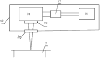
如图1所示,本实用新型所涉及的选区激光熔化快速成型设备的一种具体实施方式包括激光器组1、光学系统3、基板8、基板升降运动机构13、成型缸7、成型缸重量平衡机构15、回收缸6、定量送粉机构2、铺粉装置12和控制系统14。As shown in Figure 1, a specific embodiment of the selective laser melting rapid prototyping equipment involved in the utility model includes a
成型缸7表面及回收缸6的表面为同一平面即加工平面,铺粉装置12可以在加工平面上左右运动。光学系统3位于成型缸7的正上方,定量送粉机构2位于光学系统3的一侧。激光器组1发出的多束激光经由光学系统3聚焦于成型缸7表面。The surface of forming
成型缸7内装有基板8,基板8是成型零件的生长基底,其上方为粉末和待成型零件9,基板8由其下方的升降运动机构13带动在成型缸7内上下运动,成型缸重量平衡机构15位于设备的底部,并作用于升降运动机构13上。The
在上述结构中,可以增设第二回收缸6’、第二送粉机构2’、保护气氛罩5、气体净化系统4、基板调平机构11和加热保温系统10中的至少一个,其中,第二回收缸6’和第二送粉机构2’必须同时增设。保护气氛罩5和气体净化系统4必须同时增设。当上述各部件均同时增设时,其结构如图2所示。In the above structure, at least one of the second recovery cylinder 6', the second powder feeding mechanism 2', the
第二回收缸6’与第一回收缸6分别位于成型缸7的两侧,三者的表面为同一平面即加工平面,铺粉装置12可以在加工平面上左右运动,加工平面及铺粉装置12等所占用的空间由保护气氛罩5所笼罩,保护气氛罩5左右分别由进气口和排气口连通气体净化系统4(图2中为了绘图方便将气体净化系统4画成了左右两部分)。保护气氛罩5的上方是光学系统3、定量送粉机构2、2’,其中光学系统3位于中间,左右两侧各有一个定量送粉机构,激光器组1发出的多束激光经由光学系统3聚焦于成型缸7表面。The second recovery cylinder 6' and the
增设的基板调平机构11安装在基板8上方。The added
增设的加热保温系统10位于在成型缸7内,加热保温系统10为分段式,由基板8与升降运动机构13之间的加热结构和成型缸7内壁的加热结构共同构成。该加热结构可以是电阻丝、加热板、感应加热或者远红外加热等各种加热形式。The added heating and
以图2所示结构为例,以工业控制计算机和运动控制卡为主体的控制系统14控制各机构协调运动。基本工作过程如下:Taking the structure shown in Fig. 2 as an example, the
(1)打开保护气氛罩5,将基板8置于成型缸7内的加热结构上,通过基板调平机构11将基板8调整至水平。将保护气氛罩5密封并开启气体净化系统4,由进气口向罩内充入惰性气体,并保持循环,使罩内气体氛围控制在加工所需的范围内。(1) Open the
(2)将待成型零件的STL文件导入工业控制计算机并获得零件的切片数据,生成每一层的激光加工轨迹。(2) Import the STL file of the part to be formed into the industrial control computer and obtain the slice data of the part, and generate the laser processing trajectory of each layer.
(3)定量送粉器2’将粉末按照设定的量送到成型缸7表面右侧,基板8下降一个切片的高度,铺粉装置12从右向左移动至回收缸6处,粉末即平铺在基板8上,激光器组1发出激光,光学系统3控制聚焦光斑按照加工轨迹在加工平面移动,实现当前层的加工。(3) Quantitative powder feeder 2' sends the powder to the right side of the surface of the
(4)定量送粉器2将粉末按照设定的量送到成型缸7表面左侧,基板8下降一个切片的高度,铺粉装置12从左向右移动至回收缸6’处,在已沉积的金属层上均匀的平铺上一层新的粉末,激光器组1发出激光,光学系统3控制聚焦光斑按照加工轨迹在加工平面移动,实现当前层的加工。(4) The
(5)不断重复步骤(3)、(4),最终实现零件由二维成型向三维成型的扩展,获得实体零件。(5) Steps (3) and (4) are repeated continuously to finally realize the expansion of parts from two-dimensional molding to three-dimensional molding, and obtain solid parts.
(6)在加工过程中,加热保温系统10随着基板8的不断下降分阶段的打开,确保始终只加热位于基板8上方的粉末和零件。同时,每增加一层时,控制系统14根据零件的切片厚度和粉末的松装密度计算出成型缸增加的重量,并控制成型缸重量平衡机构15提供同等重量的实时力进行平衡,使升降运动机构13承受的重量始终保持恒定,保证基板8平稳运动。(6) During the processing, the heating and
下面举例说明各部件的几种具体实现方式。The following examples illustrate several specific implementations of each component.
本实用新型所涉及的选区激光熔化快速成型设备的激光器组由一台或数台乃至数十台激光器组成,激光器可以是中、高功率的CO2激光器、Nd:YAG激光器、光纤激光器和半导体激光器等,其数量由光学系统的设计结构所决定。The laser group of the selective laser melting rapid prototyping equipment involved in the utility model is composed of one or several or even tens of lasers, and the lasers can be medium and high power CO2 lasers, Nd:YAG lasers, fiber lasers and semiconductor lasers etc., the number of which is determined by the design structure of the optical system.
本实用新型所涉及的光学系统是实现选区激光熔化快速成型设备高效制造出精度高、性能优异的大尺寸零件的关键技术之一。本实用新型所涉及的光学系统可以采用固定阵列分布模式、移动平台模式或者上述两者的混合模式。各种模式下的基本组成结构为光学系统单元,如图3所示,每一个光学系统单元包括扩束镜17、XY激光扫描振镜18、f-θ组合透镜19,激光从出光口16发出,依次经过扩束镜17、XY激光扫描振镜18和f-θ组合透镜19聚焦在加工平面上,为防止烟尘、粉尘污染以上提到的光学器件,在f-θ组合透镜19与加工平面之间安装保护镜片20。光学系统单元也可由扩束镜和XYZ三维动态聚焦扫描振镜构成,激光从出光口16发出,依次经过扩束镜17和XYZ三维动态聚焦扫描振镜聚焦在加工平面上。根据采用的模式不同,本实用新型所涉及的光学系统还包括可以使光学系统单元在二维或者三维空间移动的相关机械结构。光学系统单元还可以采用现有技术中其它任意一种能够进行激光束聚集用于激光加工的光学器件。The optical system involved in the utility model is one of the key technologies for realizing the high-precision and excellent-performance large-size parts manufactured by the selective laser melting rapid prototyping equipment efficiently. The optical system involved in the utility model can adopt a fixed array distribution mode, a mobile platform mode or a mixed mode of the above two. The basic composition structure in various modes is an optical system unit, as shown in Figure 3, each optical system unit includes a
图4~图11分别给出了固定阵列分布模式、移动平台模式、混合模式下的光路设计示意图,但本实用新型并不局限于这些示意图所描述的光学系统。不同的光学系统的动作只在每一层的激光扫描过程中存在差别,对于设备其他结构的运动过程不产生影响,在此不再赘述。Figures 4 to 11 respectively show the schematic diagrams of optical path design in the fixed array distribution mode, mobile platform mode, and mixed mode, but the utility model is not limited to the optical systems described in these schematic diagrams. The actions of different optical systems are only different in the laser scanning process of each layer, and have no effect on the movement process of other structures of the device, which will not be repeated here.
根据加工零件尺寸大小不同,固定阵列分布模式可以采用数台或数十台的激光器及对应的光学系统单元按阵列排列构成,可用于任意形状零件的成型。一台激光器可以对应一个光学系统单元,也可以通过分光对应多个光学系统单元。图4给出了固定阵列分布模式光学系统的第一种具体实现方式,若干光学系统单元21按照矩形阵列排列并固定在定位板22上,实际应用时只需将定位板22放置在如图2所示的光学系统所在的位置即可,光学系统单元21即为图3所示结构。光学系统单元21所对应的加工区域规划方法如下:基板被划分为若干相同或不同的区域,相邻区域之间有少量重合的部分,每个光学系统单元的扫场覆盖基板上的一个区域,该区域的大小和形状由光学系统所采用的器件(如XY激光扫描振镜和f-θ组合透镜或者XYZ三维动态聚焦扫描振镜等)决定。计算机将零件三维模型的XY平面分解成若干区域,与基板上划分的区域在形状、大小、位置上一一对应,激光扫描时每一个光学系统单元按照计算机分配的该单元所对应的区域内切片图形数据选区熔化粉末。激光加工时所有光学系统单元同时工作,重叠区域的加工可以选择一个光学系统单元扫描另一个光学系统单元不扫描的形式,也可以选择两个光学系统单元分别扫描的形式或者交替扫描形式,以确保结合部位的加工质量为准。Depending on the size of the processed parts, the fixed array distribution mode can be composed of several or dozens of lasers and corresponding optical system units arranged in an array, which can be used for molding parts of any shape. One laser can correspond to one optical system unit, or can correspond to multiple optical system units through light splitting. Figure 4 shows the first specific implementation of the fixed array distributed mode optical system. Several
图5给出了固定阵列分布模式光学系统的第二种具体实现方式,若干光学系统单元21按照圆周阵列排列并固定在定位板22上,可用于大型圆环状零件的加工。图中每一条圆周点划线表示一个圆周阵列中光学系统单元布置的中心线,自内向外根据光学系统单元所能覆盖的范围层层排列,以确保所有光学系统单元组合后的加工区域覆盖整个零件。光学系统单元21所对应的加工区域规划方法与第一种实现方式相似,区别在于需要根据圆环零件的形状、大小以圆周阵列形式排列各区域。FIG. 5 shows the second specific implementation of the fixed array distributed mode optical system. Several
采用图4和图5两种固定阵列分布模式的光学系统,分别对应加工不同形状的金属零部件,它们的共同优点是扫描过程中所有激光器和光学系统单元同时工作,每一层的选区熔化成型时间取决于扫描时间最长的那一组激光器和光学系统单元,单层加工时间短,加工效率很高。缺点是整个加工区域的覆盖需要很多光学系统单元及对应的激光器,设备搭建的成本较高。Two optical systems with fixed array distribution patterns in Figure 4 and Figure 5 are used to process metal parts of different shapes respectively. Their common advantage is that all lasers and optical system units work at the same time during the scanning process, and the selected area of each layer is melted and formed. The time depends on the group of lasers and optical system units with the longest scanning time. The single-layer processing time is short and the processing efficiency is high. The disadvantage is that the coverage of the entire processing area requires many optical system units and corresponding lasers, and the cost of equipment construction is relatively high.
光学系统单元21可以为矩形、圆周形式或者其它任意形式的阵列排列。The
图6给出了移动平台模式光学系统的第一种具体实现方式,该光学系统采用XY滚珠丝杠搭载光学系统单元。在XY滚珠丝杠移动平台模式光学系统中,光学系统单元21直接安装在由X向丝杠23和Y向丝杠24构成的移动平台上,计算机通过控制XY滚珠丝杠移动平台移动光学系统单元21使其加工区域覆盖整个基板。光学系统单元21的加工区域规划方法如下:由若干形状、大小相同或者不同的区域拼合零件在XY平面的投影图形,相邻区域有少量重合部分,各区域的形状和大小由光学系统所采用的器件决定。在激光扫描加工时,计算机通过控制XY滚珠丝杠移动平台将光学系统单元21按照一定的顺序分别移动到每一个区域的上方,依次完成这些区域内的激光扫描过程。Fig. 6 shows the first specific implementation of the optical system in the mobile platform mode, the optical system uses an XY ball screw to carry the optical system unit. In the XY ball screw moving platform mode optical system, the
图7给出了移动平台模式光学系统的第二种具体实现方式,由圆周环绕移动平台搭载光学系统单元21,加工区域的划分方式参照图5所示的圆周阵列分布模式的光学系统。激光加工时,光学系统单元21在圆形滑轨25上依次移动至每一个区域的上方,完成这些区域内图形的激光扫描过程。FIG. 7 shows the second specific implementation of the optical system in the mobile platform mode. The
此模式借助移动平台扩大了单台激光器和单个光学系统单元所能加工的零件尺寸,使选区激光熔化设备所能成型零件的尺寸不再受光学元器件的限制,但是,每一层的选区激光扫描任务都是由这一台激光器和光学系统单元完成,加工所需时间远远长于固定阵列分布模式,效率非常低。This mode expands the size of parts that can be processed by a single laser and a single optical system unit with the help of a mobile platform, so that the size of parts that can be formed by selective laser melting equipment is no longer limited by optical components. However, the selective laser of each layer The scanning tasks are all completed by this laser and optical system unit, and the time required for processing is much longer than that of the fixed array distribution mode, and the efficiency is very low.
光学系统单元21可以安装在除了XY滚珠丝杠和圆形滑轨以外的任意形式的二维和三维移动平台。The
图8~图11是给出的四种混合模式光学系统的实现方式。图8是混合模式光学系统的第一种实现方式,它采用XY滚珠丝杠搭载矩形阵列模式光学系统26;图9中混合模式光学系统的第二种实现方式,它采用圆周环绕移动平台搭载矩形阵列模式光学系统26。矩形阵列模式光学系统26即如图4所示的矩形阵列模式光学系统,矩形阵列模式光学系统26分别取代图6中XY滚珠丝杠移动平台模式光学系统和图7中圆周环绕移动平台模式光学系统的光学系统单元21,即构成混合模式光学系统的第一种和第二种实现方式。根据矩形阵列模式光学系统26所覆盖的加工区域及移动平台的形状和运动特性拼合零件在XY平面的投影图形,激光扫描加工时,矩形阵列模式光学系统26依次移动至不同的加工区域上方,所有光学系统单元21、21’…同时加工该区域。Fig. 8 to Fig. 11 are the implementation manners of the given four mixed-mode optical systems. Fig. 8 is the first implementation of the mixed-mode optical system, which adopts XY ball screw to carry the rectangular array mode
图10所示的混合模式光学系统的第三种实现方式。它以图6所示的移动平台模式光学系统27为基本组成单元,按照矩形阵列形式安装在定位板22上。各基本组成单元的加工区域的划分方法与混合模式的第一种实现方式相同,并且各基本组成单元的激光扫描加工同时进行。A third implementation of the mixed-mode optical system shown in FIG. 10 . It takes the mobile platform mode
图11给出的混合模式光学系统的第四种实现方式,采用圆周环绕移动平台搭载多个矩形阵列光学系统26,所有矩形阵列光学系统26均匀分散排列,且都可以在移动平台上运动。该模式下的光学系统在加工区域分配上与图9所示光学系统的区域分配相同,每个矩形阵列光学系统26和26’等需要进行若干区域的激光扫描加工,加工过程中各矩形阵列光学系统26和26’等同时扫描、同时移动,完成每一层的激光加工任务。The fourth implementation of the mixed-mode optical system shown in FIG. 11 adopts a mobile platform around the circumference to carry multiple rectangular array
混合模式是固定阵列模式和移动平台模式的综合应用,采用多台激光器和多个光学系统单元同时扫描,加工效率介于上述两种模式之间,并且可以根据零部件的不同形状采用优化算法控制不同光学系统单元或者光学系统单元组成的阵列在移动平台上先后移动的次序和位置,以此进一步提高激光器和光学系统的利用效率,获得最优的效率、成本比。The hybrid mode is a comprehensive application of the fixed array mode and the mobile platform mode. It uses multiple lasers and multiple optical system units to scan simultaneously. The processing efficiency is between the above two modes, and it can be controlled by an optimized algorithm according to the different shapes of the parts. The order and position of different optical system units or arrays composed of optical system units move successively on the mobile platform, so as to further improve the utilization efficiency of lasers and optical systems, and obtain the optimal efficiency and cost ratio.
如图12所示,本实用新型的分段式加热保温系统由两部分组成,一部分为位于成型缸7内壁的电阻丝32,电阻丝32自上而下分成若干段,在零件成型过程中随着基板8的下降依次打开;另一部分固定在基板8的下方,依次为加热板28、隔热用陶瓷纤维板29和具有冷却流道的冷却板30。在零件的成型过程中,根据零件的材料决定是否采用加热保温功能、设定加热保温的温度以及加热保温的时机。分段电阻丝的应用目的在于提高热量的利用效率,隔热板和冷却板则主要用于阻止加热产生的热量向基板升降运动机构和其他功能机构扩散,影响设备工作的稳定性。此加热系统还可以采用感应加热、远红外加热等不同的加热形式,具体方案以获得最高加热效率为准。As shown in Figure 12, the segmented heating and heat preservation system of the present utility model is composed of two parts, one part is the
如图12所示,基板升降运动机构包括活塞31、圆形衔接板33、第一滚珠丝杠35、涡轮蜗杆减速器36和第一电机37。活塞31上端与冷却板30相连,下端与圆形衔接板33相连,滚珠丝杠35一端位于圆形衔接板33的中心位置并与之固定,另一端与涡轮蜗杆减速器36相连,涡轮蜗杆减速器36与第一电机37相连。工作时由第一电机37带动涡轮减速器36转动,从而带动滚珠丝杠35转动,并带动与之相连的圆形衔接板33、活塞31等同步运动,进而使基板8上下运动。As shown in FIG. 12 , the substrate lifting mechanism includes a
基板升降运动机构根据所需载荷的不同还可添加多套电机、涡轮蜗杆减速器结构共同作用于圆形衔接板上;也可以采用齿轮齿条结构替换滚珠丝杠,由电机带动齿轮旋转,齿条上下移动带动固定在其上端的活塞、圆形衔接板及基板等一致上下移动;还可以采用伺服液压传动机构直接作用于基板或加热保温系统下部,带动基板等上下移动。The base plate lifting movement mechanism can also add multiple sets of motors and worm gear reducer structures to act on the circular connecting plate according to the different loads required; the rack and pinion structure can also be used to replace the ball screw, and the motor drives the gear to rotate. The up and down movement of the strip drives the piston, the circular connecting plate and the base plate fixed on its upper end to move up and down in unison; the servo hydraulic transmission mechanism can also be used to directly act on the base plate or the lower part of the heating and heat preservation system to drive the base plate to move up and down.
如图12所示,成型缸重量平衡机构由至少二个液压机构38和钢丝绳、滑轮构成的连接机构34组成,在基板8下降的过程中,各液压机构38通过连接机构34的钢丝绳作用于圆形衔接板33上,提供实时作用力以平衡随着成型缸7内粉末不断积累、零件不断生长所产生的巨大负载,使升降运动机构13承受的重量始终保持恒定。该机构的构成形式不局限于采用钢丝绳和滑轮组成的连接结构,还可以根据设备尺寸的不同采用如图13所示的形式,即液压机构38直接作用在圆形衔接板33上。As shown in Figure 12, the forming cylinder weight balance mechanism is composed of at least two
本设备可以采用单个送粉机构也可以采用两个送粉机构,送粉机构可以为定量或非定量方式,送粉机构的具体结构可以采用现有的各种结构,也可以采用本实例提供的结构。下面说明定量送粉机构的一种具体实施方式的结构。如图14所示,定量送粉机构主要包括贮粉箱41,套筒42、滚筒43、输粉管44和第二电机49等。套筒42水平放置,筒壁上开有进粉槽和出粉槽,进粉槽的位置与贮粉箱41的出口39相对应,出粉槽与输粉管44相连通。滚筒43安装在套筒42内,其外围与套筒42内壁紧密贴合,并沿圆周开有至少一个贮粉凹槽40,第二电机49带动滚筒43在套筒42内旋转。需要注意的是:凹槽40的横截面、套筒42的进粉槽和出粉槽的横截面、出口39以及输粉管44的管口五者形状相匹配,最好均为细窄的长方形。送粉时,第二电机49带动滚筒43旋转,贮粉凹槽40的一个凹槽对准出口39时粉末进入贮粉凹槽40,同时与之相对的另一个凹槽则对准输粉管44的上管口,其内粉末随输粉管44下落,滚筒43每转动一定的角度,即可送出一定量的粉末。This equipment can adopt a single powder feeding mechanism or two powder feeding mechanisms. The powder feeding mechanism can be quantitative or non-quantitative. The specific structure of the powder feeding mechanism can adopt various existing structures or the one provided in this example. structure. The structure of a specific embodiment of the quantitative powder feeding mechanism is described below. As shown in Figure 14, the quantitative powder feeding mechanism mainly includes a
根据零部件制造的要求不同,送粉机构可以为开放式或封闭式结构。当零件需要在保护气氛中制造时,必须采用封闭式的送粉机构,这种封闭式的送粉机构是指贮粉箱41为封闭式,仅通过输粉管44对外送粉。According to different parts manufacturing requirements, the powder feeding mechanism can be an open or closed structure. When the parts need to be manufactured in a protective atmosphere, a closed powder feeding mechanism must be used. This closed powder feeding mechanism means that the
本实用新型采用的定量送粉机构除了采用前述旋转式定量送粉机构,还可以采用平移式定量送粉机构。如图18所示,平移式定量送粉机构包括贮粉箱41、支架60、进粉槽59、出粉槽61、送粉板62、运动机构63和输粉管44。支架60上部和下部分别开有水平错开的进粉槽59和出粉槽61,进粉槽59的位置与贮粉箱41的出口39相对应,出粉槽61与输粉管44相连通。开有贮粉孔64的送粉板62水平安装在支架60中,送粉板62的右端连接运动机构63,运动机构63可以由电机和丝杠组合,也可以由高压气流和继电器组合,或者是其它能够推动送粉板62左右移动的结构形式。与旋转式定量送粉机构类似,进粉槽59、出粉槽61、贮粉孔64的横截面、出口39以及输粉管44的管口五者形状相匹配,最好均为细窄的长方形。送粉时,运动机构63带动送粉板62运动使贮粉孔64对准进粉槽59,贮粉箱41中的粉末依靠重力进入贮粉孔64,送粉板左移使贮粉孔64对准出粉槽61,贮粉孔64中的粉末沿输粉管44自由下落,即可送出一定量的粉末,通过左右移动的次数即可实现定量送粉。The quantitative powder feeding mechanism adopted in the utility model can also adopt a translational quantitative powder feeding mechanism in addition to the aforementioned rotary type quantitative powder feeding mechanism. As shown in FIG. 18 , the translational quantitative powder feeding mechanism includes a
使用两个送粉机构时,二者结构可以相同也可以不同。When two powder feeding mechanisms are used, the structures of the two can be the same or different.
如图22所示,成型缸重量平衡机构还可以由至少二套定量送粉组件构成,各定量送粉组件均包括第三定量送粉机构69,盛粉箱70、定向导轨71和钢丝绳、滑轮构成的连接结构34组成。定向导轨71垂直安装在设备底部,盛粉箱70活动安装在定向导轨71上,可以沿定向导轨71上下移动,第三定量送粉机构69的出粉口分别位于盛粉箱70的上方,在基板8下降的过程中,第三定量送粉机构69不断的向盛粉箱70送入粉末,送入粉末的重量与成型缸7内粉末积累和零件生长所产生的重量相同,保证基板8精确、稳定的上下运动。第三定量送粉机构69可以采用与第一、第二定量送粉机构相同结构,也可以采用当前应用较广的皮带轮送粉结构和熔覆用送粉器结构。As shown in Figure 22, the weight balance mechanism of the forming cylinder can also be composed of at least two sets of quantitative powder feeding assemblies, each quantitative powder feeding assembly includes a third quantitative
如图14所示,铺粉装置包括T型横梁45、位于横梁45两侧的导粉管46、刮板48、压块47和传动机构。导粉管46的上管口与输粉管44的下管口齐高,确保粉末在自由下落过程中不会对加工腔体造成污染。刮板48的材料可以是陶瓷、硬质金属合金或有机材质等,由压块47紧固在T型横梁45下端的凹槽中,刮板48下表面为光滑平面并紧贴加工平面,T型横梁45位于基板8上方。送粉前,T型横梁45在传动机构的带动下移动至右侧定量送粉机构的下方,并使左侧导粉管46的上管口与输粉管44管口对齐,粉末完全下落后,T型横梁水平移动至左侧回收缸,完成当前层的铺粉动作,同理适用于与之对称的左侧结构的铺粉过程,由此实现本设备的双向铺粉功能,大幅提高铺粉效率。T型横梁45的传动机构可采用电机带动的滚珠丝杠传动机构,也可采用电机带动的皮带轮传动机构,或者其他类型的直线传动机构。As shown in FIG. 14 , the powder spreading device includes a T-shaped
在精度要求不高的条件下,铺粉装置也可以采用滚筒式铺粉机构。Under the condition that the accuracy requirement is not high, the powder spreading device can also adopt the roller powder spreading mechanism.
如图15所示,基板调平机构包括导轨52、调平支架54。导轨52沿成型缸Y轴方向安装在T型横梁45上,并平行于加工平面,调平支架54安装在导轨52上,该支架水平部分前端开有上下贯穿圆孔55,用于装夹千分表,另有垂直圆孔的螺钉53紧固。为了达到更好的调平效果,基板8通过定位螺钉50与调平螺钉51安装在加热板28上,定位螺钉50与调平螺钉51均呈均匀分布,不局限于图15所示的三组螺钉。具体调平方法如下:以加工平面为基准,通过T型横梁45带动安装有千分表的调平支架54沿X轴方向左右移动,同时调平支架54可以沿Y向导轨52前后移动,从而显示基板8各位置的高度数值,并通过调整调平螺钉51的高低位置使基板8上表面与加工平面重合。As shown in FIG. 15 , the substrate leveling mechanism includes a guide rail 52 and a leveling bracket 54 . The guide rail 52 is installed on the T-shaped
由于较大尺寸的基板重量很大,采用定位螺钉和调平螺钉进行调平在调平过程中准确性较差或受到人体力量限制,较难达到使用要求。为此本实用新型还可以采用另外一种机构取代定位螺钉和调平螺钉,该机构包括位于冷却板30和活塞31之间的固定杆68、支撑架66、66’、第三、第四电机67、67’、第二、第三滚珠丝杠65、65’,如图19所示,其中固定杆68的一端固定在活塞31上,另一端直接连接在冷却板30下面。第一、第二支撑架66、66’固定在活塞31上,第二滚珠丝杠65垂直安装在第一支撑架66上,其上端与冷却板30固定,下端与第三电机67相连。同理第二支撑架66’、第四电机67’、第三滚珠丝杠65’以相同的结构连接,即第三滚珠丝杠65’垂直安装在第二支撑架66’上,上端与冷却板30固定,下端与第四电机67’相连。为了便于调节,固定杆68与第一、第二支撑架66、66’连接所形成的三角形最好为等边三角形。调平过程中依靠第三、第四电机67、67’带动丝杠旋转,从而带动冷却板30运动,以三点确定一个平面的原理实现并保持基板8水平。Due to the heavy weight of the large-sized substrate, it is difficult to meet the use requirements due to poor accuracy or limited by human strength during the leveling process using positioning screws and leveling screws. For this reason, the utility model can also adopt another kind of mechanism to replace the positioning screw and the leveling screw. 67 , 67 ′, second and
保护气氛罩在对加工腔体内进行密封的同时必须保证足够的通光面积以确保激光束经振镜偏转后可以完全聚焦在加工平面,因此须在保护气氛罩盖板上增设有保护镜片。图16、17分别为不同保护镜片类型的保护气氛罩的俯视图,其中图16所示为阵列分布的多个保护镜片57嵌于保护气氛罩盖板56上,主要与阵列分布模式的光学系统搭配,每一个保护镜片对应阵列分布模式中一个光学系统单元。图17所示为单一大型保护镜片58嵌于保护气氛罩盖板56上,主要与移动平台模式、混合模式的光学系统搭配。前者对于保护镜片的材料及制作要求不高,可随时更换出现故障的保护镜片,经济性较好;后者虽然成本较高,但可以满足移动平台模式和混合模式下光学系统单元随机定位的使用要求,在任意位置均可实现激光束的完全穿透。While the protective atmosphere cover seals the processing chamber, it must ensure sufficient light-transmitting area to ensure that the laser beam can be completely focused on the processing plane after being deflected by the galvanometer. Therefore, a protective lens must be added on the cover plate of the protective atmosphere cover. Figures 16 and 17 are top views of protective atmosphere covers with different types of protective lenses, in which Figure 16 shows that a plurality of
气体净化系统通过进气口和排气口与保护气氛罩构成封闭循环,确保保护气氛罩内的水、氧含量达到使用要求。进气口与排气口均设置有粉尘过滤装置,防止加工过程中产生的微、纳米粉尘污染内外环境。The gas purification system forms a closed cycle through the air inlet and exhaust port and the protective atmosphere hood to ensure that the water and oxygen content in the protective atmosphere hood meet the use requirements. Both the air inlet and the exhaust port are equipped with dust filter devices to prevent the micro and nano dust generated during the processing from polluting the internal and external environment.
大型保护镜片的加工制造难度较大,为了更好的实现移动平台模式光学系统和混合模式光学系统也可将光学系统3整体置入气体保护罩5内。具体布置方法如图20所示,光学系统3固定在气体保护罩5的盖板下方,其他部件和结构位置基本不变。如图21所示,采用此结构,需要对每一个开放式的光学系统单元单独加装密封罩69,保护光学器件免受腔体内粉尘和烟尘的污染,光学系统单元的排列布置及扫描方式与外置光学系统一致。The processing and manufacturing of the large protective lens is relatively difficult. In order to better realize the mobile platform mode optical system and the hybrid mode optical system, the
本实用新型不仅局限于上述具体实施方式,本领域一般技术人员根据本实用新型公开的内容,可以采用其它多种具体实施方式实施本实用新型,因此,凡是采用本实用新型的设计结构和思路,做一些简单的变化或更改的设计,都落入本实用新型保护的范围。The utility model is not limited to the above-mentioned specific implementation methods, and those skilled in the art can implement the utility model by adopting other various specific implementation modes according to the disclosed content of the utility model. Do some simple changes or modified designs, all fall into the protection scope of the present utility model.
Claims (18)
Priority Applications (1)
| Application Number | Priority Date | Filing Date | Title |
|---|---|---|---|
| CN2011202516312U CN202291409U (en) | 2011-07-15 | 2011-07-15 | Selective laser melting rapid molding equipment for directly fabricating large-sized parts |
Applications Claiming Priority (1)
| Application Number | Priority Date | Filing Date | Title |
|---|---|---|---|
| CN2011202516312U CN202291409U (en) | 2011-07-15 | 2011-07-15 | Selective laser melting rapid molding equipment for directly fabricating large-sized parts |
Publications (1)
| Publication Number | Publication Date |
|---|---|
| CN202291409U true CN202291409U (en) | 2012-07-04 |
Family
ID=46360389
Family Applications (1)
| Application Number | Title | Priority Date | Filing Date |
|---|---|---|---|
| CN2011202516312U Expired - Lifetime CN202291409U (en) | 2011-07-15 | 2011-07-15 | Selective laser melting rapid molding equipment for directly fabricating large-sized parts |
Country Status (1)
| Country | Link |
|---|---|
| CN (1) | CN202291409U (en) |
Cited By (22)
| Publication number | Priority date | Publication date | Assignee | Title |
|---|---|---|---|---|
| CN102266942A (en) * | 2011-07-15 | 2011-12-07 | 华中科技大学 | Selective laser melting rapid forming device for directly manufacturing large-size parts |
| CN103071795A (en) * | 2013-01-23 | 2013-05-01 | 西安铂力特激光成形技术有限公司 | Mobile galvanometer selective laser melting (SLM) forming device |
| CN103071798A (en) * | 2013-01-23 | 2013-05-01 | 西安铂力特激光成形技术有限公司 | Linear guide rail type SLM (Selective Laser Melting) molding equipment |
| CN103658647A (en) * | 2013-12-10 | 2014-03-26 | 华南理工大学 | SLM device based on four lasers and two stations and machining method |
| CN104001915A (en) * | 2014-05-22 | 2014-08-27 | 华中科技大学 | Equipment for manufacturing large-size metal part in high energy beam additive manufacturing mode and control method of equipment |
| CN104416158A (en) * | 2013-09-09 | 2015-03-18 | 通用电气公司 | Three-dimensional printing process, swirling device, and thermal management process |
| CN104972121A (en) * | 2014-04-04 | 2015-10-14 | 株式会社松浦机械制作所 | Three-dimensional molding equipment |
| CN105132912A (en) * | 2015-09-06 | 2015-12-09 | 苏州西帝摩三维打印科技有限公司 | External mobile scanning system for selective laser melting |
| CN105562689A (en) * | 2015-11-26 | 2016-05-11 | 阳江市五金刀剪产业技术研究院 | Bothway powder paving powder based additive material manufacturing device and powder paving method thereof |
| CN105855544A (en) * | 2016-04-29 | 2016-08-17 | 西安交通大学 | Electromagnetically-induced three-dimensional heating system for selective laser melting |
| CN105855543A (en) * | 2015-01-24 | 2016-08-17 | 长沙嘉程机械制造有限公司 | Plotter type selective laser melting additive manufacturing machine |
| CN106392067A (en) * | 2016-03-06 | 2017-02-15 | 武汉理工大学 | Selective laser fusing equipment based on wet-process powder spreading and printing process thereof |
| CN106903313A (en) * | 2017-04-12 | 2017-06-30 | 窦鹤鸿 | Selective laser melting appartus and 3D printer |
| CN107009616A (en) * | 2017-05-25 | 2017-08-04 | 安徽恒利增材制造科技有限公司 | A powder feeding mechanism of a double feeding cylinder 3D printer |
| CN107042308A (en) * | 2017-04-27 | 2017-08-15 | 北京工业大学 | A kind of antifouling powder device for powdering formula constituency fusion apparatus moulding cylinder |
| CN108326300A (en) * | 2018-01-25 | 2018-07-27 | 海宁市锦新轴承有限公司 | A kind of car model processing unit (plant) |
| CN108463300A (en) * | 2015-11-16 | 2018-08-28 | 瑞尼斯豪公司 | Module for increasing material manufacturing device and method |
| CN108555299A (en) * | 2018-06-20 | 2018-09-21 | 华中科技大学 | A kind of power spreading device and its system and method suitable for the advanced manufacture of laser |
| CN109434107A (en) * | 2018-12-06 | 2019-03-08 | 华中科技大学 | A kind of multipotency beam high efficiency increasing material manufacturing method |
| JP2020015949A (en) * | 2018-07-25 | 2020-01-30 | パナソニックIpマネジメント株式会社 | Method for manufacturing three-dimensional molded article |
| CN112059179A (en) * | 2020-08-04 | 2020-12-11 | 北京航空航天大学 | Laser additive manufacturing equipment and method for manufacturing large metal component |
| US11040414B2 (en) | 2008-09-05 | 2021-06-22 | Renishaw Plc | Additive manufacturing apparatus with a chamber and a removably-mountable optical module; method of preparing a laser processing apparatus with such removably-mountable optical module |
-
2011
- 2011-07-15 CN CN2011202516312U patent/CN202291409U/en not_active Expired - Lifetime
Cited By (35)
| Publication number | Priority date | Publication date | Assignee | Title |
|---|---|---|---|---|
| US11040414B2 (en) | 2008-09-05 | 2021-06-22 | Renishaw Plc | Additive manufacturing apparatus with a chamber and a removably-mountable optical module; method of preparing a laser processing apparatus with such removably-mountable optical module |
| CN102266942A (en) * | 2011-07-15 | 2011-12-07 | 华中科技大学 | Selective laser melting rapid forming device for directly manufacturing large-size parts |
| CN103071795B (en) * | 2013-01-23 | 2016-03-02 | 西安铂力特激光成形技术有限公司 | Mobile galvanometer selective laser melting SLM former |
| CN103071798B (en) * | 2013-01-23 | 2015-11-18 | 西安铂力特激光成形技术有限公司 | Linear guide rail type selective laser melting SLM former |
| CN103071795A (en) * | 2013-01-23 | 2013-05-01 | 西安铂力特激光成形技术有限公司 | Mobile galvanometer selective laser melting (SLM) forming device |
| CN103071798A (en) * | 2013-01-23 | 2013-05-01 | 西安铂力特激光成形技术有限公司 | Linear guide rail type SLM (Selective Laser Melting) molding equipment |
| CN104416158B (en) * | 2013-09-09 | 2018-09-18 | 通用电气公司 | 3 D-printing technique, rotation apparatus and heat management technique |
| CN104416158A (en) * | 2013-09-09 | 2015-03-18 | 通用电气公司 | Three-dimensional printing process, swirling device, and thermal management process |
| CN103658647B (en) * | 2013-12-10 | 2015-10-28 | 华南理工大学 | Based on selective laser fusing SLM equipment and the processing method of four laser doubles |
| CN103658647A (en) * | 2013-12-10 | 2014-03-26 | 华南理工大学 | SLM device based on four lasers and two stations and machining method |
| CN104972121B (en) * | 2014-04-04 | 2019-06-21 | 株式会社松浦机械制作所 | Three-dimensional moulding device |
| CN104972121A (en) * | 2014-04-04 | 2015-10-14 | 株式会社松浦机械制作所 | Three-dimensional molding equipment |
| CN104001915B (en) * | 2014-05-22 | 2016-07-27 | 上海电气(集团)总公司 | A kind of high energy beam increases material and manufactures equipment and the control method thereof of large scale metallic element |
| CN104001915A (en) * | 2014-05-22 | 2014-08-27 | 华中科技大学 | Equipment for manufacturing large-size metal part in high energy beam additive manufacturing mode and control method of equipment |
| CN105855543A (en) * | 2015-01-24 | 2016-08-17 | 长沙嘉程机械制造有限公司 | Plotter type selective laser melting additive manufacturing machine |
| CN105132912A (en) * | 2015-09-06 | 2015-12-09 | 苏州西帝摩三维打印科技有限公司 | External mobile scanning system for selective laser melting |
| CN105132912B (en) * | 2015-09-06 | 2018-04-20 | 苏州西帝摩三维打印科技有限公司 | External motion scan system for selective laser melting |
| CN108463300A (en) * | 2015-11-16 | 2018-08-28 | 瑞尼斯豪公司 | Module for increasing material manufacturing device and method |
| US11358224B2 (en) | 2015-11-16 | 2022-06-14 | Renishaw Plc | Module for additive manufacturing apparatus and method |
| CN105562689A (en) * | 2015-11-26 | 2016-05-11 | 阳江市五金刀剪产业技术研究院 | Bothway powder paving powder based additive material manufacturing device and powder paving method thereof |
| CN106392067B (en) * | 2016-03-06 | 2019-01-22 | 武汉理工大学 | Selective laser melting equipment and printing process based on wet powder coating |
| CN106392067A (en) * | 2016-03-06 | 2017-02-15 | 武汉理工大学 | Selective laser fusing equipment based on wet-process powder spreading and printing process thereof |
| CN105855544A (en) * | 2016-04-29 | 2016-08-17 | 西安交通大学 | Electromagnetically-induced three-dimensional heating system for selective laser melting |
| CN106903313A (en) * | 2017-04-12 | 2017-06-30 | 窦鹤鸿 | Selective laser melting appartus and 3D printer |
| CN106903313B (en) * | 2017-04-12 | 2020-01-31 | 窦鹤鸿 | Selective laser melting device and 3D printer |
| CN107042308A (en) * | 2017-04-27 | 2017-08-15 | 北京工业大学 | A kind of antifouling powder device for powdering formula constituency fusion apparatus moulding cylinder |
| CN107009616A (en) * | 2017-05-25 | 2017-08-04 | 安徽恒利增材制造科技有限公司 | A powder feeding mechanism of a double feeding cylinder 3D printer |
| CN108326300A (en) * | 2018-01-25 | 2018-07-27 | 海宁市锦新轴承有限公司 | A kind of car model processing unit (plant) |
| CN108555299A (en) * | 2018-06-20 | 2018-09-21 | 华中科技大学 | A kind of power spreading device and its system and method suitable for the advanced manufacture of laser |
| CN108555299B (en) * | 2018-06-20 | 2024-03-19 | 华中科技大学 | A powder spreading device suitable for laser advanced manufacturing and its system and method |
| JP2020015949A (en) * | 2018-07-25 | 2020-01-30 | パナソニックIpマネジメント株式会社 | Method for manufacturing three-dimensional molded article |
| JP7117584B2 (en) | 2018-07-25 | 2022-08-15 | パナソニックIpマネジメント株式会社 | Method for manufacturing three-dimensional shaped article |
| CN109434107A (en) * | 2018-12-06 | 2019-03-08 | 华中科技大学 | A kind of multipotency beam high efficiency increasing material manufacturing method |
| CN112059179A (en) * | 2020-08-04 | 2020-12-11 | 北京航空航天大学 | Laser additive manufacturing equipment and method for manufacturing large metal component |
| CN112059179B (en) * | 2020-08-04 | 2021-11-02 | 北京航空航天大学 | Laser additive manufacturing equipment and method for the manufacture of large metal components |
Similar Documents
| Publication | Publication Date | Title |
|---|---|---|
| CN202291409U (en) | Selective laser melting rapid molding equipment for directly fabricating large-sized parts | |
| CN102266942B (en) | Selective laser melting rapid forming device for directly manufacturing large-size parts | |
| CN104668563B (en) | A kind of high energy beam increasing material manufacturing method and apparatus with high powder stock utilization rate | |
| CN104001915B (en) | A kind of high energy beam increases material and manufactures equipment and the control method thereof of large scale metallic element | |
| WO2021017129A1 (en) | Additive fabrication device and forming method | |
| CN203843168U (en) | Equipment for high-energy-beam additive manufacturing large-size metal parts | |
| CN103495729B (en) | The laser solid forming method of large scale titanium aluminium base alloy | |
| CN103726049B (en) | A kind of laser gain material manufacture method and equipment of metal parts | |
| CN105039970B (en) | A kind of replaceable powder cylinder double light beam laser selective melting former | |
| EP3181272A1 (en) | Synchronous powder-feeding space laser machining and three-dimensional forming method and device | |
| CN203807559U (en) | Laser additive manufacturing equipment of metal components | |
| CN109332697B (en) | A selective laser melting additive manufacturing equipment | |
| CN113172242B (en) | A kind of real-time monitoring device and realization method of selective laser melting forming | |
| CN109434109B (en) | Selective laser melting forming method based on dynamic powder cylinder | |
| RU2674588C2 (en) | Method for additive welding and melting manufacture of three-dimensional products and installation for its implementation | |
| CN105817625A (en) | Composite forming device of molten coating added and decreased materials | |
| CN103962557A (en) | Separable selective rapid forming device | |
| CN204486781U (en) | A kind of high energy beam increases material manufacturing installation | |
| CN210305757U (en) | An Additive Manufacturing Device Based on Dynamic Forming Cylinder | |
| CN104647762A (en) | Cutting processing type 3D (three-dimensional) industrial printing device and printing method | |
| CN105880590A (en) | Additive manufacturing system capable of achieving continuous formation | |
| CN105922574B (en) | A kind of plasma cladding manufacture 3D printing device and method | |
| CN106624826A (en) | Micro-plasma 3D printing and milling combined processing device and method | |
| CN102632336B (en) | Switching macro micro laser high-speed cutting machine tool | |
| CN105922566B (en) | A kind of plasma cladding directly manufactures 3D printing device and method |
Legal Events
| Date | Code | Title | Description |
|---|---|---|---|
| C14 | Grant of patent or utility model | ||
| GR01 | Patent grant | ||
| AV01 | Patent right actively abandoned |
Granted publication date: 20120704 Effective date of abandoning: 20130605 |
|
| AV01 | Patent right actively abandoned |
Granted publication date: 20120704 Effective date of abandoning: 20130605 |
|
| RGAV | Abandon patent right to avoid regrant |