CN1910509A - Liquid crystal display element - Google Patents
Liquid crystal display element Download PDFInfo
- Publication number
- CN1910509A CN1910509A CNA2005800029865A CN200580002986A CN1910509A CN 1910509 A CN1910509 A CN 1910509A CN A2005800029865 A CNA2005800029865 A CN A2005800029865A CN 200580002986 A CN200580002986 A CN 200580002986A CN 1910509 A CN1910509 A CN 1910509A
- Authority
- CN
- China
- Prior art keywords
- liquid crystal
- crystal display
- display element
- photo
- alignment
- Prior art date
- Legal status (The legal status is an assumption and is not a legal conclusion. Google has not performed a legal analysis and makes no representation as to the accuracy of the status listed.)
- Granted
Links
Classifications
-
- G—PHYSICS
- G02—OPTICS
- G02F—OPTICAL DEVICES OR ARRANGEMENTS FOR THE CONTROL OF LIGHT BY MODIFICATION OF THE OPTICAL PROPERTIES OF THE MEDIA OF THE ELEMENTS INVOLVED THEREIN; NON-LINEAR OPTICS; FREQUENCY-CHANGING OF LIGHT; OPTICAL LOGIC ELEMENTS; OPTICAL ANALOGUE/DIGITAL CONVERTERS
- G02F1/00—Devices or arrangements for the control of the intensity, colour, phase, polarisation or direction of light arriving from an independent light source, e.g. switching, gating or modulating; Non-linear optics
- G02F1/01—Devices or arrangements for the control of the intensity, colour, phase, polarisation or direction of light arriving from an independent light source, e.g. switching, gating or modulating; Non-linear optics for the control of the intensity, phase, polarisation or colour
- G02F1/13—Devices or arrangements for the control of the intensity, colour, phase, polarisation or direction of light arriving from an independent light source, e.g. switching, gating or modulating; Non-linear optics for the control of the intensity, phase, polarisation or colour based on liquid crystals, e.g. single liquid crystal display cells
- G02F1/133—Constructional arrangements; Operation of liquid crystal cells; Circuit arrangements
- G02F1/1333—Constructional arrangements; Manufacturing methods
- G02F1/1337—Surface-induced orientation of the liquid crystal molecules, e.g. by alignment layers
- G02F1/13378—Surface-induced orientation of the liquid crystal molecules, e.g. by alignment layers by treatment of the surface, e.g. embossing, rubbing or light irradiation
- G02F1/133788—Surface-induced orientation of the liquid crystal molecules, e.g. by alignment layers by treatment of the surface, e.g. embossing, rubbing or light irradiation by light irradiation, e.g. linearly polarised light photo-polymerisation
-
- G—PHYSICS
- G02—OPTICS
- G02F—OPTICAL DEVICES OR ARRANGEMENTS FOR THE CONTROL OF LIGHT BY MODIFICATION OF THE OPTICAL PROPERTIES OF THE MEDIA OF THE ELEMENTS INVOLVED THEREIN; NON-LINEAR OPTICS; FREQUENCY-CHANGING OF LIGHT; OPTICAL LOGIC ELEMENTS; OPTICAL ANALOGUE/DIGITAL CONVERTERS
- G02F1/00—Devices or arrangements for the control of the intensity, colour, phase, polarisation or direction of light arriving from an independent light source, e.g. switching, gating or modulating; Non-linear optics
- G02F1/01—Devices or arrangements for the control of the intensity, colour, phase, polarisation or direction of light arriving from an independent light source, e.g. switching, gating or modulating; Non-linear optics for the control of the intensity, phase, polarisation or colour
- G02F1/13—Devices or arrangements for the control of the intensity, colour, phase, polarisation or direction of light arriving from an independent light source, e.g. switching, gating or modulating; Non-linear optics for the control of the intensity, phase, polarisation or colour based on liquid crystals, e.g. single liquid crystal display cells
- G02F1/133—Constructional arrangements; Operation of liquid crystal cells; Circuit arrangements
- G02F1/1333—Constructional arrangements; Manufacturing methods
- G02F1/1337—Surface-induced orientation of the liquid crystal molecules, e.g. by alignment layers
-
- C—CHEMISTRY; METALLURGY
- C09—DYES; PAINTS; POLISHES; NATURAL RESINS; ADHESIVES; COMPOSITIONS NOT OTHERWISE PROVIDED FOR; APPLICATIONS OF MATERIALS NOT OTHERWISE PROVIDED FOR
- C09K—MATERIALS FOR MISCELLANEOUS APPLICATIONS, NOT PROVIDED FOR ELSEWHERE
- C09K19/00—Liquid crystal materials
- C09K19/52—Liquid crystal materials characterised by components which are not liquid crystals, e.g. additives with special physical aspect: solvents, solid particles
- C09K19/54—Additives having no specific mesophase characterised by their chemical composition
- C09K19/56—Aligning agents
-
- G—PHYSICS
- G02—OPTICS
- G02F—OPTICAL DEVICES OR ARRANGEMENTS FOR THE CONTROL OF LIGHT BY MODIFICATION OF THE OPTICAL PROPERTIES OF THE MEDIA OF THE ELEMENTS INVOLVED THEREIN; NON-LINEAR OPTICS; FREQUENCY-CHANGING OF LIGHT; OPTICAL LOGIC ELEMENTS; OPTICAL ANALOGUE/DIGITAL CONVERTERS
- G02F1/00—Devices or arrangements for the control of the intensity, colour, phase, polarisation or direction of light arriving from an independent light source, e.g. switching, gating or modulating; Non-linear optics
- G02F1/01—Devices or arrangements for the control of the intensity, colour, phase, polarisation or direction of light arriving from an independent light source, e.g. switching, gating or modulating; Non-linear optics for the control of the intensity, phase, polarisation or colour
- G02F1/13—Devices or arrangements for the control of the intensity, colour, phase, polarisation or direction of light arriving from an independent light source, e.g. switching, gating or modulating; Non-linear optics for the control of the intensity, phase, polarisation or colour based on liquid crystals, e.g. single liquid crystal display cells
- G02F1/133—Constructional arrangements; Operation of liquid crystal cells; Circuit arrangements
-
- G—PHYSICS
- G02—OPTICS
- G02F—OPTICAL DEVICES OR ARRANGEMENTS FOR THE CONTROL OF LIGHT BY MODIFICATION OF THE OPTICAL PROPERTIES OF THE MEDIA OF THE ELEMENTS INVOLVED THEREIN; NON-LINEAR OPTICS; FREQUENCY-CHANGING OF LIGHT; OPTICAL LOGIC ELEMENTS; OPTICAL ANALOGUE/DIGITAL CONVERTERS
- G02F1/00—Devices or arrangements for the control of the intensity, colour, phase, polarisation or direction of light arriving from an independent light source, e.g. switching, gating or modulating; Non-linear optics
- G02F1/01—Devices or arrangements for the control of the intensity, colour, phase, polarisation or direction of light arriving from an independent light source, e.g. switching, gating or modulating; Non-linear optics for the control of the intensity, phase, polarisation or colour
- G02F1/13—Devices or arrangements for the control of the intensity, colour, phase, polarisation or direction of light arriving from an independent light source, e.g. switching, gating or modulating; Non-linear optics for the control of the intensity, phase, polarisation or colour based on liquid crystals, e.g. single liquid crystal display cells
- G02F1/137—Devices or arrangements for the control of the intensity, colour, phase, polarisation or direction of light arriving from an independent light source, e.g. switching, gating or modulating; Non-linear optics for the control of the intensity, phase, polarisation or colour based on liquid crystals, e.g. single liquid crystal display cells characterised by the electro-optical or magneto-optical effect, e.g. field-induced phase transition, orientation effect, guest-host interaction or dynamic scattering
- G02F1/139—Devices or arrangements for the control of the intensity, colour, phase, polarisation or direction of light arriving from an independent light source, e.g. switching, gating or modulating; Non-linear optics for the control of the intensity, phase, polarisation or colour based on liquid crystals, e.g. single liquid crystal display cells characterised by the electro-optical or magneto-optical effect, e.g. field-induced phase transition, orientation effect, guest-host interaction or dynamic scattering based on orientation effects in which the liquid crystal remains transparent
- G02F1/141—Devices or arrangements for the control of the intensity, colour, phase, polarisation or direction of light arriving from an independent light source, e.g. switching, gating or modulating; Non-linear optics for the control of the intensity, phase, polarisation or colour based on liquid crystals, e.g. single liquid crystal display cells characterised by the electro-optical or magneto-optical effect, e.g. field-induced phase transition, orientation effect, guest-host interaction or dynamic scattering based on orientation effects in which the liquid crystal remains transparent using ferroelectric liquid crystals
-
- C—CHEMISTRY; METALLURGY
- C09—DYES; PAINTS; POLISHES; NATURAL RESINS; ADHESIVES; COMPOSITIONS NOT OTHERWISE PROVIDED FOR; APPLICATIONS OF MATERIALS NOT OTHERWISE PROVIDED FOR
- C09K—MATERIALS FOR MISCELLANEOUS APPLICATIONS, NOT PROVIDED FOR ELSEWHERE
- C09K2323/00—Functional layers of liquid crystal optical display excluding electroactive liquid crystal layer characterised by chemical composition
- C09K2323/02—Alignment layer characterised by chemical composition
-
- G—PHYSICS
- G02—OPTICS
- G02F—OPTICAL DEVICES OR ARRANGEMENTS FOR THE CONTROL OF LIGHT BY MODIFICATION OF THE OPTICAL PROPERTIES OF THE MEDIA OF THE ELEMENTS INVOLVED THEREIN; NON-LINEAR OPTICS; FREQUENCY-CHANGING OF LIGHT; OPTICAL LOGIC ELEMENTS; OPTICAL ANALOGUE/DIGITAL CONVERTERS
- G02F1/00—Devices or arrangements for the control of the intensity, colour, phase, polarisation or direction of light arriving from an independent light source, e.g. switching, gating or modulating; Non-linear optics
- G02F1/01—Devices or arrangements for the control of the intensity, colour, phase, polarisation or direction of light arriving from an independent light source, e.g. switching, gating or modulating; Non-linear optics for the control of the intensity, phase, polarisation or colour
- G02F1/13—Devices or arrangements for the control of the intensity, colour, phase, polarisation or direction of light arriving from an independent light source, e.g. switching, gating or modulating; Non-linear optics for the control of the intensity, phase, polarisation or colour based on liquid crystals, e.g. single liquid crystal display cells
- G02F1/133—Constructional arrangements; Operation of liquid crystal cells; Circuit arrangements
- G02F1/1333—Constructional arrangements; Manufacturing methods
- G02F1/1337—Surface-induced orientation of the liquid crystal molecules, e.g. by alignment layers
- G02F1/133773—Surface-induced orientation of the liquid crystal molecules, e.g. by alignment layers the alignment material or treatment being different for the two opposite substrates
Landscapes
- Physics & Mathematics (AREA)
- Nonlinear Science (AREA)
- Chemical & Material Sciences (AREA)
- Crystallography & Structural Chemistry (AREA)
- General Physics & Mathematics (AREA)
- Optics & Photonics (AREA)
- Mathematical Physics (AREA)
- Spectroscopy & Molecular Physics (AREA)
- Liquid Crystal (AREA)
- Engineering & Computer Science (AREA)
- Materials Engineering (AREA)
- Organic Chemistry (AREA)
Abstract
Description
技术领域technical field
本发明涉及一种使用了强介电性液晶的液晶显示元件,更具体来说,涉及使用光取向膜控制了强介电性液晶的取向的液晶显示元件。The present invention relates to a liquid crystal display element using a ferroelectric liquid crystal, and more specifically, to a liquid crystal display element in which orientation of a ferroelectric liquid crystal is controlled using a photo-alignment film.
背景技术Background technique
液晶显示元件由于其薄形、消耗电能低等特征,因而从大型显示器到携带信息终端,得到广泛的应用,对于其开发正在积极地进行之中。迄今为止,液晶显示元件已经开发出并实用化了TN方式、STN的多元驱动、在TN中使用了薄层晶体管(TFT)的有源矩阵驱动等,然而它们由于使用向列相液晶,因此液晶材料的响应速度慢,为数ms~数十ms,无法充分地适应动画显示。Liquid crystal display elements are widely used from large displays to portable information terminals due to their thin shape and low power consumption, and their development is actively underway. So far, liquid crystal display elements have been developed and put into practical use, such as the TN method, the multiple drive of STN, and the active matrix drive using thin-layer transistors (TFT) in TN. However, since they use nematic liquid crystal, the liquid crystal The response speed of the material is slow, ranging from a few ms to tens of ms, which cannot fully adapt to animation display.
强介电性液晶(FLC)的响应速度极快,为μs量级,是适于高速设备的液晶。对于强介电性液晶,由Clark和Lagerwall提出的在无电压施加时具有两个稳定状态的双稳态性的理论已被广泛知晓(图1),然而仅限于明、暗两个状态下的开关,虽然具有记忆性,然而仍有无法实现灰度显示的问题。The response speed of ferroelectric liquid crystal (FLC) is extremely fast, on the order of μs, and it is a liquid crystal suitable for high-speed equipment. For ferroelectric liquid crystals, the theory of bistability with two stable states when no voltage is applied by Clark and Lagerwall is widely known (Fig. 1), however, it is limited to light and dark states. Although the switch has memory, it still has the problem of being unable to realize grayscale display.
近年来,无电压施加时的液晶层的状态在一个状态下稳定化的(以下,将其称作「单稳态」。)强介电性液晶作为如下的材料受到关注,即,利用电压变化使液晶的指向(分子轴的斜度)连续地变化,通过对透光度进行模拟变频,就可以实现灰度显示(非专利文献1、图1)。作为此种显示单稳态性的液晶,通常来说,使用发生胆甾相(Ch)一手性近晶C相(SmC*)的相变而不经过近晶A相(SmA)的强介电性液晶。在像这样强介电性液晶显示单稳态性的情况下最好不具有记忆性,利用对每个象素附加了晶体管或二极管等有源元件的有源矩阵方式来驱动。其中,当采用使用TFT元件作为有源元件的有源矩阵方式时,由于能够可靠地使目的象素点亮、熄灭,因此可以实现高质量的显示。In recent years, ferroelectric liquid crystals in which the state of the liquid crystal layer is stabilized in one state when no voltage is applied (hereinafter referred to as "monostability") have attracted attention as materials that utilize voltage changes The orientation of the liquid crystal (the inclination of the molecular axis) is continuously changed, and by analog frequency conversion of the light transmittance, grayscale display can be realized (Non-Patent Document 1, Figure 1). As such a liquid crystal exhibiting monostability, generally, a ferroelectric liquid crystal that undergoes a phase transition from a cholesteric phase (Ch) to a chiral smectic C phase (SmC * ) without going through a smectic A phase (SmA) is used. liquid crystal. In the case of such a ferroelectric liquid crystal display monostability, it is preferable not to have a memory, and to drive by an active matrix method in which an active element such as a transistor or a diode is added to each pixel. Among them, when the active matrix system using TFT elements as active elements is adopted, it is possible to reliably turn on and off the target pixel, so that high-quality display can be realized.
另一方面,由于强介电性液晶与向列相液晶相比,分子的有序性更高,因此难以取向,容易产生被称作锯齿(zigzag)缺陷或发夹(hair-pin)缺陷的缺陷,此种缺陷成为导致由光泄漏造成的对比度降低的原因。特别是,不经过SmA相的强介电性液晶产生层法线方向不同的两个区域(以下,将其称作「双畴」。)(图2)。此种双畴在驱动时变为黑白反转的显示,导致很大的问题(图3)。作为消除双畴的方法,已知有电场施加慢冷法,即,将液晶单元加热到Ch相以上的温度,在施加了直流电压的状态下,慢慢地冷却(非专利文献2),然而该方法中,当温度再次上升到相转移点以上时,则会产生取向紊乱,另外,还有在象素电极之间的电场不发生作用的部分产生取向紊乱等问题。On the other hand, since ferroelectric liquid crystals have higher molecular order than nematic liquid crystals, it is difficult to align them, and it is easy to generate defects called zigzag defects or hairpin defects. defects, which become a cause of a decrease in contrast due to light leakage. In particular, the ferroelectric liquid crystal that does not pass through the SmA phase produces two regions (hereinafter, referred to as "double domains") in which the normal direction of the layer is different (Fig. 2). Such a double domain becomes a display in which black and white are reversed during driving, causing a serious problem (FIG. 3). As a method for eliminating double domains, there is known a slow cooling method by applying an electric field, that is, a liquid crystal cell is heated to a temperature above the Ch phase, and then slowly cooled while a DC voltage is applied (Non-Patent Document 2), however In this method, when the temperature rises above the phase transition point again, orientation disorder occurs, and there is also a problem that orientation disorder occurs in the portion where the electric field between the pixel electrodes does not act.
作为液晶的取向处理技术,有使用取向膜的技术,而作为其方法,有摩擦法和光取向法。摩擦法是如下的方法,即,对涂覆了聚酰亚胺膜的基板进行摩擦处理,通过使聚酰亚胺高分子链沿摩擦方向取向而将该膜上的液晶分子取向。摩擦法在向列相液晶的取向控制方面优良,是一般也在工业上被应用的技术。但是,该方法中有如下的问题,即,静电或灰尘的产生、由摩擦条件的差异造成的取向限制力或倾角的不均一、大面积处理时的不均等,不适于作为容易产生取向缺陷的强介电性液晶的取向处理法。另外,利用摩擦法无法改善双畴。As a technique for aligning liquid crystals, there is a technique using an alignment film, and as the method, there are a rubbing method and a photo-alignment method. The rubbing method is a method of rubbing a substrate coated with a polyimide film to align liquid crystal molecules on the film by orienting polyimide polymer chains in a rubbing direction. The rubbing method is excellent in orientation control of nematic liquid crystals, and is a technique generally used industrially. However, this method has the following problems, that is, the generation of static electricity or dust, the non-uniformity of the orientation restricting force or inclination angle caused by the difference in rubbing conditions, and the unevenness during large-area processing are not suitable as a method that is prone to orientation defects. Orientation treatment method of ferroelectric liquid crystal. In addition, double domains cannot be improved by rubbing.
作为取代所述摩擦法的非接触取向法有光取向法。光取向法是如下的方法,即,向涂覆了高分子膜或单分子膜的基板照射控制了偏振光的光,产生光激发反应(分解、异构化、二聚作用),通过对高分子膜或单分子膜赋予各向异性而将该膜上的液晶分子取向。该方法不会有作为摩擦法的问题的静电或灰尘的产生,可以实现定量的取向处理的控制,在这一点上是有用的。但是,即使使用该方法,也难以抑制双畴的产生,难以得到单畴取向。As a non-contact alignment method instead of the rubbing method, there is a photo-alignment method. The photo-alignment method is a method in which a substrate coated with a polymer film or a monomolecular film is irradiated with light whose polarized light is controlled to generate a photo-excited reaction (decomposition, isomerization, dimerization) A molecular film or a monomolecular film imparts anisotropy to align liquid crystal molecules on the film. This method is useful in that it does not generate static electricity or dust, which are the problems of the rubbing method, and can realize quantitative orientation treatment control. However, even with this method, it is difficult to suppress the generation of double domains, and it is difficult to obtain single domain alignment.
作为将强介电性液晶单稳态化的其他的方法,有高分子稳态化法。高分子稳态化法是如下的方法,即,向实施了取向处理的液晶单元中注入混入了紫外线硬固化型单体的强介电性液晶,在施加了直流或交流的电压的状态下,进行紫外线照射,通过使之高分子化而将其稳态化,然而制造过程将变得复杂,另外有驱动电压变高的问题。As another method for monostable ferroelectric liquid crystal, there is a polymer stabilization method. The polymer stabilization method is a method in which a ferroelectric liquid crystal mixed with an ultraviolet curable monomer is injected into a liquid crystal cell subjected to alignment treatment, and in a state where a DC or AC voltage is applied, It is irradiated with ultraviolet rays to stabilize it by polymerizing it, but the manufacturing process becomes complicated, and there is also a problem that the driving voltage becomes high.
作为其他的单畴化的方法,在专利文献1中,记载有如下的方法,即,通过对上下取向膜的一方实施摩擦处理,对另一方实施光取向处理,而使强介电性液晶取向。但是,该方法中,由于对一方实施摩擦处理,因此仍残留有如前所述的静电或灰尘的产生、大面积处理时的不均等问题。As another method of monodomain formation, Patent Document 1 describes a method in which a ferroelectric liquid crystal is aligned by performing a rubbing treatment on one of the upper and lower alignment films and performing a photo-alignment treatment on the other. . However, in this method, since rubbing treatment is performed on one side, problems such as generation of static electricity and dust, and unevenness during large-area treatment remain as described above.
另一方面,近年来,正在积极地进行彩色液晶显示元件的开发。作为实现彩色显示的方法,一般有滤色片方式和场序彩色(field sequentialcolour)方式。滤色片方式是使用白色光源作为背光灯,通过使各象素附带R·G·B的微滤色片而实现彩色显示的方式。与之不同,场序彩色方式是如下的方式,即,将背光灯随时间切换为R·G·B·R·G·B…,与之同步地开闭强介电性液晶的黑白快门,利用视网膜的余像效应而将颜色随时间混合,由此来实现彩色显示。由于该场序彩色方式可以用1个象素来进行彩色显示,可以不使用透过率低的滤色片,因此能够形成明亮而高精细的彩色显示,可以实现低消耗电能和低成本,在这一点上是有用的。但是,场色场序方式由于是对1个象素进行时间分割的方式,因此为了获得良好的动画显示特性,作为黑白快门的液晶需要具有高速响应性。如果使用强介电性液晶,虽然能够解决该问题,然而如上所述,强介电性液晶有容易产生取向缺陷的问题,还未达到实用化。On the other hand, in recent years, the development of color liquid crystal display elements has been actively carried out. As methods for realizing color display, there are generally a color filter method and a field sequential color method. The color filter method uses a white light source as a backlight to realize color display by attaching R·G·B micro-color filters to each pixel. In contrast, the field sequential color method is a method in which the backlight is switched over time to R·G·B·R·G·B..., and the black and white shutter of the ferroelectric liquid crystal is opened and closed in synchronization with this, Color display is realized by using the afterimage effect of the retina to mix colors over time. Since the field sequential color method can use one pixel for color display, it does not need to use a color filter with low transmittance, so it can form a bright and high-definition color display, and can achieve low power consumption and low cost. This is useful at this point. However, since the field-color-field-sequential method is a method of time-dividing one pixel, the liquid crystal as the black-and-white shutter needs to have high-speed response in order to obtain good animation display characteristics. This problem can be solved by using a ferroelectric liquid crystal. However, as described above, a ferroelectric liquid crystal is prone to generate alignment defects, and has not yet been put into practical use.
专利文献1:特开2003-5223号公报Patent Document 1: JP-A-2003-5223
非专利文献1:NONAKA,T.,LI,J.,OGAWA,A.,HORNUNG,B.,SCHMIDT,W.,WINGEN,R.,and DUBAL,H.,1999,Liq.Cryst.,26,1599.Non-Patent Document 1: NONAKA, T., LI, J., OGAWA, A., HORNUNG, B., SCHMIDT, W., WINGEN, R., and DUBAL, H., 1999, Liq.Cryst., 26, 1599.
非专利文献2:PATEL,J.,and GOODBY,J.W.,1986,J.Appl.Phys.,59,2355.Non-Patent Document 2: PATEL, J., and GOODBY, J.W., 1986, J.Appl.Phys., 59, 2355.
发明内容Contents of the invention
本发明的主要目的在于,提供一种取向稳定性优良的液晶显示元件,是使用了强介电性液晶的液晶显示元件,可以在不形成双畴等取向缺陷的情况下获得强介电性液晶的单畴取向,即使升温到相转移点以上,也可以维持该取向。The main purpose of the present invention is to provide a liquid crystal display element with excellent alignment stability, which is a liquid crystal display element using a ferroelectric liquid crystal, and can obtain a ferroelectric liquid crystal without forming alignment defects such as double domains. The single-domain orientation of the material can be maintained even if the temperature is raised above the phase transition point.
本发明人等鉴于所述状况进行了深入的研究,结果发现,通过在2张基板的对置面上分别形成光取向膜,作为这些光取向膜的材料使用上下不同的组成的材料,就可以抑制双畴等取向缺陷的发生,得到单畴的强介电性液晶的取向,从而完成了本发明。The inventors of the present invention conducted intensive studies in view of the above situation, and found that by forming photo-alignment films on the opposing surfaces of two substrates, and using materials with different compositions up and down as materials for these photo-alignment films, it is possible to The present invention has been accomplished by suppressing the occurrence of alignment defects such as double domains and obtaining alignment of single domain ferroelectric liquid crystals.
即,本发明中,提供一种液晶显示元件,是在2张基板间夹持强介电性液晶而成的液晶显示元件,其特征是,在所述基板的对置面上分别依次形成电极和光取向膜,所述光取向膜的构成材料夹隔所述强介电性液晶而为相互不同的组成。That is, the present invention provides a liquid crystal display element in which a ferroelectric liquid crystal is sandwiched between two substrates, wherein electrodes are sequentially formed on opposing surfaces of the substrates. and the photo-alignment film, the constituent materials of the photo-alignment film have mutually different compositions with the ferroelectric liquid crystal interposed therebetween.
本发明中,因在上下的基板的对置面上分别具有光取向膜,所述光取向膜是夹隔强介电性液晶使用相互不同的组成的材料而构成的,因而就会起到可以在不形成双畴等取向缺陷的前提下将强介电性液晶取向的效果。另外,由于不利用电场施加慢冷方式,而使用光取向膜进行取向处理,因此具有如下的优点,即,即使升温到相转移点以上,也可以维持其取向,可以抑制双畴等取向缺陷的产生。In the present invention, since the opposing surfaces of the upper and lower substrates have photo-alignment films respectively, and the photo-alignment films are made of materials with different compositions between ferroelectric liquid crystals, it is possible to The effect of aligning ferroelectric liquid crystals without forming alignment defects such as double domains. In addition, since the alignment treatment is performed using a photo-alignment film instead of using an electric field application slow cooling method, there is an advantage that the alignment can be maintained even if the temperature is raised above the phase transition point, and the occurrence of alignment defects such as double domains can be suppressed. produce.
所述光取向膜的构成材料分别优选含有通过产生光异构化反应而对所述光取向膜赋予各向异性的光异构化反应性化合物的光异构化型的材料。通过使用此种光异构化型的材料,可以容易地对光取向膜赋予各向异性。The constituent materials of the photo-alignment film are each preferably a photoisomerization-type material containing a photoisomerization-reactive compound that imparts anisotropy to the photo-alignment film by causing a photoisomerization reaction. By using such a photoisomerization type material, anisotropy can be easily provided to a photo-alignment film.
所述光异构化反应性化合物优选具有根据偏振方向而使吸收不同的二色性,并且利用光照射产生光异构化反应的物质。这是因为,通过使具有此种特性的光异构化反应性化合物产生沿偏振方向取向的反应部位的异构化,就可以容易地对所述光取向膜赋予各向异性。The photoisomerization-reactive compound preferably has dichroism in which absorption differs depending on the direction of polarization, and is one that undergoes a photoisomerization reaction upon irradiation with light. This is because anisotropy can be easily imparted to the photo-alignment film by causing the isomerization of the reaction site aligned along the polarization direction in the photo-isomerization reactive compound having such characteristics.
所述光异构化反应性化合物中,所述光异构化反应优选顺—反异构化反应。这是因为,利用光照射,顺式体或反式体的任意一种异构体增加,由此可以对光取向膜赋予各向异性。Among the photoisomerization reactive compounds, the photoisomerization reaction is preferably cis-trans isomerization reaction. This is because any isomer of the cis-isomer or the trans-isomer increases by light irradiation, whereby anisotropy can be imparted to the photo-alignment film.
所述光异构化反应性化合物优选在分子内具有偶氮苯骨架的化合物。这是因为,由于偶氮苯骨架会因光照射而产生顺—反异构化反应,因此通过作为光取向膜的构成材料,在分子内含有具有偶氮苯骨架的化合物,就可以容易地对光取向膜赋予各向异性。另外还因为,因具有偶氮苯骨架而对光取向膜赋予的各向异性特别适于强介电性液晶的取向控制。The photoisomerization-reactive compound is preferably a compound having an azobenzene skeleton in the molecule. This is because the cis-trans isomerization reaction occurs due to the azobenzene skeleton due to light irradiation, so by containing a compound with an azobenzene skeleton in the molecule as a constituent material of the photo-alignment film, it can be easily aligned. The photo-alignment film imparts anisotropy. It is also because the anisotropy imparted to the photo-alignment film by having an azobenzene skeleton is particularly suitable for orientation control of ferroelectric liquid crystals.
所述光异构化反应性化合物优选作为侧链具有偶氮苯骨架的聚合性单体。这是因为,通过作为光取向膜的构成材料,含有作为侧链具有偶氮苯骨架的聚合性单体,就可以容易地对光取向膜赋予各向异性,可以将该各向异性稳定化。The photoisomerization-reactive compound is preferably a polymerizable monomer having an azobenzene skeleton as a side chain. This is because, by containing a polymerizable monomer having an azobenzene skeleton as a side chain as a constituent material of the photo-alignment film, anisotropy can be easily imparted to the photo-alignment film and the anisotropy can be stabilized.
所述强介电性液晶优选显示单稳态性的液晶。这是因为,通过使用显示单稳态性的液晶作为强介电性液晶,采用本发明的构成的效果就变得更为明显。The ferroelectric liquid crystal is preferably a liquid crystal exhibiting monostable properties. This is because the effect of the configuration of the present invention becomes more pronounced by using a liquid crystal exhibiting monostable properties as the ferroelectric liquid crystal.
所述强介电性液晶优选在相系列中不具有近晶A相的液晶。这是因为,如上所述,虽然在相系列中不具有近晶A相的强介电性液晶容易产生双畴等取向缺陷,然而通过将上下光取向膜的组成夹隔强介电性液晶设为相互不同的组成,就可以抑制双畴等取向缺陷的产生,采用本发明的构成的效果变得更为明显。The ferroelectric liquid crystal is preferably a liquid crystal that does not have a smectic A phase in the phase series. This is because, as mentioned above, although the ferroelectric liquid crystal that does not have the smectic A phase in the phase series tends to produce alignment defects such as double domains, however, by sandwiching the composition of the upper and lower photo-alignment films between the ferroelectric liquid crystal By using mutually different compositions, the occurrence of alignment defects such as double domains can be suppressed, and the effect of adopting the constitution of the present invention becomes more remarkable.
所述强介电性液晶优选构成单一相的液晶。本发明的液晶显示元件即使使用单一相的强介电性液晶也可以获得良好的取向,为了控制取向,不需要使用高分子稳态化法等方法,具有制造过程变得容易,可以降低驱动电压的优点。The ferroelectric liquid crystal preferably constitutes a single-phase liquid crystal. The liquid crystal display element of the present invention can obtain good alignment even if a single-phase ferroelectric liquid crystal is used, and in order to control the alignment, it is not necessary to use a method such as a polymer stabilization method, and the manufacturing process becomes easy, and the driving voltage can be reduced The advantages.
所述液晶显示元件优选利用使用了薄膜晶体管(TFT)的有源矩阵方式来驱动的元件。这是因为,通过采用使用了TFT元件的有源矩阵方式,就可以可靠地将目的象素点亮、熄灭,因此能够实现高质量的显示。另外,还可以将在一方的基板上将TFT元件成矩阵状配置而成的TFT基板、在另一方的基板上的显示部全部区域形成公共电极而成的公共电极基板组合,形成在所述公共电极基板的公共电极和基板之间矩阵状地配置了TFT元件的微滤色片,作为彩色液晶显示元件使用。The liquid crystal display element is preferably driven by an active matrix method using a thin film transistor (TFT). This is because, by adopting an active matrix method using TFT elements, it is possible to reliably turn on and off a target pixel, thereby realizing high-quality display. In addition, a TFT substrate in which TFT elements are arranged in a matrix on one substrate and a common electrode substrate in which common electrodes are formed on the entire area of the display part on the other substrate may be combined to form the common substrate. Micro color filters of TFT elements are arranged in a matrix between the common electrode of the electrode substrate and the substrate, and are used as a color liquid crystal display element.
另外,所述液晶显示元件优选利用场序彩色方式驱动的元件。这是因为,由于所述液晶显示元件响应速度快,可以不产生取向缺陷地将强介电性液晶取向,因此通过利用场序彩色方式驱动,就可以实现低消耗电能、低成本、视角宽、明亮而高精细的彩色动画显示。In addition, the liquid crystal display element is preferably an element driven by a field sequential color method. This is because, since the liquid crystal display element has a fast response speed, the ferroelectric liquid crystal can be oriented without alignment defect, so by using the field sequential color driving, low power consumption, low cost, wide viewing angle, Bright and high-definition color animation display.
本发明的液晶显示元件可以不形成锯齿缺陷、发夹缺陷或双畴等取向缺陷地将强介电性液晶取向,可以获得即使升温到相转移点以上也难以产生取向的紊乱的取向稳定性优良的液晶显示元件,在这一点上是有用的。The liquid crystal display element of the present invention can align ferroelectric liquid crystals without forming alignment defects such as sawtooth defects, hairpin defects, and double domains, and can obtain excellent alignment stability that hardly causes alignment disorder even when the temperature is raised above the phase transition point. LCD elements are useful at this point.
附图说明Description of drawings
图1是表示了强介电性液晶的相对于施加电压的透过率的变化的图表。FIG. 1 is a graph showing changes in transmittance of ferroelectric liquid crystals with respect to applied voltage.
图2是表示了由强介电性液晶所具有的相系列的差异造成的取向缺陷的区别的图。FIG. 2 is a diagram showing differences in alignment defects due to differences in phase series of ferroelectric liquid crystals.
图3是表示了作为强介电性液晶的取向缺陷的双畴的照片。FIG. 3 is a photograph showing double domains as alignment defects in ferroelectric liquid crystals.
图4是表示本发明的液晶显示元件的一个例子的概略立体图。Fig. 4 is a schematic perspective view showing an example of the liquid crystal display element of the present invention.
图5是表示本发明的液晶显示元件的一个例子的概略剖面图。Fig. 5 is a schematic cross-sectional view showing an example of a liquid crystal display element of the present invention.
其中,1…液晶层,2a、2b…光取向膜,3a…公共电极,3b…x电极,3c…y电极,3d…象素电极,4a、4b…基板,5a、5b…偏振片,7…TFT元件Among them, 1...liquid crystal layer, 2a, 2b...optical alignment film, 3a...common electrode, 3b...x electrode, 3c...y electrode, 3d...pixel electrode, 4a, 4b...substrate, 5a, 5b...polarizer, 7 …TFT element
具体实施方式Detailed ways
下面将对本发明的液晶显示元件进行详细说明。本发明的液晶显示元件是在2张基板间夹持强介电性液晶而成的液晶显示元件,其特征是,在所述基板的对置面上分别依次形成电极和光取向膜,所述光取向膜的构成材料夹隔所述强介电性液晶而为相互不同的组成。Next, the liquid crystal display element of the present invention will be described in detail. The liquid crystal display element of the present invention is a liquid crystal display element in which a ferroelectric liquid crystal is sandwiched between two substrates, and is characterized in that an electrode and a photo-alignment film are sequentially formed on the opposing surfaces of the substrates, and the photo-alignment film is sequentially formed. The constituent materials of the alignment film have mutually different compositions with the ferroelectric liquid crystal interposed therebetween.
在参照附图的同时,对此种本发明的液晶显示元件进行说明。图4是表示本发明的液晶显示元件的一个例子的概略立体图,图5是概略剖面图。如图所示,在基板4a上设有公共电极3a,在对置基板4b上设有x电极3b、y电极3c、象素电极3d,在这些电极所构成的电极层的内侧形成有光取向膜2a、2b。在所述光取向膜2a、2b间夹持有强介电性液晶,构成液晶层1。而且,图4中将光取向膜2a、2b省略。Such a liquid crystal display element of the present invention will be described with reference to the drawings. FIG. 4 is a schematic perspective view showing an example of a liquid crystal display element of the present invention, and FIG. 5 is a schematic cross-sectional view. As shown in the figure, a common electrode 3a is provided on a substrate 4a, an x electrode 3b, a y electrode 3c, and a pixel electrode 3d are provided on a counter substrate 4b, and a photo-alignment layer is formed inside the electrode layer formed by these electrodes. Membrane 2a, 2b. A ferroelectric liquid crystal is sandwiched between the photo-alignment films 2a and 2b to form a liquid crystal layer 1 . In addition, in FIG. 4, the photo-alignment films 2a and 2b are omitted.
在所述基板4a、4b的外侧也可以设置偏振片5a、5b,这样入射光就成为直线偏振光,而可以仅使沿液晶分子的取向方向偏振的光透过。所述偏振片5a和5b被将偏振方向扭转90°地配置。这样,通过控制无电压施加状态和施加状态中的液晶分子的光轴的方向或双折射率的大小,将强介电性液晶分子作为黑白快门使用,就可以制出明状态和暗状态。例如,在无电压施加状态下,通过将偏振片5a与液晶分子的取向一致地设置,透过了偏振片5a的光无法将偏振方向旋转90°,而被偏振片5b阻断,成为暗状态。与之不同,在电压施加状态下,利用电压改变液晶分子的方向,从初期状态旋转角度θ,从而使光的偏振方向扭转90°,透过偏振片5b,成为明状态。这样,通过利用施加电压控制透光量,就能够实现灰度显示。Polarizers 5a, 5b may also be provided outside the substrates 4a, 4b, so that incident light becomes linearly polarized light, and only light polarized along the alignment direction of liquid crystal molecules can be transmitted. The polarizers 5a and 5b are arranged so that the direction of polarization is reversed by 90°. In this way, by controlling the direction of the optical axis or the magnitude of the birefringence of the liquid crystal molecules in the no-voltage applied state and the applied state, the ferroelectric liquid crystal molecules can be used as black and white shutters, and a bright state and a dark state can be produced. For example, in the state of no voltage application, by setting the polarizer 5a in alignment with the orientation of the liquid crystal molecules, the light transmitted through the polarizer 5a cannot rotate the polarization direction by 90°, but is blocked by the polarizer 5b, and becomes a dark state . In contrast, in the state of voltage application, the direction of the liquid crystal molecules is changed by the voltage, and the angle θ is rotated from the initial state, so that the polarization direction of the light is twisted by 90°, and the light passes through the polarizer 5b to become a bright state. In this way, grayscale display can be realized by controlling the amount of transmitted light by applying a voltage.
本发明的液晶显示元件因像这样在上下的基板的对置面上分别具有光取向膜,所述光取向膜被夹隔强介电性液晶使用相互不同组成的材料而构成,因而就可以抑制锯齿缺陷、发夹缺陷或双畴等取向缺陷的发生,获得强介电性液晶的单畴取向。另外,本发明由于是不使用电场施加慢冷方式而将强介电性液晶取向的方式,因此难以产生作为电场施加慢冷方式的问题的由升温到相转移点以上造成的取向紊乱,具有取向稳定性优良的优点。通过作为光取向膜的构成材料使用不同的组成而可以获得良好的取向状态的理由虽然还不清楚,然而认为是由上下的光取向膜各自与强介电性液晶的相互作用的差异造成的。像这样,由于本发明的液晶显示元件将强介电性液晶作为黑白快门使用,因此具有可以加快响应速度的优点。The liquid crystal display element of the present invention has a photo-alignment film on the facing surfaces of the upper and lower substrates, and the photo-alignment film is composed of materials with different compositions between the ferroelectric liquid crystal, so that it can suppress The occurrence of alignment defects such as sawtooth defects, hairpin defects, or double domains, obtains single-domain alignment of ferroelectric liquid crystals. In addition, since the present invention is a method of aligning ferroelectric liquid crystals without using the slow cooling method of applying an electric field, it is difficult to cause alignment disorder caused by raising the temperature above the phase transition point, which is a problem of the slow cooling method of applying an electric field, and has an orientation The advantages of excellent stability. The reason why a good alignment state can be obtained by using different compositions as constituent materials of the photo-alignment film is not clear, but it is considered to be due to a difference in interaction between the upper and lower photo-alignment films and the ferroelectric liquid crystal. Thus, since the liquid crystal display element of the present invention uses a ferroelectric liquid crystal as a monochrome shutter, there is an advantage that the response speed can be increased.
另外,本发明的液晶显示元件最好例如如图4所示,将一方的基板设为将薄膜晶体管(TFT)7成矩阵状配置的TFT基板,将另一方的基板设为在全部区域中形成了公共电极3a的公共电极基板,将这两个基板组合。对于此种使用了TFT元件的有源矩阵方式的液晶显示元件说明如下。In addition, in the liquid crystal display element of the present invention, for example, as shown in FIG. 4, one substrate is preferably a TFT substrate in which thin film transistors (TFTs) 7 are arranged in a matrix, and the other substrate is a TFT substrate formed over the entire area. The common electrode substrate of the common electrode 3a is formed, and these two substrates are combined. Such an active matrix liquid crystal display element using such a TFT element will be described below.
图4中,一方的基板的电极为公共电极3a,成为公共电极基板,另一方面,对置基板的电极由x电极3b、y电极3c及象素电极3d构成,成为TFT基板。在此种液晶显示元件中,x电极3b及y电极3c分别沿纵横排列,通过向这些电极施加信号而使TFT元件7动作,就可以驱动强介电性液晶。x电极3b及y电极3c交叉的部分虽然未图示,然而被用绝缘层绝缘,因而x电极3b的信号和y电极3c的信号可以独立地动作。由x电极3b及y电极3c包围的部分是作为驱动本发明的液晶显示元件的最小单位的象素,在各象素中形成有至少一个以上的TFT元件7及象素电极3d。本发明的液晶显示元件中,通过向x电极3b及y电极3c依次施加信号电压,就可以使各象素的TFT元件7动作。In FIG. 4 , the electrodes on one substrate are common electrodes 3a, forming a common electrode substrate, and the electrodes on the opposite substrate are composed of x electrodes 3b, y electrodes 3c, and pixel electrodes 3d, forming a TFT substrate. In this liquid crystal display element, the x electrodes 3b and the y electrodes 3c are arranged vertically and horizontally, and by applying signals to these electrodes to activate the TFT element 7, the ferroelectric liquid crystal can be driven. Although not shown, the intersecting portion of the x electrode 3b and the y electrode 3c is insulated by an insulating layer, so that the signal of the x electrode 3b and the signal of the y electrode 3c can operate independently. The portion surrounded by x electrode 3b and y electrode 3c is a pixel which is the minimum unit for driving the liquid crystal display element of the present invention, and at least one TFT element 7 and pixel electrode 3d are formed in each pixel. In the liquid crystal display element of the present invention, the TFT element 7 of each pixel can be operated by sequentially applying a signal voltage to the x electrode 3b and the y electrode 3c.
另外,本发明的液晶显示元件也可以形成在所述公共电极3a和基板4a之间矩阵状地配置了TFT元件7的微滤色片,作为彩色液晶显示元件使用。对于此种本发明的液晶显示元件的各构成构件将详细说明如下。In addition, the liquid crystal display element of the present invention can also be used as a color liquid crystal display element by forming a micro-color filter in which TFT elements 7 are arranged in a matrix between the common electrode 3a and the substrate 4a. Each constituent member of such a liquid crystal display element of the present invention will be described in detail below.
1.液晶显示元件的构成构件1. Components of liquid crystal display elements
(1)光取向膜(1) Photo-alignment film
光取向膜是通过向涂覆了后述的光取向膜的构成材料的基板照射控制了偏振的光,产生光激发反应(分解、异构化、二聚作用),对所得的膜赋予各向异性,从而将该膜上的液晶分子取向的膜。The photo-alignment film is made by irradiating the polarized light to the substrate coated with the constituent material of the photo-alignment film described later to generate a photo-excited reaction (decomposition, isomerization, dimerization), and impart anisotropy to the obtained film. Anisotropy, thereby aligning the liquid crystal molecules on the film.
本发明中所用的光取向膜的构成材料只要是具有通过照射光而产生光激发反应,使强介电性液晶取向的效果(光排列性:photo aligning)的材料,就没有特别限定,作为此种材料,大致上可以分为仅分子的形状变化而能够实现可逆的取向变化的光异构化型、分子本身变化的光反应型。它们当中,在本发明中,优选含有通过产生光异构化反应而对所述光取向膜赋予各向异性的光异构化反应性化合物的光异构化型的材料。这里,所谓光异构化反应是指,利用光照射使单一的化合物变化为其他的异构体的现象。通过使用此种光异构化型的材料,利用光照射,多个异构体当中的稳定的异构体增加,由此就可以容易地对光取向膜赋予各向异性。The constituent material of the photo-alignment film used in the present invention is not particularly limited as long as it has the effect of aligning the ferroelectric liquid crystal by photoexcited reaction by irradiating light (photo alignment). These materials can be roughly classified into a photoisomerization type in which a reversible orientation change can be achieved only by changing the shape of the molecule, and a photoreaction type in which the molecule itself changes. Among them, in the present invention, a photoisomerization-type material containing a photoisomerization-reactive compound that imparts anisotropy to the photo-alignment film by causing a photoisomerization reaction is preferable. Here, the photoisomerization reaction refers to a phenomenon in which a single compound is changed into another isomer by light irradiation. By using such a photoisomerization type material, the stable isomer among several isomers increases by light irradiation, and anisotropy can be easily provided to a photo-alignment film.
所述光取向膜的构成材料产生光激发反应的光的波长区域优选紫外光区域的范围内,即,10nm~400nm的范围内,更优选250nm~380nm的范围内。The wavelength range of the photoexcited reaction of the constituent materials of the photo-alignment film is preferably in the range of ultraviolet light, that is, in the range of 10 nm to 400 nm, more preferably in the range of 250 nm to 380 nm.
作为光异构化反应性化合物,只要是可以利用光异构化反应对光取向膜赋予各向异性的材料,就没有特别限定,然而优选具有根据偏振方向而使吸收不同的二色性,并且利用光照射产生光异构化反应的物质。通过使具有此种特性的光异构化反应性化合物产生沿偏振方向取向的反应部位的异构化,就可以容易地对所述光取向膜赋予各向异性。The photoisomerization reactive compound is not particularly limited as long as it is a material that can impart anisotropy to the photoalignment film by photoisomerization reaction, but preferably has dichroism that absorbs differently depending on the polarization direction, and A substance that undergoes a photoisomerization reaction when irradiated with light. Anisotropy can be easily imparted to the photo-alignment film by causing the isomerization of the reaction site aligned in the polarization direction in the photo-isomerization-reactive compound having such characteristics.
在所述光异构化反应性化合物中,所述光异构化反应优选顺—反异构化反应。这是因为,利用光照射,顺式体或反式体的任意一种异构体增加,由此可以对光取向膜赋予各向异性。Among the photoisomerization reactive compounds, the photoisomerization reaction is preferably cis-trans isomerization reaction. This is because any isomer of the cis-isomer or the trans-isomer increases by light irradiation, whereby anisotropy can be imparted to the photo-alignment film.
作为本发明中所用的光异构化反应性化合物,可以举出单分子化合物或利用光或者热聚合的聚合性单体。它们只要根据所用的强介电性液晶的种类适当地选择即可,然而优选使用聚合性单体,因为在利用光照射对光取向膜赋予了各向异性后,通过进行聚合物化,可以将该各向异性稳定化。此种聚合性单体中,更优选丙烯酸酯单体、甲基丙烯酸酯单体,因为在对光取向膜赋予了各向异性后,可以在将该各向异性维持良好的状态的同时,容易地进行聚合物化。Examples of the photoisomerization-reactive compound used in the present invention include unimolecular compounds and polymerizable monomers polymerized by light or heat. They just need to be appropriately selected according to the type of ferroelectric liquid crystal used, but it is preferable to use a polymerizable monomer, because after applying anisotropy to the photo-alignment film by light irradiation, it can be polymerized by polymerizing the photo-alignment film. Anisotropic stabilization. Among such polymerizable monomers, acrylate monomers and methacrylate monomers are more preferred, because after imparting anisotropy to the photo-alignment film, the anisotropy can be maintained in a good state, and it is easy to to polymerize.
所述聚合性单体无论是单官能的单体还是多官能的单体都可以,然而优选2官能的单体,因为利用聚合物化得到的光取向膜的各向异性变得更为稳定。The polymerizable monomer may be a monofunctional monomer or a polyfunctional monomer, but a bifunctional monomer is preferable because the anisotropy of the photo-alignment film obtained by polymerizing becomes more stable.
作为此种光异构化反应性化合物,具体来说,可以举出具有偶氮苯骨架或1,2-二苯乙烯骨架等顺—反异构化反应性骨架的化合物。Specific examples of such a photoisomerization reactive compound include compounds having a cis-trans isomerization reactive skeleton such as an azobenzene skeleton or a stilbene skeleton.
该情况下,分子内所含的顺—反异构化反应性骨架的数目无论是1个还是2个以上都可以,然而优选2个,因为强介电性液晶的取向控制会变得容易。In this case, the number of cis-trans isomerization reactive skeletons contained in the molecule may be 1 or 2 or more, but 2 is preferable because orientation control of the ferroelectric liquid crystal becomes easy.
为了提高与液晶分子的相互作用,所述顺—反异构化反应性骨架也可以具有取代基。取代基只要是可以提高与液晶分子的相互作用,并且不妨碍顺—反异构化反应性骨架的取向的基团,就没有特别限定,例如可以举出羧基、磺酸钠基、羟基等。它们的构造可以根据所用的强介电性液晶的种类而适当地选择。The cis-trans isomerization reactive skeleton may also have substituents in order to enhance interaction with liquid crystal molecules. The substituent is not particularly limited as long as it can enhance the interaction with liquid crystal molecules and does not interfere with the alignment of the cis-trans isomerization reactive skeleton. Examples thereof include carboxyl group, sodium sulfonate group, and hydroxyl group. Their structures can be appropriately selected according to the type of ferroelectric liquid crystal to be used.
另外,作为光异构化反应性化合物,在分子内除了顺—反异构化反应性骨架以外,为了进一步提高与液晶分子的相互作用,还可以具有芳香族烃基等含有很多π电子的基团,顺—反异构化反应性骨架和芳香族烃基也可以借助键合基团而键合。键合基团只要是能够提高与液晶分子的相互作用的基,就没有特别限定,例如可以举出-COO-、-OCO-、-O-、-C≡C-、-CH2-CH2-、-CH2O-、-OCH2-等。In addition, as the photoisomerization reactive compound, in addition to the cis-trans isomerization reactive skeleton in the molecule, in order to further improve the interaction with the liquid crystal molecules, it may also have a group containing many π electrons such as an aromatic hydrocarbon group. , the cis-trans isomerization reactive skeleton and the aromatic hydrocarbon group can also be bonded via a bonding group. The bonding group is not particularly limited as long as it can enhance the interaction with liquid crystal molecules, for example, -COO-, -OCO-, -O-, -C≡C-, -CH 2 -CH 2 -, -CH 2 O-, -OCH 2 -, etc.
而且,在作为光异构化反应性化合物,使用聚合性单体的情况下,最好作为侧链具有所述顺—反异构化反应性骨架。这是因为,通过作为侧链具有所述顺—反异构化反应性骨架,向光取向膜赋予的各向异性的效果就会变得更大,特别适于强介电性液晶的取向控制。该情况下,为了提高与液晶分子的相互作用,所述的在分子内所含的芳香族烃基或键合基最好与顺—反异构化反应性骨架一起包含于侧链中。Furthermore, when using a polymerizable monomer as a photoisomerization reactive compound, it is preferable to have the said cis-trans isomerization reactive skeleton as a side chain. This is because, by having the above-mentioned cis-trans isomerization reactive skeleton as a side chain, the effect of anisotropy imparted to the photo-alignment film will become greater, and it is particularly suitable for orientation control of ferroelectric liquid crystals. . In this case, in order to enhance the interaction with the liquid crystal molecules, the above-mentioned aromatic hydrocarbon group or bonding group contained in the molecule is preferably contained in the side chain together with the cis-trans isomerization reactive skeleton.
另外,在所述聚合性单体的侧链中,为了使顺—反异构化反应性骨架容易取向,也可以作为间隔臂具有亚烷基等脂肪族烃基。In addition, the side chain of the polymerizable monomer may have an aliphatic hydrocarbon group such as an alkylene group as a spacer in order to facilitate the orientation of the cis-trans isomerization reactive skeleton.
如上所述的单分子化合物或聚合性单体的光异构化反应性化合物当中,作为本发明中所用的光异构化反应性化合物,优选在分子内具有偶氮苯骨架的化合物。这是因为,由于偶氮苯骨架含有很多π电子,因此与液晶分子的相互作用高,特别适于强介电性液晶的取向控制。Among the above-mentioned photoisomerization-reactive compounds of unimolecular compounds or polymerizable monomers, compounds having an azobenzene skeleton in the molecule are preferable as the photoisomerization-reactive compound used in the present invention. This is because, since the azobenzene skeleton contains many π electrons, it has high interaction with liquid crystal molecules, and is particularly suitable for orientation control of ferroelectric liquid crystals.
偶氮苯骨架当照射直线偏振光紫外光时,即如下式(1)所示,分子长轴沿偏振方向取向的反式体的偶氮苯骨架变化为顺式体。When the azobenzene skeleton is irradiated with linearly polarized ultraviolet light, as shown in the following formula (1), the azobenzene skeleton of the trans form whose molecular long axis is oriented along the polarization direction changes to the cis form.
[化1][chemical 1]
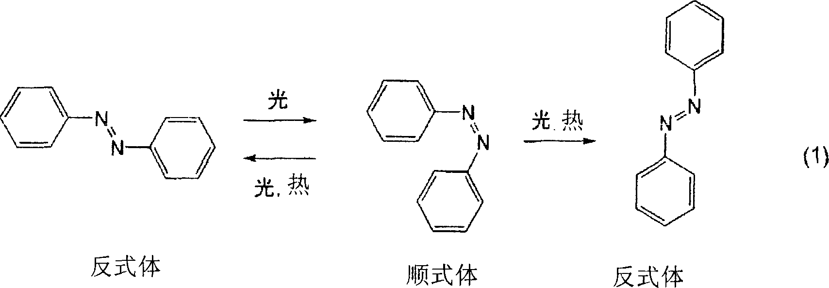
由于偶氮苯骨架的顺式体与反式体相比在化学上更不稳定,因此会因受热或吸收可见光而变回反式体,此时,是变为所述式(1)的左边的反式体还是变为右边的反式体,是以相同的概率发生的。由此,当继续吸收紫外光时,右侧的反式体的比例增加,偶氮苯骨架的平均取向方向变为与紫外光的偏振光方向垂直。本发明中,利用该现象使偶氮苯骨架的取向方向一致,对光取向膜赋予各向异性,控制该膜上的液晶分子的取向。Since the cis body of the azobenzene skeleton is chemically more unstable than the trans body, it will change back to the trans body due to heating or absorbing visible light. At this time, it becomes the left side of the formula (1). The trans body of the body or the trans body on the right side occur with the same probability. As a result, when ultraviolet light continues to be absorbed, the ratio of the trans-isomer on the right side increases, and the average orientation direction of the azobenzene skeleton becomes perpendicular to the polarization direction of ultraviolet light. In the present invention, this phenomenon is utilized to align the orientation directions of the azobenzene skeletons, impart anisotropy to the photo-alignment film, and control the orientation of liquid crystal molecules on the film.
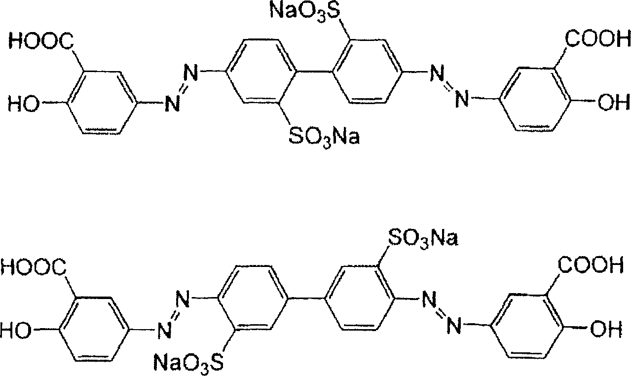
在本发明中所用的分子内具有偶氮苯骨架的化合物当中,作为单分子化合物,例如可以举出以下式表示的化合物。Among the compounds having an azobenzene skeleton in the molecule used in the present invention, examples of monomolecular compounds include compounds represented by the following formulas.
[化2][Chem 2]
所述式中,R21各自独立,表示羟基。R22表示以-(A21-B21-A21)m-(D21)n-表示的连结基,R23表示以(D21)n-(A21-B21-A21)m-表示的连结基。这里,A21表示二价的烃基,B21表示-O-、-COO-、-OCO-、-CONH-、-NHCO-、-NHCOO-或-OCONH-,m表示0~3的整数。D21在m为0时表示二价的烃基,在m为1~3的整数时表示-O-、-COO-、-OCO-、-CONH-、-NHCO-、-NHCOO-或-OCONH-,n表示0或1。R24各自独立,表示卤原子、羧基、卤化甲基、卤化甲氧基、氰基、硝基、甲氧基或甲氧基羰基。其中,羧基也可以与碱金属形成盐。R25各自独立,表示羧基、磺基、硝基、氨基或羟基。其中,羧基或磺基也可以与碱金属形成盐。In the formula, R 21 are each independently representing a hydroxyl group. R 22 represents a linking group represented by -(A 21 -B 21 -A 21 ) m -(D 21 ) n -, and R 23 represents a linking group represented by (D 21 ) n -(A 21 -B 21 -A 21 ) m - Represents the link base. Here, A 21 represents a divalent hydrocarbon group, B 21 represents -O-, -COO-, -OCO-, -CONH-, -NHCO-, -NHCOO- or -OCONH-, and m represents an integer of 0-3. D 21 represents a divalent hydrocarbon group when m is 0, and represents -O-, -COO-, -OCO-, -CONH-, -NHCO-, -NHCOO- or -OCONH- when m is an integer of 1 to 3 , n represents 0 or 1. R 24 each independently represent a halogen atom, a carboxyl group, a halogenated methyl group, a halogenated methoxy group, a cyano group, a nitro group, a methoxy group or a methoxycarbonyl group. Among them, the carboxyl group can also form a salt with an alkali metal. R 25 are each independently representing a carboxyl group, a sulfo group, a nitro group, an amino group or a hydroxyl group. Among them, the carboxyl group or sulfo group can also form a salt with an alkali metal.
作为以上述式表示的化合物的具体例,可以举出下述的化合物。Specific examples of the compound represented by the above formula include the following compounds.
[化3][Chem 3]
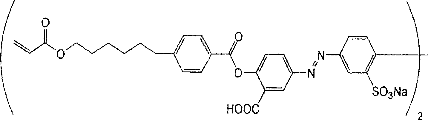
另外,作为本发明中所用的以偶氮苯骨架作为侧链而具有的聚合性单体,例如可以举出以下式表示的化合物。Moreover, as a polymerizable monomer which has an azobenzene skeleton as a side chain used in this invention, the compound represented by the following formula is mentioned, for example.
[化4][chemical 4]
上式中,R31各自独立,表示(甲基)丙烯酰氧基、(甲基)丙烯酰胺基、乙烯氧基、乙烯氧羰基、乙烯基亚氨基羰基、乙烯基亚氨基羰氧基、乙烯基、异丙烯氧基、异丙烯氧羰基、异丙烯基亚氨基羰基、异丙烯基亚氨基羰氧基、异丙烯基或环氧基。R32表示以-(A31-B31-A31)m-(D31)n-表示的连结基,R33表示以(D31)n-(A31-B31-A31)m-表示的连结基。这里,A31表示二价的烃基,B31表示-O-、-COO-、-OCO-、-CONH-、-NHCO-、-NHCOO-或-OCONH-,m表示0~3的整数。D31在m为0时表示二价的烃基,在m为1~3的整数时表示-O-、-COO-、-OCO-、-CONH-、-NHCO-、-NHCOO-或-OCONH-,n表示0或1。R34各自独立,表示卤原子、羧基、卤化甲基、卤化甲氧基、氰基、硝基、甲氧基或甲氧基羰基。其中,羧基也可以与碱金属形成盐。R35各自独立,表示羧基、磺基、硝基、氨基或羟基。其中,羧基或磺基也可以与碱金属形成盐。In the above formula, R 31 are each independently representing (meth)acryloyloxy, (meth)acrylamide, vinyloxy, vinyloxycarbonyl, vinyliminocarbonyl, vinyliminocarbonyloxy, vinyl group, isopropenyloxy, isopropenyloxycarbonyl, isopropenyliminocarbonyl, isopropenyliminocarbonyloxy, isopropenyl or epoxy. R 32 represents a linking group represented by -(A 31 -B 31 -A 31 ) m -(D 31 ) n -, and R 33 represents a linking group represented by (D 31 ) n -(A 31 -B 31 -A 31 ) m - Represents the link base. Here, A 31 represents a divalent hydrocarbon group, B 31 represents -O-, -COO-, -OCO-, -CONH-, -NHCO-, -NHCOO- or -OCONH-, and m represents an integer of 0-3. D 31 represents a divalent hydrocarbon group when m is 0, and represents -O-, -COO-, -OCO-, -CONH-, -NHCO-, -NHCOO- or -OCONH- when m is an integer of 1 to 3 , n represents 0 or 1. R 34 each independently represent a halogen atom, a carboxyl group, a halogenated methyl group, a halogenated methoxy group, a cyano group, a nitro group, a methoxy group or a methoxycarbonyl group. Among them, the carboxyl group can also form a salt with an alkali metal. R 35 each independently represent a carboxyl group, a sulfo group, a nitro group, an amino group or a hydroxyl group. Among them, the carboxyl group or sulfo group can also form a salt with an alkali metal.
作为以所述式表示的化合物的具体例,可以举出下述的化合物。Specific examples of the compound represented by the formula include the following compounds.
「化5]"Chem 5]
本发明中,通过从所述光异构化反应性化合物当中,根据要求特性,选择各种顺—反异构化反应性骨架或取代基,就可以使上下的光取向膜的组成不同。该情况下,作为上下的光取向膜中所用的光异构化反应性化合物,既可以使用顺—反异构化反应性骨架相同的,也可以使用不同的。另外,也可以将2种以上的光异构化反应性化合物组合使用,通过改变组合,或者虽然是相同的组合,但是改变组成比,就可以改变上下的光取向膜的组成。In the present invention, by selecting various cis-trans isomerization-reactive skeletons or substituents from the photo-isomerization-reactive compounds according to the required characteristics, the composition of the upper and lower photo-alignment films can be different. In this case, as the photo-isomerization-reactive compounds used in the upper and lower photo-alignment films, those having the same cis-trans isomerization-reactive skeleton may be used, or different ones may be used. In addition, two or more photoisomerization-reactive compounds may be used in combination, and the composition of the upper and lower photo-alignment films can be changed by changing the combination, or changing the composition ratio in spite of the same combination.
作为本发明中所用的光取向膜的构成材料,除了所述光异构化反应性化合物以外,还可以在不妨碍光取向膜的光排列性的范围内含有添加剂。在作为所述光异构化反应性化合物使用聚合性单体的情况下,作为添加剂,可以举出聚合引发剂、聚合抑制剂等。As a constituent material of the photo-alignment film used in the present invention, in addition to the above photoisomerization-reactive compound, additives may be contained within a range that does not interfere with the photo-alignment property of the photo-alignment film. When a polymerizable monomer is used as the photoisomerization-reactive compound, examples of the additive include a polymerization initiator, a polymerization inhibitor, and the like.
聚合引发剂或聚合抑制剂只要从一般公知的化合物之中,根据光异构化反应性化合物的种类适当地选择使用即可。聚合引发剂或聚合抑制剂的添加量相对于光异构化反应性化合物,优选0.001重量%~20重量%的范围内,更优选0.1重量%~5重量%的范围内。这是因为,当聚合引发剂或聚合抑制剂的添加量过小时,则会有聚合无法被引发(抑制)的情况,相反地,当过大时,则会有反应被阻碍的情况。A polymerization initiator or a polymerization inhibitor may be appropriately selected and used from generally known compounds according to the type of photoisomerization reactive compound. The amount of the polymerization initiator or polymerization inhibitor added is preferably within a range of 0.001% by weight to 20% by weight, more preferably within a range of 0.1% by weight to 5% by weight, based on the photoisomerization reactive compound. This is because, when the addition amount of the polymerization initiator or the polymerization inhibitor is too small, the polymerization may not be initiated (inhibited), and conversely, if it is too large, the reaction may be hindered.
如上所述,在本发明中光取向膜2a和光取向膜2b的构成材料为不同的组成。本发明中,虽然通过从所述光异构化反应性化合物中,根据要求特性,选择各种顺—反异构化反应性骨架或取代基,就可以使上下的光取向膜的组成不同,然而通过改变所述添加剂的添加量,也可以改变组成。As described above, in the present invention, the constituent materials of the photo-alignment film 2a and the photo-alignment film 2b have different compositions. In the present invention, although various cis-trans isomerization reactive skeletons or substituents are selected from the photoisomerization reactive compounds according to the required characteristics, the composition of the upper and lower photo-alignment films can be different, However, it is also possible to change the composition by changing the amount of the additives added.
下面,对光取向处理方法进行说明。首先,在设置了电极的基板的与液晶层相面对的面上,涂覆用有机溶剂将所述的光取向膜的构成材料稀释了的涂刷液,使之干燥。该情况下,涂刷液中的光异构化反应性化合物的含量优选0.05重量%~10重量%的范围内,更优选0.2重量%~5重量%的范围内。这是因为,当光异构化反应性化合物的含量过小时,则难以对取向膜赋予适度的各向异性,相反地,当过大时,则由于涂刷液的粘度变高,因此难以形成均匀的涂膜。Next, the photo-alignment treatment method will be described. First, a coating liquid obtained by diluting the constituent materials of the photo-alignment film with an organic solvent is applied to the surface of the substrate on which the electrodes are provided and faces the liquid crystal layer, and dried. In this case, the content of the photoisomerization-reactive compound in the coating liquid is preferably within a range of 0.05% by weight to 10% by weight, more preferably within a range of 0.2% by weight to 5% by weight. This is because, when the content of the photoisomerization-reactive compound is too small, it is difficult to impart appropriate anisotropy to the alignment film, and conversely, when it is too large, it is difficult to form Uniform coating film.
作为涂覆法,可以使用旋转涂覆法、滚筒涂覆法、条棒涂覆法、喷雾涂覆法、气刀涂覆法、狭缝模具涂覆法、条锭涂覆法等。As the coating method, a spin coating method, a roller coating method, a bar coating method, a spray coating method, an air knife coating method, a slot die coating method, a bar coating method, or the like can be used.
通过涂覆上述构成材料而得到的膜的厚度优选1nm~200nm的范围内,更优选3nm~100nm的范围内。这是因为,当所述膜的厚度过小时,则会有无法获得足够的光排列性的情况,相反,如果厚度过大,则会有产生液晶分子的取向紊乱的情况,另外,在成本上也不理想。The thickness of the film obtained by coating the above constituent materials is preferably within a range of 1 nm to 200 nm, more preferably within a range of 3 nm to 100 nm. This is because, when the thickness of the film is too small, sufficient optical alignment may not be obtained. On the contrary, if the thickness is too large, the orientation of the liquid crystal molecules may be disordered. Not ideal either.
所得的膜可以通过照射控制了偏振的光,产生光激发反应,来赋予各向异性。虽然所照射的光的波长区域只要根据所用的光取向膜的构成材料适当地选择即可,然而优选紫外光区域的范围内,即,100nm~400nm的范围内,更优选250nm~380nm的范围内。Anisotropy can be imparted to the obtained film by irradiating it with light with controlled polarization to cause a photoexcited reaction. Although the wavelength region of the light to be irradiated should be appropriately selected according to the constituent materials of the photo-alignment film used, it is preferably within the range of the ultraviolet light region, that is, within the range of 100nm to 400nm, more preferably within the range of 250nm to 380nm. .
另外,所述膜的光取向处理也可以通过斜向照射无偏振紫外线来进行。光的照射方向只要是可以产生所述光激发反应的方向,就没有特别限定,然而最好上下的光取向膜都设为相对于基板面倾斜10°~45°的范围内,更优选设为30°~45°的范围内,因为这样就可以将强介电性液晶的取向状态设为良好的状态。In addition, the photo-alignment treatment of the film can also be performed by obliquely irradiating unpolarized ultraviolet rays. The irradiation direction of light is not particularly limited as long as it is a direction in which the photoexcited reaction can occur, but it is preferable that the upper and lower photo-alignment films are all set within the range of inclination of 10° to 45° relative to the substrate surface, more preferably set to In the range of 30° to 45°, this is because the alignment state of the ferroelectric liquid crystal can be set to a good state.
在作为本发明中所用的光异构化反应性化合物,使用如上所述的聚合性单体的情况下,通过在进行了光取向处理后加热,就可以聚合物化,使向光取向膜赋予的各向异性稳定化。In the case of using the above-mentioned polymerizable monomer as the photoisomerization reactive compound used in the present invention, it can be polymerized by heating after photo-alignment treatment, so that the photo-alignment film imparted Anisotropic stabilization.
(2)液晶层(2) Liquid crystal layer
本发明中所用的液晶层是通过将强介电性液晶利用所述光取向膜夹持而构成的。所述液晶层中所用的强介电性液晶只要是呈现出手性近晶C相(SmC*)的液晶,就没有特别限定,然而优选强介电性液晶的相系列发生胆甾相(Ch)-手性近晶C相(SmC*)的相变而不经过近晶A相(SmA)的材料。The liquid crystal layer used in the present invention is constituted by sandwiching ferroelectric liquid crystals between the photo-alignment films. The ferroelectric liquid crystal used in the liquid crystal layer is not particularly limited as long as it exhibits a chiral smectic C phase (SmC * ), but it is preferable that the phase series of the ferroelectric liquid crystal exhibits a cholesteric phase (Ch). - Materials with a phase transition of the chiral smectic C phase (SmC * ) without going through the smectic A phase (SmA).
本发明的液晶显示元件最好利用使用了薄膜晶体管(TFT)的有源矩阵方式来驱动,另外可以通过采用滤色片方式或场序彩色方式来形成彩色液晶显示元件。此种情况下,作为强介电性液晶,既可以使用发生Ch相-SmA相-SmC*相的相变的材料,也可以使用发生Ch相-SmC*相的相变而不经过SmA相的材料,然而特别是在将本发明的液晶显示元件利用场序彩色方式驱动的情况下,优选使用不经过SmA相的具有单稳态性的液晶材料。这里,所谓单稳态性如上所述,是指在无电压施加时仅具有1个稳定状态的性质,特别是,仅在施加了正负任意一种电压时液晶分子才动作的半V形驱动的材料可以延长黑白快门的开口时间,可以实现明亮的彩色显示,在这一点上是理想的。The liquid crystal display device of the present invention is preferably driven by an active matrix method using thin film transistors (TFTs), and a color liquid crystal display device can be formed by using a color filter method or a field sequential color method. In this case, as the ferroelectric liquid crystal, it is possible to use either a material that undergoes a phase transition from Ch phase to SmA phase to SmC * phase, or a material that undergoes a phase transition from Ch phase to SmC * phase without going through the SmA phase. However, in particular, when the liquid crystal display device of the present invention is driven by a field sequential color method, it is preferable to use a liquid crystal material having a monostable state that does not pass through the SmA phase. Here, the so-called monostable property refers to the property of having only one stable state when no voltage is applied, in particular, half-V-shaped driving in which liquid crystal molecules move only when either positive or negative voltage is applied. The material can prolong the opening time of the black and white shutter, and can realize bright color display, which is ideal at this point.
另外,作为本发明中所用的强介电性液晶,优选构成单一相的材料。这里,所谓构成单一相是指,不像高分子稳态化法等那样形成聚合物网络。像这样,通过使用单一相的强介电性液晶,就会有制造过程变得容易,可以降低驱动电压的优点。In addition, as the ferroelectric liquid crystal used in the present invention, a material constituting a single phase is preferable. Here, constituting a single phase means that a polymer network is not formed as in a polymer stabilization method or the like. Thus, by using a single-phase ferroelectric liquid crystal, there is an advantage that the manufacturing process becomes easier and the driving voltage can be reduced.
作为本发明中所用的强介电性液晶,例如可以举出由Clariant公司销售的「R2301」。Examples of the ferroelectric liquid crystal used in the present invention include "R2301" sold by Clariant.
所述由强介电性液晶构成的液晶层的厚度优选1.2μm~3.0μm的范围内,更优选1.3μm~2.5μm,进一步优选1.4μm~2.0μm的范围内。这是因为,当液晶层的厚度过小时,则会有对比度降低的情况,相反,当厚度过大时,则会有难以取向的情况。The thickness of the liquid crystal layer made of ferroelectric liquid crystal is preferably in the range of 1.2 μm to 3.0 μm, more preferably in the range of 1.3 μm to 2.5 μm, even more preferably in the range of 1.4 μm to 2.0 μm. This is because when the thickness of the liquid crystal layer is too small, the contrast may be lowered, and conversely, when the thickness is too large, alignment may be difficult.
作为液晶层的形成方法,可以使用一般被作为液晶单元的制作方法所使用的方法。例如,可以向预先在基板上形成电极,设置所述光取向膜而制成的液晶单元中,利用毛细管效应注入通过将所述强介电性液晶加温而形成的各向同性液体,通过用粘接剂密封而形成液晶层。所述液晶层的厚度可以利用珠子等间隔物来调整。As a method for forming a liquid crystal layer, a method generally used as a method for producing a liquid crystal cell can be used. For example, the isotropic liquid formed by heating the ferroelectric liquid crystal can be injected into the liquid crystal cell made by forming electrodes on the substrate in advance and setting the photo-alignment film by utilizing the capillary effect. The adhesive is sealed to form a liquid crystal layer. The thickness of the liquid crystal layer can be adjusted by spacers such as beads.
(3)基板(3) Substrate
本发明中所用的基板只要是一般被作为液晶显示元件的基板使用的,就没有特别限定,例如可以优选地举出玻璃板、塑料板等。所述基板的表面粗糙度(RSM值)优选10nm以下,更优选3nm以下,进一步优选1nm以下的范围内。而且,本发明中,所述表面粗糙度可以利用原子间力显微镜(AFM.ATOMIC FORCE MICROSCOPE)来测定。The substrate used in the present invention is not particularly limited as long as it is generally used as a substrate of a liquid crystal display element, and examples thereof preferably include a glass plate, a plastic plate, and the like. The surface roughness (RSM value) of the substrate is preferably within a range of 10 nm or less, more preferably 3 nm or less, and still more preferably 1 nm or less. Moreover, in the present invention, the surface roughness can be measured using an atomic force microscope (AFM. ATOMIC FORCE MICROSCOPE).
(4)电极(4) Electrodes
本发明中所用的电极只要是一般被作为液晶显示元件的电极使用的,就没有特别限定,最好至少一方由透明导电体形成。作为透明导电体材料,可以优选地举出氧化铟、氧化锡、氧化铟锡(ITO)等。在将本发明的液晶显示元件设为使用了TFT元件的有源矩阵方式的液晶显示元件的情况下,将上下的电极当中的一方设为由所述透明导电体形成的全面公共电极,对于另一方则是将x电极和y电极以矩阵状排列,在由x电极和y电极包围的部分中配置TFT元件及象素电极。该情况下,由象素电极、TFT元件、x电极及y电极形成的电极层的凹凸部的差优选0.2μm以下。这是因为,当电极层的凹凸部的差超过0.2μm时,则容易产生取向紊乱。The electrodes used in the present invention are not particularly limited as long as they are generally used as electrodes of liquid crystal display elements, but at least one of them is preferably formed of a transparent conductor. Examples of the transparent conductor material preferably include indium oxide, tin oxide, indium tin oxide (ITO), and the like. When the liquid crystal display element of the present invention is an active matrix liquid crystal display element using a TFT element, one of the upper and lower electrodes is a full-surface common electrode formed of the transparent conductor, and the other On the other hand, x electrodes and y electrodes are arranged in a matrix, and TFT elements and pixel electrodes are arranged in a portion surrounded by the x electrodes and y electrodes. In this case, the difference between the unevenness of the electrode layer formed by the pixel electrode, the TFT element, the x electrode, and the y electrode is preferably 0.2 μm or less. This is because, when the difference between the concave and convex portions of the electrode layer exceeds 0.2 μm, orientation disorder tends to occur.
所述电极可以利用CVD法、溅射法、离子注入法等蒸镀方法在所述基板上形成透明导电膜,通过将其以矩阵状进行图案处理,就可以得到x电极及y电极。The electrodes can be formed on the substrate by vapor deposition methods such as CVD, sputtering, and ion implantation, and patterned in a matrix to obtain x electrodes and y electrodes.
(5)偏振片(5) Polarizer
本发明中所用的偏振片只要是仅使光波当中的特定方向的部分透过的材料,就没有特别限定,可以使用一般被作为液晶显示元件的偏振片使用的材料。The polarizing plate used in the present invention is not particularly limited as long as it transmits only part of light waves in a specific direction, and materials generally used as polarizing plates of liquid crystal display elements can be used.
2.液晶显示元件的制造方法2. Manufacturing method of liquid crystal display element
本发明的液晶显示元件可以利用作为液晶显示元件的制造方法所一般使用的方法来制造。以下,作为本发明的液晶显示元件的制造方法的一个例子,对使用了TFT元件的有源矩阵方式的液晶显示元件的制造方法进行说明。首先,在一方的基板上利用所述的蒸镀方法形成透明导电膜,制成全面公共电极。在另一方的基板上,通过将透明导电膜以矩阵状进行图案处理,形成x电极、y电极,设置开关元件及象素电极。The liquid crystal display element of this invention can be manufactured by the method generally used as a manufacturing method of a liquid crystal display element. Hereinafter, as an example of the method of manufacturing a liquid crystal display element of the present invention, a method of manufacturing an active matrix liquid crystal display element using a TFT element will be described. First, a transparent conductive film is formed on one substrate by the vapor deposition method described above to form a full-surface common electrode. On the other substrate, x-electrodes and y-electrodes are formed by patterning a transparent conductive film in a matrix, and switching elements and pixel electrodes are provided.
然后,在形成了电极的2张基板上分别涂覆组成不同的光取向膜材料,实施光取向处理,形成光取向膜。在像这样形成的光取向膜当中的一方的取向膜上,作为间隔物分散珠子,在周围涂布密封剂,使光取向膜相面对地将2张基板贴合,将其热压接。此后,利用毛细管效应,从注入口将强介电性液晶以各向同性液体的状态注入,利用紫外线固化树脂等将注入口封堵。其后,通过将强介电性液晶缓慢冷却而可以使之取向。通过在如此得到的液晶单元的上下贴附偏振片,就可以得到本发明的液晶显示元件。Then, photo-alignment film materials having different compositions were coated on the two substrates on which the electrodes were formed, and photo-alignment treatment was performed to form a photo-alignment film. On one of the photo-alignment films thus formed, beads were dispersed as spacers, a sealant was applied around the periphery, and two substrates were laminated so that the photo-alignment films faced each other, and bonded by thermocompression. Thereafter, the ferroelectric liquid crystal is injected from the injection port in the state of an isotropic liquid by utilizing the capillary effect, and the injection port is sealed with ultraviolet curable resin or the like. Thereafter, the ferroelectric liquid crystal can be aligned by gradually cooling it. The liquid crystal display element of the present invention can be obtained by affixing polarizing plates on the upper and lower sides of the liquid crystal cell thus obtained.
3.液晶显示元件的用途3. Application of liquid crystal display components
本发明的液晶显示元件通过采用滤色片方式或场序彩色方式,可以作为彩色液晶显示元件使用。使用了本发明的液晶显示元件的彩色液晶显示元件由于可以不产生双畴等取向缺陷地将强介电性液晶取向,因此视角宽,具有高速响应性,可以实现高精细的彩色显示。The liquid crystal display element of the present invention can be used as a color liquid crystal display element by employing a color filter system or a field sequential color system. The color liquid crystal display element using the liquid crystal display element of the present invention can align ferroelectric liquid crystals without causing alignment defects such as double domains, and therefore has a wide viewing angle, high-speed response, and high-definition color display.
它们当中,本发明的液晶显示元件优选利用场序彩色方式来驱动。这是因为,如上所述,场序彩色方式是将1个象素进行时间分割的方式,为了获得良好的动画显示特性,特别需要高速响应性。Among them, the liquid crystal display element of the present invention is preferably driven by a field sequential color method. This is because, as described above, the field sequential color method is a method in which one pixel is time-divided, and in order to obtain good animation display characteristics, particularly high-speed responsiveness is required.
该情况下,作为强介电性液晶,优选使用从Ch相不经过SmA相而呈现SmC*相的具有单稳态性的液晶材料,特别优选使用仅在施加了正负任意一种电压时液晶分子才动作的半V形驱动的材料。通过使用此种半V字驱动的材料,可以减少暗部动作时(黑白快门闭口时)的光泄漏,可以充分地延长作为黑白快门的开口时间。这样就可以将随时间被切换的各色更为明亮地显示,可以实现明亮的彩色液晶显示元件。In this case, as the ferroelectric liquid crystal, it is preferable to use a liquid crystal material having a monostable state that exhibits the SmC * phase from the Ch phase without passing through the SmA phase, and it is particularly preferable to use a liquid crystal material that can only be used when either positive or negative voltage is applied. A semi-V-shaped driven material that only moves molecules. By using such a half-V-shaped driving material, the light leakage during dark operation (when the black and white shutter is closed) can be reduced, and the opening time of the black and white shutter can be sufficiently extended. In this way, each color switched over time can be displayed more brightly, and a bright color liquid crystal display element can be realized.
而且,本发明并不限定于所述实施方式。所述实施方式只是示例性的,具有与本发明的技术方案的范围中所记载的技术思想实质上相同的构成,起到相同的作用的方案无论为何种方式,都包含于本发明的技术范围中。Moreover, this invention is not limited to the said embodiment. The above-described embodiments are merely exemplary, and have substantially the same configuration as the technical idea described in the scope of the technical claims of the present invention, and those that perform the same functions are included in the technical scope of the present invention regardless of their form. middle.
实施例Example
下面将出示实施例,对本发明进行进一步详细说明。而且,作为光异构化反应性化合物,使用了以下式表示的化合物1~6。Examples will be shown below to further describe the present invention in detail. In addition, as photoisomerization reactive compounds, compounds 1 to 6 represented by the following formulas were used.
[化6][chemical 6]
(实施例1)(Example 1)
将溶解于N-甲基-2-吡咯烷酮和2-n-丁氧基乙醇(50∶50w%)中的1重量%的化合物1的溶液与溶解于N-甲基-2-吡咯烷酮和2-n-丁氧基乙醇(50∶50w%)中的1重量%的化合物5的溶液,分别在被用ITO涂覆了的2片玻璃基板上以转速4000rpm进行了30秒的旋转涂覆。在烤炉中进行了100℃、1分钟干燥后,在25℃下以1000mJ/cm2进行了偏振紫外线的曝光。另外,对于旋转涂覆了化合物5的溶液的基板,在曝光后,在氮气气氛下150℃加热1小时。在一方的基板上撒布1.5μm的间隔臂,在另一方的基板上用密封给料器涂布密封材料。其后,将基板以与偏振紫外线照射方向平行并且反平行的状态组装,进行了热压接。液晶使用「2301」(Clariant公司制),在注入口上部附着液晶,使用烤炉,以比向列相—各向同性相转移温度高10℃~20℃的温度进行注入,在慢慢地回到常温后,得到了没有取向缺陷的单畴相。A solution of 1% by weight of compound 1 dissolved in N-methyl-2-pyrrolidone and 2-n-butoxyethanol (50:50w%) was mixed with a solution of 1% by weight dissolved in N-methyl-2-pyrrolidone and 2- A solution of 1% by weight of compound 5 in n-butoxyethanol (50:50w%) was spin-coated on two glass substrates coated with ITO at 4000 rpm for 30 seconds. After drying in an oven at 100° C. for 1 minute, exposure to polarized ultraviolet rays was performed at 25° C. at 1000 mJ/cm 2 . In addition, the substrate on which the solution of Compound 5 was spin-coated was heated at 150° C. for 1 hour in a nitrogen atmosphere after exposure. A 1.5 μm spacer was sprinkled on one substrate, and a sealing material was applied to the other substrate with a seal dispenser. Thereafter, the substrates were assembled in a state parallel to and antiparallel to the polarized ultraviolet irradiation direction, and thermocompression bonding was performed. The liquid crystal is "2301" (manufactured by Clariant Co., Ltd.), and the liquid crystal is attached to the upper part of the injection port. Using an oven, inject at a temperature 10°C to 20°C higher than the nematic phase-isotropic phase transition temperature, and slowly return to the liquid crystal. After reaching room temperature, a single-domain phase without orientation defects was obtained.
(比较例1)(comparative example 1)
将溶解于N-甲基-2-吡咯烷酮和2-n-丁氧基乙醇(50∶50w%)中的1重量%的化合物1的溶液,在被用ITO涂覆了的2片玻璃基板上以转速4000rpm进行了30秒的旋转涂覆。其后,在与实施例1相同地进行了干燥后,进行曝光处理,曝光后,在氮气气氛下150℃加热1小时。继而,用上面所述的方法组装液晶单元,注入了液晶,结果未得到单畴相,产生了双畴或锯齿缺陷、发夹缺陷等取向缺陷。A solution of 1% by weight of compound 1 dissolved in N-methyl-2-pyrrolidone and 2-n-butoxyethanol (50:50w%) was placed on 2 glass substrates coated with ITO Spin coating was performed at a rotation speed of 4000 rpm for 30 seconds. Thereafter, after drying in the same manner as in Example 1, an exposure treatment was performed, and after exposure, it was heated at 150° C. for 1 hour in a nitrogen atmosphere. Next, when a liquid crystal cell was assembled by the method described above, and liquid crystal was injected, a single domain phase was not obtained, but alignment defects such as double domains, zigzag defects, and hairpin defects occurred.
(比较例2)(comparative example 2)
将溶解于N-甲基-2-吡咯烷酮和2-n-丁氧基乙醇(50∶50w%)中的1重量%的化合物5的溶液,在被用ITO涂覆了的2片玻璃基板上以转速4000rpm进行了30秒的旋转涂覆。其后,在与实施例1相同地进行了干燥后,进行曝光处理,曝光后,在氮气气氛下150℃加热1小时。继而,用上面所述的方法组装液晶单元,注入了液晶,结果未得到单畴相,产生了双畴或锯齿缺陷、发夹缺陷等取向缺陷。A solution of 1% by weight of compound 5 dissolved in N-methyl-2-pyrrolidone and 2-n-butoxyethanol (50:50w%) was placed on 2 glass substrates coated with ITO Spin coating was performed at a rotation speed of 4000 rpm for 30 seconds. Thereafter, after drying in the same manner as in Example 1, an exposure treatment was performed, and after exposure, it was heated at 150° C. for 1 hour in a nitrogen atmosphere. Next, when a liquid crystal cell was assembled by the method described above, and liquid crystal was injected, a single domain phase was not obtained, but alignment defects such as double domains, zigzag defects, and hairpin defects occurred.
(实施例2)(Example 2)
除了取代实施例1的化合物1而使用了化合物2以外,与实施例1相同进行后,得到了没有取向缺陷的单畴相。A monodomain phase free of alignment defects was obtained in the same manner as in Example 1 except that Compound 2 was used instead of Compound 1 in Example 1.
(实施例3)(Example 3)
将溶解于N-甲基-2-吡咯烷酮和2-n-丁氧基乙醇(50∶50w%)中的1重量%的化合物3的溶液与溶解于N-甲基-2-吡咯烷酮和2-n-丁氧基乙醇(50∶50w%)中的1重量%的化合物5的溶液,分别在被用ITO涂覆了的2片玻璃基板上以转速4000rpm进行了30秒的旋转涂覆。在烤炉中进行了100℃、1分钟干燥后,在25℃下以1000mJ/cm2进行了偏振紫外线的曝光。另外,在曝光后,在氮气气氛下150℃加热1小时。在一方的基板上撒布1.5μm的间隔臂,在另一方的基板上用密封给料器涂布了密封材料。其后,将基板以与偏振紫外线照射方向平行并且反平行的状态组装,进行了热压接。液晶使用「2301」(Clariant公司制),在注入口上部附着液晶,使用烤炉,以比向列相—各向同性相转移温度高10℃~20℃的温度进行注入,在慢慢地回到常温,结果得到了没有取向缺陷的单畴相。A solution of 1% by weight of compound 3 dissolved in N-methyl-2-pyrrolidone and 2-n-butoxyethanol (50:50w%) was mixed with a solution of 1% by weight dissolved in N-methyl-2-pyrrolidone and 2- A solution of 1% by weight of compound 5 in n-butoxyethanol (50:50w%) was spin-coated on two glass substrates coated with ITO at 4000 rpm for 30 seconds. After drying in an oven at 100° C. for 1 minute, exposure to polarized ultraviolet rays was performed at 25° C. at 1000 mJ/cm 2 . Moreover, after exposure, it heated at 150 degreeC for 1 hour in nitrogen atmosphere. Spacers of 1.5 μm were sprinkled on one substrate, and a sealing material was applied to the other substrate with a seal dispenser. Thereafter, the substrates were assembled in a state parallel to and antiparallel to the polarized ultraviolet irradiation direction, and thermocompression bonding was performed. The liquid crystal is "2301" (manufactured by Clariant Co., Ltd.), and the liquid crystal is attached to the upper part of the injection port. Using an oven, inject at a temperature 10°C to 20°C higher than the nematic phase-isotropic phase transition temperature, and slowly return to the liquid crystal. to room temperature, the result is a monodomain phase without orientation defects.
(实施例4)(Example 4)
除了取代实施例3的化合物3而使用了化合物4以外,与实施例1相同进行,结果得到了没有取向缺陷的单畴相。In the same manner as in Example 1 except that Compound 4 was used instead of Compound 3 in Example 3, a monodomain phase free of orientation defects was obtained.
(实施例5)(Example 5)
除了取代实施例1的化合物5而使用了化合物3以外,与实施例1相同进行,结果得到了没有取向缺陷的单畴相。In the same manner as in Example 1 except that Compound 3 was used instead of Compound 5 in Example 1, a monodomain phase free of orientation defects was obtained.
(实施例6)(Example 6)
除了取代实施例1的化合物5而使用了化合物4以外,与实施例1相同进行,结果得到了没有取向缺陷的单畴相。In the same manner as in Example 1 except that Compound 4 was used instead of Compound 5 in Example 1, a monodomain phase free of orientation defects was obtained.
(实施例7)(Example 7)
将溶解于N-甲基-2-吡咯烷酮和2-n-丁氧基乙醇(50∶50w%)中的1重量%的化合物5的溶液与溶解于N-甲基-2-吡咯烷酮和2-n-丁氧基乙醇(50∶50w%)中的1重量%的化合物6的溶液,分别在被用ITO涂覆了的2片玻璃基板上以转速4000rpm进行了30秒的旋转涂覆。在烤炉中进行了100℃、1分钟干燥后,在25℃下以1000mJ/cm2进行了偏振紫外线的曝光。另外,对于旋转涂覆了化合物5的溶液的基板,在曝光后,在氮气气氛下150℃加热1小时。在一方的基板上撒布1.5μm的间隔臂,在另一方的基板上用密封给料器涂布了密封材料。其后,将基板以与偏振紫外线照射方向平行并且反平行的状态组装,进行了热压接。液晶使用「2301」(Clariant公司制),在注入口上部附着液晶,使用烤炉,以比向列相—各向同性相转移温度高10℃~20℃的温度进行注入,在慢慢地回到常温,结果得到了没有取向缺陷的单畴相。A solution of 1% by weight of compound 5 dissolved in N-methyl-2-pyrrolidone and 2-n-butoxyethanol (50:50w%) was mixed with a solution of 1% by weight dissolved in N-methyl-2-pyrrolidone and 2- A solution of 1% by weight of compound 6 in n-butoxyethanol (50:50w%) was spin-coated on two glass substrates coated with ITO at 4000 rpm for 30 seconds. After drying in an oven at 100° C. for 1 minute, exposure to polarized ultraviolet rays was performed at 25° C. at 1000 mJ/cm 2 . In addition, the substrate on which the solution of Compound 5 was spin-coated was heated at 150° C. for 1 hour in a nitrogen atmosphere after exposure. Spacers of 1.5 μm were sprinkled on one substrate, and a sealing material was applied to the other substrate with a seal dispenser. Thereafter, the substrates were assembled in a state parallel to and antiparallel to the polarized ultraviolet irradiation direction, and thermocompression bonding was performed. The liquid crystal is "2301" (manufactured by Clariant Co., Ltd.), and the liquid crystal is attached to the upper part of the injection port. Using an oven, inject at a temperature 10°C to 20°C higher than the nematic phase-isotropic phase transition temperature, and slowly return to the liquid crystal. to room temperature, the result is a monodomain phase without orientation defects.
Claims (11)
Applications Claiming Priority (2)
| Application Number | Priority Date | Filing Date | Title |
|---|---|---|---|
| JP014972/2004 | 2004-01-22 | ||
| JP2004014972 | 2004-01-22 |
Publications (2)
| Publication Number | Publication Date |
|---|---|
| CN1910509A true CN1910509A (en) | 2007-02-07 |
| CN100520536C CN100520536C (en) | 2009-07-29 |
Family
ID=34805440
Family Applications (1)
| Application Number | Title | Priority Date | Filing Date |
|---|---|---|---|
| CNB2005800029865A Expired - Fee Related CN100520536C (en) | 2004-01-22 | 2005-01-19 | Liquid crystal display element |
Country Status (7)
| Country | Link |
|---|---|
| US (2) | US7553525B2 (en) |
| EP (1) | EP1715371B1 (en) |
| JP (2) | JP4753149B2 (en) |
| KR (1) | KR101073722B1 (en) |
| CN (1) | CN100520536C (en) |
| DE (1) | DE602005024519D1 (en) |
| WO (1) | WO2005071476A1 (en) |
Cited By (3)
| Publication number | Priority date | Publication date | Assignee | Title |
|---|---|---|---|---|
| CN103890648A (en) * | 2011-10-03 | 2014-06-25 | 罗利克有限公司 | Photo-alignment layer with strong UV-dichroism |
| CN104777673A (en) * | 2015-04-24 | 2015-07-15 | 深圳市华星光电技术有限公司 | Display panel and manufacturing method thereof |
| CN104777672A (en) * | 2015-04-24 | 2015-07-15 | 深圳市华星光电技术有限公司 | Display panel and manufacturing method thereof |
Families Citing this family (12)
| Publication number | Priority date | Publication date | Assignee | Title |
|---|---|---|---|---|
| KR101021696B1 (en) | 2005-05-19 | 2011-03-15 | 다이니폰 인사츠 가부시키가이샤 | Liquid crystal display device |
| JP4661502B2 (en) * | 2005-09-29 | 2011-03-30 | Dic株式会社 | Composition for photo-alignment film and method for producing photo-alignment film |
| JP5165228B2 (en) * | 2005-11-01 | 2013-03-21 | 香港科技大学 | A rewritable, liquid crystal element with optical input by optical input for display |
| JP5076458B2 (en) | 2006-11-24 | 2012-11-21 | 大日本印刷株式会社 | Liquid crystal display element |
| US8139189B2 (en) | 2006-12-20 | 2012-03-20 | Dai Nippon Printing Co., Ltd. | Liquid crystal display having particular oblique vapor deposition-alignment layer with ferroelectric liquid crystal |
| US12377189B2 (en) | 2008-12-13 | 2025-08-05 | Bioventus Llc | Osteoinductive bone implant including harvested demineralized bone and bone morphogenetic proteins bound thereto obtained from the same donor |
| US8221592B2 (en) * | 2009-11-18 | 2012-07-17 | Korea University Research And Business Foundation | Method for sorting carbon nanotubes (CNTs) and device for CNTs sorting |
| CN102781487B (en) * | 2009-12-13 | 2016-11-16 | 阿米特·普拉卡什·戈维 | bioactive grafts and composites |
| US20110298999A1 (en) * | 2010-06-08 | 2011-12-08 | Reald Inc. | Stereoscopic liquid crystal display systems |
| KR101668381B1 (en) | 2013-09-30 | 2016-10-31 | 삼성디스플레이 주식회사 | Liquid crystal display and method of manufacturing the same |
| KR102051113B1 (en) * | 2013-12-18 | 2019-12-03 | 삼성디스플레이 주식회사 | Liquid crystal display and method of manufacturing the same |
| KR20160014179A (en) | 2014-07-28 | 2016-02-11 | 삼성디스플레이 주식회사 | Method of driving display panel and display apparatus for performing the same |
Family Cites Families (17)
| Publication number | Priority date | Publication date | Assignee | Title |
|---|---|---|---|---|
| JP2667816B2 (en) * | 1986-09-20 | 1997-10-27 | キヤノン株式会社 | Liquid crystal element |
| US6160597A (en) * | 1993-02-17 | 2000-12-12 | Rolic Ag | Optical component and method of manufacture |
| JPH08328005A (en) * | 1995-05-26 | 1996-12-13 | Hitachi Chem Co Ltd | Liquid crystal oriented film, treatment of liquid crystal oriented film, liquid crystal holding substrate, liquid crystal display element, production of liquid crystal display element and material for liquid crystal oriented film |
| US6107427A (en) * | 1995-09-15 | 2000-08-22 | Rolic Ag | Cross-linkable, photoactive polymer materials |
| US5977942A (en) * | 1996-12-20 | 1999-11-02 | Compaq Computer Corporation | Multiplexed display element sequential color LCD panel |
| JPH1184390A (en) * | 1997-09-16 | 1999-03-26 | Canon Inc | Liquid crystal element and manufacturing method thereof |
| US6153272A (en) * | 1998-05-18 | 2000-11-28 | University Of Massachusetts Lowell | Liquid crystal alignment by covalently bound anisotropes |
| US7317438B2 (en) * | 1998-10-30 | 2008-01-08 | Semiconductor Energy Laboratory Co., Ltd. | Field sequential liquid crystal display device and driving method thereof, and head mounted display |
| GB9905579D0 (en) * | 1999-03-12 | 1999-05-05 | Secr Defence | Photoactive pentaerythritol derivatives and orientation layers |
| US6582776B2 (en) * | 2000-11-24 | 2003-06-24 | Hong Kong University Of Science And Technology | Method of manufacturing photo-alignment layer |
| KR100752505B1 (en) | 2000-12-30 | 2007-08-28 | 엘지.필립스 엘시디 주식회사 | Ferroelectric liquid crystal display |
| DE60232289D1 (en) * | 2001-04-06 | 2009-06-25 | Merck Patent Gmbh | Photopolymerizable compounds |
| US20030072896A1 (en) | 2001-06-07 | 2003-04-17 | The Hong Kong University Of Science And Technology | Photo-induced alignment materials and method for LCD fabrication |
| JP2003005223A (en) | 2001-06-25 | 2003-01-08 | Science Univ Of Tokyo | Method for manufacturing liquid crystal display device with high contrast ratio asymmetric electro-optical characteristics |
| JP4040377B2 (en) | 2001-07-16 | 2008-01-30 | 株式会社半導体エネルギー研究所 | Method for manufacturing liquid crystal display device |
| US6824707B2 (en) * | 2001-10-23 | 2004-11-30 | Clariant International Ltd. | Active matrix liquid crystal device and smectic liquid crystal mixture |
| US6919404B2 (en) * | 2002-05-31 | 2005-07-19 | Elsicon, Inc. | Hybrid polymer materials for liquid crystal alignment layers |
-
2005
- 2005-01-19 US US10/587,140 patent/US7553525B2/en not_active Expired - Fee Related
- 2005-01-19 JP JP2005011689A patent/JP4753149B2/en not_active Expired - Fee Related
- 2005-01-19 EP EP05709245A patent/EP1715371B1/en not_active Expired - Fee Related
- 2005-01-19 CN CNB2005800029865A patent/CN100520536C/en not_active Expired - Fee Related
- 2005-01-19 DE DE602005024519T patent/DE602005024519D1/en not_active Expired - Lifetime
- 2005-01-19 WO PCT/JP2005/000615 patent/WO2005071476A1/en not_active Ceased
-
2006
- 2006-08-21 KR KR1020067016739A patent/KR101073722B1/en not_active Expired - Fee Related
-
2008
- 2008-11-20 US US12/274,525 patent/US7599041B2/en not_active Expired - Fee Related
-
2011
- 2011-03-14 JP JP2011055539A patent/JP5007771B2/en not_active Expired - Fee Related
Cited By (5)
| Publication number | Priority date | Publication date | Assignee | Title |
|---|---|---|---|---|
| CN103890648A (en) * | 2011-10-03 | 2014-06-25 | 罗利克有限公司 | Photo-alignment layer with strong UV-dichroism |
| CN103890648B (en) * | 2011-10-03 | 2019-06-18 | 罗利克有限公司 | Photoalignment layer with strong UV-dichroism |
| CN104777673A (en) * | 2015-04-24 | 2015-07-15 | 深圳市华星光电技术有限公司 | Display panel and manufacturing method thereof |
| CN104777672A (en) * | 2015-04-24 | 2015-07-15 | 深圳市华星光电技术有限公司 | Display panel and manufacturing method thereof |
| US10591778B2 (en) | 2015-04-24 | 2020-03-17 | Shenzhen China Star Optoelectronics Technology Co., Ltd. | Display panel and manufacturing method thereof |
Also Published As
| Publication number | Publication date |
|---|---|
| EP1715371A4 (en) | 2008-04-02 |
| US7553525B2 (en) | 2009-06-30 |
| KR20070001961A (en) | 2007-01-04 |
| US20070154653A1 (en) | 2007-07-05 |
| US7599041B2 (en) | 2009-10-06 |
| JP2011118433A (en) | 2011-06-16 |
| JP2005234549A (en) | 2005-09-02 |
| EP1715371A1 (en) | 2006-10-25 |
| CN100520536C (en) | 2009-07-29 |
| US20090142865A1 (en) | 2009-06-04 |
| JP4753149B2 (en) | 2011-08-24 |
| KR101073722B1 (en) | 2011-10-13 |
| DE602005024519D1 (en) | 2010-12-16 |
| WO2005071476A1 (en) | 2005-08-04 |
| JP5007771B2 (en) | 2012-08-22 |
| EP1715371B1 (en) | 2010-11-03 |
Similar Documents
| Publication | Publication Date | Title |
|---|---|---|
| JP5007771B2 (en) | Liquid crystal display element | |
| JP5402999B2 (en) | Liquid crystal display element | |
| CN101364012B (en) | Liquid crystal display element | |
| CN100523958C (en) | Liquid crystal display element | |
| JP4528645B2 (en) | Liquid crystal display element | |
| US20050266177A1 (en) | Liquid crystal display | |
| US7553521B2 (en) | Liquid crystal displays | |
| JP4520314B2 (en) | Liquid crystal display element | |
| JP4676214B2 (en) | Liquid crystal display element | |
| JP4839959B2 (en) | Liquid crystal display element | |
| JP2005258429A (en) | Liquid crystal display element | |
| JP4756325B2 (en) | Liquid crystal display element and method for manufacturing liquid crystal display element | |
| JP2010230900A (en) | Liquid crystal display element | |
| JP2006323214A (en) | Liquid crystal display element | |
| JP2006323216A (en) | Liquid crystal display element and method for manufacturing liquid crystal display element | |
| JP2011150361A (en) | Liquid crystal display element and method for manufacturing liquid crystal display element |
Legal Events
| Date | Code | Title | Description |
|---|---|---|---|
| C06 | Publication | ||
| PB01 | Publication | ||
| C10 | Entry into substantive examination | ||
| SE01 | Entry into force of request for substantive examination | ||
| C14 | Grant of patent or utility model | ||
| GR01 | Patent grant | ||
| CF01 | Termination of patent right due to non-payment of annual fee |
Granted publication date: 20090729 Termination date: 20150119 |
|
| EXPY | Termination of patent right or utility model |