CN1737696A - Photosensitive member cartridge, developer cartridge and process cartridge - Google Patents
Photosensitive member cartridge, developer cartridge and process cartridge Download PDFInfo
- Publication number
- CN1737696A CN1737696A CNA2005100911072A CN200510091107A CN1737696A CN 1737696 A CN1737696 A CN 1737696A CN A2005100911072 A CNA2005100911072 A CN A2005100911072A CN 200510091107 A CN200510091107 A CN 200510091107A CN 1737696 A CN1737696 A CN 1737696A
- Authority
- CN
- China
- Prior art keywords
- developer
- box
- side wall
- electrode
- wall
- Prior art date
- Legal status (The legal status is an assumption and is not a legal conclusion. Google has not performed a legal analysis and makes no representation as to the accuracy of the status listed.)
- Granted
Links
Images


Classifications
-
- G—PHYSICS
- G03—PHOTOGRAPHY; CINEMATOGRAPHY; ANALOGOUS TECHNIQUES USING WAVES OTHER THAN OPTICAL WAVES; ELECTROGRAPHY; HOLOGRAPHY
- G03G—ELECTROGRAPHY; ELECTROPHOTOGRAPHY; MAGNETOGRAPHY
- G03G15/00—Apparatus for electrographic processes using a charge pattern
- G03G15/06—Apparatus for electrographic processes using a charge pattern for developing
-
- G—PHYSICS
- G03—PHOTOGRAPHY; CINEMATOGRAPHY; ANALOGOUS TECHNIQUES USING WAVES OTHER THAN OPTICAL WAVES; ELECTROGRAPHY; HOLOGRAPHY
- G03G—ELECTROGRAPHY; ELECTROPHOTOGRAPHY; MAGNETOGRAPHY
- G03G21/00—Arrangements not provided for by groups G03G13/00 - G03G19/00, e.g. cleaning, elimination of residual charge
- G03G21/16—Mechanical means for facilitating the maintenance of the apparatus, e.g. modular arrangements
- G03G21/18—Mechanical means for facilitating the maintenance of the apparatus, e.g. modular arrangements using a processing cartridge, whereby the process cartridge comprises at least two image processing means in a single unit
- G03G21/1839—Means for handling the process cartridge in the apparatus body
- G03G21/1857—Means for handling the process cartridge in the apparatus body for transmitting mechanical drive power to the process cartridge, drive mechanisms, gears, couplings, braking mechanisms
-
- B—PERFORMING OPERATIONS; TRANSPORTING
- B41—PRINTING; LINING MACHINES; TYPEWRITERS; STAMPS
- B41J—TYPEWRITERS; SELECTIVE PRINTING MECHANISMS, i.e. MECHANISMS PRINTING OTHERWISE THAN FROM A FORME; CORRECTION OF TYPOGRAPHICAL ERRORS
- B41J2/00—Typewriters or selective printing mechanisms characterised by the printing or marking process for which they are designed
-
- G—PHYSICS
- G03—PHOTOGRAPHY; CINEMATOGRAPHY; ANALOGOUS TECHNIQUES USING WAVES OTHER THAN OPTICAL WAVES; ELECTROGRAPHY; HOLOGRAPHY
- G03G—ELECTROGRAPHY; ELECTROPHOTOGRAPHY; MAGNETOGRAPHY
- G03G15/00—Apparatus for electrographic processes using a charge pattern
- G03G15/06—Apparatus for electrographic processes using a charge pattern for developing
- G03G15/08—Apparatus for electrographic processes using a charge pattern for developing using a solid developer, e.g. powder developer
- G03G15/0822—Arrangements for preparing, mixing, supplying or dispensing developer
- G03G15/0865—Arrangements for supplying new developer
- G03G15/0867—Arrangements for supplying new developer cylindrical developer cartridges, e.g. toner bottles for the developer replenishing opening
- G03G15/087—Developer cartridges having a longitudinal rotational axis, around which at least one part is rotated when mounting or using the cartridge
-
- G—PHYSICS
- G03—PHOTOGRAPHY; CINEMATOGRAPHY; ANALOGOUS TECHNIQUES USING WAVES OTHER THAN OPTICAL WAVES; ELECTROGRAPHY; HOLOGRAPHY
- G03G—ELECTROGRAPHY; ELECTROPHOTOGRAPHY; MAGNETOGRAPHY
- G03G15/00—Apparatus for electrographic processes using a charge pattern
- G03G15/06—Apparatus for electrographic processes using a charge pattern for developing
- G03G15/08—Apparatus for electrographic processes using a charge pattern for developing using a solid developer, e.g. powder developer
- G03G15/0822—Arrangements for preparing, mixing, supplying or dispensing developer
- G03G15/0887—Arrangements for conveying and conditioning developer in the developing unit, e.g. agitating, removing impurities or humidity
-
- G—PHYSICS
- G03—PHOTOGRAPHY; CINEMATOGRAPHY; ANALOGOUS TECHNIQUES USING WAVES OTHER THAN OPTICAL WAVES; ELECTROGRAPHY; HOLOGRAPHY
- G03G—ELECTROGRAPHY; ELECTROPHOTOGRAPHY; MAGNETOGRAPHY
- G03G21/00—Arrangements not provided for by groups G03G13/00 - G03G19/00, e.g. cleaning, elimination of residual charge
- G03G21/16—Mechanical means for facilitating the maintenance of the apparatus, e.g. modular arrangements
- G03G21/18—Mechanical means for facilitating the maintenance of the apparatus, e.g. modular arrangements using a processing cartridge, whereby the process cartridge comprises at least two image processing means in a single unit
- G03G21/1839—Means for handling the process cartridge in the apparatus body
- G03G21/1867—Means for handling the process cartridge in the apparatus body for electrically connecting the process cartridge to the apparatus, electrical connectors, power supply
Landscapes
- Physics & Mathematics (AREA)
- General Physics & Mathematics (AREA)
- Engineering & Computer Science (AREA)
- Computer Vision & Pattern Recognition (AREA)
- Electrophotography Configuration And Component (AREA)
- Dry Development In Electrophotography (AREA)
- Photographic Developing Apparatuses (AREA)
- Discharging, Photosensitive Material Shape In Electrophotography (AREA)
Abstract
The invention provides a developer cartridge capable of being attached to or detached from a photosensitive cartridge with a photosensitive member. The developer cartridge comprises a frame with a first side wall and a second side wall. The developer cartridge further comprises a developer supplying portion for supplying a developer to the photosensitive member and a developer storage portion for storing the developer. The developer housing portion has an open end through which the developer storage portion is adjacent to the developer supplying portion, and a close end substantially opposite to the open end. The close end comprises an outer surface extending substantially from the bottom to the top of the developer storage portion. At least one bonding portion of the developer cartridge extends outward from the outer surface of the developer storage portion. When the developer cartridge is detachably mounted on the photosensitive cartridge, the bonding portion is attached with the developer cartridge to press the developer supplying portion towards the developer cartridge and control the motion of the developer cartridge.
Description
Quoting alternately of related application
The application requires the priority to following Japanese patent application, declares in Japanese patent application No.2004-231201 and the No.2004-231202 on August 6th, 2004; Declare in Japanese patent application No. 2004-305551 and the No.2004-305552 on October 20th, 2004; Declare in Japanese patent application No. 2004-377284, No.2004-377285 and the No.2004-375936 on December 27th, 2004.
Background technology
The present invention relates to a kind of can be attached/handle box of dismounting, can be attached/the bulging box of dismounting, can be attached/developer box of dismounting, and a kind of can use can attached/dismounting handle box, can attached/dismounting bulging box and/or can be attached/imaging device of the developer box dismantled.
Electrostatic image forming apparatus generally comprises optical system, and photosensitive device (for example photosensitive drums) is arranged near the charging device of photosensitive device, developing apparatus (for example developer roll), transfer device (for example transfer roll) and cleaning device. Usually, electrostatic image forming apparatus is by forming electrostatic latent image at photosensitive device, by providing developer to form the developer image to the electrostatic latent image that is formed on the photosensitive device, and then developed image is transferred on the recording medium and document image. More specifically, for example in order to form image at recording medium, at photosensitive drum surface by laser beam irradiation so that before photosensitive drums formed electrostatic latent image corresponding to the image that will form, charging device charged at photosensitive drum surface equably. Then electrostatic latent image is used the developer that is provided by developer roll to develop to make and is formed the developer image on the photosensitive drums. Then by transfer roll with developer image to recording medium. After visual image was transferred, the cleaned device of developer that most of (preferably whole) stay on the photoreceptor removed.
In these diversified imaging devices, many image-forming components, all being arranged on such as photosensitive device, charging device, developer roll, transfer roll and/or cleaning device can be attached with imaging device/handle box of dismounting on. The example of this handle box is in U.S. Patent No. 6,041, and is open in 203 and No.6,546,217. Such handle box can make replacing or safeguard that the work that is included in one or more element in the handle box is more convenient.
Handle box generally comprises a housing, wherein holds the various elements of handle box, is provided with a plurality of electrodes and driven wheel on housing. One of electrode is used for as grounding connection, and the other electrode is presented electric energy for the power supply on the main body that is arranged on imaging device to each element of handle box. Gear on driven wheel and the imaging device and/or member interact to drive each element of handle box.
Use the imaging device of such handle box that can attached/dismounting generally to have an inner space or passage, in order to install or demounting process cartridge with respect to imaging device. Usually, when such handle box removably was attached to imaging device, handle box was arranged in this inner space or the passage, thus like this part of handle box be formed can be held make handle box with respect to imaging device attached and the dismounting. A latch-up structure can be set so that developer box is fixed on the bulging box in developer box removably is attached at handle box on the bulging box, thereby in the situation of the part of need not to hold with a firm grip each developer box and drum box, just can removes developer box and bulging box. Perhaps need to solve with two hands, a hand unclamps latch-up structure and another hand solution handle box. But grip part like this can make the size of handle box increase, but people always expect less handle box and imaging device.
Particularly more and more less imaging device demand is constantly increased. Thisly constantly to increase demand in order satisfying, less handle box must to be provided. At first, the size that reduces handle box and/or imaging device will become a direct task (for example reducing the size x% of each element). Yet numerous factors and/or demand have been aggravated this and have been seemed simple task, and skilled person in the art can understand, and in fact different mentalities of designing and requirement can make technique very complicated. Also have, the overall dimension of well-known in recent years handle box and/or imaging device is significantly reduced, because some practicality purposes have the restriction of " minimum dimension " for certain element of handle box and/or imaging device. Like this, zone of action (being the amount of available freedom/exceptional space) just is significantly reduced. Therefore, skilled personnel can understand in the art, and the imaging device that design and implementation is less and less part reason box still will provide practical imaging device and handle box to need rich experience, idea and innovation simultaneously.
Summary of the invention
Arranging in various example embodiment can be attached with the photoreceptor cartridge that comprises Electrifier frame, photoreceptor and the developer box of dismounting. Developer box comprises framework, and developer provides section, developer containing part, and at least one junction surface. Framework comprises the first side wall and the second sidewall, and the first and second sidewalls extend at length direction substantially. Be used for providing the developer of developer to provide section on perpendicular to the width of length direction, to extend to the extension of the second sidewall from the first side wall to photoreceptor cartridge. Be used for extending to the second sidewall from the first side wall on the developer containing part broad ways of receiving photographic developer. Developer containing part comprises an openend and a closing end. Openend is developer containing part provides section adjacent to developer a end. Closing end is basically in the face of openend, and closing end comprises an outer surface, and this surface extends to the top from the basically bottommost of developer containing part. The junction surface of at least one stretches out from the outer surface of developer containing part. When developer box removably was attached at photoreceptor cartridge, junction surface and photoreceptor cartridge were bonded with each other that photoreceptor cartridge is pressed in the developer section of providing, with the movement of control developer box with respect to photoreceptor cartridge.
Arranging in each example embodiment can be attached with the photoreceptor cartridge that comprises Electrifier frame, photoreceptor and the developer box of dismounting. Developer box comprises framework, and developer provides section, developer containing part, and at least one junction surface. Framework comprises the first side wall and the second sidewall, and the first and second sidewalls extend at length direction substantially. Be used for providing the developer of developer to provide section to extend to the second sidewall from the first side wall being basically perpendicular on the width of length direction to photoreceptor cartridge. The developer containing part that is used for receiving photographic developer extends to the second sidewall from the first side wall on width. At least one junction surface stretches out from least one first or second sidewall of framework. At least a portion at junction surface is made of light transmissive material.
Arranging in different example embodiment can be attached with the photoreceptor cartridge that comprises Electrifier frame, photoreceptor and the developer box of dismounting. Developer box comprises framework, and developer provides section, developer containing part, and at least one junction surface. Framework comprises the first side wall and the second sidewall, and the first and second sidewalls extend at length direction substantially. Be used for providing the developer of developer to provide section to extend to the second sidewall from the first side wall being basically perpendicular on the width of length direction to photoreceptor cartridge. The developer containing part that is used for receiving photographic developer extends to the second sidewall from the first side wall on width. The Lower Half of developer containing part compares the bottommost of the more close developer containing part in top of developer containing part, and the first half is than the more close top of bottommost. Developer containing part comprises an openend, and openend is developer containing part provides section adjacent to developer a end. Developer containing part also comprises a closing end of basically facing openend. Closing end comprises an outer surface that extends from bottommost to the top. At least one junction surface can frictionally engage with photoreceptor cartridge. This at least one junction surface stretches out from the Lower Half of developer containing part in the longitudinal direction.
To the detailed description of the embodiment of the system and method for implementing various aspects of the present invention, can obtain these and other optional features of various aspects of the present invention and possible advantage by hereinafter.
Description of drawings
Elaborate example embodiment of the present invention with reference to following accompanying drawing, wherein
Fig. 1 is the sectional view that comprises the exemplary imaging device of an exemplary processes box and protecgulum closure;
Fig. 2 is the sectional view of the imaging device under protecgulum is opened as shown in Figure 1;
Fig. 3 is the sectional view of handle box as shown in Figure 1;
Fig. 4 is the sectional view of exemplary developer box;
Fig. 5 is the left perspective view of the sinciput of developer box shown in Figure 4;
Fig. 6 is the top view of developer box shown in Figure 4;
Fig. 7 is the left perspective view in rear top of developer box shown in Figure 4;
Fig. 8 is the left side view with developer box of a gear cap shown in Figure 4;
Fig. 9 is the left side view that does not have the developer box of gear cap shown in Figure 4;
Figure 10 is the right view of developer box shown in Figure 4;
Figure 11 is the sectional view of exemplary bulging box;
Figure 12 is the left perspective view of the sinciput of bulging box shown in Figure 10;
Figure 13 is the left perspective view of the sinciput of handle box shown in Figure 3;
Figure 14 is the left perspective view in rear top of handle box shown in Figure 3;
Figure 15 is the end front left perspective view of handle box shown in Figure 3;
Figure 16 is the plane of handle box shown in Figure 3;
Figure 17 is the left view of handle box shown in Figure 3;
Figure 18 is the right view of handle box shown in Figure 3;
Figure 19 is the front view of handle box shown in Figure 3;
Figure 20 is the lateral side view that exemplary developer roll and developer provide roller;
Figure 21 (a) 21 (b) 21 (c) and 21 (d) show that developer box among Fig. 4 is attached to the continuity partial left side view in the bulging box among Figure 11;
Figure 22 is the sectional view of the bulging box that shows of Figure 11;
Figure 23 (a) 23 (b) 23 (c) are the partial views of the bulging box among Figure 11, focus on display the left end portion of transfer roll; Figure 23 (a) is sectional view, and 23 (b) are perspective views, and 23 (c) also are perspective views;
Figure 24 is the top view of the imaging device inside that comprises the handle box among Fig. 3 that shows of Fig. 1;
Figure 25 is the side view of the exemplary left frame inner surface of the imaging device that shows of Fig. 1;
Figure 26 is the side view of the exemplary correct frame inner surface of the imaging device that shows of Fig. 1;
Figure 27 (a) and (b) illustrated respectively propelling and the retracted mode of exemplary connecting elements;
Figure 28 (a) and (b) be the schematic cross-section that includes the exemplary imaging device of exemplary connecting elements;
Figure 29 (a) and (b) be Figure 28 (a) and (b) shown in the side view of connecting elements;
Figure 30 is the sectional view of developer box shown in Figure 4;
Figure 31 is the sectional view that comprises the exemplary processes box of exemplary developer box and drum box;
Figure 32 is the left perspective view of the sinciput of developer box shown in Figure 31;
Figure 33 is the right perspective view in the front end of developer box shown in Figure 31;
Figure 34 is the left perspective view in rear top of developer box shown in Figure 31;
Figure 35 is the left perspective view of the sinciput of bulging box shown in Figure 31;
Figure 36 is the right perspective view in the front end of bulging box shown in Figure 31;
Figure 37 is the left perspective view in the rear end of bulging box shown in Figure 31;
Figure 38 is the left view of bulging box shown in Figure 31;
Figure 39 is the right view of bulging box shown in Figure 31;
Figure 40 is the left perspective view of the sinciput of handle box shown in Figure 31;
Figure 41 is the left perspective view in the front end of handle box shown in Figure 31;
Figure 42 is the top view of bulging box shown in Figure 31, includes the reference dimension mark;
Figure 43 is the rearview of bulging box shown in Figure 31, includes the reference dimension mark;
Figure 44 is the front view of bulging box shown in Figure 31, includes the reference dimension mark;
Figure 45 is the left view of bulging box shown in Figure 31, includes the reference dimension mark;
Figure 46 is the upward view of bulging box shown in Figure 31, includes the reference dimension mark;
Figure 47 be bulging box shown in Figure 42 along the sectional view of A-A line, include the reference dimension mark;
Figure 48 is the plane of developer box shown in Figure 31, includes the reference dimension mark;
Figure 49 is the rearview of developer box shown in Figure 31, includes the reference dimension mark;
Figure 50 is the left view of developer box shown in Figure 31, includes the reference dimension mark;
Figure 51 is the upward view of developer box shown in Figure 31, includes the reference dimension mark;
Figure 52 be developer box shown in Figure 48 along the sectional view of B-B line, include the reference dimension mark;
Figure 53 is the left view of handle box shown in Figure 31;
Figure 54 is the sectional view that comprises the exemplary imaging device of exemplary processes box and protecgulum closure;
Figure 55 be that protecgulum is opened shown in Figure 54 the sectional view of imaging device;
Figure 56 is the right perspective view in the front end that comprises the exemplary developer box at exemplary junction surface shown in Figure 54;
Figure 57 is the left perspective view of sinciput of the box of drum shown in Figure 54;
Figure 58 is that the box of drum shown in Figure 57 is along the sectional view of E-E line;
Figure 59 (A) (B) and (C) shows that developer box among Figure 56 is attached to the continuous left view on the bulging box among Figure 57;
Figure 60 is the sectional view of handle box among Figure 54;
Figure 61 is the left perspective view of the sinciput of handle box among Figure 54;
Figure 62 is the left perspective view in the front end of handle box among Figure 54;
Figure 63 is the left view of handle box among Figure 54;
Figure 64 is the right view of handle box among Figure 54;
Figure 65 is the plane of handle box among Figure 54;
Figure 66 (A) and 66 (B) are the sectional views of handle box among Figure 56;
Figure 67 is the left view that comprises the handle box at exemplary junction surface among Figure 54;
Figure 68 is the end front right perspective view that comprises the handle box at exemplary junction surface among Figure 56;
Figure 69 (A), 69 (B), 69 (c) and 69 (D) have shown each embodiment at junction surface among Figure 68, and Figure 69 (A) has shown shown in handle box shown in Figure 54 and Figure 68 the partial section with the junction surface of a round nose; Figure 69 (B) has shown the partial section with junction surface shown in Figure 68 of a rectangular end; Figure 69 (C) has shown the partial section with junction surface shown in Figure 68 of an angled ends; Figure 69 (D) has shown shown in Figure 68 the partial section with the junction surface of an angled ends;
Figure 70 (A) is the right perspective view in the front end of the developer box that comprises an exemplary junction surface shown in Figure 56; Figure 70 (B), 70 (C), each has shown each embodiment at exemplary junction surface among Figure 70 (A) 70 (D) and 70 (E), and Figure 70 (B) is with the partial left side view at the junction surface of a round nose among Figure 70 (A); Figure 70 (C) is with the partial left side view at the junction surface of an angled ends among Figure 70 (A); Figure 70 (D) is with the partial left side view at the junction surface of an angled ends among Figure 70 (A); Figure 70 (E) is with the partial left side view at the junction surface of a rectangular end among Figure 70 (A);
Figure 71 is the left perspective view of sinciput of the handle box that comprises the exemplary junction surface among Figure 70 (A) shown in Figure 54;
Figure 72 is the right perspective view in the front end of the developer box that comprises exemplary junction surface shown in Figure 56;
Figure 73 is the partial section of the handle box that comprises the junction surface among Figure 72 shown in Figure 54;
Figure 74 is the partial section of the handle box that comprises the junction surface shown in Figure 54;
Figure 75 is the left perspective view of sinciput of the developer box that comprises exemplary junction surface shown in Figure 56;
Figure 76 is the upward view of the box of developer shown in Figure 75;
Figure 77 is the left perspective view of sinciput of the box of developer shown in Figure 75;
Figure 78 is the left view of the handle box shown in Figure 54, comprises among the figure that the developer box part at the junction surface shown in Figure 75 unloads from the drum box;
Figure 79 is the left view of the handle box of Figure 78, and handle box is in the state that the developer box almost is attached to bulging box among the figure;
Figure 80 is the left view of the handle box of Figure 78, and handle box is in the state that the developer box is attached to bulging box among the figure;
Figure 81 is the top view of the box of developer shown in Figure 56;
Figure 82 is the left perspective view in rear top of the box of developer shown in Figure 56;
Figure 83 is the left view of the developer box that comprises gear cap shown in Figure 56;
Figure 84 is the left view of the developer box that does not have gear cap shown in Figure 56;
Figure 85 is that the box of developer shown in Figure 81 is along the sectional view of D-D line.
The specific embodiment
Run through following description and illustrated a plurality of specific structures, provide thorough understanding to one or more aspect of the present invention. Various aspects of the present invention can realize in the situation of not utilizing all these ad hoc structures simultaneously. In other example, well-known element is not described in detail, emphasizes various aspects of the present invention so can concentrate.
In order to form an image, for example the imaging device of laser printer and duplicator in photosensitive drums by laser beam irradiation so that before photosensitive drums forms electrostatic latent image corresponding to the image that will form, with the surface charging of charging device (for example corona charging device) to photosensitive device (for example photosensitive drums). Then developer (for example toner) the development sub-image that provides by developer conveyer (for example developer roll). By transfer printing device (for example transfer roll) the developer image that forms is transferred on the recording medium (for example paper). The developer image that is transferred is at last processed through heating and/or the pressure of fixing device.
In following narration to the exemplary embodiment aspect one or more of the present invention, for the ease of discussing, the side that laser printer 1 arranges protecgulum 7 is called as " front " or " front side ", and basically is called as " afterwards " or " rear side " facing to the side that protecgulum 7 is set. For each independent sector of laser printer 1 and/or handle box 20, the side of each independent sector all based on the laser printer 1/in the setting/attachment location of part similarly identify. Also have, when object places laser printer 1 inside, if a side is at left when seeing this object from the place ahead of laser printer, then this side is considered to " left side ", when object places laser printer 1 inside, if a side is right-hand when seeing this object from the place ahead of laser printer, then this side is considered to " right side ".
Also have, as shown in Figure 1, when object placed laser printer 1 inner, if side is in the top side or top when seeing this object from the place ahead of laser printer, this side was considered to " top side or upside ". As shown in Figure 1, when object placed laser printer 1 inner, if side is in the bottom side or the bottom when seeing this object from the place ahead of laser printer, this side was considered to " bottom side or downside ". For example, the first speculum 24 is positioned at top or the top of laser printer 1, and platen member 15 is positioned at bottom or the bottom of laser printer 1.
In the following description, the width of object or the width length or the length direction that refer to the direction of substantially extending or axis, object from the left side to the right side or from the right side to the left side refers to basic from the front side to rear side or the direction of extending from the rear side to the front side or axis. Therefore in the following description, for example, the width of an object may be greater than length, and the width of another object may be less than the length of object. Also have, in the following description, the height of object or thickness direction refer to basic from the bottom side to the top side or opposite direction or axis. Equally, in the following description, although a device may be called as roller, be not limited to again roller, for example this device can be the form of a conveyer belt.
Also have, although each feature may be stated as " front " " afterwards " " left side " " right side " such feature, this never is in order to limit the such arrangement of these features. Skilled person in this area can understand the position of each feature and arrange the position of the feature that may be different from this paper narration/arrangement. In being described below equally, something is called as " basic Z ", has in fact comprised " accurate Z " and " about Z " two meanings. About specific distance and size, unless special explanation is arranged, " Y millimeter " comprises " accurate Y millimeter " and " approximately Y millimeter ".
Fig. 1 and 2 has shown laser printer 1 sectional view along its length as exemplary imaging device. Laser printer 1 comprises main casing 2, is used for presenting the feedthrough part 4 as the paper 3 of recording medium, and is used for the imaging moiety 5 of imaging on presenting paper.
For example protecgulum 7 is supported so that protecgulum 7 can rotate rotationally by the axle (not shown) on the main casing 2, thereby allows to enter attached/dismounting chamber 6 or cover attached/dismounting chamber 6. In exemplary laser printer 1, axle is arranged on the bottom of protecgulum 7. Certainly protecgulum 7 can/dismounting attached by any reasonable manner to put into/to shift out or attached/demounting process cartridge 20.
In some environment, for example office may adopt different types of imaging device, just may obtain being permitted eurypalynous replacement box. Like this, the user may be installed to a replacement box on the printer of another one type.
By a lug boss 351 that extend into the receptacle 352 of handle box 20 when protecgulum 7 is closed is set, if but a close handle box that does not have receptacle 352 of size/shape has been installed, lug boss 351 can correctly be closed by the obstruction protecgulum when the user attempts to close protecgulum 7. The user will know before attempting print image incorrect handle box has been installed.
In the embodiment that comprises such receptacle 352 and lug boss 351, because incorrect handle box is not admitted the corresponding receptacle 352 of lug boss 351, if install/be provided with incorrect handle box, protecgulum 7 can't be closed like this. Although show in certain embodiments two receptacles 352 and two lug bosses 351, among some embodiment receptacle 352 and lug boss 351 can be set, and can arrange among some embodiment more than two receptacles 352 and lug boss 351.
Also have, in certain embodiments, lug boss 351 can be arranged on the handle box 20 and receptacle 352 can be arranged on the main casing 2. Can comprise receptacle 352 and lug boss 351 on each main casing 2 He on the handle box 20 in certain embodiments.
Feed part 4 comprises that paper provides dish 9, and paper provides roller 10, separating pad 11, and pick-up roller 12, folder is pinched roller 13 and a pair of alignment roller 14 (for example going up alignment roller and lower alignment roller)
Paper provide dish 9 can be attached with respect to the bottom of main casing 2/dismounting. The leading section that paper provides roller 10 and separating pad 11 can be arranged on laser printer 1 provides than paper and coils 9 high positions. Separating pad 11 provides roller 10 by defeating by paper of Compress Spring generation. Pick-up roller 12 is arranged to provide near paper the rear portion, lower end of roller 10, and folder is pinched roller 13 and is arranged to provide the lower end of roller 10 anterior near paper
Pick-up roller 12 and folder have been pinched roller 13 and have been arranged to basically provide roller 10 symmetries around paper. Alignment roller 14 is arranged on pick-up roller 12 tops up and down. More specifically, lower alignment roller 14 is arranged to provide near paper the rear portion, upper end of roller 10, and upper alignment roller 14 is arranged on lower alignment roller 14 tops.
Paper provides dish 9 to comprise that can be supported the platen member 15 that a stacker placed on it is opened. Platen member 15 can be the form of plate. One end of platen member 15 can be provided dish 9 bottom to support by paper and the other end of platen member 15 can move up and down according to the paper height of accumulation disposed thereon in case of necessity.
The function of platen member 15 is to open 3 so that top layer paper and the pick-up roller pressure contact of paper 3 to upper pressure paper, thereby the top layer paper of paper 3 can picked roller 12 picks up and provided roller 10 and separating pad 11 to transport towards paper.
In embodiment as illustrated in fig. 1 and 2, be provided with a lever 17 that is used for promoting and supporting the front end of platen member 15. As illustrated in fig. 1 and 2, the cross section of lever 17 can substantially become L-type and be arranged on the leading section that paper provides dish 9. When the paper 3 of maximum height was arranged on the platen member 15, the first arm of lever 17 was substantially parallel with platen member 15 and the second arm lever 17 is substantially vertical with the first arm. When platen member 15 keeps substantially lying low (front-end and back-end of platen member 15 are apart from the basic sustained height in laser printer 1 bottom surface), the maximum height of paper 3 is substantially equal to the minimum point of pick-up roller 12 to the distance between the peak of platen member 15.
The upper end of lever 17 second arms is arranged on paper provides the lever shaft 18 of dish 9 front ends rotatably to support. When paper provides dish 9 to be located in the main casing 2, apply one at lever shaft 18 and clockwise rotate driving force, therefore when the height of the paper 3 on being deposited in platen member 15 or pick-up roller 12 are applied to pressure on the paper 3 and reduce, lever 17 rotates in a clockwise direction around the axis of lever shaft 18, thus the leading section of platen member 15 and the paper 3 that is arranged on the platen member 15 is raised.
On the other hand, when paper being provided dish 9 lower or do not apply when clockwise rotating driving force at lever shaft 18 from main casing 2 dismounting, the front end of platen member 15 just can upwards not promoted by lever 17. Like this, the front end of platen member 15 moves down so that platen member 15 lies low (being that the front-end and back-end of platen member 15 and the bottom surface of laser printer 1 keep basic sustained height). The user just can fill out paper in paper provides dish 9 when paper provides dish 9 to be pulled down from main casing 2.
On the other hand, when paper provides dish 9 attached or be arranged on main casing 2 when interior, apply at lever shaft 18 and clockwise rotate driving force so that the front end of platen member 15 is lifted by lever 17 and the paper 3 of top presses pick-up roller 12. The rotation of pick-up roller 12 is sent the paper 3 of top into paper and is provided between roller 10 and the separating pad 11. Providing the rotation of roller 10 to make paper 3 be sandwiched in paper by paper provides between roller and the separating pad 11, and paper 3 is sent to folder and pinches roller 13 thus.
The rotation paper 3 that provides roller 10 and folder to pinch roller 13 by paper is pinched at paper by folder and is provided roller 10 and folder to pinch between the roller 13, then is sent to up and down between the alignment roller 14. Alignment roller 14 helps paper 3 is further delivered to the transfer printing position of imaging moiety 5 up and down.
The transfer printing position is between the transfer printing element of the photo-sensitive cell of for example photosensitive drums 92 and for example transfer roll 94. On the transfer printing position, the developer image that photosensitive drums 92 is carried by the help of transfer roll 94 is transferred on the paper 3.
Shown in the dotted line of Fig. 1, before the light path (dotted line of Fig. 1) of this light beam is crooked by the first speculum 24, pass f θ lens 23 through the laser beam of overshoot. Laser beam from the first speculum 24 is being passed lens 25 before the bending again by the second speculum 26, when handle box 20 be arranged on main casing 2 when interior laser beam irradiation to the surface of photosensitive drums 92.
As shown in Figure 2, handle box 20 is can be with respect to main casing 2 attached or remove. In certain embodiments, the some parts of handle box 20 can be installed to main casing 2 or independently from removal wherein. As shown in Figure 3, handle box 20 can comprise can be attached/the bulging box 27 of dismounting, can be attached/the developer box 28 dismantled. In different embodiment, handle box can be used as that a single element is attached to main casing 2 or from removal (for example developer box 28 is attached to bulging box 27) wherein, and/or the various piece of handle box 20 (is for example roused box 27, developer box 28) can be separately be attached on the main casing 2 or from wherein remove (for example developer box 28 can be attached to bulging box 27 again after drum box 27 is attached on the main casing 2, and perhaps developer box 28 can just be removed from drum box 27) before drum box 27 is moved out of main casing 2 as subelement that can attached/dismounting.
In certain embodiments, no matter be that drum box 27 is attached in the main casing 2 or with main casing 2 and separate, developer box 28 is can be with drum box 27 attached or dismantle.
In certain embodiments, developer box 28 only at least a portion of drum box 27 when being moved out of main casing 2 could with the 27 attached or dismountings of drum box.
In certain embodiments, developer box 28 only drum box 27 when being moved out of main casing 2 fully could with the 27 attached or dismountings of drum box, therefore, in such an embodiment, handle box 20 is always attached as a single element and main casing 2 and dismantle.
Fig. 4 is the embodiment sectional view along its length of developer box 28. As shown in Figure 4, developer box 28 comprises the developer box housing 29 as the first housing, and developer provides roller 31, as development rod 32, agitator 46 and the thickness adjustment means 33 of the bearing carrier of developer.
The overall shape of developer box housing 29 is limited by upper frame 34 and underframe 35. Shown in Fig. 4-10, underframe 34 comprises left side wall 38 as an independent element, right side wall 39, lower wall 40, upper wall 41, upper front side wall 42, upper wall extension 50, left side wall extension 52, right side wall extension 53. Be provided with developer accommodation section 30 between left side wall 38 and right side wall 39, developer provides section 36 and upper extension 37.
In an exemplary embodiment, upper wall 41 defines along the upper wall opening 49 at developer box 28 tops. When upper frame 35 was attached on the underframe 34, upper wall opening 49 was covered by upper frame 35. When looking from the top of developer box, upper wall opening 49 has rectangular shape substantially, and when upper frame 35 is not attached to underframe 34, and upper wall opening 49 manifests at least a portion that developer accommodation section 30 and developer provide section 36.
As shown in Figure 7, lower wall 40 is clipped between left side wall 38 and the right side wall 39. As shown in Figure 4, extend continuously from the front portion 44 of lower wall 40 at rear portion 43. Rear portion 43 provides the part of the lower boundary of section 36 generally corresponding to the restriction developer of lower wall 40, and anterior 44 generally corresponding to the part of the lower front lateral boundaries of the restriction developer accommodation section 30 of lower wall 40.
More specifically, rear portion 32 defines the lower boundary that developer provides section 36, and basically extends between left side wall 38 and right side wall 39 and perpendicular to this two side. In the embodiment of developer box 28 shown in Figure 4, in cross section alongst, the inner surface at the rear portion 43 of lower wall 40 has the undaform shape.
From the left side of developer box 28 or right side when seeing, the inner surface at rear portion 43 comprises the rake corresponding to the lower wall part of developer roll 32 belows, provides the inner fovea part of the lower wall part of roller 31 belows and substantially upwardly extending part corresponding to developer. Substantially upwardly extending part has consisted of developer provides lower separation 55 between section 36 and the developer accommodation section 30.
Anterior 44 comprise leading portion 44A and back segment 44B. Leading portion 44A forwardly 44 bottommost 44C is transitioned into back segment 44B. Anterior 44 also comprise one as the inner surface 44D of the external boundary of developer accommodation section 30. The other one side relative with inner surface 44D is outer surface 44T. The back segment 44B of inner surface 44D is downward-sloping from lower separation 55. As shown in Figure 4, lower separation 55 is arranged on the crosspoint of rear portion 43 and anterior 44, and has reverse V-shaped cross section, and lower separation 55 provides the lower front portion of section 36 and the lower rear portion of developer accommodation section 30 to separate in developer.
As shown in Figure 4, the inner surface 441 of the front portion 44 of the lower wall 40 of agitator 46 belows at least) basically be inner concave shape and also be bent upwards towards upper wall 41 along the front side of agitator 46. In an exemplary embodiment, the top edge of leading portion 44A is connected in the front side of upper wall opening 49 continuous phase with upper wall 41.
In some embodiment according to the developer box aspect one or more of the present invention, the inner surface of wall or framework and outer surface can take on a different character (for example the cross section of inner surface or texture can be different from outer surface cross section or texture). In certain embodiments, as shown in Figure 4, rib or supporting member can be set at the outer surface of lower wall 40.
Such as Fig. 3, shown in 9 and 10, the left and right sides of developer accommodation section 30 is by left side wall 38 and right side wall 39 corresponding part 38A separately, and 39A limits. And, in ensuing description to exemplary embodiment, the bottom 30A of developer accommodation section 30 can be corresponding to the part of rotating shaft 59 belows that are arranged in the agitator 46 that is contained in developer accommodation section 30 in the developer accommodation section 30, and the top 30B of developer accommodation section 30 is corresponding to the part of rotating shaft 59 tops that are arranged in the agitator 46 that is contained in developer accommodation section 30 in the developer accommodation section 30.
On the handle box 28 align member 84 can be set at least so that when handle box 28 is attached on the bulging box 27 align member 84 can help correctly to be relevant to bulging box 27 localization process boxes 28. In an exemplary embodiment, the bottommost 44C in the front portion 44 of lower wall 40 is provided with two align members 84, align member 84 work that combines with the protuberance 118 (Figure 11) of drum box 27.
In an exemplary embodiment, on anterior 44 the outer bottom two align members 84 are set. Align member 84 is tabular, separates one another along width at recessed anterior 44 base portion of lower wall. Align member 84 provides even curface, and this surface is positioned substantially on the top of ledge 118 of bulging box 27 when developer box 28 is attached on the bulging box 27. As mentioned above, in an exemplary embodiment, ledge 118 is the protuberate of convex basically.
Fig. 5 is the perspective view of seeing from the front left side of as shown in Figure 4 developer box 28, and Fig. 6 is the top view of developer box 28 as shown in Figure 4. As illustrated in Figures 5 and 6, the upper wall 41 of underframe 34 is substantially smooth. The upper wall 41 of underframe 34 extends between left side wall 38 and right side wall 39. The upper wall 41 of underframe 34 can also stretch out from each left side wall 38 and right side wall 39. Upper wall 41 couples together top and/or the upper surface of left side wall 38 and right side wall 39.
As discussed above, upper wall 41 defines and exposes the upper wall opening 49 that for example developer accommodation section 30 and developer provide the part of section 36. As mentioned above, in an exemplary embodiment, front portion 44 top edges of lower wall 40 link to each other with the front side of upper wall 41 at upper wall opening 49. Upper wall 41 can extend forward from anterior 44 top edge and be connected continuously with upper wall extension 50.
Upper front side wall 42 can have the shape on basic plane and substantially vertically extend downwards from the top edge of upper wall extension 50. As shown in Figure 5, the part of upper front side wall 42 between left side wall extension 52 and right side wall extension 53 extends downwardly into half of developer box housing 29 thickness, extends to respectively the part of the upper front side wall 42 outside left side wall extension 52 and the right side wall extension 53 then to less amount of downward-extension.
For example, outstanding member 51 can be from the lower limb of upper front side wall 42 to downward-extension. In an embodiment, outstanding member 51 the part of the leading edge that corresponds essentially to left side wall extension 52 and right side wall extension 53 from the lower limb of front side wall 42 to downward-extension. In an embodiment, outstanding member 51 is members of the rectangular plate shape that substantially is thin, progressive forming, and with upper front side wall 42 at grade. As shown in Figure 5, ignore notch 80, upper front side wall 42 and 51 one of the formation of outstanding member are inverted U-shaped, have substantially smooth outer surface.
As shown in Figure 5, the base portion of inverted U is formed by upper front side wall 42, and upward the basic core of front side wall 42 can curve inwardly to form notch 80, below will discuss.
As mentioned above, among the embodiment shown in Fig. 6, left side wall 38 and right side wall 39 are basically parallel to each other, and are connected connection with lower wall by upper wall 41. Upper wall 41 and lower wall 40 are substantially perpendicular to left side wall 38 and right side wall 39 extends.
The back edge of left side wall 38 and right side wall 39 can extend to the back edge of the back edge at lower wall 40 rear portions 43 and upper wall 41 and can limit the open side 8 of developer box housing 29. The leading edge of left side wall 38 and right side wall 39 can extend to front side wall 42 and/or outstanding member 51.
The front side of the front portion 44 of lower wall 40 is bent upwards along the front side of the outer circumference path of agitator 46 basically, can divide with the middle front part that left side wall 38 is connected with right side wall to be connected, to limit the counterpart 38A of left side wall 38 and right side wall 39,39A.
Define the front portion of developer accommodation section 30 in the face of the inner surface of the front portion 44 of the lower wall 40 of agitator 46. The outer surface of facing the front portion 44 of the lower wall 40 that rouses box 27 and comprise align member 84 defines the rear boundary of extension 37.
In certain embodiments, upper extension 37 can be from left side or the right side extension and crooked or continuous in order to extend at length direction outside the front portion 44 of lower wall 40 with certain angle extension ground of developer box housing 29. In certain embodiments, to such an extent as to 37 of upper extensions protrude into forward outside the lower wall 40 any part of extension 37 does not project upwards outside the upper wall 41.
Although in the description to wall and part provided herein, wall connects/extends with being connected can be described as continuously, in certain embodiments, for example wall can be made of some attached wall parts or sections.
Shown in Figure 4 and 5, the upper frame 35 of developer box can have the whole shape of substantially flat, can make progress corresponding to the part of the upper frame 35 of developer accommodation section 30 and protrude a little to form an a little part of projection. As above discuss describedly, upper frame 35 is attached at underframe 34 and with upper wall opening 49 sealing of underframe 34.
As shown in Figure 4, upper frame 35 can comprise the rib 54 of a plurality of inner surfaces along upper frame 35. Rib 54 can be between left side wall 38 and right side wall 39 extends and is substantially parallel to each other along width. There is predetermined space between the adjacent rib 54.
As mentioned above, lower separation 55 projects upwards from lower wall 40, provides the bottom of section 36 and developer accommodation section 30 to separate in developer. Aim at but separate 56 on lower separation 55 fundamental sums, upper separation 56 is outstanding downwards from the inner surface towards the upper frame 35 of developer roll 32.
As shown in Figure 4, between upper separation 56 and the lower separation 55 an intersegmental crack is arranged. This gap provides the developer passage 58 that section 36 is provided to developer corresponding to being stored in the developer that developer holds in the part 30. Upper separation 56 and lower separation 55 also define the rear side that developer provides front side and the developer accommodation section 30 of section 36.
In different embodiment, but the developer that is stored in the developer accommodation section 30 can be a kind of one-component toner of nonmagnetic forward charging. Toner can be a kind of polymerized toner, by the known polymerization such as suspension polymerisation the polymerisable monomer copolymerization is obtained. Polymerisable monomer can be such as the styrene monomer styrene-based monomers of (such as, styrene), or such as acrylic acid, alkyl (C1-C4) acrylate, or the acrylic monomer of alkyl (C1-C4) methacrylate. Polymerization process forms mobile good spherical toner particle basically, to obtain high-quality image.
Paraffin and/or can mix mutually with toner such as the colouring agent of carbon black. For the flowability that improves toner also can be added silica. In different embodiment, the average grain diameter of toner greatly about 6um between the 10um.
As shown in Fig. 9 and 10, in certain embodiments, developer accommodation section 30 can respectively be furnished with a toner detecting window 85 on each left side wall 38 of underframe 34 and right side wall 39. Toner detecting window 85 can be arranged on left side wall 38 and right side wall 39 the lower position of facing so that toner detecting window 85 toward each other.
When the development dosage in the developer accommodation section 30 reduces or is finished (, the developer amount of providing is insufficient, be not enough to stop that the light that shines a toner detecting window 85 passes developer accommodation section 30 and another toner detecting window 85), from developer low/light of empty sensor 371 (Figure 25) passes two toner detecting windows 85, then inspire developer low/spacing wave. Developer is low/and empty sensor 371 can be arranged in the main casing 2.
The agitator 46 that stirs developer (such as toner) is contained in 30 li of developer accommodation sections, and by developer passage 58 developer is offered developer section 36 is provided. As shown in Figure 3, the rotating shaft 59 of agitator 46 is positioned at the center of developer accommodation section 30 substantially. The rotating shaft 59 of agitator 46 is rotatably supported by left side wall 38 and right side wall 39.
In different embodiment, film (without diagram) can be arranged on the end of agitating member 60, like this when agitating member 60 rotation, film is slided along the inner surface 44D of developer accommodation section 30, help simultaneously to mix the developer (such as toner) that is stored in the developer accommodation section 30.
As shown in figure 10, can be provided with a developer on the right side wall 39 opening 47 is provided. Developer provides opening 47 when developer accommodation section 30 is sky, and developer provides opening 47 can make developer accommodation section 30 be developed agent (for example toner) and fills up. It can be that to be positioned at a part of 39A of right side wall 39 upper and corresponding to the circular opening on the part of developer accommodation section 30 that developer provides opening 47. Can be provided with one is used for the sealing developer and provides providing of opening 47 to cover member 48.
As shown in Figure 10, provide and cover member 48 and can have one and be a bit larger tham the part that developer provides opening 47, provide like this that the outer surface of this part of covering member 48 and right side wall 39 is overlapping to be leaked to prevent that developer from providing the opening 47 from developer. In certain embodiments, developer can be set opening 47 is provided.
As shown in Figure 4, be that the developer of developer box 28 provides section 36 adjacent to developer accommodation section 30. Provide in the section 36 at developer, developer provides roller 31 to be arranged on developer and the front upper part of section 36 is provided and is basically perpendicular to left and right sides sidewall 38,39 extensions. Developer provides roller 31 to comprise to be provided roll shaft 62 and covers the sponge roll body 63 that roll shaft 62 outer circumference surfaces are provided.
Provide roll shaft 62 can use the metal manufacturing, sponge roll body 63 can be made with conductive foams. As shown in Figure 9, in an embodiment, provide the left end of roll shaft 62 outstanding from left side wall 38, supported by left side wall 38 rotationally.
As shown in Figure 6, the two ends, the left and right sides of development roll shaft 64 are outstanding from left side wall 38 and right side wall 39 respectively. As shown in figure 20, provide the right-hand member of roll shaft 62 and development roll shaft 64 right-hand members rotatably being supported by bearing member 82. Right side wall 39 inside be made and be arranged on to bearing member 82 can by dielectric resin material. Provide roll shaft 62 left ends and development roll shaft 64 left ends that a ring element 83 can be installed. In certain embodiments, ring element 83 is arranged on the two ends, the left and right sides of development roll shaft 64.
The function of the ring element 83 of the part of the development roll shaft 64 of covering developer roll 32 is developer roll electrodes 76. When developer box 28 was removably disposed in or is attached in the main casing 2, developer roll electrode 76 contacted with the developer roll contact 175 of laser printer 1.
As shown in Figure 4, thickness adjustment part 33 is arranged on developer provides in the section 36. Thickness adjustment part 33 comprises an elastic component 66 of being made by the elasticity/flexibility metallic plate, and a pressing element 67 that is positioned at elastic component 66 lower ends. Elastic component 66 can be the form of tabular component. Pressing element 67 can be semicircle or convex, can make with the electrically insulating silicone rubber material.
As shown in Figure 9, in the embodiment of developer box 28, gear mechanism 45 can be arranged on the left side wall 38. Fig. 9 is the left side view of the developer box 28 shown in Fig. 4, does not comprise gear cap 77. The function of gear mechanism 45 is given developer roll 32 as the driving force input unit, and developer provides roller 31 and agitator 46 that Mechanical Driven power is provided.
This gear winds along width basically and passes the axle rotation that the gear centre opening extends. The plane that is limited by the rotation of discoideus member is parallel to when gear drive or is arranged essentially parallel to left side wall 38. In ensuing description, if gear (as, developer roll driven wheel 71 provides roller driven wheel 72, stirrer-driven gear 69, idler gear 70) the plane that limits of rotation be parallel to left side wall 38, this gear will be called as and be parallel to left side wall 38. Jagged outward flange is meshed with the jagged outward flange of another gear.
The function of input gear 68 is as the driving force transmission member, and the upper rear portion that is arranged on left side wall 38 is basically parallel to left side wall 38. Idler gear 70 is arranged essentially parallel to left side wall 38. Idler gear 70 is arranged on the front left part of input gear 68 basically. Idler gear 70 is meshed with input gear 68.
Stirrer-driven gear 69 is arranged on the left end of rotating shaft 59 of agitator 46. Stirrer-driven gear 69 is arranged to be arranged essentially parallel to left side wall 38. Driven wheel 70 was front right-hand in the middle of stirrer-driven gear 69 was arranged at. Stirrer-driven gear 69 is meshed in idler gear 70.
Developer roll driven wheel 71 is arranged on the left end of development roll shaft 64. Developer roll driven wheel 71 is basically parallel to left side wall 38. Developer roll driven wheel 71 is at the rear left of input gear 68. Developer roll driven wheel 71 is meshed with input gear 68.
Provide roller driven wheel 72 to be arranged on the left end that roll shaft 62 is provided. Provide roller driven wheel 72 to be arranged essentially parallel to left side wall 38. Provide roller driven wheel 72 basically to be arranged at input gear 68 belows. Provide roller driven wheel 72 to be meshed with input gear 68.
Stirrer-driven gear 69, developer roll driven wheel 71 and provide roller driven wheel 71 respectively with rotating shaft 59, development the roll shaft 64 and rotation of roll shaft 62 one is provided. That is to say stirrer-driven gear 69, developer roll driven wheel 71 and provide the roller driven wheel 71 can not be with respect to rotating shaft 59, development roll shaft 64 and provide roll shaft 62 rotations.
As shown in Figure 9, a connecting hole 74 is set in the basic core of input gear 68. Connecting elements 73 (Figure 26) connects by connecting hole, and driving force is by this connecting elements input. The connected mode of connecting elements 73 can with input gear 68 integral-rotations. The connected mode of connecting elements 73 can not be rotated with respect to input gear 68 it.
Shown in Fig. 5 and 8, the gear cap 77 that gear mechanism 45 can be installed on the left side wall 38 covers. Gear cap 77 can comprise that at least one is basically parallel to the wall that left side wall 38 extends. Gear cap 77 can comprise a plurality of from above-mentioned at least one the wall sidewall 38 wall section of extending left. The wall of at least one can comprise one or more openings. Described opening allows near each gear (for example input gear 68, and developer roll driven wheel 71 provides roller driven wheel 71, stirrer-driven gear 69, idler gear 70) and/or toner detection window 85 and toner detection opening 101. As shown in Figure 8, gear cap 77 can comprise one near the opening 75 of input gear 68. Gear cap 77 can comprise that one exposes input gear 68 rotatably to allow the opening 75 of input gear 68 rotations.
Upper forepart in gear cap 77 can be provided with a lid extension 86. Lid extension 86 is outwardly from gear cap 77 on width, and is basically parallel in the longitudinal direction left side wall 38 extensions. Lid extension 86 is and upper wall 41 above slightly extension overlapping with the top of left side wall extension 52 partly.
As shown in Figure 13, when developer box 28 and drum box 27 were attached, lid extension 86 was arranged at the left side of the left side wall 96 of bulging box housing 91, next can discuss. Lid extension 86 reduces the possibility bending of the left side wall 96 of drum box housing 91.
Although the embodiment of developer box 28 comprises gear cap 77, can omit in certain embodiments gear cap and/or lid extension. Gear cap 77 and/or lid extension 86 can arrange with developer box housing 29 integral body in certain embodiments.
As shown in Fig. 5 and 6, in an embodiment, be provided with grip part 78 and developer box in the upper extension 37 and protrude 79. Grip part 78 comprises the handle 81 in the notch 80 of conduct first cut-out that is arranged on extension 37. Notch 80 (the first slot-open-section) forms along the front top rake of upper extension 37, and extends along the leading edge of upper wall extension 50 and upper front side wall 42 and the basic core of top edge respectively.
In an embodiment, upper wall extension 50 formation that do not resemble upper wall extension 50 adjacent to the part of notch 80 see from above substantially other parts of " U " font part extend forward far away. The part corresponding to notch 80 of upper front side wall 42 is being followed inwardly (namely backward) bending of leading edge of upper wall extension 50, and this upper wall extension 50 forms the substantially part of " U " font along the basic anterior core of upper wall extension 50.
As mentioned above, in certain embodiments, developer box 28 can comprise the receptacle 352 at the front upper angle that is arranged in extension 37. As shown in Figure 5, receptacle 352 can be opening or the cut-out in upper front side wall 42 and upper wall extension 50. Lug boss 351 is outstanding from the protecgulum 7 of laser printer 1, and helps the incorrect developer box of minimizing to install in main casing 2/attached possibility. More specifically, the position that arranges of receptacle 352 makes it can admit corresponding lug boss 351 when protecgulum 7 is shut, and this receptacle 352 is corresponding to the left front upper end of developer box 28 in embodiment as shown in Figure 5.
Figure 11 is the embodiment sectional view alongst of bulging box 27 as shown in Figure 1, wherein rouse box 27 and be can attached/dismounting processed box 20 in ground and/or main casing 2 adopt. Figure 12 is the sinciput left side perspective view of bulging box 27 shown in Figure 11.
As shown in Figure 11 and 12, drum box 27 comprises bulging box housing 91, as the photosensitive drums 92 of Electrifier frame, photoreceptor, charger 93 (as, grid-control formula corona charging device), transfer roll 94 and cleaning brush 95. Charger 93 is grid-control formula corona charging devices, as the charging device that is used for charging to photosensitive drums 92 external peripheral surfaces. Transfer roll 94 is that transfer printing is at the transfer printing device of the image of photosensitive drums 92 developments. Cleaning brush 95 is the external peripheral surfaces that clean photosensitive drums 92, removes the developer image and is retained in developer on photosensitive drums 92 external peripheral surfaces cleaning device of (such as, toner) after being transferred on the paper 3.
As shown in Figure 12, the left side wall 96 and the right side wall 97 that rouse box housing 91 are arranged to basically parallel to each other. There is certain space between left side wall 96 and the right side wall 97. More specifically, left side wall 96 is faced with the inner surface of right side wall 97 mutually with the inner surface that right side wall 97 is configured to left side wall 96. Photosensitive drums 92 is arranged between left side wall 96 and the right side wall 97. Photosensitive drums 92 is substantially perpendicular to left side wall 96 and right side wall 97 around the rotating shaft of its rotation.
The rear side wall portion 105L of left side wall 96 and right side wall 97,105R can respectively comprise the first wall 108L, 108R, the second wall 109L, 109R, the 3rd wall 110L, 110R. The rear side wall portion 105L of left side wall 96 can further comprise wall 111, the five walls, 112, the six walls 113 and the 7th wall 114.
As shown in Figure 14-17, the first wall 108L of rear side wall portion 105L extends back from the 106L of front side wall section of left side wall 96. The second wall 109L can be arranged essentially parallel to the first wall 108L, and the while is lower right-hand the first wall 108L's.
The 3rd wall 110L is substantially perpendicular to the first wall 108L and the second wall 109L, with the bottom boundaries that connects the first wall 108L and the top boundary of the second wall 109L. Wall 111 is arranged essentially parallel to the first wall 108L, is arranged between the first wall 108L and the second wall 109L and the top.
The 5th wall 112 connects the bottom boundaries of wall 111 and the coboundary of the first wall 108L. The 6th wall 113 is arranged at the first wall 108L, the second wall 109L and wall 111 rear right-hand. The 7th wall 114 is with the second wall 109L, and wall 111 and the 6th wall link together.
In an exemplary embodiment, the first wall 108L of the rear side wall portion 105L of left side wall 96, the second wall 109L, the 3rd wall 110L, in wall 111, the five walls, 112, the six walls 113 and the 7th wall 114, the first wall 108L is positioned at outermost (such as, Far Left). The first wall 108L for example extends along the plane identical with the 106L of front side wall section, in the time of from the side, basically around the core of the rear side wall portion 105L of left side wall 96. The rear section, top of the first wall 108L can be Curved, corresponds essentially to the shape of photosensitive drums 92 parts.
As shown in Figure 17 and 18, the second wall 109L, 109R can be del, leg-of-mutton the second wall 109L, at least a portion on 109R " base " is connected to the 3rd wall 110L separately, on the 110R, such the second wall 109L, 109R is from separately the 3rd wall 110L, and 110R is to downward-extension. The second wall 109L, the basal surface of 109R can respectively have a relatively circular or pointed part. As shown in Figure 17, each second wall 109L, the thickness of 109R can be at the second wall 109L, and 109R middle part basically is the thickest. The second wall 109L, the thickness of 109R can be towards the second wall 109L, and the front and rear of 109R reduces (that is, forming a del) gradually. Transfer roll 94 is contained in each second wall 109L, between the 109R. The second wall 109L, 109R separately the thickest part are located substantially on earth electrode 127 and transfer printing electrode 137 belows.
As mentioned above, each the 3rd wall 110L, 110R will be separately the second wall 109L, the top of 109R and the first wall 108L separately, the bottom of 108R links together. Each second wall 109L, 109R feather edge relatively sharp or that relatively justify is corresponding to each rear side wall portion 105L, the bottommost of 195R.
The concavity feather edge of wall 111 is totally corresponding to the shape of photosensitive drums 92 appropriate sections. Wall 111 can be positioned at the first wall 108L upper right side, the upper left side of the second wall 109L. The top of wall 111 is corresponding to the top of rear side wall portion 105L. The top edge of wall 111 tilts with respect to horizontal direction, and the rearmost end of the top edge of such wall 111 is lower foremost than the top edge of wall 111.
The 5th wall 112 is connected the top of the first wall 108L with the bottom of wall 111. The 5th wall 112 is substantially perpendicular to the first wall 108L and wall 111. The 6th wall 113 assumes diamond in shape basically, extends on a plane that is basically parallel to the first wall 108L, and comprises the inside part of rear side wall portion 105L.
The 7th wall 114 connects a part and the wall 111 of the 6th wall 113, also connects the 6th wall 113 another part and the second wall 109L. In an embodiment, the 7th wall 114 is connected a side of the 6th wall 113 of basic diamond shaped with the rear portion of wall 111, and also the opposite side with the 6th wall 113 of basic diamond shaped is connected with the rear portion of the second wall 109L. In an embodiment, the 7th wall 114 is basically perpendicular to the first wall 108L.
As shown in Figure 17, the part of photosensitive drum driving gear 191 extends outwardly into outside the first wall 108L rear portion. In an embodiment, photosensitive drum gear opening 196 is arranged between the 3rd wall 110L and the 5th wall 112. Photosensitive drum gear opening 196 exposes the part of photosensitive drum driving gear 191.
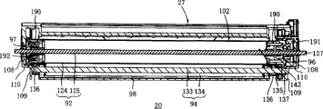
Figure 18 is the right side view of the handle box 20 shown in Fig. 3. Figure 19 is the front side view of the handle box 20 shown in Fig. 3. Figure 22 is that the bulging box 27 shown in Figure 11 is along the cross-sectional view of width.
Such as Figure 18, shown in 19 and 22, the rear side wall portion 105R of right side wall 97 can be integrally and the first wall 108R, and the second wall 109R and the 3rd wall 110R are set together. In an embodiment, such as Figure 17, shown in 18 and 19, the first wall 108R shape of the rear side wall portion 105R of right side wall 97 is different from the shape of the first wall 108L of the rear side wall portion 105L of left side wall 96.
And the shape of the second wall 109R of the rear side wall portion 105R of right side wall 97 corresponds essentially to the whole shape of the 6th wall 113 bottoms of the rear side wall portion 105L of the second wall 109L of rear side wall portion 105L of left side wall 96 and left side wall 96. The 3rd wall 110R of the rear side wall portion 105R of right side wall 97 links together the second wall 109R top of the rear side wall portion 105R of the bottom of the first wall 108R of the rear side wall portion 105R of right side wall 97 and right side wall 97.
Figure 11 and 12 has shown the 106L of front side wall section of left side wall 96 and right side wall 97,106R can comprise an axle guiding section 115, and this axle guiding section 115 is used for developer box 28 being attached to bulging box 27 or guiding respectively left end and the right-hand member of development roll shaft 64 during from 27 dismounting of drum box. Can be provided with a developer roll axle receptacle 116 in the rear end of axle guiding section 115, when developer box 28 was attached on the bulging box 27, this developer roll axle receptacle 116 can be used as for stopping or control member by development roll shaft 64 ends that guide along axle guiding section 115.
Developer roll axle receptacle 116 can form the notch by the basic side direction U-shaped that forms to upper process and with the equitant protruding wall 117 in rear portion of each left and right sides sidewall 96,97 axle guiding section 115 a little from the top of rear side wall portion 105R and 105L.
As shown in Figure 12, in an embodiment, the left side wall 96 of drum box housing 91 and the extension wall 107L of section of right side wall 97,107R can with separately left side wall 96 and the 106L of front side wall section of right side wall 97,106R forms and continuously on the phase isoplanar.
Shown in Figure 11 and 15, can arrange bulging box housing 91 diapire 98 so that its substantially be clipped between the bottom of each left and right sides sidewall 96 and 97. Diapire 98 can comprise rear bottom wall portion 193, and wall section 195 is extended at front bottom wall portion 194 and the end.
Rear bottom wall portion 193 can be for example links together the bottom of the second wall 109R of the bottom of the second wall 109L of left side wall 96 and right side wall 97. In an exemplary embodiment, rear bottom wall portion 193 is substantially V-shaped.
Rear bottom wall portion 193, but front bottom wall portion 194 and end extension wall section 195 one link together. Extend between the extension wall 107R of section of the extension wall 107L of section that wall section 195 can be clipped in left side wall 96 basically and right side wall 97 at the end. Front bottom wall portion 194 can be clipped in the 106L of front side wall section of left side wall 96 and right side wall 97 basically, between the 106R.
In certain embodiments, lower front side wall 99 can have the notch 119 that is formed on wherein, and the end extends that whole width that wall section 195 can cross downward-extension section 104 substantially and length are extended so that look from the bottom of drum box 27 and can not see notch 119.
In other embodiment, the form that can there be multilayer in wall section 195 is extended at the end, comprises the ground floor 195A integrally formed with front bottom wall portion 194, and can be attached with ground floor 195A and the second layer 195B that separates. In this case, the ground floor 195A that wall section 195 is extended at the end can have the notch 119 that is formed among the ground floor 195A, and the alongst extension of notch 119 front ends from upper alignment roller 14 front sides to ground floor 195A of second layer 195B, and at least a portion of crossing width and the ground floor 195A of notch 119 along width. Second layer 195B can with ground floor 195A attached with separate.
As shown in figure 12, the left and right sides of lower front side wall 99 can form with left and right sides sidewall 96 and 97 respectively continuously. Shown in Figure 13, when developer box 28 is attached on the bulging box 27. Lower front side wall 99 and upper front side wall 42 are aimed at above-below direction. In an embodiment, the front surface of lower front side wall 99 has dull and stereotyped shape.
As shown in Figure 13, when developer box 28 and drum box 27 were attached, notch 119 can be arranged in the lower front side wall 99 of bulging box housing 91 position corresponding to the part of the notch 80 in the upper front side wall 42 of developer box housing 29. In an exemplary embodiment, as shown in Figure 12, notch 119 shapes are substantially rectangular. When developer box 28 and drum box 27 are attached, the opening that has been combined to form a basic rectangle of the notch 119 in the notch 80 in the upper front side wall 42 and the lower front side wall 99.
As shown in figure 12, end can form receptacle 120 about lower front side wall 99. The receptacle 120 of lower front side wall 99 is admitted from each protruding member 51 of upper front side wall 42 projections of developer box housing 29, and is as described below. In an embodiment, each receptacle 120 by in the lower front side wall 99 forward the projection concave part limit.
As shown in Figure 12 and 13, when developer box 28 and drum box 27 were attached, outstanding member 51 can be admitted by corresponding receptacle 120.
Turn to now the rear portion of bulging box 27, as shown in figure 11, thereby drum box 27 can comprise along width and extends the upper rear wall 100 that can be connected with left and right sides sidewall 96,97 rear side wall portion 105L separately, 105R. Upper rear wall 100 has the basic dull and stereotyped shape that is, and tilts so that the front end of upper rear wall 100 is higher than the rear end with respect to horizontal direction.
Upper rear wall 100 can comprise the laser entrance window 121 of a basic rectangular shape that extends at drum box 27 widths in its front portion. The charger supporting member 122 that supports charger 93 can be set on upper rear wall 100, and support the brush supporting member 123 of cleaning brush 95.
As shown in FIG. 11 and 12, rousing the rear bottom wall portion 193 that box housing 91, left and right sides sidewall 96,97 each rear side wall portion 105L, 105R be connected with diapire by upper rear wall 100 connects. Rear bottom wall portion 193 can be arranged on the above-below direction fundamental sum rear wall 100 opposite faces to limit at least a portion drum accommodation section 102.
Left and right sides sidewall 96,97 the 106L of each front side wall section, 106R form developer box accommodation section 103 with the front bottom wall portion 194 of diapire 98. Developer box accommodation section 103 can be substantially disposed in the centre of bulging box housing 91. In an embodiment, developer box accommodation section 103 is open in its top side, can it is attached at drum box 27 by developer box 28 being put into developer box accommodation section 103.
As mentioned above, rouse box housing 91 and comprise downward-extension section 104. Downward-extension section 104 can extend from the front side of developer box accommodation section 103, and drum accommodation section 102 can be extended from the rear side of developer box accommodation section 103. The extension wall 107L of section of left side wall 96, the extension wall 107R of section of right side wall 97, wall section 195 is extended at the end of diapire 98, and lower front side wall 99 consists of downward-extension section 104 together.
As shown in FIG. 11 and 12, bottom extension 104 defines the space that extends to bulging box housing 91 front sides from developer box accommodation section 103. In an embodiment, downward-extension section 104 is continuous with developer box accommodation section 103, and the top side of downward-extension section 104 is open.
As shown in Figure 11, front bottom wall portion 194 can comprise First 194A and second 194B, is arranged to step-like. Opening 332 is formed between First 194A and second 194B, and paper 3 can enter and passes through from this opening. The upper surface 194D of second 194B tilts with respect to First 194A. And the upper surface 194D of second 194B can comprise the plate portion 331 of the inclination foremost that is positioned at second 194B, even more tilts with respect to First 194A.
As shown in figure 12, the upper surface 194D of second 194B can comprise a plurality of paper guiding rib 194C. Paper guiding rib 194C can extend substantially in the longitudinal direction and adjacent paper guiding rib 194C between have the interval.
And as shown in Figure 12, in certain embodiments, paper guiding film 333 is arranged at the rearward end of inclination board 331. As shown in Figure 12, paper guiding film 333 can be set to for example two parts, and these two parts are clipped in the middle in the zone that the center of inclination board 331 rearward end will have predetermined width. By paper guiding film 333 is set, the paper 3 that enters bulging box 27 from opening 332 can guide film 333 to advance along paper, the external peripheral surface of the front end contact photosensitive drums 92 of paper 3. The front end of paper 3 is directed to based on being rotated between photosensitive drums 92 and the transfer roll 94 of photosensitive drums 92. By the paper 3 that after paper 3 contact photosensitive drums 92, between photosensitive drums 92 and transfer roll 94, leads, reduced the possibility that preferably can get rid of 92 chargings of paper 3 negative effect photosensitive drums.
As shown in figure 11, photosensitive drums 92 is arranged in the bulging accommodation section 102. Photosensitive drums 92 has the shape of cylinder and comprises the bulging body 124 that can be made of the photosensitive layer of forward charging, and the bulging axle 125 that can be made of metal. The outermost surface of photosensitive drums 92 can be made of polycarbonate.
In an exemplary embodiment, rousing axle 125 and drum body 124 extends at the width of drum box 27. As shown in Figure 22, rousing axle 125 extends along the axle center of drum body 124.
As shown in Figure 14 and 17, the left end of drum axle 125 is outstanding from the first wall 108L of left side wall 96. The outermost surface 125A of the left part 125B of drum axle 125 is as earth electrode 127. Earth electrode 127 is arranged at earth electrode contact site 171 in the main casing 2 as an Electrifier frame, photoreceptor electrode contact.
In addition, can link to each other to rotate with drum body 124 one with the left end of drum body 124 around the photosensitive drum driving gear 191 of drum axle 125 rotations. That is to say that photosensitive drum driving gear 191 can not be with respect to 124 rotations of drum body. Reach as mentioned above shown in Figure 14, photosensitive drum driving gear 191 exposes from photosensitive drum gear opening 196.
In an exemplary embodiment, Compress Spring 192 is arranged on the right-hand member of bulging body 124. On drum body 124 right-hand members, Compress Spring 192 can be arranged between right side wall and the rotary support member 190. Compress Spring 192 can cause frictional resistance, and applying for the rotation that stops drum driving gear 191 of frictional resistance prevents preferably that to reduce drum body 124 from excessively rotating.
As shown in figure 11, charger 93 is arranged in the bulging accommodation section 102 and is recharged device supporting member 122 and supports. Charger supporting member 122 can be arranged on the upper rear side of photosensitive drums 92. As mentioned above, charger 93 can arrange along upper rear wall 100. Charger 93 separates with photosensitive drums 93 and does not contact photosensitive drums 92. Charger 93 comprises charging wire 128, grid 129 and charging wire cleaner 130.
In drum accommodation section 102, also can be provided with transfer roll 94 in photosensitive drums 92 belows. Transfer roll 94 can comprise the transfer printing roll shaft 133 that is made of metal, and the roll body 134 of being made by ionic conduction rubber and cover at least the part of transfer printing roll shaft 133 outer circumference.
Figure 23 (a), 23 (b) and 23 (c) have described the left end of the transfer roll 94 of the box 27 of drum shown in Figure 11. More specifically, Figure 23 (a) has described the cross-sectional view on the width, Figure 23 (b) has described the perspective view that transfer printing electrode 137 is being attached to the situation on the bulging box 27, and 23 (c) have then described the perspective view of transfer printing electrode 137 with drum box 27 attached places.
Shown in Figure 23 (a), at the left end of transfer printing roll shaft 133 a transfer roll driven wheel 135 can be set. Transfer roll driven wheel 135 can not rotate with respect to transfer printing roll shaft 133 in an embodiment. Two ends, the left and right sides at transfer printing roll shaft 133 all can be provided with bearing member 136. A bearing member 136 can be arranged to inboard adjacent with transfer roll driven wheel 135. Bearing member 136 can rotate with respect to transfer printing roll shaft 133 and transfer roll driven wheel 135. The bearing supporting member 144 that each bearing member 136 can be arranged on bulging box housing 91 diapires 98 supports.
As shown in Figure 23 (b) and 23 (c), transfer printing electrode 137 can be made by the electroconductive resin material, and integral body comprises engagement member 139, protuberance 140 and electrode contact section 141. Electrode contact section 141 can leave the basic central part of engagement member 139 inner surfaces and give prominence to. In Figure 23 (a), electrode contact section 141 is outstanding from the inner surface of engagement member 139. Transfer printing electrode 137 is by the end surfaces of electrode contact section 141 contact transfer printing roll shafts, 133 left parts. Engagement member 139 can be the tabular component that supports protuberance 140.
In certain embodiments, engagement member 139 can consist of with protuberance 140 one. In an embodiment, as shown in figure 15, transfer printing electrode opening 142 is continuous openings that partly formed by the basic Rectangle Resection on each second wall 109L, the 3rd wall 110L of left side wall 96. More specifically, shown in Figure 23 (b)-(c), cut-out on the 3rd wall 110L can be for example less than the cut-out on the second wall 109L but less times greater than protuberance 140, thereby protuberance 140 does not contact with the 3rd wall 110L when transfer printing electrode 137 is attached on the bulging box housing 91. Cut-out on the second wall 109L defines transfer printing electrode maintaining part 138.
The transfer printing electrode maintaining part 138 of drum box housing 91 comprises the transfer printing electrode receptacle 143 as receiving portion, in order to admit transfer printing electrode 137 in transfer printing electrode opening 142. In an embodiment, transfer printing electrode receptacle 143 is admitted engagement member 139. More specifically, in an embodiment, for attached transfer printing electrode 137, transfer printing electrode 137 is from drum box housing 91 inboard insertions, and importing transfer printing electrode maintaining part 138, and wherein transfer printing electrode 137 engages with transfer printing electrode receptacle 143, and the below has discussion.
As shown in figure 15, the shape and size of transfer printing electrode opening 142 formation make protuberance 140 pass the 3rd wall 110L when transfer printing electrode 137 is inserted into the transfer printing electrode maintaining part 138 of the second wall 109L.
And, when transfer printing electrode 137 was transferred electrode receptacle 143 joint, the transfer printing electrode opening kept open state, because as mentioned above, when transfer printing electrode 137 was attached on the bulging box housing 91, transfer printing electrode opening 142 was configured to allow protuberance 140 by the 3rd wall 440L. After protuberance 140 passed through the 3rd wall 110L, transfer printing electrode opening 142 was in open state (that is, not being covered).
Transfer printing electrode receptacle 143 can comprise for example two engage ribs 145, is positioned on transfer printing electrode opening section 142 every sides to face with each other. An engage ribs can be arranged on the front side of transfer printing electrode opening 142, and another engage ribs 145 can be arranged on the rear side of transfer printing electrode opening 142.
As Figure 23 (b) (c) shown in, each engage ribs 145 can comprise in the rib end ratchet 147. Ratchet 147 has the shape of hook. Ratchet 147 helps transfer printing electrode 137 is fixed in the transfer printing electrode receptacle 143 so that transfer printing electrode 137 can not slide or shift out transfer printing electrode receptacle 143.
In an exemplary embodiment, as described below, transfer printing electrode 137 is arranged in the transfer printing electrode maintaining part 138. As shown in Figure 23 (b), at first, by mobile engagement member 139 on the direction that is basically perpendicular to the 3rd wall 110L, will comprise that the engagement member 139 of protuberance 140 is positioned transfer printing electrode receptacle 143 places of drum box housing 91.
When engagement member 139 is arranged in the transfer printing electrode receptacle 143, protuberance 140 with the width of the second wall 109L quadrature on outstanding from transfer printing electrode opening 142. Then an end of engagement member 139 engages with the ratchet section 147 of a corresponding engage ribs 145. Then, shown in Figure 23 (c), engagement member 139 rotates so that the other end of engagement member 139 engages with the ratchet section 147 of another engage ribs 145.
When transfer printing electrode 137 is transferred 143 admittances of electrode receptacle and remains in transfer printing electrode maintaining part 138, protuberance 140 is outwards outstanding from transfer printing electrode opening 142 on width, can be engaged in by engagement member 139 like this and control the rotation that preferably prevents engagement member 139 in the engage ribs 145.
Shown in Figure 23 (a), when transfer printing electrode 137 is transferred 143 admittance of electrode receptacle, the end face of transfer printing roll shaft 33 left ends and 141 sliding-contacts of electrode contact section. Under this state, transfer roll driven wheel 135 is provided between the outer surface of transfer roll driven wheel 135 and the second wall 109L at axially (width) has a gap so that transfer roll driven wheel 135 can rotate freely in drum box housing 91.
As shown in Figure 11, cleaning brush 95 can be positioned to support in the drum accommodation section 102 and by brush supporting member 123. Brush supporting member 123 can be arranged on the upper rear wall 100 at the bulging box housing 91 left and right sides places after the photosensitive drums 92.
Cleaning brush 95 comprises many bristles, and bristle is planted on the holding plate of the basic rectangular strip that extends with width. Cleaning brush 95 is in the longitudinal direction in the face of photosensitive drums 92 location that lies low. Bristle contacts to clean the photosensitive drums external peripheral surface with the external peripheral surface of photosensitive drums 92. Cleaning electrode 148 is made of for example sheet metal member, and links to each other with the brush supporting member 123 in left side. Cleaning electrode 148 is fixed on the brush supporting member 123 so that this electrode is outstanding from the left side of drum box 27. In an embodiment, shown in Figure 14 and 17, cleaning electrode 148 is outstanding from the basic vertical slits on the 6th wall 113 that is formed on left side wall 96.
As mentioned above, in developer box accommodation section 103, protuberance 118 can be set. In an embodiment, each protuberance 118 contacts with one of them align member 84 of developer box 28. As shown in Figure 12, in an embodiment, there is the interval along width between two protuberances 118. Two protuberances 118 are arranged on the front bottom wall portion 194. As shown in Figure 3, when developer box 28 and drum box 27 were attached, each protuberance 118 was towards one of them align member 84 of developer box 28. Each protuberance 118 is the convex surface shape that substantially raises up.
In certain embodiments, protuberance 118 can be arranged on that align member 84 then is arranged on the bulging box 27 on the developer box 28.
As shown in Figure 15, the end rib 162 as the leader that guides paper 3 also is arranged in the developer box accommodation section 103. The end rib 162 in the past bottom surface of bottom wall portion 194 is given prominence to downwards. End rib 162 can comprise rib 163 of a plurality of rear ends and rib of a plurality of middle ends 164.
Rib of the rear end 163 extends substantially in the longitudinal direction. Between rib of the rear end 163 adjacent on the width, there is the gap. Rib of a plurality of middle ends 164 can be positioned to than rib of the rear end 163 more also can substantially alongst extend towards the front portion. Between rib of the middle end 164 adjacent on the width, there is the gap.
As shown in Figure 12, in developer box accommodation section 103, toner is surveyed opening 101 and is arranged on the part that each left side wall 96 and right side wall 97 face, and light can be surveyed opening 101 by toner by/empty sensor 371 low from developer. As mentioned above, toner detection opening 101 is positioned at the left side wall 38 of developer box 28 and the position on the right side wall 39 in each left side wall 96 and the position on the right side wall 97 of drum box 27 corresponding to toner detecting window 85.
Each toner detecting window 85 is aligned with each other so that the light that launches from a side can pass every group of toner detection window and/or opening 85,101 with at least a portion of toner detection opening 101 like this, and is detected at opposite side when the toner amount is lower than predetermined value at least.
As mentioned above, in certain embodiments, when developer low/when empty sensor 371 determined that the toner amounts are lower than scheduled volume, imaging device can provide an expression toner amount with sky or measure low signal and/or quit work, until the toner amount is added.
Even when the toner amount was higher than predetermined value/level, some light that launch from a side can pass toner detecting window and/or opening 85,101 and received at opposite side. Like this, if opposite side detects the light more than scheduled volume, the toner developer is low/empty sensor 371 can be configured to trigger toner low/spacing wave.
As shown in Figure 12, downward-extension section 104 can comprise that a pressurization part 149 and a bulging box protrude 150. The drum box protrudes 150 can help to guide and arrange bulging box 27 and/or handle box 20 in the main casing 2 of laser printer 1. In drum box 27, the drum box protrudes the 150 extension wall 107L of section from each left side wall 96 and right side wall 97, and 107R is outstanding.
Shown in Figure 12 and 17, the drum box protrudes 150 and can be cylindric, and can be arranged to respectively from left and right sides sidewall 96,97 the extension wall 107L of section, 107R outstanding. The drum box protrudes 150 can be outwards outstanding from the outer surface difference of the lower front portion of the extension wall 107L of section, 107R along width
When the developer box accommodation section 103 of developer box 28 and drum box 27 was attached, pressurization part 149 helped developer roll 32 is pressed to photosensitive drums 92. In the embodiment shown in Figure 12, at each left and right sides place of downward-extension section 104 pressurization part 149 is set.
A pressurization part 149 can be set in certain embodiments, a plurality of pressurization part 149 then can be set among other embodiment. Also have, in comprising more than the embodiment of a pressurization part 149, dissimilar pressurization part 149 can be set. In certain embodiments, can be provided as the locking lever 153 of locking device, be used for behind the developer accommodation section 103 that developer box 28 is attached to bulging box 27, developer box 28 being locked or be fixed on bulging box 27. In certain embodiments, by pressing and/or spur locking lever 153 developer box 28 is discharged from drum box 27.
Figure 21 (a), 21 (b), 21 (c) and 21 (d) consist of developer box 28 shown in setting/attached Fig. 4 in the box 27 of drum shown in Figure 11, to form the overall procedure chart of the handle box 20 shown in Fig. 3. In the embodiment shown in Figure 21, extension 86 is covered in demonstration.
Figure 21 (a) has shown that developer box protrusion 79 is positioned at the state of pressurization part 149 upsides. Figure 21 (b) has shown that the developer box protrudes 79 states that contact with the guiding surface 154 of pressurization part 149. Figure 21 (c) has shown that the developer box protrudes 79 states that contact with guiding surface 154 and the border between the fixed surface 155 of pressurization part 149. Figure 21 (d) has shown that the developer box protrudes 79 states that just contacting with the fixed surface 155 of pressurization part 149.
As shown in Figure 21 (a)-(d), each pressurization part 149 can be furnished with a pressing element 151, when the developer box 28 attached/be arranged in the bulging box 27 and from drum box 27 separately the time, pressing element 151 can engage and contact separately developer box protrusion 79 with being disengaged. Spring 152 as thrust unit can be arranged at each pressing element 151 belows, pressing element 151 is upwards pressed developer box corresponding on the left and right sides of bulging box 27 and protrudes 79.
Guiding surface 154 can be downward-sloping, and like this, the front portion of guiding surface 154 is positioned on the level that is higher than guiding surface 154 rear portions. Fixed surface 155 is downwards basic and from front side-prominent towards drum box 27 of guiding surface 154. Like this, the guiding surface of pressing element 151 154 is downwards basic and extend back, and fixed surface 155 is downwards basic and extend forward, so guiding surface 154 and fixed surface 155 have formed an obtuse angle. Guiding surface 154 and fixed surface 155 are all towards drum box housing 91 rear portions.
One end of each spring 152 can be fixed on the lower front portion of end extension wall section 195. As mentioned above, each spring 152 other ends can be engaged by the bottom surface of pressing element 151 or be pressed against on the bottom surface of pressing means 151. As shown in Figure 21 (a)-21 (d), in an exemplary embodiment, in the different conditions of attached/separation process, because the power that spring 152 applies and spring 152 setting in drum box housing 91, corresponding pressing element 151 is pushed to keep the state of inclination, and spring 152 is than the front portion of the more close drum box 27 of pressing element 151 like this.
As shown in figure 13, locking lever 153 can be arranged on the left end of downward-extension section 104. Locking lever 153 can be arranged near pressing element 151. Locking lever 153 can have a base portion, two legs is outwards outstanding from base portion, wherein one leg is from this vertically extending elastic component 159 of base portion one end group, and one leg then is to leave the control member 158 that the base portion other end extends along diagonal substantially in addition.
The base portion of locking lever 153 can form a contact developer box protrusion 79 and the developer box is protruded 79 " lockings " to the contact site 161 of appropriate location. One side of contact site 161 is can be along width to the developer box 28 interior outstanding so that a surface to be provided, the developer box protrude 79 the inferior horn around contact site 161 slide and the opposite side locking that is touched section 161 as described below before slide on above-mentioned surface. As shown in figure 18, when the protrusion of the developer box on the left side wall 96 of developer box housing 28 79 was locked on the appropriate location, the developer box on the right side wall 97 protruded 79 and can be arranged in the groove 16 of bulging box housing 91. Groove 16 can be substantially disposed in the top of the upper alignment roller 14 on the right side wall 97 of bulging box housing 91.
In an exemplary embodiment, when developer box 28 is in the attached state of rousing box 27 or released state, the end that is attached at the elastic component 159 on locking lever 153 base portions is generally than the control member 158 of the more close locking lever 153 of the other end of elastic component 159, control piece 158 generally keeps basic horizontal at the length direction of drum box 27, such as Figure 21 (a), shown in 21 (b) and 21 (d). That is to say that because the elastic force of elastic component 159, locking lever 153 generally is location like this, so that the end face of control piece 158 aims at substantially with upper wall extension 50, shown in Figure 13 and 19.
As shown in Figure 21 (c), in an exemplary embodiment, when corresponding developer box protrudes 79 when being directed around the border between locking lever 153 and the elastic component 159, elastic component 159 bendings or deflection are so that an end that is connected with locking lever 153 base portions on the elastic component 159 moves to more close control member 158 and spurs control member 158, and developer box protrusion 79 can be arranged on contact site 161 belows (seeing Figure 21 (d)) of locking lever 153 like this.
Shown in Figure 21 (d), when developer box protrusion 79 is arranged on contact site 161 below, as the result of the pressure of the photosensitive drums 92 of developer box 28 being pressed to backward bulging box 27 of spring 152, pressurization part 149 assists in ensuring that developer roll 32 contacts with photosensitive drums 92.
As shown in Figure 15, upper alignment roller 14 and/or rib of the front end 165 can be along the outer bottom settings of downward-extension section 104. As mentioned above, upper alignment roller 14 can be used for paper 3 is passed to photosensitive drums 92. Upper alignment roller 14 can be arranged at the front end place of rib of the middle end 164 rotatably, goes up like this bottom surface of extending wall section 195 in the 14 basic ends along diapire 98 of alignment roller and extends at width. Upper alignment roller 14 rotates around axle 14A.
In an exemplary embodiment, upper alignment roller 14 is positioned between the rib of the front end 165 and end rib 162 on the width. As shown in Figure 1, when drum box 27 was attached on the main casing 2, upper alignment roller 14 was positioned in above the above-below direction towards lower alignment roller 14.
Set rib of the front end 165 can help to guide paper 3 by laser printer 1. As shown in Figure 15, front end rib 165 is can be from the bottom surface of downward-extension section 104 outstanding and substantially extend at length direction downwards. On the width, there is the gap between the adjacent rib of the front end 165. Rib of the front end 165 can be arranged at the front side of alignment roller 14. As shown in Figure 15, front end rib 165 can be arranged to stride across width.
In certain embodiments, notch 119 is formed on end extension wall section 195 and the lower front side wall 99, and as mentioned above, extend wall section 195 and can comprise ground floor 195A and second layer 195B at the end. In this case, end rib 165 before the outer bottom place that strides across the end and extend the second layer 195B of wall section 195 can arrange, the overlapped so that paper 3 of second layer 195B and notch 119 can more effectively be guided.
In certain embodiments, rib of the front end 165 is made by the material that is different from the material of making drum box housing 91. For example, rib of the front end 165 can be made by the material harder than the material that is used to form bulging box housing 91, can help like this to reduce the infringement that preferably prevents rib of the front end 165. As mentioned above, if drum box housing 91 usefulness resin materials (such as, polystyrene) are made, 165 in rib of the front end is made by poly-acetal resin. As mentioned above, extend wall section 195 end of at and comprise that in the situation of ground floor 195A and second layer 195B, ground floor 195A can be made by the material that is same as bulging box housing 91, and second layer 195B is made by a kind of harder material.
In certain embodiments, the gap between each rib of front end 165, rib of the middle end 164, rib of the rear end 163 can be arranged to improve to the guiding of paper by laser printer 1. In an embodiment, any two or rib of the more front end 165, rib of the middle end 164, rib 163 of the rear end gap that between corresponding adjacent rib, can have basic identical size. Also have, in certain embodiments, any two or rib of the more front end 165, rib of the middle end 164, rib 163 of the rear end can have the gap of different size between corresponding adjacent rib. In certain embodiments, rib of the front end 165, rib of the middle end 164 can be aimed at length direction.
When the developer box protrude 79 with pressurization part 149 attached/separate when helping to guarantee when developer box 28 and bulging box 27 are attached contacting between the developer roll 32 and photosensitive drums 92, developer box 28 with drum box 27 attached and separate during, other parts of bulging box 27 can engage with other parts of developer box 28.
Shown in Figure 17,18,20, the two ends, the left and right sides of development roll shaft 64 are projected into outside the left and right sides sidewall 96,97 axle guiding section 115 of bulging box housing 91 at width. More specifically, when developer box 28 is received within developer box accommodation section 103, the ring element 83 that two ends, development roll shaft 64 left and right sides arrange outwards is being projected on the width outside each left and right sides sidewall 96 of bulging box housing 91,97 the axle guiding section 115, and the rear side of ring element 83 contacts with the rear end of developer roll axle receptacle 116.
As mentioned above, when developer box 28 was arranged in the developer box accommodation section 103, developer roll 32 contacted with photosensitive drums 92. Below concrete discuss developer box 28 and drum box 27 attached/process of separating.
A pressurization part 149 only is set in an exemplary embodiment. A plurality of pressurization part 149 then can be set in certain embodiments. Shown in Figure 21 (a), for developer box 28 being attached on the bulging box 27, developer box 28 can be positioned at 103 tops, developer box accommodation section of bulging box 27 so that left developer box protrusion 79 is positioned at the upside of pressurization part 149, and the two ends, the left and right sides of development roll shaft 64 are arranged in the axle guiding section 115 of corresponding bulging box 27.
As shown in Figure 21 (b), in an exemplary embodiment, when developer box 28 gradually when pressing down, each developer box protrudes 79 and moves down, and left developer box protrudes 79 guiding surfaces 154 at pressing element 151 and slides. The result, pressing means 151 rotates gradually around fixed axis 157, the power of the top antagonistic spring 152 of pressing means 151 moves forward like this, and the development roll shaft 64 that is being supported by corresponding axle guiding section 115 about hold and further slide towards developer roll axle receptacle 116.
Next, such as Figure 21 (c) when left developer box protrudes the guiding surface 154 of 79 contact pressing means 149 and the border between the fixed surface 155, the left developer box that contacts corresponding contact site 161 protrude 79 continue to move down locking lever 153 then the elastic force of resistance elastic component 159 around retainer shaft 160 rotations. Control piece 158 is moved down into more close elastic component 159.
Equally, as shown in Figure 21 (c), when developer roll 32 contact photosensitive drums 92, the ring element 83 that is arranged at development roll shaft about 64 ends is received in the corresponding developer roll axle receptacle 116 (seeing Figure 17). Left developer box protrudes 79 and arrives the guiding surface 154 of pressing means 149 and the border between the fixed surface 155.
After this, because the leading section of developer box 28 further reduces, the developer box protrudes 79 and passes between the contact site 161 of pressing means 151 and locking lever 153. Shown in Figure 21 (d), the developer box that is clipped between the edge of the stationary plane 155 of pressing means 151 and contact site 161 protrudes 79, before on the position between another edge of the stationary plane 155 that is " locked " to locking lever 153 and contact site 161 around one jiao of slip of contact site 161.
As shown in Figure 21 (d), after left developer box protrusion 79 was " locked " to the appropriate location, control piece 158 again recovered its basic horizontal position and/or substantially aims at upper wall extension 50. In this state, the backward pressure of the pressing means 151 that is produced by spring 152 helps developer box 28 is pressed to bulging box 27, and like this, developer roll 32 is pressed against to photosensitive drums 92.
In this state, because developer box protrusion 79 is positioned corresponding contact site 161 belows of locking lever 153, thereby so contact site 161 engages with left developer box protrusion 79 developer box protrusion 79 can not be moved up, discharge the developer box unless locking lever 153 is moved downward and protrude 79.
From the state shown in Figure 21 (d) as can be known, in an exemplary embodiment, in order to remove developer box 28 from the developer box accommodation section 103 of drum box 27, the control piece 158 of locking lever 153 can be pressed downward the developer box is protruded 79 and discharge from contact site 161 belows.
When locking lever 153 was pressurized, locking lever 153 rotated around retainer shaft 160, and the developer box protrudes 79 and is released out, and rotated towards developer box 28 back because be positioned at the contact site 161 that the developer box protrudes 79 tops. When the result was upwards drawn when developer box 28, the developer box protruded 79 and freely moves up between the contact site 161 of locking lever and pressing element 151 against the backward pressure of spring 152.
After developer box protrusion 79 discharged from pressurization part 149, when pulling developer box 28, the two ends of development roll shaft 64 did not occupy corresponding developer roll axle receptacle 116, and developer box 28 can easily shift out from developer box accommodation section 103.
When developer box 28 is attached on the bulging box 27 when forming handle box 20, the various piece of developer box 28 links to each other with the corresponding part of drum box 27 or aims at.
As shown in Figure 7, the lower wall 40 of developer box housing 29 can be included in the block 341 that the left and right sides arranges. Block 341 is tabular component, and is upwards substantially vertically outstanding from the rear end of lower wall 40. As shown in Figure 12, each block 341 engages with the block receiver member 244 of drum box 27, attached with drum box 27 when developer box 28, therefore when block 341 engaged with block female part 244, developer box 28 was prevented from being moved further backward with respect to drum box 27. End arranges a block 341 about each of developer box 28, and end arranges a block female part 244 about each of drum box 27. Block 341 can help to stop developer to leak out from developer box 28 equally.
As mentioned above, when developer box 28 was attached on the bulging box 27, each keeper 84 on the developer box 28 was positioned on the corresponding protuberance 118 of bulging box 27. The downward-extension section 104 of the upper extension 37 of developer box 28 and drum box 27 aims at, so that upper extension 37 is arranged on the downward-extension section 104, as shown in figure 13.
In certain embodiments, shown in Fig. 7,8,13, on the left side wall 38 of developer box 28, a new product detector 301 can be set. U.S. Patent application No.10/891,142 have detailed description to this detector, and its disclosed subject content is incorporated by reference herein. As shown in figure 13, new product detector 301 can comprise an engagement lever 302 of outwards giving prominence to from the basic arcuate socket 303 of gear cap 77 at width. Engagement lever 302 is positioned an end (for example front end) of arcuate socket 303 when developer box 28 is a new product, and when developer box 28 is when being used for the first time, engagement lever 302 is surveyed the other end that actuator 374 (shown in Figure 25) is shifted to arcuate socket 303 by the new product of laser printer 1. According to the position of engagement lever 302, it is new or used (have and use historical product) that new product detector 301 can be surveyed developer box 28 thus.
As mentioned above, when a new developer box 28 or handle box 20 are attached in the main casing 2, engagement lever 302 (seeing Figure 13) the contact new product that is arranged at the new product detector 301 on the developer box 28 is surveyed the bottom of actuator 374, presses backward so that the bottom of new product detection actuator 374 is touched lever 302. As a result, new product is surveyed actuator 374 and is rotated counterclockwise, and determines that based on the rotation of new product detection actuator 374 developer box 28 is new products simultaneously.
On the other hand, because the engagement lever 30 of the new product detector 301 of developer box 28 is moved on to the other end by the end from arcuate socket 303, engagement lever 302 is outwards outstanding from arcuate socket 303 when a used developer box 28 is attached to main casing 2, and the engagement lever 302 of used developer box 28 is surveyed actuator 474 with new product and do not contacted. Like this, new product detection actuator does not rotate. Based on above operation, can determine that attached developer box 28 is used products.
When handle box 20 was installed in the main casing 2, the toner of drum box 27 was surveyed opening 101, and toner detecting window 85 and the developer of developer box 28 be low/and at least one part of empty sensor 371 aims at along width. In addition, the bottom of alignment roller pressing means 372 contacts the left end of the upper alignment roller 14 that processed box 20 supporting, and the left part of upper alignment roller 14 by alignment roller pressing means 372 to pressing down.
In certain embodiments, be attached on the bulging box 27 when consisting of handle box 20 gear mechanism 45 at least part of spaces that occupy between pressurization part 149 and the photosensitive drums 92 of developer box 28 when developer box 28.
Next the left side of the handle box 20 that forms when developer box 28 is attached to bulging box 27 is more specifically described. As shown in Figure 17, cleaning electrode 148, gate electrode 132, charging wire electrode 131, and transfer printing electrode 137 is arranged on the left side wall 96 of bulging box housing 91. As shown in Figure 12, earth electrode 127 can be arranged to stretch out from left side wall 96.
On the left side wall 38 of developer box housing 29, can be provided with developer roll electrode 76 so that it stretches out from developer box housing 29. When developer box 28 was attached on the bulging box 27, developer roll electrode 76 extended outwardly into outside the left side wall 96 of bulging box housing 91. Like this, in the embodiment of handle box 20, all electrodes (namely cleaning electrode 148, gate electrode 132, charging wire electrode 131, earth electrode 127, transfer printing electrode 137, developer roll electrode 76) all are positioned at the left side of handle box 20.
As mentioned above, in an exemplary embodiment, gear mechanism 45 is arranged on the left side wall 38 of developer box housing 29 equally, like this gear mechanism 45 be positioned developer box housing 29 with above-mentioned electrode (cleaning electrode 148, gate electrode 132, charging wire electrode 131, earth electrode 127, transfer printing electrode 137 and developer roll electrode 76) on the identical side.
More specifically, in certain embodiments, above-mentioned electrode and gear mechanism 45 are respectively towards the rear side setting of the left side wall 38 of the rear side of the left side wall 96 of drum box housing 91 and developer box housing 29.
Like this, in an exemplary embodiment, above-mentioned electrode and gear mechanism 45 be not separately positioned on bulging box housing 91 left side wall 96 the 106L of front side wall section and extend on the wall 107L of section, and on the left side wall extension 52 of the upper extension 37 of developer box housing 29.
For example, in the embodiment of handle box 20, all above-mentioned electrodes all are the back at the center (seeing the some C of Figure 17) that alongst is arranged on handle box 20. More specifically, in certain embodiments, input gear 68 is arranged on respect to above-mentioned electrode 148,132,131,127,137,76 foremost along the left side of handle box 20.
In an exemplary embodiment, in all above-mentioned electrodes (namely cleaning electrode 148, gate electrode 132, charging wire electrode 131, earth electrode 127, transfer printing electrode 137 and developer roll electrode 76), cleaning electrode 148 is to be arranged in rearmost electrode.
More particularly, among more aforesaid embodiment, cleaning electrode 148 is arranged on the 6th wall 113 and is the most inboard electrode in all above-mentioned electrodes at width, because gate electrode 132 and charging wire electrode 131 are arranged on the wall 111, transfer printing electrode 137 is arranged on the second wall, and earth electrode 127 and developer roll axial electrode 76 stretch out from the first wall 108L. Thus, in certain embodiments, cleaning electrode 148 is rear side and the most inboard electrodes in all above-mentioned electrodes.
As shown in Figure 14, in an exemplary embodiment, cleaning electrode 148 is arranged in more the inside along width than gear mechanism 45. In an embodiment, cleaning electrode 148 is positioned on the handle box 20 outside the imaging region X along width, and in imaging region X, image that will imaging is formed on the paper 3 that passes through between photosensitive drums 92 and the transfer roll 94.
The below will describe the relative position of above-mentioned electrode on the width of described handle box 20. As shown in figure 14, developer roll electrode 76 and earth electrode 127 outwards are projected into the first wall 108L of bulging box 27 along width, outside the 108R. As mentioned above, the 5th wall 112 extend internally from the first wall 108L top and with the wall 111 of charging wire electrode 131 with gate electrode 132 be set link to each other. Like this, in an exemplary embodiment, charging wire electrode 131 and gate electrode 132 are than developer roll electrode 76 and earth electrode 127 more inside.
Like this, in an exemplary embodiment, cleaning electrode 148, transfer printing electrode 137, charging wire electrode 131, lattice utmost point gate electrode 132, earth electrode 127 and developer roll electrode 76 are arranged on above bulging box housing 91 left side walls 96 or near it from right to left continuously. In an embodiment, electrode 148,137,131,132,127 and 76 also can be arranged on the bulging box housing 91 different point along its length.
The following describes can attached/demounting process cartridge 20 and each features of main casing 2 Relations Amongs. As mentioned above, handle box 20 is can be with main casing 2 attached or remove, as shown in Figure 2. As shown in Figure 1, when handle box 20 was attached to main casing 2, the keeper 166 on rousing box protrusion 150 and being arranged on main casing 2 engaged. Keeper 166 helps handle box 20 is positioned in the main casing 2, and therefore the front end of handle box 20 does not move down when the rear end of handle box 20 is upwards pushed away by the power of photosensitive drums 92 and developer roll 32 rotation generations. Like this, align member 166 assists in ensuring that handle box 20 correctly is arranged in the main casing 2. When external force may promote handle box 20 and the position is set removes from it, keeper 166 also can help handle box 20 to stay on main casing 2 inner its attachment locations in imaging process.
As shown in figure 24, main casing 2 can comprise the left frame 167 that is positioned at attached dress/6 left sides, dismounting chamber. The inner face offside of left frame 167 (namely facing a side in attached/dismounting chamber 6) can comprise cleaning electrode connecting portion 168, gate electrode connecting portion 169, charging wire electrode connecting portion 170, earth electrode connecting portion 171, transfer printing electrode connecting portion 172, developer roll electrode connecting portion 173. Cleaning electrode connecting portion 168, gate electrode connecting portion 169, charging wire electrode connecting portion 170, earth electrode connecting portion 171, transfer printing electrode connecting portion 172, developer roll electrode connecting portion 173 are all by being wired on the power supply that is arranged on main casing 2 inside (for example high voltage source) of not describing of not describing.
Electrode connecting portion 168,169,170,171,172 and 173 are arranged on the inner face offside of left frame 167, therefore after handle box 20 is attached on the main casing 2, cleaning electrode connecting portion 168, gate electrode connecting portion 169, charging wire electrode connecting portion 170, earth electrode connecting portion 171, transfer printing electrode connecting portion 172, developer roll electrode connecting portion 173 is facing respectively cleaning electrode 148, gate electrode 132, and charging wire electrode 131, earth electrode 127, transfer printing electrode 137 and developer roll electrode 76 also contact with it.
Each electrode connecting portion 168,169,170,171,172 and 173 helps to provide electric power to arrive corresponding electrode 148,132,131,127,137 and 76 or with electrode grounding.
Cleaning electrode connecting portion 168 can be connected by electrical wiring to power supply. Cleaning electrode connecting portion 168 is as the tie point that applies the cleaning bias voltage to cleaning electrode 148. Described cleaning bias voltage can be set in about 400 volts.
Gate electrode connecting portion 169 is connected by electrical wiring to power supply. Gate electrode connecting portion 169 is as the tie point that applies grid voltage to grid 132. Described grid voltage can be set in about 900 volts.
Charging wire electrode connecting portion 170 is connected by electrical wiring to power supply. Charging wire electrode connecting portion 170 is as the tie point that applies discharge voltage to charging wire electrode 131. Described discharge voltage can be set in about 7000 volts.
Earth electrode connecting portion 171 is connected by electrical wiring to power supply. Earth electrode connecting portion 171 is as the tie point with earth electrode 127 ground connection.
Transfer printing electrode connecting portion 172 is connected by electrical wiring to power supply. Transfer printing electrode connecting portion 172 is as the tie point that applies the transfer printing bias voltage to transfer printing electrode 137. Described transfer printing bias voltage can be set as the positive transfer printing bias voltage about maximum-6500 volt, perhaps maximum about 1600 volts reverse transfer printing bias voltage.
Above and developer roll electrode connecting portion 173 hereinafter described and developer roll shaft coupling piece 175 be connected by electrical wiring to power supply. Developer roll electrode connecting portion 173 is as the tie point that applies the development bias voltage to developer roll electrode 173. Described development bias voltage can be set in about 400 volts.
Figure 25 is the side view of inner surface of the left frame 167 of laser printer 1. Figure 26 is the side view of inner surface of the correct frame 281 of laser printer 1. Figure 27 (a) and 27 (b) have shown respectively propelling state and the retracted mode of the connecting elements 73 that can be adopted by laser printer 1.
As shown in figure 25, (namely face the surface in attached/dismounting chamber 6) on the inner surface of the left frame 167 in main casing 2 and be provided with charging wire electrode contact section 271, transfer printing electrode contact section 272, developer roll electrode contact section 273, gate electrode contact site 274, cleaning electrode contact section 275, and earth electrode contact site 276. When drum box 27 or handle box 20 are attached on the main casing 2, charging wire electrode contact section 271, transfer printing electrode contact section 272, developer roll electrode contact section 273, gate electrode contact site 274, cleaning electrode contact section 275, earth electrode contact site 276 is contact charging line electrode 131, transfer printing electrode 137 respectively, developer roll electrode 76, gate electrode 132, cleaning electrode 148, earth electrode 127.
Charging wire electrode contact section 271 can be the expose portion (shown in Figure 24) of the wire that connects together with charging wire electrode connecting portion 170. Charging wire electrode contact section 271 can be basic U font. At least the base portion of U font charging wire electrode contact section 271 is exposed and links to each other with charging wire electrode 131 when handle box 20 is attached on the main casing 2. Two arms of U font charging wire electrode contact section 271 are connected to charging wire electrode connecting portion 170, and are connected to the power supply (for example high voltage source) that does not show that is arranged on main casing 2 inside by the wiring that does not show. The base portion of U font charging wire electrode contact section 271 can extend along diagonal in the longitudinal direction, as shown in figure 25.
Transfer printing electrode contact section 272 can be the expose portion (shown in Figure 24) of the wire that connects together with transfer printing electrode connecting portion 172. Transfer printing electrode contact section 272 can be basic U font. At least the base portion of U font transfer printing electrode contact section 272 is exposed and links to each other with transfer printing electrode 137 when handle box is attached on the main casing 2. Two arms of U font transfer printing electrode contact section 272 are connected to transfer printing electrode connecting portion 172, and are connected to the power supply (for example high voltage source) that does not show that is arranged on main casing 2 inside by the wiring that does not show. As shown in figure 25, transfer printing electrode contact section 272 can be positioned at charging wire electrode contact section 271 belows, and the base portion of U font transfer printing electrode contact section 272 can essentially horizontally extend in the longitudinal direction.
Developer roll electrode contact section 273 can be the expose portion (shown in Figure 24) of the wire that connects together with developer roll electrode connecting portion 173. Developer roll electrode contact section 273 can be substantially reverse wide U font of dehiscing. As shown in figure 25, in an exemplary embodiment, the base portion of reverse wide U font developer roll electrode contact section 273 of dehiscing is exposed with arm and links to each other with developer roll electrode 76. The bottom of two arms of reverse U font developer roll electrode contact section 273 can be connected to developer roll electrode connecting portion 173, and is connected to the power supply (for example high voltage source) that does not show that is arranged on main casing 2 inside by the wiring that does not show. As shown in figure 25, developer roll electrode contact section 273 can be positioned at charging wire electrode contact section 271 and transfer printing electrode contact section 272 fronts, and developer roll electrode contact section 273 also can be positioned at transfer printing electrode contact section 272 tops and charging wire electrode contact section 271 belows.
Gate electrode contact site 274 can be the expose portion (shown in Figure 24) of the wire that connects together with gate electrode connecting portion 169. Gate electrode contact site 274 can be basic U font. At least the base portion of U font gate electrode contact site 274 is exposed and links to each other with gate electrode 132. Two arms of U font gate electrode contact site 274 are connected to gate electrode connecting portion 169, and are connected to the power supply (for example high voltage source) that does not show that is arranged on main casing 2 inside by the wiring that does not show. As shown in figure 25, gate electrode contact site 274 can be positioned at charging wire electrode contact section 271 and transfer printing electrode contact section 272 back, and gate electrode contact site 274 can be positioned at transfer printing electrode contact section 272 tops or charging wire electrode contact section 271 belows. Gate electrode contact site 274 can be positioned to than close transfer printing electrode contact section 272 more near charging wire electrode contact sections 271. The base portion of U font gate electrode contact site 274 can extend along diagonal in the longitudinal direction, as shown in figure 25.
Cleaning electrode contact section 275 can be the expose portion (shown in Figure 24) of the wire that connects together with cleaning electrode connecting portion 169. Cleaning electrode contact section 275 can be basic U font. At least the base portion of U font cleaning electrode contact section 275 is exposed and links to each other with cleaning electrode 132. Two arms of U font cleaning electrode contact section 275 are connected to cleaning electrode connecting portion 169, and are connected to the power supply (for example high voltage source) that does not show that is arranged on main casing 2 inside by the wiring that does not show. As shown in figure 25, cleaning electrode contact section 275 can be positioned at charging wire electrode contact section 271 and transfer printing electrode contact section 272 back. Cleaning electrode contact section 275 can be positioned at transfer printing electrode contact section 272 tops or charging wire electrode contact section 271 belows. Cleaning electrode contact section 275 can be positioned to than 271 more close transfer printing electrode contact sections 272 of close charging wire electrode contact section. The base portion of U font cleaning electrode contact section 275 can extend along diagonal in the longitudinal direction, as shown in figure 25.
As shown in figure 25, the earth electrode contact site 276 that earth electrode 127 is in contact with it after handle box 20 is attached on the main casing 2 can be arranged on the inner surface of left frame 167. Earth electrode contact site 276 can form by wire is curved fundamental triangle, as shown in figure 25.
Earth electrode contact site 276 can comprise one upwards crimping ground electrode contact site 276 so that its pressing element (not shown) such as spring that engages with earth electrode receptacle 323 (below tell about). In an exemplary embodiment, earth electrode contact site 276 is by earth electrode connecting portion 171 and left frame 167 link together (seeing Figure 24).
Earth electrode contact site 276 can be positioned at transfer printing electrode contact section 272 tops or charging wire electrode contact section 271 belows. The electric wire that forms earth electrode contact site 276 is connected to earth electrode connecting portion 171 with earth electrode contact site 276, and the power supply (for example earthing power supply) that is arranged on main casing 2 inside by being wired to of not describing or the metal part of main casing 2.
For example, the connecting elements 73 that is used for the driving force of input driving input gear 28 is arranged on the top, front side of developer roll electrode contact section 273 on left frame 167 inner surfaces movably, and aims in the longitudinal direction with charging wire electrode contact section 271.
Inner surface in left frame 167 is provided with a drum gear 321, and drum gear 321 is meshed with the photosensitive drum driving gear 191 (seeing Figure 37 and 38) of bulging box 27 and/or handle box 20 when drum box 27 and/or handle box 20 are attached on the main casing 2. Drum gear 321 can be arranged on transfer printing electrode contact section 272 and earth electrode contact site 276 back, perhaps gate electrode contact site 274 belows.
Also have, inner surface in left frame 167, the developer with dummy status that be used for to survey the toner in the developer accommodation section 30 that is included in developer box 28 is low/and empty sensor 371 can be positioned at developer roll electrode contact section 273 fronts, thereby when handle box 20 was attached in the main casing 2, developer was low/and empty sensor 371 aims at the toner detecting window 101 on the left and right sides sidewall 96,97 that is formed on bulging box housing 91 at width. Developer is low/and empty sensor 371 can comprise a photocell that is arranged on one of left frame 167 or correct frame 281, and a light receiving element that arranges on another of left frame 167 or correct frame 281.
In addition, developer low/empty sensor 371 fronts are provided with alignment roller pressing element 372. When handle box was attached on the main casing 2, alignment roller pressing means 372 pressed the left end of alignment roller 14 downwards. Alignment roller pressing means 372 can be formed by the torque spring that is supported by axle 372. Alignment roller pressing element 372 is can be along width from left frame 167 inwardly outstanding.
As shown in Figure 25, alignment roller pressing means 372 can be arranged to the diagonal ground that makes progress, the front side of an end along electrode guiding surface 322 (back has description) towards laser printer 1 and extend, and its other end then extends towards downward diagonal ground, the front side of laser printer 1.
In addition, survey actuator 374 left sides or the right side is observed from new product, the new product of V-shape survey actuator 374 be positioned at developer low/empty sensor 371 and alignment roller pressing means 372 tops and between the two. New product is surveyed actuator 374 and is rotatably supported by the axle 375 of 167 inwardly projectings along width from left frame. The end portion of new product detection actuator 374 can constantly be pushed by spring (without diagram) front side of laser printer 1 to.
In certain embodiments, left frame 167 can comprise electrode guiding surface 322. During the attached and dismounting, set electrode guiding surface 322 helps guiding earth electrode 127 and developer roll electrodes 76 at handle box 20. Alongst 323 extensions from main casing 2 front portions to the earth electrode receptacle of electrode guiding surface 322. Earth electrode receptacle 322 can be arranged near earth electrode contact site 276.
When handle box 20 was attached in the main casing 2, earth electrode 127 and developer roll electrode 76 slided along the surface of electrode guiding surface 322, until earth electrode 127 is engaged by earth electrode receptacle 323. Earth electrode receptacle 323 can be a slotted section that is U word shape, is configured to the opening surface of earth electrode receptacle 323 of U font to the front portion of laser printer 1.
When being attached to handle box 20 on the main casing 2, earth electrode 127 is directed into electrode guiding surface 322, admits until it is grounded electrode receptacle 323. Before arriving earth electrode receptacle 323, earth electrode connecting portion 171 is to pressing down from developer roll electrode contact section 273 that electrode guiding surface 322 projects upwards so that it walks around earth electrode contact site 273. Then earth electrode connecting portion 171 is towards electrode guiding surface 322 downward crimping ground electrode contact sites 276.
When earth electrode 127 was grounded electrode receptacle 323 and admits, the pressing means (such as spring) that earth electrode 127 and/or earth electrode connecting portion 171 are grounded electrode contact section 276 was upwards pressed to the rear portion of earth electrode receptacle 323. As a result, prevented that earth electrode 127 and/or earth electrode connecting portion 171 and earth electrode receptacle 323 from separating, earth electrode contact site 276 can correctly be connected with earth electrode 127 and/or earth electrode connecting portion 171.
Also have, developer roll electrode 76 is by along 322 guiding of electrode guiding surface, by to pressing down developer roll electrode contact section 273 so that developer roll electrode 76 is walked around developer roll electrode contact section 273. When handle box 20 is attached on the main casing 2 when (for example earth electrode 127 and/or earth electrode connecting portion 171 are grounded electrode receptacle 323 admit), developer roll electrode contact section 273 contacts with the lower front portion of developer roll electrode 76, and the pressure that developer roll electrode 76 and/or developer roll electrode connecting portion 173 are developed roller electrode contact section 273 is upwards pressed towards upper rear side diagonal ground.
By developer roll electrode contact section 273 is set so that developer roll electrode contact section 273 contact with developer roll electrode 76 and/or developer roll electrode connecting portion 173 from lower front portion, when handle box 20 was attached in the main casing 2, the interval between developer roll electrode contact section 273 and the charging wire electrode contact section 271 increased. In other words, if there is a less interval so in the top of developer roll electrode contact section 273 contact developer roll electrodes 76 and/or developer roll electrode connecting portion 173 between developer roll electrode contact section 273 and charging wire electrode contact section 271. Like this, by arranging from the developer roll electrode contact section 273 of lower anterior contact developer roll electrode 76 and/or developer roll electrode connecting portion 173, can improve the efficient from developer roll electrode contact section 273 to developer roll electrode 76 and the accuracy that conduct electricity from.
Still with reference to left frame 167 shown in Figure 25, lever actuated power transmission gear 277 is rotatably supported by left frame 167 so that the front following side of lever actuated power transmission gear 277 is exposed. When paper provided dish 9 to be attached on the main casing 2, being arranged on paper provided input gear (not shown) and lever actuated power on the dish 9 to transmit gear 277 engagements. When providing driving force from lever actuated power transmission gear 277 to input gear 68, as mentioned above, the driving force rotation that lever 17 (Fig. 1) just is provided, the leading section of platen member 15 is just upwards promoted by lever 17. Transmit gear 277 by lever actuated power and provide driving force to input gear 68, lever actuated power transmits gear 277 with the joint that coils locking piece 283 so that paper provides dish 9 to be prevented from separating (following description) from main casing 2.
Figure 26 is the side view of inner surface of the correct frame 281 of laser printer 1. When handle box 20 was attached in the main casing 2, the inner surface of correct frame 281 was towards the right side of handle box 20. Axle guiding surface 361 and drum axle receptacle 362 can be set on the inner surface of correct frame 281. Axle guiding surface 361 at handle box 20 and main casing 2 attached and separate during the right part of the bulging axle 125 of guiding and development roll shaft 64. When drum box 27 and/or handle box 20 are attached in the main casing 2, the right part that drum axle receptacle 362 is admitted drum axles 125. In certain embodiments, the right-hand member of bulging axle 125 also can be grounded, and end has the function of earth electrode 127 about therefore bulging axle 125.
Axle guiding surface 361 and drum axle receptacle 362 can be formed the earth electrode receptacle 323 of facing symmetrically respectively electrode guide surface 322 and left frame. That is to say that axle guiding surface 361 is formed has the surface that tilts, and the front portion of axle guiding surface 361 can be arranged to than the top near the spindle guide that bulging axle receptacle 362 is set more close laser printer 1 to surperficial 361 rear portions.
When handle box 20 was attached in the main casing 2, the right-hand member of drum axle 125 right-hand members and developer roll electrode 76 slided along the surface of axle guiding surface 361, until drum axle 125 is engaged by drum axle receptacle 362. Drum axle receptacle 362 can be a slotted section that is the U font, is configured to the opening surface of bulging axle receptacle 362 of U font to the front portion of laser printer 1.
When being installed to handle box 20 on the main casing 2, earth electrode 127 (being ring element 83) and left developer roll electrode 76 (left part of the roll shaft 64 that namely develops) are by electrode guiding surface 322 guiding of left frame 167, and the right-hand member of the right-hand member of drum axle 125 and development roll shaft 64 is by axle guiding surface 361 guiding of correct frame 281. Roused axle receptacle 362 and admitted when earth electrode 127 is grounded the right part of rousing substantially simultaneously axle 125 that electrode receptacle 323 admits.
In addition, on the inner surface of correct frame 281, can arrange developer low/photocell of empty sensor 371 and in the light receiving element another, in photocell and the light receiving element one is arranged on the correct frame 281 like this, and another is arranged on the left frame 137. When handle box 20 was attached in the main casing 2, the toner of drum box 27 was surveyed opening 101, the toner detecting window 85 of developer box and be arranged at developer on the correct frame 281 low/light receiving element or the photocell of empty sensor 371 aim at along width.
Alignment roller pressing element 381 can be positioned on the developer that is arranged on the correct frame 281 low/front side of empty acquisition sensor 371. When handle box 20 was attached on the main casing 2, alignment roller pressing means 381 just pressed the right-hand member of alignment roller 14 downwards. Alignment roller pressing element 381 can be formed by the torque spring that is supported by axle 382. Alignment roller pressing element 381 is can be along width from correct frame 281 inwardly outstanding. As shown in figure 25, set alignment roller pressing means 381 can the diagonal ground that makes progress, 1 front side extends so that an end is along electrode guiding surface 361 towards laser printer, and the other end extends towards downward diagonal ground, the front side of laser printer 1.
Under the state that handle box 20 is mounted, toner detection window 101 and the developer on drum box housing 91 right side walls 97 be low/empty sensor 371 on width toward each other. In addition, the contact of the bottom of alignment roller pressing means 381 is by the right-hand member of the upper alignment roller 14 of handle box 20 supports, and the right-hand member of the downward accurate roller 14 of gland.
Also have, on the inner surface of correct frame 281, can form a recess 282 that 281 outside (namely to the right) give prominence to along width from correct frame in the front bottom of correct frame 281. In recess 282, be provided with a dish locking component 283 to coil the locking mechanism that 9 (seeing Fig. 1) separate as preventing that paper from providing.
Dish locking component 283 can alongst extend, and comprises a crooked arm 284, and the rearward end of crooked arm 284 is directed to laser printer 1 inside (deriving from recess 282) during crooked arm 284 bending. A contact area 285 is arranged at the rearward end of crooked arm 284, and the leading section of crooked arm 284 rotatably is attached at and is arranged on the axle 286 that recess 282 extends along thickness direction. In addition, a spring (without diagram) is connected with crooked arm 284, and contact area 285 is constantly pushed to the inside of laser printer 1 and the outside of recess 282 by the pressure of spring like this.
When paper provides dish 9 to be installed in the main casing 2, the contact area 285 of outstanding locking component junction surface, dish 9 right sides (without diagram) contact disc locking piece 283 is provided from paper, the power that dish locking piece 283 antagonistic springs (without diagram) produce is pressed into contact area 285 in the recess 282, and the locking component junction surface can be through recess 282 and dish locking piece 283 like this.
When the locking component junction surface when the contact area 285, the power that spring produces is restored dish locking piece 283, makes contact area 285 outwards outstanding and provide the locking component junction surface of dish 9 to engage with paper from recess 282. As a result, can prevent that paper from providing dish 9 not wish that the spot breaks away from main casing 2.
In addition, pressurization earthing contact 287 can be set on the inner surface of correct frame 281. When paper provides dish 9 when being attached in the main casing 2, pressurization earthing contact 287 fits within and is formed at paper the lip-deep grounding connection opening in dish 9 right sides (without diagram) is provided.
In addition, on correct frame 281, fan 288 can be positioned at along width the basic centre of correct frame 281. Fan 288 can help to be laser printer 1 internal cooling, and offsets the heat that handle box 20 and photographic fixing section 21 produce. Fan 288 can be positioned to be exposed to the inside and outside of correct frame 281.
Figure 27 (a) and (b) described another embodiment of connecting elements 73, and explained propelling/retraction operation, (a) show the propelling state of connecting elements 73, and (b) shown the retracted mode of connecting elements 73.
The second arm 293 comprises a slotted hole that alongst extends, and connecting elements 73 can insert this slotted hole. As shown in Figure 27 (a)-(b), the rearward end of the second arm 293 has the sidewall that is thicker than its fore-end. The rearward end of the second arm 293 corresponding to the leading section of retraction section 294, the second arms 293 of connecting elements 73 then corresponding to promotion part 295.
When handle box 20 was attached in the main casing 2, connecting elements 73 can be oriented to cross from the connecting hole 74 of input gear 68. The rotation driving force can input in the connecting elements 73 by the motor (without diagram) from main casing 2. Pressing means such as spring (without diagram) can constantly inwardly be pressed connecting elements 73 along width (namely towards attached/dismounting chamber 6).
At handle box 20 and main casing 2 attached and separate during, when protecgulum 7 was opened, arm 291 was along with the forward side shifting of opening of protecgulum 7. During this, as shown in Figure 27 (b), the retraction section 294 of the second arm 293 engages connecting elements 73, shown in Figure 27 (b). Therefore, the power of connecting elements 73 opposing pressing means generations is retracted from the connecting hole 74 of input gear 68.
After being attached to handle box 20 in the main casing 2, when protecgulum 7 closed, arm 291 was mobile backwards. In the meantime, as shown in Figure 27 (a), promotion part 295 engages connecting elements 73. Therefore, if handle box 20 is attached in the main casing 2, connecting elements 73 is by trying hard to recommend in the connecting hole 74 that enters input gear 68 that pressing means produces, and connecting elements 73 non-rotatably is connected on the input gear 68. As a result, when driving force was sent to input gear 68 from connecting elements 73, developer provided roller 31, and developer roll 32 and agitator 46 rotate by the driving force that is delivered to input gear 68.
As shown in Figure 24, the connecting elements 73 that is connected to the connecting hole 74 of input gear 68 when handle box 20 is attached in the main casing 2 can be arranged on the left frame 167. Connecting elements 73 can advance and/or retract along width and connect with the connecting hole 74 of being connected with input gear. Connecting elements 73 can be arranged on the travelling arm 174. As shown in Figure 28 (a)-(b), connecting elements 73 can be controlled between retracted mode and the propelling state according to the position of travelling arm 174 with respect to main casing 2.
For example, developer roll contact 175 also can be arranged on the travelling arm 174. According to the position of travelling arm 174, developer roll contact 175 contacts or leaves developer roll electrode 76.
As shown in Figure 28 (a)-(b), travelling arm 174 comprises the first arm 176 and the second arm 177 that alongst extends. In an exemplary embodiment, the second arm 177 integral body are connected to the rear end of the first arm 176. The first arm 176 is basically perpendicular to the second arm 177. The slotted hole or the groove that extend along above-below direction can be set on the second arm 177. Connecting elements 73 can insert in the slotted hole or groove of the second arm 177. Slotted hole or groove make connecting elements 73 shift to the other end from an end of the second arm 177. Slotted hole or groove comprise a retraction section 178 and a promotion part 179. In an exemplary embodiment, thicker than promotion part 179 on retraction section 178 widths. Like this, retraction section 178 can hide connecting elements 73 at least a portion, as shown in Figure 29 (a). When the retraction section 178 of the second arm 177 of travelling arm 174 engaged with connecting elements 73, as shown in Figure 29 (a), connecting elements 73 was pulled out along width, away from attached/dismounting chamber 6, so that connecting elements 73 is in retracted mode.
As shown in Figure 29 (b), when the promotion part 179 of the second arm 177 of travelling arm 174 engaged with connecting elements 73, connecting elements 73 was inwardly promoted towards attached/dismounting chamber 6 along width, makes connecting elements 73 be in the propelling state.
As shown in Figure 29 (a)-(b), connecting elements 73 can remain on based on the outer surface of the second arm 177 in propelling state and the retracted mode, and the second arm 177 is outwards outstanding, and retraction section 178 places are thicker on width.
In an exemplary embodiment, when handle box 20 was attached in the main casing 2, connecting elements 73 was oriented to the connecting hole 74 of the input gear 68 along width towards developer box 28. Can be provided to by connecting elements 73 input gear 68 of developer box 28 from the rotation driving force that is arranged at the motor (without diagram) in the main casing 2. And in an exemplary embodiment, connecting elements 73 always inwardly promotes towards attached/dismounting chamber 6 by spring 181 (seeing Figure 24).
When travelling arm 174 moved or rotates, the slotted hole that engages with connecting elements 73 on the second arm 177 or the part of groove changed. According to the second arm 177 be aligned the part be promotion part 179 or retraction section 178, connecting elements 73 is separately positioned on propelling state or retracted mode. When the retraction section 178 of the second arm 177 engaged with connecting elements 73, the propulsive force of connecting elements 73 antagonistic springs 181 was pulled out along width, and passed through the second arm 177 outer surfaces away from attached/dismounting chamber 6.
As mentioned above, developer roll connector 175 also can be arranged on the sliding wall 174. Such as Figure 28 (a) with (b), developer roll connector 175 can be arranged on an end of the promotion part 179 of the second arm 177. When the retraction section 178 of the second arm 177 and connecting elements 73 engaged, developer roll connector 175 did not contact developer roll electrode 76 and is in released state, shown in Figure 28 (a) and 29 (a).
In an exemplary embodiment, when developer roll connector 175 was in released state, shown in Figure 28 (a), developer roll connector 175 was from 76 separation of developer roll electrode and be positioned at for example developer roll electrode 76 belows. When the promotion part 179 of the second arm 177 engaged with connecting elements 73, developer roll connector 175 contact developer roll electrodes 76 also were in connection status.
In certain embodiments, developer roll connector 175 can be the protrusion tabular component that contacts with developer roll electrode 76 left ends. In an exemplary embodiment, as mentioned above, developer roll connector 175 is connected on the power supply that does not show in the main casing 2. As shown in figure 28, it is outstanding backward that developer roll connector 175 is provided in the lower end of the second arm 177 of travelling arm 174.
Shown in Figure 28 (a)-(b), the leading section of the first arm 176 of travelling arm 174 can rotatably be supported by left frame 167, so that the second arm 177 of travelling arm 174 can move up and down substantially. When the first arm 176 when leading section rotates, connecting elements 73 slides along the slotted hole of the second arm 177 or groove, thereby connecting elements 73 can be arranged in retraction section 178 or the promotion part 179.
In an exemplary embodiment, the rotation of travelling arm 174 or mobile all based on opening or close protecgulum 7 and realize by travelling arm 174 being linked connecting link 180 on the protecgulum 7.
When protecgulum is opened, handle box 20 is being installed to main casing 2 or is removing out in the process of main casing 2, take leading section as fulcrum, the rear end of the first arm 176 reduces, opening synchronously of this process and protecgulum, shown in Figure 29 (a), and retraction section 178 engages with connecting elements 73, shown in Figure 29 (b). As a result, the power that applies of connecting elements 73 antagonistic springs 181 and from the connecting hole 74 of input gear 68, retracting.
When handle box 20 is attached on the main casing 2, if protecgulum 7 is closed, thereby rise the rear end of the first arm 176 and make around the front end rotation of the first arm 176 state (being retracted mode or propelling state) of connecting elements 73 and developer roll connector 175 state (being contact condition and non-connection status) variation and to open the action of closing protecgulum 7 synchronous, such as Figure 28 (a)-(b) with shown in 29 (a)-(b).
As mentioned above, when the promotion part 179 of the second arm 177 engages with connecting elements 73, thereby connecting elements 73 non-rotatably is attached on the input gear 68 connecting elements 73 by the connecting hole 74 that the motive force of spring 181 is advanced into input gear 68. Under this state, can be passed on the input gear 68 from the rotation driving force of connecting elements 73.
In an exemplary embodiment, result as above-mentioned gear mechanism 45 work, when driving force is delivered on the input gear 68 from connecting elements 73, by idler gear 70 driving force is provided on the stirrer-driven gear 69, thereby agitator 46 is driven in rotation.
In addition, among the exemplary embodiment under this state, driving force is delivered to developer roll driven wheel 71 and roller driven wheel 72 is provided from input gear 68, thereby makes developer roll 32 and developer provide roller 31 to be driven respectively and rotate.
In this state, shown in Figure 28 (b) and as mentioned above, developer roll connector 175 is by overlapping with developer roll electrode 76 on width and contact with developer roll electrode 76. Under this state, in an exemplary embodiment, the development bias voltage can be applied to developer roll electrode 76 from power supply by developer roll connector 175.
About photosensitive drums 92, as mentioned above, in an exemplary embodiment, photosensitive drum driving gear 191 exposes from photosensitive drum gear opening 196. When handle box 20 was attached on the main casing 2, photosensitive drum driving gear 191 was meshed with drum gear (not shown) in being arranged on main casing 2 by photosensitive drum gear opening 196. Drum gear provides the driving force of rotating photosensitive drums 92 so that photosensitive drums 92 rotations from the motor (not shown).
Next the narration that the toner of developer box 28 is provided process is provided. In handle box 20 is attached to main casing 2, and gear mechanism 45 is when being driven by the driving force of motor (not shown), and the toner in the developer accommodation section 30 of developer box 28 is stirred device 46 and stirs. Then toner is provided section 36 to discharge from developer passage 58 towards developer.
In an exemplary embodiment, being discharged to developer from developer passage 58 provides the toner of section 36 to provide the rotation of roller 31 to be provided on the developer roll 32 by developer. At this moment, toner fills positive electricity by the development bias voltage that is applied on the developer roll 32.
The toner that is provided to developer roll 32 surfaces according to developer roll 32 be rotated in thickness adjust between the pressing means 67 of member 33 and the developer roll 32 mobile so that toner remains on the surface of developer roll 32 as the thin layer of basic uniform thickness.
Next explain the process that forms electrostatic image in photosensitive drums 92. Charger 93 produces the ground connection discharge by applying grid voltage and discharge voltage, so that positive electricity on the photosensitive drums 92 surface uniform areas. On the photosensitive drums 92 surface uniform areas behind the positive electricity, when photosensitive drums 92 rotation, exposed from the high-velocity scanning of the laser beam of scanner 19 in the surface of photosensitive drums 92. The electrostatic latent image corresponding with the image that will form is formed on the external peripheral surface of photosensitive drums 92. The part by laser beam lithography of photosensitive drums 92 obtains the lower electromotive force of photosensitive drums 92 unexposed portions than positively charged.
Thus, in an exemplary embodiment, because photosensitive drums 92 continues rotation, when the toner of the positively charged that is maintained at developer roll 32 surfaces since the rotation of developer roll 32 and with photosensitive drums 92 in the face of and when contacting, toner just is provided to the low potential exposed portion of photosensitive drums 92. As a result, as seen the electrostatic latent image on the photosensitive drums 92 becomes, and the toner image that forms by the discharged-area development process is maintained on the external peripheral surface of photosensitive drums 92.
After this, in an exemplary embodiment, because photosensitive drums 92 is constantly rotated and is being faced transfer roll 94, when paper 3 is transmitted by alignment roller 14 and during by the transfer printing position between photosensitive drums 92 and the transfer roll 94, by the transfer printing bias voltage that is applied on the transfer roll 94 the toner image that remains on photosensitive drums 92 external peripheral surfaces is transferred on the paper 3. Then the toner image is transferred to paper 3 on it and is passed to photographic fixing described below section 21.
After being transferred to the toner image on the paper 3, when photosensitive drums 92 continues rotation and facing cleaning brush 95, apply the cleaning bias voltage by cleaning electrode 95 to cleaning brush 95, the cleaned brush 95 of paper dust that is attached on the outer surface of photosensitive drums 92 is collected. Image is transferred to the toner of staying photosensitive drums 92 external peripheral surfaces behind the paper 3 and is developed roller 32 and collects.
In an exemplary embodiment, photographic fixing section 21 is arranged at handle box 20 back in main casing, as shown in Figure 1. Photographic fixing section 21 can comprise a photographic fixing framework 182, and this framework holds a warm-up mill 183 and a compressing roller 184. Warm-up mill 184 comprises the pipe that metal material makes and places the lamp of tube interior (such as, Halogen lamp LED). The driving force that motor (without diagram) provides can make warm-up mill 183 rotations.
Compressing roller 184 can be positioned to from following contact warm-up mill 183. Compressing roller 184 comprises the roll body that roll shaft that metal material is made and elastomeric material are made. Roll body can cover roll shaft and rotate along with the rotation of warm-up mill 183.
At photographic fixing section 21 places, when paper 3 passed through between warm-up mill 183 and compressing roller 184, the toner that is transferred on the paper 3 in the transfer printing position was heated and fixes. Toner is after photographic fixing on the paper 3, and paper 3 further is delivered on the paper outgoing route 185 of above-below direction extension towards main casing 2 upper surfaces. The paper 3 that is delivered to paper outgoing route 185 can export a paper output panel 187 that is formed on main casing 2 upper surfaces to by one group of paper outlet roller 186. As shown in fig. 1, paper outlet roller 186 can be arranged at paper output panel 187 tops, as shown in Figure 1.
The below will discuss each characteristics of each embodiment of the handle box 20 that adopts one or more aspects of the present invention. In certain embodiments, the embodiment of the handle box shown in Figure 17 20 for example, because all electrodes (as, cleaning electrode 148, gate electrode 132, charging wire electrode 131, earth electrode 127, transfer printing electrode 137, and developer roll electrode 76) all be positioned at a side (such as the left side) of bulging box 27 or handle box 20 along width, so in the size that reduces drum box 27 and/or handle box 20, can simplify the structure of bulging box 27 and/or handle box 20.
In certain embodiments, as shown in Figure 14, all electrodes (as, the cleaning electrode 148, gate electrode 132, charging wire electrode 131, earth electrode 127, transfer printing electrode 137, and developer roll electrode 76) in, cleaning electrode 148 is to be positioned on the width backmost and innermost electrode. The result, during handle box 20 attached/dismountings, because cleaning electrode 148 is rearmost electrodes, therefore clean electrode 148 along width with before cleaning electrode contact section 168 aims at, pass through first other electrodes 132,131,127,137 and 76 electrode connecting portion 169,170,171,172 and 173.
Yet, because cleaning electrode 148 also can be innermost electrode on the width, therefore can reduce preferably preventing from cleaning electrode 148 scrapings or friction electrode connecting portion 169,170,171,172,173 and 175.
Be arranged in innermost position in all electrodes 132,131,127,137 and 76 by cleaning electrode 148, between cleaning electrode 148 and electrode contact section 169,170,171,172 and 173, have a larger interval. This configuration can help to reduce preferably prevent because electrode 148,132,131,127,137 and 76 with electrode connecting portion 168,169,170,171, the friction between 172 and 173, scraping and become flexible the contact fault that produces.
In electrode 148,132,131,127,137 and 76 are arranged among the embodiment of diverse location along width, can preferably prevent electrode 148 by reducing, 132,131,127,137 and 76 and electrode contact section 168,169,170,171,172 and 173 contingent damages during drum box 27 and/or handle box 20 attached/dismountings, and increase the life-span of rousing box 27 and/or handle box 20.
As mentioned above, be arranged in backmost and more innermost embodiment at width at cleaning electrode 148, cleaning electrode 148 can be positioned at image imaging area X outside, image imaging area X can be with respect to paper 3 owing to clean electrode 148 and be intercepted. Like this, can stop the contact fault that cleans electrode 148, reach simultaneously accurate image and form.
In certain embodiments, if cleaning electrode 148 is rearmost electrodes, cleaning brush 95 can be positioned at the rear (that is, based on the transfer printing position downstream part of the direction of rotation of photosensitive drums 92, photosensitive drums 92 and transfer roll 94 are at this place face-to-face) of photosensitive drums 92. As a result, cleaning brush 95 can be fixed on the downstream part of image imaging area X.
In adopting some embodiment aspect one or more of the present invention, as mentioned above, gear mechanism 45 also can place and all electrodes 148,132,131,127,137 sides identical with 76 (as, the left side). In these embodiments, in the size that reduces drum box 27 and/or handle box 20, can simplify the structure of bulging box 27 and/or handle box 20.
As mentioned above, gear mechanism 45 can be located towards the front portion of drum box 27 left side walls 96, and all electrodes 148,132,131,127,137 and 76 can be towards the location, rear portion of drum box 27 left side walls 96. So just can simplify and miniaturization drum box 27 and/or handle box 20.
In certain embodiments, all electrodes 148,132,131,127,137 and 76 are positioned at input gear 68 rears of gear mechanism 45. Like this, when driving force provided to input gear 68 by being attached at connecting elements 73 on the travelling arm 174, connecting elements 73 and travelling arm 174 can interfere with electrode 148,132,131,127,137 and 76, because connecting elements 73 and travelling arm 174 are arranged on the place ahead of input gear 68.
Like this, just can avoid because the movement of connecting elements 73 and travelling arm 174 and may be to electrode 148,132 131,127,137 and 76 injuries that cause when the stable driving force that drives handle box 20 is provided to handle box 20 by connecting elements 73, can keep electrode 148,132,131,127,137 and 76 in the accurate location of rousing on the box 27.
Adopt among the embodiment aspect one or more of the present invention, although all electrodes 148,132 at some, 131,127,137 and 76 and gear mechanism 45 all be positioned at handle box 20 the same side (as, on the left of), but all electrodes 148,132,131,127,137 and 76 all are positioned the rear side of gear mechanism 45, can reduce thus and preferably prevent electrode 148,132,131,127,137 and 76 greasy dirts that produced by gear mechanism 45 and the possibility of contamination by dust.
In certain embodiments; by with electrode 148; 132,131,127; the right side that at least a portion in 137 and 76 is positioned at gear mechanism 45 can further prevent electrode 148; 132,131,127; the pollution of at least a portion in 137 and 76, those electrodes can be subject to greasy dirt and the dust that further protection produces away from gear mechanism 45 more like this. For example, in aforesaid embodiment, cleaning electrode 148 is than other electrodes 132,131,127,137 and 76 are subject to more to the greasy dirt of gear mechanism 45 generations and sheltering of dust, because cleaning electrode 148 is arranged at all electrodes 148,132,131, inner position in 127,137 and 76.
Adopt among the embodiment aspect one or more of the present invention at some, developer provides opening 47 can be arranged on the handle box 20 and electrode 148,132, the different side in 131,127,137 and 76 present positions (such as, left side) (as, the right side). In the embodiment described in Figure 10, developer provides on the right side wall 39 that opening 47 is arranged at developer box 28. In such embodiments, can reduce and preferably get rid of electrode 148,132, the possibility that 131,127,137 and 76 developers that leaked pollute.
In an exemplary embodiment, cleaning electrode 148, transfer printing electrode 137, charging wire electrode 131, gate electrode 132, earth electrode 127 and developer roll electrode 76 are arranged on the left side wall 96 of bulging box housing 91 from right to left continuously. In another embodiment, cleaning electrode 148, transfer printing electrode 137, charging wire electrode 131, gate electrode 132, earth electrode 127 and developer roll electrode 76 are arranged on the left side wall 96 of bulging box housing 91 from back to front continuously
As shown in Figure 14, since the 3rd wall 110L, the arrangement mode of the 5th wall 112 and the 7th wall 114, electrode 148,137,131,132,127 also can be arranged on the different points the 3rd wall 110L with 76 along width and length direction, the 5th wall 112 and the 7th wall 114 extend internally along width, and as connecting electrode 148,137,131,132,127 and 76 each wall 108L disposed thereon, 109L, 111,113 connecting wall.
Electrode 148,137, the distance between 131,132,127 and 76 can help to reduce, preferably prevent electrode 148,137, and the electric leakage between 131,132,127 and 76 or short circuit make handle box 20 miniaturizations simultaneously. For example can reduce electric leakage or the short circuit that preferably prevents between developer roll electrode 76 and the charging wire electrode 131 by the 5th wall 112 that separates developer roll electrode 76 and charging wire electrode 131 at width.
In the embodiment of some handle boxes 20, embodiment shown in Figure 23 (b), transfer printing electrode 137 are included in and outwards give prominence to and be transferred the protuberance 140 that electrode opening 142 is admitted on the width when fastener 139 are transferred electrode maintaining part 138 joint. Shown in Figure 23 (b)-(c), in an exemplary embodiment, by fastener 139 is inserted into the transfer printing electrode receptacle 143 of bulging box housing 91 from the outside of drum box housing 91, makes fastener 139 be arranged to basic vertical with the 3rd wall 110L and transfer printing electrode 137 is attached on the bulging box housing 91.
More particularly, in certain embodiments, for example among the embodiment shown in Figure 23 (c), fastener 139 engages with the ratchet section 147 of each engage ribs 145 by an end of fastener 149 first with the admittance of transfer printing electrode receptacle 143, then around protuberance 140 rotation fasteners 139 other end of fastener 139 is engaged with the ratchet section 147 of other engage ribs 145. Transfer printing electrode 137 can be easily and accurately is positioned in the bulging box housing 91 as a result. Equally, the fastener 139 that comprises protuberance 140 and electrode contact section 141 is prevented from rotation by engage ribs 145 and ratchet section 147.
When transfer printing electrode 137 was arranged in the bulging box housing 91, the left end of transfer printing roll shaft 133 contacted with the electrode contact section 141 of transfer printing electrode 137 shown in Figure 23 (a). In an exemplary embodiment, be provided with transfer roll driven wheel 135 in drum box housing 91 inside (i.e. the second wall 109L right side), thereby between the second wall 109L and transfer roll driven wheel 135, have a preset distance.
Equally, in an exemplary embodiment, transfer roll 137 can be located on the second wall 109L, and the second wall 109L is positioned at the first arm 108L right side of rear side wall portion 105L of the left side wall 96 of bulging box 27. Like this, transfer printing electrode 137 and transfer roll driven wheel 135 are arranged on the right side of the first wall 108L, can obtain thus avoiding with respect to main casing 2 attached/protection of the damage that contingent friction or scraping cause during demounting process cartridge 20.
As shown in figure 20, referring to the developer box 28 in the handle box 20, provide the right-hand member of roll shaft 62 and the right-hand member of development roll shaft 64 rotatably to be supported on the bearing member 82 of being made by dielectric resin material, and provide on the left end of the left end of roll shaft 62 and development roll shaft 64 ring element 83 of being made by the electroconductive resin material is installed.
By with development roll shaft 64 with provide on the ring element that roll shaft 62 is connected to conduction, developer provides roller 31 can keep identical electromotive force with developer roll 32. Like this, the bearing member 82 that supports the right-hand member of right-hand member that roll shaft 62 is provided and development roll shaft 64 can be done location accuracy and the rotational stabilization that roller 31 and developer roll roller 32 are provided to increase developer greatly. This bearing part 82 can also be made by cheap insulating materials and help to reduce the manufacturing cost of developer box 28 and/or handle box 20.
As mentioned above, in certain embodiments, developer box 28 can comprise gear cap 77. As shown in Figure 5, gear cap 77 can cover input gear 68 at least, stirrer-driven gear 69, and idler gear 70, developer roll driven wheel 71 provides the part of roller driven wheel 72. Gear cap 77 can help protection gear 68,69,70,71 like this, and 72 contingent infringements when avoiding developer box 28 and/or handle box 20 with main casing 2 attached dismounting.
Also have, in an exemplary embodiment, gear cap 77 is Support Gear 68,69,70,71 and 72 and support the left end of development roll shaft 64 not only. Like this, more can guarantee the location accuracy of developer roll 32 and gear 68,69,70,71 and 72. As a result, although reduce the in addition number of packages amount and the structure of having simplified developer box 28 of developer box 28, can provide stable driving force to developer box 28.
Turn to now the connecting elements 73 that is attached to input gear 68 by propelling, as mentioned above, in handle box 20 is arranged on main casing 2 and protecgulum 7 when closing, promotion part 179 engages with connecting elements 73, shown in Figure 28 (b). Connecting elements 73 is pushed ahead the connecting hole 74 of input gear 68 and is connected with input gear 68, thereby connecting elements 73 and input gear 68 are rotated integratedly. That is to say that connecting elements 73 can not be with respect to input gear 68 rotations.
Simultaneously, developer roll contact 175 advances and passes through and contacts developer roll electrode 76 along the overlapping developer roll electrode 76 of width. As a result, guarantee this connection, provide stable electric energy and stable driving force to the developer box.
Under this state, because developer roll contact 175 is by contacting developer roll electrode 76 and press developer roll electrode 76 with developer roll electrode 76 is overlapping on width, so developer roll contact member 175 helps to prevent the left side wall 38 of developer box 28 owing to impose on movement or the rotation that the driving force of input gear 68 produces by connecting elements 73.
In other words, in an exemplary embodiment, the shape and size of ring element 83 can be extended along above-below direction, substantially stride across roll shaft receptacle 116 separately, thereby control prevents that preferably developer box 28 and development roll shaft 64 are with respect to movement and/or the rotation of rousing box housing 91.
Adopt the handle box 20 of implementing one or more aspects of the present invention, the size of the laser printer 1 of drum box 27 and/or developer box 28 can reduce, and the average length of the reliability service of printer 1 usefulness handle box 20 imagings (not comprising the low or empty imaging problem that causes of toner amount in the developer box 28) time increases. Configuration of electrodes in the handle box 20 is conducive to minimizing preferably to be prevented electrode 148,132,131,127,137 and 76 injury, the mode of electrode arrangement also can help to reduce and preferably prevent electrode contact section 168,169 in the main casing 2 simultaneously, 170,171,172 and 173 injury.
Like this, can reduce electrode 148,132,131,127,137 and 76 and corresponding connecting portion 168,169,170,171,172 and 173 and/or contact site 271,272,273,274, the contact fault between 275 and 276. Like this, energy on average guarantees to be stable into as required electric energy is stable in for a long time provides.
Except enough and stable electric energy, handle box 20 also depends on correct location to process high-quality image. For example, when handle box 20 was attached on the bulging box 27, when the image imaging process began, developer roll 32 must contact photosensitive drums 92 at least. As mentioned above, in an exemplary embodiment, as shown in Figure 21 (a)-21 (d), for developer box 20 being attached to bulging box 27, developer box protrusion 79 engages with the pressing element 151 of the pressurization part 149 of drum box 27.
The developer box protrudes 79 and is arranged on the upper extension 37 of developer box 28, and pressurization part 149 is arranged in the downward-extension section 104 of bulging box 27. When developer box protrusion 79 is pressed to pressurization part 149, the developer box protrudes 79 contact pressing means 151, and when developer box outstanding 79 is " locked " in pressurization part 149, developer box protrusion 79 and developer box 28 are promoted backward by the backward motive force that spring 152 produces, and the expose portion of the developer roll 32 of developer box 28 contacts with the expose portion of photosensitive drums 92 like this.
Like this, in such embodiments, when developer box 28 was attached in the bulging box 27, pressurization part 149 helped to guarantee the abundant contact between photosensitive drums 92 and the developer roll 32. Like this, when such handle box 20 was attached in the main casing 2, during the imaging operation in laser printer 1, handle box 20 helped to guarantee the abundant contact between photosensitive drums 92 and the developer roll 32
In an exemplary embodiment, the developer box protrude 79 on width from left side wall extension 52 and right side wall extension 53 the outside projection in the rear bottom of at least one. In the embodiment that a pressing means 149 only is set, be positioned at pressurization part 149 phase homonymies on the developer box protrude 79 can be easily and the pressing means 151 that accurately contacts pressurization part 149. Like this, can guarantee that 32 pairs of photosensitive drums 92 of developer roll pressurize more accurately.
Also have, in the embodiment of handle box 20, when developer box 28 was attached on the bulging box 27, the contact site 161 that is arranged on the locking lever 153 of downward-extension section 104 protruded 79 with the developer box of upper extension 37 and engages, to prevent that the developer box from protruding 79 and moving up. As a result, developer box 28 is " locked " on drum box 27 and prevents preferably that with control developer box 28 from respect to the movement of drum box 27, keeping the contact between developer roll 32 and the photosensitive drums 92.
In an exemplary embodiment, when developer box 28 was dismantled from drum box 27, downward voltage-controlled product 158 discharged so that the developer box is protruded 79 contact sites 161 from pressurization part 149. By the spatial placement control piece 158 between the left side wall 96 of the left side wall 38 of developer box housing 29 and drum box housing 91 for example on border around the handle box 20, in an exemplary embodiment, locking lever 153 is outstanding from the external boundary of handle box 20.
Like this, at handle box 2 and main casing 2 attached and separate during, locking lever 153, especially control piece 158 can not engage with main casing 2 or rub. Yet in certain embodiments, control piece 158 can exceed the external boundary projection of handle box.
In the embodiment of handle box 20, the developer box protrudes 79 as pressurized part (operation part) and is engaged part. In other words, it is pressurized 151 parts of pressurizeing or operating in the handle box 28 that the developer box protrudes 79, and the part that engages with the contact site 161 of pressurization part 149 in the developer box 28. Like this, in an exemplary embodiment, by arranging one not only as pressurized part but also as the member that is engaged part (being that the developer box protrudes 79), can simplify the structure of handle box 20, and reduce the in addition number of packages amount of developer box 28. When pressurized part with when being engaged part and disposing respectively, the developer box 28 in addition quantity of part can increase.
Another mechanism that helps to guarantee the contact between photosensitive drums 92 and the developer roll 32 that arranges among the embodiment of handle box 20 rouses the ledge 118 that engages with the keeper 84 of developer box 28 in the box 27. As shown in Figure 3, although ledge 118 and keeper 84 are simple in structure, ledge 118 and keeper 84 help simply accurately with respect to drum box 27 locating development agent boxes 28. When the developer box protruded 79 pressurized 149 " locking ", ledge 118 also helped to control developer box 28 relative to rousing moving of box 27 with keeper 84.
In addition, about the location, reach as mentioned above as shown in fig. 1, when handle box 20 was attached in the main casing 2, laser printer 1 can be furnished with and drum box protrusion 150 align members that engage 166. In an exemplary embodiment, because the member of less on keeper 166 and the handle box 20 (as, the drum box protrudes 150) have an effect together, keeper 166 itself is also smaller, so keeper 166 helps to reduce the overall dimensions of laser printer 1, help simultaneously to guarantee that handle box 20 accurately navigates in the main casing 2.
In imaging process, photosensitive drums 92 promotes the front end of handle box 20 downwards with respect to the rotation meeting of developer roll 32, upwards promote simultaneously the rear end of handle box 20, thereby so that handle box 20 rotates round the lower front end of handle box 20, keeper 166 helps to control the movement of handle box 20 equally during this.
Again refer to handle box 20, by gear mechanism 45 and locking lever 153 are arranged on the same side of developer box 28, can reduce the width of developer box 28. In addition, by the downward-extension section 104 at drum box 27 pressurization part 149 is set, upper extension 37 at developer box 28 arranges developer box protrusion 79, can reduce the thickness (that is, the distance of above-below direction) of handle box 20 and/or the whole size of handle box 20.
By reducing the size of handle box 20, can reduce the size of laser printer 1. For example, when reducing the thickness of handle box 20, the thickness (that is, the distance on the above-below direction) in attached in the main casing 2/dismounting chamber 6 also can reduce. More specifically, when the whole size (that is, thickness, volume, length, and/or width) of handle box 20 when being reduced, the size in attached in the main casing 2/dismounting chamber 6 also can be reduced. As a result, the overall dimensions of laser printer 1 also can be reduced.
About the bulging box 27 of handle box 20, as shown in Figure 15, upper alignment roller 14 and rib of the front end 165 can be arranged at the end of downward-extension section 104 and extend on the bottom surface of wall section 195. End rib 162 can be arranged on the bottom surface of front bottom wall portion 194 of developer box accommodation section 103. In an exemplary embodiment, when developer box 28 is attached on the bulging box 27, rib of the front end 165 is positioned at the front of alignment roller 14, end rib 162 then is positioned at the back of alignment roller 14, like this, the paper 3 that provides roller 10 to provide from paper is guided to up and down alignment roller 14 by rib of the front end 165, is then guided to photosensitive drums 92 by end rib 162.
More specifically, in an exemplary embodiment, the combination that the rib of the front end 165 in the wall section 195 is extended at end rib 162 on drum box 27 diapires 98 and 27 ends of drum box helps respectively to strengthen diapire 98 and end extension wall section 195, consisted of simultaneously a continuously guiding mechanism, can extend the end of along wall section 195 and diapire 98 paper 3 is guided to up and down alignment roller 14, then further guide to photosensitive drums 92.
In the handle box 20 except helping to improve imaging process and/or reducing the characteristics of handle box 20 sizes, the characteristics of handle box 20 are with handle box 20, drum box 27 and/or developer box 28 be attached to respectively main casing 2 neutralizations from main casing 2 dismounting or mutually attached connect and separate during also help the user to the manipulation of these members.
Reach as mentioned above as shown in Figure 5, developer box 28 can be furnished with handle 81 on its front side. In an exemplary embodiment, grip part 78 is arranged at the front of developer accommodation section 30, rather than developer accommodation section 30 above or below. Like this, the whole thickness of developer box 28 (that is, the distance on the above-below direction) can not increase to some extent because of grip part 78. In addition, when handle box 20 was attached in the main casing 2, grip part 78 was easy to run into and grip thereon more.
More specifically, as mentioned above, because for example the whole size of the imaging device of laser printer 1 is reduced, so imaging process needs the member of handle box 20 to be arranged in generally the darker position of main casing 2. Like this, usually, the opening of grip part 78 attached and demounting process cartridge 20 on the main casing 2, the user easier attached/demounting process cartridge 20. Yet in certain embodiments, grip part 78 can be arranged on the top of developer accommodation section 30.
In addition, by the upper extension 37 on the underframe 34 that is connected to developer box accommodation section 29 in integral body grip part 78 is set, can can stably operate developer box 28 by grip part 78, and not need extra connecting elements to guarantee the connection between upper extension 37 and the developer accommodation section 30. But in certain embodiments, upper extension 37 can link to each other with developer accommodation section 30 by some connecting elements.
When developer box 28 is attached to bulging box 27 when consisting of handle box 20, grip part 78 can be used for removing basically/attached/control/grip bulging box 27 and developer box 28 (that is, handle box 20). Like this, in certain embodiments, drum box 27 itself does not contain handle. In other embodiment, drum box 27 itself can be furnished with the handle of self.
In the embodiment of the developer box 28 of handle box 20, as shown in Figure 5, the upper front side wall 42 of the upper wall extension 50 of the upper extension 37 that alongst extends and the upper extension 37 that substantially extends along above-below direction all has substantially smooth outer surface. Because handle box 20 sizes are reduced, therefore when handle box 20 was dismantled from main casing 2, by basic even curface is set, the user can easily control handle box 20 by catching handle box 20 smooth outer surfaces.
In addition, in the embodiment described in Figure 13, the combination of the notch 80 of upper extension 37 and the notch 119 of downward-extension section 104 defines one around the open space of handle 81, and the user can more easily catch handle 81 like this. Therefore, the handle 81 that is arranged at the basic centre of the basic centre of developer box 28 widths and upper extension 37 thickness directions (being above-below direction) can firmly easily be gripped.
In the embodiment shown in Fig. 5, handle 81 is one and is shaft-like member along what width extended between the opposite face part of front side wall 42 in groove 80. In certain embodiments, handle 81 can be the member from one or two part projection of the upper front side wall 42 that alongst extends to form notch 80 sidewalls, and in certain embodiments, handle 81 extends from the inside of the upper front side wall 42 that extends to form notch wall after 80s along width serially. Handle 81 can have different shapes, and in embodiment as shown in Figure 3, the cross section of handle 81 is U word shape or spill, and the user can firmly easily catch the forearm of U word shape handle 81 like this.
As shown in Figure 13 and 19, the upper front side wall of the drum downside antetheca 99 of box 27 and developer box 28 42 is the same all to be extended along above-below direction. Like this, when developer box 28 was attached in the bulging box 27, handle box 20 had substantially smooth front outer surface 61, except the notch 80 of upper extension 37 and the notch 119 of downward-extension section 104. Like this, as mentioned above, the user can be by the anterior easily operational processes box 20 and do not have danger and the damage of handle box 20 members that the lug boss of processed box 20 stings or injure and/or dye dirty possibility cosily that his/her is held handle box 20.
In addition, in an embodiment, 119 upper notches 80 with upper extension 37 of the notch of downward-extension section 104 are overlapping. Like this, when developer box 28 was attached in the bulging box 27, notch 80 and 119 combination can provide a larger space for the user firmly grasps handle 81 in attached/demounting process cartridge 20. More specifically, in the embodiment of as shown in figure 13 handle box 20, when seeing from the place ahead of handle box 20 notch 80 and 119 in conjunction with the shape that consists of a basic rectangle.
In an exemplary embodiment, the prodger 51 of upper extension 37 is admitted by the receptacle 120 of downward-extension section 104 when developer box 28 is attached on the bulging box 27. Prodger 51 and/or receptacle 120 help simultaneously to reduce wrong developer box 28 and are attached to bulging box 27 or developer box 28 and are attached to chance on the wrong bulging box 27.
The result of upper front side wall 42 substantially flats be exactly as mentioned above developer box 28 have the front outer surface 61 of substantially flat. Like this, as shown in figure 30, developer box 28 can down be located on the surface 197 front side. Also have, although upper front side wall 42 itself is enough to make developer box 28 can the front side down to be located on the surface 197, substantially stride across prodger 51 that the Distance Remaining of the thickness (being above-below direction) along developer box 28 extends also so that developer box 28 is arranged on surperficial 197 under the side direction before can be more stably from the lower limb of upper front side wall 42.
By developer box 28 front sides down being located on the surface 197, can make developer box 28 deposit vertically to prevent that developer roll 32 from contacting the surface 197 of placing developer boxes 28 and the damage of the developer roll 32 that causes.
As mentioned above, in an exemplary embodiment, each handle box 20 and drum box 27 have the front outer surface of substantially flat. When handle box 20 was taken out from main casing 2 with drum box 27, because each handle box 20 and drum box 27 have the front outer surface of substantially flat, handle box 20 can down be located in similar in appearance to developer box 28 front sides as shown in figure 30.
By handle box 20 and drum box 27 front sides are down left on the surface 197, when handle box 20 is outside main casing 2, can reduce preferably preventing for the infringement of photosensitive drums 92. In assembling, by with handle box 20, drum box 27, developer box 28 front sides down are located in, and can easily assemble for example this class A of geometric unitA of passage sealing strip.
In addition, in the embodiment of developer box 28, receptacle 352 can help to reduce preferably to prevent that developer box 28 is attached to incorrect image processing system (for example image processing system different from laser printer 1). By fluted body or sawtooth pattern are set but not the receptacle 352 of protuberance shape, the overall dimensions of developer box 28 is owing to comprising that receptacle 352 increases. Equally, by at upper extension 37 rather than along the front portion 44 of lower wall 40 receptacle 352 being set, do not reduce the volume (being contained in the quantity of the toner of developer accommodation section 30) of developer accommodation section 30.
Also have, in an exemplary embodiment, receptacle 352 is taked jagged form or is become notch along the upper dihedral of upper extension 37, makes receptacle 352 extend to front side upper wall 42 from upper extension wall section 50 consistently. Like this, in handle box 20 is attached to main casing 2 and protecgulum 7 rotate around its lower end and when closing, the protuberance 351 that is arranged on the protecgulum 7 can be fitted in the receptacle 352 more easily.
Figure 31 is the sectional view of another handle box 720 embodiment on the length direction, and this handle box 720 comprises another developer box 728 embodiment and another drum box 727 embodiment. Handle box 720 among Figure 31 is attached to bulging box 727 by developer box 728 and consists of, and as above-described embodiment, handle box 720 can be with respect to main casing 2 attached and dismountings. Figure 31-41 has shown that above-mentioned handle box 720, developer box 728, drum box 727 are relevant to some concrete variations of Fig. 1-30. Like this, in ensuing description to the embodiment among Figure 31-41, all use identical reference number to represent with the similar element of embodiment shown in Fig. 1-30 or identical element, and its description content is also omitted for simple and clear purpose.
Figure 32 is the top front left side perspective view of the box of developer shown in Figure 31 728, and Figure 33 is the right side perspective view of the front end of developer box 728, and Figure 34 is the top rear left side perspective view of the box of developer shown in Figure 31 728.
As shown in figure 33, in certain embodiments, developer box 728 comprises a plurality of ribs 311 for 43 the outer bottom surface guiding paper 3 at the rear portion. Rib 311 extends parallel to each other and leaves each other the interval substantially at length direction. When each rib 311 of looking from the left and right sides of developer box 728 can be configured as step-like or wavy so that the feather edge at the rear portion of rib 311 is away from the feather edge of distance than the front portion of rib 311 of the rotation of developer roll 32. When developer box 728 was attached to bulging box 727, rib 311 was configured in the face of paper guiding rib 194C. In operation, paper 3 is directed between rib 311 and paper guiding rib 194C. Rib 311 contacted and faced paper guiding rib 194C with paper part is basic horizontal in the longitudinal direction.
Figure 32 and 33 has shown the embodiment of the grip part 201 that is used for gripping and process cartridge, developer cartridge 728 that can use in some developer boxes 728 and/or handle box 720. As shown in Figure 13, grip part 78, grip part 201 can be arranged on the upper extension 37 of developer box housing 729. Grip part 201 comprises notch 202, is arranged on the handle 203 in the notch 202.
Handle 203 extends between two side wall portions 204. Handle 203 has the first wall section 205 and the second wall section 206, both extends between two side wall portions 204 along width. The rearward end of the second wall section 206 is extended continuously from the rear wall parts 207 of upper front side wall 42. The rearward end of the first wall section 205 is extended continuously from the leading section of the second wall section 206.
In certain embodiments, the second wall section 206 can be the tabular component in width and the extension of length direction basic horizontal, and the first wall section 205 can be from the second wall section 206 upwardly extending tabular components, thereby the first wall section 205 and the second wall section 206 shapes are at an angle. In this embodiment, the combination of rear wall parts 207 and the first wall section 205, the second wall section 206 can go out a U font by configuration.
In certain embodiments, for example such as Figure 32, the embodiment shown in 33 can arrange a finger grip part 208 at the basic middle part of handle 203. In finger grip part 208, the second wall section 206 can project upwards along a slope with the basic middle part with rear wall parts 207 and link to each other with top edge with the basic centre of the first wall section 205. Finger grip part 208 can be along the basic semicircle of the first wall section 205 leading sections formation or the cut-out of rectangle.
Figure 35-39 has described the different views of the bulging box 727 shown in Figure 31. In an exemplary embodiment, transfer printing electrode opening 142 is each second wall 109L of left side wall 96 of drum box housing 791 and the continuous opening that the cut-out among the 3rd wall 110L consists of. As shown in Figure 41, transfer printing electrode opening 142 cross sections are the word of falling L shape substantially along width. In an exemplary embodiment, the shape of transfer printing electrode 737 is corresponding to the shape of transfer printing electrode opening 142. Like this, in an exemplary embodiment, transfer printing electrode 737 cross sections are the word of falling L shape along width.
In an exemplary embodiment, as shown in Figure 37 and 38, transfer printing electrode opening 142 back on the second wall 109L outer surface can arrange a block piece 209. Block piece 209 extends upward below basically adjacent to the rear border of transfer printing electrode opening 142 on the second wall 109L outer surface substantially. Result as block piece 209, when drum box 727 and/when handle box 720 was attached in the main casing 2, block piece 209 helped to stop transfer printing electrode connecting portion 272 (below have discussion) to enter the gap between transfer printing electrode maintaining part 138 and the transfer printing electrode 737. Therefore, transfer printing electrode connecting portion 272 is connected and can be accurately connected with the transfer printing electrode.
In addition, such as Figure 35, shown in 38 and 39, in certain embodiments, left fastener 210 and right fastener 214 be formed at rear wall 100 about the end. Left fastener 210 is arranged at the front of the 5th wall 112, and right fastener 214 integral body are extended from upper rear wall 100. Left fastener 210 and right fastener 214 can be the groove shape members of facing downwards that presss from both sides respectively protruding wall 117 tops of pinching left side wall 96 and right side wall 97.
As shown in Figure 37, in certain embodiments, substantially rectangular-shaped paper outlet 222 can be arranged between the rear end of the rear end, top of rear bottom wall portion 193 and upper rear wall 100. Between paper 3 was by photosensitive drums 92 and transfer roll 94, after image was transferred on the paper 3, paper 3 was discharged from paper outlet 222. The width of paper outlet 222 is greater than the width of paper 3, and the paper 3 of being convenient to like this letter paper or A4 size therefrom passes through.
In addition, among the embodiment as shown in Figure 37, a brush gripper shoe 223 of extending later from paper outlet 222 tops to photosensitive drums 92 can be set on rear bottom wall portion 193. Brush gripper shoe 223 can be arranged on the thickness direction its rear end a little more than its front end. As shown in Figure 31, be arranged at the front end of brush gripper shoe 223 along width for the brush support member 123 that supports cleaning brush 95.
In addition, can form a plurality of prevention contact ribs 224 on the outer surface of brush gripper shoe 223, at width certain intervals be arranged between the rib. Stop contact rib 224 alongst to extend. In addition, as shown in Figure 37, arrange from the lower or outer surface of brush gripper shoe 223 on the both ends of brush gripper shoe 223 outer surfaces and see the prevention contact site 225 that is fundamental triangle.
As shown in Figure 37, brush gripper shoe 223 reclinate relief angles consist of prevention contact site 225. Stop contact site 225 to reduce the width on paper outlet 222 tops, help like this to stop the paper 3 from paper outlet 222 outputs to contact rib 224 contacts with prevention, more specifically, contact with the lower or outer surface of brush gripper shoe 223. Like this, can be prevented from contact site 225 guiding from the edge, the left and right sides of the paper 3 of paper outlet 222 output and push away the lower surface of brush gripper shoe 223.
Therefore, the mid portion along width of paper 3 can be prevented from being raised to the side of brush gripper shoe 223. Like this, brush gripper shoe 223 and stop contacts rib 224 and helps to reduce the toner image that preferably prevents from being transferred on the paper 3 and brush gripper shoe 223 and contact. As a result, can reduce preferably preventing from brushing gripper shoe 223 bottom surfaces by toner contamination, and guarantee to be transferred to the quality of the toner image on the paper 3.
More specifically, as shown in Figure 37, in certain embodiments, stop contact rib 224 can be arranged on the lower surface of brush gripper shoe 223. Stop contact rib 224 to extend by the rear side to photosensitive drums 92 from the top of paper outlet 222. Stop contact rib 224 to help to reduce and prevent that preferably transfer printing from having the paper 3 of toner image to contact with the lower surface of brush gripper shoe 223. In other words, if when paper 3 during from paper outlet 222 output near brush gripper shoe 223, paper 3 will with contact rib 224 from the outstanding prevention of the lower surface of brush gripper shoe 223 and contact, and do not contact with the lower surface of brushing gripper shoe 223.
Therefore, it is dirty to stop the lower surface of brushing gripper shoe 223 to be dyed by toner, and these toners pass to later on another part or next paper 3 of output paper 3 again, reduce the quality that is transferred to the toner image on the paper. Like this, stop contact rib 224 to help to reduce preferably to prevent from brushing gripper shoe 223 contaminated, therefore can be not contaminated from the paper 3 of paper outlet 222 outputs, thus guaranteed to be transferred to the quality of the toner image on the paper 3.
As shown in Figure 37, be provided with the thin-film member 226 of a basic rectangle in the basic centre of brush gripper shoe 223 lower surfaces. Be wider than slightly the width of pick-up roller 12 on thin-film member 226 widths. Thin-film member 226 can be made by the resin material, for example PETG. Thin-film member 226 can be positioned to from the brush gripper shoe 223 front end a little forward (as, towards photosensitive drums 92) projection.
Thin-film member 226 can be sticked to by a kind of two-sided tape the basic centre of brush gripper shoe 223 lower surfaces. Two-sided tape can be arranged at the front end (and being positioned to adjacent with photosensitive drums 92) of thin-film member 226. In other words, two-sided tape also can be arranged on the thin-film member 226 from brushing the forward position of projection of gripper shoe 223.
By in location, the basic center of brush gripper shoe 223 lower surfaces towards drum box 727 front sides (namely, towards photosensitive drums 92) projection is to the thin-film member 226 of brushing outside gripper shoe 223 leading edges slightly, and the paper dust that removes from photosensitive drums 92 surfaces with cleaning brush 95 can be absorbed by thin-film member 226. In addition, also by the position from brush gripper shoe 223 front end projections on thin-film member 226 two-sided tape is set, the paper dust that cleaning brush 95 scans out can be stoped the paper dust to fly away from from thin-film member 226 by the absorption of the bonding surface of two-sided tape like this.
In certain embodiments, as shown in Figure 35, a bulging box handle 234 can be set. Drum box handle 234 is arranged in the downward-extension section 104. Drum box handle 234 comprises notch 235 and drum box handle 236. Drum box handle 236 can extend a platform shape that substantially makes progress of wall section 195 or inverted U-shaped ledge forms by the end of downward-extension section 104. When developer box 728 is attached on the bulging box 727, drum box handle 236 is held to remove/attached/control bulging box 727 and/or handle box 720.
More specifically, notch 235 is formed at the basic centre of downside extension 104 along width. Wall section 195 is extended at the end and lower front side wall 99 is excised continuously, is like this shape of basic rectangle on the cut one-tenth plane of the fore-end of diapire extension 195 along width. Notch 235 can form the width that width is slightly less than the notch 202 on the upper wall extension 50 that is formed at developer box 728
Drum box handle 236 can whole comprise a pair of side support member 237 that upwards extends substantially vertically from notch 235 left and right sides. Drum box handle 236 also comprise one in the past bottom wall portion 194 to the upper rearward end of the drum box handle 236 rear support part 238 that extends of low dip slightly. Drum box handle 236 comprises that also one is arranged between side support member 237 and rear support part 238 tops, is substantially rectangular-shaped top part 239 on the plane.
In addition, as shown in Figure 36, an opening 240 is formed on the rear support part 238. From the front, opening 240 rectangular shapes. Opening 240 is exposed to downward-extension section 104 the developer box accommodation section 103 of bulging box 727. Like this, when top part 239 and handle 203 are held in a time-out, finger can insert by opening 240, and therefore when developer box 728 was attached in the developer box accommodation section 103, finger can touch the front portion 44 of developer box 728 lower walls 40. As a result, can finish more accurately the attached and dismounting of handle box 720 in main casing 2.
In addition, in these embodiments, the user might only use with top part 239 in the overlapping finger grip part 208 of cut portion 241 hold handle 203, just developer box 728 can be removed from drum box 727.
Also have, as shown in figure 37, when developer box 728 was attached on the bulging box 727, drum box handle 236 fitted in the notch 202 of developer box 728. The shape of top part 239 or size can be slightly smaller than notch 202 at width, therefore extend between the top part 239 basic a pair of side wall portions 204 at developer box 728 when developer box 728 is attached on the bulging box 727.
On top part 239, can form a step 261 so that the basic first half of substantially latter half of ratio of top part 239 is relatively higher. Also have, because step 261 is formed on the top part 239, so substantially latter half ofly become relatively high, first half is relatively low, may be hooked on the step 261 when top part 239 and handle 203 are held in time-out finger. The result grips top part 239 and handle 203 and becomes and be more prone to, and drum box 727 and developer box 728 are with respect to the whole attached of main casing 2 and dismantle and can more accurately finish.
As shown in figure 35, cut portion 241 can be formed on the overlapping part in finger grip part 208 of top part 239 and the handle 203 of developer box 728. Cut portion 241 has a semicircular in shape of extending at length and width substantially. In certain embodiments, when developer box 728 is attached on the bulging box 727, between top part 239 and handle 203, there is a very little gap. In certain embodiments, top part 239 and handle 203 are in contact with one another when developer box 728 is attached on the bulging box 727.
As a result, shown in Figure 37 and 41, handle 203 and drum box handle 236 can be held in together with the finger grip part 208 of handle 203 when developer box 728 is attached on the bulging box 727. Because the top part 239 of drum box handle 236 be positioned to the upper extension 37 that is arranged on developer box 728 on handle 203 overlapping, so top part 239 and handle 203 can easily be held together. As a result, developer box 728 and drum box 727 can easily be held and together with respect to integrally attached and dismounting of main casing 2.
That is to say that when developer box 728 was in attached state with drum box 727, when or dismounting developer box 728 attached with respect to drum box 727, developer box 728 was prevented from separating from drum box 727. More specifically, when developer box 728 is attached on the bulging box 727 and drum box handle 236 when being held, top part 239 is supporting handle 203 thereon, so that developer box 728 and drum box 727 can operate under attached state easily.
Refer now to end extension wall section 195, as shown in Figure 36, rib 165 of the front end extended on the outer bottom of wall section 195 along the end that width is arranged on diapire 98, and diapire 98 comprises the bottom side that is formed on the notch 202 on the lower front side wall 99. As mentioned above, rib of the front end 165 can form discretely with drum box housing 791, and by than the material of developer box housing 729 and drum box housing 791 also hard resin material for example poly-acetal resin make.
Like this, if rib of the front end 165 owing to wearing and tearing with the result who contacts of paper, can need not to change whole bulging box 727 and/or handle box 20 and change rib of the front end 165. More specifically, in embodiment as shown in figure 36, thereby rib 165 of a plurality of front ends is located at each interval at length direction along width and is extended. Rib of the front end 165 can be attached to by the connector 227 that is connected to the broad ways extension lower surface of end extension wall section 195.
Like this, extend the lower surface of wall section 195 at the end of the diapire 98 of drum box 727, it is attached that rib of the front end 165 can be used as a part that is positioned in the connector 227 that width extends, thereby cover at least the space between side support member 237 lower ends. The result, by extend integrally formed side support member 237 and drum box handle 236 in the wall section from the end of diapire 98, can strengthen the intensity (rigidity) of side support member 237 and drum box handle 236, and rib of the front end 165 can be made of the material stronger than the material that consists of bulging box housing 791.
Like this, in certain embodiments, connector 227 can by than the material that consists of bulging box housing 791 also strong material consist of. In certain embodiments, extend wall section 195 and can substantially extend continuously between the left and right sides of downward-extension section 104 at the end of diapire 98, and one comprises the protuberance for drum box handle 234.
Because to lasting demand less, lighter, more easily image forming apparatus, another aspect of the present invention provide the compact that keeps also possessing in the situation of compact form the feature that realizes that function separately is necessary can attached/dismounting drum box, compact can attached/dismounting developer box, compact can attached/demounting process cartridge, so that the inner space of image forming apparatus is effectively utilized more. According to another aspect of the present invention discussed below, the feature of the size of each different component of enforcement one or more aspect of the present invention, drum box 727, developer box 728, handle box 720 provides in Figure 42-53. The demonstration size of each element can allow to adopt the inner space of the image forming apparatus of bulging box 727 according to one or more aspect of the present invention, developer box 728, handle box 720 to be effectively utilized.
Figure 42-47 is respectively the plane that comprises the reference dimension mark, rearview, front view, left view, the upward view of embodiment of drum box 727, the sectional view of A-A line in Figure 31.
The measurement size relation of all parts of the box 727 of drum shown in Figure 31 will be explained with reference to figure 42-47 and table 1-4 below. In addition, although on Figure 42-47, do not set reference number, the relation of the parts of in parts that table has been used among the 1-4 reference number to clarify to show among Figure 42-47 and front figure, discussing.
Measurement unit among the below's table 1-8 is millimeter, except angle. All numerical value that provide all comprise accurate numerical value or accurate numerical value roughly. For example, the value of the D1 in the table 1 is provided as 7.6. In a specific embodiment, the distance B 1 between the left side wall 96 of the most external of earth electrode 127 and drum box housing 791 is exactly accurate 7.6 millimeters or about 7.6 millimeters like this. In the form below, a lot of sizes all is that the position of drum axle 125 (being earth electrode 127) is determined as the reference position, because if the position deviation reference position of drum axle 125 incomplete the contact will occur between earth electrode 127 and the earth electrode contact site 276 in main casing 2. In an exemplary embodiment, the outermost of earth electrode 127 is corresponding to the most external 125A of drum axle 125, and the end 125B of drum axle 125 is corresponding to the part of extending left side wall 96 of drum axle 125.
Table 1
| D1 | 7.6 | The most external 125A (being earth electrode (127)) of drum axle is to the distance between the left side wall (96) of drum box housing (791) on the width. |
| D2 | 14.6 | The most external 125A (being earth electrode (127)) of drum axle is to the distance between the inner most expose portion of gate electrode (132) on the width. |
| D3 | 18.2 | The most external 125A (being earth electrode (127)) of drum axle is to the distance between the inner most expose portion of transfer printing electrode (737) on the width. |
| D4 | 19.7 | The most external 125A (being earth electrode (127)) of drum axle is to the distance between drum driving gear (191) most external on the width. |
| D5 | 28.4 | The most external 125A (being earth electrode (127)) of drum axle is to the distance between the 6th wall (113) on the width. |
| D6 | 7.2 | Bottom wall portion (193) is to the distance between the second wall (109L) after on the width. |
| D7 | 13.2 | The most external 125A (being earth electrode (127)) of drum axle is to the distance between the most external (132A) of gate electrode (132) on the width. |
| D8 | 16.7 | The most external 125A (being earth electrode (127)) of drum axle is to the distance between transfer printing electrode (737) most external (737A) on the width. |
| D9 | 25.9 | The most external 125A (being earth electrode (127)) of drum axle is to the distance between cleaning electrode (148) most external (148A) on the width. |
| D10 | 26.8 | The most external 125A (being earth electrode (127)) of drum axle is to the distance between cleaning electrode (148) the penetralia expose portion on the width. |
| D11 | 126.4 | The most external 125A (being earth electrode (127)) of drum axle is to the distance between the end of thin-film member (226) on the width. |
| D12 | 83.8 | The most external 125A (being earth electrode (127)) of drum axle is to a distance that stops between the contact rib (224) on the width. |
| D13 | 123.9 | The most external 125A (earth electrode (127)) of drum axle is to the distance between cleaning electrode (148) the penetralia expose portion on the width. |
| D14 | 53.0 | Distance on the width between adjacent two contact preventing ribs (224) |
| D15 | 133.0 | Distance on the width between two contact preventing ribs (224) |
| D16 | 265.2 | The most external 125A (being earth electrode (127)) of drum axle is to the distance between the end of rear bottom wall portion (193) on the width. |
| D17 | 8.1 | The width of the 3rd wall (110R) |
| D18 | 218.4 | The whole width of rib of the front end (165) and connector (227) |
| D19 | 226.4 | The Breadth Maximum that recording medium can pass through. |
| D20 | 229.0 | On the width between the outmost rib of the middle end (164) apart from the distance between protuberance on the width (118) center. |
| D21 | 41.2 | The most external 125A (being earth electrode (127)) of drum axle is to the distance between the rib of the most left front end (165) on the width. |
| D22 | 37.2 | The most external 125A (being earth electrode (127)) of drum axle arrives maximum paper by the distance between the left side in zone on the width. |
| D23 | 35.9 | The most external 125A (being earth electrode (127)) of drum axle is to the distance between the rib of the most left end (164) on the width. The most external 125A (being earth electrode (127)) of drum axle is to the distance between the center of left protuberance (118) on the width. |
| D26 | 17.9 | The center of earth electrode on the thickness direction (127) is to the distance between transfer printing electrode (737) center. |
Table 2
| D27 | 20.0 | The center of earth electrode on the thickness direction (127) is to the distance between the center of charging wire electrode (131). |
| D28 | 9.7 | The center of earth electrode on the thickness direction (127) is to the distance between the center of gate electrode (132). |
| D29 | 3.4 | The center of earth electrode on the thickness direction (127) is to the distance between the center of cleaning electrode (148). |
| D30 | 5.8 | The thickness of transfer printing electrode (737) |
| D31 | 7.0 | The thickness of cleaning electrode (148) |
| D32 | 5.8 | The air line distance at gate electrode (132) two ends |
| D33 | 6.0 | The air line distance at charging wire electrode (131) two ends |
| D34 | 3.2 | The center of earth electrode on the length direction (127) is to the distance at the center of charging wire electrode (131) |
| D35 | 19.8 | The center of earth electrode on the length direction (127) is to the distance at the center of gate electrode (132) |
| D36 | 13.0 | The center of earth electrode on the length direction (127) is to the distance of upper rear wall (100) front end |
| D37 | 25.3 | The center of earth electrode on the length direction (127) is to the distance at the center of cleaning electrode (148) |
| From | ||
| D38 | 48.0 | The center of earth electrode on the length direction (127) is to the distance of the rear end of the basic horizontal part of the axle guiding section (115) of developer box (728) |
| D39 | 58.5 | The distance at the center of opening (101) is surveyed at the center of earth electrode on the length direction (127) to toner |
| D40 | 70.5 | The center of earth electrode on the length direction (127) is to the distance of the bottommost of developer box accommodation section (103) |
| D41 | 130.1 | The center of earth electrode on the length direction (127) is to the distance of lower front side wall (99) |
| D42 | 159.7 | The front end of drum box housing (791) is to the distance of rear end on the length direction |
| D43 | 29.6 | The center of earth electrode on the length direction (127) is to the distance of drum box housing (791) front end |
| D44 | 8.1 | The upper inner surface of the axle guiding section (115) of developer box (728) and the distance between the lower inner surface (115C) |
| D45 | 27.7 | Earth electrode (127) is to the distance between the top of upper rear wall (100) |
| D46 | 13.2 | Distance between the bottom surface of the center of earth electrode on the thickness direction (127) and developer box accommodation section (103) |
| D47 | 27.8 | Distance between the foot of the center of earth electrode on the thickness direction (127) and the second wall (109L, 109R) |
| D48 | 19.2 | Distance between the foot of the center of earth electrode on the thickness direction (127) and rib of the rear end (162) |
| D49 | 3.6 | The center of earth electrode on the length direction (127) and toner are surveyed the distance of opening between (101) center |
| D50 | 12.2 | Distance between the substantially flat surface portion of the bottom surface of the center of earth electrode on the thickness direction (127) and developer box accommodation section (103) |
Table 3
| D51 | 8.0 | Distance between the center of earth electrode on the thickness direction (127) and alignment roller (14) center |
| D52 | 1.0 | Distance between the center of earth electrode on the thickness direction (127) and outstanding (150) center of drum box |
| D53 | 33.1 | Distance between the center of earth electrode on the thickness direction (127) and downside extension (104) upper end |
| D54 | 28.2 | Distance between the center of earth electrode on the length direction (127) and the 3rd wall (110L) front end |
| D55 | 45.4 | Distance between (127) center of earth electrode on the width and end rib (162) front end |
| D56 | 100.8 | Distance between the center of earth electrode on the length direction (127) and alignment roller (14) center |
| D57 | 124.9 | Distance between the center of earth electrode on the length direction (127) and outstanding (150) center of drum box |
| D58 | 1.9 | Distance between the center of earth electrode on the length direction (127) and transfer printing electrode (737) center |
| D59 | 5.0 | The width of transfer printing electrode (737) on the length direction |
| D60 | 18.0 | Air line distance between the center of earth electrode (127) and transfer printing electrode (737) center |
| D61 | 25.5 | Air line distance between the center of earth electrode (127) and cleaning electrode (148) center |
| D62 | 21.8 | Air line distance between the center of earth electrode (127) and gate electrode (132) center |
| D63 | 20.3 | Air line distance between the center of earth electrode (127) and charging wire electrode (131) center |
| D64 | 6° | Connect the straight line at earth electrode (127) center and transfer printing electrode (737) center and the angle that thickness direction consists of |
| D65 | 7.6° | Connect earth electrode (127) center and the straight line at cleaning electrode (148) center and the angle of length direction formation |
| D66 | 26.4° | Connect the straight line at earth electrode (127) center and gate electrode (132) center and the angle that length direction consists of |
| D67 | 9.1° | Connect the straight line at earth electrode (127) center and charging wire electrode (131) center and the angle that thickness direction consists of |
| D68 | 289.7 | The width of earth electrode (127) |
| D69 | 226.4 | Recording medium allows the Breadth Maximum that passes through |
| D70 | 37.2 | Width earth electrode (127) but most external to the distance of the left end of paper delivery areas. |
| D71 | 105.5 | The width of the first adhesion part of paper guiding film (333) |
| D72 | 15.4 | Distance on the width between the adhesion part of paper guiding film (333) |
| D73 | 105.5 | The width of the second adhesion part of paper guiding film (333) |
| D74 | 274.5 | The width of drum box housing (791) |
Table 4
| D75 | 144.9 | Earth electrode on the width (127) is to the distance at drum box handle (236) center |
| D76 | 34.6 | The width of the cut portion (241) of drum box handle (236) |
| D77 | 127.6 | The most external of earth electrode on the width (127) is to the distance of cut portion (241) left end |
| D78 | 93.2 | Earth electrode on the width (127) and the distance of rousing box handle (236) left end |
| D79 | 103.4 | The width of drum box handle (236) |
| D80 | 8.0 | The drum box protrudes the diameter of (150) |
| D82 | 22.3 | The center of photosensitive drums on the thickness direction (92) (center of earth electrode (127)) is to the distance of the front side of top part (239) |
| D83 | 28.5 | The center of photosensitive drums on the thickness direction (92) (being the center of earth electrode (127)) is to the distance of the top of top part (239) |
| D84 | 0.8 | Go up/anterior distance to rib of the front end (165) most at the center of photosensitive drums on the thickness direction (92) (being the center of earth electrode (127)) |
| D85 | 12.1 | The diameter of transfer roll (94) |
| D86 | 23.9 | The diameter of photosensitive drums (92) |
| D87 | 6° | The center (center of earth electrode (127)) and the straight line at transfer roll (94) center and the angle of thickness direction formation that connect photosensitive drums (92) |
| D88 | 10.6 | The center of photosensitive drums on the length direction (92) (being the center of earth electrode (127)) goes out the distance of the end of the rear bottom wall portion (193) of (222) locating to paper |
| D89 | 27.3 | The center of photosensitive drums (92) (being the center of earth electrode (127)) is to the distance of the front end of the pre-transmission thin-film member at the center of rib of the middle end (164) width |
| D90 | 45.3 | The center of photosensitive drums on the length direction (92) (being the center of earth electrode (127)) is to the distance of the front end of rib of the middle end (164) |
| D91 | 16.2 | The distance of the rear bottom wall portion (193) that the center of photosensitive drums on the thickness direction (92) (being the center of earth electrode (127)) is located to paper outlet (222) |
| D92 | 7.9 | Article one, the straight line parallel with the slope of paper outlet (222) is to earth electrode (127) distance |
| D93 | 15° | Paper outlet (222) is with respect to the angle of inclination of length direction |
| D95 | 49° | Connect the straight line of drum axle (125) center and charging wire electrode (131) and the angle that thickness direction consists of |
| D96 | 10.4 | Air line distance between gate electrode (132) two ends |
| D97 | 25.0 | The center (center of earth electrode (127)) of drum axle (125) is to the distance between the front end of outstanding wall (117) on the length direction |
| D98 | 13.0 | The center (being the center of earth electrode (127)) of drum axle (125) is to the distance between the front upper end of drum box housing (791) on the length direction |
| D99 | 6.0 | The center (being the center of earth electrode (127)) of drum axle (125) is to the distance between the front end of laser entrance window (121) on the length direction |
| D100 | 21.3 | Axle guiding section (115) descends the distance between the foot of end face (239) of axial region and drum box handle (236) most on the thickness direction |
| D200 | 36.0 | Input gear 68 centers are to the distance between the center (being the center of earth electrode (127)) of drum axle (125) |
| D202 | 22.0 | Developer roll (32) center is to the distance between the center (being the center of earth electrode (127)) of drum axle (125) |
| D204 | 4.8 | Thickness direction is to developer roll (32) center to the distance between the center (being the center of earth electrode (127)) of drum axle (125) |
Figure 48-53 is respectively the plane that comprises the reference dimension mark, rearview, front view, left view, the upward view of the developer box embodiment of Figure 31, the sectional view of B-B line in Figure 31.
The detailed size relationship of each element of the box of developer shown in Figure 31 728 will provide with reference to figure 48-53 and table 5-8 below. In addition, although the reference number of element is not provided among Figure 48-53, in table 5-8, provide the reference number already discussed above that is relevant to front figure, help to clarify the element that is provided measurement size.
A lot of above-mentioned measurement sizes all are to determine as the reference position with input gear 68, because if the incomplete connection between connecting elements 73 and the input gear 68 may occur in the position deviation reference position of main casing 2 interior input gears 68.
Table 5
| T1 | 15.1 | Length direction provides the distance at roller (31) center to developer from the center of developer roll (32). |
| T2 | 25.8 | Length direction is from the center of developer roll (32) to the distance corresponding to lower wall (40) part of the lower separation (55) of developer box (728) |
| T3 | 28.8 | The distance of the front end of the rib (311) on from developer roll (32) center to developer box (728) rear surface |
| T4 | 37.5 | Length direction is from the center of developer roll (32) to the distance at toner detection window (85) center |
| T5 | 49.5 | Length direction is from the center of developer roll (32) to the distance at agitator (31) axle center |
| T6 | 63.7 | Length direction provides the distance at opening (47) center to developer from the center of developer roll (32) |
| T7 | 80.8 | Length direction is from the center of developer roll (32) to the distance of handle (203) rear end |
| T8 | 20.0 | The diameter of developer roll (32) |
| T9 | 13.0 | The diameter of roller (31) is provided |
| T10 | 8.0 | The diameter of toner detection window (85) |
| T11 | 22.4 | Developer provides the diameter of opening (47) |
| T12 | 29.5 | The air line distance at the two ends of agitator (46) |
| T13 | 18.3 | The axle center of agitator (46) is to the distance of front end |
| 6T14 | 37.0 | The diameter of agitator (46) |
| T15 | 9.7 | The distance of rear end of (43) to the rear portion, developer roll on the length direction (32) center |
| T16 | 8.2 | Developer roll on the length direction (32) center is to the distance of the front end of block (341) |
| T17 | 0.3 | Developer roll on the thickness direction (32) center is to the distance of the upper end of lower separation (55) |
| T18 | 2.2 | The distance corresponding to the part of the lower wall (40) of lower separation (55) outer surface of developer box (728) is arrived at developer roll on the thickness direction (32) center |
| T19 | 12.1 | Developer roll on the thickness direction (32) center is to the distance of upper demarcation strip (56), and this demarcation strip provides section (36) to separate developer accommodation section (30) and developer |
Table 6
| T20 | 27.1 | Developer roll on the thickness direction (32) center is to the distance on the smooth surface of the upper frame (35) of the part of the upper frame that corresponds essentially to upper separation (56) top |
| T21 | 15.6 | Developer roll on the thickness direction (32) center is to the distance of developer box keeper (84). |
| T22 | 30.2 | Developer roll on the thickness direction (32) center is to the distance that goes up most point of upper frame (35) |
| T23 | 17.9 | Developer roll on the thickness direction (32) center is to the distance of the most salient point of rib (311) |
| T24 | 13.7 | Developer roll on the thickness direction (32) center is to the distance of the minimum point of developer accommodation section (30) |
| T25 | 27.3 | Developer roll on the thickness direction (32) center is to the distance of the peak of developer accommodation section (30) |
| T26 | 4.5 | Developer roll on the thickness direction (32) center is to the distance of the lower end of the sidewall of handle (203) |
| T27 | 25.1 | Developer roll on the thickness direction (32) center is to the distance of the upper end of the sidewall of handle (203) |
| T28 | 20.6 | The length of bed thickness regulating part (33) |
| T29 | 10.5 | The height of the free parts of bed thickness regulating part (33) |
| T30 | 10.4 | Developer roll on the width (32) center is to the distance of the pressing means (67) of bed thickness regulating part (33). |
| T31 | 4.4 | Developer roll on the length direction (32) center is to the distance of upper wall (41) rear end |
| T32 | 19.5° | Connect developer roll (32) center and provide the straight line at roller (31) center and the angle that length direction consists of |
| T33 | 5.3 | Developer roll on the thickness direction (32) center is to the distance that the roller center is provided |
| T34 | 2.9 | Developer roll on the thickness direction (32) center is to the distance of toner detection window (85). |
| T35 | 10.2 | Developer roll on the thickness direction (32) center provides the distance at opening (47) center to developer. |
| T36 | 11.0 | Developer roll on the thickness direction (32) center is to the distance at input gear (68) center. |
| T37 | 14.0 | Developer roll on the length direction (32) center is to the distance at input gear (68) center. |
| T38 | 11.5 | Developer roll on the thickness direction (32) center near the center, hole of engagement lever (302) apart from the distance of developer roll on the thickness direction (32) center to input gear (68) center |
Table 7
| T39 | 55.4 | Developer roll on the length direction (32) center is to the distance at the center, hole of engagement lever (302) |
| T40 | 83.1 | The distance of (79) is protruded at developer roll on the length direction (32) center to the developer box |
| T41 | 106.0 | Developer roll on the length direction (32) center is to the distance of the front end of handle (203) |
| T42 | 4.2 | The distance at (79) center is protruded at developer roll on the thickness direction (32) center to the developer box |
| T43 | 11.0 | The width of the pronathous developer roll of developer roll (32) (32) on the gear cap (77) |
| T44 | 3.5 | Developer roll (32) base portion on the gear cap (77) is projected into the width of developer roll (32) of the cardinal extremity of input gear (68) |
| T45 | 2.5 | Distance from the ledge base portion of developer roll (32) to gear cap (77) on the width |
| T46 | 8.2 | Protrude the distance of (79) on the width to the developer box from the most external of input gear (68) |
| T47 | 281.0 | Distance from the front end on developer roll (32) right side to the base portion of the ledge of left end side on the width |
| T48 | 270.0 | On the width from the left side of developer box housing (729) to the distance of the right-hand member that does not comprise the right-hand member ledge of developer roll (32) |
| T49 | 10.0 | Distance from the ledge base portion of developer roll (32) to new product detector (301) on the width |
| T50 | 10.8 | Distance from the ledge base portion of developer roll (32) to underframe (34) on the width |
| T51 | 72.8 | On the width from the left end of underframe (34) to the distance the handle (203) |
| T52 | 103.4 | The length of handle (203) |
| T53 | 79.8 | Width upper handle (203) is to the distance between underframe (34) right-hand member |
| T54 | 272.4 | The outside of input gear on the width (68) is to the distance at developer roll (32) center |
| T55 | 261.2 | On the width from the outside of input gear (68) to the distance the outer surface of right side wall extension (53) |
| T56 | 24.2 | On the width from the outside of input gear (68) to the distance the inner surface of left side wall extension (52) |
| T57 | 4.6 | The thickness of left and right sides side wall extension (52,53) |
Table 8
| T58 | 221.0 | Distance at another rib (311) to the other end of the rib (311) on the end that section (36) rear side is provided from developer on the width |
| T59 | 4.0 | On the width from the outside of input gear (68) to the distance of the left end of the metal shaft of developer roll (32). |
| T60 | 5.5 | The thickness of development roll shaft (32). |
| T61 | 9.6 | On the width from the outermost of input gear (68) partly to the distance of developer roll driven wheel (71). |
| T62 | 6.9 | The width of developer roll driven wheel (71). |
| T63 | 35.1 | On the width from input gear (68) outermost partly to the distance of developing regional. |
| T64 | 211.4 | The Breadth Maximum of developing regional. |
| T65 | 22.3 | On the width from input gear (68) outermost partly to the distance of left bearing spare (82) inner surface. |
| T66 | 237.5 | Distance from left bearing spare (82) inner surface to developer roll (32) on the width. |
| T67 | 25.3 | On the width from the outermost of input gear (68) partly to the distance on developer roll (32) left side. |
| T68 | 231.0 | The width of developer roll (32). |
| T69 | 24.5 | On the width from the outermost of input gear (68) partly to the distance at the center of Far Left bolt. |
| T70 | 15.8 | Distance on the width between the center of the center of Far Left bolt and interior left bolt. |
| T71 | 201.0 | Distance on the width between the center of the center of left bolt and interior right bolt. |
| T72 | 232.1 | Distance on the width between the center of the center of right bolt and rightmost bolt. |
| T73 | 49.5 | On the width from input gear (68) outermost partly to the downward distance the outstanding ledge left end from layer thickness adjustment sheet (33) top. |
| T74 | 20.0 | The width of ledge (89). |
| T75 | 212.1 | On the width from input gear (68) outermost partly to the distance of another ledge left end. |
| T76 | 8.0 | The diameter of developer roll (32). |
| T77 | 23.7 | On the length direction from the center of input gear (68) to the distance on the last surface of developer roll (32). |
In an exemplary embodiment, the developer of developer box housing 729 provides the outside thickness (T21+T22) (be position that developer containing part 30 in developer box housing 729 form) of the outside thickness (T20+T30) (being the position that developer provides section 36 to form) of section 36 less than developer containing part (30) in developer box housing 729. When developer box 728 was attached on the main casing 2, that side that is provided with developer and provides section 36 was positioned at the darker position of main casing 2.
In this embodiment, developer box 728 can smoothly be realized with respect to the attached of main casing 2 and dismounting, because the developer of developer box housing 729 provides the outside thickness (T20+T30) of section 36 less than the locational outside thickness (T21+T22) of developer containing part (30). In certain embodiments, the outside thickness of developer containing part (30) (T21+ T22) provides the outside thickness (T20+T30) of section 36 basic identical with developer (for example the outside thickness (T21+T22) of developer containing part (30) provides the outside thickness (T20+T30) of section 36 to differ within about 5 millimeters with developer)
In certain embodiments, developer provides the inner thickness (T24+T25) of the comparable developer containing part of outside thickness (T20+T30) (30) of section 36 large. Equally, by revising the shape (for example equating) of upper frame, can provide a developer box, wherein the outside thickness of developer containing part provides the outside thickness of section less than developer.
Outside thickness (T21+T22) the reference location member 84 of developer containing part (30) is determined. Therefore in an exemplary embodiment, keeper 84 is prevented from hindering developer box 728 for the attached of main casing 2 and dismounting. The result just can realize that developer box 728 is for the smoothly attached and dismounting of main casing 2.
Also have, the developer of developer box housing 729 provides the rib 311 of outside thickness (T20+T23) reference location on the lower surface at developer box housing 729 rear portions 43 of section 36 to determine. Therefore, in an exemplary embodiment, rib 311 is prevented from hindering developer box 728 with respect to the attached of main casing 2 and dismounting. The result just can realize that developer box 728 is for the smoothly attached and dismounting of main casing 2.
In addition, the thickness of rib 311 can provide from developer containing part 30 towards developer section's 36 sides (rear side) to reduce. In this case, developer provides rib 311 thickness on the Thickness Ratio developer containing part 30 of the rib 311 in the section 36 relatively little. When developer box 728 is attached on the main casing 2 and during developer box 728 end face level, the contact-making surface that rib 311 can form with paper 3 is oriented to basic horizontal. Therefore, paper 3 can correctly guiding in main casing 2.
Some variations of developer box 28,728 are described below with reference to Figure 54-85. Like this, hereinafter in the description to the embodiment shown in Figure 54-85, be similar to or be same as shown in Fig. 1-41 that the element of element indicates identical reference number among the embodiment, for the sake of simplicity, its relevant description is omitted.
Handle box, each embodiment of developer box and drum box can adopt aforesaid about above-mentioned developer box 28,728, any combination of the characteristics among each embodiment of drum box 27,727 and handle box 20,720. For example, developer box 728a discussed below can comprise rib 311, but does not comprise extension 37. For example, bulging box 727a discussed below can not comprise pressing means 149. Equally, handle box 720a can comprise any combination of These characteristics.
Next among the embodiment that discusses, combining drum box 727a, developer box 728a describe for rousing box with handle box 720a and are attached to developer box with the different embodiment of the bonding part of formation handle box. Following different bonding parts can by each developer box (as, 28,728), handle box (20,720) and drum box (27,727) adopt.
Figure 54-66 (B), 77,84 and 85 have described and have adopted the developer box 728a that maybe can adopt fastener 440, drum box 727a, and the embodiment of handle box 720a.
As shown in Figure 56, in certain embodiments, set fastener 440 helps developer box 728a is pressed to photosensitive drums 92, and after developer box 728a and drum box 727a removably are attached at together, help to control and prevent that preferably developer box 728a is with respect to the movement of drum box 727a.
In the embodiment shown in Figure 56, it is outstanding forward that upper wall 41 surpasses the front portion 44 of lower wall 40, can be used as like this one be used for gripping developer box 78a with developer box 728a and drum box 727a attached/grip portions of dismounting.
In certain embodiments, upper wall 41 surpasses the front portion 44 of lower wall 40 to be given prominence to forward, but raises up to form a grip portions. In each embodiment, such grip portions can separately design/illustrate, and in certain embodiments, such grip portions can be developer box housing 729a itself wall section (as, be not protuberance).
In the embodiment that adopts this fastener 440, the fastener 440 alongst quantity of projection should be arranged to fastener 440 and can not apply too much power to drum box 727a, like this user can easily finish developer box 728a and drum box 727a attached/dismantle. When developer box 728a was attached on the bulging box 727a, if fastener 440 has applied too much power on drum box 727a, fastener 440 appropriate sections and/or drum box 727a own may be damaged so. In addition, fastener 440 should outwards be given prominence to, and is enough to guarantee the correct contact between photosensitive drums 92 and the developer roll 32.
In certain embodiments, the front portion of fastener 440 is substantially smooth and extend along thickness direction. In certain embodiments, as shown in Figure 66 (A) and 66 (B), fastener 440 can comprise First 440c, second 440b and connecting portion 440a, and the connecting portion 440a of bottom is curved or circular.
In certain embodiments, as shown in Figure 60, the First 440b of fastener 440 arranges along diagonal, after its First 440b leans on more than second 440c position of fastener 440 like this, shown in Figure 60. Like this, second 440c can snap in the opening 240 of bulging box 727a more easily.
Such as Figure 59 (A)-(C), shown in 83 and 84, connecting portion 440a (as, front feather edge or angle) curved shape or circle, when developer box 28 was attached to bulging box 727a, fastener 440 can slide along the counterpart that rouses box 727a more easily like this. For example, as shown in Figure 59 (A)-(C), fastener 440 slided along top part 239 and/or rear support part 238 before the opening 240 that passes bulging box 727a is outstanding forward.
With reference to figure 58-60, in an exemplary embodiment, as mentioned above, for developer box 728a being attached to bulging box 727a, as mentioned above, developer box 728a aims at above drum box 727a at first, and then the rear end part of developer box 728a is supported by axle guide portion 115 and guides towards the photosensitive drums 92 of rousing box 727a, like this can be towards diapire 98 to the leading section that presses down developer box 728a.
As shown in Figure 59 (A)-(C), when developer box 728a was attached to bulging box 727a, the opening 240 that at least a portion of each fastener 440 is passed bulging box 727a is projection forward. In certain embodiments, opening 240 can be the form of a flute profile part of outwards giving prominence to of rear support part 238. In certain embodiments, rouse box 727a and can not comprise opening 240 in the notch 235. In such embodiments, by fastener 440 being pressed to the surface portion of the correspondence of drum box, fastener 440 is engaged with the drum box.
In an exemplary embodiment, when fastener 440 passes opening 240 when outstanding forward, fastener 440 helps to control developer box with respect to the movement of drum box. In other words, the frictional force that produces of the contact between fastener 440 and the drum box 727a so that developer box 728a engage with bulging box 727a. For developer box 728a is removed from drum box 727a, developer box 728a only needs to use the power greater than frictional force that it is pulled away from bulging box 727a.
In addition, be similar to the embodiment of above-mentioned upper extension 37, when fastener 440 engages with developer box 728a, fastener 440 helps to press backward developer box 728 towards photosensitive drums 92, developer roll 32 can fully firmly contact the outer circumference surface of photosensitive drums 92 like this, also can control simultaneously preferably prevent developer box 728a alongst with respect to the movement of drum box 727a (as, remain in the scope of a permission, to guarantee the contact between developer roll 32 and the photosensitive drums 92).
As shown in Figure 60-64, in an exemplary embodiment, when developer box 28 was disposed thereon, the lower extension 104 of drum box 727a kept open in the top side. Lower extension 104 does not comprise pressurization part 149. Like this, upwards and/or outwards outstanding and do not arrange among other the embodiment of grip part at upper wall 41, the user can insert its hand and be positioned at the open space of lower extension 104 tops and hold part of lower wall 40 front portions 44 and a part of upper wall 41. Even in the embodiment that a part of upper wall 41 or upper wall 41 is outwards given prominence to, the open space that the user also might insert hand lower extension 104 tops removes developer box 728a from drum box 727a.
In the embodiment as shown in Figure 59 (A)-(C), for developer box 728a is removed from drum box 727a, the leading section of developer box 728a can be held and upwards be drawn with the enough power power of the frictional force between fastener 440 and the drum box 727a (for example greater than), and fastener 440 is discharged from opening 240. In other words, in the embodiment shown in 59 (A)-(C), because developer box 728a does not comprise the developer box that engages with the pressurization part 149 of drum box 727a and protrudes 79, so do not need the control piece 158 of mobile pressurization part 149 to protrude 79 with released development agent box.
In such embodiments, when fastener 440 is pressed slidably along rear support part 238, rear support part 238 can be out of shape and outwards projection to hold fastener 440, then fastener 440 at least a portion forward projection rebound to original shape in outside the opening 240.
In certain embodiments, the pressures partially of a spring-like can make and/or comprise with elastomeric material to fastener 440, this part constantly with the forward part of fastener 440 to external pressure, make it away from developer box housing 729a. In the embodiment that fastener 440 usefulness elastomeric materials are made, the elastic force of material helps to make fastener 440 distortion and by for example rear support part 238 and enter opening 240. The part of fastener 440 can rebound to original shape when giving prominence to from opening 240.
Although shown two fasteners 440 among Fig. 2, can only arrange in certain embodiments one or more than 2 fasteners 440. In certain embodiments, on the same developer box 728a difformity can be set, the fastener 440 of size and type. In addition, although in an embodiment, fastener 440 is arranged on the front portion 44 of lower wall 40, fastener 440 can be arranged at developer box 728a upper any one allow on fastener 440 and the position that the part of bulging box 727a engages.
In fastener 440 is arranged at each embodiment on the front portion 44 of lower wall 40, as shown in Figure 59 (C), fastener 440 can be arranged on such level, when developer box 728a was attached to bulging box 727a when upper, fastener 440 have at least a part can with the upper bond of opening 240.
Unless otherwise specified, above-mentioned fastener 440 each characteristics are also applicable in the description of ensuing various variations to fastener 440.
Figure 67 has described a kind of exemplary variation of above-mentioned fastener 440. In the embodiment shown in Figure 67, fastener 441 by bending or the curve strip component consist of. As shown in Figure 67, fastener 441 can be curved the front bottom 441a with a curve, and fastener 441 can more easily slide along rear support part 238 like this. Be similar to fastener 440, fastener 441 also available elastomeric material is made. Fastener 441 comprises First 441b, second 441c and the connecting portion 441a that is connected First 441b and second 441c.
Figure 68 has described the embodiment of another fastener 442. In this embodiment, originally fastener 442 extends along the width of the front portion 44 of lower wall 40, then alongst stretches out to engage with drum box 727a. As shown in Figure 67, fastener 442 can have wide list structure. Fastener 442 among this embodiment can provide more balanced pressure alongst to press backward developer box 728a.
In addition, in this embodiment, fastener 442 can be wider than notch 235 or opening 240. Fastener 442 can outwards not be projected into outside the opening 240 like this. In other words, in this embodiment, as shown in Figure 69 (A), the front surface of fastener 442 can engage with another part of rear support part 238 and/or drum box 727a.
As shown in Figure 69 (A)-(D), the fore-end 442a-442d of fastener 442 can have different shapes. As shown in Figure 69 (A), in certain embodiments, fastener 442 has circular or curved front surface 442a. As shown in Figure 69 (B), in certain embodiments, fastener 442 has the anterior 442b that cross section is basic rectangle. As shown in Figure 69 (C), in certain embodiments, fastener 442 has angled front surface 442c, and extend more forward than the upper forepart of fastener 442 front portion, the end of fastener 442. As shown in Figure 69 (D), in certain embodiments, fastener 442 has angled front surface 442d, and the upper forepart of fastener 442 extends more forward than the front portion, the end of fastener 442. In addition, as mentioned above, fastener 442 can be arranged at developer box 728a upper any one allow on fastener 442 and the position that the part of bulging box 727a engages.
Shown in Figure 70 (A)-(E) and 71, fastener 443 can be used as one of fastener 442 to be changed and/or combines with it and arrange. In this embodiment, shown in Figure 70 (A), be provided with multiple fastener 443. In certain embodiments, fastener 443 can arrange equably developer roll 32 is pressed to photosensitive drums 92 on almost symmetry ground.
Shown in Figure 70 (B), in certain embodiments, fastener 443 has the front surface 443a of circle or arc. Shown in Figure 70 (C), in certain embodiments, fastener 443 has angled front surface 443b, and the upper forepart of fastener 443 extends more forward than the front portion, the end of fastener 443. Shown in Figure 70 (D), in certain embodiments, fastener 443 has angled front surface 443c, and extend more forward than the upper forepart of fastener 443 front portion, the end of fastener 443. Shown in Figure 70 (E), in certain embodiments, fastener 443 has the front surface 443d of basic rectangle. Also have, as mentioned above, fastener 443 can be arranged on developer box 728 any can making on fastener 443 and the position that the part of bulging box 727a engages.
Figure 72 and 73 has shown the fastener 450 as another variation of fastener 440. In this embodiment, fastener 450 is outstanding from the part outside the front portion that is projected into lower wall 40 40 of upper wall 41. Like this, in this embodiment, fastener 450 itself is not given prominence to from lower wall 40. On the contrary, in this embodiment, fastener 450 is outstanding downwards from the protuberance of upper wall 41. Shown in Figure 73, in this embodiment, the front surface of fastener 450 presses top surface section 239, and the bottom of fastener 450 can be pressed backward. The bottom of fastener 450 may extend into opening 240.
As the variation of fastener 450, fastener 450 can comprise a junction surface 451 in its free end (for example bottom). Shown in Figure 74, the protuberance on the free end of fastener 450 can extend into opening 240. Fastener 451 can be from the middle part of the protuberance of upper wall 41 outstanding so that upper wall 41 extend to outside the fastener 450. As a result, when developer box 728 was attached to bulging box 727a when upper, the rearward end of top part 239 can be sandwiched between the junction surface 451 of the front portion of upper wall 41 protuberances and fastener 450, shown in Figure 74.
In this embodiment, when developer box 728 was attached to the rearward end of junction surface 451 contact top surface sections 239 of the upper and fastener 450 of bulging box 727a, the rearward end of top part 239 is the bottom of crimping component 450 backward. When top part 239 was passed through at the junction surface 451 of fastener 450, fastener 450 can return to unstressed condition.
Figure 75,76 and 78-80 show that handle box 728a comprises exemplary fastener 600,610. Shown in Figure 75, handle box 728a comprises from the left and right sides sidewall 38 of developer box housing 729a and 39 outstanding fasteners 610 and 600. As mentioned above, developer box housing 729a can be included in the toner detection window 85 on each left and right sides sidewall 38 and 39 of developer box housing 729a.
In addition, fastener 600,610 engages with drum box 727a, helps stably to press developer roll 32 with respect to photosensitive drums 92, and helps to control and prevent that preferably developer box 728a is with respect to the movement of bulging box 727a. In this embodiment, when developer box 728a is attached on the bulging box 727a, fastener 600,610 presses the left and right sides sidewall 96,97 of bulging box housing 92, and at least fastener 600, a part of 610 to pass the toner detection window 101 of left and right sides sidewall 96 and 97 outstanding. Left and right sides sidewall 96 by passing bulging box housing 91 and 97 toner detection window 101 are outstanding, and fastener 600,610 helps to press developer roll 32 stably contact it and help to control and prevent that preferably developer box 728a is with respect to the movement of bulging box 727a with photosensitive drums 92.
Fastener 600,610 can be made of elastomeric material, so that fastener 600 distortion and by left and right sides sidewall 96,97 top before outstanding from toner detection window 101. At least fastener 600, a part 601,611 of 610 are made by light transmissive material. Transmittance section 601 and 611 is provided on the width and substantially aims at.
Shown in Figure 76, fastener 600,610 can be the conical protruding member with substantially smooth outmost surface 600a, 610a. That is to say that the fastener 600 that links to each other with left and right sides sidewall 38,39 or extend from its one, surperficial 600a, the 610a than fastener 600,610 outermosts left side and outermost right side is large respectively for 610 base portion 600b, 610b.
In addition, although in certain embodiments, all fasteners 600,610 are all made with light transmissive material, and in certain embodiments, fastener 600,610 only have a position (as, outermost left surface and outermost right surface) make with light transmissive material. In addition, in certain embodiments, all fastener 600,610 usefulness elastomeric materials are made, and in further embodiments, and some makes 600,610 of fasteners with elastomeric material, perhaps all makes without elastomeric material.
As mentioned above, gear cap 77 can be arranged on the left side wall 38, therefore can comprise opening 77b that substantially aim at the toner detecting window 85 of left and right sides sidewall 38,39. Among this embodiment, in the left side with the developer box 728a of gear cap 77, fastener 610 can be arranged at opening 77b place. Fastener 610 is similar to fastener 600, but extends from gear cap 77 at the positions with toner detecting window 85,101 basic alignings of gear cap 77.
In this embodiment light-permeable section 611 can be set, the light-permeable section 601 of the fastener 600 on the right side (side that for example, does not have gear cap 77) of this light-permeable section 611 and developer box 728a is aimed at substantially. By in gear cap 77 fastener 610 being set, if fastener 610 developer box 728a with drum box 727a in the attached and unloading process because friction causes damage, can be by changing fastener 610 with a new gear cap replaceable teeth wheel cap 77.
Figure 76 is the upward view of developer box 728a. As shown in Figure 75, there is distance L 1 between the left side most external of fastener 600,610 and the right side most external on the width. In this embodiment, distance L 1 can be greater than the left side wall 96 of drum box housing 791a and the distance between the toner detecting window 101 on the right side wall 97 on the width. Like this, in different embodiment, when developer box 728a was attached on the bulging box 727a, the part on the fastener 600,610 was given prominence to and is entered toner detecting window 101, and developer box 728a is engaged with drum box 727a.
As shown in Figure 78-80, for developer box 728a being attached on the bulging box 727a, at first developer box 728a is aligned in bulging box 727a top, the rearward end of the development roll shaft 64 of developer box 728a is arranged on the axle guide portion 115. Then as shown in Figure 80, the leading section of developer box 728a is pressed downward, like this left and right sides sidewall 96,97 of fastener 600,610 contact drum box 727a. As a result, the left and right sides sidewall 96,97 of drum box 727a can deform (as, outwardly-bent) to hold fastener 610,600. Then as shown in Figure 79, after fastener 610,600 was outstanding from the toner detecting window 101 of left and right sides sidewall 96,97, left and right sides sidewall 96,97 returned to the state (such as, substantially flat) of its non-stress.
In certain embodiments, as mentioned above, fastener 600,610 can produce distortion to pass through left and right sides sidewall 96,97 top, and in certain embodiments, fastener 610,600 and left and right sides sidewall 96,97 part separately developer box 728a and drum box 727a is attached and split process in can deform.
In certain embodiments, the most external 600a of fastener 600,610,610a and/or toner detecting window 101 can have curve or circular edge, so that developer box 728a and drum box 727a's is attached/and dismounting is more smooth-going and easy.
In certain embodiments fastener 600,610 can be set, any combination of 440,450,441,442,443 grades. In certain embodiments, do not have fastener to be projected into forward the outer front border (for example front portion 44 of lower wall 40) of developer box 728a, the shape at this place anterior 44 corresponds essentially to the shape of the front inner surface of developer containing part 30.
In each embodiment, fastener can be arranged to difformity and/or be arranged on diverse location, as long as fastener is fixed to developer box 728a fully and removably bulging box 727a and upward and with developer box 728a presses to photosensitive drums 92, thereby can stably keep the abundant contact between photosensitive drums 92 and the developer roll 32. In certain embodiments, such as the embodiment of the rotary driving force that is provided to developer roll 32 greater than the rotary driving force that is provided to photosensitive drums 92, if apply clockwise rotary driving force, the rearward end of developer box 728a can be pushed upwardly. Like this, the junction surface helps to keep developer box 728a for the stable of drum box 727a at least partially so that image forming course is not hindered.
In certain embodiments, developer box housing 729a can comprise a Collapsible structures (not shown), and this member can be pulled that developer box 728a is removed from drum box 727a. That is to say, when not spurring Foldable structural member, the external boundary that Foldable structural member can be retracted and be lain low and/or form developer box housing 729a. Then, when the pulling Foldable structural member, Foldable structural member outwards is projected into outside the external boundary of developer box housing 729a, makes Foldable structural member keep being tightened up, so that developer box 728a is removed from drum box 727a.
In the foregoing description, if element can be easily with respect to another element attached/dismounting and not need to for respect to another element attached/this element of dismounting and carry out too much assembling or decompose these elements, we just think that this element is can attached/dismountable element so. Like this, when an element was considered to non-dismountable element, if this element is removed by deliberately pry open or bolt etc., then this element still can be disassembled. Equally, when an element was considered to detachable components, this element meaned and can easily be dismantled, and for example just can be drawn out after pulling out simply or engage certain releasing device.
Although above introduced various aspects of the present invention in conjunction with example embodiment, much alternative, modifications and variations all are apparent for the those of skill in the art of the art. Therefore, above-described embodiment just is used for explaining the present invention rather than limitation of the present invention. In the situation of the spirit and scope that do not deviate from various aspects of the present invention, can make various changes.
Claims (20)
1. a developer box (728a) can be attached or dismounting with respect to the photoreceptor cartridge that comprises Electrifier frame, photoreceptor (92) (727a), it is characterized in that this developer box (728a) comprising:
The framework (729a) that comprises the first side wall (38) and the second sidewall (39), the first side wall (38) and the second sidewall (39) extend substantially in the longitudinal direction;
Provide the developer of developer that section (36) is provided to photoreceptor cartridge (727a), developer provide section (36) with the width of the basic quadrature of length direction on extend to the second sidewall (39) from the first side wall (38);
Be used for the developer containing part (30) of receiving photographic developer, developer containing part (30) broad ways extends to the second sidewall (39) from the first side wall (38), and developer containing part (30) comprising:
Openend (58) provides section (36) adjacent at this openend developer containing part (30) and developer;
Basic side is facing to the closing end (44A) of openend (58), closing end (44A) comprises the outer surface (44E that extends to the top (35) of developer containing part (30) from the basically bottommost (44C) of developer containing part (30), 38A, 39A); With
At least one junction surface (440,441,442,443,450,600,610), this junction surface (440,441,442,443,450,600,610) stretch out from the outer surface (44E, 38A, 39A) of developer containing part (30);
Wherein, when developer box (728a) removably is attached to photoreceptor cartridge (727a), junction surface (440,441,442,443,450,600,610) engage with photoreceptor cartridge (727a), so that developer box (728a) is pressed to photoreceptor cartridge (727a).
2. developer box as claimed in claim 1 (728a), it is characterized in that, wherein junction surface (440) are tabular components, and the upper end (440b) of junction surface (440) is shorter than the bottom (440c) of junction surface (440) in the longitudinal direction.
3. developer box as claimed in claim 2 (728a) is characterized in that, wherein the most external (440a) of the bottom (440c) of junction surface (440) is circle or shaped form.
4. developer box as claimed in claim 2 (728a) is characterized in that, wherein the most external (440a) of junction surface (440) is extended at thickness direction substantially, this thickness direction basic and length and width quadrature.
5. developer box as claimed in claim 1 (728a) is characterized in that, wherein junction surface (440,441,442,443,450,600,610) are made by elastomeric material.
6. developer box as claimed in claim 1 (728a), it is characterized in that, its middle frame (29,729) also is included in the upper wall (41) that extends and give prominence at length direction the closing end (44A) that leaves developer containing part (30) between the first side wall (38) and the second sidewall (39); With
Upper wall (41) is being left with the thickness direction extension of length direction and width quadrature in junction surface (450).
7. developer box as claimed in claim 6 (728a), it is characterized in that, wherein junction surface (450) comprise a protuberance (451), and this protuberance (451) extends the remainder that leaves junction surface (450) at length direction.
8. developer box as claimed in claim 1 (728a) is characterized in that, wherein
Junction surface (441) has first end (441b), the second end (441c) and central part (441a);
First end (441b) and the second end (441c) are attached to the outer surface (44E) of developer containing part (30) discretely; With
Central part (441a) stretches out from developer containing part (30) in the longitudinal direction.
9. a developer box (728a) can be attached or dismounting with respect to the photoreceptor cartridge that comprises Electrifier frame, photoreceptor (92) (727a), it is characterized in that this developer box (728a) comprises
The framework (729a) that comprises the first side wall (38) and the second sidewall (39), the first side wall (38) and the second sidewall (39) extend substantially in the longitudinal direction;
Provide the developer of developer that section (36) is provided to photoreceptor cartridge (727a), developer provide section (36) with the width of the basic quadrature of length direction on from the first side wall (38) to extending the second sidewall (39);
Be used for the developer containing part (30) of receiving photographic developer, developer containing part (30) extends to the second sidewall (39) at width from the first side wall (38);
At least one junction surface (600,610), this junction surface (600,610) stretch out from the first side wall (38) of framework (729a) or at least one sidewall of the second sidewall (39);
Wherein, at least a portion (601,611) of junction surface (600,610) is made of light transmissive material.
10. developer box as claimed in claim 9 (728a) is characterized in that,
Wherein junction surface (600,610) are coniform shapes.
11. developer box as claimed in claim 9 (728a) is characterized in that,
Wherein the first side wall (38) comprises the first junction surface (600,610), and the second sidewall (39) comprises the second junction surface (600,610), and the first and second junction surfaces (600,610) are aimed on width substantially.
12. developer box as claimed in claim 9 (728a) is characterized in that,
Wherein at least a portion (601,611) of junction surface (600,610) is made by elastomeric material.
13. developer box as claimed in claim 9 (728a) is characterized in that,
The penetralia (600b, 610b) that wherein most external (600a, 610a) of junction surface (600,610) is more adjacent than junction surface (600,610) and the first side wall (38) or the second sidewall (39) is narrower.
14. developer box as claimed in claim 13 (728a) is characterized in that, further comprises the cap (77) that is arranged on the first side wall (38).
15. developer box as claimed in claim 14 (728a) is characterized in that,
Wherein the first side wall (38) comprises the first junction surface (600), the second sidewall (39) comprises the second junction surface (610), the first junction surface (600) stretches out from cap (77), and the second junction surface (610) stretch out from the second sidewall (39).
16. developer box as claimed in claim 15 (728a) is characterized in that,
Wherein the first side wall (38) comprises light openings (85), and the light transmissive material of at least a portion joint (600,610) of light openings (85) covers.
17. a developer box (728a) can be with respect to the photoreceptor cartridge that comprises Electrifier frame, photoreceptor (92) (727a) attached or dismounting, it is characterized in that this developer box (728a) comprising:
The framework (729a) that comprises the first side wall (38) and the second sidewall (39), the first side wall (38) and the second sidewall (39) extend substantially in the longitudinal direction;
Provide the developer of developer that section (36) is provided to photoreceptor cartridge (727a), developer provide section (36) with the width of the basic quadrature of length direction on extend to the second sidewall (39) from the first side wall (38);
The developer containing part (30) that is used for receiving photographic developer, developer containing part (30) extends to the second sidewall (39) at width from the first side wall (38), and have Lower Half (30A) and a first half (30B), Lower Half (30A) compares the bottommost (44C) of the more close developer containing part in top (35) (30) of developer containing part (30), the first half (30B) is than the more close top of close bottommost (44C) (44C), and developer containing part (30) comprising:
Openend (58) provides section (36) adjacent at this openend (58) developer containing part (30) and developer;
Basic side is facing to the closing end (44A) of openend (58), and closing end (44A) comprises the outer surface (44E, 38A, 39A) that extends to top (35) from bottommost (44C); With
The junction surface (440,441,442 that at least one can be frictionally engaged with photoreceptor cartridge (727a), 443), this at least one junction surface (440,441,442,443) stretch out from the Lower Half (30A) of developer containing part (30) in the longitudinal direction.
18. developer box as claimed in claim 17 (728a) is characterized in that, wherein junction surface (440,441,443) have circular or reclinate front outer surface (440c, 441a, 442a, 443a).
19. developer box as claimed in claim 17 (728a) is characterized in that, wherein junction surface (440,441,442,443) are made by elastic component.
20. developer box as claimed in claim 17 (728a) is characterized in that, junction surface (440,441,442,443) form as the part of framework (729a) is whole.
Applications Claiming Priority (14)
| Application Number | Priority Date | Filing Date | Title |
|---|---|---|---|
| JP2004231201 | 2004-08-06 | ||
| JP2004231202 | 2004-08-06 | ||
| JP2004231201 | 2004-08-06 | ||
| JP2004231202 | 2004-08-06 | ||
| JP2004305551A JP4348625B2 (en) | 2004-08-06 | 2004-10-20 | Process cartridge, photoreceptor cartridge, developing cartridge, and image forming apparatus |
| JP2004305551 | 2004-10-20 | ||
| JP2004305552 | 2004-10-20 | ||
| JP2004305552A JP4221671B2 (en) | 2004-08-06 | 2004-10-20 | Process cartridge, photoreceptor cartridge, developing cartridge, and image forming apparatus |
| JP2004375936 | 2004-12-27 | ||
| JP2004377285A JP4770171B2 (en) | 2004-12-27 | 2004-12-27 | Process cartridge, developing cartridge, and image forming apparatus |
| JP2004377284 | 2004-12-27 | ||
| JP2004375936A JP4463676B2 (en) | 2004-12-27 | 2004-12-27 | Process cartridge, developing cartridge, and image forming apparatus |
| JP2004377285 | 2004-12-27 | ||
| JP2004377284A JP4352335B2 (en) | 2004-12-27 | 2004-12-27 | Process cartridge and image forming apparatus |
Publications (2)
| Publication Number | Publication Date |
|---|---|
| CN1737696A true CN1737696A (en) | 2006-02-22 |
| CN100445890C CN100445890C (en) | 2008-12-24 |
Family
ID=35484754
Family Applications (14)
| Application Number | Title | Priority Date | Filing Date |
|---|---|---|---|
| CN2008101440569A Active CN101329544B (en) | 2004-08-06 | 2005-08-02 | Photosensitive member cartridge, developer cartridge and process cartridge |
| CN2010102692297A Active CN101943880B (en) | 2004-08-06 | 2005-08-02 | Photosensitive member cartridge, developer cartridge and process cartridge |
| CNB2005100885805A Active CN100419587C (en) | 2004-08-06 | 2005-08-02 | developer cartridge |
| CNB2005100911072A Active CN100445890C (en) | 2004-08-06 | 2005-08-03 | Photosensitive member cartridge, developer cartridge and process cartridge |
| CNU2005201131393U Expired - Lifetime CN2919308Y (en) | 2004-08-06 | 2005-08-03 | Photosensitive member cartridge, developer cartridge, and process cartridge |
| CNU2005201130850U Expired - Lifetime CN2849778Y (en) | 2004-08-06 | 2005-08-04 | Photosensitive member cartridge developer cartridge and processing cartridge |
| CN2008102128771A Active CN101354562B (en) | 2004-08-06 | 2005-08-04 | Photosensitive member cartridge, developer cartridge and process cartridge |
| CN201010545124XA Active CN102117034B (en) | 2004-08-06 | 2005-08-04 | Developer cartridge and processing cartridge |
| CNB2005100911053A Active CN100480882C (en) | 2004-08-06 | 2005-08-04 | Photosensitive member cartridge, developer cartridge and process cartridge |
| CN2005100911068A Active CN1755541B (en) | 2004-08-06 | 2005-08-04 | developer cartridge |
| CNU2005201130865U Expired - Lifetime CN2893755Y (en) | 2004-08-06 | 2005-08-05 | Photosensitive member cartridge, developer cartridge, and process cartridge |
| CNU200520113087XU Expired - Lifetime CN201004157Y (en) | 2004-08-06 | 2005-08-05 | Photosensitive member cartridge, developer cartridge and process cartridge |
| CNB2005100911513A Active CN100535781C (en) | 2004-08-06 | 2005-08-05 | Photosensitive member cartridge, developer cartridge and process cartridge |
| CNU2005201052090U Expired - Lifetime CN2849777Y (en) | 2004-08-06 | 2005-08-08 | Guiding member, developer cartridge and processing cartridge containing same |
Family Applications Before (3)
| Application Number | Title | Priority Date | Filing Date |
|---|---|---|---|
| CN2008101440569A Active CN101329544B (en) | 2004-08-06 | 2005-08-02 | Photosensitive member cartridge, developer cartridge and process cartridge |
| CN2010102692297A Active CN101943880B (en) | 2004-08-06 | 2005-08-02 | Photosensitive member cartridge, developer cartridge and process cartridge |
| CNB2005100885805A Active CN100419587C (en) | 2004-08-06 | 2005-08-02 | developer cartridge |
Family Applications After (10)
| Application Number | Title | Priority Date | Filing Date |
|---|---|---|---|
| CNU2005201131393U Expired - Lifetime CN2919308Y (en) | 2004-08-06 | 2005-08-03 | Photosensitive member cartridge, developer cartridge, and process cartridge |
| CNU2005201130850U Expired - Lifetime CN2849778Y (en) | 2004-08-06 | 2005-08-04 | Photosensitive member cartridge developer cartridge and processing cartridge |
| CN2008102128771A Active CN101354562B (en) | 2004-08-06 | 2005-08-04 | Photosensitive member cartridge, developer cartridge and process cartridge |
| CN201010545124XA Active CN102117034B (en) | 2004-08-06 | 2005-08-04 | Developer cartridge and processing cartridge |
| CNB2005100911053A Active CN100480882C (en) | 2004-08-06 | 2005-08-04 | Photosensitive member cartridge, developer cartridge and process cartridge |
| CN2005100911068A Active CN1755541B (en) | 2004-08-06 | 2005-08-04 | developer cartridge |
| CNU2005201130865U Expired - Lifetime CN2893755Y (en) | 2004-08-06 | 2005-08-05 | Photosensitive member cartridge, developer cartridge, and process cartridge |
| CNU200520113087XU Expired - Lifetime CN201004157Y (en) | 2004-08-06 | 2005-08-05 | Photosensitive member cartridge, developer cartridge and process cartridge |
| CNB2005100911513A Active CN100535781C (en) | 2004-08-06 | 2005-08-05 | Photosensitive member cartridge, developer cartridge and process cartridge |
| CNU2005201052090U Expired - Lifetime CN2849777Y (en) | 2004-08-06 | 2005-08-08 | Guiding member, developer cartridge and processing cartridge containing same |
Country Status (14)
| Country | Link |
|---|---|
| US (10) | US7450882B2 (en) |
| EP (4) | EP1640820B1 (en) |
| KR (3) | KR100719003B1 (en) |
| CN (14) | CN101329544B (en) |
| AT (1) | ATE475911T1 (en) |
| AU (1) | AU2005270972B2 (en) |
| CA (1) | CA2577617C (en) |
| DE (1) | DE602005022526D1 (en) |
| ES (1) | ES2347793T3 (en) |
| HK (3) | HK1081670A1 (en) |
| NZ (1) | NZ553334A (en) |
| RU (1) | RU2402797C2 (en) |
| TW (1) | TWI266157B (en) |
| WO (2) | WO2006016244A2 (en) |
Cited By (2)
| Publication number | Priority date | Publication date | Assignee | Title |
|---|---|---|---|---|
| CN110632837A (en) * | 2018-06-25 | 2019-12-31 | 夏普株式会社 | Process cartridge and image forming apparatus including process cartridge |
| CN115343930A (en) * | 2017-09-21 | 2022-11-15 | 佳能株式会社 | Developer supply container and developer supply system |
Families Citing this family (126)
| Publication number | Priority date | Publication date | Assignee | Title |
|---|---|---|---|---|
| JP3997817B2 (en) * | 2002-04-02 | 2007-10-24 | ブラザー工業株式会社 | Developing device and image forming apparatus |
| ATE537486T1 (en) * | 2004-08-06 | 2011-12-15 | Brother Ind Ltd | DEVELOPER TANK WITH A PROJECTING PART ON THE OUTSIDE OF THE HOUSING |
| EP1640820B1 (en) * | 2004-08-06 | 2011-12-14 | Brother Kogyo Kabushiki Kaisha | Developer cartridges with a projection on an outer surface of the casing |
| USD531661S1 (en) * | 2004-08-13 | 2006-11-07 | Brother Industries, Ltd. | Toner cartridge |
| USD533215S1 (en) * | 2004-08-13 | 2006-12-05 | Brother Industries, Ltd. | Toner cartridge |
| AU303121S (en) * | 2004-08-13 | 2005-09-14 | Brother Ind Ltd | Toner cartridge |
| AU302672S (en) * | 2004-08-13 | 2005-08-09 | Brother Ind Ltd | Toner cartridge |
| JP2006184556A (en) * | 2004-12-27 | 2006-07-13 | Brother Ind Ltd | Process cartridge and image forming apparatus |
| JP4736568B2 (en) * | 2005-06-29 | 2011-07-27 | ブラザー工業株式会社 | Image forming apparatus, process cartridge, and developing cartridge |
| JP2007086600A (en) * | 2005-09-26 | 2007-04-05 | Brother Ind Ltd | Developing cartridge, process cartridge, and image forming apparatus |
| JP2007093753A (en) * | 2005-09-27 | 2007-04-12 | Brother Ind Ltd | Developing cartridge, process cartridge and image forming apparatus |
| JP4626502B2 (en) * | 2005-12-01 | 2011-02-09 | ブラザー工業株式会社 | Image forming apparatus and toner cartridge |
| JP4655924B2 (en) * | 2005-12-27 | 2011-03-23 | ブラザー工業株式会社 | Developing unit and image forming apparatus having the same |
| EP1821157A3 (en) * | 2006-02-20 | 2013-08-21 | Konica Minolta Business Technologies, Inc. | Toner cartridge, process cartridge, imaging cartridge, and image forming apparatus to which thoses cartridges are attachable |
| JP2007256351A (en) * | 2006-03-20 | 2007-10-04 | Brother Ind Ltd | Image forming apparatus and developing cartridge |
| US7792465B2 (en) * | 2007-02-20 | 2010-09-07 | Ricoh Company, Ltd. | Developing device, process cartridge, and image forming apparatus |
| EP1965272B1 (en) * | 2007-02-28 | 2014-11-19 | Brother Kogyo Kabushiki Kaisha | Cartridge comprising an engagement gear and a rotation body |
| JP4636037B2 (en) * | 2007-02-28 | 2011-02-23 | ブラザー工業株式会社 | Developer container |
| JP5012087B2 (en) * | 2007-03-01 | 2012-08-29 | ブラザー工業株式会社 | Developing device and image forming apparatus |
| JP4680232B2 (en) * | 2007-05-07 | 2011-05-11 | 株式会社リコー | Process unit and image forming apparatus |
| CA123709S (en) * | 2007-08-10 | 2008-08-19 | Brother Ind Ltd | Toner cartridge |
| USD601184S1 (en) * | 2007-08-10 | 2009-09-29 | Brother Industries, Ltd. | Photosensitive drum unit |
| USD601183S1 (en) * | 2007-08-10 | 2009-09-29 | Brother Industries, Ltd. | Toner cartridge |
| CA123708S (en) * | 2007-08-10 | 2008-08-19 | Brother Ind Ltd | Toner cartridge |
| USD588191S1 (en) * | 2007-12-21 | 2009-03-10 | Samsung Electronics Co., Ltd. | Cartridge for image developing device |
| JP4645646B2 (en) * | 2007-12-28 | 2011-03-09 | ブラザー工業株式会社 | Image forming apparatus |
| JP2009162908A (en) * | 2007-12-28 | 2009-07-23 | Brother Ind Ltd | Process cartridge, image forming apparatus, and developing cartridge |
| JP4743199B2 (en) | 2007-12-28 | 2011-08-10 | ブラザー工業株式会社 | Image forming apparatus and process cartridge |
| JP5029349B2 (en) * | 2007-12-28 | 2012-09-19 | ブラザー工業株式会社 | Process cartridge, image forming apparatus, and developing cartridge |
| JP2009205087A (en) * | 2008-02-29 | 2009-09-10 | Kyocera Mita Corp | Image forming apparatus |
| JP4636097B2 (en) * | 2008-03-07 | 2011-02-23 | ブラザー工業株式会社 | Process unit |
| JP5127565B2 (en) * | 2008-05-23 | 2013-01-23 | キヤノン株式会社 | Cartridge and image forming apparatus |
| JP2010107619A (en) * | 2008-10-29 | 2010-05-13 | Brother Ind Ltd | Developing cartridge, process cartridge, image forming apparatus, and method for manufacturing the developing cartridge |
| JP4710965B2 (en) | 2008-11-28 | 2011-06-29 | ブラザー工業株式会社 | Image forming apparatus and photoreceptor unit |
| JP4760937B2 (en) * | 2009-03-17 | 2011-08-31 | ブラザー工業株式会社 | Image forming apparatus |
| JP5029659B2 (en) | 2009-06-30 | 2012-09-19 | ブラザー工業株式会社 | Developing device and developer cartridge |
| JP5523216B2 (en) * | 2009-06-30 | 2014-06-18 | キヤノン株式会社 | Image forming apparatus |
| JP4868033B2 (en) | 2009-06-30 | 2012-02-01 | ブラザー工業株式会社 | Developer cartridge and developing device |
| JP5029682B2 (en) * | 2009-12-25 | 2012-09-19 | ブラザー工業株式会社 | Developer cartridge |
| US8515309B2 (en) * | 2009-12-25 | 2013-08-20 | Brother Kogyo Kabushiki Kaisha | Process cartridge, developing cartridge and image forming apparatus |
| JP5487954B2 (en) * | 2009-12-25 | 2014-05-14 | ブラザー工業株式会社 | Developer cartridge |
| JP5621257B2 (en) * | 2009-12-25 | 2014-11-12 | ブラザー工業株式会社 | Development device |
| JP2011133763A (en) * | 2009-12-25 | 2011-07-07 | Brother Industries Ltd | Developing cartridge |
| JP5521539B2 (en) | 2009-12-25 | 2014-06-18 | ブラザー工業株式会社 | Development device |
| CN101763017B (en) * | 2010-01-16 | 2013-06-19 | 珠海赛纳打印科技股份有限公司 | Process cartridge |
| CN101846955A (en) * | 2010-01-28 | 2010-09-29 | 珠海赛纳科技有限公司 | Process cartridge |
| JP4905567B2 (en) * | 2010-02-23 | 2012-03-28 | ブラザー工業株式会社 | Developing cartridge and image forming apparatus |
| CN201638008U (en) * | 2010-03-03 | 2010-11-17 | 珠海天威飞马打印耗材有限公司 | Carbon powder box and treatment box |
| JP5293663B2 (en) * | 2010-03-24 | 2013-09-18 | ブラザー工業株式会社 | Developer cartridge and process cartridge |
| JP5182313B2 (en) * | 2010-03-24 | 2013-04-17 | ブラザー工業株式会社 | Process cartridge |
| JP5136582B2 (en) | 2010-03-24 | 2013-02-06 | ブラザー工業株式会社 | Developer cartridge |
| JP5018921B2 (en) * | 2010-03-25 | 2012-09-05 | ブラザー工業株式会社 | Image forming apparatus |
| JP5126268B2 (en) * | 2010-03-26 | 2013-01-23 | ブラザー工業株式会社 | Developer cartridge |
| JP5517989B2 (en) * | 2010-05-14 | 2014-06-11 | キヤノン株式会社 | Process cartridge and image forming apparatus |
| JP5573366B2 (en) | 2010-05-31 | 2014-08-20 | ブラザー工業株式会社 | Process unit |
| CN101887224A (en) * | 2010-06-22 | 2010-11-17 | 富美科技有限公司 | Positioning structure for photosensitive drum of selenium drum |
| JP2012013909A (en) * | 2010-06-30 | 2012-01-19 | Brother Ind Ltd | Developing cartridge |
| JP5382044B2 (en) * | 2011-03-31 | 2014-01-08 | ブラザー工業株式会社 | Recording device |
| EP3667429B1 (en) | 2011-07-27 | 2024-06-19 | Ricoh Company, Ltd. | Toner cartridge |
| JP5895400B2 (en) | 2011-08-30 | 2016-03-30 | ブラザー工業株式会社 | Process cartridge |
| JP5403018B2 (en) | 2011-08-31 | 2014-01-29 | ブラザー工業株式会社 | Photosensitive cartridge and process cartridge |
| JP5413428B2 (en) | 2011-08-31 | 2014-02-12 | ブラザー工業株式会社 | cartridge |
| JP5182402B2 (en) | 2011-08-31 | 2013-04-17 | ブラザー工業株式会社 | cartridge |
| JP5348209B2 (en) * | 2011-08-31 | 2013-11-20 | ブラザー工業株式会社 | cartridge |
| JP5788742B2 (en) * | 2011-08-31 | 2015-10-07 | ブラザー工業株式会社 | Developer cartridge |
| JP5348211B2 (en) | 2011-08-31 | 2013-11-20 | ブラザー工業株式会社 | Developer cartridge |
| CN106773583B (en) * | 2011-11-26 | 2020-08-11 | 江西亿铂电子科技有限公司 | Control mechanism and processing box comprising same |
| US8867966B2 (en) * | 2011-12-30 | 2014-10-21 | Lexmark International, Inc. | Toner cartridge for use in an image forming device |
| US8867970B2 (en) | 2011-12-30 | 2014-10-21 | Lexmark International, Inc. | Toner cartridges having positional control features |
| US9008556B2 (en) * | 2012-03-15 | 2015-04-14 | Ricoh Company, Ltd. | Development device and image forming apparatus and process unit incorporating same |
| AU2013275198B2 (en) | 2012-06-15 | 2016-07-14 | Canon Kabushiki Kaisha | Cartridge, process cartridge, and electrophotographic image generation device |
| US8879953B2 (en) | 2012-06-25 | 2014-11-04 | Lexmark International, Inc. | Retainer assembly having positioning features for processing circuitry used within an image forming device supply item |
| JP5953996B2 (en) * | 2012-07-09 | 2016-07-20 | ブラザー工業株式会社 | cartridge |
| JP6035920B2 (en) | 2012-07-09 | 2016-11-30 | ブラザー工業株式会社 | Developer cartridge |
| JP5962271B2 (en) | 2012-07-09 | 2016-08-03 | ブラザー工業株式会社 | Developer cartridge |
| US9122235B2 (en) * | 2012-09-11 | 2015-09-01 | Canon Kabushiki Kaisha | Process cartridge and image forming apparatus with means to regulate movement of developing unit with respect to drum unit in axial direction of developing roller |
| JP5669794B2 (en) | 2012-09-11 | 2015-02-18 | キヤノン株式会社 | Process cartridge and image forming apparatus |
| EP2895945B1 (en) * | 2012-09-12 | 2019-11-06 | Greeneden U.S. Holdings II, LLC | System and method for dynamic configuration of contact centers via templates |
| EP2911346B1 (en) * | 2012-11-13 | 2017-07-05 | Huawei Technologies Co., Ltd. | Method and network device for establishing virtual cluster |
| US9696684B2 (en) * | 2012-12-14 | 2017-07-04 | Canon Kabushiki Kaisha | Process cartridge and image forming apparatus |
| US10025266B2 (en) * | 2012-12-14 | 2018-07-17 | Canon Kabushiki Kaisha | Process cartridge including a coupling member and a sheet that contacts the coupling member |
| JP2014120978A (en) * | 2012-12-18 | 2014-06-30 | Canon Inc | Image reader and image forming apparatus |
| US9042773B2 (en) | 2013-01-24 | 2015-05-26 | Samsung Electronics Co., Ltd. | Electrophotographic image forming apparatus and development cartridge |
| US9182739B2 (en) | 2013-01-24 | 2015-11-10 | Samsung Electronics Co., Ltd. | Electrophotographic image forming apparatus |
| US9104169B2 (en) | 2013-01-24 | 2015-08-11 | Samsung Electronics Co., Ltd. | Electrophotographic image forming apparatus |
| US9256198B2 (en) | 2013-01-24 | 2016-02-09 | Samsung Electronics Co., Ltd. | Electrophotographic image forming apparatus and development cartridge |
| US9058017B2 (en) | 2013-01-24 | 2015-06-16 | Samsung Electronics Co., Ltd. | Electrophotographic image forming apparatus and development cartridge |
| JP6098410B2 (en) * | 2013-07-19 | 2017-03-22 | ブラザー工業株式会社 | Process cartridge |
| JP6163957B2 (en) | 2013-08-13 | 2017-07-19 | ブラザー工業株式会社 | Process unit |
| CN104730896B (en) * | 2013-12-24 | 2022-05-06 | 纳思达股份有限公司 | Processing box and image forming device matched with same |
| CN110703572B (en) * | 2014-01-06 | 2022-04-22 | 兄弟工业株式会社 | Developing cartridge with driving force receiving member |
| US9645545B2 (en) | 2014-01-06 | 2017-05-09 | Brother Kogyo Kabushiki Kaisha | Process cartridge and photosensitive member cartridge |
| JP6525556B2 (en) * | 2014-01-29 | 2019-06-05 | キヤノン株式会社 | Developing device, process cartridge and electrophotographic image forming apparatus |
| JP6098554B2 (en) * | 2014-03-11 | 2017-03-22 | ブラザー工業株式会社 | Image forming apparatus |
| JP6248752B2 (en) | 2014-03-28 | 2017-12-20 | ブラザー工業株式会社 | Image forming apparatus |
| KR101610191B1 (en) | 2014-05-07 | 2016-04-07 | 삼성전자주식회사 | imaging cartridge and electrophotographic image forming apparatus using the same |
| JP6394168B2 (en) * | 2014-08-08 | 2018-09-26 | ブラザー工業株式会社 | Image forming apparatus |
| US9720372B2 (en) * | 2014-11-28 | 2017-08-01 | Canon Kabushiki Kaisha | Image forming apparatus |
| CA3212021A1 (en) | 2014-11-28 | 2016-06-02 | Canon Kabushiki Kaisha | Cartridge, member constituting cartridge, and image forming apparatus |
| JP6413736B2 (en) * | 2014-12-15 | 2018-10-31 | 富士ゼロックス株式会社 | Printing control apparatus, printing system, and program |
| JP6421631B2 (en) * | 2015-02-06 | 2018-11-14 | ブラザー工業株式会社 | Process cartridge and drum cartridge |
| AT517322A1 (en) * | 2015-06-10 | 2016-12-15 | Trodat Gmbh | Stamp and impression unit, in particular as a spare part for a stamp |
| US9836011B2 (en) * | 2015-07-30 | 2017-12-05 | Kyocera Document Solutions Inc. | Image forming apparatus including driving lever switching driven unit into transmission state and transmission release state |
| JP2017167290A (en) * | 2016-03-15 | 2017-09-21 | ブラザー工業株式会社 | Development cartridge |
| US10139774B2 (en) * | 2016-04-27 | 2018-11-27 | Canon Kabushiki Kaisha | Developing device and image forming apparatus |
| KR102533446B1 (en) * | 2016-06-14 | 2023-05-16 | 캐논 가부시끼가이샤 | Process cartridge and electrophotographic image formation device |
| JP6729118B2 (en) * | 2016-07-15 | 2020-07-22 | ブラザー工業株式会社 | Developer cartridge |
| JP6880712B2 (en) | 2016-10-14 | 2021-06-02 | ブラザー工業株式会社 | Drum cartridge and development cartridge |
| US10126704B2 (en) * | 2016-10-14 | 2018-11-13 | Brother Kogyo Kabushiki Kaisha | Drum cartridge and developing cartridge capable of suppressing variation in position of electrical contact surface |
| JP7062875B2 (en) | 2017-03-07 | 2022-05-09 | ブラザー工業株式会社 | Drum cartridges and process cartridges |
| JP6658630B2 (en) * | 2017-03-15 | 2020-03-04 | 京セラドキュメントソリューションズ株式会社 | Image forming apparatus and developing unit |
| US9989917B1 (en) * | 2017-05-17 | 2018-06-05 | Lexmark International, Inc. | Toner cartridge with positional control features |
| JP2019015800A (en) * | 2017-07-04 | 2019-01-31 | ブラザー工業株式会社 | Image forming apparatus |
| JP7009132B2 (en) | 2017-09-21 | 2022-01-25 | キヤノン株式会社 | Developer replenishment container and developer replenishment system |
| JP7039226B2 (en) * | 2017-09-21 | 2022-03-22 | キヤノン株式会社 | Developer replenishment container and developer replenishment system |
| TWI665554B (en) * | 2018-01-22 | 2019-07-11 | 緯穎科技服務股份有限公司 | Hot swap control circuit and related storage server system |
| JP2019174690A (en) | 2018-03-29 | 2019-10-10 | ブラザー工業株式会社 | Image forming apparatus |
| JP2019174691A (en) | 2018-03-29 | 2019-10-10 | ブラザー工業株式会社 | Image forming apparatus |
| JP2019174689A (en) | 2018-03-29 | 2019-10-10 | ブラザー工業株式会社 | Image forming apparatus |
| CN113574470B (en) * | 2019-03-22 | 2024-02-09 | 利盟国际有限公司 | Toner container with coding member and alignment guide for positioning sensor relative to coding member |
| CN114341970A (en) | 2019-09-06 | 2022-04-12 | 布瑞威利私人有限公司 | display components |
| CN111495908B (en) * | 2020-05-28 | 2023-06-23 | 东莞市合鼎盛自动化设备有限公司 | Automatic cleaning equipment for kinescope |
| US11886136B2 (en) * | 2021-02-12 | 2024-01-30 | Brother Kogyo Kabushiki Kaisha | Image forming apparatus including regulating portion configured to contact sheet that is conveyed on conveyance surface of belt |
| EP4390552A4 (en) * | 2021-08-16 | 2025-03-12 | E Z Ink Tech Co Ltd | DEVELOPING CARTRIDGE |
| CN114827561B (en) * | 2022-03-07 | 2023-03-28 | 成都极米科技股份有限公司 | Projection control method, projection control device, computer equipment and computer-readable storage medium |
| US12197145B1 (en) * | 2023-04-27 | 2025-01-14 | Jiangxi Yibo E-Tech Co. Ltd. | Developing cartridge |
Family Cites Families (77)
| Publication number | Priority date | Publication date | Assignee | Title |
|---|---|---|---|---|
| US126132A (en) * | 1872-04-30 | Improvement in safes | ||
| US18666A (en) * | 1857-11-24 | Improvement in machines for covering sugar-cane | ||
| US86300A (en) * | 1869-01-26 | Improvement in letter-openers | ||
| US185594A (en) * | 1876-12-19 | Improvement in door-locks | ||
| JPS59198476A (en) * | 1983-04-26 | 1984-11-10 | Canon Inc | Developing device |
| JPS6460549A (en) | 1987-08-27 | 1989-03-07 | Toshiba Corp | Paper sheet conveyer in picture forming device |
| JPH01146243U (en) * | 1988-03-31 | 1989-10-09 | ||
| JPH02168278A (en) | 1988-12-21 | 1990-06-28 | Canon Inc | Process unit and image forming device freely attachable thereto |
| US5623328A (en) | 1990-04-27 | 1997-04-22 | Canon Kabushiki Kaisha | Process cartridge and image forming system on which process cartridge is mountable |
| US5828928A (en) | 1990-04-27 | 1998-10-27 | Canon Kabushiki Kaisha | Process cartridge mountable in an image forming system and a method for assembling a cleaning device |
| EP0453963B1 (en) | 1990-04-27 | 1997-08-27 | Canon Kabushiki Kaisha | Process cartridge detachably mountable to image forming apparatus |
| JPH04156575A (en) | 1990-10-19 | 1992-05-29 | Toshiba Corp | Fixing device |
| US5294960A (en) | 1990-11-06 | 1994-03-15 | Canon Kabushiki Kaisha | Detachable two-frame process cartridge for an image forming apparatus |
| JPH04362961A (en) | 1990-11-06 | 1992-12-15 | Canon Inc | Process cartridge and image forming device capable of loading the same |
| DE69132193T2 (en) * | 1990-11-06 | 2000-09-28 | Canon K.K., Tokio/Tokyo | Work unit and imaging device with such a unit |
| US5682579A (en) | 1990-11-06 | 1997-10-28 | Canon Kabushiki Kaisha | Detachable two-frame process cartridge for an image forming apparatus |
| JPH0545716A (en) | 1991-08-15 | 1993-02-26 | Canon Inc | Camera |
| JPH06282122A (en) | 1992-04-16 | 1994-10-07 | Canon Inc | Blade member, method for attaching blade member, process cartridge, method for assembling process cartridge and image forming device |
| CN1023050C (en) | 1992-05-06 | 1993-12-08 | 中国人民解放军三六○一四部队 | Receiving and transmitting device for automatic continuous signal of long distance telephone call |
| JP3320102B2 (en) | 1992-06-30 | 2002-09-03 | キヤノン株式会社 | Process cartridge and image forming apparatus |
| DE69317607T2 (en) | 1992-06-30 | 1998-08-20 | Canon K.K., Tokio/Tokyo | Photosensitive drum, process cartridge and imaging device |
| JPH0619229A (en) | 1992-06-30 | 1994-01-28 | Canon Inc | Process cartridge |
| EP0577893B1 (en) | 1992-06-30 | 1997-04-16 | Canon Kabushiki Kaisha | Process cartridge and image forming system on which process cartridge is mountable |
| JP3270121B2 (en) | 1992-06-30 | 2002-04-02 | キヤノン株式会社 | Image forming device |
| JPH06273987A (en) * | 1993-03-23 | 1994-09-30 | Canon Inc | Process cartridge and image forming device |
| JP3285413B2 (en) * | 1993-04-28 | 2002-05-27 | キヤノン株式会社 | Photosensitive drum, process cartridge, and image forming apparatus |
| JPH0815940A (en) * | 1994-04-28 | 1996-01-19 | Canon Inc | Developing frame, process cartridge and image forming device |
| JPH07319362A (en) * | 1994-05-19 | 1995-12-08 | Canon Inc | Reproducing method of process cartridge and the same |
| JPH08114962A (en) * | 1994-10-17 | 1996-05-07 | Canon Inc | Developing device, process cartridge and image forming device |
| CA2160649C (en) * | 1994-10-17 | 1999-11-23 | Yoshiya Nomura | Toner container, toner container assembling method, process cartridge, and electrophotographic image forming apparatus |
| JPH08339152A (en) * | 1995-06-13 | 1996-12-24 | Canon Inc | Process cartridge and electrophotographic image forming device |
| JPH08202136A (en) | 1995-01-27 | 1996-08-09 | Ricoh Co Ltd | Developing device and position setting method of light emitting and receiving parts in residual toner amount detecting means for the developing device |
| JP3839932B2 (en) | 1996-09-26 | 2006-11-01 | キヤノン株式会社 | Process cartridge, electrophotographic image forming apparatus, electrophotographic photosensitive drum and coupling |
| JP2875203B2 (en) | 1995-03-27 | 1999-03-31 | キヤノン株式会社 | Electrophotographic image forming apparatus, process cartridge, driving force transmitting component, and electrophotographic photosensitive drum |
| JPH08305102A (en) | 1995-04-28 | 1996-11-22 | Canon Inc | Process cartridge and image forming device |
| JPH0926737A (en) | 1995-07-11 | 1997-01-28 | Canon Inc | Processing cartridge and image forming device |
| JP3359194B2 (en) | 1995-07-31 | 2002-12-24 | キヤノン株式会社 | Developing holder, process cartridge, and electrophotographic image forming apparatus |
| JP3530644B2 (en) * | 1995-07-31 | 2004-05-24 | キヤノン株式会社 | Developing frame, process cartridge, and electrophotographic image forming apparatus |
| JPH0962079A (en) | 1995-08-25 | 1997-03-07 | Canon Inc | Refilling method for process cartridge with toner and process cartridge |
| KR970062827A (en) * | 1996-02-17 | 1997-09-12 | 김광호 | A developing device attaching / detaching device of a laser beam printer |
| US6240266B1 (en) * | 1996-03-21 | 2001-05-29 | Canon Kabushiki Kaisha | Process cartridge and drum mount for photosensitive drum |
| US6226478B1 (en) * | 1996-03-21 | 2001-05-01 | Canon Kabushiki Kaisha | Process cartridge having drive mount for photosensitive drum |
| JP3902683B2 (en) | 1996-06-14 | 2007-04-11 | 株式会社リコー | Image forming unit of image forming apparatus |
| US5832342A (en) * | 1996-07-25 | 1998-11-03 | Mita Industrial Co., Ltd. | Image forming machine with a contact type developing device |
| JP3537107B2 (en) | 1996-09-03 | 2004-06-14 | 株式会社リコー | Image forming device |
| EP0833232B1 (en) * | 1996-09-26 | 2002-06-12 | Canon Kabushiki Kaisha | Process cartridge, electrophotographic image forming apparatus driving force transmission part and electrophotographic photosensitive drum |
| JP3416486B2 (en) | 1996-09-30 | 2003-06-16 | キヤノン株式会社 | Developing cartridge and electrophotographic image forming apparatus |
| JPH10268614A (en) * | 1997-03-25 | 1998-10-09 | Casio Electron Mfg Co Ltd | Image forming device |
| JP3689552B2 (en) * | 1997-04-07 | 2005-08-31 | キヤノン株式会社 | Toner frame, process cartridge, and electrophotographic image forming apparatus |
| JPH1195509A (en) * | 1997-09-18 | 1999-04-09 | Sanyo Electric Co Ltd | Image forming device |
| US5784671A (en) * | 1997-11-14 | 1998-07-21 | Xerox Corporation | Process cartridge including a handle defining part of a machine paper path |
| JPH11161131A (en) | 1997-11-29 | 1999-06-18 | Canon Inc | Processing cartridge and electrophotographic image forming device |
| JP3754813B2 (en) | 1997-12-02 | 2006-03-15 | キヤノン株式会社 | Electrophotographic image forming apparatus |
| JP3787441B2 (en) | 1998-10-08 | 2006-06-21 | キヤノン株式会社 | Electrophotographic image forming apparatus |
| JP3619378B2 (en) | 1998-10-22 | 2005-02-09 | 株式会社リコー | Process cartridge, manufacturing method thereof, and image forming apparatus |
| JP2000132039A (en) * | 1998-10-26 | 2000-05-12 | Canon Inc | Cleaning frame body, process cartridge and electrophotographic image forming device |
| US6330410B1 (en) | 1999-02-26 | 2001-12-11 | Brother Kogyo Kabushiki Kaisha | Photosensitive member cartridge |
| JP4737349B2 (en) | 1999-02-26 | 2011-07-27 | ブラザー工業株式会社 | Image forming apparatus |
| JP3948155B2 (en) | 1999-03-19 | 2007-07-25 | ブラザー工業株式会社 | Process cartridge and image forming apparatus |
| JP2000250310A (en) | 1999-02-26 | 2000-09-14 | Brother Ind Ltd | Image forming apparatus, photoreceptor cartridge and developing cartridge |
| ATE431576T1 (en) * | 1999-02-26 | 2009-05-15 | Brother Ind Ltd | CARTRIDGE FOR A PHOTOSENSITIVE COMPONENT |
| JP3684910B2 (en) | 1999-03-31 | 2005-08-17 | ブラザー工業株式会社 | Optical scanning device and image forming apparatus provided with optical scanning device |
| JP2001350307A (en) | 2000-06-07 | 2001-12-21 | Canon Inc | Electrophographic image forming device and processing cartridge |
| JP3320403B2 (en) * | 2000-06-28 | 2002-09-03 | キヤノン株式会社 | Process cartridge remanufacturing method |
| JP2002207408A (en) * | 2001-01-10 | 2002-07-26 | Canon Inc | Electrophotographic image forming device and process cartridge |
| EP1293848B1 (en) * | 2001-09-13 | 2019-11-06 | Brother Kogyo Kabushiki Kaisha | Image forming device |
| JP2003084647A (en) | 2001-09-13 | 2003-03-19 | Brother Ind Ltd | Image forming apparatus and developing unit |
| US6751428B2 (en) * | 2001-09-13 | 2004-06-15 | Brother Kogyo Kabushiki Kaisha | Image forming device and detachably loaded process unit |
| US6763210B2 (en) * | 2002-03-11 | 2004-07-13 | Brother Kogyo Kabushiki Kaisha | Method of refilling used developing cartridge |
| JP2003280490A (en) | 2002-03-25 | 2003-10-02 | Fuji Denki Gazo Device Kk | Separate type process unit and image forming apparatus equipped with the unit |
| JP3997817B2 (en) * | 2002-04-02 | 2007-10-24 | ブラザー工業株式会社 | Developing device and image forming apparatus |
| US6842598B2 (en) * | 2002-07-03 | 2005-01-11 | Ricoh Company, Ltd. | Image forming apparatus having a plurality of developing means around an image carrier |
| US6678489B1 (en) * | 2002-07-15 | 2004-01-13 | Lexmark International, Inc. | Two part cartridges with force biasing by printer |
| JP3542588B2 (en) * | 2002-09-30 | 2004-07-14 | キヤノン株式会社 | Developing cartridge, mounting method of one end side cover, mounting method of other end side cover, and electrophotographic image forming apparatus |
| JP3858875B2 (en) * | 2003-08-25 | 2006-12-20 | 村田機械株式会社 | Developer and image forming apparatus having the same |
| EP1640820B1 (en) * | 2004-08-06 | 2011-12-14 | Brother Kogyo Kabushiki Kaisha | Developer cartridges with a projection on an outer surface of the casing |
| JP4217676B2 (en) | 2004-09-06 | 2009-02-04 | キヤノン株式会社 | Image forming apparatus |
-
2005
- 2005-06-30 EP EP05014218A patent/EP1640820B1/en active Active
- 2005-06-30 DE DE602005022526T patent/DE602005022526D1/en active Active
- 2005-06-30 EP EP05014236A patent/EP1637933B1/en active Active
- 2005-06-30 EP EP10010068A patent/EP2365396B1/en active Active
- 2005-06-30 ES ES05014236T patent/ES2347793T3/en active Active
- 2005-06-30 AT AT05014236T patent/ATE475911T1/en not_active IP Right Cessation
- 2005-06-30 EP EP05014238A patent/EP1640814B1/en active Active
- 2005-08-02 CN CN2008101440569A patent/CN101329544B/en active Active
- 2005-08-02 CN CN2010102692297A patent/CN101943880B/en active Active
- 2005-08-02 CN CNB2005100885805A patent/CN100419587C/en active Active
- 2005-08-03 CN CNB2005100911072A patent/CN100445890C/en active Active
- 2005-08-03 CA CA2577617A patent/CA2577617C/en active Active
- 2005-08-03 RU RU2007108301/28A patent/RU2402797C2/en active
- 2005-08-03 WO PCT/IB2005/002305 patent/WO2006016244A2/en active Application Filing
- 2005-08-03 AU AU2005270972A patent/AU2005270972B2/en not_active Ceased
- 2005-08-03 NZ NZ553334A patent/NZ553334A/en unknown
- 2005-08-03 CN CNU2005201131393U patent/CN2919308Y/en not_active Expired - Lifetime
- 2005-08-03 WO PCT/IB2005/002301 patent/WO2006016242A2/en active Application Filing
- 2005-08-04 CN CNU2005201130850U patent/CN2849778Y/en not_active Expired - Lifetime
- 2005-08-04 CN CN2008102128771A patent/CN101354562B/en active Active
- 2005-08-04 CN CN201010545124XA patent/CN102117034B/en active Active
- 2005-08-04 US US11/196,688 patent/US7450882B2/en active Active
- 2005-08-04 US US11/196,463 patent/US7386253B2/en active Active
- 2005-08-04 TW TW094126593A patent/TWI266157B/en active
- 2005-08-04 CN CNB2005100911053A patent/CN100480882C/en active Active
- 2005-08-04 CN CN2005100911068A patent/CN1755541B/en active Active
- 2005-08-04 US US11/196,713 patent/US7522859B2/en active Active
- 2005-08-05 CN CNU2005201130865U patent/CN2893755Y/en not_active Expired - Lifetime
- 2005-08-05 CN CNU200520113087XU patent/CN201004157Y/en not_active Expired - Lifetime
- 2005-08-05 KR KR1020050071652A patent/KR100719003B1/en active IP Right Grant
- 2005-08-05 KR KR1020050071657A patent/KR100752890B1/en active IP Right Grant
- 2005-08-05 US US11/197,550 patent/US7565092B2/en active Active
- 2005-08-05 US US11/197,598 patent/US7369792B2/en active Active
- 2005-08-05 CN CNB2005100911513A patent/CN100535781C/en active Active
- 2005-08-05 US US11/197,545 patent/US7412188B2/en active Active
- 2005-08-08 CN CNU2005201052090U patent/CN2849777Y/en not_active Expired - Lifetime
-
2006
- 2006-03-27 HK HK06103790.0A patent/HK1081670A1/en not_active IP Right Cessation
- 2006-03-28 HK HK06103895.4A patent/HK1081672A1/en not_active IP Right Cessation
- 2006-04-11 HK HK06104392.0A patent/HK1082299A1/en not_active IP Right Cessation
-
2007
- 2007-06-13 KR KR1020070057657A patent/KR101006012B1/en active IP Right Grant
-
2008
- 2008-02-19 US US12/071,258 patent/US7796915B2/en active Active
- 2008-07-09 US US12/216,686 patent/US7873296B2/en active Active
-
2009
- 2009-03-03 US US12/379,863 patent/US7844197B2/en active Active
-
2010
- 2010-10-20 US US12/908,505 patent/US7957669B2/en active Active
Cited By (3)
| Publication number | Priority date | Publication date | Assignee | Title |
|---|---|---|---|---|
| CN115343930A (en) * | 2017-09-21 | 2022-11-15 | 佳能株式会社 | Developer supply container and developer supply system |
| CN110632837A (en) * | 2018-06-25 | 2019-12-31 | 夏普株式会社 | Process cartridge and image forming apparatus including process cartridge |
| CN110632837B (en) * | 2018-06-25 | 2022-02-22 | 夏普株式会社 | Process cartridge and image forming apparatus including process cartridge |
Also Published As
Similar Documents
| Publication | Publication Date | Title |
|---|---|---|
| CN2849778Y (en) | Photosensitive member cartridge developer cartridge and processing cartridge | |
| CN1900849A (en) | Image forming apparatus and developing cartridge | |
| CN1166504C (en) | Connection method of resin molded product, process cartridge and assembly method thereof | |
| CN1057618C (en) | Blade member, method for attaching blade member, process cartridge, method for assembling process cartridge and image forming apparatus | |
| CN1040154C (en) | Process cartridge, method for assembling process cartridge and image forming apparatus | |
| CN1092351C (en) | Processing cassette, method for fitting processing cassette and imaging device | |
| CN1940756A (en) | Image-forming apparatus, process cartridge, and developing cartridge | |
| CN1268994C (en) | Method for reproducing processing cartridge | |
| CN1222848C (en) | Mounting/detaching mechanism for processing box, processing box and electronic photograph imaging device | |
| CN1975601A (en) | Image forming apparatus and developer cartridge | |
| CN1367411A (en) | Processing cartridge, mounting mechanism for processing cartridge and electronic photo imaging device | |
| CN1525258A (en) | Imaging device and photoreceptor cartridge | |
| CN1383039A (en) | Electronic photograph imaging device | |
| CN1442763A (en) | Imge formation equipment having improved image quality and maintenance operationability | |
| CN101046659A (en) | Toner supply device, image forming apparatus and toner supplying method | |
| CN1126998C (en) | Developing cartridge and electrophotographic image forming apparatus | |
| CN1205459A (en) | Developing cartridge and electrophotographic image forming apparatus | |
| CN1493938A (en) | Liquid developing device, liquid developing method, image forming device and method | |
| CN2700924Y (en) | Developer charging unit, developing apparatus, imaging apparatus and computer system | |
| CN2814463Y (en) | Imaging equipment and photoreceptor box | |
| CN2687720Y (en) | Developing unit, developing device, image-forming apparatus and computer system | |
| CN1991623A (en) | Image forming apparatus and developing cartridge | |
| CN1577178A (en) | Cartridge and method for filling a consumable into the cartridge | |
| CN1912766A (en) | Tandem photosensitive-member unit for image-forming device | |
| CN1571944A (en) | Image formation device, development unit, and computer system |
Legal Events
| Date | Code | Title | Description |
|---|---|---|---|
| C06 | Publication | ||
| PB01 | Publication | ||
| C10 | Entry into substantive examination | ||
| SE01 | Entry into force of request for substantive examination | ||
| REG | Reference to a national code |
Ref country code: HK Ref legal event code: DE Ref document number: 1082299 Country of ref document: HK |
|
| C14 | Grant of patent or utility model | ||
| GR01 | Patent grant | ||
| REG | Reference to a national code |
Ref country code: HK Ref legal event code: GR Ref document number: 1082299 Country of ref document: HK |