CN1664440B - headlights - Google Patents
headlights Download PDFInfo
- Publication number
- CN1664440B CN1664440B CN2004100997859A CN200410099785A CN1664440B CN 1664440 B CN1664440 B CN 1664440B CN 2004100997859 A CN2004100997859 A CN 2004100997859A CN 200410099785 A CN200410099785 A CN 200410099785A CN 1664440 B CN1664440 B CN 1664440B
- Authority
- CN
- China
- Prior art keywords
- light
- emitting diode
- long wave
- phosphor
- emission
- Prior art date
- Legal status (The legal status is an assumption and is not a legal conclusion. Google has not performed a legal analysis and makes no representation as to the accuracy of the status listed.)
- Expired - Lifetime
Links
Images


Classifications
-
- B—PERFORMING OPERATIONS; TRANSPORTING
- B60—VEHICLES IN GENERAL
- B60Q—ARRANGEMENT OF SIGNALLING OR LIGHTING DEVICES, THE MOUNTING OR SUPPORTING THEREOF OR CIRCUITS THEREFOR, FOR VEHICLES IN GENERAL
- B60Q1/00—Arrangement of optical signalling or lighting devices, the mounting or supporting thereof or circuits therefor
- B60Q1/26—Arrangement of optical signalling or lighting devices, the mounting or supporting thereof or circuits therefor the devices being primarily intended to indicate the vehicle, or parts thereof, or to give signals, to other traffic
- B60Q1/34—Arrangement of optical signalling or lighting devices, the mounting or supporting thereof or circuits therefor the devices being primarily intended to indicate the vehicle, or parts thereof, or to give signals, to other traffic for indicating change of drive direction
-
- F—MECHANICAL ENGINEERING; LIGHTING; HEATING; WEAPONS; BLASTING
- F21—LIGHTING
- F21S—NON-PORTABLE LIGHTING DEVICES; SYSTEMS THEREOF; VEHICLE LIGHTING DEVICES SPECIALLY ADAPTED FOR VEHICLE EXTERIORS
- F21S43/00—Signalling devices specially adapted for vehicle exteriors, e.g. brake lamps, direction indicator lights or reversing lights
- F21S43/10—Signalling devices specially adapted for vehicle exteriors, e.g. brake lamps, direction indicator lights or reversing lights characterised by the light source
- F21S43/13—Signalling devices specially adapted for vehicle exteriors, e.g. brake lamps, direction indicator lights or reversing lights characterised by the light source characterised by the type of light source
- F21S43/14—Light emitting diodes [LED]
-
- F—MECHANICAL ENGINEERING; LIGHTING; HEATING; WEAPONS; BLASTING
- F21—LIGHTING
- F21S—NON-PORTABLE LIGHTING DEVICES; SYSTEMS THEREOF; VEHICLE LIGHTING DEVICES SPECIALLY ADAPTED FOR VEHICLE EXTERIORS
- F21S43/00—Signalling devices specially adapted for vehicle exteriors, e.g. brake lamps, direction indicator lights or reversing lights
- F21S43/20—Signalling devices specially adapted for vehicle exteriors, e.g. brake lamps, direction indicator lights or reversing lights characterised by refractors, transparent cover plates, light guides or filters
- F21S43/255—Filters
-
- F—MECHANICAL ENGINEERING; LIGHTING; HEATING; WEAPONS; BLASTING
- F21—LIGHTING
- F21S—NON-PORTABLE LIGHTING DEVICES; SYSTEMS THEREOF; VEHICLE LIGHTING DEVICES SPECIALLY ADAPTED FOR VEHICLE EXTERIORS
- F21S43/00—Signalling devices specially adapted for vehicle exteriors, e.g. brake lamps, direction indicator lights or reversing lights
- F21S43/20—Signalling devices specially adapted for vehicle exteriors, e.g. brake lamps, direction indicator lights or reversing lights characterised by refractors, transparent cover plates, light guides or filters
- F21S43/235—Light guides
-
- F—MECHANICAL ENGINEERING; LIGHTING; HEATING; WEAPONS; BLASTING
- F21—LIGHTING
- F21W—INDEXING SCHEME ASSOCIATED WITH SUBCLASSES F21K, F21L, F21S and F21V, RELATING TO USES OR APPLICATIONS OF LIGHTING DEVICES OR SYSTEMS
- F21W2107/00—Use or application of lighting devices on or in particular types of vehicles
- F21W2107/10—Use or application of lighting devices on or in particular types of vehicles for land vehicles
-
- H—ELECTRICITY
- H10—SEMICONDUCTOR DEVICES; ELECTRIC SOLID-STATE DEVICES NOT OTHERWISE PROVIDED FOR
- H10H—INORGANIC LIGHT-EMITTING SEMICONDUCTOR DEVICES HAVING POTENTIAL BARRIERS
- H10H20/00—Individual inorganic light-emitting semiconductor devices having potential barriers, e.g. light-emitting diodes [LED]
- H10H20/80—Constructional details
- H10H20/85—Packages
- H10H20/8506—Containers
-
- H—ELECTRICITY
- H10—SEMICONDUCTOR DEVICES; ELECTRIC SOLID-STATE DEVICES NOT OTHERWISE PROVIDED FOR
- H10H—INORGANIC LIGHT-EMITTING SEMICONDUCTOR DEVICES HAVING POTENTIAL BARRIERS
- H10H20/00—Individual inorganic light-emitting semiconductor devices having potential barriers, e.g. light-emitting diodes [LED]
- H10H20/80—Constructional details
- H10H20/85—Packages
- H10H20/851—Wavelength conversion means
- H10H20/8511—Wavelength conversion means characterised by their material, e.g. binder
- H10H20/8512—Wavelength conversion materials
-
- H—ELECTRICITY
- H10—SEMICONDUCTOR DEVICES; ELECTRIC SOLID-STATE DEVICES NOT OTHERWISE PROVIDED FOR
- H10H—INORGANIC LIGHT-EMITTING SEMICONDUCTOR DEVICES HAVING POTENTIAL BARRIERS
- H10H20/00—Individual inorganic light-emitting semiconductor devices having potential barriers, e.g. light-emitting diodes [LED]
- H10H20/80—Constructional details
- H10H20/85—Packages
- H10H20/852—Encapsulations
-
- H10W72/07251—
-
- H10W72/20—
Landscapes
- Engineering & Computer Science (AREA)
- General Engineering & Computer Science (AREA)
- Mechanical Engineering (AREA)
- Physics & Mathematics (AREA)
- Microelectronics & Electronic Packaging (AREA)
- Optics & Photonics (AREA)
- Led Device Packages (AREA)
- Non-Portable Lighting Devices Or Systems Thereof (AREA)
- Luminescent Compositions (AREA)
- Led Devices (AREA)
Abstract
一种发射棕色光的车灯,包括:一个发射蓝色光的发光二极管;一个长波磷光体,其发射的光波峰大体上与根据发光二极管发射的蓝光产生的棕色光波长相同或更长;一个滤光片,能够阻断所有从发光二极管发射的光线,并能透射所有从长波磷光体发射的光中波长接近波峰的光,以便基于发光二极管和长波磷光体发射的光产生棕色光。
A vehicle lamp emitting brown light, comprising: a light emitting diode emitting blue light; a long wave phosphor emitting light peaks substantially equal to or longer than the wavelength of brown light generated from the blue light emitted by the light emitting diode; a filter A light sheet capable of blocking all light emitted from the LED and transmitting all light emitted from the long-wave phosphor with a wavelength close to the peak, so as to generate brown light based on light emitted from the light-emitting diode and the long-wave phosphor.
Description
本专利申请要求2004年8月18日申请的日本专利申请号为2004-237912的和2003年9月25日申请的日本专利申请号为2003-333116的申请文件的优先权,上述专利申请的内容都包括在本申请中。This patent application claims the priority of the Japanese patent application No. 2004-237912 filed on August 18, 2004 and the Japanese patent application No. 2003-333116 filed on September 25, 2003. The contents of the above patent applications are included in this application.
技术领域technical field
本发明涉及一种车灯,尤其涉及一种发射棕色光的车灯。本发明在一般细节上与车灯的转向灯有关。The invention relates to a vehicle lamp, in particular to a vehicle lamp emitting brown light. The invention relates in general details to turn signals for vehicle lights.
背景技术Background technique
最近出现了一种使用发光二极管的车灯(见日本专利申请公开待审号2002-231013的)。此外,使用如AlGaInp或GaAsP等发光二极管产生棕色光是已知的。Recently, a car lamp using light-emitting diodes has appeared (see Japanese Patent Application Laid-Open No. 2002-231013). Furthermore, it is known to use light emitting diodes such as AlGaInp or GaAsP to generate brown light.
然而,使用AlGaInp或GaAsP等作为发光二极管会产生一个问题:温度升高时发光效率则降低。此外,车灯的温度由于车辆的引擎或阳光的辐射热而升高。因此,按惯例为确保车灯发射一定数量的光线,在某些情况下就要采取措施以抵消发光效率的降低。为达到此目的,就要增加发光二极管的数量,这样就提高了车灯的成本。However, using AlGaInp or GaAsP as a light-emitting diode will cause a problem: the luminous efficiency will decrease when the temperature rises. In addition, the temperature of the vehicle lamp increases due to the vehicle's engine or radiant heat from sunlight. Therefore, it is customary to ensure that lamps emit a certain amount of light, and in some cases measures are taken to counteract the reduction in luminous efficiency. In order to achieve this purpose, the number of light-emitting diodes must be increased, which increases the cost of the lamp.
发明内容Contents of the invention
因此,本发明的目的在于提供一种可解决前述问题的车灯。独立权利要求所述装置的组合可达到上述和其它目的。从属权利要求进一步限定了本发明的其他优选的和典型的组合。Therefore, the object of the present invention is to provide a vehicle lamp which can solve the aforementioned problems. The above and other objects are achieved by combinations of the devices described in the independent claims. The dependent claims further define other preferred and typical combinations of the invention.
本发明第一方面提供了一种发射棕色光的车灯。这种车灯包括:一个发射蓝色光的发光二极管;一个长波磷光体,其发射的光波峰实质与以发光二极管发射的蓝光为基础的棕色光波长相同或更长;以及一个滤光片,能够阻断所有从发光二极管发射的光线,并能透射所有从长波磷光体发射的波长接近波峰的光,以便基于发光二极管和长波磷光体发射的光线产生棕色光。A first aspect of the invention provides a vehicle lamp emitting brown light. The lamp includes: a light-emitting diode that emits blue light; a long-wave phosphor that emits a light peak that is substantially the same or longer than the wavelength of brown light based on the blue light emitted by the light-emitting diode; and a filter that can Blocks all light emitted from the LED and transmits all light emitted from the long-wave phosphor near the peak wavelength to produce brown light based on the light emitted from the light-emitting diode and the long-wave phosphor.
长波磷光体可包括Y3Al5O12:Ce或Tb3Al5O12:Ce。长波磷光体也可包括MxSiyNz:Eu,其中z=2x/3+4y/3,M至少为从由碱土金属组成的群体中选择的一种元素。The long-wave phosphor may include Y 3 Al 5 O 12 :Ce or Tb 3 Al 5 O 12 :Ce. The long-wave phosphor may also include M x Si y N z :E u , where z=2x/3+4y/3 and M is at least one element selected from the group consisting of alkaline earth metals.
本发明的概述没必要描述所有的必要技术特征。本发明也可能是上述特征的亚组合。The summary of the invention does not necessarily describe all necessary technical features. The invention is also possible in subcombinations of the features described above.
附图说明Description of drawings
图1为根据本发明的一个实施例车灯的水平截面图。FIG. 1 is a horizontal sectional view of a vehicle lamp according to an embodiment of the present invention.
图2为车灯的正视图。Figure 2 is a front view of the lamp.
图3为一个LED模块结构的实施例。Fig. 3 is an embodiment of an LED module structure.
图4为一个发光二极管和磷光体的详细结构的实施例。FIG. 4 is an example of a detailed structure of an LED and phosphor.
图5为LED模块发射的白光光谱的一个实施例。Fig. 5 is an embodiment of the white light spectrum emitted by the LED module.
图6为滤光片透射率的一个实施例。Fig. 6 is an embodiment of the transmittance of the optical filter.
图7为滤光片透射的光的色度的一个实施例。FIG. 7 is an example of the chromaticity of the light transmitted by the filter.
图8为滤光片透射的光的光谱的一个实施例。Fig. 8 is an example of the spectrum of the light transmitted by the filter.
图9为车灯结构的又一实施例。Fig. 9 is yet another embodiment of the vehicle lamp structure.
图10A为本发明车灯的发射光谱的示意图。Fig. 10A is a schematic diagram of the emission spectrum of the vehicle lamp of the present invention.
图10B为使用以AlInGaP为基础的半导体发射棕色光的灯的发射光谱的示意图。FIG. 10B is a schematic diagram of the emission spectrum of a lamp emitting brown light using an AlInGaP-based semiconductor.
图10C为本发明的另一实施例的灯的发射光谱的示意图。FIG. 10C is a schematic diagram of an emission spectrum of a lamp according to another embodiment of the present invention.
具体实施方式Detailed ways
下面将根据最佳实施例描述本发明,但并非限定本发明的范围,而是举例说明。所以实施例中描述的特征和组合都不一定是本发明的必要部分。The invention will be described below according to the preferred embodiment, which is not intended to limit the scope of the invention, but to illustrate. Therefore, the features and combinations described in the embodiments are not necessarily essential parts of the present invention.
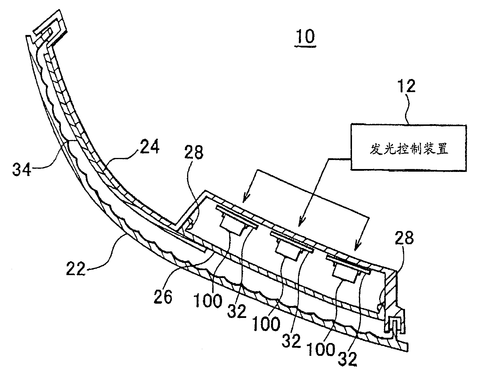
图1和图2示出根据本发明实施例的车灯10的结构的一个例子,具有发光控制装置12。图1是车灯10的水平截面图。图2为车灯10的正视图。根据此实施方案的车灯10是一个转向灯,并且稳定地发射棕色光。如图1和2所示的车灯10可安装于车辆的右前方。1 and 2 show an example of the structure of a
车灯10包括一个灯体24,一个外透镜22,多个衬底32,多个LED模块100,一个滤光片26和一个导光部件34。灯体24和外透镜22形成一个围绕车灯10的腔。多个衬底32和LED模块100位于此腔内以便实现防水。灯体24由树脂形成,以便从从车的后部覆盖多个衬底32和多个LED模块100。The
例如,外透镜由透明无色的材料制成,覆盖于车灯10的前表面。这样外透镜22就辐照从车前部的LED模块100发出的光。外透镜22可通过如热熔或焊接的方式连接于灯体24上。控制光分布的透镜台阶设置于面对外透镜22内多个LED模块100的表面上。外透镜22通过透镜台阶控制光辐射的方向。在另一个实施方案中,车灯10可以通过如LED模块100后面的反射镜控制光辐射的方向。For example, the outer lens is made of transparent and colorless material and covers the front surface of the
多个衬底32中的每一个固定于多个LED模块100中的每一个上。此外,多个衬底32中的每一个将LED模块100和发光控制单元12电连接。衬底32可被固定于灯体24之上。Each of the plurality of
多个LED模块100中的每一个通过衬底32接受发光控制单元12的能量发光。在本实施方案中,LED模块100接受能量后发白光。这样尽管车灯10温度升高,LED模块100也能发出光量和波长都稳定的光。LED模块100可通过接受发光控制单元12传送的间歇性的能量间歇性地发光。发光控制单元12是一个使多个LED模块100发光的发光电路。发光控制单元12通过如一个闪光灯继电器的装置为多个LED模块100供应能量,产生间歇性的能量。Each of the plurality of
滤光片26可为一个内透镜,一个彩色薄板或类似物,位于多个LED模块100和外透镜22之间。这样,滤光片26就将多个LED模块100发射的光传导至外透镜22。滤光片26用多个螺丝钉28固定于灯体24上。滤光片26也可用焊枪固定于灯体24上。在本实施例中,滤光片26由彩色透明的材料形成。这样,滤光片26就将LED模块100产生的白光变为预定颜色的光,传至外透镜22上。The
例如,滤光片26可以是传导波长不低于550nm的光波的滤片.在本实施方案中,滤光片26产生的在车灯中使用的预定的颜色的光为棕色光.这样,车灯10在LED模块100发射的白光的基础上产生棕色光.此外,棕色为必须在车灯的转向灯中使用的光的颜色.For example, the
导光部件34由滤光片26前部的一部分至车辆的侧表面构成,覆盖了灯体24至少前面的一部分。这样,导光部件34就将透过滤光片26的棕色光传导至车的侧表面。最终车灯10在几乎整个外透镜22的表面产生棕色光。根据本实施方案,车灯10能够稳定并适量地发射棕色光。The
图3示出了LED模块100结构的一个实施例。LED模块100包括多个电极104,一个衬底112,腔109,一个支撑部件118,一个密封部件108,一个发光二极管102以及一个磷光体106。FIG. 3 shows an embodiment of the structure of the
多个电极104与衬底32电连接,通过衬底32接收发光控制单元12的能量并通过衬底112将能量传至发光二极管102(见图1)。A plurality of electrodes 104 are electrically connected to the
衬底112具有平板形状,并且将发光二极管102固定于其上。此外,衬底112包括一条配线,将电极104和发光二极管102电连接,通过电极104将自发光控制单元12接收的能量传至发光二极管102。腔109是在衬底112上形成的环绕发光二极管102的壁表面。磷光体106固定于壁表面形成的内腔中。这样,磷光体106就覆盖于发光二极管102之上。The
支撑部件118支撑着多个电极104,衬底112,腔109以及密封部件108。此外,至少部分的支撑部件118是由导热性比空气高的材料形成,如金属,能够将发光二极管102产生的热量从LED模块100中排出。密封部件108是一个密封发光二极管102的模子。例如,密封部件108可由透明树脂制成。The supporting member 118 supports the plurality of electrodes 104 , the
发光二极管102是一个LED器件,例如,可使用InGaN,利用自发光控制单元12获得的能量发射蓝光。发光二极管102面对密封部件108的几乎整个表面为光发射区域,光则从此发射区域发射出去。The
磷光体106被设置为覆盖发光二极管102的表面,基于发光二极管102发射的蓝光发射波长长于蓝光的光。在另一个实施例中,磷光体106可置于密封部件108内。在当前的实施方案中,磷光体106发射与蓝光互补的黄光。这样,LED模块100就基于发光二极管102和磷光体106发射的蓝光和棕光产生白光。根据本实施方案,LED模块100可适当地产生白光。The
优选方案是LED模块100产生近似电灯泡颜色的白光。LED模块100可产生相当于色温为2500~3500K的黑体辐射分布的白光。Preferably, the
图4为发光二极管102,磷光体106同衬底112,腔109以及电极212a和212b的详细结构的实施例。例如,电极212a和212b可为焊条块,将发光二极管102和衬底112电连接在一起。FIG. 4 is an example of a detailed structure of
在当前的实施方案中,发光二极管102包括一个蓝宝石衬底210和半导体层208。发光二极管102通过倒装式接合固定于衬底112之上,这样蓝宝石衬底210就面对衬底112,将半导体层208夹在中间。此外,半导体层208包括N型GaN层202,InGaN层204,P型GaN层206。有以GaN为基础的半导体层AlxInyGa1-x-yN(0≤x<1,0≤y≤1,x+y≤1).此外,由于以GaN为基础的半导体层是不掺杂的无掺杂物层,以GaN为基础的半导体层可以用作N型层.然而,受体和供体的每种掺杂物都掺入GaN为基础的半导体层,这样就形成了针对每一个传导类型的以GaN为基础的半导体层.N型杂质包括Si,Ge和Sn,优选Si.P型杂质尤其不限制于此,包括Be,Zn,Mn,Cr,Mg,Ca等,优选Mg.N型GaN层202,InGaN层204和P型GaN层206按顺序层叠在蓝宝石衬底210朝向衬底112的一面.其它层可设置于这些层之间.In the current embodiment,
在这种情况下,N型GaN层202通过电极212b和衬底112连接。N型GaN层202还可形成于蓝宝石衬底210之上,AlxInyGa1-x-yN(0≤x<1,0≤y≤1,x+y≤1)缓冲层被夹在中间。In this case, the N-
InGaN层204作为发光层使用。InGaN层204可通过掺入N型或P型掺杂物形成,优选可通过掺入Si形成。此外,InGaN层204形成于N型GaN层202之上,中间加入例如N型AlGaN层。P型GaN层206形成于InGaN层204之上,把例如P型AlGaN层夹在中间,通过电极212a与衬底112连接。The
这样,以通过电极212a和212b以及衬底112获得的能量为基础,半导体层208可产生波长在440nm~460nm之间的蓝光。半导体层208将发出的光发射到蓝宝石衬底210,以透射蓝宝石衬底210。In this way, based on the energy obtained through the
磷光体106被设置于面对衬底112,将发光二极管102夹在中间以覆盖发光二极管102。磷光体106薄到可以透射至少部分发光二极管102发射的光,并且可以制成薄片形状。
在当前的实施方案中,磷光体106包括荧光材料302。磷光体106可以通过将荧光材料302的粉末掺入树脂等制成薄片形状。荧光材料302是被铈活化的以钇铝石榴石为基础荧光材料。此外,当前的实施方案中,优选荧光材料302中的至少部分铝可由镓替代,至少部分钇可被钆替代。这样,荧光材料302能产生比无替代物时波长更长或更短的的光。荧光材料302包括Y3Al5O12:Ce和/或Tb3Al5O12:Ce。荧光材料302可以是(RE1-xSmx)3(Al1-y-zInyGaz)5O12:Ce,其中0≤x<1,0≤y≤1,0≤z≤1,y+z≤1,RE至少为钇,钆和镧中的一种元素。In the current embodiment,
这样,本实施方案中的磷光体106在发光二极管102发射的蓝光的基础上产生580nm~600nm波长的光。磷光体106在蓝光基础上可产生波峰与棕色光波长相等或更长波长的光。磷光体106是长波磷光体的实施例。Thus, the
在另一个实施例中,磷光体106可通过将被铈激活的以钇铝石榴石为基础的荧光材料和产生红光的荧光材料混合而形成。产生红光的荧光材料包括如MxSiyNz:Eu(其中z=2x/3+4y/3,M至少为从由碱土金属组成的群体中选择的一种元素)。这种情况下,磷光体106产生波峰与棕色光波长相同或波长更长的光。In another embodiment, the
在本实施方案中,LED模块100通过混合发光二极管102发射的光和磷光体106发射的光而产生白光。根据本实施方案,可适当地产生白光。In this embodiment,
图5示出了LED模块100发射的白光光谱的一个实施例。在本实施方案中,LED模块100在发光二极管102发射的光和磷光体106发射的光基础上产生的光谱光在402和404处具有两个峰值。这种情况下,峰值402是由发光二极管102发射的蓝光产生,404由磷光体106发射的光产生。FIG. 5 shows an example of the spectrum of white light emitted by the
图6为滤光片26透射率的一个实施例。在本实施方案中,滤光片26阻断了几乎所有波长小于500nm的光。此外,滤光片26可透射几乎所有,即90%或更多波长不低于600nm的光。FIG. 6 is an embodiment of the transmittance of the
这种情况下,滤光片26阻断了所有在402处具有峰值的波长的光(见图5)。这样,滤光片26就阻断了几乎所有由发光二极管102发射的蓝光。此外,滤光片26透射几乎所有在404处具有峰值的波长的光(见图5)。这样,滤光片26透射磷光体106发射的光中几乎所有波长接近峰值404的光。In this case, the
更具体地讲,滤光片26阻断了几乎所有波长小于位置403处的光——此处在发光二极管和长波磷光体发射的连续光谱中光强最低。这时403位于由发光二极管102发射的光波峰402和长波磷光体106发射的光波峰404之间,如图5和10A的白光光谱所示。More specifically, filter 26 blocks nearly all light at wavelengths shorter than that at location 403 - where the light intensity is lowest in the continuum emitted by LEDs and long wave phosphors. At this
此外,如图10A所示,滤光片26的优选透射极限F1(见图10A,10B,10C),位于发光二极管102发射的光波峰402和长波磷光体106发射的光波峰404之间,并比在发光二极管和长波磷光体连续光谱S1中光强最低的403更接近长波的一端,且比长波磷光体发射的光波峰404更接近短波的一端。滤光片26阻断几乎所有,例如,90%或更多波长短于透射极限F1的光,透射至少部分波长大于透射极限F1的光。透射极限F1是当滤光片26(见图6)的透射率在约45°倾角时的波长。In addition, as shown in FIG. 10A, the preferred transmission limit F1 (see FIGS. 10A, 10B, and 10C) of the
通过提供连续光谱S1和透射极限F1,磷光体发射的光谱就确保了足够的半带宽。因此,就可获得具良好能见度的车灯。By providing a continuous spectrum S1 and a transmission limit F1, the spectrum emitted by the phosphor ensures a sufficient half-bandwidth. Therefore, a vehicle lamp with good visibility can be obtained.
此外,滤光片的透射极限F1可位于比长波磷光体发射的光波峰的50%更接近短波的一端。因此,就可获得具良好能见度的车灯。Furthermore, the transmission limit F1 of the filter may lie closer to the short-wave end than 50% of the peak of light emitted by the long-wave phosphor. Therefore, a vehicle lamp with good visibility can be obtained.
如前所述,透射极限F1比在发光二极管和长波磷光体连续光谱S1中光强最低的403更接近长波的一端,位于光强最低的403和长波磷光体106发射的光波峰404之间,且比长波磷光体发射的光波峰404的50%更接近短波的一端。因此,与常用的使用AlInGaP或GaAsP半导体的发光二极管相比,根据本发明的发光二极管具有更好的效果,这将在后面详述。As mentioned above, the transmission limit F1 is closer to one end of the long wave than the
图10A至10C为本发明车灯的每种发射光谱的图解,其中有使用基于AlInGaP的半导体发射棕色光的灯,以及本发明另一个实施例的灯。图10A为一个发光光谱,其中本实施方案中白光光谱S1靠近透射极限F1的短波端被滤光片阻断,其余的光从车灯发送到外面(通过实线表示,图10C同)。10A to 10C are illustrations of each emission spectrum of a vehicle lamp of the present invention, a lamp emitting brown light using an AlInGaP-based semiconductor, and a lamp of another embodiment of the present invention. Fig. 10A is a luminescence spectrum, wherein in this embodiment, the short-wave end of the white light spectrum S1 close to the transmission limit F1 is blocked by a filter, and the rest of the light is sent from the lamp to the outside (indicated by a solid line, the same as Fig. 10C).
通过本实施方案的车灯,本实施方案的棕色光光谱的半波长A大于如图10B所示使用AlInGaP型半导体发射棕色光的发光二极管发射光的发光光谱S2的半波长B。这是因为本发明的光谱具有棕色光波峰404,从由发光二极管发射的蓝光波峰402延续至此,并且磷光体光谱峰的较低部分延伸向短波的一端。这样,既然光谱的半波长更大,当作为转向灯时不仅能见度好,且对于生理健康的人,甚而色盲患者来说都具有足够的能见度。使用AlInGaP或类似物的发射棕色光的发光二极管以具有小的半波长为特征。最近,尽管使用灯丝的电灯已被发光二极管取代,仍然存在一个问题:色盲患者很难看见灯光。然而,本实施方案中的车灯可以利用发光二极管提高棕色光光谱的半波长。因此,本实施方案的车灯对色盲患者来说具有很好的能见度。With the vehicle lamp of this embodiment, the half-wavelength A of the brown light spectrum of this embodiment is greater than the half-wavelength B of the emission spectrum S2 of the light-emitting diode emitting light using an AlInGaP type semiconductor to emit brown light as shown in FIG. 10B . This is because the spectrum of the present invention has a brown
此外,用电灯和滤光片获得棕色光时,滤光片阻断了与本实施方案类似的短波波长的光.然而,由于电灯具有在整个可见光区域均匀分布的光谱,发光二极管作为发射棕色光的车灯时用lm/W(流明/瓦特)单位作比较,比电灯具有更高效率.在这里,lm/W是一个效率单位,表明消耗1W能量可发射多少光.尽管电灯在可见光的短波区域发射强光,滤光片能阻断所有的短波光.因此,能量供应的光输出效率不是很好.Also, when brown light is obtained with an electric lamp and a filter, the filter blocks light of short wavelengths similar to this embodiment. However, since electric lamps have a spectrum that is evenly distributed throughout the visible region, LEDs emit brown light as Compared with the unit of lm/W (lumen/watt) in the car lights, it has higher efficiency than electric lamps. Here, lm/W is an efficiency unit, indicating how much light can be emitted by consuming 1W of energy. Although the electric lamp is in the short wave of visible light The area emits strong light, and the filter blocks all short-wavelength light. Therefore, the light output efficiency of the energy supply is not very good.
图10C示出了本发明的另一个实施方案。图10C的实施方案与图10A的不同之处在于,车灯的发光二极管发射的部分棕色光被阻断了。本实施例的车灯包括一个发光二极管,一个长波磷光体和类似图10A所示实施方案的滤光片。这里,所述灯滤光片的透射极限F1比发光二极管和长波磷光体发射的连续光谱S3中光强最低的405更接近短波的一端。这种灯解决了一个问题:使用AlInGaP发光二极管的传统车灯的棕色光波峰随气温变化而变化,如图10B所示。因此,得到一种能见度高的车灯是可以实现的,因为波长不会随温度而变化。Figure 10C shows another embodiment of the present invention. The embodiment of FIG. 10C differs from FIG. 10A in that part of the brown light emitted by the light emitting diodes of the car lights is blocked. The vehicle light of this embodiment includes an LED, a long wave phosphor and a filter similar to the embodiment shown in FIG. 10A. Here, the transmission limit F1 of the lamp filter is closer to the short-wave end than the light-
在图10C示出的本发明的另一个实施方案中,可能从发光二极管在透射极限F1检测到光,立即得知在工作过程中发光二极管的衰变。本发明的车灯利用发光二极管发出的光激发磷光体发光,并使用激发光。这样就很难检测由于发光二极管的温度变化产生的光波长改变。自一开始使用,光波长变化越大,发光二极管衰变的越快。因此,发光二极管的使用寿命因使用条件的不同而不同,在使用灯时通过检测光波长的变化可预测其寿命。根据一种检测方法,在透射极限测定光强时使用光敏元件来检测透射极限的光(接近透射极限的光),当发光二极管的波峰向长波方向变化时光强变大,当发光二极管的波峰向短波方向变化时光强变小。通过检测光强的变化来预测发光二极管的使用寿命。In another embodiment of the invention shown in FIG. 1OC, it is possible to immediately know the decay of the LED during operation from the detection of light by the LED at the transmission limit F1. The vehicle lamp of the present invention utilizes the light emitted by the light-emitting diode to excite the phosphor to emit light, and uses the excitation light. This makes it difficult to detect changes in the wavelength of light due to temperature changes in the light emitting diodes. The more the wavelength of light changes, the faster the LED will decay since it was first used. Therefore, the service life of light-emitting diodes varies depending on the conditions of use, and its service life can be predicted by detecting changes in the wavelength of light when the lamp is in use. According to a detection method, a photosensitive element is used to detect light at the transmission limit (light close to the transmission limit) when measuring the light intensity at the transmission limit. When the wave peak of the LED changes to the long-wave direction, the light intensity becomes larger. The light intensity becomes smaller as the direction of the short wave changes. Predict the service life of light-emitting diodes by detecting changes in light intensity.
尽管本实施方案针对由发光二极管和磷光体发射的具两个峰值的连续光谱S1和滤光片的透射极限的组合做出了描述,通过多种长波磷光体材料的组合,该连续光谱S1也可具两个或更多个波峰。这种情况下,在发光二极管和长波磷光体发射的连续光谱中光强最低的位置就是接近透射极限的位置,也是光谱的转折点。滤光片的透射极限位于转折点的长波端,长波磷光体波峰的短波端。Although the present embodiment has been described for the combination of the continuous spectrum S1 with two peaks emitted by the light-emitting diode and the phosphor and the transmission limit of the filter, the continuous spectrum S1 can also be obtained by combining various long-wave phosphor materials. Can have two or more peaks. In this case, the lowest light intensity position in the continuous spectrum emitted by LEDs and long-wave phosphors is close to the transmission limit, which is also the turning point of the spectrum. The transmission limit of the filter is at the long-wave end of the turning point and the short-wave end of the long-wave phosphor peak.
图7示出了滤光片26透射的光的色度的实施例。区域408(图中阴影线的区域)表明转向灯中使用的棕色色度范围。转向灯中使用棕色在美国,日本和欧洲正在标准化。例如,在日本,在JIS D5500中化的棕色为如下的橙色。FIG. 7 shows an example of the chromaticity of light transmitted by the
0.429≥y≥0.398,z≤0.0070.429≥y≥0.398, z≤0.007
在欧洲的ECE条例中标准化的棕色如下。The brown color standardized in the European ECE regulation is as follows.
y≥0.39,y≥0.79-0.67x,y≤x-0.12y≥0.39, y≥0.79-0.67x, y≤x-0.12
在美国,在SAE J578c和J578d中棕色的标准如下。In the United States, the standards for brown in SAE J578c and J578d are as follows.
y=0.39,y=0.79-0.67x,y=x-0.12y=0.39, y=0.79-0.67x, y=x-0.12
其中,z=1-x-y,xyz是色度的坐标。Wherein, z=1-x-y, xyz is the coordinate of chromaticity.
在当前的实施方案中,滤光片26透射图5描述的光的光谱,透射率如图6所示。在这种情况下,滤光片26产生点406所示的色度的光。因此根据本发明,滤光片26以发光二极管102和磷光体106发射的光为基础产生棕色光。滤光片26可产生色度范围内由区域408描述的用于转向灯中的棕色光。In the current embodiment, the
这里,当使用诸如AlInGaP,GaAsP或类似物的发光二极管产生棕色光时,光量的减少或光波长的变化可能因某些情况下车灯10温度的升高而发生。然而,在当前的发明中,LED模块100产生白光。这种情况下,尽管车灯10温度升高,LED模块100能产生光量和波长稳定的光。因此,根据本发明,无论车灯10的温度是否变化,车灯10都可稳定发射棕色光,。Here, when brown light is generated using a light emitting diode such as AlInGaP, GaAsP, or the like, a decrease in light quantity or a change in light wavelength may occur due to an increase in temperature of the
根据本实施方案,车灯阻断了发光二极管发射的几乎全部的光,并且以被发光二极管的光激发的磷光体产生的光获得使用于转向灯中的棕色。因此,所述车灯解决了这样的问题——发光二极管的波峰由于使用AlInGaP或类似物的二极管产生温度变化而改变,故而车灯具有很好的能见度,因为本实施方案中波长不会随温度而变化。According to the present embodiment, the vehicle lamp blocks almost all light emitted by the light-emitting diode, and obtains the brown color used in the turn signal with the light generated by the phosphor excited by the light of the light-emitting diode. Therefore, the car lamp solves the problem that the peak of the light-emitting diode changes due to the temperature change of the diode using AlInGaP or the like, so the car lamp has good visibility because the wavelength does not vary with temperature in this embodiment. And change.
此外,当使用AlInGaP,GaAs或类似物的P发光二极管时,通过增加发光二极管的数量来抵消光量的减少,可能增加车灯10的成本。但是本实施方案中,滤光片26由树脂构成,成本较低。因此根据本实施方案,能得到成本较低的车灯10。In addition, when P light-emitting diodes of AlInGaP, GaAs, or the like are used, the cost of the
图8示出了滤光片26透射的光的光谱的实施例。在本实施方案中,滤光片26产生的光在590nm附近具有峰值。优选滤光片26产生的光在587~596nm处具有峰值。FIG. 8 shows an example of the spectrum of light transmitted by the
图9示出了另一个车灯10的结构的实施例。图9中省略了对与图1中相同的各个附图标记的解释,因为它们的功能和在图1中相同。FIG. 9 shows another example of the structure of a
在当前的实施方案中,外透镜22具有和滤光片26相同或相似的功能(见图1)。这样,外透镜22在发光二极管102和磷光体106发射的光的基础上产生了棕色光。外透镜22由彩色透明材料构成,故而具有透光度,如图6所示。本实施方案中,车灯10也可稳定发射棕色光。In the present embodiment, the
在另一个实施例中,具有TiO2或类似物的光催化作用的光催化膜可设置在车灯内发光二极管发射的光到达的位置。尽管光催化膜可设置在车灯内的任何位置,为防止投射光的吸收,光催化膜优选设置在远离光投射部件的位置。此外,优选将光催化膜设置在光学部件的连接部件上或连接部件附近。这样,就可能使用催化作用解决外部水汽通过连接部件渗透或连接部件产生的少量气体的问题,使工作寿命延长,并且改善可靠性。因此,被阻断的可见光和波长比可见光更短的光可作为激发磷光体的光源,并有效地用于光催化剂中。In another embodiment, a photocatalytic film with a photocatalytic effect of TiO2 or the like can be placed in a car lamp where light emitted from an LED reaches. Although the photocatalytic film may be provided at any position within the vehicle lamp, in order to prevent absorption of projected light, the photocatalytic film is preferably provided at a position away from the light projecting member. In addition, it is preferable to provide the photocatalyst film on or in the vicinity of the connecting member of the optical member. Thus, it is possible to use catalysis to solve the problem of external water vapor permeating through the connection part or a small amount of gas generated from the connection part, resulting in a longer operating life and improved reliability. Therefore, blocked visible light and light with a shorter wavelength than visible light can be used as a light source for exciting phosphors and effectively used in photocatalysts.
尽管本发明已通过典型实施方案做出描述,应当理解的是,本领域技术人员可据此做出很多变化和替换而不背离本发明的要旨和范围。从附属权利要求的限定可明显看出,具有这些改进的实施方案也属于本发明的范围。Although the present invention has been described with typical embodiments, it should be understood that those skilled in the art can make many changes and substitutions without departing from the spirit and scope of the present invention. Embodiments with these modifications also fall within the scope of the invention as is evident from the definition of the appended claims.
Claims (7)
Applications Claiming Priority (6)
| Application Number | Priority Date | Filing Date | Title |
|---|---|---|---|
| JP2003333116 | 2003-09-25 | ||
| JP333116/03 | 2003-09-25 | ||
| JP333116/2003 | 2003-09-25 | ||
| JP237912/04 | 2004-08-18 | ||
| JP237912/2004 | 2004-08-18 | ||
| JP2004237912A JP4378242B2 (en) | 2003-09-25 | 2004-08-18 | Vehicle lighting |
Publications (2)
| Publication Number | Publication Date |
|---|---|
| CN1664440A CN1664440A (en) | 2005-09-07 |
| CN1664440B true CN1664440B (en) | 2010-05-12 |
Family
ID=33422231
Family Applications (1)
| Application Number | Title | Priority Date | Filing Date |
|---|---|---|---|
| CN2004100997859A Expired - Lifetime CN1664440B (en) | 2003-09-25 | 2004-09-27 | headlights |
Country Status (6)
| Country | Link |
|---|---|
| US (1) | US7168834B2 (en) |
| JP (1) | JP4378242B2 (en) |
| KR (1) | KR100661380B1 (en) |
| CN (1) | CN1664440B (en) |
| DE (1) | DE102004046850B4 (en) |
| GB (1) | GB2406900B (en) |
Cited By (1)
| Publication number | Priority date | Publication date | Assignee | Title |
|---|---|---|---|---|
| TWI421449B (en) * | 2011-02-01 | 2014-01-01 | Lite On Electronics Guangzhou | Lighting device and method for selecting color of toner in medium layer thereof |
Families Citing this family (47)
| Publication number | Priority date | Publication date | Assignee | Title |
|---|---|---|---|---|
| JP4784966B2 (en) * | 2003-11-18 | 2011-10-05 | シャープ株式会社 | Semiconductor laser device and illumination device |
| CN101076744B (en) * | 2004-04-23 | 2010-05-12 | 光处方革新有限公司 | Optical manifold for light emitting diodes |
| US7648649B2 (en) * | 2005-02-02 | 2010-01-19 | Lumination Llc | Red line emitting phosphors for use in led applications |
| US20070114562A1 (en) * | 2005-11-22 | 2007-05-24 | Gelcore, Llc | Red and yellow phosphor-converted LEDs for signal applications |
| US7358542B2 (en) | 2005-02-02 | 2008-04-15 | Lumination Llc | Red emitting phosphor materials for use in LED and LCD applications |
| US7497973B2 (en) * | 2005-02-02 | 2009-03-03 | Lumination Llc | Red line emitting phosphor materials for use in LED applications |
| CN101283457B (en) * | 2005-10-05 | 2010-06-09 | 皇家飞利浦电子股份有限公司 | Phosphor-converted electroluminescent device with absorption filter |
| US8159126B2 (en) * | 2005-11-07 | 2012-04-17 | Koninklijke Philips Electronics N.V. | Light emitting device with an improved CaAlSiN light converting material |
| EP1958257A2 (en) * | 2005-11-24 | 2008-08-20 | Koninklijke Philips Electronics N.V. | Light emitting diode construction |
| JP5319294B2 (en) * | 2005-12-12 | 2013-10-16 | コーニンクレッカ フィリップス エヌ ヴェ | LED collimator element for automobile headlight with low beam function |
| JP5006549B2 (en) * | 2006-02-07 | 2012-08-22 | 株式会社小糸製作所 | Vehicle sign light |
| JP4992250B2 (en) * | 2006-03-01 | 2012-08-08 | 日亜化学工業株式会社 | Light emitting device |
| US7937865B2 (en) * | 2006-03-08 | 2011-05-10 | Intematix Corporation | Light emitting sign and display surface therefor |
| US8998433B2 (en) | 2006-03-08 | 2015-04-07 | Intematix Corporation | Light emitting device utilizing remote wavelength conversion with improved color characteristics |
| DE102006043280A1 (en) * | 2006-09-14 | 2008-03-27 | Hella Kgaa Hueck & Co. | Vehicle turn signal light, has photoresist aperture arranged between lens and reflector and between lens and closure lens, where opening has smaller diameter than outer diameter of reflector |
| US20090010013A1 (en) * | 2007-07-02 | 2009-01-08 | Andre Hessling | Light for a vehicle, particularly flash warning light for an aircraft |
| US7847309B2 (en) * | 2007-07-16 | 2010-12-07 | GE Lighting Solutions, LLC | Red line emitting complex fluoride phosphors activated with Mn4+ |
| JP5941243B2 (en) | 2007-10-17 | 2016-06-29 | スタンレー電気株式会社 | Light emitting device, vehicle lamp using the same, and headlamp |
| TWI370216B (en) * | 2009-06-29 | 2012-08-11 | Lextar Electronics Corp | Led lighting device |
| JP2011014766A (en) * | 2009-07-03 | 2011-01-20 | Koito Mfg Co Ltd | Light emitting module and automotive lamp |
| JP2011108588A (en) * | 2009-11-20 | 2011-06-02 | Koito Mfg Co Ltd | Light emitting module and vehicle lamp |
| KR200460629Y1 (en) * | 2010-02-17 | 2012-06-13 | 정승문 | Color lighting device |
| JP5514677B2 (en) * | 2010-09-07 | 2014-06-04 | 株式会社オペス | LED lighting device |
| JP5658970B2 (en) * | 2010-10-20 | 2015-01-28 | 株式会社ミツバ | door mirror |
| JP5731798B2 (en) * | 2010-11-09 | 2015-06-10 | 日本フネン株式会社 | LED lamps used for pedestrian traffic lights |
| JP5957464B2 (en) * | 2010-12-17 | 2016-07-27 | コーニンクレッカ フィリップス エヌ ヴェKoninklijke Philips N.V. | Illumination system comprising a light source, a radiation conversion element, and a filter |
| US8461752B2 (en) * | 2011-03-18 | 2013-06-11 | Abl Ip Holding Llc | White light lamp using semiconductor light emitter(s) and remotely deployed phosphor(s) |
| US8803412B2 (en) * | 2011-03-18 | 2014-08-12 | Abl Ip Holding Llc | Semiconductor lamp |
| US8398282B2 (en) * | 2011-05-12 | 2013-03-19 | Delphi Technologies, Inc. | Vehicle front lighting assembly and systems having a variable tint electrowetting element |
| JP5378558B2 (en) * | 2012-02-20 | 2013-12-25 | 株式会社小糸製作所 | Vehicle sign light |
| US20140022808A1 (en) * | 2012-07-19 | 2014-01-23 | Kwun Wah Chan | LED Light Module for Vehicle |
| JP6094700B2 (en) * | 2013-03-04 | 2017-03-15 | 信越化学工業株式会社 | Vehicle direction indicator |
| JP2014197527A (en) | 2013-03-04 | 2014-10-16 | 信越化学工業株式会社 | Vehicle direction indicator |
| CN103363416A (en) * | 2013-07-24 | 2013-10-23 | 苏州市润凯汽车配件制造有限公司 | Emergency lamp for vehicle |
| JP6419729B2 (en) | 2014-01-24 | 2018-11-07 | 株式会社小糸製作所 | Vehicle lighting |
| DE102014211833A1 (en) * | 2014-06-20 | 2015-12-24 | Osram Gmbh | Signaling by means of semiconductor light sources |
| KR101620193B1 (en) * | 2014-09-26 | 2016-05-12 | 현대자동차주식회사 | Laser optical system for head lamp |
| US9791124B2 (en) | 2016-02-23 | 2017-10-17 | MLS Automotive, Inc. | Vehicle lighting assembly and method for achieving yellow colored turn signals |
| KR200481980Y1 (en) * | 2016-08-19 | 2016-12-02 | 에스엘 주식회사 | Lamp for vehicle |
| JP6883418B2 (en) * | 2016-12-19 | 2021-06-09 | 株式会社小糸製作所 | Vehicle lamp |
| US11177423B2 (en) | 2017-05-19 | 2021-11-16 | Citizen Electronics Co., Ltd. | Light emitting device |
| JP2019114480A (en) * | 2017-12-25 | 2019-07-11 | トヨタ自動車株式会社 | Vehicular lighting fixture |
| JP6769449B2 (en) | 2018-01-30 | 2020-10-14 | 日亜化学工業株式会社 | Lighting equipment |
| KR102550462B1 (en) * | 2018-03-09 | 2023-07-03 | 쑤저우 레킨 세미컨덕터 컴퍼니 리미티드 | Light emitting device package |
| JP7332881B2 (en) * | 2019-09-30 | 2023-08-24 | 日亜化学工業株式会社 | light emitting device |
| JP7527155B2 (en) * | 2020-08-21 | 2024-08-02 | 株式会社ファルテック | Screen grill |
| US20240234648A1 (en) | 2021-04-19 | 2024-07-11 | Nichia Corporation | Light emitting device, headlight, and vehicle comprising same |
Citations (1)
| Publication number | Priority date | Publication date | Assignee | Title |
|---|---|---|---|---|
| CN1207206A (en) * | 1996-09-20 | 1999-02-03 | 西门子公司 | Wavelength converting casting material, its use and method of manufacture |
Family Cites Families (26)
| Publication number | Priority date | Publication date | Assignee | Title |
|---|---|---|---|---|
| DE3420175A1 (en) * | 1984-05-30 | 1985-12-05 | SWF Auto-Electric GmbH, 7120 Bietigheim-Bissingen | Signal lamp emitting coloured light, in particular for vehicles |
| JP2815692B2 (en) * | 1990-09-28 | 1998-10-27 | 株式会社小糸製作所 | Automotive projection headlamps |
| JPH0589703A (en) * | 1991-09-30 | 1993-04-09 | Koito Mfg Co Ltd | Vehicle lighting fixture |
| JPH0623195U (en) | 1992-07-29 | 1994-03-25 | シンロイヒ株式会社 | EL light emitting element |
| FR2707223B1 (en) * | 1993-07-07 | 1995-09-29 | Valeo Vision | Improved signaling light with light-emitting diodes. |
| KR100200199B1 (en) * | 1994-08-02 | 1999-06-15 | 사또 아끼오 | Polyimide resin compositions for optical filters |
| JP3544010B2 (en) * | 1994-10-25 | 2004-07-21 | 本田技研工業株式会社 | Vehicle lighting |
| TW383508B (en) * | 1996-07-29 | 2000-03-01 | Nichia Kagaku Kogyo Kk | Light emitting device and display |
| JP3772801B2 (en) | 1996-11-05 | 2006-05-10 | 日亜化学工業株式会社 | Light emitting diode |
| EP0965034B1 (en) * | 1997-03-07 | 2007-05-30 | Clare Chemical Research, Inc. | Fluorometric detection using visible light |
| US5813752A (en) | 1997-05-27 | 1998-09-29 | Philips Electronics North America Corporation | UV/blue LED-phosphor device with short wave pass, long wave pass band pass and peroit filters |
| US5813753A (en) | 1997-05-27 | 1998-09-29 | Philips Electronics North America Corporation | UV/blue led-phosphor device with efficient conversion of UV/blues light to visible light |
| DE29818264U1 (en) * | 1998-10-13 | 1998-12-17 | Mihmat, Tarkan, 81475 München | Lighting system for a motor vehicle and incandescent lamp for a direction indicator of such a lighting system |
| US6595669B2 (en) * | 1998-11-02 | 2003-07-22 | Code 3, Inc. | Vehicular warning light having less apparent color when not energized |
| JP3352989B2 (en) * | 1999-07-16 | 2002-12-03 | スタンレー電気株式会社 | Signal lights for vehicles |
| JP3809760B2 (en) * | 2000-02-18 | 2006-08-16 | 日亜化学工業株式会社 | Light emitting diode |
| JP2002050800A (en) * | 2000-05-24 | 2002-02-15 | Nichia Chem Ind Ltd | Light emitting device and method for forming the same |
| US6520669B1 (en) | 2000-06-19 | 2003-02-18 | Light Sciences Corporation | Flexible substrate mounted solid-state light sources for exterior vehicular lighting |
| GB0015561D0 (en) * | 2000-06-27 | 2000-08-16 | Oxley Dev Co Ltd | Filter |
| DE10036940A1 (en) * | 2000-07-28 | 2002-02-07 | Patent Treuhand Ges Fuer Elektrische Gluehlampen Mbh | Luminescence conversion LED |
| JP4592172B2 (en) * | 2000-10-26 | 2010-12-01 | スタンレー電気株式会社 | Vehicle lighting |
| JP2002231013A (en) | 2001-01-29 | 2002-08-16 | Koito Mfg Co Ltd | Light-emitting diode and lighting fixture for vehicle using same |
| JP2003059310A (en) * | 2001-08-09 | 2003-02-28 | Toyoda Gosei Co Ltd | Vehicle rear lamp |
| DE10142009B4 (en) * | 2001-08-28 | 2010-04-22 | Osram Opto Semiconductors Gmbh | LED light source with a conversion agent and with a UV absorbing layer |
| EP2262008B1 (en) * | 2002-01-28 | 2015-12-16 | Nichia Corporation | Nitride semiconductor element with supporting substrate and method for producing nitride semiconductor element |
| TWI292961B (en) * | 2002-09-05 | 2008-01-21 | Nichia Corp | Semiconductor device and an optical device using the semiconductor device |
-
2004
- 2004-08-18 JP JP2004237912A patent/JP4378242B2/en not_active Expired - Fee Related
- 2004-09-24 US US10/949,881 patent/US7168834B2/en not_active Expired - Lifetime
- 2004-09-25 KR KR1020040077669A patent/KR100661380B1/en not_active Expired - Lifetime
- 2004-09-27 GB GB0421464A patent/GB2406900B/en not_active Expired - Lifetime
- 2004-09-27 DE DE102004046850A patent/DE102004046850B4/en not_active Expired - Lifetime
- 2004-09-27 CN CN2004100997859A patent/CN1664440B/en not_active Expired - Lifetime
Patent Citations (1)
| Publication number | Priority date | Publication date | Assignee | Title |
|---|---|---|---|---|
| CN1207206A (en) * | 1996-09-20 | 1999-02-03 | 西门子公司 | Wavelength converting casting material, its use and method of manufacture |
Cited By (1)
| Publication number | Priority date | Publication date | Assignee | Title |
|---|---|---|---|---|
| TWI421449B (en) * | 2011-02-01 | 2014-01-01 | Lite On Electronics Guangzhou | Lighting device and method for selecting color of toner in medium layer thereof |
Also Published As
| Publication number | Publication date |
|---|---|
| US7168834B2 (en) | 2007-01-30 |
| GB0421464D0 (en) | 2004-10-27 |
| KR100661380B1 (en) | 2006-12-27 |
| DE102004046850A1 (en) | 2005-06-23 |
| KR20050030876A (en) | 2005-03-31 |
| JP2005123165A (en) | 2005-05-12 |
| CN1664440A (en) | 2005-09-07 |
| GB2406900B (en) | 2007-09-12 |
| US20050117361A1 (en) | 2005-06-02 |
| DE102004046850B4 (en) | 2011-03-31 |
| JP4378242B2 (en) | 2009-12-02 |
| GB2406900A (en) | 2005-04-13 |
Similar Documents
| Publication | Publication Date | Title |
|---|---|---|
| CN1664440B (en) | headlights | |
| US7193358B2 (en) | Light-emitting device arranged in the light distribution pattern for a vehicle | |
| KR100705053B1 (en) | Light emitting diode device | |
| US6603258B1 (en) | Light emitting diode device that emits white light | |
| US8269245B1 (en) | Optical device with wavelength selective reflector | |
| JP5653503B2 (en) | White light emitting device, backlight, liquid crystal display device and lighting device | |
| CN104253205B (en) | Semiconductor light emitting device and its manufacturing method | |
| US20100301360A1 (en) | Lighting devices with discrete lumiphor-bearing regions on remote surfaces thereof | |
| JP4411892B2 (en) | Light source device and vehicle headlamp using the same | |
| JP2009289976A (en) | Light emitting device | |
| JP2011243369A (en) | Light-emitting device, illumination device, and vehicle headlight | |
| US8017961B2 (en) | Light emitting device and phosphor of alkaline earth sulfide therefor | |
| JP2013168586A (en) | Light emitting device, semiconductor laser element, vehicle headlamp and lighting device | |
| WO2013051623A1 (en) | Light-emitting body, illumination device, and headlight | |
| JP2012193283A (en) | Light-emitting body, illuminating device, and headlight | |
| JP4432414B2 (en) | Light source device and vehicle headlamp | |
| JP4806889B2 (en) | Light source device and illumination device | |
| JP2005159178A (en) | Light emitting device and light source device using the same | |
| JP4432413B2 (en) | Light source device and vehicle headlamp | |
| JP4880329B2 (en) | Vehicle lighting | |
| US20120008306A1 (en) | Light emitting module and lamp unit | |
| KR20170075966A (en) | Light emitting device package having enhanced light extracting efficiency | |
| KR101170992B1 (en) | LED lamp | |
| JP4525650B2 (en) | Light emitting device that emits white light | |
| JP5045193B2 (en) | Semiconductor laser device |
Legal Events
| Date | Code | Title | Description |
|---|---|---|---|
| C06 | Publication | ||
| PB01 | Publication | ||
| C10 | Entry into substantive examination | ||
| SE01 | Entry into force of request for substantive examination | ||
| C14 | Grant of patent or utility model | ||
| GR01 | Patent grant | ||
| CX01 | Expiry of patent term |
Granted publication date: 20100512 |
|
| CX01 | Expiry of patent term |