CN1619876B - Battery - Google Patents
Battery Download PDFInfo
- Publication number
- CN1619876B CN1619876B CN2004100824366A CN200410082436A CN1619876B CN 1619876 B CN1619876 B CN 1619876B CN 2004100824366 A CN2004100824366 A CN 2004100824366A CN 200410082436 A CN200410082436 A CN 200410082436A CN 1619876 B CN1619876 B CN 1619876B
- Authority
- CN
- China
- Prior art keywords
- battery
- battery pack
- cell
- battery cell
- voltage
- Prior art date
- Legal status (The legal status is an assumption and is not a legal conclusion. Google has not performed a legal analysis and makes no representation as to the accuracy of the status listed.)
- Expired - Lifetime
Links
Images


Classifications
-
- B—PERFORMING OPERATIONS; TRANSPORTING
- B23—MACHINE TOOLS; METAL-WORKING NOT OTHERWISE PROVIDED FOR
- B23D—PLANING; SLOTTING; SHEARING; BROACHING; SAWING; FILING; SCRAPING; LIKE OPERATIONS FOR WORKING METAL BY REMOVING MATERIAL, NOT OTHERWISE PROVIDED FOR
- B23D45/00—Sawing machines or sawing devices with circular saw blades or with friction saw discs
-
- B—PERFORMING OPERATIONS; TRANSPORTING
- B23—MACHINE TOOLS; METAL-WORKING NOT OTHERWISE PROVIDED FOR
- B23D—PLANING; SLOTTING; SHEARING; BROACHING; SAWING; FILING; SCRAPING; LIKE OPERATIONS FOR WORKING METAL BY REMOVING MATERIAL, NOT OTHERWISE PROVIDED FOR
- B23D47/00—Sawing machines or sawing devices working with circular saw blades, characterised only by constructional features of particular parts
-
- B—PERFORMING OPERATIONS; TRANSPORTING
- B25—HAND TOOLS; PORTABLE POWER-DRIVEN TOOLS; MANIPULATORS
- B25F—COMBINATION OR MULTI-PURPOSE TOOLS NOT OTHERWISE PROVIDED FOR; DETAILS OR COMPONENTS OF PORTABLE POWER-DRIVEN TOOLS NOT PARTICULARLY RELATED TO THE OPERATIONS PERFORMED AND NOT OTHERWISE PROVIDED FOR
- B25F5/00—Details or components of portable power-driven tools not particularly related to the operations performed and not otherwise provided for
-
- H—ELECTRICITY
- H01—ELECTRIC ELEMENTS
- H01M—PROCESSES OR MEANS, e.g. BATTERIES, FOR THE DIRECT CONVERSION OF CHEMICAL ENERGY INTO ELECTRICAL ENERGY
- H01M10/00—Secondary cells; Manufacture thereof
-
- H—ELECTRICITY
- H01—ELECTRIC ELEMENTS
- H01M—PROCESSES OR MEANS, e.g. BATTERIES, FOR THE DIRECT CONVERSION OF CHEMICAL ENERGY INTO ELECTRICAL ENERGY
- H01M10/00—Secondary cells; Manufacture thereof
- H01M10/42—Methods or arrangements for servicing or maintenance of secondary cells or secondary half-cells
- H01M10/44—Methods for charging or discharging
-
- H—ELECTRICITY
- H01—ELECTRIC ELEMENTS
- H01M—PROCESSES OR MEANS, e.g. BATTERIES, FOR THE DIRECT CONVERSION OF CHEMICAL ENERGY INTO ELECTRICAL ENERGY
- H01M10/00—Secondary cells; Manufacture thereof
- H01M10/42—Methods or arrangements for servicing or maintenance of secondary cells or secondary half-cells
- H01M10/48—Accumulators combined with arrangements for measuring, testing or indicating the condition of cells, e.g. the level or density of the electrolyte
-
- H—ELECTRICITY
- H01—ELECTRIC ELEMENTS
- H01M—PROCESSES OR MEANS, e.g. BATTERIES, FOR THE DIRECT CONVERSION OF CHEMICAL ENERGY INTO ELECTRICAL ENERGY
- H01M4/00—Electrodes
- H01M4/02—Electrodes composed of, or comprising, active material
- H01M4/36—Selection of substances as active materials, active masses, active liquids
- H01M4/58—Selection of substances as active materials, active masses, active liquids of inorganic compounds other than oxides or hydroxides, e.g. sulfides, selenides, tellurides, halogenides or LiCoFy; of polyanionic structures, e.g. phosphates, silicates or borates
-
- H—ELECTRICITY
- H01—ELECTRIC ELEMENTS
- H01M—PROCESSES OR MEANS, e.g. BATTERIES, FOR THE DIRECT CONVERSION OF CHEMICAL ENERGY INTO ELECTRICAL ENERGY
- H01M6/00—Primary cells; Manufacture thereof
- H01M6/50—Methods or arrangements for servicing or maintenance, e.g. for maintaining operating temperature
-
- H02J4/25—
-
- H—ELECTRICITY
- H02—GENERATION; CONVERSION OR DISTRIBUTION OF ELECTRIC POWER
- H02J—CIRCUIT ARRANGEMENTS OR SYSTEMS FOR SUPPLYING OR DISTRIBUTING ELECTRIC POWER; SYSTEMS FOR STORING ELECTRIC ENERGY
- H02J7/00—Circuit arrangements for charging or depolarising batteries or for supplying loads from batteries
- H02J7/02—Circuit arrangements for charging or depolarising batteries or for supplying loads from batteries for charging batteries from AC mains by converters
-
- H—ELECTRICITY
- H01—ELECTRIC ELEMENTS
- H01M—PROCESSES OR MEANS, e.g. BATTERIES, FOR THE DIRECT CONVERSION OF CHEMICAL ENERGY INTO ELECTRICAL ENERGY
- H01M10/00—Secondary cells; Manufacture thereof
- H01M10/05—Accumulators with non-aqueous electrolyte
- H01M10/052—Li-accumulators
-
- H—ELECTRICITY
- H01—ELECTRIC ELEMENTS
- H01M—PROCESSES OR MEANS, e.g. BATTERIES, FOR THE DIRECT CONVERSION OF CHEMICAL ENERGY INTO ELECTRICAL ENERGY
- H01M10/00—Secondary cells; Manufacture thereof
- H01M10/05—Accumulators with non-aqueous electrolyte
- H01M10/052—Li-accumulators
- H01M10/0525—Rocking-chair batteries, i.e. batteries with lithium insertion or intercalation in both electrodes; Lithium-ion batteries
-
- H—ELECTRICITY
- H01—ELECTRIC ELEMENTS
- H01M—PROCESSES OR MEANS, e.g. BATTERIES, FOR THE DIRECT CONVERSION OF CHEMICAL ENERGY INTO ELECTRICAL ENERGY
- H01M10/00—Secondary cells; Manufacture thereof
- H01M10/36—Accumulators not provided for in groups H01M10/05-H01M10/34
-
- H—ELECTRICITY
- H01—ELECTRIC ELEMENTS
- H01M—PROCESSES OR MEANS, e.g. BATTERIES, FOR THE DIRECT CONVERSION OF CHEMICAL ENERGY INTO ELECTRICAL ENERGY
- H01M50/00—Constructional details or processes of manufacture of the non-active parts of electrochemical cells other than fuel cells, e.g. hybrid cells
- H01M50/20—Mountings; Secondary casings or frames; Racks, modules or packs; Suspension devices; Shock absorbers; Transport or carrying devices; Holders
- H01M50/233—Mountings; Secondary casings or frames; Racks, modules or packs; Suspension devices; Shock absorbers; Transport or carrying devices; Holders characterised by physical properties of casings or racks, e.g. dimensions
- H01M50/242—Mountings; Secondary casings or frames; Racks, modules or packs; Suspension devices; Shock absorbers; Transport or carrying devices; Holders characterised by physical properties of casings or racks, e.g. dimensions adapted for protecting batteries against vibrations, collision impact or swelling
-
- H—ELECTRICITY
- H01—ELECTRIC ELEMENTS
- H01M—PROCESSES OR MEANS, e.g. BATTERIES, FOR THE DIRECT CONVERSION OF CHEMICAL ENERGY INTO ELECTRICAL ENERGY
- H01M50/00—Constructional details or processes of manufacture of the non-active parts of electrochemical cells other than fuel cells, e.g. hybrid cells
- H01M50/20—Mountings; Secondary casings or frames; Racks, modules or packs; Suspension devices; Shock absorbers; Transport or carrying devices; Holders
- H01M50/271—Lids or covers for the racks or secondary casings
-
- H—ELECTRICITY
- H01—ELECTRIC ELEMENTS
- H01M—PROCESSES OR MEANS, e.g. BATTERIES, FOR THE DIRECT CONVERSION OF CHEMICAL ENERGY INTO ELECTRICAL ENERGY
- H01M50/00—Constructional details or processes of manufacture of the non-active parts of electrochemical cells other than fuel cells, e.g. hybrid cells
- H01M50/20—Mountings; Secondary casings or frames; Racks, modules or packs; Suspension devices; Shock absorbers; Transport or carrying devices; Holders
- H01M50/289—Mountings; Secondary casings or frames; Racks, modules or packs; Suspension devices; Shock absorbers; Transport or carrying devices; Holders characterised by spacing elements or positioning means within frames, racks or packs
-
- H02J7/443—
-
- H02J7/52—
-
- H02J7/70—
-
- Y—GENERAL TAGGING OF NEW TECHNOLOGICAL DEVELOPMENTS; GENERAL TAGGING OF CROSS-SECTIONAL TECHNOLOGIES SPANNING OVER SEVERAL SECTIONS OF THE IPC; TECHNICAL SUBJECTS COVERED BY FORMER USPC CROSS-REFERENCE ART COLLECTIONS [XRACs] AND DIGESTS
- Y02—TECHNOLOGIES OR APPLICATIONS FOR MITIGATION OR ADAPTATION AGAINST CLIMATE CHANGE
- Y02E—REDUCTION OF GREENHOUSE GAS [GHG] EMISSIONS, RELATED TO ENERGY GENERATION, TRANSMISSION OR DISTRIBUTION
- Y02E60/00—Enabling technologies; Technologies with a potential or indirect contribution to GHG emissions mitigation
- Y02E60/10—Energy storage using batteries
Landscapes
- Engineering & Computer Science (AREA)
- Chemical & Material Sciences (AREA)
- Chemical Kinetics & Catalysis (AREA)
- General Chemical & Material Sciences (AREA)
- Electrochemistry (AREA)
- Manufacturing & Machinery (AREA)
- Power Engineering (AREA)
- Mechanical Engineering (AREA)
- Inorganic Chemistry (AREA)
- Secondary Cells (AREA)
- Charge And Discharge Circuits For Batteries Or The Like (AREA)
- Battery Mounting, Suspending (AREA)
- Portable Power Tools In General (AREA)
- Battery Electrode And Active Subsutance (AREA)
Abstract
一种用于进行包括电动工具电池组的操作的方法。该电池组可以包括外壳、由外壳支撑且具有电压的第一电池单元和由外壳支撑且具有电压的第二电池单元。该电池组还可被连接至电动工具且可操作来提供功率以操作该电动工具。该方法可以包括对第一电池单元和第二电池单元中的一个电池单元放电,直到第一电池单元和第二电池单元中的这一个电池单元的电压实质上等于第一电池单元和第二电池单元中的另一个电池单元的电压。
A method for performing operations involving a power tool battery pack. The battery pack may include a housing, a first battery cell supported by the housing and having a voltage, and a second battery cell supported by the housing and having a voltage. The battery pack may also be connected to the power tool and operable to provide power to operate the power tool. The method may include discharging one of the first battery cell and the second battery cell until the voltage of the one of the first battery cell and the second battery cell is substantially equal to that of the first battery cell and the second battery cell. The voltage of the other battery cell in the unit.
Description
相关申请related application
本专利申请要求于2003年11月20日申请的序列号为10/720,027且尚未授权的美国专利申请;于2003年11月20日申请的序列号为10/719,680且尚未授权的美国专利申请;于2003年11月24日申请的序列号为10/721,800且尚未授权的美国专利申请;于2003年11月19日申请的序列号为60/523,716且尚未授权的美国临时专利申请;于2003年11月19日申请的序列号为60/523,712且尚未授权的美国临时专利申请;于2004年5月24日申请的序列号为60/574,278且尚未授权的美国临时专利申请;以及于2004年5月25日申请的序列号为60/574,616且尚未授权的美国临时专利申请的权益,在此完全包括其所有的内容并引入作为参考。This patent application claims the pending U.S. Patent Application Serial No. 10/720,027 filed November 20, 2003; the pending U.S. Patent Application Serial No. 10/719,680 filed November 20, 2003; Pending U.S. Patent Application Serial No. 10/721,800 filed November 24, 2003; Pending U.S. Provisional Patent Application Serial No. 60/523,716 filed November 19, 2003; Pending U.S. Provisional Patent Application Serial No. 60/523,712 filed November 19; pending U.S. Provisional Patent Application Serial No. 60/574,278 filed May 24, 2004; and US Provisional Patent Application Serial No. 60/574,616, filed March 25, 2011, which is hereby incorporated by reference in its entirety in its entirety.
于2003年11月20日申请的序列号为10/720,027的美国专利申请要求于2002年11月22申请的序列号为60/428,358且尚未授权的美国临时专利申请;于2002年11月22日申请的序列号为60/428,450;于2002年11月22日申请的序列号为60/428,452;于2003年1月17日申请的序列号为60/440,692;于2003年1月17日申请的序列号为60/440,693;于2003年11月19日申请的序列号为60/523,716;以及于2003年11月19日申请的序列号为60/523,712且尚未授权的美国临时专利申请的权益,在此完全包括其所有的内容并引入作为参考。U.S. Patent Application Serial No. 10/720,027 filed November 20, 2003 requires pending U.S. Provisional Patent Application Serial No. 60/428,358 filed November 22, 2002; filed November 22, 2002 Application Serial No. 60/428,450; 60/428,452 filed November 22, 2002; 60/440,692 filed January 17, 2003; filed January 17, 2003 Serial No. 60/440,693; Serial No. 60/523,716, filed November 19, 2003; and the benefit of pending U.S. Provisional Patent Application Serial No. 60/523,712, filed November 19, 2003, All of its contents are hereby fully incorporated and incorporated by reference.
于2003年11月20日申请的序列号为10/719,680的美国专利申请要求于2002年11月22申请的序列号为60/428,358;于2002年11月22日申请的序列号为60/428,450;于2002年11月22日申请的序列号为60/428,452;于2003年1月17日申请的序列号为60/440,692;于2003年1月17日申请的序列号为60/440,693;于2003年11月19日申请的序列号为60/523,716;以及于2003年11月19日申请的序列号为60/523,712且尚未授权的美国临时专利申请的权益,在此完全包括其所有的内容并引入作为参考。U.S. Patent Application Serial No. 10/719,680 filed November 20, 2003 claims
于2003年11月24日申请的序列号为10/721,800的美国专利申请要求于2002年11月22申请的序列号为60/428,356;于2002年11月22日申请的序列号为60/428,358;于2002年11月22日申请的序列号为60/428,450;于2002年11月22日申请的序列号为60/428,452;于2003年1月17日申请的序列号为60/440,692;于2003年1月17日申请的序列号为60/440,693;于2003年11月19日申请的序列号为60/523,712;以及于2003年11月19日申请的序列号为60/523,716且尚未授权的美国临时专利申请的权益,在此完全包括其所有的内容并引入作为参考。U.S. Patent Application Serial No. 10/721,800 filed November 24, 2003 claims
技术领域technical field
本发明总得来说涉及电池组,更具体地说涉及电动工具电池组。This invention relates generally to batteries, and more particularly to power tool batteries.
背景技术Background technique
典型地,诸如无绳电动工具的电气设备由可再充电电池供电。该电池可以在合适的电池充电器中周期性地充电。Typically, electrical devices such as cordless power tools are powered by rechargeable batteries. The battery can be periodically charged in a suitable battery charger.
发明内容Contents of the invention
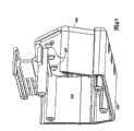
图36-38示出了现有电池组230。现有电池组230包括外壳242和由外壳242支撑的至少一个可再充电电池单元246(如图39-40所示)。在示出的结构中,现有电池组230是包括(参见图39-40)十五个串联连接的大约1.2V的电池单元246的18V电池组。电池单元246是可再充电电池单元化学物质类型的,诸如NiCd或NiMH。36-38 illustrate an existing
如图39-40所示,在现有电池组230中,每个电池单元246一般是圆柱形的且沿与圆柱形外电池单元壁平行的电池单元轴250延伸。在现有电池组230中,电池单元250互相平行。另外,在现有电池组230中,每个电池单元246具有大约两倍于电池单元直径254的电池单元长度252。在示出的结构中,每个电池单元246具有大约四十六毫米(46毫米)的长度和大约二十三毫米(23毫米)的直径。As shown in FIGS. 39-40, in
现有电池组230可连接至(参见图12)电池充电器38且电池充电器38可操作来对现有电池组230充电。现有电池组230可连接至诸如电动工具34的电气设备(如图11A所示),以对电动工具34供电。如图36-38所示,外壳242提供了支撑部分250,用于把现有电池组230支撑在电气设备上。在示出的结构中,支撑部分250提供了(参见图36)C形横截面,其可连接至电气设备上的互补T形横截面(电动工具34上的支撑部分(如图11B所示)和/或电池充电器38上的电池支撑部分(如图12所示))。The existing
现有电池组230包括(参见图36-37和39-40)可操作来把电池单元246电连接至电气设备中的电路的端接组件286。终端组件286包括正极电池终端298、接地终端302和感测终端306。如图39-40所示,终端298和302被连接至电池单元或系列电池单元246的相反末端。感测终端306被连接至(参见图40)电元件314,并且该电元件314在现有电池组230的电路中连接。在示出的结构中,电元件314是热敏器件或热敏电阻器,用于传递现有电池组230和/或电池单元246的温度。Existing
本发明提供了一种实质上减缓了上述和其它现有电池组中所存在的一个或多个独立问题的电池组。在一些方面和一些结构中,本发明提供了一种电池组,其包括两个被安置为彼此不平行关系的电池单元。在一些方面中,这两个电池单元被安置成彼此垂直的关系。The present invention provides a battery that substantially alleviates one or more of the independent problems of the above and other prior art batteries. In some aspects and some constructions, the present invention provides a battery pack that includes two battery cells disposed in a non-parallel relationship to each other. In some aspects, the two battery cells are positioned in a perpendicular relationship to each other.
更具体地说,在一些方面和一些结构中,本发明提供了一种包括外壳、沿第一电池单元轴延伸的第一电池单元和沿第二电池单元轴延伸的第二电池单元的电池组,第一电池单元和第二电池单元由外壳以其中第一电池单元轴与第二电池单元轴不平行的方向支撑。在一些方面和一些结构中,第一电池单元轴垂直于第二电池单元轴。More specifically, in some aspects and some constructions, the present invention provides a battery pack including a housing, a first battery cell extending along a first battery cell axis, and a second battery cell extending along a second battery cell axis , the first battery cell and the second battery cell are supported by the case in a direction in which the axis of the first battery cell is not parallel to the axis of the second battery cell. In some aspects and some constructions, the first battery cell axis is perpendicular to the second battery cell axis.
另外,在一些方面和一些结构中,本发明提供了一种组装电池组的方法,该方法包括提供电池组外壳、用该外壳支撑第一电池单元以及用该外壳以与第一电池单元不平行的关系支撑第二电池单元的步骤。在一些方面中,支撑第二电池单元的步骤包括以与第一电池单元垂直的关系支撑第二电池单元。Additionally, in some aspects and some constructions, the present invention provides a method of assembling a battery pack, the method comprising providing a battery pack housing, supporting a first battery cell with the housing, and supporting a first battery cell with the housing so that it is not parallel to the first battery cell. The relationship supports the second cell step. In some aspects, supporting the second battery cell includes supporting the second battery cell in perpendicular relationship to the first battery cell.
此外,在一些方面和一些结构中,本发明提供了一种电池组,其包括多个电池单元、用于感测多个电池单元的第一组的电压的传感器、用于感测多个电池单元的第二组的电压的传感器以及用于把第一组的电压与第二组的电压进行比较以确定多个电池单元中的一个电池单元是否等于或低于一电压的控制器。Furthermore, in some aspects and some constructions, the present invention provides a battery pack comprising a plurality of battery cells, a sensor for sensing a voltage of a first group of the plurality of battery cells, a sensor for sensing a voltage of a first group of the plurality of battery cells A sensor of the voltage of the second group of cells and a controller for comparing the voltage of the first group to the voltage of the second group to determine whether a battery cell of the plurality of cells is at or below a voltage.
此外,在一些方面和一些结构中,本发明提供了一种确定电池组的电池单元的电压的方法,该电池组包括多个电池单元,该方法包括感测多个电池单元的第一组的电压、感测多个电池单元的第二组的电压以及把第一组的电压与第二组的电压进行比较以确定多个电池单元中的一个电池单元是否等于或低于一电压的步骤。Additionally, in some aspects and some constructions, the present invention provides a method of determining the voltage of a battery cell of a battery pack comprising a plurality of battery cells, the method comprising sensing a voltage of a first group of the plurality of battery cells voltage, sensing a voltage of a second group of cells and comparing the voltage of the first group to the voltage of the second group to determine whether one of the cells is at or below a voltage.
另外,在一些方面和一些结构中,本发明提供了一种电池组,其包括外壳、由外壳支撑的电池单元、连接至该电池单元的FET以及与该FET为热传送关系的散热器。Additionally, in some aspects and some constructions, the present invention provides a battery pack that includes a housing, a battery cell supported by the housing, a FET connected to the battery cell, and a heat sink in heat transfer relationship with the FET.
此外,在一些方面和一些结构中,本发明提供了一种组装电池组的方法,该方法包括提供外壳、用该外壳支撑电池单元、用该外壳支撑FET、把该FET连接至该电池单元以及支撑与该FET处于热传送关系的散热器的步骤。Additionally, in some aspects and some constructions, the present invention provides a method of assembling a battery pack, the method comprising providing a housing, supporting a battery cell with the housing, supporting a FET with the housing, connecting the FET to the battery cell, and The step of supporting a heat sink in heat transfer relationship with the FET.
此外,在一些方面和一些结构中,本发明提供了一种电池组,其包括可由电气设备支撑的外壳、由外壳支撑且可连接至该电气设备的电池单元以及用于把该电池锁定至该电气设备的锁定组件。该锁定组件包括:锁定件,由外壳支撑,用于在该电池被锁定至电气设备的锁定位置与未锁定位置之间移动;致动器,由外壳支撑且可操作来使锁定件在锁定位置与未锁定位置之间移动;以及偏置件,可操作来把锁定件偏置向锁定位置,该偏置件被固定在致动器与外壳之间且使致动器保持在相对于外壳的位置上。Additionally, in some aspects and some constructions, the present invention provides a battery pack comprising a housing supportable by an electrical device, a battery cell supported by the housing and connectable to the electrical device, and a battery unit for locking the battery to the electrical device. Locking components for electrical equipment. The locking assembly includes a locking member supported by the housing for movement between a locked position in which the battery is locked to the electrical device and an unlocked position; an actuator supported by the housing and operable to place the locking member in the locked position and an unlocked position; and a biasing member operable to bias the locking member toward the locked position, the biasing member being fixed between the actuator and the housing and maintaining the actuator at a position relative to the housing position.
通过阅读具体的描述和附图,本领域的技术人员将对本发明的独立特征和独立优点更为清楚明了。The independent features and independent advantages of the present invention will become clearer to those skilled in the art by reading the detailed description and accompanying drawings.
附图说明Description of drawings
图1是电池组的正透视图。Fig. 1 is a front perspective view of a battery pack.
图2是如图1所示的电池组的俯视后透视图。FIG. 2 is a top rear perspective view of the battery pack shown in FIG. 1 .
图3是如图1所示的电池组的仰视后透视图。FIG. 3 is a bottom rear perspective view of the battery pack shown in FIG. 1 .
图4是如图1所示的电池组的俯视图。FIG. 4 is a top view of the battery pack shown in FIG. 1 .
图5是如图1所示的电池组的仰视图。FIG. 5 is a bottom view of the battery pack shown in FIG. 1 .
图6是如图1所示的电池组的正视图。FIG. 6 is a front view of the battery pack shown in FIG. 1 .
图7是如图1所示的电池组的后视图。FIG. 7 is a rear view of the battery pack shown in FIG. 1 .
图8是如图1所示的电池组的右视图。FIG. 8 is a right side view of the battery pack shown in FIG. 1 .
图9是如图1所示的电池组的左视图。FIG. 9 is a left side view of the battery pack shown in FIG. 1 .
图10是具体表现了本发明的各方面的电池组的另一结构的仰视图。Fig. 10 is a bottom view of another structure of a battery pack embodying aspects of the present invention.
图11A是与如图1所示的电池组一起使用的诸如电动工具的电气设备的透视图。11A is a perspective view of an electrical device, such as a power tool, used with the battery pack shown in FIG. 1 .
图11B是如图11A所示的电动工具的支撑部分的透视图。Fig. 11B is a perspective view of a support portion of the power tool shown in Fig. 11A.
图12是与如图1所示的电池组一起使用的诸如电池充电器的电气设备的透视图。FIG. 12 is a perspective view of an electrical device, such as a battery charger, for use with the battery pack shown in FIG. 1 .
图13是如图1所示的电池组的一部分的透视图且示出了电池单元和电池终端组件。13 is a perspective view of a portion of the battery pack shown in FIG. 1 and showing battery cells and battery terminal assemblies.
图14是如图13所示的电池单元和电池终端组件的俯视图。FIG. 14 is a top view of the battery cell and battery terminal assembly shown in FIG. 13 .
图15是如图13所示的电池单元和电池终端组件的仰视图。FIG. 15 is a bottom view of the battery cell and battery terminal assembly shown in FIG. 13 .
图16是如图13所示的电池单元和电池终端组件的正视图。FIG. 16 is a front view of the battery cell and battery terminal assembly shown in FIG. 13 .
图17是如图13所示的电池单元和电池终端组件的后视图。FIG. 17 is a rear view of the battery cell and battery terminal assembly shown in FIG. 13 .
图18是如图13所示的电池单元和电池终端组件的右视图。FIG. 18 is a right side view of the battery cell and battery terminal assembly shown in FIG. 13 .
图19是如图13所示的电池单元和电池终端组件的左视图。FIG. 19 is a left side view of the battery cell and battery terminal assembly shown in FIG. 13 .
图20是比如图1所示的电池组的电池组的元件的示意图。20 is a schematic illustration of elements of a battery pack such as the battery pack shown in FIG. 1 .
图21是电池组的元件的另一示意图。Figure 21 is another schematic illustration of the components of the battery pack.
图22是电池组的元件的又一示意图。22 is yet another schematic illustration of the components of the battery pack.
图23是电池组的元件的再一示意图。Figure 23 is yet another schematic illustration of the components of the battery pack.
图24是移去了其一部分的如图1所示的电池组的一部分的透视图。Fig. 24 is a perspective view of a portion of the battery pack shown in Fig. 1 with a portion thereof removed.
图25是移去了其一部分的如图1所示的电池组的一部分的透视图。Fig. 25 is a perspective view of a portion of the battery pack shown in Fig. 1 with a portion thereof removed.
图26是移去了其一部分的如图1所示的电池组的一部分的透视图。Fig. 26 is a perspective view of a portion of the battery pack shown in Fig. 1 with a portion thereof removed.
图27是如图26所示的电池组的这部分的俯视图。FIG. 27 is a top view of the portion of the battery pack shown in FIG. 26 .
图28包括如图26所示的电池组的部分的视图。FIG. 28 includes views of portions of the battery pack shown in FIG. 26 .
图29是移去了其一部分的如图1所示的电池组的一个部分的分解透视图。Fig. 29 is an exploded perspective view of a portion of the battery pack shown in Fig. 1 with a portion thereof removed.
图30是移去了其一部分的如图1所示的电池组的一部分的后透视图。30 is a rear perspective view of a portion of the battery pack shown in FIG. 1 with a portion thereof removed.
图31是如图30所示的电池组的这部分的另一后透视图。FIG. 31 is another rear perspective view of the portion of the battery pack shown in FIG. 30 .
图32是移去了其一部分的如图1所示的电池组的一部分的分解透视图。Fig. 32 is an exploded perspective view of a portion of the battery pack shown in Fig. 1 with a portion thereof removed.
图33是如图32所示的电池组的这部分的透视图。FIG. 33 is a perspective view of the portion of the battery pack shown in FIG. 32 .
图34是如图33所示的电池组的这部分的放大透视图。FIG. 34 is an enlarged perspective view of the portion of the battery pack shown in FIG. 33 .
图35包括移去了其一部分的如图1所示的电池组的部分的视图。35 includes a view of a portion of the battery pack shown in FIG. 1 with a portion thereof removed.
图36是现有电池组的后透视图。Fig. 36 is a rear perspective view of a conventional battery pack.
图37是如图36所示的电池组的正透视图。FIG. 37 is a front perspective view of the battery pack shown in FIG. 36 .
图38是如图36所示的电池组的左视图。Fig. 38 is a left side view of the battery pack shown in Fig. 36 .
图39是如图36所示的电池组的一部分的透视图且示出了电池单元和电池终端组件。39 is a perspective view of a portion of the battery pack shown in FIG. 36 and showing battery cells and battery terminal assemblies.
图40是如图39所示的电池单元和电池终端组件的右视图。FIG. 40 is a right side view of the battery cell and battery terminal assembly shown in FIG. 39 .
图41是另一电池组的正透视图。Fig. 41 is a front perspective view of another battery pack.
图42是如图41所示的电池组的右视图。Fig. 42 is a right side view of the battery pack shown in Fig. 41 .
图43是如图41所示的电池组的左视图。Fig. 43 is a left side view of the battery pack shown in Fig. 41 .
图44是如图41所示的电池组的俯视图。FIG. 44 is a top view of the battery pack shown in FIG. 41 .
图45是如图41所示的电池组的仰视后透视图。FIG. 45 is a bottom rear perspective view of the battery pack shown in FIG. 41. FIG.
图46是如图41所示的电池组的正视图。Fig. 46 is a front view of the battery pack shown in Fig. 41 .
图47是如图41所示的电池组的后视图。Fig. 47 is a rear view of the battery pack shown in Fig. 41 .
图48是又一电池组的正透视图。Figure 48 is a front perspective view of yet another battery pack.
图49是如图48所示的电池组的右视图。Fig. 49 is a right side view of the battery pack shown in Fig. 48 .
图50是如图48所示的电池组的左视图。Fig. 50 is a left side view of the battery pack shown in Fig. 48 .
图51是如图48所示的电池组的俯视图。FIG. 51 is a top view of the battery pack shown in FIG. 48 .
图52是如图48所示的电池组的仰视后透视图。FIG. 52 is a bottom rear perspective view of the battery pack shown in FIG. 48 .
图53是如图48所示的电池组的正视图。Fig. 53 is a front view of the battery pack shown in Fig. 48 .
图54是如图48所示的电池组的后视图。FIG. 54 is a rear view of the battery pack shown in FIG. 48 .
图55是与比如电动工具的第一电气设备一起使用的电池组的透视图。55 is a perspective view of a battery pack for use with a first electrical device, such as a power tool.
图56是与比如电动工具的第二电气设备一起使用的电池组的透视图。56 is a perspective view of a battery pack for use with a second electrical device, such as a power tool.
图57是电池组的一部分的透视图且示出了电池单元。Fig. 57 is a perspective view of a portion of the battery pack and showing the battery cells.
图58是电池组的一部分的透视图且示出了电池单元、终端、末端帽和线路。Figure 58 is a perspective view of a portion of a battery pack and showing the battery cells, terminals, end caps and wiring.
图59是如图58所示的电池组的这部分的后透视图。FIG. 59 is a rear perspective view of the portion of the battery pack shown in FIG. 58. FIG.
图60是如图58所示的电池组的这部分的右视图。FIG. 60 is a right side view of the portion of the battery pack shown in FIG. 58 .
图61是如图58所示的电池组的这部分的左视图。FIG. 61 is a left side view of the portion of the battery pack shown in FIG. 58 .
图62是如图58所示的电池组的这部分的正视图。FIG. 62 is a front view of the portion of the battery pack shown in FIG. 58 .
图63是如图58所示的电池组的这部分的后视图。FIG. 63 is a rear view of the portion of the battery pack shown in FIG. 58. FIG.
图64是如图58所示的电池组的这部分的俯视图。FIG. 64 is a top view of the portion of the battery pack shown in FIG. 58 .
图65是电池组的一部分的透视图且示出了末端帽。Fig. 65 is a perspective view of a portion of a battery pack showing end caps.
图66是电池组的外壳的一部分的部分侧透视图。66 is a partial side perspective view of a portion of the housing of the battery pack.
图67是如图66所示的外壳的这部分的部分正透视图。FIG. 67 is a partial front perspective view of the portion of the housing shown in FIG. 66. FIG.
图68-69是电池组的元件的另一示意图。68-69 are another schematic illustration of elements of a battery pack.
在详细描述本发明的任何实施例之前,应当理解,本发明并不把其申请限定于下面说明中所描述的或下面附图中所示出的结构的细节和元件的布置。本发明能够有其它的实施例且能够以各种方式被实践或执行。另外,应当理解,此处所使用的措辞和术语只用于描述的目的且不应当被认为是限定性的。“包括(including)”、“包含(comprising)”或“具有(having)”及其变型的使用应当包含在此所列出的项目及其等同物以及附加的项目。Before any embodiments of the invention are described in detail, it is to be understood that the invention is not limited in application to the details of construction and the arrangement of elements described in the following description or shown in the following drawings. The invention is capable of other embodiments and of being practiced or carried out in various ways. Also, it is to be understood that the phraseology and terminology used herein are for the purpose of description only and should not be regarded as limiting. Use of "including," "comprising," or "having" and variations thereof shall encompass the items listed herein and equivalents thereof as well as additional items.
具体实施方式Detailed ways
具体表现了本发明的各方面的电池组30如图1-9所示。现有电池组30可以连接至诸如无绳电动工具34的电气设备(如图11A所示),以选择性地对电动工具34供电。电池组30可以从电动工具34拆卸且可以由电池充电器38(如图8所示)再充电。A
如图1-9所示,电池组30包括外壳42和由外壳42支撑的至少一个可再充电电池单元46(如图13-19所示)。在示出的结构中,电池组30可以是包括串联连接的五个大约4.2V的电池单元46a、46b、46c、46d、和46e的21V的电池组。在其它结构(未示出)中,电池组30可以具有另一标称电池电压,诸如9.6V、12V、14.4V、24V等,以对电气设备供电,以及由电池充电器38充电。应当理解,在其它结构(未示出)中,电池单元46可以具有不同的标称电池单元电压和/或以另一设置连接,诸如并联或并联/串联组合。As shown in FIGS. 1-9, the
电池单元46可以是任何可再充电电池单元化学物质类型的,例如镍-镉(NiCd)、镍-金属氢化物(NiMH)、锂(Li)、锂-离子(Li-ion)、其它锂基化学物质,其它可再充电电池单元化学物质等。在示出的结构中,电池单元46可以是锂-离子电池单元。例如,电池单元46可以具有锂-钴(Li-Co)、锂-锰(Li-Mn)尖晶石、锂-锰镍等的化学物质。The
如图13-20所示,在电池组30中,每个电池单元46a-46e一般可以为圆柱形且可以沿与圆柱形外电池单元壁平行的电池单元轴50a-50e延伸。另外,在电池组30中,每个电池单元46可以具有多于两倍且几乎三倍于电池单元直径54的电池单元长度52。在示出的结构和一些方面中,每个电池单元可以具有大约二十六毫米(26毫米)的直径和至少大约六十毫米(60毫米)的长度。在一些结构中,每个电池单元46可以具有大约六十五毫米(65毫米)的长度。在一些结构中,每个电池单元46可以具有大约七十毫米(70毫米)的长度。As shown in FIGS. 13-20, in
电池单元46被排列为电池单元46a、46b和46c的第一组56和电池单元46d和46e的第二组58。在第一组56中,电池单元轴50a、50b和50c互相平行。在第二组58中,电池单元轴50d和50e彼此平行。但是,排列电池组56和58使得电池单元46a、46b和46c与电池单元46d和46e不平行。在示出的结构中,例如,电池单元46a、46b和46c可以与电池单元46d和46e垂直。The
排列电池单元46以降低电池单元46之间的热传送和改善从电池单元46收集和除去热量的能力。通过这样的方式,电池单元46能够被保持在适当的温度工作范围内,以使用更长的时间。还排列电池单元46以提供空间的有效利用和保持相对较小的电池组尺寸。The
如图1-4和图7所示,外壳42能够提供用于把电池组30支撑在诸如电动工具34或电池充电器38的电气设备上的支撑部分60。在示出的结构中,支撑部分60提供了可连接至电气设备上的互补T形横截面支撑部分的C形横截面(参见图7)。As shown in FIGS. 1-4 and 7 ,
电池组30还可以包括(参见图1-4、8-9、21、24-25和30-38)锁定组件74,其可操作来把电池组30锁定至电气设备,诸如锁定至电动工具34和/或电池充电器。锁定组件34包括可在锁定位置与未锁定位置之间移动的锁定件78,其中在锁定位置上,锁定件78与电气设备上的对应锁定件接合,以把电池组30锁定至电气设备。锁定组件74还包括用于使锁定件78在锁定位置与未锁定位置之间移动的致动器82。致动82具有用于由操作者接合的大表面,以更加容易地开启锁定组件74。另外,支撑致动器82以减小开启锁定组件74所需的夹持力。The
如图30-38所示,偏置件83把锁定件78偏置向锁定位置。在示出的结构中,每个偏置件83是置于致动器82与外壳42之间的片弹簧,用于把锁定件78偏置到锁定位置。As shown in FIGS. 30-38, biasing
每个偏置件83被固定在致动器82与外壳42之间且操作来使致动器82(和锁定件78)保持在预定位置上且限定致动器82(和锁定件78)相对于外壳42的不需要的移动。具体地说,偏置件83限定致动82(和锁定件78)在与锁定位置和开锁位置之间的运动方向垂直的方向(即图35的横截面图中的向上方向)上的移动,以防止致动器82和/或锁定件78被绑定在外壳42上或被制止以所需的方式移动来操作锁定组件74。Each biasing
如图32和35所示,偏置件83包括与外壳42接合的外壳腿84,用于把偏置件83向下推(在图35的左横截面图中)。偏置件83还包括(参见图35的右横截面图)与致动器83接合的致动器腿85,以在锁定组件74和电池组30的操作期间把致动器82(和锁定件78)牵引并保持在正向下位置上(在图35的横截面图中)。As shown in Figures 32 and 35, biasing
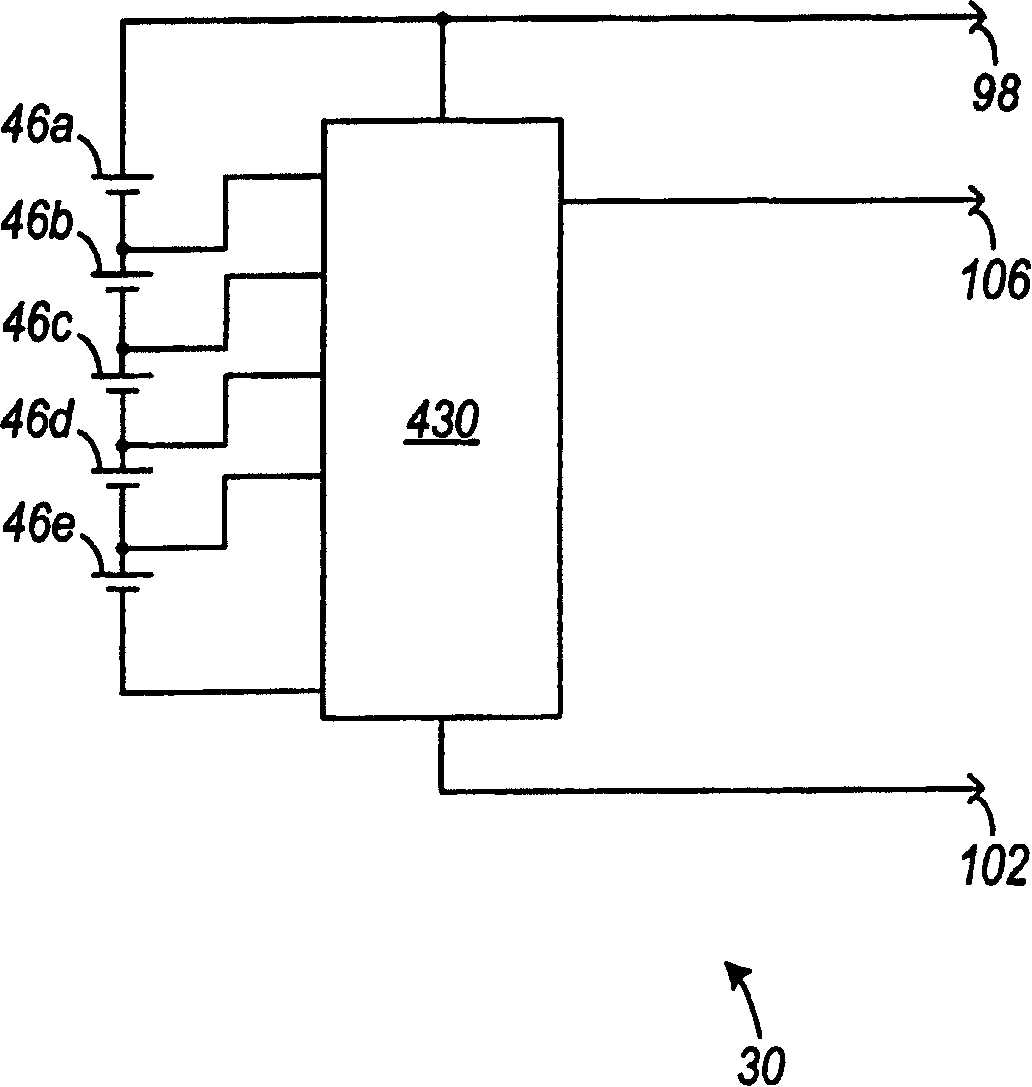
电池组30包括(参见图1-5、7、13-14和17-20)可操作来把电池单元46电连接至电气设备中的电路的端接组件86。终端组件86包括(参见图1-3)正极电池终端98、接地终端102和感测终端106。如图20示意性所示的,终端98和102被连接至电池单元或系列电池单元46的相反末端。
感测终端106可以被连接至一个或多个电元件,例如识别元件(即电阻器),用于传递诸如电池单元46的化学物质、电池组30的标称电压等的对电池组30的特征的识别,或者被连接至热敏器件或热敏电阻器,用于传递电池组30和/或电池单元46的温度。应当理解,在其它结构(未示出)中,电元件可以是其它类型的电元件且可能传递其它关于电池组30和/或一个或多个电池单元46的特征或消息。还应当理解,结合电元件而使用的“通信(communication)”和“传递(communicate)”也可以涵盖具有由能够确定该电元件的状况或状态的传感器或器件所感测到的状况或状态或处于所述状况或状态下的电元件。The
在一些结构和一些方面中,感测终端106可以被连接至电路430,如图21-23和68-69所示。电路430可以被电连接至一个或多个电池单元46且可以被电连接至终端块86的一个或多个电池终端。在一些结构中,电路430可以包括用于增强电池组30的性能的元件。在一些结构中,电路430可以包括用于监视电池特征、用于提供电压检测、用于存储电池特征、用于显示电池特征、用于通知用户特定的电池特征、用于暂停电池50内的电流、用于检测电池组30、电池单元46等的温度、用于传送来自电池30和/或在其中的热量、以及用于当在一个或多个电池单元46内检测到不平衡时提供平衡方法的元件。在一些结构和一些方面中,电路430包括电压检测电路、升压电路、充电状态指示器等。在一些结构中,电路430可以被耦合至印制电路板(PCB)145。在其它结构中,电路430可以被耦合至如在下面所论述的柔性电路445。在一些结构中,柔性电路445可以卷绕在一个或多个电池单元46周围或卷绕外壳42的内部,这在下面论述。In some constructions and some aspects, the
在一些结构中,电路430也可以包括微处理器440。微处理器440可以监视各种电池组参数(例如电池组的当前充电状态、电池单元的当前充电状态、电池组温度、电池单元温度等),可以存储各种电池组参数和特征(包括除了这些参数之外的电池组标称电压、化学物质等),可以控制电路430内的各种电元件以及可以进行与诸如电动工具、电池充电器等的其它电气设备的通信。在一些结构中,微处理器440可以监视每个电池单元的当前充电状态以及识别何时发生不平衡(例如,电池单元的当前充电状态比平均电池单元充电状态高一定的量或比平均电池单元充电状态低一定的量)。In some constructions, the
在一些结构和一些方面中,电路430可以包括电压检测电路459。在一些结构中,电压检测电路459可以包括形成电阻分压器网络的多个电阻器460。如示出的结构所示,多个电阻器460可以包括电阻器460a-d。多个电阻器460可以电连接至一个或多个电池单元46a-e和多个晶体管465。在示出的结构中,多个晶体管465可以包括晶体管465a-d。在一些结构中,多个电阻器460中所包括的电阻器数目可以等于多个晶体管465中所包括的晶体管数目。In some constructions and some aspects,
在一些结构中,当微处理器440处于激活模式时,电池组30和/或电池单元46的电压特征可以由微处理器440通过多个电阻器460读出。在一些结构中,微处理器440可以通过断开一个或多个晶体管470(即晶体管470变成不导通的)来启动电压读数事件。当一个或多个晶体管470不导通时,晶体管265a-d变成导通的且微处理器440可以作出关于电池组30和/或电池单元46的电压测量。在电池组30中包括多个晶体管465可以降低从电池组30中引出的寄生电流,因为晶体管465只是周期性地导通的。In some constructions, the voltage characteristics of the
在一些结构中,微处理器440可以监视每个电池单元46的电压且如果发生不平衡则平衡电池单元46。如前面所论述的,电池组30可以包括用于提供电池单元46的电压测量的多个电阻器460。排列多个电阻器460使得微处理器440可以近乎同时测量每个电池单元46a-e的电压。在一些结构中,微处理器440在一个或多个电池单元46达到大约1V时检测电池组30内的不平衡。In some constructions, the
在一些结构和一些方面中,电池组30可以在已检测到不平衡时通过平衡电路459来重新平衡电池单元46。在一些结构中,电池组30在电池组30处于放电操作或步骤中或当电池组30没有提供放电电流或接收充电电流时重新平衡电池单元46。在一些结构中,平衡电路459可以包括多个电阻器460和多个晶体管465。在一些结构中,微处理器440在电池单元46之间的平衡比率R不再处于可接受范围内时通过开关180停用电池30(例如中断电池操作、制止电池操作等)。在停用电池组30之后,微处理器确定哪个或那些电池单元46不平衡(“低电压电池单元”)。In some constructions and some aspects,
在一些结构中,微处理器440启动或接通各晶体管,诸如晶体管465a-d,其被电连接至那些不具有低的当前充电状态的电池单元46(即具有比低电压电池单元更高的当前充电状态的电池单元)。微处理器440开始对高的当前充电状态的电池单元46的受控放电。例如,微处理器通过各晶体管控制将从平衡电池单元46流出的小放电电流。微处理器440继续在整个受控放电过程中作出对电池单元46的电压测量。在较高的充电状态的电池单元46的当前充电状态降低至大约等于先前的低电压电池单元的时候,微处理器440结束受控放电过程。In some constructions, the
电路430和电池组30的元件,例如FET 480、散热器485、热敏电阻器450、燃料计170(470)(包括一个或多个发光二极管470a-d)、用于启动燃料计470的按钮460、微处理器440等,在图20-29中更详细地示出。对于一些结构和一些方面,电池组30的这些及其它附加独立特征和结构以及电池组30的其它操作在于2003年11月20日申请的序列号为10/720,027且标题为“System and method of batteryprotection(电池保护的系统和方法)”的美国专利申请(代理人卷号066042-9536-01)中进行了更详细地描述。Components of
如图8所示,电池充电器38可连接至电池组30且可操作来对电池组30充电。电池充电器38包括充电器外壳122,其提供了在其上面支撑电池组30的支撑部分124,电池充电器38还包括充电电路126(在图12中示意性示出),其由外壳122支撑且可连接至电源(未示出)。充电电路126可通过充电器终端组件128连接至电池组30的终端组件86且可操作来把功率传送至电池组30,以对电池单元46充电。As shown in FIG. 8 , a battery charger 38 is connectable to the
在一些结构和一些方面中,充电电路126以类似于在于2002年9月24日颁发的美国专利No.6,456,035以及于2001年4月24日颁发的美国专利No.6,222,343所描述的方式操作,以对电池组30充电,在这里完全部包括上述专利的内容并引入作为参考。In some constructions and some aspects, charging circuit 126 operates in a manner similar to that described in U.S. Patent No. 6,456,035, issued September 24, 2002, and U.S. Patent No. 6,222,343, issued April 24, 2001, to Charging the
对于一些结构和一些方面,电池充电器38的附加的独立特征、结构和操作在于2003年11月20日申请的序列号为10/720,027且标题为“System and method of battery protection(电池保护的系统和方法)”的美国专利申请(代理人卷号066042-9536-01)以及于2003年11月20日申请的序列号为10/719,680其标题为“Method and system ofbattery charging(电池充电的方法和系统)”的美国专利申请(代理人卷号066042-9538-01)中进行了更详细地描述。For some constructions and some aspects, additional independent features, construction and operation of the battery charger 38 are contained in the application serial no. 10/720,027 filed November 20, 2003 and entitled "System and method of battery protection" and method)" (Attorney Docket No. 066042-9536-01) and serial number 10/719,680 filed November 20, 2003, entitled "Method and system of battery charging (method and system of battery charging) and System)" in U.S. Patent Application (Attorney Docket No. 066042-9538-01) is described in more detail.
电池组30可连接至诸如电动工具34的电气设备(如图11A所示),以对电动工具34供电。电动工具34包括支撑电马达184(示意性示出)的外壳182,其中电马达184通过(参见图11B)电动工具终端组件186电连接至电池组30,使得马达184由电池组30选择性地供电。外壳182提供了(参见图11B)在其上面支撑电池组30的支撑部分186。支撑部分186一般具有与电池组30的支撑部分60的C形横截面互补的T形横截面。支撑部分186也限定了锁定槽188(所示的一个),在该锁定槽188中可以接合锁定件78以把电池组30锁定至电动工具34。The
具体表现了本发明的各方面的电池组30A的另一结构在图10中示出。共同的元件由相同的参考数字“A”表示。Another configuration of a
如前所述,电池组30可以包括比所示的实施例更多或更少的电池单元46,且可以具有比所示的和所描述的结构中更高或更低的标称电压。例如,具有较高标称电压的电池组30B的一个结构如图41-47所示。共同的元件由相同的参考数字“B”表示。电池组30C的又一结构如图48-54所示。共同的元件由相同的参考数字“C”表示。As previously mentioned, the
除非有指定,在下文中,电池组30可以指电池组30的各种结构(例如电池组30、电池组30A、电池组30B和电池组30C)。另外,除非有指定,否则电池组30B可以同时指电池组30B和电池组30C。Unless otherwise specified, hereinafter, the
在一些结构中,可以设置电池组30以把功率传送至诸如各种电动工具、电池充电器等的各种电气设备并接收来自它们的功率。在其它结构中,可以设置电池组30以传送功率至各种高功率电气设备,例如:包括在制造和组装中使用的由电驱动的工具的多种电动工具;包括在农业应用中使用的工具的草坪和花园用设备;手提照明设备,信号发送设备和手电筒;包括由电驱动的小型摩托车、机动自行车、机动卡车等的机动交通工具;真空吸尘器及其它由电驱动的家庭和商业应用、工具和设备;由电驱动的玩具;遥控飞机,机动车及其它交通工具以及辅助发动机等。在一些结构中,例如在图55和56中所示的结构,电池组30可以提供功率给各种电动工具,例如主驱动钻机300、圆锯305等。在一些结构中,电池组30可以对具有高放电电流速率的各种电动工具(包括主驱动钻机300和圆锯305)供电。例如,电池组30可以提供等于或大于大约20A的平均放电电流且可以具有大约3.0A-h的安培-小时容量。In some constructions,
在一些结构中,诸如电池组30B的电池组30可以包括七个电池单元346a-g(如图57所示)。在一些结构中,电池单元346a-g可以类似于电池组30中所包括的电池单元46a-e。在一些结构中,电池单元346a-g在重量、尺寸、标称电压、化学物质等方面上可以不同于电池单元46a-e。例如,在一个结构中,电池单元346a-g可以具有锂离子的电池单元化学物质,例如锂-锰尖晶石、锂-锰镍或锂钴。在一些结构中,每个电池单元346a-g可以具有大约3.6V的标称电压。在其它结构中,每个电池单元346a-g可以具有大约4V的标称电压,并且在其它结构中,每个电池单元346a-g可以具有大约4.2V的标称电压。在一些结构中,电池组30B可以包括七个电池单元346a-g,以及可以具有大约28V的标称电压。在其它结构中,电池组30B可以包括七个电池单元346a-g,并且可以具有大约25V的标称电压。In some constructions, a
还可以以任何合适的方式电连接电池单元346a-g,例如串联布置、并联布置、部分串联布置(例如电池单元346a-g中的一些以串联的布置连接)、部分并联布置(例如电池单元346a-g中的一些以串联的布置连接)、串联、并联、部分串联或部分并联布置的组合。在一个结构中,电池单元346a-g以串联布置电连接。电池单元346a-g可以通过导电带450电连接。例如,导电带450可以把第一电池单元346a的负极末端连接至第二电池单元346b的正极末端。而且,另一导电带450可以把第二电池单元346b的负极末端连接至第三电池单元346c的正极末端。The
如图58-65所示,诸如电池组30B的电池组30也可以包括端帽布置505。在一些结构中,端帽布置可以用于隔开电池单元346。端帽布置505包括第一端帽510和第二端帽515。第一和第二端帽510和515可以通过连接部分520连接。在一些结构中,连接部分520可以是铰链。在一些结构中,端帽布置505不包括连接部分520。每个端帽510和515可以部分限定一个或多个腔530(如图65所示)。电池单元346的末端可以置于腔530内。在其它结构中,第一端帽510和第二端帽520中的每个均包括七个腔530a-g,分别用于安置七个电池单元346a-g。As shown in FIGS. 58-65 , a
在示出的结构中,第一端帽510被安置在电池单元346的布置的第一末端490上(如图57所示),并且第二端帽515被安置在电池单元346的布置的第二末端495上。如前面所提到的,每个电池单元346a-g的每个末端可以被安置在第一和第二端帽510和515的各腔530a-g内。在电池单元346被置于该腔530内的时候,每个端帽510和515可以限定腔530a-g,以在电池单元346之间创建缝隙或间隔。这可以通过允许空气在电池单元346之间的缝隙和间隔之间循环来在电池组30B内实现更大的散热效果。In the illustrated construction, a
在一些结构中,第一端帽510和第二端帽515可以进一步限定孔450。孔450可以容纳导电带450,以把一个电池单元346电连接至另一电池单元346。In some constructions,
在一些结构和一些方面中,端帽布置505还可以包括柔性电路445。在一些结构中,柔性电路445可以与第一端帽510、第二端帽515、连接部分520或其组合集成。在其它结构中,端帽布置505可以限定一个或多个用于支撑该柔性电路的区域。在其它结构中,柔性电路445可以被固定至端帽布置505。如示出的结构所示,柔性电路445可以部分地卷绕电池单元346周围。In some constructions and some aspects,
在所示的结构中,端帽布置505可以包括用于把柔性电路445电连接至PCB 145B的连接器560。在这个结构中,PCB 145B和柔性电路445每个均可以包括电池组30B中所包括的电路430的一部分。In the illustrated construction, the
在一些结构和一些方面中,电池组30可以包括缓冲件或减震器640。如图66和67所示,电池外壳42B的内面645可以包括一个或多个缓冲件640。在一些结构中,缓冲件640可以与外壳42B组成一体。在其它结构中,缓冲件640可以附接或固定至外壳42B的内面。在其它结构中,缓冲件640可以被连接至一个或多个电池单元346或被连接至部分围绕电池单元346的端帽布置505。在一些结构中,缓冲件645可以通过限定传送至电池单元346的能量的量来在冲击期间缓冲能量且在冲击期间保护电池单元346。缓冲件645可以包括任何热塑性橡胶,例如聚丙烯RPT 100FRHI(例如高冲击阻燃型)。In some constructions and some aspects,
本发明的一个或多个独立特征或独立优点将在权利要求中陈述。One or more independent features or independent advantages of the invention are set out in the claims.
Claims (9)
Applications Claiming Priority (14)
| Application Number | Priority Date | Filing Date | Title |
|---|---|---|---|
| US52371203P | 2003-11-19 | 2003-11-19 | |
| US52371603P | 2003-11-19 | 2003-11-19 | |
| US60/523,716 | 2003-11-19 | ||
| US60/523,712 | 2003-11-19 | ||
| US10/720,027 | 2003-11-20 | ||
| US10/719,680 | 2003-11-20 | ||
| US10/720,027 US7157882B2 (en) | 2002-11-22 | 2003-11-20 | Method and system for battery protection employing a selectively-actuated switch |
| US10/719,680 US7176654B2 (en) | 2002-11-22 | 2003-11-20 | Method and system of charging multi-cell lithium-based batteries |
| US10/721,800 US7253585B2 (en) | 2002-11-22 | 2003-11-24 | Battery pack |
| US10/721,800 | 2003-11-24 | ||
| US57427804P | 2004-05-24 | 2004-05-24 | |
| US60/574,278 | 2004-05-24 | ||
| US57461604P | 2004-05-25 | 2004-05-25 | |
| US60/574,616 | 2004-05-25 |
Publications (2)
| Publication Number | Publication Date |
|---|---|
| CN1619876A CN1619876A (en) | 2005-05-25 |
| CN1619876B true CN1619876B (en) | 2010-11-10 |
Family
ID=34624153
Family Applications (1)
| Application Number | Title | Priority Date | Filing Date |
|---|---|---|---|
| CN2004100824366A Expired - Lifetime CN1619876B (en) | 2003-11-19 | 2004-09-21 | Battery |
Country Status (4)
| Country | Link |
|---|---|
| JP (17) | JP4624012B2 (en) |
| CN (1) | CN1619876B (en) |
| DE (1) | DE102004030037B4 (en) |
| GB (6) | GB2420032A (en) |
Families Citing this family (67)
| Publication number | Priority date | Publication date | Assignee | Title |
|---|---|---|---|---|
| US6525511B2 (en) | 2000-08-11 | 2003-02-25 | Milwaukee Electric Tool Corporation | Adapter for a power tool battery |
| US7443137B2 (en) | 2000-08-11 | 2008-10-28 | Milwaukee Electric Tool Corporation | Adapter for a power tool battery |
| DE102006042603A1 (en) | 2006-09-11 | 2008-03-27 | Robert Bosch Gmbh | loader |
| JP4998846B2 (en) * | 2007-01-18 | 2012-08-15 | 日立工機株式会社 | Cordless power tool |
| JP4922031B2 (en) * | 2007-03-19 | 2012-04-25 | 日立工機株式会社 | Portable tools |
| JP2008236881A (en) * | 2007-03-19 | 2008-10-02 | Hitachi Koki Co Ltd | Charger |
| JP5370709B2 (en) * | 2007-10-29 | 2013-12-18 | 日立工機株式会社 | Battery pack and electric tool equipped with the same |
| JP4104648B1 (en) * | 2007-09-13 | 2008-06-18 | 和征 榊原 | Battery pack |
| CN104103851B (en) * | 2007-09-14 | 2018-10-09 | A123系统有限责任公司 | Lithium rechargable battery with the reference electrode for state of health monitoring |
| JP2009289578A (en) * | 2008-05-29 | 2009-12-10 | Makita Corp | Battery pack of electric tool |
| JP2010040226A (en) * | 2008-08-01 | 2010-02-18 | Hitachi Koki Co Ltd | Battery pack for electric tools |
| JP5365108B2 (en) * | 2008-09-04 | 2013-12-11 | ミツミ電機株式会社 | Semiconductor integrated circuit |
| EP2337485B1 (en) | 2008-10-16 | 2016-09-21 | Royal Appliance Mfg. Co. | Battery powered cordless vacuum cleaner |
| JP5827565B2 (en) | 2008-11-07 | 2015-12-02 | サクティスリー, インク.Sakti3, Inc. | Method for manufacturing and structuring multiple electrochemical cells and energy collecting elements in an integrated structure |
| JP5436850B2 (en) * | 2008-12-19 | 2014-03-05 | 株式会社マキタ | Power tool battery pack |
| CN102301246B (en) * | 2009-01-27 | 2014-09-17 | 创科电动工具科技有限公司 | Battery pack with high and low current discharge terminals |
| KR20120003432A (en) | 2009-03-31 | 2012-01-10 | 산요덴키가부시키가이샤 | Battery Modules, Battery Systems, and Electric Vehicles |
| JP2011163847A (en) * | 2010-02-08 | 2011-08-25 | Denso Corp | Battery voltage monitoring apparatus |
| JP5461221B2 (en) | 2010-02-12 | 2014-04-02 | 株式会社マキタ | Electric tool powered by multiple battery packs |
| JP5567956B2 (en) * | 2010-09-16 | 2014-08-06 | 矢崎総業株式会社 | Cell voltage equalization device for multiple assembled batteries |
| JP5579046B2 (en) | 2010-12-27 | 2014-08-27 | 株式会社マキタ | Electric tool equipment |
| JP2012183611A (en) * | 2011-03-07 | 2012-09-27 | Makita Corp | Electric power tool having a plurality of secondary battery cells as power source |
| US20130026990A1 (en) * | 2011-07-27 | 2013-01-31 | Joy Ride Technology Co., Ltd. | Charge system for series connected rechargeable batteries |
| DE102011086799A1 (en) * | 2011-11-22 | 2013-05-23 | Robert Bosch Gmbh | System with a hand tool case and a hand tool battery |
| JP2015028839A (en) * | 2011-11-25 | 2015-02-12 | 三洋電機株式会社 | Battery pack |
| KR101897822B1 (en) * | 2011-12-02 | 2018-09-13 | 삼성에스디아이 주식회사 | Battery pack |
| JP2014050234A (en) * | 2012-08-31 | 2014-03-17 | Hitachi Koki Co Ltd | Power supply device |
| JP6098117B2 (en) | 2012-10-31 | 2017-03-22 | 日立工機株式会社 | Portable tools |
| JP5605588B2 (en) * | 2012-12-21 | 2014-10-15 | 日立工機株式会社 | Battery pack and electric tool equipped with the same |
| JP2014148018A (en) * | 2013-02-01 | 2014-08-21 | Makita Corp | Hand-held electric polisher |
| JP2014148017A (en) * | 2013-02-01 | 2014-08-21 | Makita Corp | Hand-held electric cutter |
| JP6133103B2 (en) * | 2013-04-04 | 2017-05-24 | 株式会社マキタ | Battery pack for electric tools |
| KR101529551B1 (en) * | 2013-08-12 | 2015-06-19 | 주식회사 아이티엠반도체 | Battery protecting device for replaceable secondary battery |
| JP6103237B2 (en) * | 2013-10-24 | 2017-03-29 | 株式会社豊田自動織機 | Battery pack |
| JP6103238B2 (en) * | 2013-10-24 | 2017-03-29 | 株式会社豊田自動織機 | Battery pack |
| JP2014100785A (en) * | 2014-01-15 | 2014-06-05 | Makita Corp | Power tool using plural battery packs as power source |
| GB201403971D0 (en) * | 2014-03-06 | 2014-04-23 | 7Rdd Ltd | Portable power supply improvements |
| WO2015166908A1 (en) * | 2014-04-30 | 2015-11-05 | 日立工機株式会社 | Cell pack, charging device, and electric tool |
| EP3806272A1 (en) * | 2014-05-18 | 2021-04-14 | Black & Decker Inc. | Power tool system |
| JP6282546B2 (en) * | 2014-07-11 | 2018-02-21 | 株式会社マキタ | Electric tool |
| JP6514866B2 (en) * | 2014-08-29 | 2019-05-15 | 株式会社マキタ | Rechargeable electric device |
| KR102316436B1 (en) * | 2014-11-17 | 2021-10-22 | 삼성전자주식회사 | Method for controlling different kind of battery cells and electronic device thereof |
| CN104362370A (en) * | 2014-11-25 | 2015-02-18 | 上海动力储能电池系统工程技术有限公司 | Lithium manganate lithium ion battery and preparation method thereof |
| EP3278380B1 (en) * | 2015-04-03 | 2020-09-16 | ConMed Corporation | Autoclave tolerant battery powered motorized surgical hand piece tool |
| CN104868571A (en) * | 2015-05-24 | 2015-08-26 | 中煤张家口煤矿机械有限责任公司 | Charger specialized for battery |
| JP6686341B2 (en) * | 2015-09-18 | 2020-04-22 | マックス株式会社 | Rechargeable tool |
| CN108698217B (en) * | 2016-02-16 | 2021-09-03 | 株式会社牧田 | Electric working machine |
| DE102016203429A1 (en) * | 2016-03-02 | 2017-09-07 | Robert Bosch Gmbh | Battery pack for a hand tool |
| JP6777912B2 (en) | 2016-10-07 | 2020-10-28 | 株式会社マキタ | Battery pack and electric work machine |
| US11824169B2 (en) * | 2016-10-31 | 2023-11-21 | Koki Holdings Co., Ltd. | Battery pack, electrical device using battery pack, and electrical device system |
| US11411259B2 (en) | 2016-11-30 | 2022-08-09 | Hitachi Astemo, Ltd. | Battery control unit |
| WO2018175983A1 (en) * | 2017-03-24 | 2018-09-27 | Milwaukee Electric Tool Corporation | Terminal configuration for a battery pack |
| TWM578899U (en) | 2017-06-30 | 2019-06-01 | 美商米沃奇電子工具公司 | Electrical combination, power tool system, electric motor assembly, electric motor, battery pack and motor assembly |
| KR101970102B1 (en) * | 2018-02-20 | 2019-08-13 | 프레스토라이트아시아 주식회사 | Control device having simple structure in a motor control system |
| WO2019190996A1 (en) | 2018-03-26 | 2019-10-03 | Milwaukee Electric Tool Corporation | High-power battery-powered portable power source |
| US11271415B2 (en) | 2018-05-18 | 2022-03-08 | Milwaukee Electric Tool Corporation | Portable power source |
| IT201800003293U1 (en) * | 2018-08-30 | 2020-03-01 | Bagioni Alfiero Snc Di Bagioni Aurenzo E Antonella | ELECTRICALLY POWERED AGRICULTURAL MACHINE |
| CN109888908A (en) * | 2018-12-19 | 2019-06-14 | 北京航空航天大学 | A Time Division Multiplexing Low-cost Precision Power Supply for Navigation System |
| KR102725119B1 (en) | 2019-02-13 | 2024-11-04 | 주식회사 엘지에너지솔루션 | A battery module for detecting a high temperature of a battery cell and a method for detecting a high temperature of the battery cell |
| USD933010S1 (en) | 2019-05-29 | 2021-10-12 | Milwaukee Electric Tool Corporation | Portable power source |
| JP7298309B2 (en) * | 2019-05-31 | 2023-06-27 | 株式会社Gsユアサ | Voltage measurement circuit, power storage device |
| JP7450203B2 (en) * | 2019-08-06 | 2024-03-15 | パナソニックIpマネジメント株式会社 | Electric tool |
| JP7088216B2 (en) * | 2020-01-10 | 2022-06-21 | トヨタ自動車株式会社 | Reference jig |
| JP2024502528A (en) * | 2020-11-10 | 2024-01-22 | バクスター・インターナショナル・インコーポレイテッド | System and method for extending storage duration of a rechargeable battery of an infusion pump |
| WO2022160186A1 (en) | 2021-01-28 | 2022-08-04 | 宁德时代新能源科技股份有限公司 | Charging method and power conversion device |
| WO2022226256A1 (en) | 2021-04-23 | 2022-10-27 | Sharkninja Operating Llc | Determining state of charge for battery powered devices including battery powered surface treatment apparatuses |
| US20250144839A1 (en) * | 2023-11-07 | 2025-05-08 | Robert Bosch Gmbh | Display Arrangement for Fixed Base Routers |
Citations (1)
| Publication number | Priority date | Publication date | Assignee | Title |
|---|---|---|---|---|
| EP0767524A2 (en) * | 1995-10-04 | 1997-04-09 | Motorola, Inc. | Method for balancing power sources and structure |
Family Cites Families (66)
| Publication number | Priority date | Publication date | Assignee | Title |
|---|---|---|---|---|
| JPS6150778A (en) * | 1984-08-10 | 1986-03-13 | 松下電工株式会社 | Battery type electric tool |
| JP2944095B2 (en) * | 1988-03-11 | 1999-08-30 | ブラック アンド デッカー インコーポレイティド | Battery case and battery charger for battery powered tools |
| JP2925241B2 (en) * | 1990-05-28 | 1999-07-28 | 旭化成工業株式会社 | Rechargeable battery device |
| JPH05251112A (en) * | 1992-03-06 | 1993-09-28 | Matsushita Electric Ind Co Ltd | Battery pack and charging apparatus |
| JP3121963B2 (en) * | 1993-06-30 | 2001-01-09 | 太陽誘電株式会社 | battery pack |
| KR950703809A (en) * | 1993-07-14 | 1995-09-20 | 에프. 제이. 스미트 | Circuit arrangement for charging rechargeable batteries |
| JP3249272B2 (en) * | 1993-12-24 | 2002-01-21 | 株式会社マキタ | How to display the remaining capacity of the battery pack |
| JP3384079B2 (en) * | 1994-02-10 | 2003-03-10 | 日立工機株式会社 | Battery pack charging device |
| US5594320A (en) * | 1994-09-09 | 1997-01-14 | Rayovac Corporation | Charge equalization of series connected cells or batteries |
| JPH0974689A (en) * | 1995-09-06 | 1997-03-18 | Toshiba Battery Co Ltd | Power unit using battery pack |
| JPH0984271A (en) * | 1995-09-19 | 1997-03-28 | Toshiba Corp | Charger for wireless communication device |
| US5757163A (en) * | 1995-09-29 | 1998-05-26 | Black & Decker Inc. | Battery Charger and method for simultaneously charging multiple batteries from a single power supply |
| JP3547878B2 (en) * | 1995-12-27 | 2004-07-28 | 株式会社東芝 | Charging device |
| JPH09271144A (en) * | 1996-01-29 | 1997-10-14 | Sony Corp | Power supply identification method, dry battery pack, electronic device |
| JP3508384B2 (en) * | 1996-04-05 | 2004-03-22 | ソニー株式会社 | Battery charging apparatus and method, and battery pack |
| JPH09306550A (en) * | 1996-05-20 | 1997-11-28 | Sony Corp | Battery pack, electronic device, and electronic device system |
| WO1997044878A1 (en) * | 1996-05-21 | 1997-11-27 | Matsushita Electric Industrial Co., Ltd. | Pulse charging method and a charger |
| US5726554A (en) * | 1996-05-24 | 1998-03-10 | Compaq Computer Corporation | Charging a battery having a nominal critical terminal voltage |
| JPH09331636A (en) * | 1996-06-11 | 1997-12-22 | Oki Electric Ind Co Ltd | Charger of secondary battery |
| KR0181164B1 (en) * | 1996-07-06 | 1999-05-15 | 삼성전자주식회사 | Charging apparatus for variable kinds of batteries and its control method |
| JP3661904B2 (en) | 1997-02-03 | 2005-06-22 | ソニー株式会社 | Charging apparatus and charging method |
| JP3767068B2 (en) * | 1997-02-26 | 2006-04-19 | 宇部興産株式会社 | Secondary battery charging device and charging method |
| JP3239794B2 (en) * | 1997-04-14 | 2001-12-17 | 松下電器産業株式会社 | Battery pack charger |
| US6523447B2 (en) * | 1997-09-26 | 2003-02-25 | Black & Decker Inc. | Cordless chop saw |
| JPH11150879A (en) * | 1997-11-20 | 1999-06-02 | Hitachi Koki Co Ltd | Battery charger |
| JPH11178229A (en) * | 1997-12-16 | 1999-07-02 | Nec Corp | Charger |
| JP3177955B2 (en) * | 1997-12-19 | 2001-06-18 | 日本電気株式会社 | Rechargeable battery charging method and charging system |
| JPH11234916A (en) * | 1998-02-16 | 1999-08-27 | Rohm Co Ltd | Lithium ion battery pack |
| CA2231260A1 (en) * | 1998-03-06 | 1999-09-06 | William G. Dunford | Battery equalizer |
| JPH11275722A (en) * | 1998-03-19 | 1999-10-08 | Furukawa Electric Co Ltd:The | Installation method of low sag overhead transmission line |
| JP4013003B2 (en) * | 1998-03-27 | 2007-11-28 | 宇部興産株式会社 | battery pack |
| JP3390668B2 (en) * | 1998-06-09 | 2003-03-24 | 株式会社マキタ | Charging device |
| JP2000030751A (en) * | 1998-07-10 | 2000-01-28 | Toyota Central Res & Dev Lab Inc | Charge / discharge method of lithium secondary battery |
| JP3989107B2 (en) * | 1998-07-27 | 2007-10-10 | 三洋電機株式会社 | How to balance the charge of secondary batteries |
| US6057608A (en) * | 1998-08-13 | 2000-05-02 | Black & Decker Inc. | Cordless power tool system |
| JP2000078766A (en) * | 1998-08-31 | 2000-03-14 | Toshiba Corp | Portable electronic devices and charging circuits |
| JP2000102185A (en) * | 1998-09-21 | 2000-04-07 | Mitsubishi Cable Ind Ltd | Secondary battery pack |
| US6296065B1 (en) * | 1998-12-30 | 2001-10-02 | Black & Decker Inc. | Dual-mode non-isolated corded system for transportable cordless power tools |
| JP2000287364A (en) * | 1999-03-30 | 2000-10-13 | Sony Corp | Secondary battery device, secondary battery control method, and electronic device |
| EP1049187A3 (en) * | 1999-04-27 | 2004-04-28 | Hitachi, Ltd. | Lithium secondary battery |
| JP2001086656A (en) * | 1999-07-09 | 2001-03-30 | Fujitsu Ltd | Battery monitoring device |
| JP3869585B2 (en) * | 1999-07-30 | 2007-01-17 | 三洋電機株式会社 | Discharge method of multiple secondary batteries and assembled battery |
| JP3540230B2 (en) * | 2000-01-19 | 2004-07-07 | Necマイクロシステム株式会社 | Semiconductor integrated circuit |
| JP2001218376A (en) * | 2000-02-03 | 2001-08-10 | Toyota Motor Corp | Apparatus and method for controlling state of charge of unit cells constituting a battery pack, battery module using the apparatus, and electric vehicle |
| WO2001059905A1 (en) * | 2000-02-07 | 2001-08-16 | Fujitsu Limited | Charger and power unit of portable terminal |
| JP3778262B2 (en) * | 2000-12-21 | 2006-05-24 | 株式会社マキタ | Charging method and battery pack |
| JP2001283934A (en) * | 2000-03-29 | 2001-10-12 | Canon Inc | Battery pack identification device and battery pack |
| JP4542675B2 (en) * | 2000-06-27 | 2010-09-15 | 株式会社デンソー | Voltage correction device for battery pack for electric vehicle |
| JP2002093466A (en) * | 2000-09-08 | 2002-03-29 | Matsushita Electric Ind Co Ltd | Charge control circuit |
| JP3457637B2 (en) * | 2000-09-27 | 2003-10-20 | 埼玉日本電気株式会社 | Battery type detection device |
| JP2002110254A (en) * | 2000-09-29 | 2002-04-12 | Toshiba Corp | Non-aqueous electrolyte secondary battery |
| JP3872643B2 (en) * | 2000-11-15 | 2007-01-24 | 三菱化学株式会社 | Battery circuit |
| JP4691796B2 (en) * | 2001-02-14 | 2011-06-01 | ソニー株式会社 | Charging / discharging device and method, power supply device and method, power supply system and method, program storage medium, and program |
| JP3546856B2 (en) * | 2001-04-25 | 2004-07-28 | 松下電器産業株式会社 | Battery pack and battery pack failure diagnosis method |
| JP3803042B2 (en) * | 2001-06-11 | 2006-08-02 | 矢崎総業株式会社 | Apparatus and method for adjusting state of charge of battery pack |
| EP1266725A1 (en) * | 2001-06-16 | 2002-12-18 | Atlas Copco Electric Tools GmbH | Electric power tool with rechargeable energy accumulator |
| JP4605952B2 (en) * | 2001-08-29 | 2011-01-05 | 株式会社日立製作所 | Power storage device and control method thereof |
| JP4428551B2 (en) * | 2001-09-27 | 2010-03-10 | Necトーキン株式会社 | Multiple direct connection protection battery pack |
| JP2003153460A (en) | 2001-11-12 | 2003-05-23 | Japan Storage Battery Co Ltd | Power storage device charge / discharge control device |
| JP2003164066A (en) * | 2001-11-21 | 2003-06-06 | Hitachi Koki Co Ltd | Battery pack |
| JP3782393B2 (en) * | 2001-12-28 | 2006-06-07 | 株式会社東芝 | Battery pack and rechargeable vacuum cleaner |
| US6833685B2 (en) * | 2002-02-19 | 2004-12-21 | Black & Decker Inc. | Battery charger with standby mode |
| JP3530519B2 (en) | 2002-03-27 | 2004-05-24 | 三菱重工業株式会社 | Voltage equalizing device for power storage device and power storage system provided with the device |
| JP2003299257A (en) * | 2002-04-01 | 2003-10-17 | Canon Inc | Charging device |
| JP2003348762A (en) * | 2002-05-28 | 2003-12-05 | Sanyo Electric Co Ltd | Charger |
| GB2419242B (en) * | 2002-11-22 | 2007-01-31 | Milwaukee Electric Tool Corp | Method And System For Battery Charging |
-
2004
- 2004-06-22 DE DE102004030037A patent/DE102004030037B4/en not_active Expired - Lifetime
- 2004-06-23 GB GB0601879A patent/GB2420032A/en not_active Withdrawn
- 2004-06-23 GB GB0601872A patent/GB2420029A/en not_active Withdrawn
- 2004-06-23 GB GB0601873A patent/GB2420030A/en not_active Withdrawn
- 2004-06-23 GB GB0601844A patent/GB2420028A/en not_active Withdrawn
- 2004-06-23 GB GB0601841A patent/GB2420027A/en not_active Withdrawn
- 2004-06-23 GB GB0601876A patent/GB2420031A/en not_active Withdrawn
- 2004-06-25 JP JP2004188877A patent/JP4624012B2/en not_active Expired - Lifetime
- 2004-06-25 JP JP2004188876A patent/JP4011563B2/en not_active Expired - Lifetime
- 2004-06-25 JP JP2004188878A patent/JP2005151795A/en active Pending
- 2004-09-21 CN CN2004100824366A patent/CN1619876B/en not_active Expired - Lifetime
-
2007
- 2007-12-05 JP JP2007315201A patent/JP2008086200A/en active Pending
- 2007-12-05 JP JP2007315199A patent/JP5506150B2/en not_active Expired - Fee Related
- 2007-12-05 JP JP2007315202A patent/JP2008113552A/en active Pending
- 2007-12-05 JP JP2007315200A patent/JP2008113551A/en active Pending
-
2009
- 2009-11-09 JP JP2009255846A patent/JP4547036B2/en not_active Expired - Lifetime
-
2011
- 2011-09-27 JP JP2011210412A patent/JP2012010591A/en active Pending
- 2011-09-29 JP JP2011214012A patent/JP2012010593A/en active Pending
-
2014
- 2014-09-11 JP JP2014184997A patent/JP5890878B2/en not_active Expired - Fee Related
-
2016
- 2016-06-09 JP JP2016115099A patent/JP2016187301A/en active Pending
-
2017
- 2017-11-21 JP JP2017223276A patent/JP2018038262A/en active Pending
-
2018
- 2018-09-14 JP JP2018172083A patent/JP6726245B2/en not_active Expired - Lifetime
-
2019
- 2019-02-04 JP JP2019017587A patent/JP6913117B2/en not_active Expired - Lifetime
-
2021
- 2021-01-14 JP JP2021004076A patent/JP7198293B2/en not_active Expired - Lifetime
-
2022
- 2022-06-06 JP JP2022091492A patent/JP7372396B2/en not_active Expired - Lifetime
Patent Citations (1)
| Publication number | Priority date | Publication date | Assignee | Title |
|---|---|---|---|---|
| EP0767524A2 (en) * | 1995-10-04 | 1997-04-09 | Motorola, Inc. | Method for balancing power sources and structure |
Also Published As
Similar Documents
| Publication | Publication Date | Title |
|---|---|---|
| CN1619876B (en) | Battery | |
| US10886762B2 (en) | Lithium-based battery pack for a hand held power tool | |
| US7714538B2 (en) | Battery pack | |
| GB2408396A (en) | Battery pack and charge equaliser |
Legal Events
| Date | Code | Title | Description |
|---|---|---|---|
| C06 | Publication | ||
| PB01 | Publication | ||
| C10 | Entry into substantive examination | ||
| SE01 | Entry into force of request for substantive examination | ||
| C14 | Grant of patent or utility model | ||
| GR01 | Patent grant | ||
| CX01 | Expiry of patent term |
Granted publication date: 20101110 |
|
| CX01 | Expiry of patent term |