CN1548331A - Air inlet structure for motor two-wheel cycle engine and motor two-wheeled cycle with the same air in let structure of engine - Google Patents
Air inlet structure for motor two-wheel cycle engine and motor two-wheeled cycle with the same air in let structure of engine Download PDFInfo
- Publication number
- CN1548331A CN1548331A CNA031237185A CN03123718A CN1548331A CN 1548331 A CN1548331 A CN 1548331A CN A031237185 A CNA031237185 A CN A031237185A CN 03123718 A CN03123718 A CN 03123718A CN 1548331 A CN1548331 A CN 1548331A
- Authority
- CN
- China
- Prior art keywords
- wheeled
- engine
- air inlet
- inlet pipe
- air
- Prior art date
- Legal status (The legal status is an assumption and is not a legal conclusion. Google has not performed a legal analysis and makes no representation as to the accuracy of the status listed.)
- Granted
Links
Images


Classifications
-
- F—MECHANICAL ENGINEERING; LIGHTING; HEATING; WEAPONS; BLASTING
- F02—COMBUSTION ENGINES; HOT-GAS OR COMBUSTION-PRODUCT ENGINE PLANTS
- F02M—SUPPLYING COMBUSTION ENGINES IN GENERAL WITH COMBUSTIBLE MIXTURES OR CONSTITUENTS THEREOF
- F02M35/00—Combustion-air cleaners, air intakes, intake silencers, or induction systems specially adapted for, or arranged on, internal-combustion engines
- F02M35/10—Air intakes; Induction systems
- F02M35/10091—Air intakes; Induction systems characterised by details of intake ducts: shapes; connections; arrangements
- F02M35/10144—Connections of intake ducts to each other or to another device
-
- B—PERFORMING OPERATIONS; TRANSPORTING
- B62—LAND VEHICLES FOR TRAVELLING OTHERWISE THAN ON RAILS
- B62K—CYCLES; CYCLE FRAMES; CYCLE STEERING DEVICES; RIDER-OPERATED TERMINAL CONTROLS SPECIALLY ADAPTED FOR CYCLES; CYCLE AXLE SUSPENSIONS; CYCLE SIDE-CARS, FORECARS, OR THE LIKE
- B62K11/00—Motorcycles, engine-assisted cycles or motor scooters with one or two wheels
- B62K11/02—Frames
- B62K11/10—Frames characterised by the engine being over or beside driven rear wheel
-
- B—PERFORMING OPERATIONS; TRANSPORTING
- B62—LAND VEHICLES FOR TRAVELLING OTHERWISE THAN ON RAILS
- B62M—RIDER PROPULSION OF WHEELED VEHICLES OR SLEDGES; POWERED PROPULSION OF SLEDGES OR SINGLE-TRACK CYCLES; TRANSMISSIONS SPECIALLY ADAPTED FOR SUCH VEHICLES
- B62M7/00—Motorcycles characterised by position of motor or engine
- B62M7/12—Motorcycles characterised by position of motor or engine with the engine beside or within the driven wheel
-
- F—MECHANICAL ENGINEERING; LIGHTING; HEATING; WEAPONS; BLASTING
- F02—COMBUSTION ENGINES; HOT-GAS OR COMBUSTION-PRODUCT ENGINE PLANTS
- F02M—SUPPLYING COMBUSTION ENGINES IN GENERAL WITH COMBUSTIBLE MIXTURES OR CONSTITUENTS THEREOF
- F02M35/00—Combustion-air cleaners, air intakes, intake silencers, or induction systems specially adapted for, or arranged on, internal-combustion engines
- F02M35/16—Combustion-air cleaners, air intakes, intake silencers, or induction systems specially adapted for, or arranged on, internal-combustion engines characterised by use in vehicles
- F02M35/162—Motorcycles; All-terrain vehicles, e.g. quads, snowmobiles; Small vehicles, e.g. forklifts
-
- B—PERFORMING OPERATIONS; TRANSPORTING
- B62—LAND VEHICLES FOR TRAVELLING OTHERWISE THAN ON RAILS
- B62K—CYCLES; CYCLE FRAMES; CYCLE STEERING DEVICES; RIDER-OPERATED TERMINAL CONTROLS SPECIALLY ADAPTED FOR CYCLES; CYCLE AXLE SUSPENSIONS; CYCLE SIDE-CARS, FORECARS, OR THE LIKE
- B62K2202/00—Motorised scooters
-
- F—MECHANICAL ENGINEERING; LIGHTING; HEATING; WEAPONS; BLASTING
- F02—COMBUSTION ENGINES; HOT-GAS OR COMBUSTION-PRODUCT ENGINE PLANTS
- F02M—SUPPLYING COMBUSTION ENGINES IN GENERAL WITH COMBUSTIBLE MIXTURES OR CONSTITUENTS THEREOF
- F02M35/00—Combustion-air cleaners, air intakes, intake silencers, or induction systems specially adapted for, or arranged on, internal-combustion engines
- F02M35/02—Air cleaners
Landscapes
- Engineering & Computer Science (AREA)
- Chemical & Material Sciences (AREA)
- Combustion & Propulsion (AREA)
- Mechanical Engineering (AREA)
- General Engineering & Computer Science (AREA)
- Transportation (AREA)
- Automatic Cycles, And Cycles In General (AREA)
- Cooling, Air Intake And Gas Exhaust, And Fuel Tank Arrangements In Propulsion Units (AREA)
Abstract
The present invention reveals the admission structure for engine of motorcycle and the motorcycle with the admission structure. The admission structure includes one shield part and one air cleaner. The shield part is located below one of the longitudinal beam of the motorcycle and has one semi-sealed space with downward opening to prevent impurity from being sucked in. The air cleaner includes one inlet pipe with opening inside the semi-sealed space and may be shifted relatively to the beam or inside the semi-sealed space to respond the relative shift of the motorcycle member with the jump caused by the road.
Description
Technical field
The present invention relates to a kind of intake structure of two-wheeled engine and have intake structure two-wheeled of this engine, particularly relate to a kind of intake structure of the two-wheeled engine that comprises an air filtration plant and a kind ofly be equiped with the two-wheeled of this intake structure.
Background technology
Two-wheeled engine have the title of two-wheeled heart, and it provides two-wheeled power resources.Two-wheeled engine needs air to burn, and impurity such as aqueous vapor that contains in the air or dust may cause engine combustion efficient not good, even cause the infringement of two-wheeled engine.Therefore, all comprise an airfilter in the air intake structure of general two-wheeled engine, in order to the above-mentioned impurity in the filtered air of going ahead of the rest, the air after will filtering again imports in the two-wheeled engine to burn.
Japanese patent application publication No. spy opens the intake structure that flat 7-101371 discloses a two-wheeled engine, and its configuration mode as shown in Figure 1.One air inlet pipe 11 uprightly is installed in one two-wheeled 10 seat cushion 12 belows, and its admission port 13 is covered by this seat cushion 12, and its bottom then is connected to an airfilter (air cleaner) 15, so that filter the air by these admission port 13 suctions.In addition, this air inlet pipe 11 is positioned at a side of this one of two-wheeled 10 vehicle frame longitudinal beam 14, is beneficial to the arrangement on the space, and avoids mutual interference between the two.
Fig. 2 is the section-drawing of Fig. 1 along hatching 1-1, and these air inlet pipe 11 upper ends wear is fixed in shell 16 on, and makes that this admission port 13 is protruding to be exposed to shell 16 on this.These air inlet pipe 11 bottoms then are connected to this airfilter 15.When two-wheeled travelling, shell 16 is beated along with ground-surface with airfilter 15 both meetings and itself vibration on this, and causes relative displacement.Therefore, be equiped with a flexible snake belly tube 17 that can produce deformation in this air inlet pipe 11 and cushioned, to prevent the distortion of above-mentioned each transom.
Above-mentioned design is exposed to shell 16 on this with this admission port 13 is protruding, and is only covered by this seat cushion 12, so aqueous vapor and dust are inhaled into easily, and causes engine combustion efficient not good, even the service life of shortening engine.In addition, because this air inlet pipe 11 must be installed the absorbing structure of the snake belly tube 17 that should stretch, so its cost of parts is higher, and comparatively complicated on the overall package.
Summary of the invention
The object of the present invention is to provide a kind of intake structure of two-wheeled and two-wheeled engine, its air inlet pipe is allowed with member such as Che Liang and is produced relative displacement to cooperate two-wheeled running vibration.The present invention can simplify the design of part with the reduction manufacturing cost, and can more effectively avoid the two-wheeled engine of intrusion of aqueous vapor and dust, and then promotes the service efficiency and the life-span of engine.
The present invention's the two-wheeled intake structure that comprises a Che Liang and an engine.This car beam is along its car body longitudinal extension.The intake structure of this engine comprises a shielding part and an air filtration plant.This shielding part is positioned at the below of this car beam, and can form roughly down semi-hermetic space of an opening, in order to prevent that impurity enters in the air.This air filtration plant comprises an air inlet pipe, and its opening is positioned at this semi-hermetic space, and this air inlet pipe is allowed and this car beam generation relative displacement.
This shielding part can be a member that comprises a lateral opening, and this lateral opening is towards this two-wheeled side shell.The lateral opening of this shielding part can be covered by this side shell, and forms this semi-hermetic space.
With regard to thin bilge construction, this air filtration plant still comprises an inlet plenum, an exhaust chamber, a connection pipe, an air inlet pipe, a partition wall and an airfilter again.The opening of this air inlet pipe is positioned at this car beam below, and its bottom is connected in this inlet plenum, and this air inlet pipe is allowed and this car beam produces relative displacement.One of this connection pipe end is connected in this exhaust chamber, and the other end then is connected to this two-wheeled engine.This partition wall is installed between this inlet plenum and the exhaust chamber, as the usefulness of separating this inlet plenum and exhaust chamber.This airfilter also is installed between this inlet plenum and the exhaust chamber, in order to the air that filters this inlet plenum and transfer to this exhaust chamber.In addition, this inlet plenum bottom can comprise a discharge port in addition, in order to the moisture that condenses in the deaeration.
Because the floated design of tolerable relative displacement between this air inlet pipe employing and this car beam promptly allows this air inlet pipe to move in this semi-hermetic space, so can omit the flexible snake belly tube design of tradition.In addition, because of the opening of this air inlet pipe does not need to fix, so can simplify package program.
Description of drawings
Fig. 1 and Fig. 2 represent the configuration mode of the intake structure of the two-wheeled engine that has now;
Fig. 3, Fig. 4 and Fig. 5 represent block diagram, right side view and the birds-eye view of intake structure of the present invention's two-wheeled engine respectively;
Fig. 6 is the section-drawing of Fig. 4 along the 2-2 hatching;
Fig. 7 represents that the intake structure of the present invention's two-wheeled engine is installed in the state when two-wheeled;
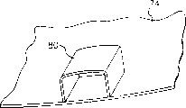
Fig. 8 is the scheme drawing of the shielding part of the intake structure of the present invention's two-wheeled engine;
Fig. 9 for the shielding part of the intake structure of the present invention's two-wheeled engine in the scheme drawing of another angle;
Figure 10 is the scheme drawing of another example of the shielding part of expression the present invention's two-wheeled engine air admittance structure; And
Figure 11 is the scheme drawing of the another example of the shielding part of expression the present invention's two-wheeled engine air admittance structure.
The specific embodiment
With reference to Fig. 3, Fig. 4 and Fig. 5, they are by block diagram, right side view and the birds-eye view of the intake structure 30 of the two-wheeled engine that is respectively expression the present invention.In fact the intake structure 30 of this two-wheeled engine is an air filtration plant, and it comprises an air inlet pipe 32, an inlet plenum 33, an exhaust chamber 34, a connection pipe 35, a partition wall 36 and a discharge port 37.The opening 31 of this air inlet pipe 32 is a lateral openings, falls in this air inlet pipe 32 because of gravity to prevent foreign material.These air inlet pipe 32 bottom approximate vertical are connected in one of this inlet plenum 33 inclined-plane 38, so that air is imported in this inlet plenum 33.This discharge port 37 is located at the bottom of this inlet plenum 33, with the moisture that condenses in the deaeration.This partition wall 36 is installed between this inlet plenum 33 and the exhaust chamber 34, as the usefulness of separating both.This connection pipe 35 is held before being connected in this exhaust chamber 34, so that the air after will filtering is sent to engine.
With reference to Fig. 6, Fig. 6 is the section-drawing along 2-2 hatching among Fig. 4.This partition wall 36 is in conjunction with an airfilter 39, and this airfilter 39 is located between this inlet plenum 33 and the exhaust chamber 34, in order to filter the air in this inlet plenum 33.The flow path of this air is for to enter this inlet plenum 33 via this air inlet pipe 32, and filters through this airfilter 39 and to transfer to this exhaust chamber 34 after forming clean air, is sent to engine via Fig. 3 to this connection pipe 35 shown in Figure 5 more at last.
Fig. 7 show will this two-wheeled engine intake structure 30 be installed in state when two-wheeled, be the view when car inside looks out, right-hand towards headstock, left then is the direction of the tailstock.For express clear for the purpose of, Fig. 7 only show two-wheeled in partial component related to the present invention.The intake structure 30 of this two-wheeled engine is fixedly arranged on this two-wheeled change speed gear box 75, and its side is connected in a Shock absorber 73.One of this connection pipe 35 end is connected to an engine 72, to provide this engine 72 required air.This opening 31 is positioned at the below of this car beam 71, and is not fixed.One shielding part 80 is fixed in this car beam 71, and can form a semi-hermetic space that this opening 31 is coated in it with a side shell 74, to avoid the intrusion of aqueous vapor and dust.In addition, this air inlet pipe 32 leans forward towards this two-wheeled headstock direction, and forms the angle of 50 to 70 degree with ground.This design of leaning forward can make the upright angle of this air inlet pipe 32 be approximately perpendicular to the center of vibration point in the two-wheeled design, and more increases integrally-built stability.
Fig. 8 and Fig. 9 are that this shielding part 80 is in the block diagram of different angles.This shielding part 80 comprises a shell 81 and two fixing rib 82, and it can be made by rubber.Side and form opening under this shell 81 near the side of this fixing rib 82, but and these fixing rib 82 bendings with around this car beam 71 that is fixed among Fig. 7.In fact, after this shielding part 80 was fixedly arranged on this car beam 71, the side that to be equivalent to these shielding part 80 Central Plains be opening was also covered by this side shell 74 among Fig. 7, and formed roughly down semi-hermetic space of an opening.
The opening 31 of the air inlet pipe 32 of present embodiment is positioned at and is coated on this shielding part 80 and side shell 74 formed semi-hermetic spaces, so with respect to the design of the admission port that protrudes from shell in the known technology, can bring into play the better aqueous vapor and the barriering effect of dust.In addition, because the opening 31 of this air inlet pipe 32 is adopted floated design, with top maintenance one interval in this semi-hermetic space, therefore, 80 tolerable relative displacemenies of this car beam 71 and shielding part are so can omit the design of flexible snake belly tube of the prior art.The size of this shielding part 80 must cooperate moving that this air inlet pipe 32 caused in two-wheeled travelling to design, to avoid both collisions.Opening 31 because of this air inlet pipe 32 does not need to fix in addition, so can simplify package program.
Figure 10 is the scheme drawing of another example of the shielding part 80 of expression the present invention's two-wheeled engine air admittance structure, represent that this shielding part 80 also can not form as the above-mentioned structure of this car beam 71 that is fixed in this fixing rib 82, and be formed as one the formation on this side shell 74.So, can form roughly down semi-hermetic space of an opening.
Figure 11 is the scheme drawing of another example of the shielding part of expression the present invention's two-wheeled engine air admittance structure, show that this shielding part 80 also can form respectively with this side shell 74 after, more above-mentioned this shielding part 80 is set firmly (as chimeric) to be installed on this side shell 74.After this shielding part 80 was fixedly arranged on this car beam 71, these shielding part 80 Central Plains were covered by this side shell 74 by the side of opening, and formed roughly down semi-hermetic space of an opening.
The present invention's technology contents and technical characterstic are as implied above, still may be based on the present invention's teaching and announcement and do all replacement and modifications that does not deviate from spirit of the present invention yet be familiar with the technical personnel of laying in the present technique field of this technology.Therefore, the present invention's protection domain should be not limited to content shown in the embodiment, and should comprise various replacement and the modifications that do not deviate from the present invention, and the application's claims are contained.
Claims (17)
- One kind two-wheeled, comprise:One seat cushion;One engine;One car beam, it is along this two-wheeled car body longitudinal extension; AndThe intake structure of one engine comprises:One shielding part, it is positioned under this car beam and the seat cushion side, and forms roughly down semi-hermetic space of an opening; AndOne air filtration plant, it comprises an air inlet pipe, and the opening of this air inlet pipe is positioned at this semi-hermetic space, and this opening keeps a sufficient distance to cooperate the vibration between this two-wheeled advancing with the top in this semi-hermetic space.
- 2. two-wheeled as claim 1 is characterized in that: also comprise a side shell that is positioned at this seat cushion below, and this shielding part comprises a lateral opening towards this side shell, this lateral opening forms this semi-hermetic space via covering of this side shell.
- 3. two-wheeled as claim 1, it is characterized in that: the opening of this air inlet pipe is towards vehicle body side.
- 4. two-wheeled as claim 1, it is characterized in that: this shielding part also comprises at least one fixing rib, in order to be fixed in this car beam.
- 5. two-wheeled as claim 1, it is characterized in that: this shielding part is made by rubber.
- 6. two-wheeled as claim 2, it is characterized in that: this shielding part is integrally formed at person on this side shell.
- 7. two-wheeled as claim 2 is characterized in that: after this shielding part and this side shell form respectively, be fixedly arranged on person on this side shell again.
- 8. two-wheeled as claim 1, it is characterized in that: this air inlet pipe leans forward towards this two-wheeled headstock direction, and forms the angle of 50 to 70 degree with ground.
- 9. two-wheeled as claim 1, it is characterized in that: this air filtration plant comprises an inlet plenum, an exhaust chamber, a partition wall and an airfilter in addition, and this inlet plenum and exhaust chamber system utilize this partition wall and airfilter to separate.
- 10. two-wheeled as claim 9, it is characterized in that: this inlet plenum comprises an inclined-plane, and this air inlet pipe approximate vertical is connected in this inclined-plane.
- 11. two-wheeled as claim 9, it is characterized in that: this air filtration plant comprises a connection pipe in addition, one of this connection pipe end be connected to this exhaust chamber with the transmission air to this engine.
- 12. two-wheeled as claim 9, it is characterized in that: this inlet plenum bottom comprises a discharge port in addition.
- 13. the intake structure of a two-wheeled engine comprises:One inlet plenum;One exhaust chamber;One connection pipe, the one end is connected in this exhaust chamber, and the other end is connected to this two-wheeled engine;One air inlet pipe, it leans forward towards the direction of this connection pipe;One partition wall, it is used to separate this inlet plenum and exhaust chamber; AndOne airfilter, it is used to filter the air of this inlet plenum and transmits it to this exhaust chamber.
- 14. the intake structure as the two-wheeled engine of claim 13 is characterized in that: also comprise a discharge port that is installed in this inlet plenum bottom.
- 15. as the intake structure of the two-wheeled engine of claim 13, it is characterized in that: this inlet plenum has the inclined-plane that leans forward, and this air inlet pipe approximate vertical is connected in this inclined-plane.
- 16. the intake structure as the two-wheeled engine of claim 13 is characterized in that: this air inlet pipe and ground form the angle of 50 to 70 degree.
- 17. as the intake structure of the two-wheeled engine of claim 13, it is characterized in that: this air inlet pipe comprises an opening towards this intake structure side.
Priority Applications (3)
| Application Number | Priority Date | Filing Date | Title |
|---|---|---|---|
| CNB031237185A CN100406339C (en) | 2003-05-20 | 2003-05-20 | Air inlet structure for motor two-wheel cycle engine and motor two-wheeled cycle with the same air in let structure of engine |
| EP04011944.8A EP1479603B1 (en) | 2003-05-20 | 2004-05-19 | Air intake structure for an engine of a motorcycle and motorcycle comprising an air intake structure |
| JP2004150418A JP2004345634A (en) | 2003-05-20 | 2004-05-20 | Motorcycle |
Applications Claiming Priority (1)
| Application Number | Priority Date | Filing Date | Title |
|---|---|---|---|
| CNB031237185A CN100406339C (en) | 2003-05-20 | 2003-05-20 | Air inlet structure for motor two-wheel cycle engine and motor two-wheeled cycle with the same air in let structure of engine |
Publications (2)
| Publication Number | Publication Date |
|---|---|
| CN1548331A true CN1548331A (en) | 2004-11-24 |
| CN100406339C CN100406339C (en) | 2008-07-30 |
Family
ID=33035153
Family Applications (1)
| Application Number | Title | Priority Date | Filing Date |
|---|---|---|---|
| CNB031237185A Expired - Fee Related CN100406339C (en) | 2003-05-20 | 2003-05-20 | Air inlet structure for motor two-wheel cycle engine and motor two-wheeled cycle with the same air in let structure of engine |
Country Status (3)
| Country | Link |
|---|---|
| EP (1) | EP1479603B1 (en) |
| JP (1) | JP2004345634A (en) |
| CN (1) | CN100406339C (en) |
Cited By (5)
| Publication number | Priority date | Publication date | Assignee | Title |
|---|---|---|---|---|
| CN100486839C (en) * | 2005-01-21 | 2009-05-13 | 艾尔英克林格股份公司 | Structural component, in particular a shield |
| CN101348143B (en) * | 2007-07-20 | 2012-04-04 | 光阳工业股份有限公司 | Motorcycle side cover structure |
| CN104350266A (en) * | 2012-06-07 | 2015-02-11 | 沃尔沃建筑设备公司 | An arrangement and a method for controlling the temperature of air being fed to a vehicle engine |
| CN110318923A (en) * | 2018-03-30 | 2019-10-11 | 本田技研工业株式会社 | Air intake structure for the internal combustion engine used on saddle vehicle |
| JP2022076820A (en) * | 2020-11-10 | 2022-05-20 | 本田技研工業株式会社 | Saddle riding vehicle |
Families Citing this family (3)
| Publication number | Priority date | Publication date | Assignee | Title |
|---|---|---|---|---|
| JP2007265461A (en) | 2006-03-27 | 2007-10-11 | Denso Corp | In-vehicle device |
| CN102305158A (en) * | 2011-08-12 | 2012-01-04 | 重庆长安汽车股份有限公司 | Air inlet system of miniature automobile engine |
| CN114294135B (en) * | 2022-01-05 | 2023-04-07 | 浙江钱江摩托股份有限公司 | Air inlet structure of motorcycle engine |
Family Cites Families (26)
| Publication number | Priority date | Publication date | Assignee | Title |
|---|---|---|---|---|
| JPS6010200Y2 (en) * | 1980-04-11 | 1985-04-08 | 本田技研工業株式会社 | Motorcycle air cleaner device |
| ES518472A0 (en) * | 1981-12-23 | 1983-12-01 | Honda Motor Co Ltd | A BELT TRANSMISSION DEVICE. |
| JPS60102423U (en) * | 1983-12-19 | 1985-07-12 | スズキ株式会社 | Motorcycle engine cooling air exhaust device |
| JPS60174323A (en) * | 1984-02-20 | 1985-09-07 | Suzuki Motor Co Ltd | Intake suction apparatus for small-sized car |
| JPS61175124A (en) * | 1985-01-29 | 1986-08-06 | Honda Motor Co Ltd | Suction device in power unit |
| JP2716720B2 (en) * | 1988-03-14 | 1998-02-18 | 本田技研工業株式会社 | Motor cleaner air cleaner chamber mounting structure |
| JP2761117B2 (en) * | 1991-03-20 | 1998-06-04 | 本田技研工業株式会社 | Air intake device for scooter type vehicle |
| JPH0565086A (en) * | 1991-09-06 | 1993-03-19 | Suzuki Motor Corp | Motor scooter engine cooling device |
| JPH06219366A (en) * | 1993-01-25 | 1994-08-09 | Suzuki Motor Corp | Air intake device for scooter type vehicle |
| JP3531953B2 (en) * | 1993-10-08 | 2004-05-31 | スズキ株式会社 | Air intake device for scooter type vehicle |
| JP3373921B2 (en) * | 1993-12-27 | 2003-02-04 | 本田技研工業株式会社 | Vaporizer warmer for motorcycles |
| JP3609121B2 (en) * | 1994-06-11 | 2005-01-12 | 本田技研工業株式会社 | Scooter air intake |
| JPH0814036A (en) * | 1994-06-28 | 1996-01-16 | Suzuki Motor Corp | Mounting structure of intake hose for second air cleaner |
| JPH0811765A (en) * | 1994-06-28 | 1996-01-16 | Suzuki Motor Corp | Fitting structure of intake hose for second air cleaner |
| JP3751077B2 (en) * | 1996-05-17 | 2006-03-01 | 本田技研工業株式会社 | Intake air intake structure for scooter type vehicles |
| JPH11171075A (en) * | 1997-12-09 | 1999-06-29 | Yamaha Motor Co Ltd | Motorcycle |
| JP4145379B2 (en) * | 1998-01-17 | 2008-09-03 | 本田技研工業株式会社 | Scooter type vehicle intake system |
| JP2000219186A (en) * | 1999-01-29 | 2000-08-08 | Honda Motor Co Ltd | Bicycle with internal combustion engine |
| JP4249345B2 (en) * | 1999-08-31 | 2009-04-02 | ヤマハ発動機株式会社 | Scooter type motorcycle air cleaner |
| JP4240431B2 (en) * | 1999-09-24 | 2009-03-18 | 本田技研工業株式会社 | Motorcycle air cleaner equipment |
| JP3974333B2 (en) * | 2001-01-19 | 2007-09-12 | 本田技研工業株式会社 | Air cleaner structure for vehicles |
| JP2003176762A (en) * | 2001-09-27 | 2003-06-27 | Yamaha Motor Co Ltd | Fuel hose mounting structure for fuel injection engine |
| JP2003127950A (en) * | 2001-10-23 | 2003-05-08 | Suzuki Motor Corp | Arrangement structure of air cleaner in motorcycle |
| JP3978335B2 (en) * | 2001-12-20 | 2007-09-19 | ヤマハ発動機株式会社 | New air intake structure of scooter type motorcycle |
| JP2004231172A (en) * | 2003-01-10 | 2004-08-19 | Yamaha Motor Co Ltd | Air cleaner device for motorcycle |
| JP4379864B2 (en) * | 2003-09-12 | 2009-12-09 | ヤマハ発動機株式会社 | Scooter type motorcycle |
-
2003
- 2003-05-20 CN CNB031237185A patent/CN100406339C/en not_active Expired - Fee Related
-
2004
- 2004-05-19 EP EP04011944.8A patent/EP1479603B1/en not_active Expired - Lifetime
- 2004-05-20 JP JP2004150418A patent/JP2004345634A/en not_active Withdrawn
Cited By (7)
| Publication number | Priority date | Publication date | Assignee | Title |
|---|---|---|---|---|
| CN100486839C (en) * | 2005-01-21 | 2009-05-13 | 艾尔英克林格股份公司 | Structural component, in particular a shield |
| CN101348143B (en) * | 2007-07-20 | 2012-04-04 | 光阳工业股份有限公司 | Motorcycle side cover structure |
| CN104350266A (en) * | 2012-06-07 | 2015-02-11 | 沃尔沃建筑设备公司 | An arrangement and a method for controlling the temperature of air being fed to a vehicle engine |
| CN110318923A (en) * | 2018-03-30 | 2019-10-11 | 本田技研工业株式会社 | Air intake structure for the internal combustion engine used on saddle vehicle |
| CN110318923B (en) * | 2018-03-30 | 2021-12-28 | 本田技研工业株式会社 | Intake structure for internal combustion engine used on saddle type vehicle |
| JP2022076820A (en) * | 2020-11-10 | 2022-05-20 | 本田技研工業株式会社 | Saddle riding vehicle |
| JP7309681B2 (en) | 2020-11-10 | 2023-07-18 | 本田技研工業株式会社 | saddle-riding vehicle |
Also Published As
| Publication number | Publication date |
|---|---|
| EP1479603A3 (en) | 2008-05-21 |
| CN100406339C (en) | 2008-07-30 |
| JP2004345634A (en) | 2004-12-09 |
| EP1479603B1 (en) | 2019-07-03 |
| EP1479603A2 (en) | 2004-11-24 |
Similar Documents
| Publication | Publication Date | Title |
|---|---|---|
| KR100558421B1 (en) | Intake device of engine for vehicle | |
| CN101683873B (en) | Motorcycle | |
| CN103161622A (en) | Intake system of vehicle engine installed in engine compartment | |
| CN101468698A (en) | Vehicle with structure for improved engine output | |
| CN1548331A (en) | Air inlet structure for motor two-wheel cycle engine and motor two-wheeled cycle with the same air in let structure of engine | |
| CN101172504B (en) | Automotive tumbrel | |
| CN101172503A (en) | Automotive tumbrel | |
| CN101946078A (en) | The heat radiating fin structure that is used for on-vehicle internal combustion engine | |
| CN103097235A (en) | Structural arrangement for battery for saddle-ridden vehicle | |
| CN1184100C (en) | Air intake structure of two-wheeled motor vehicle | |
| CN1366129A (en) | Structure of air filter for vehicle | |
| CN102207048A (en) | Air inlet pipe of water separation air filter | |
| CN101172505B (en) | Automotive tumbrel | |
| CN1304750C (en) | Air cleaner structure of motorcycle | |
| CN104141566B (en) | The air cleaner unit of pedal type vehicle | |
| JP2009067144A (en) | Maintenance vehicle | |
| CN1080222C (en) | Intake device for small motorcycle | |
| CN102785729A (en) | Saddle type vehicle | |
| CN103184957B (en) | Air cleaner apparatus and straddle-type vehicle equipped with the apparatus | |
| CN1167571C (en) | Cover structure of motorcycle | |
| CN1517263A (en) | Two-wheel motorcycle and its air inlet purification device | |
| JP4395025B2 (en) | Intake device for vehicle engine | |
| CN203856550U (en) | Water sprinkling motor vehicle tail gas purifier | |
| CN104010931A (en) | Straddled vehicle | |
| CN107796033A (en) | A kind of smoke exhaust ventilator for preventing blower interior from polluting |
Legal Events
| Date | Code | Title | Description |
|---|---|---|---|
| C06 | Publication | ||
| PB01 | Publication | ||
| C10 | Entry into substantive examination | ||
| SE01 | Entry into force of request for substantive examination | ||
| C14 | Grant of patent or utility model | ||
| GR01 | Patent grant | ||
| CF01 | Termination of patent right due to non-payment of annual fee |
Granted publication date: 20080730 |
|
| CF01 | Termination of patent right due to non-payment of annual fee |