CN1495683A - Depositing layers in OLED devices using viscous flow - Google Patents
Depositing layers in OLED devices using viscous flow Download PDFInfo
- Publication number
- CN1495683A CN1495683A CNA031327494A CN03132749A CN1495683A CN 1495683 A CN1495683 A CN 1495683A CN A031327494 A CNA031327494 A CN A031327494A CN 03132749 A CN03132749 A CN 03132749A CN 1495683 A CN1495683 A CN 1495683A
- Authority
- CN
- China
- Prior art keywords
- manifold
- substrate
- organic
- oled display
- inert gas
- Prior art date
- Legal status (The legal status is an assumption and is not a legal conclusion. Google has not performed a legal analysis and makes no representation as to the accuracy of the status listed.)
- Pending
Links
- 238000000151 deposition Methods 0.000 title claims abstract description 36
- 239000000758 substrate Substances 0.000 claims abstract description 192
- 239000011261 inert gas Substances 0.000 claims abstract description 109
- 238000000034 method Methods 0.000 claims abstract description 92
- 239000007789 gas Substances 0.000 claims abstract description 85
- 239000000463 material Substances 0.000 claims abstract description 85
- 239000011368 organic material Substances 0.000 claims abstract description 78
- 239000012044 organic layer Substances 0.000 claims abstract description 37
- 239000010410 layer Substances 0.000 claims description 116
- 239000002019 doping agent Substances 0.000 claims description 50
- 239000011159 matrix material Substances 0.000 claims description 38
- 229910052751 metal Inorganic materials 0.000 claims description 18
- 239000002184 metal Substances 0.000 claims description 18
- 230000033001 locomotion Effects 0.000 claims description 13
- 239000011521 glass Substances 0.000 claims description 7
- 230000008569 process Effects 0.000 claims description 6
- 150000002739 metals Chemical class 0.000 claims description 4
- VYPSYNLAJGMNEJ-UHFFFAOYSA-N silicon dioxide Inorganic materials O=[Si]=O VYPSYNLAJGMNEJ-UHFFFAOYSA-N 0.000 claims description 4
- 239000000919 ceramic Substances 0.000 claims description 3
- 230000008016 vaporization Effects 0.000 claims description 3
- OKTJSMMVPCPJKN-UHFFFAOYSA-N Carbon Chemical compound [C] OKTJSMMVPCPJKN-UHFFFAOYSA-N 0.000 claims description 2
- 239000010439 graphite Substances 0.000 claims description 2
- 229910002804 graphite Inorganic materials 0.000 claims description 2
- 239000010453 quartz Substances 0.000 claims description 2
- ZUOUZKKEUPVFJK-UHFFFAOYSA-N diphenyl Chemical group C1=CC=CC=C1C1=CC=CC=C1 ZUOUZKKEUPVFJK-UHFFFAOYSA-N 0.000 description 27
- 238000005401 electroluminescence Methods 0.000 description 24
- 238000002347 injection Methods 0.000 description 20
- 239000007924 injection Substances 0.000 description 20
- 230000001276 controlling effect Effects 0.000 description 19
- 230000032258 transport Effects 0.000 description 18
- 238000007740 vapor deposition Methods 0.000 description 18
- 230000005525 hole transport Effects 0.000 description 17
- -1 zinc selenide Chemical class 0.000 description 17
- 125000003118 aryl group Chemical group 0.000 description 16
- 230000008021 deposition Effects 0.000 description 16
- 238000010438 heat treatment Methods 0.000 description 16
- 238000004519 manufacturing process Methods 0.000 description 15
- 239000004305 biphenyl Chemical group 0.000 description 14
- 235000010290 biphenyl Nutrition 0.000 description 14
- 239000010409 thin film Substances 0.000 description 12
- 239000003086 colorant Substances 0.000 description 11
- 125000004432 carbon atom Chemical group C* 0.000 description 10
- 238000009833 condensation Methods 0.000 description 10
- 230000005494 condensation Effects 0.000 description 10
- 150000001875 compounds Chemical class 0.000 description 9
- 229910052757 nitrogen Inorganic materials 0.000 description 9
- MCJGNVYPOGVAJF-UHFFFAOYSA-N quinolin-8-ol Chemical compound C1=CN=C2C(O)=CC=CC2=C1 MCJGNVYPOGVAJF-UHFFFAOYSA-N 0.000 description 9
- 125000005259 triarylamine group Chemical group 0.000 description 8
- 125000000217 alkyl group Chemical group 0.000 description 7
- 229960003540 oxyquinoline Drugs 0.000 description 7
- 229920001621 AMOLED Polymers 0.000 description 6
- UFWIBTONFRDIAS-UHFFFAOYSA-N Naphthalene Chemical compound C1=CC=CC2=CC=CC=C21 UFWIBTONFRDIAS-UHFFFAOYSA-N 0.000 description 6
- 125000000732 arylene group Chemical group 0.000 description 6
- 238000000859 sublimation Methods 0.000 description 6
- 230000008022 sublimation Effects 0.000 description 6
- 239000011364 vaporized material Substances 0.000 description 6
- 229910052782 aluminium Inorganic materials 0.000 description 5
- XAGFODPZIPBFFR-UHFFFAOYSA-N aluminium Chemical compound [Al] XAGFODPZIPBFFR-UHFFFAOYSA-N 0.000 description 5
- 125000004429 atom Chemical group 0.000 description 5
- 239000010406 cathode material Substances 0.000 description 5
- 238000010586 diagram Methods 0.000 description 5
- XKRFYHLGVUSROY-UHFFFAOYSA-N Argon Chemical compound [Ar] XKRFYHLGVUSROY-UHFFFAOYSA-N 0.000 description 4
- IJGRMHOSHXDMSA-UHFFFAOYSA-N Atomic nitrogen Chemical compound N#N IJGRMHOSHXDMSA-UHFFFAOYSA-N 0.000 description 4
- 239000007983 Tris buffer Substances 0.000 description 4
- XLOMVQKBTHCTTD-UHFFFAOYSA-N Zinc monoxide Chemical compound [Zn]=O XLOMVQKBTHCTTD-UHFFFAOYSA-N 0.000 description 4
- QVGXLLKOCUKJST-UHFFFAOYSA-N atomic oxygen Chemical compound [O] QVGXLLKOCUKJST-UHFFFAOYSA-N 0.000 description 4
- 230000008878 coupling Effects 0.000 description 4
- 238000010168 coupling process Methods 0.000 description 4
- 238000005859 coupling reaction Methods 0.000 description 4
- 238000009826 distribution Methods 0.000 description 4
- 230000000694 effects Effects 0.000 description 4
- 238000005516 engineering process Methods 0.000 description 4
- 125000001072 heteroaryl group Chemical group 0.000 description 4
- 239000001257 hydrogen Substances 0.000 description 4
- 229910052739 hydrogen Inorganic materials 0.000 description 4
- AMGQUBHHOARCQH-UHFFFAOYSA-N indium;oxotin Chemical compound [In].[Sn]=O AMGQUBHHOARCQH-UHFFFAOYSA-N 0.000 description 4
- 238000007641 inkjet printing Methods 0.000 description 4
- 230000003287 optical effect Effects 0.000 description 4
- 239000001301 oxygen Substances 0.000 description 4
- 229910052760 oxygen Inorganic materials 0.000 description 4
- 238000000059 patterning Methods 0.000 description 4
- 238000005240 physical vapour deposition Methods 0.000 description 4
- 238000007789 sealing Methods 0.000 description 4
- 101001109993 Artemia salina 60S acidic ribosomal protein P2 Proteins 0.000 description 3
- ZAMOUSCENKQFHK-UHFFFAOYSA-N Chlorine atom Chemical compound [Cl] ZAMOUSCENKQFHK-UHFFFAOYSA-N 0.000 description 3
- PXGOKWXKJXAPGV-UHFFFAOYSA-N Fluorine Chemical compound FF PXGOKWXKJXAPGV-UHFFFAOYSA-N 0.000 description 3
- GYHNNYVSQQEPJS-UHFFFAOYSA-N Gallium Chemical compound [Ga] GYHNNYVSQQEPJS-UHFFFAOYSA-N 0.000 description 3
- 230000009471 action Effects 0.000 description 3
- 230000002411 adverse Effects 0.000 description 3
- 239000003570 air Substances 0.000 description 3
- 125000002947 alkylene group Chemical group 0.000 description 3
- REDXJYDRNCIFBQ-UHFFFAOYSA-N aluminium(3+) Chemical compound [Al+3] REDXJYDRNCIFBQ-UHFFFAOYSA-N 0.000 description 3
- 239000010405 anode material Substances 0.000 description 3
- 238000013459 approach Methods 0.000 description 3
- 229910052799 carbon Inorganic materials 0.000 description 3
- 238000005229 chemical vapour deposition Methods 0.000 description 3
- 239000000460 chlorine Substances 0.000 description 3
- 229910052801 chlorine Inorganic materials 0.000 description 3
- 239000004020 conductor Substances 0.000 description 3
- 125000000753 cycloalkyl group Chemical group 0.000 description 3
- 238000009792 diffusion process Methods 0.000 description 3
- 239000006185 dispersion Substances 0.000 description 3
- 238000005538 encapsulation Methods 0.000 description 3
- 238000010304 firing Methods 0.000 description 3
- 229910052731 fluorine Inorganic materials 0.000 description 3
- 239000011737 fluorine Substances 0.000 description 3
- 229910052733 gallium Inorganic materials 0.000 description 3
- 125000000623 heterocyclic group Chemical group 0.000 description 3
- 125000004435 hydrogen atom Chemical class [H]* 0.000 description 3
- 150000002475 indoles Chemical class 0.000 description 3
- 238000011068 loading method Methods 0.000 description 3
- 239000000203 mixture Substances 0.000 description 3
- 150000004880 oxines Chemical class 0.000 description 3
- 125000001997 phenyl group Chemical group [H]C1=C([H])C([H])=C(*)C([H])=C1[H] 0.000 description 3
- 239000011295 pitch Substances 0.000 description 3
- 125000003367 polycyclic group Chemical group 0.000 description 3
- 229920000642 polymer Polymers 0.000 description 3
- 125000002924 primary amino group Chemical group [H]N([H])* 0.000 description 3
- 125000001424 substituent group Chemical group 0.000 description 3
- LQRAULANJCQXAM-UHFFFAOYSA-N 1-n,5-n-dinaphthalen-1-yl-1-n,5-n-diphenylnaphthalene-1,5-diamine Chemical compound C1=CC=CC=C1N(C=1C2=CC=CC(=C2C=CC=1)N(C=1C=CC=CC=1)C=1C2=CC=CC=C2C=CC=1)C1=CC=CC2=CC=CC=C12 LQRAULANJCQXAM-UHFFFAOYSA-N 0.000 description 2
- NBYLBWHHTUWMER-UHFFFAOYSA-N 2-Methylquinolin-8-ol Chemical compound C1=CC=C(O)C2=NC(C)=CC=C21 NBYLBWHHTUWMER-UHFFFAOYSA-N 0.000 description 2
- 239000005725 8-Hydroxyquinoline Substances 0.000 description 2
- VIZUPBYFLORCRA-UHFFFAOYSA-N 9,10-dinaphthalen-2-ylanthracene Chemical class C12=CC=CC=C2C(C2=CC3=CC=CC=C3C=C2)=C(C=CC=C2)C2=C1C1=CC=C(C=CC=C2)C2=C1 VIZUPBYFLORCRA-UHFFFAOYSA-N 0.000 description 2
- WKBOTKDWSSQWDR-UHFFFAOYSA-N Bromine atom Chemical compound [Br] WKBOTKDWSSQWDR-UHFFFAOYSA-N 0.000 description 2
- WHXSMMKQMYFTQS-UHFFFAOYSA-N Lithium Chemical compound [Li] WHXSMMKQMYFTQS-UHFFFAOYSA-N 0.000 description 2
- KDLHZDBZIXYQEI-UHFFFAOYSA-N Palladium Chemical compound [Pd] KDLHZDBZIXYQEI-UHFFFAOYSA-N 0.000 description 2
- QCWXUUIWCKQGHC-UHFFFAOYSA-N Zirconium Chemical compound [Zr] QCWXUUIWCKQGHC-UHFFFAOYSA-N 0.000 description 2
- 238000005299 abrasion Methods 0.000 description 2
- 125000003342 alkenyl group Chemical group 0.000 description 2
- MWPLVEDNUUSJAV-UHFFFAOYSA-N anthracene Chemical compound C1=CC=CC2=CC3=CC=CC=C3C=C21 MWPLVEDNUUSJAV-UHFFFAOYSA-N 0.000 description 2
- 229910052786 argon Inorganic materials 0.000 description 2
- 230000005540 biological transmission Effects 0.000 description 2
- GDTBXPJZTBHREO-UHFFFAOYSA-N bromine Substances BrBr GDTBXPJZTBHREO-UHFFFAOYSA-N 0.000 description 2
- 229910052794 bromium Inorganic materials 0.000 description 2
- OSGAYBCDTDRGGQ-UHFFFAOYSA-L calcium sulfate Chemical compound [Ca+2].[O-]S([O-])(=O)=O OSGAYBCDTDRGGQ-UHFFFAOYSA-L 0.000 description 2
- 239000003990 capacitor Substances 0.000 description 2
- 150000001721 carbon Chemical group 0.000 description 2
- 238000004140 cleaning Methods 0.000 description 2
- 239000011248 coating agent Substances 0.000 description 2
- 238000000576 coating method Methods 0.000 description 2
- 230000005574 cross-species transmission Effects 0.000 description 2
- 230000007547 defect Effects 0.000 description 2
- 238000001704 evaporation Methods 0.000 description 2
- 230000008020 evaporation Effects 0.000 description 2
- NIHNNTQXNPWCJQ-UHFFFAOYSA-N fluorene Chemical compound C1=CC=C2CC3=CC=CC=C3C2=C1 NIHNNTQXNPWCJQ-UHFFFAOYSA-N 0.000 description 2
- 230000006870 function Effects 0.000 description 2
- 125000002541 furyl group Chemical group 0.000 description 2
- 238000003384 imaging method Methods 0.000 description 2
- 229910052738 indium Inorganic materials 0.000 description 2
- APFVFJFRJDLVQX-UHFFFAOYSA-N indium atom Chemical compound [In] APFVFJFRJDLVQX-UHFFFAOYSA-N 0.000 description 2
- 239000007788 liquid Substances 0.000 description 2
- 229910052744 lithium Inorganic materials 0.000 description 2
- 239000011777 magnesium Substances 0.000 description 2
- 125000001624 naphthyl group Chemical group 0.000 description 2
- 125000000843 phenylene group Chemical group C1(=C(C=CC=C1)*)* 0.000 description 2
- 229920003023 plastic Polymers 0.000 description 2
- 239000004033 plastic Substances 0.000 description 2
- BASFCYQUMIYNBI-UHFFFAOYSA-N platinum Chemical compound [Pt] BASFCYQUMIYNBI-UHFFFAOYSA-N 0.000 description 2
- 229920003227 poly(N-vinyl carbazole) Polymers 0.000 description 2
- 239000000843 powder Substances 0.000 description 2
- 125000004076 pyridyl group Chemical group 0.000 description 2
- 125000002943 quinolinyl group Chemical group N1=C(C=CC2=CC=CC=C12)* 0.000 description 2
- 230000005855 radiation Effects 0.000 description 2
- 230000006798 recombination Effects 0.000 description 2
- 238000005215 recombination Methods 0.000 description 2
- 238000004544 sputter deposition Methods 0.000 description 2
- 238000003860 storage Methods 0.000 description 2
- 125000003107 substituted aryl group Chemical group 0.000 description 2
- 125000001544 thienyl group Chemical group 0.000 description 2
- 229910052723 transition metal Inorganic materials 0.000 description 2
- 150000003624 transition metals Chemical class 0.000 description 2
- 238000009834 vaporization Methods 0.000 description 2
- 229920002554 vinyl polymer Polymers 0.000 description 2
- 239000011787 zinc oxide Substances 0.000 description 2
- 229910052726 zirconium Inorganic materials 0.000 description 2
- PFNQVRZLDWYSCW-UHFFFAOYSA-N (fluoren-9-ylideneamino) n-naphthalen-1-ylcarbamate Chemical compound C12=CC=CC=C2C2=CC=CC=C2C1=NOC(=O)NC1=CC=CC2=CC=CC=C12 PFNQVRZLDWYSCW-UHFFFAOYSA-N 0.000 description 1
- XNCMQRWVMWLODV-UHFFFAOYSA-N 1-phenylbenzimidazole Chemical compound C1=NC2=CC=CC=C2N1C1=CC=CC=C1 XNCMQRWVMWLODV-UHFFFAOYSA-N 0.000 description 1
- MVLOINQUZSPUJS-UHFFFAOYSA-N 2-n,2-n,6-n,6-n-tetrakis(4-methylphenyl)naphthalene-2,6-diamine Chemical compound C1=CC(C)=CC=C1N(C=1C=C2C=CC(=CC2=CC=1)N(C=1C=CC(C)=CC=1)C=1C=CC(C)=CC=1)C1=CC=C(C)C=C1 MVLOINQUZSPUJS-UHFFFAOYSA-N 0.000 description 1
- MATLFWDVOBGZFG-UHFFFAOYSA-N 2-n,2-n,6-n,6-n-tetranaphthalen-1-ylnaphthalene-2,6-diamine Chemical compound C1=CC=C2C(N(C=3C=C4C=CC(=CC4=CC=3)N(C=3C4=CC=CC=C4C=CC=3)C=3C4=CC=CC=C4C=CC=3)C=3C4=CC=CC=C4C=CC=3)=CC=CC2=C1 MATLFWDVOBGZFG-UHFFFAOYSA-N 0.000 description 1
- VXJRNCUNIBHMKV-UHFFFAOYSA-N 2-n,6-n-dinaphthalen-1-yl-2-n,6-n-dinaphthalen-2-ylnaphthalene-2,6-diamine Chemical compound C1=CC=C2C(N(C=3C=C4C=CC(=CC4=CC=3)N(C=3C=C4C=CC=CC4=CC=3)C=3C4=CC=CC=C4C=CC=3)C3=CC4=CC=CC=C4C=C3)=CC=CC2=C1 VXJRNCUNIBHMKV-UHFFFAOYSA-N 0.000 description 1
- KYGSXEYUWRFVNY-UHFFFAOYSA-N 2-pyran-2-ylidenepropanedinitrile Chemical compound N#CC(C#N)=C1OC=CC=C1 KYGSXEYUWRFVNY-UHFFFAOYSA-N 0.000 description 1
- OBAJPWYDYFEBTF-UHFFFAOYSA-N 2-tert-butyl-9,10-dinaphthalen-2-ylanthracene Chemical compound C1=CC=CC2=CC(C3=C4C=CC=CC4=C(C=4C=C5C=CC=CC5=CC=4)C4=CC=C(C=C43)C(C)(C)C)=CC=C21 OBAJPWYDYFEBTF-UHFFFAOYSA-N 0.000 description 1
- GOLORTLGFDVFDW-UHFFFAOYSA-N 3-(1h-benzimidazol-2-yl)-7-(diethylamino)chromen-2-one Chemical compound C1=CC=C2NC(C3=CC4=CC=C(C=C4OC3=O)N(CC)CC)=NC2=C1 GOLORTLGFDVFDW-UHFFFAOYSA-N 0.000 description 1
- AHDTYXOIJHCGKH-UHFFFAOYSA-N 4-[[4-(dimethylamino)-2-methylphenyl]-phenylmethyl]-n,n,3-trimethylaniline Chemical compound CC1=CC(N(C)C)=CC=C1C(C=1C(=CC(=CC=1)N(C)C)C)C1=CC=CC=C1 AHDTYXOIJHCGKH-UHFFFAOYSA-N 0.000 description 1
- MAGFQRLKWCCTQJ-UHFFFAOYSA-M 4-ethenylbenzenesulfonate Chemical compound [O-]S(=O)(=O)C1=CC=C(C=C)C=C1 MAGFQRLKWCCTQJ-UHFFFAOYSA-M 0.000 description 1
- YXYUIABODWXVIK-UHFFFAOYSA-N 4-methyl-n,n-bis(4-methylphenyl)aniline Chemical compound C1=CC(C)=CC=C1N(C=1C=CC(C)=CC=1)C1=CC=C(C)C=C1 YXYUIABODWXVIK-UHFFFAOYSA-N 0.000 description 1
- MEIBOBDKQKIBJH-UHFFFAOYSA-N 4-methyl-n-[4-[1-[4-(4-methyl-n-(4-methylphenyl)anilino)phenyl]-4-phenylcyclohexyl]phenyl]-n-(4-methylphenyl)aniline Chemical compound C1=CC(C)=CC=C1N(C=1C=CC(=CC=1)C1(CCC(CC1)C=1C=CC=CC=1)C=1C=CC(=CC=1)N(C=1C=CC(C)=CC=1)C=1C=CC(C)=CC=1)C1=CC=C(C)C=C1 MEIBOBDKQKIBJH-UHFFFAOYSA-N 0.000 description 1
- ZOKIJILZFXPFTO-UHFFFAOYSA-N 4-methyl-n-[4-[1-[4-(4-methyl-n-(4-methylphenyl)anilino)phenyl]cyclohexyl]phenyl]-n-(4-methylphenyl)aniline Chemical compound C1=CC(C)=CC=C1N(C=1C=CC(=CC=1)C1(CCCCC1)C=1C=CC(=CC=1)N(C=1C=CC(C)=CC=1)C=1C=CC(C)=CC=1)C1=CC=C(C)C=C1 ZOKIJILZFXPFTO-UHFFFAOYSA-N 0.000 description 1
- QCRMNYVCABKJCM-UHFFFAOYSA-N 5-methyl-2h-pyran Chemical compound CC1=COCC=C1 QCRMNYVCABKJCM-UHFFFAOYSA-N 0.000 description 1
- VIJYEGDOKCKUOL-UHFFFAOYSA-N 9-phenylcarbazole Chemical compound C1=CC=CC=C1N1C2=CC=CC=C2C2=CC=CC=C21 VIJYEGDOKCKUOL-UHFFFAOYSA-N 0.000 description 1
- GJCOSYZMQJWQCA-UHFFFAOYSA-N 9H-xanthene Chemical compound C1=CC=C2CC3=CC=CC=C3OC2=C1 GJCOSYZMQJWQCA-UHFFFAOYSA-N 0.000 description 1
- 229910001316 Ag alloy Inorganic materials 0.000 description 1
- 241000283725 Bos Species 0.000 description 1
- KAKZBPTYRLMSJV-UHFFFAOYSA-N Butadiene Chemical class C=CC=C KAKZBPTYRLMSJV-UHFFFAOYSA-N 0.000 description 1
- OYPRJOBELJOOCE-UHFFFAOYSA-N Calcium Chemical compound [Ca] OYPRJOBELJOOCE-UHFFFAOYSA-N 0.000 description 1
- RYGMFSIKBFXOCR-UHFFFAOYSA-N Copper Chemical compound [Cu] RYGMFSIKBFXOCR-UHFFFAOYSA-N 0.000 description 1
- 229910002601 GaN Inorganic materials 0.000 description 1
- JMASRVWKEDWRBT-UHFFFAOYSA-N Gallium nitride Chemical compound [Ga]#N JMASRVWKEDWRBT-UHFFFAOYSA-N 0.000 description 1
- UFHFLCQGNIYNRP-UHFFFAOYSA-N Hydrogen Chemical compound [H][H] UFHFLCQGNIYNRP-UHFFFAOYSA-N 0.000 description 1
- DGAQECJNVWCQMB-PUAWFVPOSA-M Ilexoside XXIX Chemical compound C[C@@H]1CC[C@@]2(CC[C@@]3(C(=CC[C@H]4[C@]3(CC[C@@H]5[C@@]4(CC[C@@H](C5(C)C)OS(=O)(=O)[O-])C)C)[C@@H]2[C@]1(C)O)C)C(=O)O[C@H]6[C@@H]([C@H]([C@@H]([C@H](O6)CO)O)O)O.[Na+] DGAQECJNVWCQMB-PUAWFVPOSA-M 0.000 description 1
- FYYHWMGAXLPEAU-UHFFFAOYSA-N Magnesium Chemical compound [Mg] FYYHWMGAXLPEAU-UHFFFAOYSA-N 0.000 description 1
- JLVVSXFLKOJNIY-UHFFFAOYSA-N Magnesium ion Chemical compound [Mg+2] JLVVSXFLKOJNIY-UHFFFAOYSA-N 0.000 description 1
- ZOKXTWBITQBERF-UHFFFAOYSA-N Molybdenum Chemical compound [Mo] ZOKXTWBITQBERF-UHFFFAOYSA-N 0.000 description 1
- SVFYFTJQYSXRHB-UHFFFAOYSA-N N-[4-[2-[4-(N-naphthalen-1-ylanilino)phenyl]phenyl]phenyl]-N-phenylnaphthalen-1-amine Chemical group c1ccc(cc1)N(c1ccc(cc1)-c1ccccc1-c1ccc(cc1)N(c1ccccc1)c1cccc2ccccc12)c1cccc2ccccc12 SVFYFTJQYSXRHB-UHFFFAOYSA-N 0.000 description 1
- WSIVASCVOUXVGN-UHFFFAOYSA-N O1C=COC=C1.[Mg] Chemical compound O1C=COC=C1.[Mg] WSIVASCVOUXVGN-UHFFFAOYSA-N 0.000 description 1
- GEIAQOFPUVMAGM-UHFFFAOYSA-N Oxozirconium Chemical compound [Zr]=O GEIAQOFPUVMAGM-UHFFFAOYSA-N 0.000 description 1
- 229920001609 Poly(3,4-ethylenedioxythiophene) Polymers 0.000 description 1
- ZLMJMSJWJFRBEC-UHFFFAOYSA-N Potassium Chemical compound [K] ZLMJMSJWJFRBEC-UHFFFAOYSA-N 0.000 description 1
- NRCMAYZCPIVABH-UHFFFAOYSA-N Quinacridone Chemical compound N1C2=CC=CC=C2C(=O)C2=C1C=C1C(=O)C3=CC=CC=C3NC1=C2 NRCMAYZCPIVABH-UHFFFAOYSA-N 0.000 description 1
- 239000004809 Teflon Substances 0.000 description 1
- 229920006362 Teflon® Polymers 0.000 description 1
- XBDYBAVJXHJMNQ-UHFFFAOYSA-N Tetrahydroanthracene Natural products C1=CC=C2C=C(CCCC3)C3=CC2=C1 XBDYBAVJXHJMNQ-UHFFFAOYSA-N 0.000 description 1
- 229910021536 Zeolite Inorganic materials 0.000 description 1
- HCHKCACWOHOZIP-UHFFFAOYSA-N Zinc Chemical compound [Zn] HCHKCACWOHOZIP-UHFFFAOYSA-N 0.000 description 1
- PTFCDOFLOPIGGS-UHFFFAOYSA-N Zinc dication Chemical compound [Zn+2] PTFCDOFLOPIGGS-UHFFFAOYSA-N 0.000 description 1
- 239000005083 Zinc sulfide Substances 0.000 description 1
- GENZLHCFIPDZNJ-UHFFFAOYSA-N [In+3].[O-2].[Mg+2] Chemical compound [In+3].[O-2].[Mg+2] GENZLHCFIPDZNJ-UHFFFAOYSA-N 0.000 description 1
- 229910052783 alkali metal Inorganic materials 0.000 description 1
- 229910000272 alkali metal oxide Inorganic materials 0.000 description 1
- 150000001340 alkali metals Chemical class 0.000 description 1
- 229910052784 alkaline earth metal Inorganic materials 0.000 description 1
- 229910000287 alkaline earth metal oxide Inorganic materials 0.000 description 1
- 150000001342 alkaline earth metals Chemical class 0.000 description 1
- 125000003545 alkoxy group Chemical group 0.000 description 1
- 125000000033 alkoxyamino group Chemical group 0.000 description 1
- 125000003282 alkyl amino group Chemical group 0.000 description 1
- 229910045601 alloy Inorganic materials 0.000 description 1
- 239000000956 alloy Substances 0.000 description 1
- PNEYBMLMFCGWSK-UHFFFAOYSA-N aluminium oxide Inorganic materials [O-2].[O-2].[O-2].[Al+3].[Al+3] PNEYBMLMFCGWSK-UHFFFAOYSA-N 0.000 description 1
- 239000012080 ambient air Substances 0.000 description 1
- 125000003277 amino group Chemical group 0.000 description 1
- 125000005577 anthracene group Chemical group 0.000 description 1
- 150000001454 anthracenes Chemical class 0.000 description 1
- 125000002178 anthracenyl group Chemical group C1(=CC=CC2=CC3=CC=CC=C3C=C12)* 0.000 description 1
- 229940054051 antipsychotic indole derivative Drugs 0.000 description 1
- 150000004982 aromatic amines Chemical class 0.000 description 1
- 125000001769 aryl amino group Chemical group 0.000 description 1
- 125000004104 aryloxy group Chemical group 0.000 description 1
- 230000004888 barrier function Effects 0.000 description 1
- 229910001570 bauxite Inorganic materials 0.000 description 1
- SIKJAQJRHWYJAI-UHFFFAOYSA-N benzopyrrole Natural products C1=CC=C2NC=CC2=C1 SIKJAQJRHWYJAI-UHFFFAOYSA-N 0.000 description 1
- 230000015572 biosynthetic process Effects 0.000 description 1
- 229910052791 calcium Inorganic materials 0.000 description 1
- 239000011575 calcium Substances 0.000 description 1
- 239000002775 capsule Substances 0.000 description 1
- 239000011203 carbon fibre reinforced carbon Substances 0.000 description 1
- 239000004927 clay Substances 0.000 description 1
- 229910052570 clay Inorganic materials 0.000 description 1
- 238000010276 construction Methods 0.000 description 1
- 238000001816 cooling Methods 0.000 description 1
- 229920001577 copolymer Polymers 0.000 description 1
- 238000007334 copolymerization reaction Methods 0.000 description 1
- 229910052802 copper Inorganic materials 0.000 description 1
- 239000010949 copper Substances 0.000 description 1
- 125000004093 cyano group Chemical group *C#N 0.000 description 1
- 125000002993 cycloalkylene group Chemical group 0.000 description 1
- 125000000582 cycloheptyl group Chemical group [H]C1([H])C([H])([H])C([H])([H])C([H])([H])C([H])(*)C([H])([H])C1([H])[H] 0.000 description 1
- 125000000113 cyclohexyl group Chemical group [H]C1([H])C([H])([H])C([H])([H])C([H])(*)C([H])([H])C1([H])[H] 0.000 description 1
- 125000001511 cyclopentyl group Chemical group [H]C1([H])C([H])([H])C([H])([H])C([H])(*)C1([H])[H] 0.000 description 1
- 230000006837 decompression Effects 0.000 description 1
- 230000007812 deficiency Effects 0.000 description 1
- 239000002274 desiccant Substances 0.000 description 1
- 238000001514 detection method Methods 0.000 description 1
- 125000005266 diarylamine group Chemical group 0.000 description 1
- 125000004986 diarylamino group Chemical group 0.000 description 1
- BKMIWBZIQAAZBD-UHFFFAOYSA-N diindenoperylene Chemical class C12=C3C4=CC=C2C2=CC=CC=C2C1=CC=C3C1=CC=C2C3=CC=CC=C3C3=CC=C4C1=C32 BKMIWBZIQAAZBD-UHFFFAOYSA-N 0.000 description 1
- HNPSIPDUKPIQMN-UHFFFAOYSA-N dioxosilane;oxo(oxoalumanyloxy)alumane Chemical compound O=[Si]=O.O=[Al]O[Al]=O HNPSIPDUKPIQMN-UHFFFAOYSA-N 0.000 description 1
- 238000006073 displacement reaction Methods 0.000 description 1
- 238000001035 drying Methods 0.000 description 1
- 239000000975 dye Substances 0.000 description 1
- 238000010292 electrical insulation Methods 0.000 description 1
- 239000012777 electrically insulating material Substances 0.000 description 1
- 238000011049 filling Methods 0.000 description 1
- 239000010408 film Substances 0.000 description 1
- 125000003983 fluorenyl group Chemical class C1(=CC=CC=2C3=CC=CC=C3CC12)* 0.000 description 1
- 239000007850 fluorescent dye Substances 0.000 description 1
- 229920002313 fluoropolymer Polymers 0.000 description 1
- PCHJSUWPFVWCPO-UHFFFAOYSA-N gold Chemical compound [Au] PCHJSUWPFVWCPO-UHFFFAOYSA-N 0.000 description 1
- 229910052737 gold Inorganic materials 0.000 description 1
- 239000010931 gold Substances 0.000 description 1
- 229910052736 halogen Inorganic materials 0.000 description 1
- 125000005843 halogen group Chemical group 0.000 description 1
- 150000002367 halogens Chemical class 0.000 description 1
- 125000003187 heptyl group Chemical group [H]C([*])([H])C([H])([H])C([H])([H])C([H])([H])C([H])([H])C([H])([H])C([H])([H])[H] 0.000 description 1
- 238000004770 highest occupied molecular orbital Methods 0.000 description 1
- PZOUSPYUWWUPPK-UHFFFAOYSA-N indole Natural products CC1=CC=CC2=C1C=CN2 PZOUSPYUWWUPPK-UHFFFAOYSA-N 0.000 description 1
- RKJUIXBNRJVNHR-UHFFFAOYSA-N indolenine Natural products C1=CC=C2CC=NC2=C1 RKJUIXBNRJVNHR-UHFFFAOYSA-N 0.000 description 1
- 125000001041 indolyl group Chemical group 0.000 description 1
- 230000009878 intermolecular interaction Effects 0.000 description 1
- 229910052741 iridium Inorganic materials 0.000 description 1
- GKOZUEZYRPOHIO-UHFFFAOYSA-N iridium atom Chemical compound [Ir] GKOZUEZYRPOHIO-UHFFFAOYSA-N 0.000 description 1
- 238000001540 jet deposition Methods 0.000 description 1
- 238000003698 laser cutting Methods 0.000 description 1
- QDLAGTHXVHQKRE-UHFFFAOYSA-N lichenxanthone Natural products COC1=CC(O)=C2C(=O)C3=C(C)C=C(OC)C=C3OC2=C1 QDLAGTHXVHQKRE-UHFFFAOYSA-N 0.000 description 1
- 125000005647 linker group Chemical group 0.000 description 1
- 238000004768 lowest unoccupied molecular orbital Methods 0.000 description 1
- 229910052749 magnesium Inorganic materials 0.000 description 1
- 238000012423 maintenance Methods 0.000 description 1
- 230000007246 mechanism Effects 0.000 description 1
- 229910001092 metal group alloy Inorganic materials 0.000 description 1
- 229910001507 metal halide Inorganic materials 0.000 description 1
- 150000005309 metal halides Chemical class 0.000 description 1
- 229910044991 metal oxide Inorganic materials 0.000 description 1
- 150000004706 metal oxides Chemical class 0.000 description 1
- 229910052976 metal sulfide Inorganic materials 0.000 description 1
- 125000001434 methanylylidene group Chemical group [H]C#[*] 0.000 description 1
- 238000002156 mixing Methods 0.000 description 1
- 229910052750 molybdenum Inorganic materials 0.000 description 1
- 239000011733 molybdenum Substances 0.000 description 1
- 239000000178 monomer Substances 0.000 description 1
- SBMXAWJSNIAHFR-UHFFFAOYSA-N n-naphthalen-2-ylnaphthalen-2-amine Chemical compound C1=CC=CC2=CC(NC=3C=C4C=CC=CC4=CC=3)=CC=C21 SBMXAWJSNIAHFR-UHFFFAOYSA-N 0.000 description 1
- 230000007935 neutral effect Effects 0.000 description 1
- USPVIMZDBBWXGM-UHFFFAOYSA-N nickel;oxotungsten Chemical compound [Ni].[W]=O USPVIMZDBBWXGM-UHFFFAOYSA-N 0.000 description 1
- YCWSUKQGVSGXJO-NTUHNPAUSA-N nifuroxazide Chemical group C1=CC(O)=CC=C1C(=O)N\N=C\C1=CC=C([N+]([O-])=O)O1 YCWSUKQGVSGXJO-NTUHNPAUSA-N 0.000 description 1
- 150000004767 nitrides Chemical class 0.000 description 1
- 125000004433 nitrogen atom Chemical group N* 0.000 description 1
- 238000006864 oxidative decomposition reaction Methods 0.000 description 1
- 238000004806 packaging method and process Methods 0.000 description 1
- 229910052763 palladium Inorganic materials 0.000 description 1
- VLTRZXGMWDSKGL-UHFFFAOYSA-N perchloric acid Chemical class OCl(=O)(=O)=O VLTRZXGMWDSKGL-UHFFFAOYSA-N 0.000 description 1
- 125000002080 perylenyl group Chemical group C1(=CC=C2C=CC=C3C4=CC=CC5=CC=CC(C1=C23)=C45)* 0.000 description 1
- CSHWQDPOILHKBI-UHFFFAOYSA-N peryrene Natural products C1=CC(C2=CC=CC=3C2=C2C=CC=3)=C3C2=CC=CC3=C1 CSHWQDPOILHKBI-UHFFFAOYSA-N 0.000 description 1
- 229910052697 platinum Inorganic materials 0.000 description 1
- 229920000767 polyaniline Polymers 0.000 description 1
- 229920002098 polyfluorene Polymers 0.000 description 1
- 229920000128 polypyrrole Polymers 0.000 description 1
- 229920000123 polythiophene Polymers 0.000 description 1
- 229910052700 potassium Inorganic materials 0.000 description 1
- 239000011591 potassium Substances 0.000 description 1
- 239000002243 precursor Substances 0.000 description 1
- 238000007639 printing Methods 0.000 description 1
- 125000001436 propyl group Chemical group [H]C([*])([H])C([H])([H])C([H])([H])[H] 0.000 description 1
- 125000001725 pyrenyl group Chemical group 0.000 description 1
- JUJWROOIHBZHMG-UHFFFAOYSA-O pyridinium Chemical compound C1=CC=[NH+]C=C1 JUJWROOIHBZHMG-UHFFFAOYSA-O 0.000 description 1
- 230000001105 regulatory effect Effects 0.000 description 1
- 230000004044 response Effects 0.000 description 1
- PYWVYCXTNDRMGF-UHFFFAOYSA-N rhodamine B Chemical compound [Cl-].C=12C=CC(=[N+](CC)CC)C=C2OC2=CC(N(CC)CC)=CC=C2C=1C1=CC=CC=C1C(O)=O PYWVYCXTNDRMGF-UHFFFAOYSA-N 0.000 description 1
- YYMBJDOZVAITBP-UHFFFAOYSA-N rubrene Chemical compound C1=CC=CC=C1C(C1=C(C=2C=CC=CC=2)C2=CC=CC=C2C(C=2C=CC=CC=2)=C11)=C(C=CC=C2)C2=C1C1=CC=CC=C1 YYMBJDOZVAITBP-UHFFFAOYSA-N 0.000 description 1
- 239000003566 sealing material Substances 0.000 description 1
- 150000003346 selenoethers Chemical class 0.000 description 1
- 239000004065 semiconductor Substances 0.000 description 1
- 229910002027 silica gel Inorganic materials 0.000 description 1
- 239000000741 silica gel Substances 0.000 description 1
- 239000010703 silicon Substances 0.000 description 1
- 229910052710 silicon Inorganic materials 0.000 description 1
- 229910052814 silicon oxide Inorganic materials 0.000 description 1
- 229910052709 silver Inorganic materials 0.000 description 1
- 239000004332 silver Substances 0.000 description 1
- 150000003384 small molecules Chemical class 0.000 description 1
- 229910052708 sodium Inorganic materials 0.000 description 1
- 239000011734 sodium Substances 0.000 description 1
- 125000006850 spacer group Chemical group 0.000 description 1
- 241000894007 species Species 0.000 description 1
- 230000003595 spectral effect Effects 0.000 description 1
- 239000000126 substance Substances 0.000 description 1
- 125000000547 substituted alkyl group Chemical group 0.000 description 1
- 150000003467 sulfuric acid derivatives Chemical class 0.000 description 1
- 125000000999 tert-butyl group Chemical group [H]C([H])([H])C(*)(C([H])([H])[H])C([H])([H])[H] 0.000 description 1
- IFLREYGFSNHWGE-UHFFFAOYSA-N tetracene Chemical compound C1=CC=CC2=CC3=CC4=CC=CC=C4C=C3C=C21 IFLREYGFSNHWGE-UHFFFAOYSA-N 0.000 description 1
- IBBLKSWSCDAPIF-UHFFFAOYSA-N thiopyran Chemical compound S1C=CC=C=C1 IBBLKSWSCDAPIF-UHFFFAOYSA-N 0.000 description 1
- OKYDCMQQLGECPI-UHFFFAOYSA-N thiopyrylium Chemical class C1=CC=[S+]C=C1 OKYDCMQQLGECPI-UHFFFAOYSA-N 0.000 description 1
- RPVGLMKJGQMQSN-UHFFFAOYSA-N tiliquinol Chemical compound C1=CC=C2C(C)=CC=C(O)C2=N1 RPVGLMKJGQMQSN-UHFFFAOYSA-N 0.000 description 1
- XOLBLPGZBRYERU-UHFFFAOYSA-N tin dioxide Chemical compound O=[Sn]=O XOLBLPGZBRYERU-UHFFFAOYSA-N 0.000 description 1
- 229910001887 tin oxide Inorganic materials 0.000 description 1
- 230000007704 transition Effects 0.000 description 1
- LENZDBCJOHFCAS-UHFFFAOYSA-N tris Chemical compound OCC(N)(CO)CO LENZDBCJOHFCAS-UHFFFAOYSA-N 0.000 description 1
- 238000001771 vacuum deposition Methods 0.000 description 1
- 239000012808 vapor phase Substances 0.000 description 1
- 238000001429 visible spectrum Methods 0.000 description 1
- 230000000007 visual effect Effects 0.000 description 1
- 239000010457 zeolite Substances 0.000 description 1
- 229910052725 zinc Inorganic materials 0.000 description 1
- 239000011701 zinc Substances 0.000 description 1
- 229910052984 zinc sulfide Inorganic materials 0.000 description 1
- DRDVZXDWVBGGMH-UHFFFAOYSA-N zinc;sulfide Chemical compound [S-2].[Zn+2] DRDVZXDWVBGGMH-UHFFFAOYSA-N 0.000 description 1
Images


Classifications
-
- H—ELECTRICITY
- H10—SEMICONDUCTOR DEVICES; ELECTRIC SOLID-STATE DEVICES NOT OTHERWISE PROVIDED FOR
- H10K—ORGANIC ELECTRIC SOLID-STATE DEVICES
- H10K71/00—Manufacture or treatment specially adapted for the organic devices covered by this subclass
- H10K71/10—Deposition of organic active material
-
- H—ELECTRICITY
- H05—ELECTRIC TECHNIQUES NOT OTHERWISE PROVIDED FOR
- H05B—ELECTRIC HEATING; ELECTRIC LIGHT SOURCES NOT OTHERWISE PROVIDED FOR; CIRCUIT ARRANGEMENTS FOR ELECTRIC LIGHT SOURCES, IN GENERAL
- H05B33/00—Electroluminescent light sources
- H05B33/10—Apparatus or processes specially adapted to the manufacture of electroluminescent light sources
-
- H—ELECTRICITY
- H10—SEMICONDUCTOR DEVICES; ELECTRIC SOLID-STATE DEVICES NOT OTHERWISE PROVIDED FOR
- H10K—ORGANIC ELECTRIC SOLID-STATE DEVICES
- H10K71/00—Manufacture or treatment specially adapted for the organic devices covered by this subclass
- H10K71/10—Deposition of organic active material
- H10K71/12—Deposition of organic active material using liquid deposition, e.g. spin coating
-
- H—ELECTRICITY
- H10—SEMICONDUCTOR DEVICES; ELECTRIC SOLID-STATE DEVICES NOT OTHERWISE PROVIDED FOR
- H10K—ORGANIC ELECTRIC SOLID-STATE DEVICES
- H10K71/00—Manufacture or treatment specially adapted for the organic devices covered by this subclass
- H10K71/10—Deposition of organic active material
- H10K71/16—Deposition of organic active material using physical vapour deposition [PVD], e.g. vacuum deposition or sputtering
-
- H—ELECTRICITY
- H10—SEMICONDUCTOR DEVICES; ELECTRIC SOLID-STATE DEVICES NOT OTHERWISE PROVIDED FOR
- H10K—ORGANIC ELECTRIC SOLID-STATE DEVICES
- H10K59/00—Integrated devices, or assemblies of multiple devices, comprising at least one organic light-emitting element covered by group H10K50/00
- H10K59/10—OLED displays
- H10K59/17—Passive-matrix OLED displays
-
- H—ELECTRICITY
- H10—SEMICONDUCTOR DEVICES; ELECTRIC SOLID-STATE DEVICES NOT OTHERWISE PROVIDED FOR
- H10K—ORGANIC ELECTRIC SOLID-STATE DEVICES
- H10K59/00—Integrated devices, or assemblies of multiple devices, comprising at least one organic light-emitting element covered by group H10K50/00
- H10K59/30—Devices specially adapted for multicolour light emission
- H10K59/35—Devices specially adapted for multicolour light emission comprising red-green-blue [RGB] subpixels
-
- H—ELECTRICITY
- H10—SEMICONDUCTOR DEVICES; ELECTRIC SOLID-STATE DEVICES NOT OTHERWISE PROVIDED FOR
- H10K—ORGANIC ELECTRIC SOLID-STATE DEVICES
- H10K71/00—Manufacture or treatment specially adapted for the organic devices covered by this subclass
-
- H—ELECTRICITY
- H10—SEMICONDUCTOR DEVICES; ELECTRIC SOLID-STATE DEVICES NOT OTHERWISE PROVIDED FOR
- H10K—ORGANIC ELECTRIC SOLID-STATE DEVICES
- H10K71/00—Manufacture or treatment specially adapted for the organic devices covered by this subclass
- H10K71/10—Deposition of organic active material
- H10K71/12—Deposition of organic active material using liquid deposition, e.g. spin coating
- H10K71/13—Deposition of organic active material using liquid deposition, e.g. spin coating using printing techniques, e.g. ink-jet printing or screen printing
-
- H—ELECTRICITY
- H10—SEMICONDUCTOR DEVICES; ELECTRIC SOLID-STATE DEVICES NOT OTHERWISE PROVIDED FOR
- H10K—ORGANIC ELECTRIC SOLID-STATE DEVICES
- H10K71/00—Manufacture or treatment specially adapted for the organic devices covered by this subclass
- H10K71/40—Thermal treatment, e.g. annealing in the presence of a solvent vapour
- H10K71/441—Thermal treatment, e.g. annealing in the presence of a solvent vapour in the presence of solvent vapors, e.g. solvent vapour annealing
-
- H—ELECTRICITY
- H10—SEMICONDUCTOR DEVICES; ELECTRIC SOLID-STATE DEVICES NOT OTHERWISE PROVIDED FOR
- H10K—ORGANIC ELECTRIC SOLID-STATE DEVICES
- H10K85/00—Organic materials used in the body or electrodes of devices covered by this subclass
- H10K85/30—Coordination compounds
- H10K85/321—Metal complexes comprising a group IIIA element, e.g. Tris (8-hydroxyquinoline) gallium [Gaq3]
- H10K85/324—Metal complexes comprising a group IIIA element, e.g. Tris (8-hydroxyquinoline) gallium [Gaq3] comprising aluminium, e.g. Alq3
-
- H—ELECTRICITY
- H10—SEMICONDUCTOR DEVICES; ELECTRIC SOLID-STATE DEVICES NOT OTHERWISE PROVIDED FOR
- H10K—ORGANIC ELECTRIC SOLID-STATE DEVICES
- H10K85/00—Organic materials used in the body or electrodes of devices covered by this subclass
- H10K85/30—Coordination compounds
- H10K85/341—Transition metal complexes, e.g. Ru(II)polypyridine complexes
- H10K85/342—Transition metal complexes, e.g. Ru(II)polypyridine complexes comprising iridium
-
- H—ELECTRICITY
- H10—SEMICONDUCTOR DEVICES; ELECTRIC SOLID-STATE DEVICES NOT OTHERWISE PROVIDED FOR
- H10K—ORGANIC ELECTRIC SOLID-STATE DEVICES
- H10K85/00—Organic materials used in the body or electrodes of devices covered by this subclass
- H10K85/30—Coordination compounds
- H10K85/351—Metal complexes comprising lanthanides or actinides, e.g. comprising europium
-
- H—ELECTRICITY
- H10—SEMICONDUCTOR DEVICES; ELECTRIC SOLID-STATE DEVICES NOT OTHERWISE PROVIDED FOR
- H10K—ORGANIC ELECTRIC SOLID-STATE DEVICES
- H10K85/00—Organic materials used in the body or electrodes of devices covered by this subclass
- H10K85/60—Organic compounds having low molecular weight
- H10K85/615—Polycyclic condensed aromatic hydrocarbons, e.g. anthracene
-
- H—ELECTRICITY
- H10—SEMICONDUCTOR DEVICES; ELECTRIC SOLID-STATE DEVICES NOT OTHERWISE PROVIDED FOR
- H10K—ORGANIC ELECTRIC SOLID-STATE DEVICES
- H10K85/00—Organic materials used in the body or electrodes of devices covered by this subclass
- H10K85/60—Organic compounds having low molecular weight
- H10K85/631—Amine compounds having at least two aryl rest on at least one amine-nitrogen atom, e.g. triphenylamine
-
- H—ELECTRICITY
- H10—SEMICONDUCTOR DEVICES; ELECTRIC SOLID-STATE DEVICES NOT OTHERWISE PROVIDED FOR
- H10K—ORGANIC ELECTRIC SOLID-STATE DEVICES
- H10K85/00—Organic materials used in the body or electrodes of devices covered by this subclass
- H10K85/60—Organic compounds having low molecular weight
- H10K85/649—Aromatic compounds comprising a hetero atom
Landscapes
- Engineering & Computer Science (AREA)
- Manufacturing & Machinery (AREA)
- Electroluminescent Light Sources (AREA)
- Physical Vapour Deposition (AREA)
Abstract
一种沉积图案化有机层的方法,包括:在减压的工作腔内提供一个集流腔和一个OLED显示器衬底,并且彼此间隔排列;提供一个密封覆盖集流腔的至少一个表面的结构,该结构包括多个从该结构延伸出来伸入集流腔的喷嘴。该方法还包括将气化有机材料送入集流腔,以及向集流腔加压注入惰性气体,使得惰性气体提供流经每个喷嘴的粘性气流,该粘性气流输送来自集流腔的至少部分气化有机材料通过喷嘴,以提供惰性气体和气化有机发光材料的定向射流,将该定向射流投射到OLED衬底上,以在衬底上沉积有机层的图案。A method of depositing a patterned organic layer, comprising: providing a manifold and an OLED display substrate spaced apart from each other in a reduced pressure working chamber; providing a structure sealingly covering at least one surface of the manifold, The structure includes a plurality of nozzles extending from the structure into the manifold. The method also includes feeding the gasified organic material into the manifold, and pressurizing the manifold with an inert gas such that the inert gas provides a viscous gas flow through each nozzle, the viscous gas flow conveying at least a portion of the The vaporized organic material is passed through a nozzle to provide a directional jet of inert gas and vaporized organic emissive material that is projected onto the OLED substrate to deposit a pattern of organic layers on the substrate.
Description
技术领域technical field
本发明涉及在制造多色OLED或全色OLED显示器的过程中形成图案化有机层,更具体地,本发明涉及在无需精密障板条件下气相沉积这种图案化层。The present invention relates to the formation of patterned organic layers during the manufacture of multi-color OLED or full-color OLED displays, and more particularly, the present invention relates to the vapor deposition of such patterned layers without the need for precision masks.
背景技术Background technique
一种有机发光二极管(OLED)器件,亦称为有机电致发光器件,可以通过把两个或多个有机层夹在第一电极和第二电极之间制成。An organic light emitting diode (OLED) device, also known as an organic electroluminescent device, can be fabricated by sandwiching two or more organic layers between a first electrode and a second electrode.
在单色OLED器件或显示器中,亦称单色OLED,这些有机层并未被图案化,而是形成连续层。In monochrome OLED devices or displays, also known as monochrome OLEDs, these organic layers are not patterned, but form continuous layers.
在多色OLED器件或显示器中或在全色OLED显示器中,在第一电极上面和它们之间以连续层形式形成一个有机空穴注入和空穴传输层。然后在这些连续的空穴注入和空穴传输层上形成一个或多个侧面相邻的有机发光层的图案。选择该图案和用于形成该图案的有机材料,以便响应在第一和地二电极之间施加的电位信号,提供来自制成的可运行OLED显示器的多色或全色光发射。In a multicolor OLED device or display or in a full color OLED display, an organic hole injection and hole transport layer is formed in a continuous layer above and between the first electrodes. One or more laterally adjacent organic emissive layers are then patterned on these successive hole injection and hole transport layers. The pattern and the organic materials used to form the pattern are selected to provide multi-color or full-color light emission from the resulting operable OLED display in response to a potential signal applied between the first and ground electrodes.
在图案化的发光层上有一层未图案化的有机电子注入和电子传输层,在发光有机层上提供一个或多个第二电极。An unpatterned organic electron injection and electron transport layer is provided on the patterned light emitting layer, and one or more second electrodes are provided on the light emitting organic layer.
提供能够发射两种不同颜色(多色)或三种不同颜色光的图案化有机发光层,例如红(R)、绿(G)、蓝(B)的原色,也称为颜色像素化,因为该图案与OLED显示器的像素对准。这种RGB图案提供一种全色OLED显示器。Provides a patterned organic light-emitting layer capable of emitting light of two different colors (polychromatic) or three different colors, such as the primary colors of red (R), green (G), blue (B), also known as color pixelation, because This pattern is aligned with the pixels of the OLED display. This RGB pattern provides a full color OLED display.
已经提出了各种方法来实现OLED成像面板中的颜色像素化。例如,在Tang等人在共同转让的美国专利US-A-5,294,869中公开了一种使用障板法制造多色OLED成像面板的方法,在该方法中,由电绝缘材料制成的成套的柱或壁构成该器件结构的一个主干部分。多色有机电致发光(“EL”)介质是通过控制衬底与沉积蒸气流的角度位置来气相沉积和图案化的。该流程的复杂之处在于要求完整的障板具有多级拓扑特征,其可能难以制造,并且还必须控制衬底与一种或多种蒸气源的角度位置。Various approaches have been proposed to achieve color pixelation in OLED imaging panels. For example, commonly assigned U.S. Patent US-A-5,294,869 by Tang et al. discloses a method of fabricating a multicolor OLED imaging panel using the mask method, in which a set of pillars made of an electrically insulating material or walls form a backbone of the device structure. Multicolor organic electroluminescent ("EL") media are vapor deposited and patterned by controlling the angular position of the substrate to the deposition vapor stream. The process is complicated by the requirement for a full mask to feature multilevel topologies, which can be difficult to fabricate, and the angular position of the substrate and one or more vapor sources must be controlled.
Littman等人在其共同转让的美国专利US-A-5,688,551中认识到上述Tang等人的方法的复杂性,并公开了一种形成多色有机EL显示面板的方法,在该方法中,使用一种紧密(close-spaced)沉积技术在衬底上形成分别有色的有机EL介质,即通过图案化方式将有机EL介质从施主片板传送到衬底上。该施主片板包括一个辐射吸收层,该辐射吸收层可以是未图案化的或者可以是根据衬底上的像素或子像素的图案而预图案化的。该施主片板必须与衬底面板表面直接接触或者在与衬底表面相距受控的较小距离,以使得在加热辐射吸收层时,从施主片板发出的EL介质蒸气发散的不利影响最小。Littman et al. recognized the complexity of the method of Tang et al. in their commonly assigned U.S. Patent US-A-5,688,551, and disclosed a method of forming a multi-color organic EL display panel. In this method, a A close-spaced deposition technique forms separately colored organic EL media on the substrate, that is, transfers the organic EL media from the donor plate to the substrate by patterning. The donor sheet includes a radiation absorbing layer which may be unpatterned or may be pre-patterned according to the pattern of pixels or sub-pixels on the substrate. The donor sheet must be in direct contact with the substrate panel surface or at a controlled, small distance from the substrate surface to minimize adverse effects of EL medium vapor emission from the donor sheet upon heating of the radiation absorbing layer.
一般来说,定位与衬底表面直接接触的元件如施主片板或掩模可能引起以下问题:磨损、扭曲或者已经在衬底表面上形成的较薄且易碎的有机层的部分隆起。例如,在第一颜色图案沉积之前,在衬底上可以形成一种有机空穴注入和空穴传输层。在第二颜色图案沉积中,施主片板或掩模与第一颜色图案的直接接触会导致第一颜色图案的磨损、扭曲或部分隆起。In general, positioning elements such as donor slabs or masks in direct contact with the substrate surface can cause problems with abrasion, distortion, or partial bulging of thinner and fragile organic layers that have formed on the substrate surface. For example, an organic hole injection and hole transport layer may be formed on the substrate prior to deposition of the first color pattern. During deposition of the second color pattern, direct contact of the donor sheet or mask with the first color pattern can result in abrasion, distortion or partial bulging of the first color pattern.
以离衬底表面受控距离定位施主片板或掩模可能需要在衬底上、或者在施主片板或掩模上、或者在衬底和施主片板上引入间隔元件。另外,可能必须设计一种专门的固定装置来控制衬底表面与施主片板或掩模间的距离。Positioning the donor plate or mask at a controlled distance from the substrate surface may require the introduction of spacer elements on the substrate, either on the donor plate or mask, or on both the substrate and the donor plate. Additionally, a special fixture may have to be designed to control the distance between the substrate surface and the donor sheet or mask.
这些潜在的问题和不足也适合Grande等人在共同转让的美国专利US-A-5,871-709中的公开内容,该专利描述了一种图案化高分辨率有机EL显示器的方法,以及Nagayama等人在美国专利US-A-5,742-129中的说明,该专利公开了在制造有机EL显示面板的方法中使用障板。These potential problems and deficiencies also fit within the disclosures of Grande et al. in commonly assigned U.S. Patent No. 5,871-709, which describes a method for patterning high-resolution organic EL displays, and Nagayama et al. Described in US-A-5,742-129, which discloses the use of a mask in a method of manufacturing an organic EL display panel.
在Tang等人共同转让的美国专利US-A-6,066,357中公开的制造全色OLED显示器的方法则克服了上述潜在问题或限制。所述方法包括通过喷墨印刷选定的荧光掺杂剂,以在显示器的指定子像素中产生红色、绿色或蓝色光发射。掺杂剂从喷墨印刷组分中依次印刷,从而在有机发光层上印刷掺杂剂层,该有机发光层包含一种能够在蓝色光谱区产生主光发射的基质材料。掺杂剂从掺杂剂层扩散进入发光层中。The method of fabricating a full-color OLED display disclosed in commonly assigned US Pat. No. 6,066,357 to Tang et al. overcomes the aforementioned potential problems or limitations. The method includes inkjet printing selected fluorescent dopants to produce red, green or blue light emission in designated sub-pixels of the display. The dopant is sequentially printed from the inkjet printing composition, thereby printing the dopant layer on the organic light-emitting layer comprising a host material capable of producing a dominant light emission in the blue spectral region. The dopant diffuses from the dopant layer into the light emitting layer.
掺杂剂的喷墨印刷不需要掩模,且喷墨印刷头表面不与有机发光层表面接触。但是,掺杂剂的喷墨印刷过程在环境条件下进行,在其中环境空气中的氧和水分可能导致均匀沉积的含基质材料的有机发光层部分氧化分解。此外,掺杂剂向发光层的直接扩散或其后续扩散,可能导致掺杂剂材料所扩散进入的发光层区域内发生部分膨胀和附带的变形。Inkjet printing of dopants does not require a mask, and the surface of the inkjet print head is not in contact with the surface of the organic light-emitting layer. However, the inkjet printing process of dopants is performed under ambient conditions, where oxygen and moisture in the ambient air may lead to partial oxidative decomposition of the uniformly deposited organic light-emitting layer containing the matrix material. Furthermore, the direct diffusion of the dopant into the light-emitting layer or its subsequent diffusion may result in partial expansion and attendant deformation in the region of the light-emitting layer into which the dopant material diffuses.
OLED图像显示器可做成所谓的无源矩阵器件的形式或所谓的有源矩阵器件的形式。OLED image displays can be produced in the form of so-called passive-matrix devices or in the form of so-called active-matrix devices.
在常用的无源矩阵OLED显示器中,在透光衬底例如玻璃衬底上形成多个横向间隔排列的透光阳极,例如,铟-锡氧化物(ITO)阳极作为第一电极。然后在一个减压的工作腔中,通过来自各种蒸气源的各种有机材料的气相沉积相继形成三层或更多有机层,工作腔中的压力通常小于10-3Torr(1.33×10⁻¹Pa)。多个横向间隔排列的阴极作为第二电极沉积在有机层的最外面一层上。阴极与阳极互成一定角度,通常它们成直角。In a common passive-matrix OLED display, a plurality of transparent anodes arranged at intervals laterally are formed on a transparent substrate such as a glass substrate, for example, an indium-tin oxide (ITO) anode is used as a first electrode. Then three or more organic layers are successively formed by vapor deposition of various organic materials from various vapor sources in a decompressed working chamber, the pressure in the working chamber is usually less than 10 -3 Torr (1.33×10 - 1 Pa). A plurality of laterally spaced cathodes are deposited on the outermost layer of the organic layer as the second electrode. The cathode and anode are at an angle to each other, usually they are at right angles.
这种普通无源矩阵OLED显示器是通过连续在单独的行(阴极)与每一列(阳极)间施加电位(亦称驱动电压)来运行的。当阴极相对于阳极产生负偏压时,光就从阴极和阳极重叠区域所限定的像素中发射出来,所发射的光通过阳极和衬底到达观察者。Such common passive-matrix OLED displays operate by continuously applying an electrical potential (also known as a drive voltage) between a single row (cathode) and each column (anode). When the cathode is negatively biased relative to the anode, light is emitted from the pixel defined by the overlapping region of the cathode and anode, and the emitted light passes through the anode and substrate to the viewer.
在有源矩阵OLED显示器中,在透光衬底如玻璃衬底上,有一组薄层晶体管(TFTs)的阵列。每组TFTs中的每个TFT都与相应的透光阳极板相连,这些阳极板可以由如铟-锡氧化物(ITO)制成。然后,通过气相沉积相继形成三层或更多有机层,具体方法与前面无源矩阵OLED显示器中所提到的方法基本相同。一种普通的阴极作为第二电极沉积在有机层的最外面一层上。在共同转让的美国专利US-A-5,550,066中描述了一种有源矩阵OLED显示器的构造和功能。In an active-matrix OLED display, there is an array of thin-layer transistors (TFTs) on a light-transmitting substrate, such as a glass substrate. Each TFT in each group of TFTs is connected to a corresponding light-transmitting anode plate, which can be made of, for example, indium-tin oxide (ITO). Then, three or more organic layers are successively formed by vapor deposition, and the specific method is basically the same as that mentioned above in the passive matrix OLED display. A common cathode is deposited on the outermost layer of the organic layers as the second electrode. The construction and function of an active matrix OLED display is described in commonly assigned US patent US-A-5,550,066.
为了提供一种多色或全色(红色、绿色和蓝色子像素)无源矩阵或有源矩阵OLED显示器,必须对有机发光层的至少一部分进行颜色像素化。In order to provide a multi-color or full-color (red, green and blue sub-pixels) passive matrix or active matrix OLED display, at least a portion of the organic light emitting layer must be color pixelated.
OLED显示器的颜色像素化可以通过上面详述的各种方法来实现。目前最常用的一种颜色像素化的方法综合使用一种或多种所述蒸气源以及一种临时固定在器件衬底上的精密障板。有机发光材料,例如用来制造OLED发射层的有机发光材料,是从一种源(或多种源)升华并通过与精密障板对齐的开放区域内在OLED沉积在衬底上。这种用于OLED制造的物理气相沉积(PVD)技术是在真空中通过使用含有可蒸发有机OLED材料的热蒸气源来实现的。蒸气源中的有机材料被加热至足够的蒸气压以确保能够有效地升华有机材料,产生能到达并沉积在OLED衬底上的气相有机材料。还有一些基于不同的操作原理的不同蒸气源,包括:所谓的点源(加热的小升华截面积源)和线源(大升华截面积源)。多重掩模-衬底对准和气相沉积用来在所希望的衬底像素区域或子像素区域上沉积含不同发光层的图案,并在OLED衬底上产生红色、绿色和蓝色像素或子像素的理想图案。应当注意,在这种制造OLED中常用的方法中,并非所有的存在于气相材料流中的被气化材料都被沉积在所期望的衬底区域内。相反,它们中的大部分都被沉积在各种真空腔壁、挡板以及精密障板上。这导致材料利用率低且材料成本过高。Color pixelation of OLED displays can be achieved by various methods detailed above. One of the most commonly used color pixelation methods currently uses a combination of one or more of these vapor sources and a precision mask temporarily fixed on the device substrate. Organic emissive materials, such as those used to make the emissive layer of OLEDs, are sublimated from a source (or sources) and deposited on the substrate within the OLED through open areas aligned with precision masks. This physical vapor deposition (PVD) technique for OLED fabrication is achieved in a vacuum by using a source of thermal vapor containing vaporizable organic OLED materials. The organic material in the vapor source is heated to a sufficient vapor pressure to ensure effective sublimation of the organic material, resulting in a vapor phase organic material that reaches and deposits on the OLED substrate. There are also a number of different vapor sources based on different principles of operation, including: so-called point sources (heated small sublimation cross-sectional area sources) and line sources (large sublimation cross-sectional area sources). Multiple mask-substrate alignment and vapor deposition are used to deposit patterns with different emissive layers on desired substrate pixel or sub-pixel regions and to produce red, green and blue pixels or sub-pixels on OLED substrates Ideal pattern of pixels. It should be noted that in this usual method of manufacturing OLEDs, not all vaporized material present in the gaseous material flow is deposited in the desired substrate area. Instead, most of them are deposited on various chamber walls, baffles, and precision baffles. This results in low material utilization and high material costs.
尽管在OLED生产中使用精密障板是一种可行的方法,但是它也会给显示器的生产带来许多复杂问题和潜在的困难。第一,在将这些掩模定位到器件衬底上和将其从器件衬底上移开时必须格外小心,以免对OLED器件产生物理损伤。第二,在大面积衬底上进行沉积时,很难保证障板与整个衬底保持全程紧密接触,这将导致不集中的沉积或者产生由掩模诱发的衬底物理损伤。第三,当在衬底的不同位置真空沉积三种颜色区域时,需要三套精密障板而这将导致在OLED生产中出现不期望的迟滞现象。第四,由于下面几点原因:掩模与衬底在热膨胀失配、像素间距小、和掩模制造局限,使得将掩模在整个衬底长度上都与其保持精确的对齐非常困难。而且,当在真空泵的单个抽空循环过程中进行多衬底真空沉积时,材料残留物可能在障板上累积并最终导致所沉积的像素形成缺陷。Although the use of precision baffles in OLED production is a viable approach, it also introduces many complications and potential difficulties in the production of displays. First, great care must be taken when positioning and removing these masks on and off the device substrate to avoid physical damage to the OLED device. Second, when depositing on a large-area substrate, it is difficult to ensure that the mask remains in close contact with the entire substrate, which will lead to non-concentrated deposition or physical damage to the substrate induced by the mask. Third, when vacuum-depositing three color regions at different locations on the substrate, three sets of precision masks are required and this will lead to undesirable hysteresis in OLED production. Fourth, maintaining precise alignment of the mask over the entire length of the substrate is difficult due to thermal expansion mismatch between the mask and the substrate, small pixel pitches, and mask manufacturing constraints. Furthermore, when vacuum deposition of multiple substrates is performed during a single pump-down cycle of the vacuum pump, material residues can accumulate on the mask and eventually cause defects in the deposited pixels.
发明内容Contents of the invention
本发明的一个目的在于提供一种在生产多色或全色有机电致发光(EL)显示器中颜色像素化有机层的方法。It is an object of the present invention to provide a method for color-pixilated organic layers in the production of multicolor or full-color organic electroluminescence (EL) displays.
本发明的另一个目的在于提供一种在OLED显示器衬底上以图案方式沉积有机层方法。Another object of the present invention is to provide a method for pattern-wise depositing an organic layer on an OLED display substrate.
本发明更进一步的目的在于提供一种使有机层颜色像素化的方法,该方法能够克服现有技术以及目前所使用的在生产多色或全色有机电致发光(EL)显示器的方法中存在的缺陷。It is a further object of the present invention to provide a method for pixelating the color of an organic layer which overcomes the problems of the prior art and currently used methods for producing multi-color or full-color organic electroluminescent (EL) displays. Defects.
一方面,这些目的通过一种在OLED显示器衬底上以图案方式沉积有机层的方法来实现的。该方法包括以下步骤:On the one hand, these objects are achieved by a method of patternwise depositing an organic layer on an OLED display substrate. The method includes the following steps:
a)在减压条件下向工作腔中提供一个集流腔和一个OLED显示器衬底,并且它们彼此保持一定间距;a) providing a manifold and an OLED display substrate into the working chamber under reduced pressure and keeping them at a distance from each other;
b)提供一个密封覆盖在集流腔的一个表面的结构,该结构包括通过该结构伸入集流腔结构内部的多个喷嘴,并且这些喷嘴彼此间隔排列,以与沉积在OLED显示器衬底上的图案相适应;b) providing a structure sealingly covering one surface of the manifold, the structure comprising a plurality of nozzles protruding through the structure into the interior of the manifold structure, and the nozzles are spaced apart from each other to be deposited on the OLED display substrate The pattern fits;
c)相对于该结构上的喷嘴使OLED显示器衬底取向;c) orienting the OLED display substrate relative to the nozzles on the structure;
d)将气化的有机材料送入集流腔;d) sending gasified organic material into the manifold;
以及as well as
e)向集流腔加压注入惰性气体,使得惰性气体提供通过每个喷嘴的粘性气流,该粘性气体流至少将来自集流腔的气化有机材料部分输送通过喷嘴,以提供惰性气体和气化有机材料的定向射流,该定向射流被直接投射到OLED显示器衬底上,用于在衬底上沉积有机层的图案。e) injecting an inert gas under pressure into the manifold such that the inert gas provides a flow of viscous gas through each nozzle which transports at least part of the vaporized organic material from the manifold through the nozzles to provide the inert gas and the vaporized A directed jet of organic material that is projected directly onto an OLED display substrate for depositing a pattern of organic layers on the substrate.
另一方面,这些目的通过一种在OLED显示器衬底上以三色图案方式同时沉积有机层的方法来实现。该方法包括以下步骤:On the other hand, these objects are achieved by a method of simultaneously depositing organic layers in a three-color pattern on an OLED display substrate. The method includes the following steps:
a)在减压腔中提供一个集流腔组合件和一个OLED显示器衬底,并且它们彼此间隔排列;该集流腔组合件包括第一集流腔、第二集流腔和第三集流腔;a) providing a manifold assembly and an OLED display substrate in the decompression chamber, and they are spaced apart from each other; the manifold assembly includes a first manifold, a second manifold and a third manifold Cavity;
b)提供一个密封覆盖在第一集流腔、第二集流腔和第三集流腔各自的一个表面的独立结构,每个独立结构包括多个通过该结构伸入相应集流腔结构内部的多个喷嘴,并且这些喷嘴彼此间隔排列,并与沉积在OLED显示器衬底上的三色图案相对应;b) providing an independent structure sealingly covering one surface of each of the first manifold, the second manifold and the third manifold, each independent structure including a plurality of structures extending into the interior of the corresponding manifold structure through the structure a plurality of nozzles, and the nozzles are spaced apart from each other and correspond to the three-color pattern deposited on the OLED display substrate;
c)使OLED显示器衬底相对于独立结构之一取向;c) orienting the OLED display substrate relative to one of the freestanding structures;
d)同时将形成第一色的气化有机材料送入第一集流腔,形成第二色的气化有机材料送入第二集流腔,形成第三色的气化有机材料送入第三集流腔;以及d) At the same time, the gasified organic material forming the first color is sent into the first manifold, the gasified organic material forming the second color is sent into the second manifold, and the gasified organic material forming the third color is sent into the first manifold Three manifolds; and
e)向第一、二、三集流腔同时加压注入惰性气体,使其提供通过每个独立结构的每个喷嘴的粘性气体流,该粘性气体至少同时输送来自各个相应的集流腔的形成第一色的气化有机发光材料、形成第二色的气化有机发光材料、形成第三色的气化有机发光材料的部分通过相应的喷嘴,以提供惰性气体和形成第一颜色、形成第二颜色以及形成第三颜色的气化有机发光材料的定向射流,这些射流被投射到OLED显示器衬底上,用于在衬底上同时沉积三色图案。e) Simultaneously pressurize and inject inert gas into the first, second, and third manifolds so as to provide a flow of viscous gas through each nozzle of each independent structure, and the viscous gas at least simultaneously delivers the gas from each corresponding manifold Parts of the gasified organic light-emitting material forming the first color, the gasified organic light-emitting material forming the second color, and the gasified organic light-emitting material forming the third color pass through corresponding nozzles to provide inert gas and form the first color, form the Directed jets of vaporized organic emissive material of a second color and forming a third color are projected onto an OLED display substrate for simultaneously depositing a three-color pattern on the substrate.
更进一步,本发明涉及一种在表面以图案方式沉积气化材料的方法,该方法包括以下步骤:Furthermore, the present invention relates to a method for depositing vaporized material in a pattern on a surface, the method comprising the following steps:
a)在减压的集流腔中提供气化有机材料;a) providing vaporized organic material in a reduced pressure manifold;
b)提供一个密封覆盖集流腔的一个表面的结构,该结构包括通过该结构伸入集流腔内的多个喷嘴,并且这些喷嘴彼此间隔排列,并与沉积在表面的图案保持一致;b) providing a structure sealingly covering a surface of the manifold, the structure comprising a plurality of nozzles extending through the structure into the manifold, the nozzles being spaced apart from each other and conforming to the pattern deposited on the surface;
c)向集流腔加压注入惰性气体,使得惰性气体提供流经每个喷嘴的粘性气流,该粘性气体流至少输送来自集流腔的气化材料的部分通过喷嘴,以提供惰性气体和气化材料的定向射流,该定向射流被投射到所希望沉积的表面上。c) Injecting an inert gas under pressure into the manifold so that the inert gas provides a viscous gas flow through each nozzle which conveys at least a portion of the vaporized material from the manifold through the nozzles to provide the inert gas and the vaporized A directed jet of material that is projected onto the surface where deposition is desired.
本发明的一个特征在于使有机层颜色像素化的方法使用有机材料定向蒸气射流。A feature of the invention is that the method of pixelating the color of an organic layer uses a directed vapor jet of organic material.
本发明的另一个特征是使有机层颜色像素化的方法是在一个减压腔中和惰性气体存在条件下进行的。Another feature of the present invention is that the method of pixelating the color of the organic layer is carried out in a reduced pressure chamber under the condition of inert gas.
本发明的另一个特征还在于使有机层颜色像素化的方法允许在OLED显示器衬底上同时实现三色图案化沉积。Another feature of the present invention is that the method of pixelating the colors of the organic layer allows simultaneous three-color patterned deposition on OLED display substrates.
本发明的另一个特征在于使有机层颜色像素化的方法包括以下步骤:提供在产生有机材料蒸气的沉积腔外安装的多个蒸气源,使这些蒸气源与安装在腔内的集流腔相连。Another feature of the present invention is that the method of pixelating the color of an organic layer includes the steps of: providing a plurality of vapor sources mounted outside a deposition chamber in which organic material vapor is generated, and connecting the vapor sources to a manifold mounted in the chamber .
本发明的另一个特征在于使颜色像素化的方法无需使用精密障板或掩模。Another feature of the invention is that the method of pixelating the colors does not require the use of precision masks or masks.
本发明的另一个特征在于它可以在单个沉积层中涂布包含多种不同材料的混合物。Another feature of the invention is that it allows the application of a mixture comprising several different materials in a single deposited layer.
本发明的另一个特征在于所述沉积方法具有非常高的材料利用率,因为所有被升华的材料被定向并直接沉积在衬底上所期望的像素区上。Another feature of the invention is that the deposition method has a very high material utilization, since all sublimed material is directed and deposited directly on the desired pixel area on the substrate.
附图说明Description of drawings
图1是一个无源矩阵OLED显示器的示意性透视图,图中显示器被部分剥离以揭示其内部各层;Figure 1 is a schematic perspective view of a passive-matrix OLED display with the display partially peeled away to reveal its internal layers;
图2是一个OLED设备的示意性透视图,该设备适用于制造较大数量的OLED显示器并且具有从中心延伸出的多个工位;Figure 2 is a schematic perspective view of an OLED apparatus suitable for manufacturing large quantities of OLED displays and having a plurality of stations extending from the center;
图3是一个沿图2剖面线3-3所示的包含较大量衬底或结构的支座的示意截面图,该支座位于图2设备中的装载工位中;Figure 3 is a schematic cross-sectional view of a carrier containing a relatively large number of substrates or structures, shown along section line 3-3 of Figure 2, in a loading station of the apparatus of Figure 2;
图4是一个可通过本发明方法进行颜色像素化的全色(RGB)无源矩阵OLED显示器的示意顶视图;Figure 4 is a schematic top view of a full color (RGB) passive matrix OLED display that can be color pixelated by the method of the present invention;
图5是沿图4中5-5剖面线的OLED显示器的示意剖视图;Fig. 5 is a schematic cross-sectional view of the OLED display along the section line 5-5 in Fig. 4;
图6是一部分有源矩阵OLED显示器的重复单元的电路图;6 is a circuit diagram of a portion of repeating units of an active matrix OLED display;
图7是具有可以通过本发明方法形成的发光层的RGB像素化的有源矩阵OLED显示器的示意剖视图;Figure 7 is a schematic cross-sectional view of an RGB pixelated active matrix OLED display having an emissive layer that may be formed by the method of the present invention;
图8是可以实施本发明的气相沉积设备的示意图,它包含一个工作腔,在工作腔中安装有衬底和集流腔,该集流腔具有覆盖该集流腔的结构或喷嘴板并且包括可以产生定向蒸气射流的喷嘴,该设备还包括多个蒸气源和一个安装在工作腔外部并与集流腔相连的惰性气体供应器;Figure 8 is a schematic diagram of a vapor deposition apparatus in which the present invention may be practiced, comprising a working chamber in which is mounted a substrate and a manifold having a structure or nozzle plate covering the manifold and comprising Nozzles capable of producing directional steam jets, the device also includes a plurality of steam sources and an inert gas supply installed outside the working chamber and connected to the manifold;
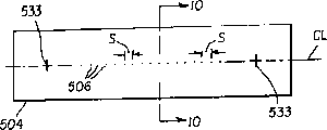
图9表示一个具有沿中心线排列的喷嘴的喷嘴板或结构;Figure 9 shows a nozzle plate or structure with nozzles aligned along the centreline;
图10是沿图9的10-10线的喷嘴板剖视图,并定义了喷嘴的长度尺寸和内部尺寸;Fig. 10 is a sectional view of the nozzle plate along line 10-10 of Fig. 9, and defines the length dimension and internal dimension of the nozzle;
图11表示具有成行列排列的二维喷嘴阵列的喷嘴板;Figure 11 shows a nozzle plate having a two-dimensional array of nozzles arranged in rows and columns;
图12是具有沿中心线排列的喷嘴的圆管状集流腔的示意顶视图;Figure 12 is a schematic top view of a circular tubular manifold with nozzles aligned along the centerline;
图13是圆柱管状集流腔沿图12中剖面线13-13的剖视图,并定义了喷嘴长度尺寸和喷嘴内部尺寸;Fig. 13 is a cross-sectional view of a cylindrical tubular manifold along section line 13-13 in Fig. 12, and defines the nozzle length dimension and nozzle internal dimension;
图13A是改进的圆柱管状集流腔的剖视图,在该集流腔的外壳上形成条状孔上安装有一个弧形喷嘴板;Fig. 13A is a cross-sectional view of an improved cylindrical tubular manifold, in which a strip-shaped hole is formed on the shell of the manifold and an arc-shaped nozzle plate is installed;
图14示意地表示从集流腔上方的喷嘴流出的有机材料蒸气流发散分别与集流腔中的蒸气压力、集流腔中的蒸气压加上惰性气体压力水平之间的关系;Fig. 14 schematically shows the relationship between the divergence of the organic material vapor flow flowing out from the nozzle above the manifold and the vapor pressure in the manifold, the vapor pressure in the manifold plus the pressure level of the inert gas;
图15是一种蒸气源实施方案例如图8中所示的蒸气源的剖视图;Figure 15 is a cross-sectional view of a vapor source embodiment such as the vapor source shown in Figure 8;
图16是图2的LEL气相沉积工位的示意剖视图,并表示衬底从第一位置跨越喷嘴到达第二位置的移动过程;FIG. 16 is a schematic cross-sectional view of the LEL vapor deposition station of FIG. 2 and shows the movement of the substrate from a first position across a nozzle to a second position;
图17是图2的LEL气相沉积工位的一部分的示意顶视图,并示出了在喷嘴板和衬底夹座上的对齐特征,以及在每个衬底沿x方向越过喷嘴之前,沿y方向上标记衬底的标记特征;以及17 is a schematic top view of a portion of the LEL vapor deposition station of FIG. 2 and shows alignment features on the nozzle plate and substrate holder, and along y before each substrate passes the nozzle in the x direction. Marking features in the direction of the marking substrate; and
图18示意地表示集流腔组件,它用于衬底一次通过组件中的喷嘴的过程中对RGB全色有机发光层的同时颜色像素化。Figure 18 schematically shows a manifold assembly for simultaneous color pixelation of RGB full-color organic light-emitting layers in one pass of a substrate through nozzles in the assembly.
这些附图都是示意性的,因为OLEDs中的层厚尺寸通常在亚微米级范围内,而器件的横向特征尺寸却在25-2000毫米的范围内。此外,由于喷嘴板或结构中的多个喷嘴的尺寸相对于喷嘴延伸的长度尺寸很小,附图的比例是为了容易观察而不是为了尺寸精确性给出的。These figures are schematic because layer thickness dimensions in OLEDs are typically in the sub-micron range, while the lateral feature sizes of the devices are in the range of 25-2000 mm. Furthermore, due to the small size of the multiple nozzles in the nozzle plate or structure relative to the length dimension over which the nozzles extend, the scale of the drawings is given for ease of viewing and not for dimensional accuracy.
术语“显示器”或“显示面板”是指一个能够以电子方式显示视频图象或文本的屏幕。术语“像素”是本领域认可的用法,指显示面板上一个能独立于其它区域而被激发发光的区域。术语“多色”用于描述能够在不同区域发射不同颜色光的显示面板。特别地,它指一种能够显示不同颜色图象的显示面板。这些区域并非必须是相邻的。术语“全色”用以描述一种能够发射可见光区的红、绿、蓝色光并能显示任意色调组合的图象的多色显示面板。红、绿、蓝色构成三原色,并且这三种颜色的恰当组合可以产生任何其它颜色。术语“色调”指在可见光谱内的光发射的强度分布,不同的色调表示可视觉辨别的不同颜色。像素和子像素通常表示在显示面板中最小可寻址单位。对单色显示器而言,像素与子像素之间是没有差别的。术语“子像素”被用于多色显示面板中,并指能独立寻址以发射一种特定颜色的光的像素的任一部分。例如蓝色子像素是指能够能发射蓝光的可被寻址的像素。在全色显示器中,一个像素一般包含三原色子像素,即红色、绿色和蓝色,通常缩写为RGB。术语“间距”是指在显示面板中分隔两个像素或子像素间的距离。术语“惰性气体”指一种不与有机蒸气以及在OLED显示器衬底上形成的有机层发生化学反应的气体。The term "display" or "display panel" refers to a screen capable of electronically displaying video images or text. The term "pixel" is an accepted usage in the field, and refers to an area on a display panel that can be excited to emit light independently of other areas. The term "multicolor" is used to describe a display panel capable of emitting light of different colors in different regions. In particular, it refers to a display panel capable of displaying images of different colors. These regions do not have to be contiguous. The term "full-color" is used to describe a multi-color display panel that can emit red, green, and blue light in the visible light region and can display images in any combination of hues. Red, green, and blue make up the three primary colors, and the proper combination of these three colors can produce any other color. The term "hue" refers to the intensity distribution of light emission within the visible spectrum, with different hues denoting different visually discernible colors. Pixels and sub-pixels generally represent the smallest addressable unit in a display panel. For monochrome displays, there is no distinction between pixels and subpixels. The term "subpixel" is used in multicolor display panels and refers to any portion of a pixel that is independently addressable to emit light of a particular color. For example, a blue sub-pixel refers to an addressable pixel capable of emitting blue light. In a full-color display, a pixel generally contains sub-pixels of three primary colors, namely red, green and blue, often abbreviated as RGB. The term "pitch" refers to the distance separating two pixels or sub-pixels in a display panel. The term "inert gas" refers to a gas that does not chemically react with organic vapors and organic layers formed on an OLED display substrate.
具体实施方式Detailed ways
图1表示一个被部分剥离以揭示其内部各层的无源矩阵OLED显示器10的示意性透视图。Figure 1 shows a schematic perspective view of a passive
在透光衬底11上形成多个横向间隔排列的第一电极12(亦称阳极)。通过物理气相沉积依次形成一个有机空穴传输层(HTL)13,一个有机发光层(LEL)14,以及一个有机电子传输层(ETL)15,此过程将在后面更详细地描述。在有机电子传输层15上形成多个横向间隔排列的第二电极16(亦称阴极)。且在与第一电极12基本保持垂直的方向上。一个密封盖或封壳18将器件中对环境敏感的部分密封起来,由此组成一个完整的OLED10。A plurality of first electrodes 12 (also called anodes) are formed on the light-transmitting
如图2所示,表示了一个OLED设备100的示意性透视图,该设备适用于制造较大数量的有机发光器件或显示器,该方法使用自动化或机器人的方法(未示出)在从缓冲中心102和传送中心104延伸出来的多个工位之间传送或转移衬底。经由泵端口107的真空泵106在中心102,104以及从这些中心延伸出来的工位中产生负压,但是工位140除外。压力计108显示在设备100内部的负压值。压力通常小于10-3Torr(1.33×10⁻¹Pa),最低可低至10-6Torr(1.33×10⁻⁴Pa)。As shown in FIG. 2, there is shown a schematic perspective view of an
工位包括:一个用来提供衬底进料的进料工位110,一个用来形成可能包括有机空穴注入子层的有机空穴传输层(HTL)的气相沉积工位130,一个用来形成有机发光层(LEL)的气相沉积工位140,一个用来形成有机电子传输层(ETL)的气相沉积工位150,一个用来形成多个第二电极(阴极)的气相沉积工位160,一个用来从缓冲中心102传送衬底到传送中心104的卸载工位103,其又提供一个储存工位170,以及一个经连接端口105与中心104相连的封装工位180。除了LEL工位140外,每个工位分别有延伸至中心102和104的开放端口,以及一个真空密封接入端口(未示出)以便清洁和更换、维修其中的部件。每个工位都包括一个限定了工作腔的外壳。The stations include: a
在制造OLED显示器中进行有机层颜色像素化的本发明方法中使用了定向射流,该射流是通过将载有有机材料蒸气的惰性气体粘性流引入喷嘴而产生的。基于喷嘴的数目和内部尺寸,以及获得定向射流所需的气体流,LEL工位140的“进气”(gas loading)可以较高。这样的较高进气可能会对OLED设备100其它工位的运行产生不利的影响。In the inventive method for color pixelation of organic layers in the manufacture of OLED displays a directional jet is used, which is generated by introducing a viscous stream of an inert gas laden with organic material vapor into a nozzle. Based on the number and internal dimensions of the nozzles, and the gas flow required to obtain a directional jet, the "gas loading" of the
为了防止对OLED设备100中其它工位或中心的这种潜在不利影响,在颜色像素化过程中,LEL工位140被单独隔离开。这一隔离措施包括:(i)靠近缓冲中心102的虚线所示的工位阀门141,其通常置于闭合位置。工位阀门141只有在将一个衬底从缓冲中心送入工位140中,以及将一个已完成的衬底,即颜色像素化过的衬底从工位140送回到缓冲中心102中时才会开启;和(ii)一个经工位泵端口144与工位140相连的工位真空泵142,该泵还含有一个节流阀145。节流阀可以控制为完全打开、或部分打开或闭合位置。工位压力感应器146能够显示工位140工作腔内的压力。To prevent this potential adverse effect on other stations or centers in the
在传送衬底之前,调整节流阀145使得工位压力感应器146以及OLED设备100上压力计108所显示的压力基本上保持一致,然后打开工位阀门141。Before transferring the substrate, the
在将衬底从中心102传送至工位140的工作腔(140C)中之前,为了能排出工作腔内的残余氧气及湿气,应关闭工位阀门141而开启节流阀145,排空工作腔(140C),使其初始压力在10-7-10-5Torr(1.33×10⁻⁵-1.33×10⁻³Pa)的范围内。Before transferring the substrate from the
在进行颜色像素化之前,惰性气体任选地可从惰性气体供应器147经包括气流控制器149的导管148引入工作腔(140C)中。调节节流阀145至适当位置,使得工作腔内气体压力(Pc)在约10-7-100Torr范围内。工作腔内的压力低于用来在喷嘴(506)中产生粘性流以提供定向射流的惰性气体的压力。Inert gas may optionally be introduced into the working chamber ( 140C) from an
图3是一个沿图2中剖面线3-3的进料工位110的示意剖视图。进料工位110有外壳110H,其限定工作腔110C。在工作腔内安装有用来支撑已经形成第一电极12(参见图1和图4-5)的多个衬底11的支架111。可以提供一种可选择的支架111用来支持多个有源矩阵衬底51(如图7)。在卸载工位103和存储工位170中也可以提供支架111。FIG. 3 is a schematic cross-sectional view of the
图4是一个可通过本发明所述方法进行颜色像素化的全色(RGB)无源矩阵OLED显示器10-3C的示意性顶视图。相同的标记与图1中的描述给出的相同部件或功能相同。每个像素(图4中标示为pix)包含三个相邻的子像素,标记为R、G、B,每个子像素形成于列电极或阳极12与行电极或阴极16的交叉处。每个子像素可被独立寻址并发射特定颜色。例如,标记为R的子像素具有一个可以发射红光的有机EL介质。同样,标记为G和B的子像素具有分别发射绿光和蓝光的有机EL介质。因此,每个像素具有三个可被独立寻址的列电极12(阳极)和一个可被独立寻址的行电极16,且OLED显示器10-3C具有三倍于行电极或阴极16数目的列电极或阳极12。应当注意,图4表示一种简单的列条纹图案,但也可能为更复杂的像素图案布线,如常用的δ图案。Figure 4 is a schematic top view of a full color (RGB) passive matrix OLED display 10-3C that can be color pixelated by the method of the present invention. The same numbers are given to the same components or functions as in the description in FIG. 1 . Each pixel (labeled pix in FIG. 4 ) comprises three adjacent sub-pixels, labeled R, G, B, each formed at the intersection of a column electrode or
图4仅给出了有限数目的像素(pixes)。理论上,像素的数目仅取决于用来制造显示器10-3C的衬底11的尺寸。像素的分辨率,或称为像素的数密度可以非常高,这仅取决于产生颜色像素化的图案化方法的分辨率。使用本发明的定向射流沉积,可以使像素分辨率高达每毫米50个像素。Figure 4 shows only a limited number of pixels. In theory, the number of pixels depends only on the size of the
在一种通常被称为底部发射式的OLED显示器中,产生一种来自OLED显示器10-3C的光发射的选定图案,这种图案可以从透光衬底11的底面观察到。在一种优选的操作模式中,通过依次每次激发一行像素并以选定的速度重复激发顺序来激发面板发光,使得每行的重复激发之间的间隔小于人类视觉系统的检测极限,通常小于约1/60秒。尽管在任一时刻只从一行可寻址的子像素上发光,但观察者所看到的则是由所有被激发的行的光发射所形成的图象。In a type of OLED display commonly referred to as a bottom-emitting type, a selected pattern of light emission from OLED display 10-3C is produced, which pattern can be viewed from the bottom surface of light-
OLED面板10-3C的RGB颜色像素化表示为一种条纹图案,在该图案中,每个R、G和B条仅从激发时一个列电极(阳极)12和一个行电极(阴极)16的交叉点所限定的区域产生发光,尽管像素的定义包括位于阳极12间的非发光缝隙(图4中未标记)。The RGB color pixelation of the OLED panel 10-3C is represented as a striped pattern in which each R, G, and B stripe is drawn only from one column electrode (anode) 12 and one row electrode (cathode) 16 when excited. The area defined by the intersection points emits light, although the pixel definition includes a non-emitting gap (not labeled in FIG. 4 ) between the
图5是沿图4中5-5剖面线的OLED显示器的示意剖视图。EL介质包括以连续层形式存在于在衬底11上提供的阳极列电极12上面和它们之间的有机空穴传输层13。该空穴传输层可以包括首先形成于阳极上面和它们之间的空穴注入子层(未示出)。有机发光子像素层14R、14G和14B形成于空穴传输层上。有机电子传输层1 5以连续层形式形成于颜色像素化层上,并可包括与阴极行电极16接触的重叠电子注入层(未示出)。FIG. 5 is a schematic cross-sectional view of the OLED display along line 5-5 in FIG. 4 . The EL medium comprises an organic
图6描述了一部分有源矩阵OLED显示器的电路图。每个重复的子像素电路包括一个薄膜开关晶体管TSnm,其中n,m是整数,它们定义在透光衬底51(参见图7)上形成的子像素电路的特定位置。例如TS12是与位于第1行的第2位置或者该行的第2列的子像素电路有关的薄膜开关晶体管。每个子像素电路进一步包括一个电源控制的薄膜晶体管TCnm、一个薄膜电容器Cnm以及一个表示为二极管的有机EL介质ELnm。电源供应线Vddn、X方向信号线(包括线X1到Xn,其中n为整数)以及Y方向信号线(包括线Y1到Ym,其中m为整数)分别为每个子像素电路提供电势和信号寻址能力。由信号寻址线X1和Y1-Y3限定的第一行中的电路分别如61-1、61-2、61-3所示,相同的数字标记方法也被用于图7中。X方向信号线X1、X2、X3、...Xn连接到X方向驱动电路87,Y方向信号线Y1、Y2、Y3、...Ym连接到Y方向驱动电路88。为了从EL介质(例如EL12)产生光发射,信号在X方向信号线X1和Y方向信号线Y2上提供,从而开启薄膜开关晶体管TS12置于“接通”状态。接着,电源控制薄膜晶体管TC12也进入“接通”状态并将电流经电源线Vdd1引入有机光致发光介质EL12。这样光就从OLED EL12上发出。Figure 6 depicts a circuit diagram of a portion of an active matrix OLED display. Each repeated sub-pixel circuit includes a thin film switching transistor TSnm, where n and m are integers, which define a specific position of the sub-pixel circuit formed on the light-transmitting substrate 51 (see FIG. 7 ). For example, TS12 is a thin film switching transistor related to the sub-pixel circuit located at the second position of the first row or the second column of the row. Each sub-pixel circuit further includes a power-controlled thin-film transistor TCnm, a thin-film capacitor Cnm, and an organic EL medium ELnm represented as a diode. The power supply line Vddn, the signal line in the X direction (including lines X1 to Xn, where n is an integer) and the signal line in the Y direction (including lines Y1 to Ym, where m is an integer) respectively provide potential and signal addressing for each sub-pixel circuit ability. The circuits in the first row defined by signal addressing lines X1 and Y1-Y3 are shown as 61-1, 61-2, 61-3 respectively, the same numerical notation is also used in FIG. X direction signal lines X1 , X2 , X3 , . In order to generate light emission from the EL medium (eg, EL12), a signal is supplied on the X-direction signal line X1 and the Y-direction signal line Y2, thereby turning on the thin film switching transistor TS12 into an "on" state. Then, the power control thin film transistor TC12 also enters the "on" state and introduces the current into the organic photoluminescent medium EL12 through the power line Vdd1. This way the light is emitted from the OLED EL12.
图7是如图6所示子像素61-1,61-2,61-3的部分的示意剖视图,并表示一个全色像素化的EL介质,在该介质中发光层的RGB颜色像素化分别标记为54R、54G、54B。可由本发明所述方法获得颜色像素化。FIG. 7 is a schematic cross-sectional view of part of the subpixels 61-1, 61-2, 61-3 shown in FIG. Marked as 54R, 54G, 54B. Color pixelation can be obtained by the method described in the present invention.
在透光衬底51上提供子像素电路元件(薄膜晶体管、薄膜电容及电线)61-1,61-2及61-3。导线64提供了(从电源控制薄膜晶体管)到透光第一电极或阳极板52的电连接,该阳极板52可以由铟锡氧化物(ITO)制成。透光有机绝缘层66提供电绝缘。第二有机绝缘层68包围板52的边缘及上表面部分。Sub-pixel circuit elements (thin film transistors, thin film capacitors and wires) 61 - 1 , 61 - 2 and 61 - 3 are provided on the light-transmitting
然后形成有机EL介质,其依次包含以下部分:一个连续的有机空穴注入层和空穴传输层53,颜色像素化的有机发光层54R,54G和54B,以及一个连续的有机电子传输层55。与电子传输层55接触形成共用第二电极或阴极56。子像素发光的有效尺寸如虚线间箭头所示。但一个像素pix不仅仅包括这些发光的部分,还包括在凹陷的发光部分54R,54G和54B之间延伸的非发光凸出部分。The organic EL medium is then formed, which in turn comprises the following parts: a continuous organic hole injection layer and hole transport layer 53 , color pixelated organic light emitting layers 54R, 54G and 54B, and a continuous organic electron transport layer 55 . A common second electrode or cathode 56 is formed in contact with the electron transport layer 55 . The effective size of the light emitting sub-pixels is shown by the arrows between the dotted lines. But a pixel pix includes not only these light-emitting parts, but also non-light-emitting convex parts extending between the recessed light-emitting parts 54R, 54G and 54B.
图8是实施本发明的气相沉积设备500的示意图。图2中的工位140具有外壳140H,其限定保持在如图2说明部分所述的负压Pc下的腔140C。为了保持附图清楚,图8略去了工位阀门141、工位真空泵142和相关的泵端口144和节流阀145、工位压力传感器146以及带导管148的惰性气体源147及气流控制器149。而且,取决于衬底11(51)的材料、集流腔与衬底间的间距以及沉积温度,可能必须对衬底进行冷却,为了方便说明,冷却结构也未示出。FIG. 8 is a schematic diagram of a vapor deposition apparatus 500 embodying the present invention. The
安装在腔140C中的集流腔500M包括集流腔外壳502,其至少一个表面被还称为喷嘴板504的结构密封覆盖。喷嘴板有多个伸入集流腔的喷嘴506。该结构或喷嘴板在一个表面上由对齐标记533,用于在将第一种颜色像素化的有机发光层14R、14G或14B以条纹图案气相沉积在衬底上之前,使OLED显示器衬底11(51)与喷嘴对齐。可以理解的是,衬底11(51)包括有机空穴注入和空穴传输层(HTL)13或53。
在腔140C中的衬底沿y方向通过对齐标记533和在固定衬底的夹座或掩模框230(见图16和17)上提供的对齐窗与喷嘴506对齐时,衬底11(51)通过导向螺杆212(见图16和17)沿x方向移到起点位置“I”。可以理解的是,衬底11(51)或集流腔都可以移动。当然,如果上述元件的任一个是静止不动的,也同样可以完成沉积。When the substrate in the
在腔140C外面安装有多个有机材料蒸气源500VS1至500VS4。为了涂布发光层,蒸气源500VS1至500VS4中的材料至少之一是发光材料。或者,所述多个有机材料蒸气源500VS1至500VS4也可以安装在腔140C和/或集流腔500M的内部。如图8所示意表示以及参考图15更详细描述的,外壳540包括与蒸气源盖544密封匹配的法兰541,接着又密封连接到下蒸气传送导管546a。一个蒸气流控制装置560v在一端连接到下蒸气传送导管546a,在另一端连接到上蒸气传送导管546b。每个蒸气源500VS1至500VS4也优选包含独立的加热元件(图8中未示出),用于加热其中的材料至合适的温度以形成该有机材料的蒸气。或者,所述有机材料可不经所述独立的蒸气源500VS1至500VS4而直接填装至集流腔500M中,并使用直接安装在集流腔500M上面或其内部的加热元件(未画出)形成有机蒸气。A plurality of organic material vapor sources 500VS1 to 500VS4 are installed outside the
惰性气体供应器500IGS有一个气体关闭阀562和一个从气体关闭阀连到惰性气体预热器564的导管(图中未标注),该预热器用于加热该气体到足以防止有机材料蒸气凝结在元件的内表面上,其中惰性气体流和有机材料蒸气流同时存在。下气体传送导管566a把惰性气体预热器连接到气流控制装置560g的一端,上气体传送导管566b把气流控制装置560g的另一端连接到混合器570。混合器570还接受上气体传送导管546b,并把惰性气体流与来自同时运行的两种有机材料蒸气源的至少一部分有机材料蒸气混合起来,如下文进一步描述的。用于蒸气传送和气体传送的共用导管546c通过气相沉积工位140的管壳140H把混合器570的输出端连接到集流腔500M。或者,惰性气体可被直接送入集流腔500M并与传送到那里或在那里产生的有机蒸气混合。The inert gas supply 500IGS has a gas shut-off valve 562 and a conduit (not shown) from the gas shut-off valve to an inert gas preheater 564 for heating the gas sufficiently to prevent condensation of organic material vapors in the On the interior surface of a component, where a flow of inert gas and organic material vapor are present simultaneously. A lower gas delivery conduit 566a connects the inert gas preheater to one end of the gas flow control device 560g, and an upper gas delivery conduit 566b connects the other end of the gas flow control device 560g to the mixer 570. Mixer 570 also receives upper gas delivery conduit 546b and mixes the inert gas flow with at least a portion of the organic material vapor from two simultaneously operating organic material vapor sources, as further described below. A common conduit 546c for vapor delivery and gas delivery connects the output of the mixer 570 to the manifold 500M through the
有机材料蒸气源、惰性气体预热器、流量控制装置、混合器以及传送导管都位于虚线中所示的的可加热部分600。这个可加热部分可以是合适尺寸和形状的实验室炉子,其可以受控加热以提供在所述部分内的温度Te,以防止有机材料蒸气凝结在蒸气源、导管、蒸气流控制装置和混合器570的内表面上。A source of organic material vapor, an inert gas preheater, a flow control device, a mixer, and a transfer conduit are all located in the heatable portion 600 shown in phantom. This heatable section may be a suitably sized and shaped laboratory furnace which may be heated in a controlled manner to provide a temperature Te within said section to prevent condensation of organic material vapors in vapor sources, conduits, vapor flow control devices and mixers 570 on the inner surface.
同样,为了防止有机材料蒸气凝结在集流腔500M的内表面和面朝集流腔的结构或喷嘴板504的表面上,以及防止喷嘴506被凝结的蒸气堵塞,可以使用集流腔加热灯520加热集流腔。图8中并未画出受控加热灯电源和到加热灯520的连接方式。可以领会到,例如在加热集流腔和喷嘴板时可以同样有效使用加热线圈或加热条。Also, to prevent organic material vapors from condensing on the interior surfaces of the manifold 500M and surfaces facing the structure or
意外地发现,如果气流由气流控制装置560g控制使得在集流腔中所得的气体压力导致来自集流腔的气体粘性流动通过喷嘴并进入腔140C,则从喷嘴506排出沿喷嘴轴线具有非常小角度发散的高度定向射流。还发现,有机材料蒸气可与流动的惰性气体在混合器570中混合并被传送到集流腔500M中,并以有机材料与惰性气体的混合定向射流从喷嘴506流出。对于定向气体射流,还证明了,基于喷嘴内部尺寸、气流进入集流腔的量(level)以及在其内部引起的压力增加,定向射流的瞄准距离可以保持在距离喷嘴板504上0.02至2.0厘米。It was surprisingly found that if the gas flow is controlled by the gas flow control device 560g such that the resulting gas pressure in the manifold causes the gas from the manifold to flow viscously through the nozzle and into the
此外还发现,当所述有机物料直接在所述集流腔500M中蒸发时,如果气流由气流控制装置560控制使得在集流腔500M中所产生的气体压力导致从集流腔通过喷嘴并进入工作腔140C的气体粘性流,则从喷嘴506排出具有非常小角度发散的高度定向气体射流。In addition, it is also found that when the organic material is directly evaporated in the manifold 500M, if the gas flow is controlled by the gas flow control device 560 so that the gas pressure generated in the manifold 500M causes the gas to pass through the nozzle from the manifold and enter the The viscous flow of gas in the working
此外还发现,当所述的有机材料是在所述的集流腔500M中直接气化并在其中与惰性气体混合时,如果气流由气流控制装置560g控制使得在集流腔500M中所产生的压力导致从集流腔通过喷嘴并进入工作腔140C的气体粘性流,则从喷嘴506中排出具有非常小角度发散的高度定向气体射流。In addition, it is also found that when the organic material is directly gasified in the manifold 500M and mixed with an inert gas therein, if the gas flow is controlled by the gas flow control device 560g so that the generated in the manifold 500M The pressure causes a viscous flow of gas from the manifold through the nozzle and into the working
为了更好地理解在粘性流条件下流经喷嘴的气流是如何产生一个定向射流的,可以参见由McGraw Hill图书公司于1970年出版的由Leon I.Maissel和Reinhard Glang编著的《薄膜技术手册》(“Handbook of Thin Film Technology”)和由John Wiley & Sons公司出版的由James M.Lafferty编著的《真空科学与技术基础》(”Foundation of Vacuum Science and Technology”)的相关部分。For a better understanding of how the flow of air through a nozzle under viscous flow conditions produces a directional jet, see Handbook of Thin Film Technology, edited by Leon I. Maissel and Reinhard Glang, McGraw Hill Books, 1970 ( "Handbook of Thin Film Technology") and relevant parts of "Foundation of Vacuum Science and Technology", edited by James M. Lafferty, John Wiley & Sons.
当气体流经一个窄管时,它将遇到管壁的阻力。这样在管壁上与其邻近的气流层的流速会被减慢,从而产生了粘性流。粘性因子η是由分子间碰撞所引起的内摩擦所产生的。该粘性因子η可由下式给出:When gas flows through a narrow tube, it encounters resistance from the tube wall. In this way, the flow velocity of the gas flow layer adjacent to it on the pipe wall will be slowed down, resulting in viscous flow. The viscosity factor η results from internal friction caused by intermolecular collisions. The viscosity factor η can be given by the following formula:
其中因子f为0.3-0.5,取决于所假设的分子间相互作用的模型。对大多数气体而言,f=0.499是最理想的假设。σ为分子直径;m为一个气体分子的质量;κB是玻尔兹曼常数;T是气体的温度,以开尔文(K)为单位。where the factor f is 0.3-0.5, depending on the assumed model of intermolecular interactions. For most gases, f = 0.499 is the most ideal assumption. σ is the molecular diameter; m is the mass of a gas molecule; κ B is the Boltzmann constant; T is the temperature of the gas in Kelvin (K).
特别地,当一个惰性气体流经一个长为l半径为r的直圆管时,粘性流的微观流速Qvisc可由下式给出:In particular, when an inert gas flows through a straight circular tube with length l and radius r, the microscopic flow velocity Q visc of the viscous flow can be given by the following formula:
其中p为管内平均压力,p2和p1分别为管中相对两个末端的压力。Where p is the average pressure inside the tube, and p2 and p1 are the pressures at the opposite ends of the tube, respectively.
气体分子的平均自由程λ可以由下式算出:The mean free path λ of gas molecules can be calculated by the following formula:
(3)(3)
其中σ为分子直径,n为单位体积分子数,P为气体压力。Where σ is the molecular diameter, n is the number of molecules per unit volume, and P is the gas pressure.
当气体流经直径为d的导管时,一般存在自由分子流、连续流或粘性流以及过渡流三种流态。用Knudsen数Kn来表征流态:When gas flows through a conduit with a diameter d, there are generally three flow states: free molecular flow, continuous flow or viscous flow, and transition flow. The flow state is characterized by the Knudsen number Kn:
Kn=λ/d (4)Kn=λ/d (4)
当Kn>0.5时,流动是自由分子流态。这时其气体动力学主要受分子与管壁或容器壁的碰撞的支配,气体分子通过不断与管壁撞击直至其与管壁完成最后一次撞击并被弹到开放的空间中流经管路。基于导管长度与直径比的不同,发射分子的角度分布在从余弦θ分布(对零长度而言)到强射流分布(对大的长径比而言)(具体参见Lafferty)。即便在强射流的情况下,在与管轴成非零角度的方向,仍然有显著的发射流量的分量。当0.01<Kn<0.5时,流动是过渡流态,其中,分子间碰撞以及分子与管壁的碰撞都将影响气体流的特性。当Kn更低时,流动将接近粘性流态,这时气体流将主要受分子间碰撞的支配。当Kn<0.01时,流动是粘性流态。这里,与管径相比,气体的平均自由程要小,因此分子间碰撞远比其与管壁碰撞更频繁。当用粘性流态操作时,从管口流出的气体通常以与管口的管壁平行的流线型平稳流出,并且在大的长径比时可以被高度定向。When Kn>0.5, the flow is a free molecular flow state. At this time, its gas dynamics is mainly dominated by the collision between the molecules and the tube wall or container wall. The gas molecules continuously collide with the tube wall until they complete the last impact with the tube wall and are bounced into the open space to flow through the pipeline. Depending on the length to diameter ratio of the conduit, the angular distribution of the emitted molecules ranges from a cosine theta distribution (for zero length) to a strong jet distribution (for large aspect ratios) (see Lafferty for details). Even in the case of strong jets, there is still a significant component of the emitted flow in directions at non-zero angles to the tube axis. When 0.01<Kn<0.5, the flow is a transitional flow state, in which the collision between molecules and the collision between molecules and the tube wall will affect the characteristics of the gas flow. When Kn is lower, the flow will approach a viscous flow regime, where the gas flow will be dominated by intermolecular collisions. When Kn<0.01, the flow is a viscous flow state. Here, the mean free path of the gas is small compared to the diameter of the tube, so collisions between molecules are much more frequent than collisions with the tube wall. When operating with a viscous flow regime, the gas exiting the orifice usually flows smoothly in streamlines parallel to the orifice wall and can be highly oriented at large aspect ratios.
对于某些可气化的材料,其在有用温度下的蒸气压足够低,以至于对于小的开口很难获得粘性流,例如可以用在制造像素化的OLED显示器中。在这种情况下,一种额外的气体(如仅作为载体的惰性气体)可以用来产生粘性流。For some vaporizable materials, the vapor pressure at useful temperatures is low enough that viscous flow is difficult to obtain for small openings, such as can be used in the fabrication of pixelated OLED displays. In this case, an additional gas (such as an inert gas only as a carrier) can be used to create a viscous flow.
气体的蒸气压p*可通过下式估算:The vapor pressure p * of the gas can be estimated by the following formula:
Logp*=A/T+B+ClogT (5)Logp * = A/T+B+ClogT (5)
其中A、B和C为常数。当温度从250变至350℃,测得的Alq的蒸气压从0.024Torr变至0.573Torr。所得最佳拟合系数为A=-2245.996、B=-21.714和C=8.973。在250-350℃范围内的蒸气压下,Alq的平均自由程从0.5mm变至0.0254mm。因此,在250-350℃下在直径为100μm圆形喷嘴结构中,仅靠Alq的蒸气压不足以产生粘性流。对于Alq和这种管子直径,需要大约15Torr的蒸气压才能进入粘性流态。Where A, B and C are constants. When the temperature changes from 250 to 350°C, the measured vapor pressure of Alq changes from 0.024 Torr to 0.573 Torr. The resulting best fit coefficients were A=-2245.996, B=-21.714 and C=8.973. The mean free path of Alq varies from 0.5mm to 0.0254mm at vapor pressure in the range of 250-350°C. Therefore, the vapor pressure of Alq alone is not sufficient to generate viscous flow at 250–350 °C in a circular nozzle structure with a diameter of 100 μm. For Alq and this tube diameter, a vapor pressure of about 15 Torr is required to enter a viscous flow regime.
蒸气流控制装置560v和气流控制装 560g可以是手动调节的流量控制阀。或者,这些流量控制装置也可以是质流控制装置,它可以从关闭位置到开启位置随控制器提供的电控制信号以分级方式进行调节,反过来,电控制信号又可通过电脑(未示出)所发出的信号进行寻址。The vapor flow control device 560v and the air flow control device 560g may be manually adjusted flow control valves. Alternatively, these flow control devices can also be mass flow control devices that can be adjusted in stages from a closed position to an open position with electrical control signals provided by a controller, which in turn can be controlled by a computer (not shown). ) for addressing.
一种有机材料蒸气源例如蒸气源500VS4用一种可气化的有机基质材料填装。这种有机基质材料可以是粉末状、片状、颗粒状或液态。如果要制备一种全色(RGB)OLED显示器,每种剩余的有机材料蒸气源例如500VS1、500VS2、500VS3用不同的可气化有机掺杂剂材料填装。例如,蒸气源500VS1用一种掺杂剂材料填装,该掺杂剂材料提供从有机基质材料的像素化的掺杂层14G中发出的绿光。蒸气源500VS2可以用一种掺杂剂材料填装,该掺杂剂材料提供从有机基质材料的像素化的掺杂层14R中发出的红光。蒸气源500VS3容纳一种掺杂剂材料,该掺杂剂材料提供从有机基质材料的像素化掺杂层14B中发出的蓝光。有机掺杂剂材料可以是粉末状、片状、颗粒状或液态。An organic material vapor source such as vapor source 500VS4 is packed with a vaporizable organic matrix material. This organic matrix material can be in powder, flake, granular or liquid form. If a full color (RGB) OLED display is to be produced, each remaining source of organic material vapor, eg 500VS1, 500VS2, 500VS3, is filled with a different vaporizable organic dopant material. For example, vapor source 500VS1 is filled with a dopant material that provides green light emitted from pixelated doped layer 14G of organic matrix material. Vapor source 500VS2 may be filled with a dopant material that provides red light emission from pixelated doped
使用上面描述的蒸气源的例子以及有机材料的各自填装,按照下面的方法操作气相沉积设备500,可以在衬底11或衬底51上提供全色像素化,这里被描绘成发光层14R(或14G,或14B)的条纹图案。将蒸气源500VS2(红色掺杂剂)和蒸气源VS4(基质材料)加热至气化温度,以使各种有机材料气化,通常通过升华。启动相应的蒸气流控制装置560v,使得受控掺杂剂蒸气流和受控基质蒸气流分别从这两个蒸气源中流经上、下蒸气输送管(分别为560a和560b),混合器570和共用导管546c进入集流腔500M,其中达到基质材料蒸气和掺杂剂材料蒸气的完全“分子混合”。在Alq的250-350℃的升华范围内,这些有机材料的蒸气使得在集流腔内产生大约为0.024-0.573Torr的蒸气压Pv,如结合图14更详细描述的。Using the above-described examples of vapor sources and respective loadings of organic materials, operating vapor deposition apparatus 500 as follows, can provide full-color pixelation on
惰性气体流,例如氮气或氩气,通过在开启惰性气体源500IGS内的气体闭合阀562时通过控制气流控制装置560g的开口而放出的。流动的惰性气体在惰性气体预热器564中预热,预热后的惰性气体经用于蒸气输送和气体输送的上、下气体输送管(分别为566a和566b)、混合器570、并经共用导气管546c进入集流腔500M。惰性气体在集流腔内提供气压PG,将气压PG调整(通过气流控制装置500g)到足以通过在结构或喷嘴板504中的喷嘴506产生粘性流,并提供明显定向的惰性气体射流,其输送引入集流腔中的有机材料混合蒸气,以获得有机材料蒸气和惰性气体的定向射流510。A flow of inert gas, such as nitrogen or argon, is vented by controlling the opening of the gas flow control device 560g when opening the gas shut-off valve 562 within the inert gas source 500IGS. The flowing inert gas is preheated in the inert gas preheater 564, and the preheated inert gas passes through the upper and lower gas delivery pipes (566a and 566b, respectively) for vapor delivery and gas delivery, the mixer 570, and through Common airway 546c enters manifold 500M. The inert gas provides the gas pressure PG within the manifold, adjusting the gas pressure PG (via the gas flow control device 500g) to be sufficient to generate viscous flow through the
OLED显示器衬底11(51)此前已经与喷嘴506对齐,这种对齐是通过喷嘴板上沿y方向的对齐标记533和用于固定衬底的夹座或掩模框230(图8中未示出,见图16和17)上的相应对齐窗进行。衬底在沿x方向移过经过定向射流510,以便在指定的子像素中以条形图案形式接受有机红光发射层14R。这种条纹图案是通过将衬底从始发位置“I”移动到终止为止“II”的前进动作“F”提供的。或者,可以固定衬底位置并使集流腔相对于该衬底移动。The OLED display substrate 11 (51) has previously been aligned with the
现在关闭相应的气流控制装置560v并停止加热蒸气源500VS2,以停止蒸气源500VS4(基质材料)和蒸气源500VS2(红色掺杂剂)的蒸气流。流入集流管和通过喷嘴的预热气流可以继续,或者通过关闭气体流动控制装置560g来停止。此外,在从位置“II”到位置“I”的返回动作“R”过程中,可以在喷嘴板上安置一个闸板装置(见图16),以防止残余的蒸气流或者残余的定向射流到达衬底。The respective gas flow control device 560v is now closed and the heating of vapor source 500VS2 is stopped to stop the vapor flow of vapor source 500VS4 (host material) and vapor source 500VS2 (red dopant). The flow of preheated gas into the header and through the nozzles can continue or be stopped by closing the gas flow control device 560g. In addition, during the return action "R" from position "II" to position "I", a shutter device (see Figure 16) can be placed on the nozzle plate to prevent residual vapor flow or residual directional jet from reaching substrate.
现在衬底11(51)通过一个返回动作“R”从位置“II”回到始发位置“I”。加热蒸气源500VS1(绿色掺杂剂)使该掺杂剂材料升华,并通过连接在500VS1上的气流控制装置560v将“绿色”掺杂剂蒸气引入集流腔。重复将基质材料蒸气流从蒸气源500VS4引入集流腔,并通过使预热惰性气体流入集流腔500M以产生喷嘴506中的粘性流,从而产生定向射流501的步骤。在位置“I”,衬底被重新取向或与喷嘴校准,使得指定接收有机绿光发射层14G的子像素与喷嘴对齐。然后衬底按照前进方向“F”运动,经过从喷嘴506发出的定向射流到达位置“II”,并在指定的子像素上以条纹图案方式接收有机绿光发射层14G。The substrate 11 (51) now returns from the position "II" to the starting position "I" by means of a return action "R". A heated vapor source 500VS1 (green dopant) sublimates the dopant material and introduces "green" dopant vapor into the manifold through a gas flow control device 560v connected to 500VS1. The steps of introducing a stream of matrix material vapor into the manifold from vapor source 500VS4 and creating directional jet 501 by flowing a preheated inert gas into manifold 500M to create viscous flow in
经蒸气源500VS3(蓝色掺杂剂)和蒸气源500VS4(基质材料)的蒸气流,在衬底11(51)的指定子像素区域上以条纹图案接收有机蓝光发射层14B,重复上述过程。这样,如果希望,则通过本发明方法在气相沉积设备500可以制造全色RGB颜色像素化的OLED显示器10-3C或50-3C。Through the vapor flow of vapor source 500VS3 (blue dopant) and vapor source 500VS4 (matrix material), the organic blue light-emitting layer 14B is received in a stripe pattern on the designated sub-pixel area of the substrate 11 (51), and the above process is repeated. Thus, if desired, a full-color RGB color pixelated OLED display 10-3C or 50-3C can be fabricated at the vapor deposition apparatus 500 by the method of the present invention.
可以领会到,使用本发明的方法也可以同样有效地制造多色OLED显示器。具有与选定行(或列)子像素对应排列的喷嘴506的结构或喷嘴板504用于该目的。It will be appreciated that multicolor OLED displays can also be fabricated equally efficiently using the method of the present invention. A structure or
图8及其说明部分还包含了四个蒸气源500VS1到500VS4,可以理解的是,在实施本发明的颜色像素化方法中可以使用更多或更少的蒸气源。此外,蒸气源中所填装的可蒸发材料的选择也可以不同于图8及其说明部分的内容。例如,在第一蒸气源中填装第一种可气化的有机基质材料,第二蒸气源中可以容纳第二种可气化的有机基质材料。第三蒸气源,或第三和附加的蒸气源中则可以填装有机掺杂剂材料,选择这些掺杂剂材料从一个运行的OLED显示器中的掺杂有机发光层图案发射红、绿和蓝色光。Figure 8 and its description also include four vapor sources 500VS1 to 500VS4, it being understood that more or fewer vapor sources may be used in practicing the color pixelation method of the present invention. In addition, the choice of vaporizable material filled in the vapor source can also be different from that shown in Figure 8 and its description. For example, a first vaporizable organic matrix material may be filled in the first vapor source, and a second vaporizable organic matrix material may be contained in the second vapor source. The third vapor source, or third and additional vapor sources, can then be filled with organic dopant materials selected to emit red, green and blue from the pattern of doped organic emissive layers in an operating OLED display Shade.
在形成掺杂有机发光层中使用两种有机基质材料和一种或多种有机掺杂剂材料可以提高运行的OLED显示器的操作稳定性、或者改善光发射、改善发光颜色、或者这些改善特征的组合。The use of two organic matrix materials and one or more organic dopant materials in forming a doped organic light-emitting layer can improve the operational stability of a running OLED display, or improve light emission, improve emission color, or any of these improved characteristics. combination.
可以在蒸气源中填装一种或多种可气化有机掺杂剂材料。The vapor source can be packed with one or more vaporizable organic dopant materials.
在完成颜色像素化时,通过停止加热蒸气源,关闭所有的蒸气源,通过关闭气体关闭阀562或者通过控制气流控制装置560g的闭合来切断惰性气流。加工好的衬底沿x方向从位置“II”回到位置“I”。经如图2所述的工位阀门141,衬底11(51)在该最后位置从工作腔140C移出。一旦流入工作腔的惰性气流被切断,工作腔140C就被抽空(由工位真空泵142经节流阀145抽气),直至其与图的缓冲中心102中的压力相同。颜色像素化后的衬底然后被送入工位150(ETL)中以沉积可以包括电子注入子层的有机电子传输层。When color pixelation is complete, the inert gas flow is shut off by discontinuing the heating vapor source, turning off all vapor sources, by closing the gas shut-off valve 562 or by controlling closure of the gas flow control device 560g. The processed substrate returns from position "II" to position "I" along the x-direction. The substrate 11 ( 51 ) is removed from the working
如图9所示,结构或喷嘴板504在沿其中心线CL上排列有多个喷嘴506。选择在喷嘴间等距离的喷嘴间距,以产生准确涂敷OLED显示器的希望子像素所必需的沉积图案。喷嘴506的总数与OLED显示器的子像素总数一致,OLED显示器的子像素指定发射选定颜色的光,例如红光、绿光、蓝光。这里表示了对齐十字线形式的对齐标记533,但是也可以使用其它的对齐标记。As shown in FIG. 9, the structure or
图10是图9中喷嘴板沿10-10轴线的剖视图。并表示了喷嘴内部尺寸或喷嘴直径d和喷嘴长度尺寸。喷嘴506可以为环形,也可为多边形外形。喷嘴内部尺寸d可在10-1000微米范围内,如果喷嘴长度尺寸l比喷嘴内部尺寸d大至少5倍,则可形成有机材料蒸气和惰性气体的定向射流510(见图8)。Fig. 10 is a cross-sectional view of the nozzle plate in Fig. 9 along the axis 10-10. And indicated the nozzle internal size or nozzle diameter d and nozzle length dimension. The
图11表示一个结构或喷嘴板504T,其包括喷嘴506的二维阵列和对齐标记533。喷嘴阵列504T用m列喷嘴和n行喷嘴描述。这种喷嘴板504T可以密封安装在合适大小的集流腔的一个面上。可以在喷嘴阵列504T和用来容纳颜色像素化的OLED显示器衬底之间安置一个闸板装置,使得闸板装置挡住喷嘴506和衬底之间的视线。衬底通过对齐标记533和容纳和输送衬底的夹座或掩模框230上形成的相应对齐窗233(见图16,17)与喷嘴对齐。衬底移动到喷嘴板504T上方并与之对齐。然后将闸板装置移开,在衬底的离散的和选定的子像素上,惰性气体和有机基质材料以及成色掺杂剂材料的蒸气的定向射流形成掺杂的有机发光层(如层14R、或层14G、或层14B),这明显不同于衬底经过定向射流产生条纹图案的颜色像素化的连续移动方式。FIG. 11 shows a structure or nozzle plate 504T that includes a two-dimensional array of
图12为一个圆管状集流腔500CM的示意顶视图。集流腔500CM有一个圆筒状集流腔外壳536,其包括两端的盖子538和539。集流腔加热元件520穿过集流腔并由两端盖子支撑。多个喷嘴506沿中心线CL以线状图案直接形成在外壳536中。在圆柱表面有对齐标记535并沿中心线CL安置。Figure 12 is a schematic top view of a circular tubular manifold 500CM. Manifold 500CM has a cylindrical manifold housing 536 that includes caps 538 and 539 at both ends. The
图13是圆筒状集流腔沿图12中剖面线13-13的剖视图,并限定了喷嘴长度尺寸l和喷嘴内部尺寸d。喷嘴内部尺寸d可在10到1000微米的范围内,喷嘴的长度应该比喷嘴直径大至少5倍。也可使用其它样式的管状集流腔,比如其横剖面为椭圆形或者多边形。Fig. 13 is a cross-sectional view of the cylindrical manifold along section line 13-13 in Fig. 12, and defines the nozzle length dimension l and the nozzle inner dimension d. The nozzle internal dimension d may be in the range of 10 to 1000 microns, the length of the nozzle should be at least 5 times greater than the diameter of the nozzle. Other styles of tubular manifolds, such as oval or polygonal cross-sections, may also be used.
图13A是改进的圆柱状集流腔500CM-1的剖视图,其中,在该集流腔的外壳536上的缝隙状孔537上封接有一个弧形结构或弧形喷嘴板504C。在弧形喷嘴板504C沿如图12所示的喷嘴线所示的线上形成许多喷嘴。在弧形喷嘴板上提供对齐标记535(图13A中未示出)。FIG. 13A is a cross-sectional view of an improved cylindrical manifold 500CM-1, in which an arc-shaped structure or arc-shaped nozzle plate 504C is sealed to the slit-shaped hole 537 on the shell 536 of the manifold. A number of nozzles are formed on the arcuate nozzle plate 504C along lines indicated by nozzle lines shown in FIG. 12 . Alignment marks 535 (not shown in Figure 13A) are provided on the curved nozzle plate.
图14是关于从喷嘴506射出的有机材料蒸气流发散分别与集流腔外壳502内的蒸气压Pv、以及集流腔500M内蒸气压Pv与惰性气体压PG1和PG2之和的关系的示意图。发散情况如图中虚线箭头所示,且角α1、α2和α3为从喷嘴板504上的喷嘴506所流出蒸气分散所覆盖的角度。工作腔140C中的负压Pc,包括进入腔中惰性气体压力,在10-7-100Torr的范围内。Fig. 14 is about the relationship between the divergence of the organic material vapor flow emitted from the
在没有惰性气体流入集流腔500M之前,有机基质材料和掺杂剂的蒸气从各个蒸气源中进入集流腔,在有机材料蒸气源中在约300℃的升华温度下,在集流腔中形成约0.1Torr(13Pa)的蒸气压Pv。在该蒸气压下的这种有机材料蒸气提供通过喷嘴506的非粘性流并且在进入工作腔中时会有较高的分散,其所覆盖的角度如α1所示。当惰性气体流附加地被引入集流腔并产生气体压力PG1时,从喷嘴发出的蒸气流加上惰性气体流的发散效应被减小,如张角α2所示。表明引入惰性气体流将产生一定水平的粘性流。当流入集流腔500M的惰性气体进一步增加,使集流腔中气体压力PG2>PG1时,从喷嘴506发出的蒸气流和惰性气流的分散效应被进一步减小,提供一种基本定向的射流,其张角为α3。表明对粘性流起实质影响的是集流腔500M中后一气体的压力水平。Before no inert gas flows into the manifold 500M, the vapors of the organic matrix material and the dopant enter the manifold from the respective vapor sources, in the organic material vapor source at a sublimation temperature of about 300°C, in the manifold A vapor pressure Pv of about 0.1 Torr (13 Pa) is formed. This organic material vapor at this vapor pressure provides a non-viscous flow through the
图15是蒸气源500VS实施方案的一个剖视图,蒸气源500VS是示意表示在图8中的蒸气源500VS1-500VS4的代表。蒸气源500VS包括一个带法兰541的外壳540。垫圈542通过螺栓543在法兰541和蒸气源盖544之间提供密封螺栓543提供在法兰和蒸气源盖周边附近。垫圈542可以是由铜、铝等真空技术领域常用金属制成的环形密封圈。15 is a cross-sectional view of an embodiment of vapor source 500VS, which is representative of vapor sources 500VS1-500VS4 shown schematically in FIG. The vapor source 500VS includes a housing 540 with a flange 541 . Gasket 542 provides a seal between flange 541 and vapor source cover 544 via bolt 543. Bolt 543 is provided near the flange and vapor source cover perimeter. The gasket 542 may be an annular sealing ring made of metals commonly used in the field of vacuum technology such as copper and aluminum.
蒸气加热器550伸入外壳540内,由在蒸气源盖中提供的通孔552和554支撑。蒸气加热器550可以加热到蒸发温度,使容纳在蒸气源500VS内的可气化有机材料14a(如虚线轮廓所示)升华,以提供蒸气(未示出)进入到蒸气传送下输送管546a(也见图8)。通过密封材料545将导管密封在蒸气源盖544上。Vapor heater 550 protrudes into housing 540 and is supported by through holes 552 and 554 provided in the vapor source cover. Vapor heater 550 may be heated to a vaporization temperature to sublimate vaporizable organic material 14a (shown in dashed outline) contained within vapor source 500VS to provide vapor (not shown) into vapor delivery lower delivery tube 546a ( See also Figure 8). The conduit is sealed to the vapor source cover 544 by a sealing material 545 .
蒸气加热器电源750经过导线752连到通孔552,再经导线754连到通孔554。用调节器750R控制和调节流经加热器550的电流来实现蒸气加热器550的可控加热。电流计753指示电流大小。The steam heater power supply 750 is connected to the through hole 552 through the lead 752, and then connected to the through hole 554 through the lead 754. Controlled heating of the vapor heater 550 is achieved by controlling and regulating the current flow through the heater 550 with the regulator 750R. The ammeter 753 indicates the magnitude of the current.
通过将螺栓543移开,蒸气源550VS的外壳540可以与蒸气源盖544分开。分开外壳允许清洗有机材料14a的残留物,并填装新的有机材料14a。The housing 540 of the vapor source 550VS can be separated from the vapor source cover 544 by removing the bolt 543 . Splitting the housing allows cleaning of residues of organic material 14a and filling of new organic material 14a.
图16是沿图2剖面线16-16所示的图2的气相沉积工位140(LEL)的示意剖视图,图中省略了蒸气源500VS和惰性气体预热器564。共用导管546c经隔热集流腔支座530伸入集流腔内部,支座530用密封圈532与外壳140H密封。挡板238可以移动到盖住喷嘴506的位置,如图中虚线所示,或者移动到定向射流510(未示出)可以在OLED显示器衬底11(51)上提供颜色像素化的位置。FIG. 16 is a schematic cross-sectional view of the vapor deposition station 140 (LEL) in FIG. 2 along the section line 16-16 in FIG. 2, in which the vapor source 500VS and the inert gas preheater 564 are omitted. The common conduit 546c extends into the manifold through the heat-insulated
OLED显示器衬底11(51)被安装在夹座或掩模框230上,并与喷嘴板504上表面也即喷嘴506的间距为D。滑块225固定连接到夹座230上表面,并且在这里表示为楔形滑块。滑块225与滑轨255R啮合滑动,滑轨装在导螺杆上。The OLED display substrate 11 ( 51 ) is mounted on a holder or
滑块和滑轨使得夹座230及其所携带的衬底11(51)能够沿y方向移动(见图17),并且在如图8所述的每个颜色像素化步骤之前使衬底与喷嘴对齐并标记衬底。The sliders and rails enable the
导螺杆212上啮合导螺杆随动件214,并使其(以及夹座230)沿向前运动“F”的x方向从始发位置“I”移动到终点位置“II”(见图中虚线所示)。在这个连续移动过程中,衬底11(51)移过有机材料蒸气和惰性气体的定向射流(未示出),并以条纹图案方式提供像素化有机层。The
导螺杆212形成在至少有两点固定的导螺杆轴211的部分结构上,即轴密封装置211a安装在工位140的外壳140H上,导螺杆轴端接支架213安装在外壳140H上。The
导螺杆驱动马达210通过开关216提供向前移动“F”或向后运动“R”,开关216经导线217从输入端218向马达提供控制信号。开关216可以有一个中间位置或者“空档”位置(在图16中未示出;见图17),其中,夹座或掩模框230(以及衬底)可以保持在向前运动的终点位置“II”上,或者在起点位置“I”上,其中,从夹座230中取出已经在喷嘴上方完成颜色像素化的衬底并把新的衬底安装在夹座或掩模框中。Lead
对齐检测器234用来通过对齐标记533(或者如果使用圆柱形集流腔500CM则通过对齐标记535)使衬底11(51)与喷嘴板504上的喷嘴506对齐,对齐标记533与位于对齐突块232上的对齐窗233对齐,其中对齐突块232接在夹座或掩模框230上。对齐检测器234通过外壳140H上的光学窗口235并沿光学对齐轴236来检测对齐。其足以提供任何一个对齐标记533的光学对齐。Alignment detector 234 is used to align substrate 11 (51) with
图17表示图2的一部分LEL气相沉积工位140的示意顶视图。集流腔500M被安装在隔热集流腔支座530上。表明对齐突块232连接到夹座或掩模框230上,在这些校准突块中形成的校准窗口233是十字形的,其与喷嘴板504上提供的十字形对齐标记533或者图12的圆柱形集流腔500CM上的十字形对齐标记535一致。FIG. 17 shows a schematic top view of a portion of the LEL
步进马达220有一个驱动轴222,该轴通过马达并通过在外壳140H中形成的轴密封装置233进入工作腔140C。在通过啮合导螺杆随动件214的导螺杆212时夹座230沿x方向运动之前,可以松开连轴器224。连轴器是通过升起连接导通过步进马达220伸出的驱动轴部分的连轴升降杆226松开的。如图17所示,当连轴器224处于啮合位置时,提供驱动轴222的增量旋转,通过滑轨225R(见图16)与滑块225所产生的滑动机制使夹座230前后移动,在计算机221的控制下,步进马达220在y方向上为衬底11(511)供精确的移位。The
如图18所示,示意地表示了一个位于工作腔140C内的集流腔组件500MA。该集流腔组件特别用于在OLED显示器衬底上同时沉积三色图案的有机层。集流腔组件500MA包括三个机械连接的集流腔500MB(用于提供有机基质材料和蓝光发射掺杂剂的蒸气)、500MG(用于提供有机基质材料和绿光发射掺杂剂的蒸气)、以及500MR(用于提供有机基质材料和红光发射掺杂剂的蒸气)。相应的喷嘴506B,506G,506R分别装在集流腔组合件500MA的三个集流腔上,并且它们的间距与精确涂敷OLED显示器衬底11(51)上希望的各个子像素所需的间距保持一致。只有其中一个集流腔提供一或两个对齐标记533。应当指出的是,也可以使用其它的对齐方法。As shown in FIG. 18, a manifold assembly 500MA located in the working
每个集流腔500MB,500MG,500MR从蒸气源,如500VS4中,经过蒸气流控制装置、输送基质材料蒸气源中蒸气和输送惰性气体的共用导管547c,接收有机基质材料蒸气。混合器570混合基质材料蒸气和预热惰性气体并将混合的气体送入共用导管547c。Each manifold 500MB, 500MG, 500MR receives organic matrix material vapor from a vapor source, such as 500VS4, through a vapor flow control device, common conduit 547c for transporting vapor from the source of matrix material vapor, and for transporting inert gas. Mixer 570 mixes matrix material vapor and preheated inert gas and sends the mixed gas into common conduit 547c.
集流腔500MB还接收由如该图所示的蒸气源500VS3提供的“蓝色”掺杂剂蒸气。集流腔500MG还接收如该图所示的蒸气源500VS1提供的“绿色”掺杂剂蒸气。集流腔500MR还接收如该图所示的蒸气源500VS2提供的“红色”掺杂剂蒸气。Manifold 500MB also receives "blue" dopant vapor provided by vapor source 500VS3 as shown in this figure. Manifold 500MG also receives "green" dopant vapor provided by vapor source 500VS1 as shown in this figure. Manifold 500MR also receives "red" dopant vapor provided by vapor source 500VS2 as shown in this figure.
如上所述,衬底11(51)首先与集流管500MG上的对齐标记533取向或对齐。该衬底然后沿x方向移动或传送至起始位置“I”。接着通过喷嘴506B、506G和506R提供定向射流。然后衬底移动经过定向射流到终点位置“II”,以便同时接收颜色像素化的图案,这种图案是分别以红、绿、蓝条纹发光层14R,14G,14B的形式重复出现,并且与OLED显示器衬底11(51)上要形成的指定子像素的列保持一致。可以理解,虽然表示了一种简单的行/列颜色像素化结构,所述的发明可以与挡板挡板、其它几何形状的集流腔和其它相对运动模式结合,产生更复杂的彩色像素沉积图案。As described above, the substrate 11 (51) is first oriented or aligned with the alignment marks 533 on the header 500MG. The substrate is then moved or transported in the x-direction to an initial position "I". Directed jets are then provided through nozzles 506B, 506G, and 506R. The substrate is then moved through the directional jets to terminal position "II" in order to simultaneously receive a color pixelated pattern which is repeated in the form of red, green and blue striped light-emitting
制造该结构或喷嘴板504,504C和504T的优选材料包括金属、玻璃、石英、石墨和陶瓷。集流腔外壳502、536也可以用上述优选材料之一制造。制造集流腔外壳的材料不必与制造喷嘴板的材料相同。例如,集流腔外壳可以用金属制成,而喷嘴板用玻璃制成。Preferred materials for making the structure or
可以理解,尽管本公开仅讨论了PVD方法,但是也可以使用本发明使得前驱体物质被送入集流腔,反应形成新的分子产物,并且这些新产物以希望的方式从喷嘴阵列中放出并沉积在合适的衬底上。It will be appreciated that although this disclosure discusses only PVD methods, the present invention can also be used such that precursor species are fed into a manifold, react to form new molecular products, and these new products are ejected in a desired manner from the array of nozzles and deposited on a suitable substrate.
OLED显示器的其它特征Other Features of OLED Displays
衬底Substrate
OLED显示器通常提供在支撑衬底上,其中OLED显示器的阴极或阳极都可以与衬底接触。通常把与衬底接触的电极称为底电极。通常底电极是阳极,但是本发明并不限于上述结构。衬底可以是透光的或是不透明的,这取决于光发射的预定的方向。透光性是通过底电极观察希望的。在这种情况下通常使用透明的玻璃或者塑料。对于那些从顶电极方向观察光发射的情况,底部支撑物的透光特性并不重要,因而它可以是透光的、光吸收的或者光反射的。在这种情况下所使用的衬底包括但不限于玻璃、塑料、半导体材料、硅、陶瓷和电路板材料。当然,必须在这些器件中提供透明顶电极的结构。OLED displays are typically provided on a support substrate, wherein either the cathode or the anode of the OLED display can be in contact with the substrate. The electrode in contact with the substrate is usually called the bottom electrode. Usually the bottom electrode is the anode, but the invention is not limited to the above structures. The substrate can be light transmissive or opaque, depending on the intended direction of light emission. Light transmission is desirable for viewing through the bottom electrode. Transparent glass or plastic is usually used in this case. For those cases where the light emission is viewed from the direction of the top electrode, the light-transmitting properties of the bottom support are not important, so it can be light-transmitting, light-absorbing or light-reflecting. Substrates used in this context include, but are not limited to, glass, plastics, semiconductor materials, silicon, ceramics, and circuit board materials. Of course, the structure of the transparent top electrode must be provided in these devices.
阳极anode
当通过阳极12或者阳极板52进行观察光发射时,这些电极必须对感兴趣的发射光是透明的或者基本透明的。本发明中所使用的普通透明阳极材料是铟-锡氧化物(ITO)和氧化锡,但也可以使用其它金属氧化物,包括但不限于铝掺杂氧化锌、铟掺杂氧化锌(IZO)、镁-铟氧化物以及镍-钨氧化物。除了上述氧化物外,金属氮化物如氮化镓、金属硒化物如硒化锌、以及金属硫化物如硫化锌都可以用作阳极12(52)。对于那些仅通过阴极观察光发射的情况,阳极的透光特性并不重要,并可使用任何透明的、不透明的或反射的导电材料。用于该用途的导体的实例包括但不限于金、铱、钼、钯和铂。典型的阳极材料,无论透光与否,都具有4.1eV或更大的溢出功。可使用诸如蒸发、溅射、化学气相沉积或电化学手段等任何合适手段来沉积需要的阳极材料。阳极可通过公知的光刻技术进行图案化。When viewing light emission through
空穴注入层(HIL)Hole Injection Layer (HIL)
尽管并非总是必要的,但是在阳极和空穴传输层13(53)间提供一个空穴注入层通常是有用的。空穴注入材料可以用来改善其后续有机层的成膜性,并且有利于将空穴注入到空穴传输层中。合适的空穴注入层材料包括但不限于:如US-A-4,720,432中所述的卟啉化合物、如US-A-6,208,075所述的等离子体-沉积氟碳聚合物、或者如EP 0 891 121 A1和EP 1 029 909 A1中所述的用于有机EL器件的空穴注入材料。Although not always necessary, it is often useful to provide a hole injection layer between the anode and the hole transport layer 13 (53). The hole injection material can be used to improve the film-forming property of the subsequent organic layer, and facilitate the injection of holes into the hole transport layer. Suitable hole injection layer materials include, but are not limited to: porphyrin compounds as described in US-A-4,720,432, plasma-deposited fluorocarbon polymers as described in US-A-6,208,075, or EP 0 891 121 Hole injection materials for organic EL devices as described in A1 and EP 1 029 909 A1.
空穴传输层(HTL)Hole transport layer (HTL)
有机EL显示器的空穴传输层13(53)包含至少一种空穴传输化合物,如芳族叔胺,后者被理解为含有至少一个仅与碳原子相连的三价氮原子且所连碳原子中至少一个为芳环上的组元的化合物。芳族叔胺的一种形式可以是芳基胺,如单芳基胺、二芳基胺、三芳基胺或者聚芳胺。Klupfel等人在美国专利US-A-3,180,730给出了示范性的三芳基胺单体。Brantley等人在US-A-3,567,450和US-A-3,658,520中公开了被一个或多个乙烯基自由基和/或至少含一个活性氢的基团取代的其它合适的三芳基胺。The hole-transporting layer 13 (53) of an organic EL display comprises at least one hole-transporting compound, such as an aromatic tertiary amine, which is understood to contain at least one trivalent nitrogen atom attached to a carbon atom only and the attached carbon atom A compound in which at least one is a component on an aromatic ring. One form of aromatic tertiary amine may be an arylamine, such as a monoarylamine, a diarylamine, a triarylamine, or a polyarylamine. Exemplary triarylamine monomers are given in US-A-3,180,730 by Klupfel et al. Other suitable triarylamines substituted with one or more vinyl radicals and/or groups containing at least one active hydrogen are disclosed by Brantley et al. in US-A-3,567,450 and US-A-3,658,520.
更优选的一类芳族叔胺是如US-A-4,720,432和US-A-5,061,569所述的包括至少两个芳族叔胺部分的那些。这些化合物包括结构式(A)表示的那些:A more preferred class of aromatic tertiary amines are those comprising at least two aromatic tertiary amine moieties as described in US-A-4,720,432 and US-A-5,061,569. These compounds include those represented by structural formula (A):
其中Q1和Q2独立地选自芳族叔胺部分,G为连接基团,如碳-碳键的亚芳基、环亚烷基或亚烷基。在一种实施方案中,Q1或Q2其中至少一个含有多环稠合环结构,如萘。当G为芳基时,通常选自苯基、联苯基或萘基部分。Wherein Q1 and Q2 are independently selected from aromatic tertiary amine moieties, and G is a linking group, such as an arylene group, a cycloalkylene group or an alkylene group of a carbon-carbon bond. In one embodiment, at least one of Q1 or Q2 contains a polycyclic fused ring structure, such as naphthalene. When G is aryl, it is typically selected from phenyl, biphenyl or naphthyl moieties.
一类有用的满足结构式(A)并包含两个三芳基胺部分的三芳基胺化合物用结构式(B)表示:A useful class of triarylamine compounds satisfying formula (A) and comprising two triarylamine moieties are represented by formula (B):

其中:in:
R1和R2彼此相互独立地表示氢、芳基或烷基,或者R1和R2一起表示构成环烷基的原子;以及R 1 and R 2 independently of each other represent hydrogen, aryl or alkyl, or R 1 and R 2 together represent an atom constituting a cycloalkyl group; and
R3和R4彼此相互独立地表示芳基,该芳基又被结构式(C)所示的二芳基取代氨基取代:R 3 and R 4 represent aryl independently of each other, and this aryl is substituted by the diaryl substituted amino group shown in structural formula (C) again:

其中R5和R6是独立地选自芳基。在一种实施方案中,R5或R6中的至少一个含有多环稠合环结构,如萘。Wherein R 5 and R 6 are independently selected from aryl. In one embodiment, at least one of R5 or R6 contains a polycyclic fused ring structure, such as naphthalene.
另一类芳族叔胺是四芳基二胺。理想的四芳基二胺包括两个通过一个亚芳基连接的二芳基氨基基团例如通式(C)所示。有用的四芳基二胺包括式(D)Another class of aromatic tertiary amines is the tetraaryldiamines. Desirable tetraaryldiamines include two diarylamino groups linked by an arylene group such as shown in general formula (C). Useful tetraaryldiamines include formula (D)
表示的那些:Those that represent:
其中:in:
每个Ar可以独立地选自亚芳基,如亚苯基或者蒽部分;Each Ar can be independently selected from arylene groups, such as phenylene or anthracene moieties;
n为1到4的整数;以及n is an integer from 1 to 4; and
Ar、R7、R8和R9独立地选自芳基。在一种典型的实施方案中,Ar、R7、R8和R9中的至少一个是多环稠合环结构,如萘。Ar, R 7 , R 8 and R 9 are independently selected from aryl. In a typical embodiment, at least one of Ar, R7 , R8 and R9 is a polycyclic fused ring structure, such as naphthalene.
前面所述的结构式(A),(B),(C),(D)中的烷基、亚烷基、芳基和亚芳基部分各自又可以被取代。典型的取代基包括烷基、烯基、烷氧基、芳基、芳氧基,以及如氟、氯、溴的卤素。各种烷基、亚烷基部分通常包含约1-6个碳原子。环烷基部分可以包含3-约10个碳原子,但通常它们包含5,6,7个环碳原子——例如环戊基、环己基和环庚基环结构。芳基和亚芳基部分通常是苯基或亚苯基部分。The alkyl, alkylene, aryl and arylene moieties in the aforementioned formulas (A), (B), (C), (D) may in turn each be substituted. Typical substituents include alkyl, alkenyl, alkoxy, aryl, aryloxy, and halogens such as fluorine, chlorine, bromine. The various alkyl, alkylene moieties generally contain about 1-6 carbon atoms. Cycloalkyl moieties can contain from 3 to about 10 carbon atoms, but typically they contain 5, 6, 7 ring carbon atoms - eg cyclopentyl, cyclohexyl and cycloheptyl ring structures. Aryl and arylene moieties are typically phenyl or phenylene moieties.
空穴传输层可由一种芳族叔胺化合物或者它们的混合物制成,特别地,可以由满足式B的三芳基胺和与具有通式D结构的四芳基二胺混合。当三芳基胺与四芳基二胺混合时,后者以一层插入三芳基胺与电子注入和传输层之间。有用的芳族叔胺化合物如下所示:The hole transport layer can be made of one aromatic tertiary amine compound or a mixture thereof, in particular, a triarylamine satisfying formula B and a tetraaryldiamine having a structure of general formula D can be mixed. When triarylamine is mixed with tetraaryldiamine, the latter is inserted as a layer between the triarylamine and the electron injection and transport layer. Useful aromatic tertiary amine compounds are listed below:
1,1-双(4-二-对甲苯基氨基苯基)环己烷1,1-bis(4-di-p-tolylaminophenyl)cyclohexane
1,1-双(4-二-对甲苯基氨基苯基)-4-苯基环己烷1,1-bis(4-di-p-tolylaminophenyl)-4-phenylcyclohexane
4,4`-双(二苯基氨基)四苯4,4`-bis(diphenylamino)tetraphenyl
双(4-二甲基氨基-2-甲基苯基)-苯基甲烷Bis(4-dimethylamino-2-methylphenyl)-phenylmethane
N,N,N-三-(对甲苯基)胺N,N,N-tris-(p-tolyl)amine
4-(二-对甲苯基氨基)-4`-[4-(二-对甲苯基氨基)-苯乙烯基]-芪4-(two-p-tolylamino)-4`-[4-(two-p-tolylamino)-styryl]-stilbene
N,N,N`,N`-四-对甲苯基-4-4`-二氨基联苯N,N,N`,N`-tetra-p-tolyl-4-4`-diaminobiphenyl
N,N,N`,N`-四苯基-4,4`-二氨基联苯N,N,N`,N`-tetraphenyl-4,4`-diaminobiphenyl
N,N,N`,N`-四-1-萘基-4,4`-二氨基联苯N,N,N`,N`-Tetrakis-1-naphthyl-4,4`-diaminobiphenyl
N,N,N`,N″-四-2-萘基-4,4`-二氨基联苯N,N,N`,N″-tetrakis-2-naphthyl-4,4`-diaminobiphenyl
N-苯基咔唑N-phenylcarbazole
4,4`-双[N-(1-萘基)-N-苯基氨基]联苯4,4`-bis[N-(1-naphthyl)-N-phenylamino]biphenyl
4,4`-双[N-(1-萘基)-N-(2-萘基)氨基]联苯4,4`-bis[N-(1-naphthyl)-N-(2-naphthyl)amino]biphenyl
4,4″-双[N-(1-萘基)-N-苯基氨基]对三联苯4,4″-bis[N-(1-naphthyl)-N-phenylamino]-terphenyl
4,4`-双[N-(2-萘基)-N-苯基氨基]联苯4,4`-bis[N-(2-naphthyl)-N-phenylamino]biphenyl
4,4`-双[N-(3-苊基)-N-苯基氨基]联苯4,4`-bis[N-(3-acenaphthyl)-N-phenylamino]biphenyl
1,5-双[N-(1-萘基)-N-苯基氨基]萘1,5-bis[N-(1-naphthyl)-N-phenylamino]naphthalene
4,4`-双[N-(9-蒽基)-N-苯基氨基]联苯4,4`-bis[N-(9-anthracenyl)-N-phenylamino]biphenyl
4,4″-双[N-(1-蒽基)-N-苯基氨基]-对四联苯4,4″-bis[N-(1-anthracenyl)-N-phenylamino]-p-quaterphenyl
4,4`-双[2-(2-菲基)-N-苯基氨基]联苯4,4`-bis[2-(2-phenanthrenyl)-N-phenylamino]biphenyl
4,4`-双[N-(8-荧蒽基)-N-苯基氨基]联苯4,4`-bis[N-(8-fluoranthenyl)-N-phenylamino]biphenyl
4,4`-双[N-(2-芘基)-N-苯基氨基]联苯4,4`-bis[N-(2-pyrenyl)-N-phenylamino]biphenyl
4,4`-双[N-(2-并四苯基)-N-苯基氨基]联苯4,4`-Bis[N-(2-tetraphenyl)-N-phenylamino]biphenyl
4,4`-双[N-(2-苝基)-N-苯基氨基]联苯4,4`-bis[N-(2-perylenyl)-N-phenylamino]biphenyl
4,4`-双[N-(1-蔻基)-N-苯基氨基]联苯4,4`-bis[N-(1-cormonyl)-N-phenylamino]biphenyl
2,6-双[二-对甲苯基氨基]萘2,6-bis[di-p-tolylamino]naphthalene
2,6-双[二-(1-萘基)氨基]萘2,6-bis[di-(1-naphthyl)amino]naphthalene
2,6-双[N-(1-萘基)-N-(2-萘基)氨基]萘2,6-bis[N-(1-naphthyl)-N-(2-naphthyl)amino]naphthalene
N,N,N`,N`-四-(2-萘基)-4,4″-二氨基-对三联苯N, N, N`, N`-tetrakis-(2-naphthyl)-4,4″-diamino-p-terphenyl
4,4`-双{N-苯基-N-[4-(1-萘基)-苯基]氨基}联苯4,4`-bis{N-phenyl-N-[4-(1-naphthyl)-phenyl]amino}biphenyl
4,4`-双[N-苯基-N-(2-芘基)氨基]联苯4,4`-bis[N-phenyl-N-(2-pyrenyl)amino]biphenyl
2,6-双[N,N-二(2-萘基)胺]芴2,6-bis[N,N-bis(2-naphthyl)amine]fluorene
1,5-双[N-(1-萘基)N-苯基氨基]萘1,5-bis[N-(1-naphthyl)N-phenylamino]naphthalene
另一类有用的空穴传输材料包括如EP 1009041所述的多环芳族化合物。此外,聚合空穴传输材料可以使用诸如聚(N-乙烯基咔唑)(PVK)、聚噻吩、聚吡咯、聚苯胺,以及共聚物诸如聚(3,4-乙烯基二氧噻吩)/聚(4-苯乙烯磺酸酯),又称PEDOT/PSS。Another class of useful hole transport materials includes polycyclic aromatic compounds as described in EP 1009041. In addition, polymeric hole transport materials such as poly(N-vinylcarbazole) (PVK), polythiophene, polypyrrole, polyaniline, and copolymers such as poly(3,4-vinyldioxythiophene)/poly (4-styrene sulfonate), also known as PEDOT/PSS.
发光层(LEL)Light emitting layer (LEL)
如美国专利US-A-4,769,292和US-A-5,935,721所详细描述的那样,有机EL显示器的发光层(LEL)14(14R、14G、14B)和54R、54G、54B包括一种发光或荧光材料,其中,由于电子-空穴对在这个区域内复合,因此产生电致发光。发光层可以只由一种材料组成,但是更普遍地,发光层由至少一种用客体化合物或多种化合物(一种掺杂剂或多种掺杂剂)掺杂的基质材料组成,光发射主要来自掺杂剂并且可以具有任何颜色。在发光层中的基质材料可以是如下所定义的电子传输材料、如前所定义的空穴传输材料、或者其它支持空穴-电子复合的材料或者材料的组合。掺杂剂通常选自强荧光染料,但是也可以选自如WO98/55561,WO00/18851,WO00/57676和WO00/70655所述过渡金属配合物的磷光化合物。通常掺杂剂以0.01-10%的重量涂到基质材料中。基质材料也可以选用诸如聚芴、聚乙烯基亚芳基(例如,聚(对亚苯基1,2-亚乙烯基),PPV)等聚合材料。在这种情况下,小分子掺杂剂可以以分子扩散的形式进入聚合物主体中,或者通过次要成分与聚合物共聚的方式加入掺杂剂。As described in detail in US-A-4,769,292 and US-A-5,935,721, the light-emitting layers (LEL) 14 (14R, 14G, 14B) and 54R, 54G, 54B of organic EL displays include a light-emitting or fluorescent material , where electroluminescence occurs due to the recombination of electron-hole pairs in this region. The light-emitting layer may consist of only one material, but more generally the light-emitting layer consists of at least one host material doped with a guest compound or compounds (a dopant or dopants), the light emitting Mainly from dopants and can have any color. The host material in the emissive layer may be an electron transport material as defined below, a hole transport material as defined above, or other material or combination of materials that supports hole-electron recombination. The dopant is usually selected from strongly fluorescent dyes, but may also be selected from phosphorescent compounds of transition metal complexes as described in WO98/55561, WO00/18851, WO00/57676 and WO00/70655. Typically the dopant is applied to the matrix material at 0.01-10% by weight. The matrix material can also be selected from polymeric materials such as polyfluorene, polyvinyl arylene (eg, poly(p-phenylene 1,2-vinylene), PPV). In this case, the small molecule dopant can be incorporated into the polymer host in the form of molecular diffusion, or the dopant can be added through the copolymerization of the minor component with the polymer.
选择染料作为掺杂剂的一个重要关系是带隙电位的比较,带隙电位定义为最高占据分子轨道和最低未占据分子轨道间的能量差。实现能量从主体分子向掺杂剂分子有效转移的必要条件是掺杂剂的带隙电位小于基质材料的带隙电位。An important relationship in the choice of dyes as dopants is the comparison of the bandgap potential, which is defined as the energy difference between the highest occupied molecular orbital and the lowest unoccupied molecular orbital. A necessary condition for efficient energy transfer from host molecules to dopant molecules is that the bandgap potential of the dopant is smaller than that of the host material.
已知有用的基质材料分子和发光掺杂剂分子包括但不限于在下述文献中公开的那些:US-A-4,768,292,US-A-5,141,671,US-A-5,150,006,US-A-5,151,629,US-A-5,405,709,US-A-5,484,922,US-A-5,593,788,US-A-5,645,948,US-A-5,683,823,US-A-5,755,999,US-A-5,928,802,US-A-5,935,720,US-A-5,935,721,以及US-A-6,020,078。Known useful host material molecules and luminescent dopant molecules include, but are not limited to, those disclosed in US-A-4,768,292, US-A-5,141,671, US-A-5,150,006, US-A-5,151,629 , US-A-5,405,709, US-A-5,484,922, US-A-5,593,788, US-A-5,645,948, US-A-5,683,823, US-A-5,755,999, US-A-5,928,802, US-A-5,935,720, US -A-5,935,721, and US-A-6,020,078.
8-羟基喹啉或其类似衍生物(通式E)的金属配合物组成了一类有用的能够支持电致发光的主体化合物,特别适合于波长大于500nm,如绿色、黄色、橙色和红色的光发射。The metal complexes of 8-hydroxyquinoline or its similar derivatives (general formula E) constitute a class of useful host compounds capable of supporting electroluminescence, especially suitable for wavelengths greater than 500nm, such as green, yellow, orange and red light emission.
其中:in:
M代表金属原子;M represents a metal atom;
n是1到4的整数;和n is an integer from 1 to 4; and
Z在每种情况下独立地表示构成具有至少两个稠合芳环的环的原子。Z independently represents in each case an atom constituting a ring having at least two fused aromatic rings.
从前面的描述可知,金属原子可以是一价、二价、三价或者四价的。例如,金属可以是碱金属,如锂、钠或钾;碱土金属,如镁或钙;土金属,如铝、镓;或者过渡金属,如锌、锆。一般来说,可使用已知是螯合金属的任何一价、二价、三价或者四价金属。有用的喔星配合物如下所示:As can be seen from the foregoing description, metal atoms can be monovalent, divalent, trivalent or tetravalent. For example, the metal can be an alkali metal, such as lithium, sodium, or potassium; an alkaline earth metal, such as magnesium or calcium; an earth metal, such as aluminum, gallium; or a transition metal, such as zinc, zirconium. In general, any monovalent, divalent, trivalent or tetravalent metal known to be a chelating metal can be used. Useful oxen complexes are listed below:
CO-1:三喔星铝[又名:三(8-喹啉醇合)铝(III)]CO-1: trioxine aluminum [also known as: tris (8-quinolinol) aluminum (III)]
CO-2:二喔星镁[又名:二(8-喹啉醇合)镁(II)]CO-2: Magnesium dioxine [also known as: bis(8-quinolinolate) magnesium (II)]
CO-3:双[苯并-{f}-8-喹啉醇合]锌(II)CO-3: bis[benzo-{f}-8-quinolinolato]zinc(II)
CO-4:双(2-甲基8-喹啉醇合)铝(III)-μ-氧代-双(2-甲基-8-喹啉醇合)铝(III)CO-4: Bis(2-methyl-8-quinolinolate)aluminum(III)-μ-oxo-bis(2-methyl-8-quinolinolate)aluminum(III)
CO-5:三喔星铟[又名:三(8-喹啉醇合)铟]CO-5: trioxine indium [also known as: tri(8-quinolinol) indium]
CO-6:三(5-甲基喔星)铝[又名:三(5-甲基-8-喹啉醇合)铝(III)]CO-6: Tris (5-methyloxine) aluminum [also known as: tris (5-methyl-8-quinolinol) aluminum (III)]
CO-7:喔星锂[又名:8-喹啉醇合锂(I)]CO-7: Lithium Oxine
CO-8:喔星镓[又名:8-喹啉醇合镓(III)]CO-8: Oxygen gallium [also known as: 8-quinolinol gallium(III)]
CO-9:喔星锆[又名:四(8-喹啉醇合)锆(IV)]CO-9: Oxygen zirconium [also known as: four (8-quinolinol) zirconium (IV)]
9,10-二-(2-萘基)蒽的衍生物(如通式F)组成了一类能够支持电致发光的主体,特别适合于波长大于400nm,如蓝色、绿色、黄色、橙色或红色。9,10-bis-(2-naphthyl)anthracene derivatives (such as general formula F) constitute a class of hosts that can support electroluminescence, especially suitable for wavelengths greater than 400nm, such as blue, green, yellow, orange or red.

其中,R1,R2,R3,R4,R5,R6表示在每个环上的一个或者多个取代基,每个取代基独立地选自下面的组:Wherein, R 1 , R 2 , R 3 , R 4 , R 5 , R 6 represent one or more substituents on each ring, and each substituent is independently selected from the following groups:
第一组:氢、含有1至24个碳原子的烯基、烷基或者环烷基;Group 1: hydrogen, alkenyl, alkyl or cycloalkyl having 1 to 24 carbon atoms;
第二组:含有5至20个碳原子的芳基或者取代芳基;The second group: aryl or substituted aryl containing 5 to 20 carbon atoms;
第三组:4至24个碳原子的稠合芳基,如蒽基、芘基或苊基;The third group: fused aryl groups of 4 to 24 carbon atoms, such as anthracenyl, pyrenyl or acenaphthyl;
第四组:5至24个碳原子的杂芳基或取代杂芳基,如形成呋喃基、噻吩基、吡啶基、喹啉基或者其它杂环系统的稠合杂芳环所必需的;Group IV: heteroaryl or substituted heteroaryl groups of 5 to 24 carbon atoms, as necessary to form furyl, thienyl, pyridyl, quinolinyl or fused heteroaryl rings of other heterocyclic systems;
第五组:1至24个碳原子的烷氧基氨基、烷基氨基或芳基氨基;Group V: alkoxyamino, alkylamino or arylamino groups of 1 to 24 carbon atoms;
第六组:氟、氯、溴或者氰基;Group VI: fluorine, chlorine, bromine or cyano;
说明性的实例包括9,10-二-(2-萘基)蒽和2-叔丁基-9,10-二-(2-萘基)蒽。也可使用其它的蒽衍生物作为LEL的基质材料,包括9,10-双[4-(2,2-二苯基亚乙基)苯基]蒽的衍生物。Illustrative examples include 9,10-di-(2-naphthyl)anthracene and 2-tert-butyl-9,10-di-(2-naphthyl)anthracene. Other anthracene derivatives can also be used as host materials for LELs, including derivatives of 9,10-bis[4-(2,2-diphenylethylidene)phenyl]anthracene.
吲哚衍生物(如通式G)组成了另一类能够支持电致发光的基质材料,特别适合于波长大于400nm的光发射如蓝色、绿色、黄色、橙色或红色。Indole derivatives (such as the general formula G) constitute another class of host materials capable of supporting electroluminescence, especially suitable for light emission with a wavelength greater than 400 nm such as blue, green, yellow, orange or red.
其中:in:
n为3到8的整数;n is an integer from 3 to 8;
Z为O,NR,或S;Z is O, NR, or S;
R和R`独立地选自氢;1到24个碳原子的烷基如丙基、叔丁基、庚基等;5到20个碳原子的芳基或杂芳基如苯基、萘基、呋喃基、噻吩基、吡啶基、喹啉基及其它杂环系统;或者如氯、氟等卤素原子;或者其它组成稠芳环所必须的原子;并且每个吲哚单元上最多有4个R`,R and R' are independently selected from hydrogen; alkyl groups of 1 to 24 carbon atoms such as propyl, tert-butyl, heptyl, etc.; aryl or heteroaryl groups of 5 to 20 carbon atoms such as phenyl, naphthyl , furyl, thienyl, pyridyl, quinolinyl and other heterocyclic ring systems; or halogen atoms such as chlorine and fluorine; or other atoms necessary to form a condensed aromatic ring; and each indole unit has a maximum of 4 R`,
L是由烷基、芳基、取代烷基或者取代芳基组成的连接单元,它以共轭或者非共轭的方式将多个吲哚连接起来。L is a linking unit composed of an alkyl group, an aryl group, a substituted alkyl group or a substituted aryl group, and it connects multiple indoles in a conjugated or non-conjugated manner.
一个有用的吲哚化合物的例子是2,2`,2″-(1,3,5-亚苯基)三[1-苯基-1H-苯并咪唑]。An example of a useful indole compound is 2,2',2"-(1,3,5-phenylene)tris[1-phenyl-1H-benzimidazole].
也可使用如US-A-5,121,029所述的二苯乙烯基亚芳基衍生物作为LEL基质材料。It is also possible to use distyrylarylene derivatives as described in US-A-5,121,029 as LEL matrix materials.
理想的荧光掺杂剂包括蒽、并四苯、呫吨、苝、红荧烯、香豆素、若丹明、喹吖啶酮、二氰基亚甲基吡喃化合物、噻喃化合物、聚甲炔化合物、吡啶鎓和噻喃鎓化合物的衍生物,芴衍生物,periflanthene衍生物,以及碳苯乙烯衍生物。有用的掺杂剂的示范性的例子包括但并不限于以下物质:Ideal fluorescent dopants include anthracene, tetracene, xanthene, perylene, rubrene, coumarin, rhodamine, quinacridone, dicyanomethylenepyran, thiopyran, poly Derivatives of methine compounds, pyridinium and thiopyrylium compounds, fluorene derivatives, periflanthene derivatives, and carbostyrene derivatives. Illustrative examples of useful dopants include, but are not limited to, the following:


电子传输层(ETL)Electron Transport Layer (ETL)
优选的用于形成有机EL显示器的电子传输层15(55)的薄膜材料是金属螯合的喔星化合物,包括喔星化合物自身的螯合物(通常也称为8-喹啉醇或者8-羟基喹啉)。这些化合物能够帮助电子的注入和传送,并具有很高的性能以及很容易制备薄膜。预期的喔星化合物的例子是那些前面已经描述过的结构式(E)的化合物。Preferred film materials for forming the electron transport layer 15 (55) of an organic EL display are metal chelated oxine compounds, including chelates of oxine compounds themselves (usually also called 8-quinolinol or 8- Hydroxyquinoline). These compounds can aid in the injection and transport of electrons, have high performance and are easy to prepare thin films. Examples of contemplated oxine compounds are those compounds of formula (E) which have been described above.
其它的电子传送材料包括公开在US-A-4,356,429中的各种丁二烯衍生物以及如US-A-4,539,507所述的各种杂环荧光增白剂。满足通式(G)结构的吲哚化合物也是有用的电子传送材料。Other electron transport materials include the various butadiene derivatives disclosed in US-A-4,356,429 and the various heterocyclic optical brighteners as described in US-A-4,539,507. Indole compounds satisfying the structure of general formula (G) are also useful electron transport materials.
阴极cathode
当仅从阳极观察光发射时,普通的阳极56或阴极16可以由几乎任何导电材料组成。理想的材料应具有良好的成膜性能,以确保其与下面的有机层保持良好的接触从而促进电子在低电压下注入,并具有良好的稳定性。有用的阴极材料通常包含低溢出功(<4.0eV)的金属或金属合金。描述在US-A-4,885,221中的一种优选的阴极材料由Mg∶Ag合金组成,其中银的百分比在1-20%之间。另一类合适的阴极材料包括由一个与有机层(例如,ETL)接触的薄电子注入层(EIL)双层,在它上面还覆盖有一层更厚的导电金属。这里,EIL优选包括低溢出功金属或其合金,如果这样,更厚的覆盖层不需要具有低溢出功。如US-A-5,677,572所述,这样的阴极通常由一个薄的LiF层以及覆盖在该层上的一个较厚的Al层组成。其它的有用阴极材料装置可以包括但不限于公开在US-A-5,059,861,US-A-5,059,862以及US-A-6,140,763中的那些。When viewing light emission only from the anode, the general anode 56 or
当通过阴极观察光发射时,阴极必须是透明或者基本透明的。在这种情况下,金属必须薄或者必须使用透明的导电氧化物或这些材料的组合。美国专利US-A-5,776,623中更详细地描述了光透明的阴极。阴极材料可以通过蒸发、溅镀或者化学气相沉积的方法来沉积。在需要时,可以使用许多公知的方法来进行图案化,这些方法包括但不限于:贯串掩模(through-mask)沉积法、如US-A-5,276,380和EP 0732868中所述的整体障板沉积法、激光切割法和选择性化学气相沉积法。When viewing light emission through the cathode, the cathode must be transparent or substantially transparent. In this case, the metal must be thin or a transparent conducting oxide or a combination of these materials must be used. Optically transparent cathodes are described in more detail in US-A-5,776,623. The cathode material can be deposited by evaporation, sputtering or chemical vapor deposition. If desired, patterning can be performed using a number of well-known methods including, but not limited to, through-mask deposition, integral mask deposition as described in US-A-5,276,380 and EP 0732868 method, laser cutting method and selective chemical vapor deposition method.
封装encapsulation
大多数OLED器件和显示器对湿气、氧气、或它们两者敏感。因此,通常密封在诸如氮气、氩气的惰性气体气氛中,以及在氧化铝、铝土矿、硫酸钙、粘土、硅胶、沸石、碱金属氧化物、碱土金属氧化物、硫酸盐、或金属卤化物和高氯酸盐等的干燥剂的存在下。封装和干燥的方法包括但不限于,如US-A-6,226,890所述的方法。此外,在现有技术中也使用诸如SiOx、特氟纶,以及本领域已知的可选择无机/聚合物层的阻挡层来进行封装。Most OLED devices and displays are sensitive to moisture, oxygen, or both. Therefore, it is usually sealed in an inert gas atmosphere such as nitrogen, argon, and in alumina, bauxite, calcium sulfate, clay, silica gel, zeolite, alkali metal oxides, alkaline earth metal oxides, sulfates, or metal halides In the presence of desiccants such as substances and perchlorates. Methods of encapsulation and drying include, but are not limited to, those described in US-A-6,226,890. Additionally, barrier layers such as SiOx, Teflon, and alternative inorganic/polymer layers known in the art are also used for encapsulation in the prior art.
本发明的其它特点还包括在下面所述的内容中。Other features of the present invention are also included in the contents described below.
本发明所述的方法包括加热蒸气源表面、连接器件表面、集流腔表面以及所述结构至足够高的温度,以防有机材料的蒸气凝结在这些表面上。The method of the present invention includes heating the surfaces of the vapor source, the surfaces of the connecting device, the surfaces of the manifold, and the structure to a temperature sufficiently high to prevent condensation of organic material vapors on these surfaces.
本发明的方法还包括控制蒸发的有机材料进入集流腔的输送,使得在集流腔中提供一个有机材料的选定蒸气压。The method of the present invention also includes controlling the delivery of the vaporized organic material into the manifold such that a selected vapor pressure of the organic material is provided in the manifold.
该方法包括如下步骤:The method comprises the steps of:
i)提供一个惰性气体源;i) provide a source of inert gas;
ii)预热惰性气体至足够高温度,以防止气化的有机材料凝结在集流腔中及该结构的喷嘴中;ii) preheating the inert gas to a temperature high enough to prevent condensation of vaporized organic material in the manifold and nozzles of the structure;
iii)控制预热惰性气体的压力或者控制惰性气体的流量;以及iii) controlling the pressure of the preheated inert gas or controlling the flow of the inert gas; and
iv)将预热受控的惰性气体流送入集流腔中。iv) Sending a preheated controlled flow of inert gas into the manifold.
该方法包括控制预热惰性气体的压力和流量。The method includes controlling the pressure and flow of preheated inert gas.
该方法包括在一个板状结构或者管状结构内形成多个喷嘴。The method includes forming a plurality of nozzles within a plate-like or tubular structure.
该方法包括沿一条中心线在该结构中形成多个喷嘴,并在衬底上沉积发光有机层的成色条纹图案过程中提供OLED显示器衬底与集流腔间的相对运动。The method includes forming a plurality of nozzles in the structure along a centerline and providing relative motion between an OLED display substrate and a manifold during deposition of a color-forming stripe pattern of a light emitting organic layer on the substrate.
该方法包括在该结构中形成多个喷嘴组成的二维阵列,该阵列与OLED显示器衬底中选定的像素位置保持一致,以在衬底选定的像素位置上提供有机发光层的像素化图案。The method includes forming a two-dimensional array of a plurality of nozzles in the structure aligned with selected pixel locations in the OLED display substrate to provide pixelation of the organic emissive layer at the selected pixel locations on the substrate pattern.
该方法包括加热蒸气源表面、连接器件表面、集流腔表面以及该结构至足够高的温度,以防止有机材料的蒸气凝结在上述器件的表面上。The method includes heating the surface of the vapor source, the surface of the connecting device, the surface of the manifold, and the structure to a temperature sufficiently high to prevent condensation of the vapor of the organic material on the surface of the device.
该方法包括控制气化的第一和第二有机基质材料以及一种或者多种气化的有机掺杂剂进入集流腔,使得在集流腔中提供气化有机材料的选定蒸气压。The method includes controlling the entry of the vaporized first and second organic matrix materials and the one or more vaporized organic dopants into the manifold such that a selected vapor pressure of the vaporized organic material is provided in the manifold.
该方法包括以下步骤:The method includes the following steps:
i)提供一个惰性气体源;i) provide a source of inert gas;
ii)预热惰性气体至足够高温度,以防止气化有机材料凝结在集流管及该结构的喷嘴中;ii) preheating the inert gas to a temperature high enough to prevent condensation of vaporized organic material in the header and nozzles of the structure;
iii)控制预热惰性气体的压力或者控制惰性气体的流量;以及iii) controlling the pressure of the preheated inert gas or controlling the flow of the inert gas; and
iv)将预热且受控的惰性气体流送入集流腔中。iv) A preheated and controlled flow of inert gas is fed into the manifold.
该方法包括在板状结构或者管状结构内形成多个喷嘴。The method includes forming a plurality of nozzles within a plate-like structure or a tubular structure.
该方法包括沿一条中心线在该结构中形成多个喷嘴,并在衬底上沉积第一、第二、第三有机发光层的三色条状图案的过程中,提供OLED显示器衬底与集流腔间的相对运动。The method includes forming a plurality of nozzles in the structure along a centerline, and providing an OLED display substrate with a set of Relative motion between flow chambers.
该方法包括在该结构内部形成由多个喷嘴组成的二维阵列,该阵列与OLED显示器衬底上的像素位置保持一致,以在衬底上的相应像素位置中提供第一、第二、第三有机发光层的像素化图案。The method includes forming within the structure a two-dimensional array of a plurality of nozzles aligned with pixel locations on the OLED display substrate to provide first, second, third, and second nozzles in corresponding pixel locations on the substrate. Pixelated pattern of three organic light-emitting layers.
该方法包括在该结构中形成由多个喷嘴组成的二维阵列,该阵列与OLED显示器上选定的像素位置一致,以在衬底的选定像素位置上提供有机发光层的像素化图案。The method includes forming a two-dimensional array of a plurality of nozzles in the structure that coincides with selected pixel locations on the OLED display to provide a pixelated pattern of an organic light emitting layer at the selected pixel locations on the substrate.
该方法包括加热蒸气源表面、连接器件表面、集流腔表面以及该结构至足够高的温度,以防止有机材料的蒸气凝结在这些表面上。The method includes heating the surfaces of the vapor source, the surfaces of the connecting device, the surfaces of the manifold, and the structure to a temperature sufficiently high to prevent condensation of the vapor of the organic material on the surfaces.
该方法还包括选择第一成色、第二成色和第三成色有机掺杂剂材料,以便分别从操作的OLED显示器的掺杂有机发光层的相应图案中产生红、绿、蓝色光发射。The method also includes selecting the first color-forming, second color-forming, and third color-forming organic dopant materials to produce red, green, and blue light emissions, respectively, from corresponding patterns of doped organic light-emitting layers of the operating OLED display.
该方法还包括控制气化的有机发光材料进入集流腔的输送,使得在集流腔中提供有机材料的选定蒸气压。The method also includes controlling delivery of the vaporized organic light emitting material into the manifold such that a selected vapor pressure of the organic material is provided in the manifold.
该方法包括以下步骤:The method includes the following steps:
i)提供一个惰性气体源;i) provide a source of inert gas;
ii)预热惰性气体至足够高温度,以防止有机材料的蒸气凝结在集流管及该结构的喷嘴中;ii) preheating the inert gas to a temperature high enough to prevent condensation of organic material vapors in the header and nozzles of the structure;
iii)控制预热惰性气体的压力或者控制惰性气体的流量;以及iii) controlling the pressure of the preheated inert gas or controlling the flow of the inert gas; and
iv)将预热受控的惰性气体流送入集流腔中。iv) Sending a preheated controlled flow of inert gas into the manifold.
该方法包括控制预热惰性气体的流量或者压力,使得集流腔内惰性气体的压力比流入集流腔的有机材料的蒸气压高。The method includes controlling the flow or pressure of the preheated inert gas so that the pressure of the inert gas in the manifold is higher than the vapor pressure of the organic material flowing into the manifold.
一种在OLED显示器衬底上以三色图案方式同时沉积有机发光层的方法,包括以下步骤:A method for simultaneously depositing an organic light-emitting layer in a three-color pattern on an OLED display substrate, comprising the following steps:
a)在减压的工作腔内提供一个集流腔组件和OLED显示器衬底,并且彼此间隔排列,所述的集流腔组件包括第一集流腔、第二集流腔和第三集流腔;a) A manifold assembly and an OLED display substrate are provided in the decompressed working chamber, and are spaced apart from each other, and the manifold assembly includes a first manifold, a second manifold and a third manifold Cavity;
b)提供封接在每个第一、第二、第三集流腔的至少一个表面的独立结构,每个独立结构包括延伸通过该结构伸入相应的集流腔的多个喷嘴,每个独立结构中的喷嘴相互间隔排列并与沉积在OLED显示器衬底上的三色图案相对应;b) providing a self-contained structure sealed to at least one surface of each of the first, second and third manifolds, each self-contained structure comprising a plurality of nozzles extending through the structure into the corresponding manifold, each The nozzles in the individual structures are arranged at intervals and correspond to the three-color pattern deposited on the OLED display substrate;
c)使OLED显示器的衬底朝向其中一个独立结构的喷嘴;c) orienting the substrate of the OLED display towards the nozzle of one of the individual structures;
d)同时将用于形成第一种颜色的气化有机发光材料送入第一集流腔、将用于形成第二种颜色的气化有机发光材料送入第二集流腔、将用于形成第三种颜色的气化有机发光材料送入第三集流腔;以及d) At the same time, the gasified organic luminescent material used to form the first color is sent into the first manifold, the gasified organic luminescent material used to form the second color is sent into the second manifold, and the vaporized organic luminescent material used for forming the second color is sent into the second manifold The vaporized organic luminescent material forming the third color is sent into the third manifold; and
e)同时向每个第一、第二、第三集流腔加压注入惰性气体,使得惰性气体在流经在每个独立结构的每一个喷嘴时提供一个粘性气流,该粘性气流同时输送来自各自相应的集流腔的至少部分的第一成色、第二成色和第三成色气化的有机发光材料通过相应的喷嘴,以提供惰性气体和第一成色、第二成色、第三成色的气化有机发光材料的定向射流,并使该射流投射到OLED显示器衬底上,以在衬底上同时沉积三色图案。e) Simultaneously pressurize and inject inert gas into each of the first, second, and third manifolds, so that the inert gas provides a viscous gas flow when flowing through each nozzle in each independent structure, and the viscous gas flow is simultaneously transported from At least part of the first color-forming, the second color-forming and the third color-forming gasified organic luminescent material of each corresponding manifold pass through the corresponding nozzles to provide inert gas and the first color-forming, second color-forming, and third color-forming A directional jet of vaporized organic light-emitting material is projected onto an OLED display substrate to simultaneously deposit a three-color pattern on the substrate.
该方法包括沿一条中心线在每个结构中形成多个喷嘴,并在衬底上同时沉积有机发光层的三色条状图案的过程中,提供OLED显示器衬底与集流腔组合件之间的相对运动。The method includes forming a plurality of nozzles in each structure along a centerline and providing a gap between an OLED display substrate and a manifold assembly during simultaneous deposition of a three-color stripe pattern of an organic emissive layer on the substrate. relative motion.
该方法包括加热蒸气源表面、连接器件表面、集流腔表面以及该结构至足够高的温度,以防有机材料的蒸气凝结在这些表面上。The method includes heating the surface of the vapor source, the surface of the connecting device, the surface of the manifold, and the structure to a temperature sufficiently high to prevent condensation of the vapor of the organic material on the surfaces.
该方法还包括选择第一成色、第二成色和第三成色有机掺杂材料,以便从操作的OLED显示器的掺杂有机发光层的相应图案中分别产生红、绿、蓝色光发射。The method also includes selecting the first color-forming, second color-forming, and third color-forming organic dopant materials to produce red, green, and blue light emissions, respectively, from corresponding patterns of doped organic light-emitting layers of the operating OLED display.
该方法还包括控制气化的有机发光材料进入每个集流腔的输送,使得在集流腔中提供有机材料的选定蒸气压。The method also includes controlling delivery of vaporized organic light emitting material into each manifold such that a selected vapor pressure of the organic material is provided in the manifold.
该方法包括以下步骤:The method includes the following steps:
i)提供一个惰性气体源;i) provide a source of inert gas;
ii)预热惰性气体至足够高温度,以防止有机材料的蒸气凝结在每个集流管及每个独立结构中喷嘴的表面上;ii) preheating the inert gas to a temperature high enough to prevent condensation of organic material vapors on the surface of each header and nozzle in each individual structure;
iii)控制预热惰性气体的压力或者控制惰性气体的流量;以及iii) controlling the pressure of the preheated inert gas or controlling the flow of the inert gas; and
iv)将预热受控的惰性气体流送入集流腔组件的每个集流腔中。iv) Sending a controlled preheated flow of inert gas into each manifold of the manifold assembly.
该方法包括控制预热惰性气体的流量或者压力,使得每个集流腔内惰性气体的压力比流入每个集流腔的有机材料的蒸气压高。The method includes controlling the flow or pressure of the preheated inert gas such that the pressure of the inert gas in each manifold is higher than the vapor pressure of the organic material flowing into each manifold.
一种在表面上以图案方式沉积气化材料的方法,包括以下步骤:A method of depositing vaporized material in a pattern on a surface comprising the steps of:
a)在减压的集流腔中提供气化材料;a) providing vaporized material in a reduced pressure manifold;
b)提供一个密封封接在集流腔的至少一个表面上的结构,该结构包括多个穿过该结构进入集流腔的喷嘴,喷嘴彼此间隔排列,并与沉积在表面的图案相对应;以及b) providing a structure hermetically sealed to at least one surface of the manifold, the structure comprising a plurality of nozzles passing through the structure into the manifold, the nozzles being spaced apart from each other and corresponding to the pattern deposited on the surface; as well as
c)向集流腔加压注入惰性气体,使得惰性气体在流经每个喷嘴时提供一个粘性气流,该粘性气流输送来自集流腔的至少部分的气化有机发光材料通过喷嘴,以提供惰性气体和气化有机发光材料的定向射流,并将该定向射流投射到所述表面上;c) pressurizing and injecting an inert gas into the manifold so that the inert gas provides a viscous gas flow as it flows through each nozzle, and the viscous gas flow conveys at least part of the vaporized organic light-emitting material from the manifold through the nozzles to provide inert a directed jet of gas and vaporized organic light-emitting material, and projecting the directed jet onto said surface;
一种将喷嘴以一种与定向射流的图案相对应的图案进行排列的方法,使得气化材料也以这种图案沉积。A method of arranging nozzles in a pattern corresponding to that of the directed jet so that vaporized material is also deposited in this pattern.
该方法包括在一个板状结构或者管状结构中形成多个喷嘴。The method includes forming a plurality of nozzles in a plate-like or tubular structure.
一种在OLED显示器衬底上以图案方式同时沉积有机发光层的方法,包括:A method of patternwise simultaneously depositing an organic light-emitting layer on an OLED display substrate, comprising:
a)在减压的工作腔中提供多个相对于OLED显示器衬底的喷嘴,并且这些喷嘴彼此间隔排列;a) providing a plurality of nozzles relative to the OLED display substrate in the depressurized working chamber, and the nozzles are spaced apart from each other;
b)提供一个密封封接在每个集流腔的至少一个表面的结构,该结构包括多个穿过该结构并延伸进入集流腔的喷嘴,喷嘴彼此间隔排列,并与沉积在表面的图案相对应;b) providing a structure hermetically sealed to at least one surface of each manifold, the structure comprising a plurality of nozzles extending through the structure and into the manifold, the nozzles being spaced from each other and aligned with the pattern deposited on the surface Corresponding;
c)向各个集流腔中提供不同的气化有机材料;以及c) providing different vaporized organic materials into each manifold; and
e)向集流腔加压注入惰性气体,使得惰性气体在流经每个喷嘴时产生一个粘性气流,该粘性气流输送来自集流腔的至少部分的气化有机发光材料通过喷嘴,以提供惰性气体和气化有机材料的定向射流,将该定向射流投射到OLED衬底上,以在衬底上沉积有机发光层的图案。e) pressurizing and injecting an inert gas into the manifold, so that the inert gas generates a viscous gas flow when flowing through each nozzle, and the viscous gas flow transports at least part of the vaporized organic light-emitting material from the manifold through the nozzles to provide inertness. A directed jet of gas and vaporized organic material is projected onto an OLED substrate to deposit a pattern of an organic light emitting layer on the substrate.
Claims (10)
Applications Claiming Priority (2)
| Application Number | Priority Date | Filing Date | Title |
|---|---|---|---|
| US10/252,343 US7067170B2 (en) | 2002-09-23 | 2002-09-23 | Depositing layers in OLED devices using viscous flow |
| US10/252343 | 2002-09-23 |
Publications (1)
| Publication Number | Publication Date |
|---|---|
| CN1495683A true CN1495683A (en) | 2004-05-12 |
Family
ID=31946489
Family Applications (1)
| Application Number | Title | Priority Date | Filing Date |
|---|---|---|---|
| CNA031327494A Pending CN1495683A (en) | 2002-09-23 | 2003-09-23 | Depositing layers in OLED devices using viscous flow |
Country Status (6)
| Country | Link |
|---|---|
| US (1) | US7067170B2 (en) |
| EP (1) | EP1401036B1 (en) |
| JP (1) | JP2004119380A (en) |
| KR (1) | KR20040026636A (en) |
| CN (1) | CN1495683A (en) |
| TW (1) | TWI280068B (en) |
Cited By (3)
| Publication number | Priority date | Publication date | Assignee | Title |
|---|---|---|---|---|
| CN101803462B (en) * | 2007-09-10 | 2012-06-27 | 株式会社爱发科 | Vapor emission device, organic thin-film vapor deposition apparatus and method of organic thin-film vapor deposition |
| CN102632710A (en) * | 2007-06-14 | 2012-08-15 | 麻省理工学院 | Method and apparatus for thermal jet printing |
| CN106486608A (en) * | 2015-09-02 | 2017-03-08 | 三星显示有限公司 | Display device and the apparatus and method manufacturing this display device |
Families Citing this family (65)
| Publication number | Priority date | Publication date | Assignee | Title |
|---|---|---|---|---|
| JP2004138958A (en) * | 2002-10-21 | 2004-05-13 | Semiconductor Energy Lab Co Ltd | Display device |
| CN1574214A (en) * | 2003-06-03 | 2005-02-02 | 国际商业机器公司 | Melt-based patterning for electronic devices |
| US7495644B2 (en) * | 2003-12-26 | 2009-02-24 | Semiconductor Energy Laboratory Co., Ltd. | Display device and method for manufacturing display device |
| US20050281948A1 (en) * | 2004-06-17 | 2005-12-22 | Eastman Kodak Company | Vaporizing temperature sensitive materials |
| WO2006002258A2 (en) * | 2004-06-22 | 2006-01-05 | Vladimir Belashchenko | High velocity thermal spray apparatus |
| US8128753B2 (en) * | 2004-11-19 | 2012-03-06 | Massachusetts Institute Of Technology | Method and apparatus for depositing LED organic film |
| US7750265B2 (en) * | 2004-11-24 | 2010-07-06 | Vladimir Belashchenko | Multi-electrode plasma system and method for thermal spraying |
| EP1672715A1 (en) | 2004-12-17 | 2006-06-21 | Applied Films GmbH & Co. KG | Apparatus for coating a substrate |
| US7989021B2 (en) * | 2005-07-27 | 2011-08-02 | Global Oled Technology Llc | Vaporizing material at a uniform rate |
| EP1752555A1 (en) * | 2005-07-28 | 2007-02-14 | Applied Materials GmbH & Co. KG | Vaporizing device |
| EP2109899A4 (en) * | 2006-12-19 | 2012-12-12 | Veeco Instr Inc | SOILING METHOD AND METHOD |
| JP2008274322A (en) * | 2007-04-26 | 2008-11-13 | Sony Corp | Vapor deposition apparatus |
| EP2034287A1 (en) * | 2007-09-10 | 2009-03-11 | Nederlandse Organisatie voor Toegepast-Natuuurwetenschappelijk Onderzoek TNO | Optical sensor for measuring a force distribution |
| WO2009076396A1 (en) * | 2007-12-10 | 2009-06-18 | E. I. Du Pont De Nemours And Company | Multicolor electronic devices and processes of forming the same by printing |
| DE102008011185A1 (en) * | 2008-02-27 | 2009-09-03 | Osram Opto Semiconductors Gmbh | Process for producing a doped organic semiconducting layer |
| US8409672B2 (en) * | 2008-04-24 | 2013-04-02 | Semiconductor Energy Laboratory Co., Ltd. | Method of manufacturing evaporation donor substrate and method of manufacturing light-emitting device |
| US9604245B2 (en) | 2008-06-13 | 2017-03-28 | Kateeva, Inc. | Gas enclosure systems and methods utilizing an auxiliary enclosure |
| US12018857B2 (en) | 2008-06-13 | 2024-06-25 | Kateeva, Inc. | Gas enclosure assembly and system |
| US8383202B2 (en) | 2008-06-13 | 2013-02-26 | Kateeva, Inc. | Method and apparatus for load-locked printing |
| US11975546B2 (en) | 2008-06-13 | 2024-05-07 | Kateeva, Inc. | Gas enclosure assembly and system |
| US12064979B2 (en) | 2008-06-13 | 2024-08-20 | Kateeva, Inc. | Low-particle gas enclosure systems and methods |
| US9048344B2 (en) | 2008-06-13 | 2015-06-02 | Kateeva, Inc. | Gas enclosure assembly and system |
| US10434804B2 (en) | 2008-06-13 | 2019-10-08 | Kateeva, Inc. | Low particle gas enclosure systems and methods |
| US10442226B2 (en) | 2008-06-13 | 2019-10-15 | Kateeva, Inc. | Gas enclosure assembly and system |
| US8899171B2 (en) | 2008-06-13 | 2014-12-02 | Kateeva, Inc. | Gas enclosure assembly and system |
| JP5411283B2 (en) * | 2008-10-21 | 2014-02-12 | イー・アイ・デュポン・ドウ・ヌムール・アンド・カンパニー | Multicolor electronic device and method for forming the same by printing |
| KR101055606B1 (en) * | 2008-10-22 | 2011-08-10 | 한국과학기술원 | Organic dry jet printing head and printing apparatus and method using same |
| KR20110110187A (en) * | 2008-12-18 | 2011-10-06 | 비코 인스트루먼트 아이엔씨. | Vacuum Evaporation Source with Thermal Diffusion Orifice |
| EP2230703A3 (en) * | 2009-03-18 | 2012-05-02 | Semiconductor Energy Laboratory Co., Ltd. | Manufacturing apparatus and manufacturing method of lighting device |
| US9062369B2 (en) * | 2009-03-25 | 2015-06-23 | Veeco Instruments, Inc. | Deposition of high vapor pressure materials |
| CN102449805B (en) * | 2009-06-04 | 2015-06-10 | E.I.内穆尔杜邦公司 | Multicolor electronic devices and processes of forming the same by printing |
| US20110014739A1 (en) * | 2009-07-16 | 2011-01-20 | Kondakov Denis Y | Making an emissive layer for multicolored oleds |
| JP5677785B2 (en) | 2009-08-27 | 2015-02-25 | 三星ディスプレイ株式會社Samsung Display Co.,Ltd. | Thin film deposition apparatus and organic light emitting display device manufacturing method using the same |
| JP5611718B2 (en) * | 2009-08-27 | 2014-10-22 | 三星ディスプレイ株式會社Samsung Display Co.,Ltd. | Thin film deposition apparatus and organic light emitting display device manufacturing method using the same |
| KR101084184B1 (en) | 2010-01-11 | 2011-11-17 | 삼성모바일디스플레이주식회사 | Thin film deposition apparatus |
| KR101223723B1 (en) | 2010-07-07 | 2013-01-18 | 삼성디스플레이 주식회사 | Apparatus for thin layer deposition, method for manufacturing of organic light emitting display apparatus using the same, and organic light emitting display apparatus manufactured by the method |
| KR101723506B1 (en) | 2010-10-22 | 2017-04-19 | 삼성디스플레이 주식회사 | Apparatus for organic layer deposition and method for manufacturing of organic light emitting display apparatus using the same |
| KR101730498B1 (en) * | 2010-10-22 | 2017-04-27 | 삼성디스플레이 주식회사 | Apparatus for organic layer deposition, method for manufacturing of organic light emitting display apparatus using the same |
| KR101760897B1 (en) | 2011-01-12 | 2017-07-25 | 삼성디스플레이 주식회사 | Deposition source and apparatus for organic layer deposition having the same |
| JP5352620B2 (en) * | 2011-04-26 | 2013-11-27 | 日東電工株式会社 | Method and apparatus for manufacturing organic EL element |
| KR101852517B1 (en) | 2011-05-25 | 2018-04-27 | 삼성디스플레이 주식회사 | Apparatus for organic layer deposition and method for manufacturing of organic light emitting display apparatus using the same |
| KR20130004830A (en) | 2011-07-04 | 2013-01-14 | 삼성디스플레이 주식회사 | Apparatus for thin layer deposition and method for manufacturing of organic light emitting display apparatus using the same |
| JP2013089510A (en) * | 2011-10-19 | 2013-05-13 | Sony Corp | Display panel, display device and electronic apparatus |
| JP5511767B2 (en) * | 2011-10-27 | 2014-06-04 | 東京エレクトロン株式会社 | Vapor deposition equipment |
| US8969116B2 (en) * | 2012-01-23 | 2015-03-03 | Universal Display Corporation | Selective OLED vapor deposition using electric charges |
| KR101968664B1 (en) * | 2012-08-06 | 2019-08-14 | 삼성디스플레이 주식회사 | Device for forming thin layer and manufacturing method of organic light emitting diode display using the same |
| JP2014047416A (en) * | 2012-09-03 | 2014-03-17 | Tokyo Electron Ltd | Vapor deposition apparatus, vapor deposition method, organic el display, and organic el lighting device |
| TWI651500B (en) * | 2012-11-30 | 2019-02-21 | 美商凱特伊夫公司 | Method for maintenance of an industrial printing system |
| US9252397B2 (en) | 2013-02-07 | 2016-02-02 | Universal Display Corporation | OVJP for printing graded/stepped organic layers |
| KR102081284B1 (en) | 2013-04-18 | 2020-02-26 | 삼성디스플레이 주식회사 | Deposition apparatus, method for manufacturing organic light emitting display apparatus using the same, and organic light emitting display apparatus manufactured by the same |
| CN104681743B (en) * | 2013-11-29 | 2017-02-15 | 清华大学 | Preparation method of organic light emitting diode |
| CN105900258A (en) | 2013-12-26 | 2016-08-24 | 科迪华公司 | Thermal processing of electronic devices |
| KR102669753B1 (en) | 2014-01-21 | 2024-05-28 | 카티바, 인크. | Apparatus and techniques for electronic device encapsulation |
| KR102177898B1 (en) | 2014-04-30 | 2020-11-12 | 카티바, 인크. | Gas cushion apparatus and techniques for substrate coating |
| US11220737B2 (en) | 2014-06-25 | 2022-01-11 | Universal Display Corporation | Systems and methods of modulating flow during vapor jet deposition of organic materials |
| EP2960059B1 (en) | 2014-06-25 | 2018-10-24 | Universal Display Corporation | Systems and methods of modulating flow during vapor jet deposition of organic materials |
| US11267012B2 (en) | 2014-06-25 | 2022-03-08 | Universal Display Corporation | Spatial control of vapor condensation using convection |
| CN114273154B (en) | 2014-11-26 | 2023-05-23 | 科迪华公司 | Environmentally controlled coating system |
| US10566534B2 (en) | 2015-10-12 | 2020-02-18 | Universal Display Corporation | Apparatus and method to deliver organic material via organic vapor-jet printing (OVJP) |
| JP6943595B2 (en) * | 2017-03-31 | 2021-10-06 | ロレアル | A system for applying at least two liquids onto the respective target areas of the substrate, and methods thereof. |
| CN109536894B (en) * | 2017-09-22 | 2020-08-11 | 清华大学 | Preparation device of organic light emitting diode |
| CN109546008B (en) | 2017-09-22 | 2020-11-06 | 清华大学 | Preparation method of organic light emitting diode |
| KR102609612B1 (en) * | 2018-07-30 | 2023-12-05 | 삼성디스플레이 주식회사 | Apparatus and method for manufacturing a display apparatus |
| KR20200040537A (en) * | 2018-10-10 | 2020-04-20 | 엘지디스플레이 주식회사 | Source for vertical type vacuum deposition, source assembly and vertical type vacuum deposition apparatus using the same |
| KR102669513B1 (en) * | 2018-11-05 | 2024-05-28 | 삼성디스플레이 주식회사 | Carrier, apparatus for manufacturing a display apparatus having the same and method for manufacturing a display apparatus |
Family Cites Families (18)
| Publication number | Priority date | Publication date | Assignee | Title |
|---|---|---|---|---|
| US3776181A (en) * | 1970-02-02 | 1973-12-04 | Ransburg Electro Coating Corp | Deposition apparatus for an organometallic material |
| US4154192A (en) * | 1976-12-10 | 1979-05-15 | Mitsubishi Denki Kabushiki Kaisha | Manufacturing apparatus for semiconductor devices |
| DE4035760A1 (en) | 1990-11-08 | 1992-05-14 | Schering Ag | MONO-N-SUBSTITUTED 1,4,7,10-TETRAAZACYCLODODECAN DERIVATIVES, METHOD FOR THE PRODUCTION THEREOF AND PHARMACEUTICAL AGENTS CONTAINING THEM |
| US5294869A (en) | 1991-12-30 | 1994-03-15 | Eastman Kodak Company | Organic electroluminescent multicolor image display device |
| US5550066A (en) | 1994-12-14 | 1996-08-27 | Eastman Kodak Company | Method of fabricating a TFT-EL pixel |
| JP3401356B2 (en) | 1995-02-21 | 2003-04-28 | パイオニア株式会社 | Organic electroluminescent display panel and method of manufacturing the same |
| US5688551A (en) | 1995-11-13 | 1997-11-18 | Eastman Kodak Company | Method of forming an organic electroluminescent display panel |
| TW364275B (en) * | 1996-03-12 | 1999-07-11 | Idemitsu Kosan Co | Organic electroluminescent element and organic electroluminescent display device |
| US6337102B1 (en) | 1997-11-17 | 2002-01-08 | The Trustees Of Princeton University | Low pressure vapor phase deposition of organic thin films |
| US5935721A (en) * | 1998-03-20 | 1999-08-10 | Eastman Kodak Company | Organic electroluminescent elements for stable electroluminescent |
| US6066357A (en) | 1998-12-21 | 2000-05-23 | Eastman Kodak Company | Methods of making a full-color organic light-emitting display |
| US6537607B1 (en) * | 1999-12-17 | 2003-03-25 | Texas Instruments Incorporated | Selective deposition of emissive layer in electroluminescent displays |
| TW490714B (en) * | 1999-12-27 | 2002-06-11 | Semiconductor Energy Lab | Film formation apparatus and method for forming a film |
| EP1252363B1 (en) * | 2000-02-04 | 2003-09-10 | Aixtron AG | Device and method for depositing one or more layers onto a substrate |
| JP2001230075A (en) | 2000-02-15 | 2001-08-24 | Nippon Hoso Kyokai <Nhk> | Method and apparatus for manufacturing organic EL display |
| DE10007059A1 (en) * | 2000-02-16 | 2001-08-23 | Aixtron Ag | Method and device for producing coated substrates by means of condensation coating |
| US6310281B1 (en) * | 2000-03-16 | 2001-10-30 | Global Solar Energy, Inc. | Thin-film, flexible photovoltaic module |
| TW529317B (en) * | 2001-10-16 | 2003-04-21 | Chi Mei Electronic Corp | Method of evaporating film used in an organic electro-luminescent display |
-
2002
- 2002-09-23 US US10/252,343 patent/US7067170B2/en not_active Expired - Lifetime
-
2003
- 2003-08-04 TW TW092121284A patent/TWI280068B/en not_active IP Right Cessation
- 2003-09-11 EP EP03077854.2A patent/EP1401036B1/en not_active Expired - Lifetime
- 2003-09-22 JP JP2003329683A patent/JP2004119380A/en active Pending
- 2003-09-23 KR KR1020030066009A patent/KR20040026636A/en not_active Application Discontinuation
- 2003-09-23 CN CNA031327494A patent/CN1495683A/en active Pending
Cited By (4)
| Publication number | Priority date | Publication date | Assignee | Title |
|---|---|---|---|---|
| CN102632710A (en) * | 2007-06-14 | 2012-08-15 | 麻省理工学院 | Method and apparatus for thermal jet printing |
| CN101803462B (en) * | 2007-09-10 | 2012-06-27 | 株式会社爱发科 | Vapor emission device, organic thin-film vapor deposition apparatus and method of organic thin-film vapor deposition |
| CN106486608A (en) * | 2015-09-02 | 2017-03-08 | 三星显示有限公司 | Display device and the apparatus and method manufacturing this display device |
| CN106486608B (en) * | 2015-09-02 | 2020-05-15 | 三星显示有限公司 | Display device and device and method for manufacturing the same |
Also Published As
| Publication number | Publication date |
|---|---|
| EP1401036A2 (en) | 2004-03-24 |
| TWI280068B (en) | 2007-04-21 |
| US20040062856A1 (en) | 2004-04-01 |
| TW200405754A (en) | 2004-04-01 |
| EP1401036B1 (en) | 2015-07-08 |
| JP2004119380A (en) | 2004-04-15 |
| EP1401036A3 (en) | 2009-11-25 |
| KR20040026636A (en) | 2004-03-31 |
| US7067170B2 (en) | 2006-06-27 |
Similar Documents
| Publication | Publication Date | Title |
|---|---|---|
| CN1495683A (en) | Depositing layers in OLED devices using viscous flow | |
| CN1236504C (en) | Method and device for membrane deposition | |
| CN1240106C (en) | Thin film former and forming method thereof | |
| KR102202520B1 (en) | Multi-nozzle organic vapor jet printing | |
| JP6904681B2 (en) | Equipment and methods for printing multilayer organic thin films from the gas phase in an ultrapure gas environment | |
| KR102713708B1 (en) | Vapor jet printing | |
| CN1679375A (en) | Manufacturing system, light-emitting device, and method of manufacturing organic compound-containing layer | |
| US11121322B2 (en) | Apparatus and method to deliver organic material via organic vapor-jet printing (OVJP) | |
| CN100344009C (en) | Laser thermal transfer from donor element contg hole transmitting layer | |
| CN1918261A (en) | Anthracene derivative host having ranges of dopants | |
| CN1839493A (en) | White light-emitting device with improved doping | |
| CN1551689A (en) | Highly transparent top electrode for OLED devices | |
| US20080131587A1 (en) | Depositing organic material onto an oled substrate | |
| CN1438828A (en) | Organic electroluminescent device of electroluminescent unit with lamina | |
| CN110620061B (en) | Organic vapor jet print head with redundant set of depositors | |
| CN1610466A (en) | Cascaded organic electroluminescent device having connecting units with n-type and p-type organic layers | |
| CN1943057A (en) | Oled device using reduced drive voltage | |
| CN1542994A (en) | Method and system for manufacturing OLED displays having at least one thermal transfer station | |
| CN1813363A (en) | An organic light emitting display where the same luminescent dye is modified in such manner as to luminesce at various desired wavelengths | |
| KR20190101303A (en) | Modular confined organic print head and system | |
| CN1310772C (en) | Laser thermal transfer donor contg separated adulterant coating | |
| CN1496197A (en) | Method for producing image element, equipment for producing image element and image element | |
| CN1575072A (en) | Providing an emission-protecting layer in an OLED device | |
| US20220333230A1 (en) | Apparatus and method to deliver organic material via organic vapor jet printing (ovjp) | |
| KR102732641B1 (en) | Sequential material sources for thermally challenged oled materials |
Legal Events
| Date | Code | Title | Description |
|---|---|---|---|
| C06 | Publication | ||
| PB01 | Publication | ||
| C10 | Entry into substantive examination | ||
| SE01 | Entry into force of request for substantive examination | ||
| C02 | Deemed withdrawal of patent application after publication (patent law 2001) | ||
| WD01 | Invention patent application deemed withdrawn after publication |