CN116322498A - Electronic assembly of physiological monitoring device - Google Patents
Electronic assembly of physiological monitoring device Download PDFInfo
- Publication number
- CN116322498A CN116322498A CN202180068765.7A CN202180068765A CN116322498A CN 116322498 A CN116322498 A CN 116322498A CN 202180068765 A CN202180068765 A CN 202180068765A CN 116322498 A CN116322498 A CN 116322498A
- Authority
- CN
- China
- Prior art keywords
- housing
- battery
- electronic device
- user
- flexible
- Prior art date
- Legal status (The legal status is an assumption and is not a legal conclusion. Google has not performed a legal analysis and makes no representation as to the accuracy of the status listed.)
- Pending
Links
Images


Classifications
-
- A—HUMAN NECESSITIES
- A61—MEDICAL OR VETERINARY SCIENCE; HYGIENE
- A61B—DIAGNOSIS; SURGERY; IDENTIFICATION
- A61B5/00—Measuring for diagnostic purposes; Identification of persons
- A61B5/24—Detecting, measuring or recording bioelectric or biomagnetic signals of the body or parts thereof
- A61B5/25—Bioelectric electrodes therefor
- A61B5/251—Means for maintaining electrode contact with the body
- A61B5/257—Means for maintaining electrode contact with the body using adhesive means, e.g. adhesive pads or tapes
-
- A—HUMAN NECESSITIES
- A61—MEDICAL OR VETERINARY SCIENCE; HYGIENE
- A61B—DIAGNOSIS; SURGERY; IDENTIFICATION
- A61B5/00—Measuring for diagnostic purposes; Identification of persons
- A61B5/0002—Remote monitoring of patients using telemetry, e.g. transmission of vital signals via a communication network
- A61B5/0004—Remote monitoring of patients using telemetry, e.g. transmission of vital signals via a communication network characterised by the type of physiological signal transmitted
- A61B5/0006—ECG or EEG signals
-
- A—HUMAN NECESSITIES
- A61—MEDICAL OR VETERINARY SCIENCE; HYGIENE
- A61B—DIAGNOSIS; SURGERY; IDENTIFICATION
- A61B5/00—Measuring for diagnostic purposes; Identification of persons
- A61B5/0002—Remote monitoring of patients using telemetry, e.g. transmission of vital signals via a communication network
- A61B5/0015—Remote monitoring of patients using telemetry, e.g. transmission of vital signals via a communication network characterised by features of the telemetry system
- A61B5/0022—Monitoring a patient using a global network, e.g. telephone networks, internet
-
- A—HUMAN NECESSITIES
- A61—MEDICAL OR VETERINARY SCIENCE; HYGIENE
- A61B—DIAGNOSIS; SURGERY; IDENTIFICATION
- A61B5/00—Measuring for diagnostic purposes; Identification of persons
- A61B5/02—Detecting, measuring or recording for evaluating the cardiovascular system, e.g. pulse, heart rate, blood pressure or blood flow
- A61B5/024—Measuring pulse rate or heart rate
- A61B5/02405—Determining heart rate variability
-
- A—HUMAN NECESSITIES
- A61—MEDICAL OR VETERINARY SCIENCE; HYGIENE
- A61B—DIAGNOSIS; SURGERY; IDENTIFICATION
- A61B5/00—Measuring for diagnostic purposes; Identification of persons
- A61B5/02—Detecting, measuring or recording for evaluating the cardiovascular system, e.g. pulse, heart rate, blood pressure or blood flow
- A61B5/024—Measuring pulse rate or heart rate
- A61B5/02438—Measuring pulse rate or heart rate with portable devices, e.g. worn by the patient
-
- A—HUMAN NECESSITIES
- A61—MEDICAL OR VETERINARY SCIENCE; HYGIENE
- A61B—DIAGNOSIS; SURGERY; IDENTIFICATION
- A61B5/00—Measuring for diagnostic purposes; Identification of persons
- A61B5/02—Detecting, measuring or recording for evaluating the cardiovascular system, e.g. pulse, heart rate, blood pressure or blood flow
- A61B5/024—Measuring pulse rate or heart rate
- A61B5/0245—Measuring pulse rate or heart rate by using sensing means generating electric signals, i.e. ECG signals
-
- A—HUMAN NECESSITIES
- A61—MEDICAL OR VETERINARY SCIENCE; HYGIENE
- A61B—DIAGNOSIS; SURGERY; IDENTIFICATION
- A61B5/00—Measuring for diagnostic purposes; Identification of persons
- A61B5/24—Detecting, measuring or recording bioelectric or biomagnetic signals of the body or parts thereof
- A61B5/25—Bioelectric electrodes therefor
- A61B5/251—Means for maintaining electrode contact with the body
- A61B5/256—Wearable electrodes, e.g. having straps or bands
-
- A—HUMAN NECESSITIES
- A61—MEDICAL OR VETERINARY SCIENCE; HYGIENE
- A61B—DIAGNOSIS; SURGERY; IDENTIFICATION
- A61B5/00—Measuring for diagnostic purposes; Identification of persons
- A61B5/24—Detecting, measuring or recording bioelectric or biomagnetic signals of the body or parts thereof
- A61B5/25—Bioelectric electrodes therefor
- A61B5/279—Bioelectric electrodes therefor specially adapted for particular uses
- A61B5/28—Bioelectric electrodes therefor specially adapted for particular uses for electrocardiography [ECG]
- A61B5/282—Holders for multiple electrodes
-
- A—HUMAN NECESSITIES
- A61—MEDICAL OR VETERINARY SCIENCE; HYGIENE
- A61B—DIAGNOSIS; SURGERY; IDENTIFICATION
- A61B5/00—Measuring for diagnostic purposes; Identification of persons
- A61B5/24—Detecting, measuring or recording bioelectric or biomagnetic signals of the body or parts thereof
- A61B5/316—Modalities, i.e. specific diagnostic methods
- A61B5/318—Heart-related electrical modalities, e.g. electrocardiography [ECG]
- A61B5/346—Analysis of electrocardiograms
- A61B5/349—Detecting specific parameters of the electrocardiograph cycle
- A61B5/352—Detecting R peaks, e.g. for synchronising diagnostic apparatus; Estimating R-R interval
-
- A—HUMAN NECESSITIES
- A61—MEDICAL OR VETERINARY SCIENCE; HYGIENE
- A61B—DIAGNOSIS; SURGERY; IDENTIFICATION
- A61B5/00—Measuring for diagnostic purposes; Identification of persons
- A61B5/68—Arrangements of detecting, measuring or recording means, e.g. sensors, in relation to patient
- A61B5/6801—Arrangements of detecting, measuring or recording means, e.g. sensors, in relation to patient specially adapted to be attached to or worn on the body surface
- A61B5/683—Means for maintaining contact with the body
- A61B5/6832—Means for maintaining contact with the body using adhesives
- A61B5/6833—Adhesive patches
-
- H—ELECTRICITY
- H05—ELECTRIC TECHNIQUES NOT OTHERWISE PROVIDED FOR
- H05K—PRINTED CIRCUITS; CASINGS OR CONSTRUCTIONAL DETAILS OF ELECTRIC APPARATUS; MANUFACTURE OF ASSEMBLAGES OF ELECTRICAL COMPONENTS
- H05K1/00—Printed circuits
- H05K1/02—Details
- H05K1/14—Structural association of two or more printed circuits
- H05K1/147—Structural association of two or more printed circuits at least one of the printed circuits being bent or folded, e.g. by using a flexible printed circuit
-
- H—ELECTRICITY
- H05—ELECTRIC TECHNIQUES NOT OTHERWISE PROVIDED FOR
- H05K—PRINTED CIRCUITS; CASINGS OR CONSTRUCTIONAL DETAILS OF ELECTRIC APPARATUS; MANUFACTURE OF ASSEMBLAGES OF ELECTRICAL COMPONENTS
- H05K5/00—Casings, cabinets or drawers for electric apparatus
- H05K5/0026—Casings, cabinets or drawers for electric apparatus provided with connectors and printed circuit boards [PCB], e.g. automotive electronic control units
-
- H—ELECTRICITY
- H05—ELECTRIC TECHNIQUES NOT OTHERWISE PROVIDED FOR
- H05K—PRINTED CIRCUITS; CASINGS OR CONSTRUCTIONAL DETAILS OF ELECTRIC APPARATUS; MANUFACTURE OF ASSEMBLAGES OF ELECTRICAL COMPONENTS
- H05K5/00—Casings, cabinets or drawers for electric apparatus
- H05K5/0086—Casings, cabinets or drawers for electric apparatus portable, e.g. battery operated apparatus
-
- H—ELECTRICITY
- H05—ELECTRIC TECHNIQUES NOT OTHERWISE PROVIDED FOR
- H05K—PRINTED CIRCUITS; CASINGS OR CONSTRUCTIONAL DETAILS OF ELECTRIC APPARATUS; MANUFACTURE OF ASSEMBLAGES OF ELECTRICAL COMPONENTS
- H05K5/00—Casings, cabinets or drawers for electric apparatus
- H05K5/02—Details
- H05K5/0217—Mechanical details of casings
-
- H—ELECTRICITY
- H05—ELECTRIC TECHNIQUES NOT OTHERWISE PROVIDED FOR
- H05K—PRINTED CIRCUITS; CASINGS OR CONSTRUCTIONAL DETAILS OF ELECTRIC APPARATUS; MANUFACTURE OF ASSEMBLAGES OF ELECTRICAL COMPONENTS
- H05K7/00—Constructional details common to different types of electric apparatus
- H05K7/14—Mounting supporting structure in casing or on frame or rack
- H05K7/1422—Printed circuit boards receptacles, e.g. stacked structures, electronic circuit modules or box like frames
- H05K7/1427—Housings
-
- A—HUMAN NECESSITIES
- A61—MEDICAL OR VETERINARY SCIENCE; HYGIENE
- A61B—DIAGNOSIS; SURGERY; IDENTIFICATION
- A61B90/00—Instruments, implements or accessories specially adapted for surgery or diagnosis and not covered by any of the groups A61B1/00 - A61B50/00, e.g. for luxation treatment or for protecting wound edges
- A61B90/08—Accessories or related features not otherwise provided for
- A61B2090/0807—Indication means
-
- A—HUMAN NECESSITIES
- A61—MEDICAL OR VETERINARY SCIENCE; HYGIENE
- A61B—DIAGNOSIS; SURGERY; IDENTIFICATION
- A61B2560/00—Constructional details of operational features of apparatus; Accessories for medical measuring apparatus
- A61B2560/02—Operational features
- A61B2560/0204—Operational features of power management
- A61B2560/0214—Operational features of power management of power generation or supply
-
- A—HUMAN NECESSITIES
- A61—MEDICAL OR VETERINARY SCIENCE; HYGIENE
- A61B—DIAGNOSIS; SURGERY; IDENTIFICATION
- A61B2560/00—Constructional details of operational features of apparatus; Accessories for medical measuring apparatus
- A61B2560/04—Constructional details of apparatus
- A61B2560/0487—Special user inputs or interfaces
-
- A—HUMAN NECESSITIES
- A61—MEDICAL OR VETERINARY SCIENCE; HYGIENE
- A61B—DIAGNOSIS; SURGERY; IDENTIFICATION
- A61B2562/00—Details of sensors; Constructional details of sensor housings or probes; Accessories for sensors
- A61B2562/02—Details of sensors specially adapted for in-vivo measurements
- A61B2562/0209—Special features of electrodes classified in A61B5/24, A61B5/25, A61B5/283, A61B5/291, A61B5/296, A61B5/053
- A61B2562/0215—Silver or silver chloride containing
-
- A—HUMAN NECESSITIES
- A61—MEDICAL OR VETERINARY SCIENCE; HYGIENE
- A61B—DIAGNOSIS; SURGERY; IDENTIFICATION
- A61B2562/00—Details of sensors; Constructional details of sensor housings or probes; Accessories for sensors
- A61B2562/02—Details of sensors specially adapted for in-vivo measurements
- A61B2562/0209—Special features of electrodes classified in A61B5/24, A61B5/25, A61B5/283, A61B5/291, A61B5/296, A61B5/053
- A61B2562/0217—Electrolyte containing
-
- A—HUMAN NECESSITIES
- A61—MEDICAL OR VETERINARY SCIENCE; HYGIENE
- A61B—DIAGNOSIS; SURGERY; IDENTIFICATION
- A61B2562/00—Details of sensors; Constructional details of sensor housings or probes; Accessories for sensors
- A61B2562/16—Details of sensor housings or probes; Details of structural supports for sensors
- A61B2562/166—Details of sensor housings or probes; Details of structural supports for sensors the sensor is mounted on a specially adapted printed circuit board
-
- A—HUMAN NECESSITIES
- A61—MEDICAL OR VETERINARY SCIENCE; HYGIENE
- A61B—DIAGNOSIS; SURGERY; IDENTIFICATION
- A61B2562/00—Details of sensors; Constructional details of sensor housings or probes; Accessories for sensors
- A61B2562/22—Arrangements of medical sensors with cables or leads; Connectors or couplings specifically adapted for medical sensors
- A61B2562/225—Connectors or couplings
- A61B2562/227—Sensors with electrical connectors
-
- A—HUMAN NECESSITIES
- A61—MEDICAL OR VETERINARY SCIENCE; HYGIENE
- A61B—DIAGNOSIS; SURGERY; IDENTIFICATION
- A61B5/00—Measuring for diagnostic purposes; Identification of persons
- A61B5/24—Detecting, measuring or recording bioelectric or biomagnetic signals of the body or parts thereof
- A61B5/316—Modalities, i.e. specific diagnostic methods
- A61B5/318—Heart-related electrical modalities, e.g. electrocardiography [ECG]
- A61B5/325—Preparing electrode sites, e.g. by abrasion
-
- A—HUMAN NECESSITIES
- A61—MEDICAL OR VETERINARY SCIENCE; HYGIENE
- A61B—DIAGNOSIS; SURGERY; IDENTIFICATION
- A61B5/00—Measuring for diagnostic purposes; Identification of persons
- A61B5/68—Arrangements of detecting, measuring or recording means, e.g. sensors, in relation to patient
- A61B5/6801—Arrangements of detecting, measuring or recording means, e.g. sensors, in relation to patient specially adapted to be attached to or worn on the body surface
- A61B5/6843—Monitoring or controlling sensor contact pressure
Landscapes
- Health & Medical Sciences (AREA)
- Life Sciences & Earth Sciences (AREA)
- Engineering & Computer Science (AREA)
- Molecular Biology (AREA)
- Animal Behavior & Ethology (AREA)
- Biophysics (AREA)
- Pathology (AREA)
- Biomedical Technology (AREA)
- Heart & Thoracic Surgery (AREA)
- Medical Informatics (AREA)
- Veterinary Medicine (AREA)
- Surgery (AREA)
- Physics & Mathematics (AREA)
- General Health & Medical Sciences (AREA)
- Public Health (AREA)
- Cardiology (AREA)
- Microelectronics & Electronic Packaging (AREA)
- Physiology (AREA)
- Computer Networks & Wireless Communication (AREA)
- Signal Processing (AREA)
- Measurement And Recording Of Electrical Phenomena And Electrical Characteristics Of The Living Body (AREA)
- Measuring And Recording Apparatus For Diagnosis (AREA)
- Medicines Containing Material From Animals Or Micro-Organisms (AREA)
Abstract
本公开涉及一种被构造为粘附到哺乳动物的表面以记录生理信号的装置以及与其相关的系统/方法。该装置可以包括包围电路板的壳体和从壳体延伸的柔性翼。该装置可以包括联接到柔性翼的电极和用于在电极和电路板之间传输电信号的电迹线。电迹线可以具有带导电材料的绝缘体和印刷在绝缘体表面上的电阻器。迹线层可以包括用于将信号从迹线层的底部传输到迹线层的顶部的导电通孔。壳体可以包括具有电池端子连接器的电池,该电池端子连接器被构造为提供到电池单侧上的两个端子的电通路。壳体可以包括上浮触发按钮。

The present disclosure relates to a device configured to adhere to a surface of a mammal to record physiological signals and systems/methods related thereto. The device may include a housing surrounding the circuit board and flexible wings extending from the housing. The device may include electrodes coupled to the flexible wings and electrical traces for transmitting electrical signals between the electrodes and the circuit board. An electrical trace may have an insulator with a conductive material and a resistor printed on the surface of the insulator. The trace layer may include conductive vias for transmitting signals from the bottom of the trace layer to the top of the trace layer. The housing may include a battery having a battery terminal connector configured to provide electrical access to two terminals on a single side of the battery. The housing may include a floating trigger button.
Description
相关申请的交叉引用Cross References to Related Applications
本申请要求于2020年8月6日提交的申请号为63/062,314的美国临时专利申请的优先权,其全部内容通过引用并入本文。This application claims priority to U.S. Provisional Patent Application No. 63/062,314, filed August 6, 2020, the entire contents of which are incorporated herein by reference.
发明背景Background of the invention
为了本公开的目的,本文描述了多种实施例的某些方面、优点和新颖的特点。应理解的是,不一定根据任何特定的实施例都能实现所有这些优势。因此,各种实施方案可以或以实现本文所教导的一个优点或一组优点的方式进行,而不一定实现本文可能教导或建议的其他优点。For the purposes of this disclosure, certain aspects, advantages and novel features of various embodiments are described herein. It is to be understood that not all such advantages may be achieved in accordance with any particular embodiment. Thus, various embodiments may be performed in a manner that achieves one advantage or group of advantages taught herein without necessarily achieving other advantages that may be taught or suggested herein.
技术领域technical field
本文公开的是用于监测生理信号的材料、装置、方法和系统。例如,此类生理信号可以包括心脏信号,例如心电图信号。Disclosed herein are materials, devices, methods and systems for monitoring physiological signals. For example, such physiological signals may include cardiac signals, such as electrocardiogram signals.
背景技术Background technique
异常的心律或心律失常可能引起各种类型的症状,诸如意识丧失、心悸、头晕,甚至死亡。引起此类症状的心律失常通常是严重的潜在心脏病的标志。因为通过诸如起搏器植入或经皮导管消融术的各种手术进行治疗可以成功地改善这些问题以及防止出现明显的症状和死亡,所以识别出这些症状何时由心律异常引起至关重要。例如,诸如Holter监测器和类似装置的监测器当前用于监测心律。Abnormal heart rhythms, or arrhythmias, can cause various types of symptoms, such as loss of consciousness, palpitations, dizziness, and even death. Arrhythmias that cause such symptoms are usually a sign of serious underlying heart disease. Because treatment with various procedures such as pacemaker implantation or percutaneous catheter ablation can successfully ameliorate these problems and prevent significant symptoms and death, it is critical to recognize when these symptoms are caused by abnormal heart rhythms. For example, monitors such as Holter monitors and similar devices are currently used to monitor heart rhythm.
发明内容Contents of the invention
本文描述的实施例涉及一种生理监测装置,其可以被人类或动物受试者连续且舒适地佩戴至少一周或更长时间并且更典型地两到三周或更长时间。在一个实施例中,该装置专门设计用于感测和记录心律(例如,心电图、ECG)数据,但是在各种替代实施例中也可以感测和记录一个或多个额外的生理参数。此类生理监测装置可以包括用于促进和/或改善患者体验和用于更加准确和及时地诊断心律失常的许多特征。Embodiments described herein relate to a physiological monitoring device that can be continuously and comfortably worn by a human or animal subject for at least one week or more and more typically two to three weeks or more. In one embodiment, the device is specifically designed to sense and record cardiac rhythm (eg, electrocardiogram, ECG) data, although one or more additional physiological parameters may also be sensed and recorded in various alternative embodiments. Such physiological monitoring devices may include a number of features for facilitating and/or improving the patient experience and for more accurate and timely diagnosis of cardiac arrhythmias.
在一些实施例中,一种用于监测哺乳动物的生理信号的电子装置包括:至少两个从壳体侧向延伸的柔性翼,其中柔性翼包括使翼能够与哺乳动物的表面贴合的第一组材料并且壳体包括第二组材料;容纳在壳体内的印刷电路板组件,其中壳体被构造为防止印刷电路板由于哺乳动物的运动而变形;嵌入柔性翼内的至少两个电极,这些电极被构造为提供与哺乳动物表面的共形(conformal)接触并检测哺乳动物的生理信号;嵌入翼内并与壳体机械分离的至少两个电极迹线,这些电极迹线被构造为提供与哺乳动物表面的共形接触并将电信号从电极发送到印刷电路板组件;并且,将翼连接到壳体的至少一个铰接部,该铰接部被构造为在连接到壳体的区域自由弯曲。In some embodiments, an electronic device for monitoring physiological signals of a mammal includes at least two flexible wings extending laterally from a housing, wherein the flexible wings include a first flap that enables the wings to conform to a surface of the mammal. one set of materials and the housing includes a second set of materials; a printed circuit board assembly housed within the housing, wherein the housing is configured to prevent deformation of the printed circuit board due to movement of the mammal; at least two electrodes embedded within the flexible wings, The electrodes are configured to provide conformal contact with the surface of the mammal and to detect physiological signals of the mammal; at least two electrode traces embedded in the wing and mechanically separated from the housing are configured to provide conformal contact with the surface of the mammal and sending electrical signals from the electrodes to the printed circuit board assembly; and, at least one hinge connecting the wing to the housing, the hinge being configured to flex freely at the region of connection to the housing .
在某些实施例中,每个翼可以包括粘附剂。在实施例中,电极可以与粘附剂处于同一平面中。在某些实施例中,每个翼包括至少一个边缘,其中该边缘比每个翼的相邻部分薄。壳体可以进一步包括被构造为允许壳体和哺乳动物表面之间的空气流动的凹坑(dimple)或凹槽。在某些实施例中,边缘被构造为防止翼的一部分从哺乳动物的表面松开。在一些实施例中,用于监测生理系统的电子装置可以包括被构造为检测至少一个轴上的运动信号的测量仪器。该测量仪器可以是加速度计,其可以被构造为检测三个轴上的运动信号。In some embodiments, each wing may include an adhesive. In an embodiment, the electrodes may be in the same plane as the adhesive. In certain embodiments, each wing includes at least one edge, wherein the edge is thinner than an adjacent portion of each wing. The housing may further include dimples or grooves configured to allow air flow between the housing and the surface of the mammal. In some embodiments, the edge is configured to prevent a portion of the wing from loosening from the surface of the mammal. In some embodiments, an electronic device for monitoring a physiological system may include a measurement instrument configured to detect motion signals in at least one axis. The measuring instrument may be an accelerometer, which may be configured to detect motion signals in three axes.
在实施例中,可以与生理信号一起及时收集运动信号。在某些实施例中,当生理信号和运动信号匹配时能识别出运动伪影。进一步的实施例可能需要联接到印刷电路板组件的事件触发器。在一些实施例中,事件触发器输入由诸如弹簧或泡沫的减震器支撑或漂浮在诸如弹簧或泡沫的减震器上,以防止在激活触发器时对印刷电路板产生机械应力,而这反过来可以减少记录信号中的伪影源(source of artifact)。In an embodiment, motion signals may be collected in time together with physiological signals. In some embodiments, motion artifacts can be identified when the physiological signal and the motion signal match. Further embodiments may require event triggers coupled to the printed circuit board assembly. In some embodiments, the event trigger input is supported by or floats on a shock absorber, such as a spring or foam, to prevent mechanical stress on the printed circuit board when the trigger is activated, which would This in turn reduces sources of artifacts in the recorded signal.
在一些实施例中,事件触发器可以是凹的或凸的并且比人的手指大以便容易定位事件触发器。在其他实施例中,事件触发器可以在凹区内凸起。在某些实施例中,电极迹线被构造为将哺乳动物运动期间的信号失真最小化。在特定实施例中,垫圈可以用作用于可密封地附接到壳体的工具。In some embodiments, the event trigger may be concave or convex and larger than a human finger for easy location of the event trigger. In other embodiments, the event trigger may be raised in the recessed area. In certain embodiments, the electrode traces are configured to minimize signal distortion during mammalian movement. In certain embodiments, a gasket may be used as a means for sealably attaching to the housing.
在某些实施例中,一种用于监测哺乳动物生理信号的方法可以包括:将电子装置附接到哺乳动物,其中该装置包括:被构造为检测来自哺乳动物的生理信号的至少两个电极、被构造为检测二次信号的至少一个测量仪器,以及连接到电极和壳体的至少两条电极迹线;以及,将生理信号与二次信号进行比较以识别伪影。In certain embodiments, a method for monitoring a physiological signal in a mammal may comprise: attaching an electronic device to the mammal, wherein the device comprises: at least two electrodes configured to detect a physiological signal from the mammal , at least one measuring instrument configured to detect the secondary signal, and at least two electrode traces connected to the electrode and the housing; and, comparing the physiological signal to the secondary signal to identify artifacts.
在某些实施例中,伪影的识别包括生理信号的频谱与二次信号的频谱之间的比较。在实施例中,二次信号包括可以用于导出哺乳动物的活动和位置的运动信号。在某些实施例中,在三个轴上收集二次信号。在一些实施例中,还可以收集三元信号。在某些实施例中,二次信号包括关于电子装置和哺乳动物之间的连接的信息。在一些实施例中,二次信号可以用于检测哺乳动物何时睡觉。In some embodiments, the identification of the artifact includes a comparison between the spectrum of the physiological signal and the spectrum of the secondary signal. In an embodiment, the secondary signal includes a motion signal that can be used to derive the activity and position of the mammal. In some embodiments, secondary signals are collected on three axes. In some embodiments, a ternary signal may also be collected. In some embodiments, the secondary signal includes information about the connection between the electronic device and the mammal. In some embodiments, the secondary signal can be used to detect when a mammal is sleeping.
在一些实施例中,移除和更换模块化生理监测装置的部分的方法可以包括:将上述装置应用于哺乳动物超过7天的时间并收集生理数据;使用该装置检测第一组生理信号;从哺乳动物表面移除装置;从装置中移除第一组件;并且,将第一组件并入第二生理监测装置中,第二生理监测装置被构造为检测第二组生理信号。In some embodiments, a method of removing and replacing a portion of a modular physiological monitoring device may comprise: applying the above device to a mammal over a period of 7 days and collecting physiological data; using the device to detect a first set of physiological signals; The mammalian surface removes the device; removes the first component from the device; and incorporates the first component into a second physiological monitoring device configured to detect a second set of physiological signals.
在一些实施例中,第一组件在不使用永久连接的情况下电连接到其他装置组件。在一些实施例中,该装置可以进一步包括弹簧连接。在某些实施例中,第一组件可以通过壳体保存以供第二次使用以防止损坏。在特定实施例中,第一组件通过能够在移除第一组件后重新固定第二组件的机构固定在装置内。In some embodiments, the first component is electrically connected to other device components without the use of a permanent connection. In some embodiments, the device may further comprise a spring connection. In some embodiments, the first component can be preserved by the housing for a second use to prevent damage. In certain embodiments, the first component is secured within the device by a mechanism capable of re-fixing the second component after removal of the first component.
某些实施例可以涉及用于根据例如从消费者可穿戴装置或医疗装置产品获得的心跳间隔的时间序列数据来推断心律信息的系统。另一方面涉及对系统的改进以实现通过使用附加的数据源来更稳健和/或更及时地推断心律信息。该附加的数据可以包括从ECG导出的汇总统计或特定信号特征、从加速度计导出的使用者活动时间序列数据、与使用者状态相关的信息或与记录的日期/时间相关的信息。Certain embodiments may relate to systems for inferring heart rhythm information from time-series data of heartbeat intervals obtained, for example, from consumer wearable devices or medical device products. Another aspect relates to improvements to the system to enable more robust and/or more timely inference of heart rhythm information through the use of additional data sources. This additional data may include summary statistics or specific signal characteristics derived from the ECG, user activity time series data derived from the accelerometer, information related to the state of the user, or information related to the date/time of recording.
在某些实施例中,一种用于选择性地发送来自可穿戴医疗传感器的心电图信号数据的系统,其中QRS指心室去极化时记录的ECG的三个基准点,可以包括:In certain embodiments, a system for selectively transmitting electrocardiogram signal data from a wearable medical sensor, where QRS refers to three reference points of an ECG recorded while the ventricles are depolarized, may include:
包含产生ECG中的每个R峰值位置的实时估计的QRS检测器的可穿戴医疗传感器;A wearable medical sensor including a QRS detector that produces a real-time estimate of the location of each R-peak in the ECG;
根据预定义的时间表,将R-R间隔时间序列连同起始时间戳从传感器传输到智能手机或互联网连接的网关装置;Transmission of the R-R interval time series along with a start timestamp from the sensor to a smartphone or internet-connected gateway device according to a predefined schedule;
R-R间隔时间序列和起始时间戳从智能手机或互联网连接的网关装置传输到服务器;The R-R interval time series and start timestamp are transmitted from the smartphone or Internet-connected gateway device to the server;
根据R-R间隔时间序列数据,服务器端算法推断最可能心律及其起始/结束(onset/offset)时间;According to the R-R interval time series data, the server-side algorithm infers the most likely heart rhythm and its start/end (onset/offset) time;
根据特定过滤标准过滤所推断的心律的列表,使得过滤后仅保留符合给定标准的推断心律;filtering the list of inferred heart rhythms according to specific filtering criteria, so that only the inferred heart rhythms meeting the given criteria are retained after filtering;
将过滤后剩余的每个心律的起始/结束时间从服务器传输到智能手机或互联网连接的网关装置;Transmits the filtered remaining start/end times of each heart rhythm from the server to a smartphone or internet-connected gateway device;
将过滤后剩余的每个心律的起始/结束时间从智能手机或互联网连接的网关装置传输到可穿戴传感器;Transmits the filtered remaining start/end times of each heart rhythm from the smartphone or internet-connected gateway device to the wearable sensor;
将ECG与每个起始-结束时间对相对应的记录ECG部分从传感器传输到智能手机或互联网连接的网关装置;Transmitting the recorded ECG portion of the ECG corresponding to each start-end time pair from the sensor to a smartphone or Internet-connected gateway device;
将ECG与每个起始-结束时间对相对应的记录ECG部分从智能手机或互联网连接的网关装置传输到服务器;Transmitting the recorded ECG portion of the ECG corresponding to each start-end time pair from the smartphone or internet-connected gateway device to the server;
可以在患者使用可穿戴传感器之前由医生或其他医疗专业人员指定心律过滤标准。在其他实施例中,心律过滤标准是动态的并且可以在系统的使用期间根据预定义的规则更新。在一些实施例中,这些预定义的规则可以描述基于系统使用期间的先前发现对过滤标准的调整。在一些实施例中,可以调整每个推断的心律的起始和结束时间,使得每个心律的产生持续时间小于给定的最大允许持续时间。计算的置信度可以是心律过滤标准的输入。在一些实施例中,该系统包括根据R-R间隔时间序列数据推断心律信息。在某些实施例中,心律推断系统被实施为可经由API访问的云服务。Heart rhythm filtering criteria could be specified by a doctor or other medical professional before the patient uses the wearable sensor. In other embodiments, the cardiac rhythm filtering criteria are dynamic and can be updated during use of the system according to predefined rules. In some embodiments, these predefined rules may describe adjustments to filtering criteria based on previous findings during system use. In some embodiments, the start and end times of each inferred heart rhythm may be adjusted such that each heart rhythm is generated for a duration less than a given maximum allowable duration. The calculated confidence may be an input to the rhythm filter criteria. In some embodiments, the system includes inferring heart rhythm information from R-R interval time-series data. In certain embodiments, the cardiac rhythm inference system is implemented as a cloud service accessible via an API.
在某些实施例中,通过可以并入独立应用程序中的软件库来提供心律推断系统。可以根据光电容积脉搏波信号估计R-R间隔值。In some embodiments, the cardiac rhythm inference system is provided by a software library that can be incorporated into a stand-alone application. The R-R interval value can be estimated from the photoplethysmography signal.
在推断心律信息的方法的某些实施例中,心律推断系统计算每种类型的心律的置信度分数,该方法包括:In some embodiments of the method of inferring heart rhythm information, the heart rhythm inference system calculates a confidence score for each type of heart rhythm, the method comprising:
计算根据给定使用者的R-R间隔时间序列数据集合推断出的每种心律类型的频率和持续时间;Calculate the frequency and duration of each rhythm type inferred from a given user's R-R interval time-series data set;
基于给定使用者的R-R间隔时间序列集合中心律的推断的频率和持续时间,估计每种心律类型的置信度统计量;estimating a confidence statistic for each rhythm type based on the inferred frequency and duration of the heart rhythm for a given user's R-R interval time series ensemble;
评估每个推断的心律的置信度统计量是否超过预定阈值;evaluating whether a confidence statistic for each inferred heart rhythm exceeds a predetermined threshold;
仅针对置信度统计量超过阈值的那些推断的心律将心律信息提供回调用软件;providing rhythm information back to the calling software only for those inferred rhythms for which the confidence statistic exceeds a threshold;
在某些实施例中,心律推断系统接受包括以下中一项或多项的附加的数据源:In certain embodiments, the cardiac rhythm inference system accepts additional data sources comprising one or more of the following:
通过加速度计测量的使用者活动时间序列数据;User activity time-series data measured by accelerometers;
关于每个R-R间隔时间序列记录的具体日期和时间信息;Specific date and time information about each R-R interval time series record;
关于使用者年龄、性别、用于监测的临床指征、既往病史、用药信息、病史的信息;Information about the user's age, gender, clinical indications for monitoring, past medical history, medication information, medical history;
ECG信号特征和汇总统计,例如给定时间段内ECG信号样本值的均值、中值、标准差或总和;ECG signal characteristics and summary statistics, such as mean, median, standard deviation or sum of ECG signal sample values over a given time period;
测量装置提供的用于指示例如每次心跳或连续时间段的心跳估计质量的置信度等级;以及Confidence levels provided by the measurement device indicating, for example, the quality of the heartbeat estimate for each heartbeat or for a continuous period of time; and
内部跳动间隔测量。Internal beat interval measurement.
在实施例中,一种用于监测心脏信号数据的系统包括:In an embodiment, a system for monitoring cardiac signal data includes:
可穿戴医疗传感器,该可穿戴医疗传感器被构造为检测来自哺乳动物的心脏信号并估计心脏信号内的R峰位置;a wearable medical sensor configured to detect a cardiac signal from a mammal and estimate an R-peak location within the cardiac signal;
其中可穿戴医疗传感器被构造为将R-R间隔时间序列和时间戳发送到中间装置,该中间装置被构造为进一步将R-R间隔时间序列和时间戳发送到服务器;Wherein the wearable medical sensor is configured to send the R-R interval time series and the timestamp to the intermediate device, and the intermediate device is configured to further send the R-R interval time series and the timestamp to the server;
其中该服务器被构造为根据R-R间隔时间序列和时间戳推断出最可能的心律及其起始/结束时间,该服务器被构造为将根据第一标准的最可能心律过滤到过滤数据集中;Wherein the server is configured to deduce the most probable heart rhythm and its start/end time according to the R-R interval time series and the timestamp, the server is configured to filter the most probable heart rhythm according to the first criterion into the filtered data set;
其中该服务器被构造为经由中间装置将过滤数据集发送回可穿戴传感器;并且wherein the server is configured to send the filtered data set back to the wearable sensor via the intermediary; and
其中传感器在过滤事件中的每一个包围的时间段内将全分辨率心脏信号发送到服务器。wherein the sensor sends a full resolution cardiac signal to the server during each enclosed time period in the filtered event.
在某些实施例中,一种用于监测心脏信号数据的系统包括:In some embodiments, a system for monitoring cardiac signal data includes:
服务器,被构造为与可穿戴传感器通信,该可穿戴传感器被构造为检测来自哺乳动物的心脏信号并估计心脏信号内的R峰位置;a server configured to communicate with a wearable sensor configured to detect a cardiac signal from a mammal and estimate an R-peak location within the cardiac signal;
其中该可穿戴传感器被构造为将R-R间隔时间序列和时间戳发送到服务器;Wherein the wearable sensor is configured to send the R-R interval time series and timestamp to the server;
其中服务器被构造为根据R-R间隔时间序列和时间戳推断出最可能的心律及其起始/结束时间,该服务器被构造为将根据第一标准的最可能心律过滤到过滤数据集中;并且wherein the server is configured to infer the most probable heart rhythm and its start/end time based on the R-R interval time series and the timestamp, the server is configured to filter the most probable heart rhythm according to the first criterion into the filtered data set; and
其中该服务器被构造为发送过滤数据的汇总。Wherein the server is configured to send a summary of the filtered data.
在特定实施例中,一种用于监测心脏信号数据的服务器包括:In a particular embodiment, a server for monitoring cardiac signal data includes:
门户(portal),该门户被构造为与可穿戴传感器通信,该可穿戴传感器被构造为检测来自哺乳动物的心脏信号并估计心脏信号内的R峰值位置,其中该可穿戴传感器被构造为将R-R间隔时间序列和时间戳发送到中间装置,该中间装置被构造为进一步将R-R间隔时间序列和时间戳发送到服务器;a portal configured to communicate with a wearable sensor configured to detect a cardiac signal from a mammal and to estimate the R peak location within the cardiac signal, wherein the wearable sensor is configured to map R-R sending the interval time series and timestamps to an intermediary configured to further send the R-R interval time series and timestamps to the server;
处理器,被构造为根据R-R间隔时间序列和时间戳推断出最可能的心律及其起始/结束时间,该处理器被构造为将根据第一标准的最可能心律过滤到过滤数据集中;并且a processor configured to infer the most probable heart rhythm and its start/end time based on the R-R interval time series and the timestamp, the processor configured to filter the most probable heart rhythm according to the first criterion into the filtered data set; and
其中该服务器被构造为发送过滤数据集的汇总。Wherein the server is configured to send a summary of the filtered data set.
在实施例中,一种存储有计算机可执行指令的非暂时性存储介质,计算机可执行指令可由包括一个或多个计算装置的计算系统读取,其中计算机可执行指令可在计算系统上执行以使计算系统执行以下操作:由计算系统通过通信链路接收由患者监测装置生成的生理传感器数据,该生理传感器数据与第一患者相关联;通过计算系统分析生理传感器数据以确定生理数据中的一个或多个点是否可能指示一组或多组预定状况;并且在确定生理数据中的一个或多个点中的至少一个可能指示一组或多组预定状况中的至少一个之后,由计算系统生成用于发送到患者监测装置的电子数据包,该电子数据包包括关于生理传感器数据中的一个或多个点中的至少一个的位置数据,该一个或多个点中的至少一个可能指示一组或多组预定状况中的至少一个。In an embodiment, a non-transitory storage medium stores computer-executable instructions readable by a computing system comprising one or more computing devices, wherein the computer-executable instructions are executable on the computing system to causing the computing system to perform the following operations: receiving, by the computing system, physiological sensor data generated by the patient monitoring device through the communication link, the physiological sensor data being associated with the first patient; analyzing the physiological sensor data by the computing system to determine one of the physiological data or whether the points may indicate one or more sets of predetermined conditions; and after determining that at least one of the one or more points in the physiological data may indicate at least one of the one or more sets of predetermined conditions, generated by the computing system An electronic data package for transmission to a patient monitoring device, the electronic data package including location data regarding at least one of one or more points in the physiological sensor data, at least one of which may be indicative of a set of or at least one of multiple sets of predetermined conditions.
在某些实施例中,该生理传感器数据可以包括从记录的信号数据测量的间隔数据的采样,间隔数据的采样的数据大小小于记录的信号数据。In some embodiments, the physiological sensor data may include samples of interval data measured from recorded signal data, the samples of interval data having a smaller data size than the recorded signal data.
在特定实施例中,一种用于监测哺乳动物的生理信号的系统可以包括:可穿戴粘性监测器,被构造为检测和记录来自哺乳动物的心律数据,可穿戴粘性监测器被构造为从心律数据中提取特征;其中可穿戴粘性监测器被构造为将特征发送到处理装置,该处理装置被构造为分析特征,识别感兴趣的位置,并将感兴趣的位置发送回可穿戴粘性监测器。In certain embodiments, a system for monitoring physiological signals of a mammal may include: a wearable adhesive monitor configured to detect and record heart rhythm data from a mammal, the wearable adhesive monitor configured to obtain features are extracted from the data; wherein the wearable adhesive monitor is configured to send the features to a processing device configured to analyze the features, identify a location of interest, and send the location of interest back to the wearable adhesive monitor.
在某些实施例中,一种用于评估来自患者监测装置的生理传感器数据的系统包括:计算机处理器和与计算机处理器组合的非暂时性计算机可读介质,该计算机处理器被构造为提供包括存储在第一服务器上的一组指令的程序,并进一步被构造为执行程序的传感器数据推断模块,该组指令可由计算机处理器执行;程序的传感器数据推断模块存储指令以:接收由患者监测装置生成的生理传感器数据,该生理传感器数据与第一患者相关联;分析生理传感器数据以确定生理数据中的一个或多个点是否可能指示一组或多组预定状况;并且在确定生理数据中的一个或多个点中的至少一个可能指示一组或多组预定状况中的至少一个之后,生成用于发送到患者监测装置的电子数据包,该电子数据包包括关于生理传感器数据中的一个或多个点中的至少一个的位置数据,该一个或多个点中的至少一个可能指示一组或多组预定状况中的至少一个。In some embodiments, a system for evaluating physiological sensor data from a patient monitoring device includes a computer processor and a non-transitory computer-readable medium in combination with the computer processor, the computer processor configured to provide comprising a program of a set of instructions stored on the first server, and further configured to execute a sensor data inference module of the program, the set of instructions being executable by a computer processor; the sensor data inference module of the program stores instructions to: Physiological sensor data generated by the device, the physiological sensor data being associated with the first patient; analyzing the physiological sensor data to determine whether one or more points in the physiological data are likely to indicate one or more sets of predetermined conditions; and in determining the physiological data After at least one of the one or more points of the system may indicate at least one of one or more sets of predetermined conditions, an electronic data packet is generated for transmission to the patient monitoring device, the electronic data packet including information on one of the physiological sensor data or at least one of a plurality of points, at least one of which may indicate at least one of one or more sets of predetermined conditions.
在某些实施例中,一种计算机化的方法可以包括:从至少一个计算机可读存储介质访问计算机可执行指令;并且执行计算机可执行指令,从而使包括至少一个计算机处理器的计算机硬件执行以下操作:由服务器计算机通过通信链路接收由患者监测装置生成的生理传感器数据,该生理传感器数据与第一患者相关联;通过服务器计算机分析生理传感器数据以确定生理数据中的一个或多个点是否可能指示一组或多组预定状况;并且在确定生理数据中的一个或多个点中的至少一个可能指示一组或多组预定状况中的至少一个之后,由服务器计算机生成用于发送到患者监测装置的电子数据包,该电子数据包包括关于生理传感器数据中的一个或多个点中的至少一个的位置数据,该一个或多个点中的至少一个可能指示一组或多组预定状况中的至少一个。In some embodiments, a computerized method may include: accessing computer-executable instructions from at least one computer-readable storage medium; and executing the computer-executable instructions, such that computer hardware including at least one computer processor performs the following Operation: receiving, by a server computer, physiological sensor data generated by a patient monitoring device over a communications link, the physiological sensor data being associated with a first patient; analyzing the physiological sensor data, by the server computer, to determine whether one or more points in the physiological data may indicate one or more sets of predetermined conditions; and after determining that at least one of the one or more points in the physiological data may indicate at least one of the one or more sets of predetermined conditions, generated by the server computer for transmission to the patient An electronic data package for a monitoring device, the electronic data package including location data regarding at least one of one or more points in the physiological sensor data, at least one of which may be indicative of one or more predetermined sets of conditions at least one of the
下面参照附图更详细地描述本发明的这些和其他方面和实施例。These and other aspects and embodiments of the invention are described in more detail below with reference to the accompanying drawings.
附图说明Description of drawings
图1A和图1B分别是根据一个实施例的生理监测装置的立体图和分解轮廓图。1A and 1B are perspective and exploded outline views, respectively, of a physiological monitoring device according to one embodiment.
图2A和图2B分别是根据一个实施例的生理监测装置的印刷电路板组件的顶部立体图和底部立体图。2A and 2B are top and bottom perspective views, respectively, of a printed circuit board assembly of a physiological monitoring device according to one embodiment.
图3A、图3B、图3C、图3D和图3E是根据一个实施例的生理监测装置的柔性主体和垫圈的立体图和分解图。3A, 3B, 3C, 3D, and 3E are perspective and exploded views of a flexible body and gasket of a physiological monitoring device according to one embodiment.
图4为根据一个实施例的生理监测装置的壳体的分解图。4 is an exploded view of a housing of a physiological monitoring device according to one embodiment.
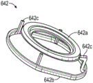
图5A和图5B提供根据一个实施例的生理监测装置的电池座的立体图。5A and 5B provide perspective views of a battery holder of a physiological monitoring device according to one embodiment.
图6A和图6B是根据一个实施例的生理监测装置的截面图。6A and 6B are cross-sectional views of a physiological monitoring device according to one embodiment.
图7是根据一个实施例的包括多个可选项目的生理监测装置的分解图。7 is an exploded view of a physiological monitoring device including a number of selectable items, according to one embodiment.
图8A和图8B是根据一个实施例的两个佩戴生理监测装置的人的立体图,示出装置如何弯曲以符合身体运动和位置。8A and 8B are perspective views of two people wearing a physiological monitoring device showing how the device bends to conform to body motion and position, according to one embodiment.
图9A、图9B、图9C、图9D、图9E和图9F示出根据一个实施例的用于将生理监测器应用于患者身体的各个步骤。9A, 9B, 9C, 9D, 9E, and 9F illustrate various steps for applying a physiological monitor to a patient's body, according to one embodiment.
图10A至图10C示意性地示出迹线层的替代示例。图10A示出迹线层的第一示例,而图10B描绘了图10A的插图A的特写。图10C示出迹线层的另一示例。10A-10C schematically illustrate alternative examples of trace layers. Figure 10A shows a first example of a trace layer, while Figure 10B depicts a close-up of inset A of Figure 10A. FIG. 10C shows another example of a trace layer.
图11A至图11I示意性地描绘了电池端子连接器的示例。图11A描绘了被构造为接触电池端子的电池端子连接器的内表面,并且图11B描绘了与图11A中描绘的表面相对的电池端子连接器的外表面。图11C描绘了被构造为接触电池端子的电池端子连接器的另一示例的内表面,并且图11D描绘了与图11C中描绘的表面相对的电池端子连接器的外表面。图11E示出电池端子连接器联接到的电池的轮廓图。图11F和图11G描绘了被构造为接触电池端子的电池端子连接器的另一示例的内表面。图11H和图11I描绘了与图11C中描绘的表面相对的电池端子连接器的外表面。11A to 11I schematically depict examples of battery terminal connectors. FIG. 11A depicts an interior surface of a battery terminal connector configured to contact a battery terminal, and FIG. 11B depicts an exterior surface of the battery terminal connector opposite the surface depicted in FIG. 11A . FIG. 11C depicts an interior surface of another example of a battery terminal connector configured to contact battery terminals, and FIG. 11D depicts an exterior surface of the battery terminal connector opposite the surface depicted in FIG. 11C . Figure 1 IE shows an outline view of a battery to which a battery terminal connector is coupled. 11F and 11G depict an interior surface of another example of a battery terminal connector configured to contact a battery terminal. Figures 11H and 11I depict the exterior surface of the battery terminal connector as opposed to the surface depicted in Figure 11C.
图12A至图12G示出上方壳体的另一示例的多视角图。图12A描绘了上方壳体的局部分解图。图12B示出柔性上框架的立体图。图12C示出柔性上框架的轮廓图。图12D示出柔性上框架的俯视图。图12E描绘了上方壳体的内表面的立体图。图12F描绘了上方壳体和下方壳体的轮廓图。图12G描绘了被构造用于密封壳体的顶部和底部的脊的轮廓图。12A to 12G show multiple perspective views of another example of the upper case. Figure 12A depicts a partially exploded view of the upper housing. Figure 12B shows a perspective view of the flexible upper frame. Figure 12C shows an outline view of the flexible upper frame. Figure 12D shows a top view of the flexible upper frame. Figure 12E depicts a perspective view of the inner surface of the upper housing. Figure 12F depicts a profile view of the upper and lower housings. Figure 12G depicts a profile view of ridges configured to seal the top and bottom of the housing.
图13A至图13B示出下方壳体的另一示例的多视角图。图13A描绘了下方壳体的立体图,而图13B描绘了下方壳体的轮廓图。13A-13B show multiple perspective views of another example of the lower housing. Figure 13A depicts a perspective view of the lower housing, while Figure 13B depicts an outline view of the lower housing.
图14A至图14B示出波形弹簧的示例的正交轮廓图。14A-14B show orthogonal contour views of examples of wave springs.
图15A至图15I示出生理监测装置的另一示例的多个视图。图15A描绘了生理监测装置的分解图。图15B描绘了生理监测装置的分解图。图15C描绘了移除上方壳体的壳体的轮廓图。图15D描绘了如图15C所示的额外移除了柔性上框架的壳体的轮廓图。图15E描绘了如图15D所示的额外移除了柔性下框架的壳体的轮廓图。图15F描绘了如图15E所示的额外移除了电池和弹簧的壳体的轮廓图。图15G描绘了如图15F所示的壳体的截面图,截面是在电路板120和弹簧接触垫片632之间截取的。图15H描绘了如图15G所示的额外移除了弹簧接触垫片的壳体的截面图。图15I描绘了如图15H所示的另外包括电路板的壳体的轮廓图。15A-15I show various views of another example of a physiological monitoring device. Figure 15A depicts an exploded view of a physiological monitoring device. Figure 15B depicts an exploded view of the physiological monitoring device. Figure 15C depicts a profile view of the housing with the upper housing removed. Figure 15D depicts an outline view of the housing shown in Figure 15C with the additional removal of the flexible upper frame. Figure 15E depicts a profile view of the housing shown in Figure 15D with the additional removal of the flexible lower frame. Figure 15F depicts an outline view of the case shown in Figure 15E with the battery and springs additionally removed. FIG. 15G depicts a cross-sectional view of the housing as shown in FIG. 15F , the section being taken between the
图16A至图16D示出生理监测装置的实施例的多个视图。图16A示出顶部立体图,图16B示出底部视图,图16C示出包括衬里的顶部立体图,图16D示出包括衬里的底部视图。16A-16D show various views of an embodiment of a physiological monitoring device. Figure 16A shows a top perspective view, Figure 16B shows a bottom view, Figure 16C shows a top perspective view including the liner, and Figure 16D shows a bottom view including the liner.
图17A和图17B示意性地示出打磨器的两个示例的截面图。图17A描绘了包括可压缩弹簧的打磨器。图17B描绘了包括可压缩泡沫的打磨器。17A and 17B schematically show cross-sectional views of two examples of sanders. Figure 17A depicts a sander including a compressible spring. Figure 17B depicts a sander comprising compressible foam.
图18示出心律推断服务的实施例的示意图。Figure 18 shows a schematic diagram of an embodiment of a heart rhythm inference service.
图19是用于从生理监测器中提取并传输数据特征的系统的实施例的示意图。19 is a schematic diagram of an embodiment of a system for extracting and transmitting data features from a physiological monitor.
具体实施方式Detailed ways
下面的描述涉及多个不同的实施例。然而,所描述的实施例可以以许多不同的方式实施和/或变化。例如,所描述的实施例可以在任何合适的装置、设备或系统中实施以监测多个生理参数中的任意一个。例如,以下讨论主要集中在长期贴片式心律监测装置上。在一个替代实施例中,生理监测装置可以例如用于脉搏血氧测定和阻塞性睡眠呼吸暂停的诊断。使用生理监测装置的方法也可能有所不同。在一些情况下,装置可以佩戴一周或更短时间,而在其他情况下,装置可以佩戴至少七天和/或超过七天,例如十四天到二十一天或甚至更长。The following description refers to a number of different embodiments. However, the described embodiments may be implemented and/or varied in many different ways. For example, the described embodiments may be implemented in any suitable device, device, or system to monitor any of a number of physiological parameters. For example, the following discussion focuses on long-term patch heart rhythm monitoring devices. In an alternative embodiment, the physiological monitoring device may be used, for example, for pulse oximetry and the diagnosis of obstructive sleep apnea. The method of using a physiological monitoring device may also vary. In some cases, the device may be worn for a week or less, while in other cases the device may be worn for at least seven days and/or more than seven days, such as fourteen to twenty-one days or even longer.
可能存在所描述的技术的许多其他替代实施例和应用。因此,仅出于示例目的提供以下描述。在整个说明书中,可以参考术语“共形”。本领域技术人员将理解的是,本文所用的术语“共形”是指表面或结构之间的关系,其中第一表面或结构适应第二表面或结构的轮廓。Many other alternative embodiments and applications of the described techniques are possible. Accordingly, the following description is provided for example purposes only. Throughout the specification, reference may be made to the term "conformal". Those skilled in the art will appreciate that the term "conformal" as used herein refers to a relationship between surfaces or structures in which a first surface or structure conforms to the contours of a second surface or structure.
由于不正常的心律或心律失常通常可由其他不太严重的原因引起,因此关键的挑战是确定这些症状中的任意一个何时是由心律失常引起的。通常,心律失常很少和/或偶发地发生,使得快速可靠的诊断变得困难。如上所述,目前,心律监测主要是通过使用固定在胸部的短期(少于1天)电极的装置,诸如Holter监测器来完成的。电线将电极连接到通常戴在腰带上的记录装置。电极需要每天更换而且电线很繁琐。这些装置的存储量和记录时间也有限。佩戴该装置会干扰患者的活动,并且通常会妨碍患者在接受监测时进行某些活动,例如洗澡。Since abnormal heart rhythms or arrhythmias can often be caused by other, less serious causes, a key challenge is to determine when any of these symptoms are caused by an arrhythmia. Often, arrhythmias occur infrequently and/or sporadically, making rapid and reliable diagnosis difficult. As mentioned above, at present, heart rhythm monitoring is mainly accomplished by devices using short-term (less than 1 day) electrodes fixed on the chest, such as Holter monitors. Wires connect the electrodes to a recording device, usually worn on a belt. Electrodes need to be replaced daily and the wires are cumbersome. These devices also have limited storage capacity and recording time. Wearing the device interferes with the patient's movement and often prevents the patient from performing certain activities while being monitored, such as bathing.
进一步,Holter监测器是可用性有限的固定设备,这种情况通常会导致供应受限和相应的检测延迟。这些限制严重阻碍了装置的诊断实用性、患者使用装置的依从性以及捕获所有重要信息的可能性。缺乏依从性和装置的缺点通常导致需要额外的装置、后续监测或其他检测来做出正确的诊断。Further, Holter monitors are stationary devices with limited availability, a situation that often results in supply constraints and corresponding detection delays. These limitations severely hamper the diagnostic utility of the device, patient compliance with device use, and the possibility to capture all important information. Lack of adherence and device shortcomings often result in the need for additional devices, follow-up monitoring, or other testing to make a correct diagnosis.
目前用于将症状与心律失常的发生相关联的包括诸如Holter监测器和心脏事件记录器心律监测装置的使用的方法通常不足以进行准确的诊断。事实上,Holter监测器已被证明在高达90%的情况不会导致诊断(DE Ward等人在1980年发表于《生物遥测患者监测(Biotelemetry Patient Monitoring)》第7卷标题为“24小时动态心电图监测的诊断价值评估(Assessment of the Diagnostic Value of 24-Hour AmbulatoryElectrocardiographic Monitoring)”)。Current methods for correlating symptoms with the occurrence of cardiac arrhythmias, including the use of cardiac rhythm monitoring devices such as Holter monitors and cardiac event recorders, are often insufficient for accurate diagnosis. In fact, the Holter monitor has been shown not to result in a diagnosis in up to 90% of cases (DE Ward et al. 1980 in Biotelemetry Patient Monitoring Volume 7 entitled "24-Hour Holter Assessment of the Diagnostic Value of 24-Hour Ambulatory Electrocardiographic Monitoring").
此外,实际获得心律监测装置并启动监测的医疗过程通常非常复杂。订购、跟踪、监控、检索和分析来自此类监控装置的数据通常涉及许多步骤。在大多数情况下,现今使用的心脏监测装置是由心脏病专家或心脏电生理学家(EP)而不是患者的初级保健医生(PCP)预定的。因为PCP通常是看到病人并确定病人的症状可能是由于心律失常引起的第一个医生,所以这至关重要。在患者看过PCP之后,PCP会为患者预约看心脏病专家或EP。该预约通常是与初次就诊PCP后的数周,这本身会导致潜在诊断的延迟,并增加心律失常发作而未确诊的可能性。当患者最终去看心脏病专家或EP时,通常会预定心律监测装置。监测期可以持续24至48小时(Holter监测器)或长达一个月(心脏事件监测器或移动遥测装置)。一旦完成监测,患者通常必须将装置返还诊所,这本身就很不方便。在监测公司或者医院或办公室现场的技术人员处理数据之后,最终会将报告发送给心脏病专家或EP进行分析。这个复杂的过程导致接受心律监测的患者比理想情况下接受心律监测的患者要少。Additionally, the medical process of actually obtaining a heart rhythm monitoring device and initiating monitoring is often very complex. Ordering, tracking, monitoring, retrieving and analyzing data from such monitoring devices typically involves many steps. In most cases, cardiac monitoring devices in use today are ordered by a cardiologist or cardiac electrophysiologist (EP) rather than the patient's primary care physician (PCP). This is critical because the PCP is often the first physician to see a patient and determine that a patient's symptoms may be due to an arrhythmia. After the patient has seen the PCP, the PCP will make an appointment for the patient to see a cardiologist or EP. This appointment is often weeks after the initial PCP visit, which in itself causes a delay in a potential diagnosis and increases the likelihood that an arrhythmia episode will go undiagnosed. When a patient finally sees a cardiologist or EP, a heart rhythm monitoring device is usually ordered. The monitoring period can last 24 to 48 hours (Holter monitor) or up to a month (cardiac event monitor or mobile telemetry device). Once monitoring is complete, patients often have to return the device to the clinic, which is inconvenient in itself. After the data is processed by the monitoring company or a technician on site at the hospital or office, the report is eventually sent to a cardiologist or EP for analysis. This complex process results in fewer patients receiving cardiac rhythm monitoring than ideally would.
为了解决心脏监测的这些问题中的一些,本申请的受让人开发了小型、长期、可穿戴、生理监测装置的多种实施例。该装置的一个实施例是
这些更小的、长期的、基于贴片的生理监测装置提供了优于现有技术装置的许多优点。同时,还需要进一步改进。最有意义的改进领域之一是向管理临床医生提供更及时的严重心律失常通知。这些初始实施例的特点是——因性能、依从性和成本的原因——装置仅在延长的佩戴时间段期间记录信息,并在记录完成之后进行分析和报告。因此,理想的改进是增加对收集到的心律信息进行实时或及时分析的能力。虽然目前存在具有这种及时报告能力的诊断监测器,但它们需要对系统的一个或多个电气组件定期进行充电或更换。这些行为会降低患者的依从性,进而降低诊断率。如此,关键的改进领域是开发一种可以在无需对电池进行充电或更换的情况下将长期记录与及时报告结合起来的生理监测器。These smaller, long-term, patch-based physiological monitoring devices offer many advantages over prior art devices. At the same time, further improvements are required. One of the most meaningful areas of improvement is more timely notification of severe arrhythmias to managing clinicians. A feature of these initial embodiments is that—for performance, compliance, and cost reasons—the device records information only during extended periods of wear, and analyzes and reports after the recording is complete. Therefore, a desirable improvement would be to add the ability to perform real-time or timely analysis of the collected heart rhythm information. While diagnostic monitors with this timely reporting capability currently exist, they require periodic recharging or replacement of one or more electrical components of the system. These behaviors can reduce patient compliance and, in turn, lower diagnostic yields. As such, a key area of improvement is the development of a physiological monitor that can combine long-term recording with timely reporting without the need for recharging or replacing batteries.
患者依从性和装置粘附性能是控制ECG记录的持续时间并因此控制诊断率的两个因素。可以通过改善患者的佩戴体验来提高依从性,佩戴体验受佩戴舒适度、装置外观以及装置对日常生活正常活动的妨碍程度的影响。鉴于较长的ECG记录可提供更高的诊断率和价值,因此需要改进装置粘附性和患者依从性。Patient compliance and device adhesion performance are two factors that control the duration of ECG recordings and thus the diagnostic yield. Adherence can be improved by improving the patient's wearing experience, which is influenced by wearing comfort, device appearance, and how much the device interferes with normal activities of daily living. Given that longer ECG recordings provide greater diagnostic yield and value, there is a need for improved device adhesion and patient compliance.
信号质量在整个佩戴期间都很重要,但在患者标记记录的地方可能更重要,该记录指示具有症状临床意义的区域。标记记录通过位于装置外表面的触发器最容易实现。然而,由于触发器可能是带有集成电极的皮肤接触平台的一部分,因此患者在摸索触发器时可能会引入明显的运动伪影。理想的装置改进是可以在添加最少运动伪影的情况下激活的症状触发器。Signal quality is important throughout the wear period, but may be even more important where the patient marks a recording indicating areas of clinical significance for symptoms. Marker recording is most easily accomplished with triggers located on the outer surface of the device. However, since the trigger may be part of a skin-contact platform with integrated electrodes, significant motion artifacts may be introduced when the patient fumbles for the trigger. An ideal device improvement would be a symptom trigger that can be activated with minimal addition of motion artifacts.
此外,期望该装置的制造简单且有成本效益,从而能够在制造时实现可扩展性以及由于过程中的可重复性而实现更高的质量。制造的简单性还可以易于拆卸,从而能够有效地回收印刷电路板,以便在另一个装置中进行质量控制的再利用。有效地再利用这个昂贵的组件对于降低诊断监测器的成本十分重要。Furthermore, the device is desired to be simple and cost-effective to manufacture, enabling scalability in manufacture and higher quality due to repeatability in the process. The simplicity of manufacture also allows for easy disassembly, enabling efficient recycling of printed circuit boards for quality controlled reuse in another installation. Efficient reuse of this expensive component is important to reduce the cost of diagnostic monitors.
仍然存在持续时间更长且成本更低的解决方案可能是对心脏动态监测选项组合的有价值的补充的临床情景。这些需求的潜在解决方案的灵感可以从连续心率感测功能中找到,这种功能越来越多地被纳入各种消费者健康和健身产品,包括智能手表和可穿戴健身手环。尽管连续心率数据可以用于为使用者提供关于其总体健康水平的信息,但使用此数据提供与他们的健康和保健相关的有意义的信息更具挑战性和价值。例如,从连续的心率数据中检测潜在心律失常的能力将使包含心率感测功能的消费装置成为用于早期检测心脏异常的潜在筛查工具。这种方法在为高危人群,例如有心房颤动风险的心力衰竭患者提供长期、划算的筛查方法方面可能具有临床价值。可选地,这种监测方法可能有助于治疗药物剂量的长期滴定以在减少副作用的同时确保疗效,例如在阵发性心房颤动的治疗中。除了心律失常检测之外,对心率信息的适当分析还可以深入了解睡眠和压力应用。There remain clinical scenarios where a longer-lasting and lower-cost solution might be a valuable addition to the portfolio of ambulatory cardiac monitoring options. Inspiration for potential solutions to these needs can be found in the continuous heart rate sensing capability that is increasingly being incorporated into a variety of consumer health and fitness products, including smart watches and wearable fitness bands. While continuous heart rate data can be used to provide users with information about their overall fitness level, using this data to provide meaningful information related to their health and wellness is more challenging and valuable. For example, the ability to detect potential cardiac arrhythmias from continuous heart rate data would make consumer devices incorporating heart rate sensing a potential screening tool for early detection of cardiac abnormalities. This approach may have clinical value in providing long-term, cost-effective screening for high-risk populations, such as heart failure patients at risk for atrial fibrillation. Alternatively, such monitoring methods may facilitate long-term titration of therapeutic drug doses to ensure efficacy while reducing side effects, such as in the treatment of paroxysmal atrial fibrillation. In addition to arrhythmia detection, proper analysis of heart rate information can provide insight into sleep and stress applications.
特别是在监测期间在可以提供关于观察到的心律失常的发生和持续时间的及时信息时,使用诸如贴片的生理装置进行长期动态监测具有多种临床应用。就流行率而言,尤其是在人口老龄化的推动下,有效检测心房颤动(AF)仍然是最重要的监测需求。这种需求不仅对于出现症状的患者是显而易见的,而且考虑到与这种心律失常相关的中风风险增加,对于由于高龄、存在心脏病等慢性疾病、甚至做过外科手术中的一个或多个因素而处于风险中的个体的无症状AF的更广泛的、基于人群的监测也是显而易见的。对于后一组,围手术期的和手术后的监测不仅对于针对心律失常预防的手术(例如,均用于治疗AF的MAZE消融手术或心内膜和心外膜混合手术)而且对于涉及麻醉的普通手术都具有临床价值。对于某些应用,心房颤动动态监测的目标有时会集中于一个简单的二元问题即AF是否确实在给定时间段内发生。例如,在消融手术后监测患者通常是为了确认成功,成功通常定义为完全没有AF发生。同样,监测中风的后患者将主要涉及评估心房颤动的存在。Long-term ambulatory monitoring using physiological devices such as patches has a variety of clinical applications, especially when it can provide timely information on the onset and duration of observed arrhythmias during monitoring. Effective detection of atrial fibrillation (AF) remains the most important surveillance need in terms of prevalence, especially driven by an aging population. Not only is this need evident in symptomatic patients, but given the increased risk of stroke associated with this arrhythmia, it may be difficult to respond to one or more of these factors due to advanced age, the presence of chronic medical conditions such as heart disease, or even previous surgical procedures. More extensive, population-based surveillance of asymptomatic AF in at-risk individuals is also evident. For the latter group, perioperative and postoperative monitoring is important not only for procedures aimed at arrhythmia prevention (for example, MAZE ablation procedures or mixed endocardial and epicardial procedures, both for AF) but also for procedures involving anesthesia. General surgery has clinical value. For some applications, the goal of ambulatory monitoring of atrial fibrillation is sometimes focused on a simple binary question of whether AF actually occurred within a given time period. For example, patients are often monitored after ablation procedures to confirm success, which is usually defined as the complete absence of AF. Likewise, monitoring post-stroke patients will primarily involve assessing for the presence of atrial fibrillation.
然而,即使在那些情况下,如果发生AF,评估其他方面以更好地描述发生的特征可能具有临床意义,发生的特征诸如日常负担(每天AF时间的百分比)和发作持续时间(例如,表现为发作持续时间的直方图,或表现为超过例如六分钟的指定限制的发作百分比),无论是绝对值还是与先前基准(例如,从基线、术前监测结果)的比较。实际上,测量日常AF负担、评估AF发作持续时间、回顾睡眠期间和清醒期间的AF发生情况以及根据患者身体运动的程度评估AF的存在,对包括评估基于药物对这种心律失常的治疗的有效性的各种临床情况都很重要。However, even in those cases, if AF occurs, it may be of clinical interest to assess other aspects to better characterize the occurrence, such as daily burden (percentage of AF time per day) and duration of episodes (e.g., manifested as Histogram of seizure duration, or expressed as the percentage of seizures exceeding a specified limit, eg, six minutes), either in absolute value or in comparison to previous baselines (eg, from baseline, preoperative monitoring results). Indeed, measuring the daily AF burden, assessing the duration of AF episodes, reviewing the occurrence of AF during sleep and during waking hours, and assessing the presence of AF according to the degree of patient physical activity are useful, including in assessing the effectiveness of drug-based treatments for this arrhythmia. Sexuality is important in a variety of clinical situations.
在监测期间及时提供该信息可以允许治疗医师例如通过调整新型口服抗凝药物(NOAC)的剂量和频率反复滴定治疗直到治疗被优化。这种治疗模式的另一个示例是通知患者无症状AF——通过装置直接通过声音或振动的警报,通过来自连接到装置的应用程序的通知,或经由来自治疗临床医生的电话、电子邮件或短信的沟通——以及时应用用于AF治疗的“顿服(pill in the pocket)”。Providing this information in a timely manner during monitoring may allow the treating physician to repeatedly titrate therapy until therapy is optimized, for example by adjusting the dose and frequency of a novel oral anticoagulant (NOAC). Another example of this treatment modality is notifying a patient of asymptomatic AF - directly through the device via an audible or vibrating alert, via a notification from an app connected to the device, or via a phone call, email or text message from the treating clinician communication - and timely application of the "pill in the pocket" for AF treatment.
及时治疗和/或干预的主题在观察到临床显著心律失常,例如无症状的二度和完全性心肌梗死、延长的暂停、高速率室上性心动过速、延长的室性心动过速以及心室颤动的情况下当然是显而易见的。例如,延长的暂停或完全性心肌梗死导致晕厥的临床情况是特别重要情况,在这种情况下及时可靠的监测方法的可用性可以减少甚至消除对高危患者进行住院监测的需要。该主题还可以扩展到更细微的形态变化,例如,QT对药物的反应延长,这已被证明对心脏安全有重要影响。及时意识到这种延长可能会引起,例如提前终止评估药物安全性和有效性的临床研究,或者调整剂量或频率作为消除观察到的延长的手段。Subject of prompt treatment and/or intervention in case of observation of clinically significant arrhythmias such as asymptomatic second degree and complete myocardial infarction, prolonged pauses, high rate supraventricular tachycardia, prolonged ventricular tachycardia, and ventricular The case of flutter is of course obvious. For example, clinical situations in which prolonged pauses or complete myocardial infarctions lead to syncope are particularly important situations where the availability of timely and reliable monitoring methods can reduce or even eliminate the need for inpatient monitoring in high-risk patients. The topic can also be extended to more subtle morphological changes, for example, prolonged QT response to drugs, which have been shown to have important implications for cardiac safety. Timely awareness of such prolongation may cause, for example, premature termination of clinical studies evaluating the drug's safety and efficacy, or adjustment of dose or frequency as a means of eliminating the observed prolongation.
生理监测装置Physiological Monitoring Device
参照图1A和图1B,提供了生理监测装置100的一个实施例的立体图和分解轮廓图。如图1A所示,生理监测装置100可以包括与防水壳体115联接的柔性主体110。如本领域技术人员将理解的是,本文和整个说明书中描述的壳体可以由刚性或柔性材料构造,从而使壳体,例如是刚性的,以抵抗变形,或者例如,是柔性的,以在力的作用下弯曲和/或变形。柔性主体110(可称为“柔性基底”或“柔性构造”)通常包括从壳体115横向延伸的两个翼130、131和两个柔性电极迹线311、312,电极迹线中的每一个嵌入翼130、131中的一个。每个电极迹线311、312在柔性主体110的底表面上与柔性电极(在图1A中不可见)联接。电极被构造为感测来自附接有监测装置100的患者的心律信号。然后电极迹线311、312将那些信号传输到壳体115中容纳的电子器件(图1A中不可见)。壳体115通常还包含电源,诸如一个或多个电池。Referring to FIGS. 1A and 1B , perspective and exploded outline views of one embodiment of a
包括柔性电极和电极迹线311、312的高度柔性主体110与壳体115的组合可以提供许多优势。关键优势是高保真信号捕获。高度共形柔性翼130、131,电极和迹线311、312限制外部能量传输到电极-皮肤界面(electrode-skin interface)。例如,如果壳体115产生运动,则共形粘附到皮肤的系统会限制该运动对监测信号的影响程度。柔性电极迹线311、312通常可以帮助提供与受试者皮肤的共形接触并且可以帮助防止电极350(电极350在图1中不可见,但在下面描述的图6A中可见)从皮肤上剥离或抬起,从而通过将向电极350传递的应力最小化来提供强大的运动伪影抑制和更好的信号质量。此外,柔性主体110包括便于患者在不移除的情况下舒适地佩戴装置100十四(14)天或更长时间的构造和各种特征。在本文所述的实施例中通常不粘附在患者身上的壳体115包括有助于装置100舒适度的特征。铰接部132是柔性主体110的相对较薄、甚至更柔性的部分。它们允许柔性主体110在与壳体115连接的区域自由弯曲。这种柔性提高了舒适度,因为在患者移动时,壳体115可以自由地抬离患者的皮肤,所以这种柔性提高了舒适度。电极迹线311、312也非常细且柔韧,以允许患者在不造成信号失真的情况下移动。The combination of a highly
现在参照图1B,生理监测装置100的部分分解图更详细地示出构成壳体115并包含在壳体115中的构成部件。在本实施例中,壳体115包括可拆卸地与下方壳体构件145联接的上方壳体构件140。夹在上方壳体构件140和下方壳体构件145之间的是上垫圈370和下垫圈360(在图1B上不可见但在上垫圈370的正下方)。垫圈370、360有助于壳体构件和/或主体115在组装好时防水。监测装置100的多个组件可以容纳在上方壳体构件140和下方壳体构件145之间。例如,在一个实施例中,壳体115可以包含柔性主体110的一部分、印刷电路板组件(PCBA)120、电池座150和两个电池160。印刷电路板组件120位于壳体115内以接触电极迹线311、312和电池160。在多种实施例中,一个或多个附加组件可以包含在壳体115内或附接到壳体115。下面参照附加附图进一步描述这些可选组件中的一些。Referring now to FIG. 1B , a partially exploded view of
根据多种替代实施例,电池座150可以容纳两个电池(如所示实施例中)、一个电池或多于两个电池。在其他替代实施例中,可以使用其他电源。在所示的实施例中,电池座150包括用于将电池160容纳在电池座150中的多个保持片和/或突耳153。此外,电池座150包括多个支脚和/或突耳152以使电池160与PCBA 120表面形成恰当的间隔并确保与弹簧触片和/或触点235和236适当接触。在本实施例中使用弹簧触片235和236而不是将电池160焊接到PCBA120。尽管在替代实施例中可以使用焊接,但是弹簧触片235和236的一个优点是它们允许电池160在不损坏那些组件中的任何一个的情况下从PCBA120和电池座150移除,从而允许两者多次重复使用。消除焊接连接还简化和加速了监测装置100的组装和拆卸。According to various alternative embodiments,
在一些实施例中,上方壳体构件140可以充当患者事件触发器。当患者佩戴用于心律监测的生理监测装置100时,患者能够向装置100登记(例如,登录到设备的存储器中)患者感知的任何心脏事件通常是有利的。例如,如果患者感觉到他/她认为是心律失常发作的情况,则患者可以以某种方式触发装置100并因此提供感知的事件的记录。在一些实施例中,患者感知的事件的触发可以启动与触发的事件相关联的数据的传输。在一些实施例中,感知的事件的触发可以简单地用触发事件的位置来标记连续的记录。在一些实施例中,相关数据的传输以及连续记录的标记都可能发生。在稍后的某个时间,可以将患者在感知事件期间记录的症状与装置100记录的患者实际心律进行比较,这可能有助于确定患者感知的事件是否与实际心脏事件相关。然而,当前可用的可穿戴心律监测装置中患者事件触发器的一个问题是,可能难以发现和/或激活小触发,特别是由于监测装置通常佩戴在衣服里面。此外,按下触发按钮可能会影响装置上的电子器件和/或电极,使得那一刻记录的心律信号仅通过患者触发引起的装置运动而改变。例如,即使实际没有发生心律失常事件,按下触发器可能会震动一个或两个电极也使得那一刻记录的心律信号看起来像心律失常。此外,触发器可能会被无意中激活,例如在睡在或躺在监测装置上时。In some embodiments,
然而,在图1A和图1B所示的实施例中,壳体115的刚性足够,而柔性主体110的柔性足够,使得患者施加到壳体115的运动可能很少或永远不会导致电极检测到异常信号。在本实施例中,上方壳体构件140的中央部略微凹入,并且当佩戴装置100的患者按压时,该中央部略微下压以触发PCBA 120上的触发器输入。因为壳体115的整个上表面充当患者事件触发器,结合它略微凹入的事实,所以即使触发器在衣服下面,患者也通常很容易找到并按下触发器。此外,按钮的凹形特性使其可以凹陷,从而防止其被意外激活。因此,本实施例可以减轻当前可用的心律监测器上的患者事件触发器所遇到的一些问题。下面将更详细地描述图1A和图1B中所示特征的这些和其他方面。However, in the embodiment shown in FIGS. 1A and 1B , the
现在参照图2A和图2B中的实施例,印刷电路板组件120(或PCBA)可以包括顶表面220、底表面230、患者触发器输入210和弹簧触点235、236和237。印刷电路板组件120可以用于使用导电路径、迹线或电极迹线311、312来机械支撑和电连接电子组件。此外,由于PCBA120的敏感特性以及与刚性主体115机械连接的要求,PCBA 120的刚性足够以防止可能将噪声或伪影引入ECG信号的非期望的偏差是有益的。在患者触发器激活期间力尤其可能通过刚性主体115传输到PCBA 120。在一些实施例中,确保PCBA刚度的一种方式是确保PCBA的厚度相对高于特定值。例如,至少约0.08cm的厚度是可取的,并且更优选地,至少约0.17cm的厚度是可取的。在本申请中,PCBA120也可称为印刷电路板(PCB)、印刷线路板(PWB)、蚀刻线路板或印刷电路组件(PCA),或由它们替代。在一些实施例中,除了PCBA120之外,可以使用绕线或点对点构造,或者可以使用绕线或点对点构造来代替PCBA120。PCBA 120可以包括模拟电路和数字电路。Referring now to the embodiment in FIGS. 2A and 2B , printed circuit board assembly 120 (or PCBA) may include
患者触发器输入210可以被构造为将信号从患者触发器,诸如上述上方壳体构件140中继到PCBA 120。例如,患者触发器输入210可以是响应来自患者触发器(例如,上方壳体部分140的上表面)的压力的PCB开关或按钮。在多种实施例中,患者触发器输端入210可以是表面安装开关、触觉开关、LED照明触觉开关等。在一些实施例中,患者触发器输入210还可以激活指示器,诸如LED。某些实施例可能涉及远程触发器,诸如在单独的装置上或作为智能手机应用程序。
在使用诸如本文中描述的装置100的小型双电极生理监测装置从人类或动物受试者收集心律信号时,一个重要的挑战是在试图区分伪影和临床显著信号时,仅具有两个电极有时可以提供的视角有限。例如,当一名左撇子患者在左胸佩戴小型双电极生理监测装置时刷牙时,刷牙可能经常会引入运动伪影,导致记录的信号看起来非常类似于室性心动过速,这是一种严重的心律失常。添加额外的导线(因此,载体(vector))是减轻这种担忧的传统方法,但这通常是通过添加粘附到患者胸部的不同位置的额外的电线来完成的,诸如通过Holter监测器。这种方法不适用于诸如生理监测装置100的小型可穿戴长期监测器。When collecting heart rhythm signals from human or animal subjects using a small two-electrode physiological monitoring device such as the
解决上述问题的另一种方法是提供一个或多个附加数据通道以帮助辨别信号。在一些实施例中,例如,装置100可以包括用于检测贴片运动的数据通道。在某些实施例中,加速度计或其他合适的装置可以通过简单地分析单个轴测量值或者所有三个轴的组合的幅度变化来提供贴片运动。加速度计可以以足够的采样率记录装置运动,以允许对其频谱与记录的ECG信号的频谱进行算法比较。如果运动和记录的信号匹配,则很明显该时间段内的装置记录不是来自临床(例如,心脏)来源,因此可以自信地将该信号的这部分标记为伪影。该技术在上述刷牙运动示例中可能特别有用,其中快速运动频率和高振幅伪影分别类似于可能危及生命的心律失常(如室性心动过速)的心率和形态。本节和说明书其他地方描述的其他合适的装置也可以用于提供运动信息。Another way to solve the above problem is to provide one or more additional data channels to help distinguish signals. In some embodiments, for example,
在一些实施例中,使用三个轴的值进行这样的分析将消除由于位置偏移而不是活动变化引起的值的任何突然变化。在其他实施例中,使用诸如沿着身体的纵轴的特定测量轴来关注由与步行或跑步相关联的向上和向下运动引入的特定类型的伪影可能有一些优势。类似地,结合加速度计使用陀螺仪可以进一步确定所经历的运动的性质。虽然单独使用加速度计可以充分分析全身运动,但诸如由于手臂运动引起的旋转运动之类的感兴趣的特定运动非常复杂,单独使用加速度计可能无法辨别。In some embodiments, performing such an analysis using the values of the three axes will eliminate any sudden changes in values due to position shifts rather than activity changes. In other embodiments, there may be some advantage in using a specific measurement axis, such as along the longitudinal axis of the body, to focus on specific types of artifacts introduced by up and down motions associated with walking or running. Similarly, using a gyroscope in conjunction with an accelerometer can further determine the nature of the motion being experienced. While full-body motion can be adequately analyzed with an accelerometer alone, specific motions of interest, such as rotational motion due to arm motion, are complex and may not be discernible with an accelerometer alone.
除了检测运动伪影之外,调谐到人体身体活动的动态范围的加速度计可以提供患者在记录期间的活动水平,这也可以提高算法真实心律失常检测的准确性。考虑到装置100的单导线限制,除了诸如室上性心动过速之类的速率变化之外还需要观察不太显著的波(例如P波)的心律失常对计算机化算法以及受过训练的人眼都带来了挑战。这种特殊的心律失常还具有突然发作的特点,如果在心率增加的同时检测到患者活动水平突然激增,则可以更有把握地将其与非病理性窦性心动过速区分开来。广泛地说,向临床专业人员提供活动信息可能有助于他们区分运动性心律失常与非运动性心律失常。与运动伪影检测一样,针对特定方向优化的单轴加速度计测量可能有助于更具体地确定活动类型,诸如步行或跑步。这些附加信息可能有助于更具体地解释症状,从而影响后续的治疗过程。In addition to detecting motion artifacts, an accelerometer tuned to the dynamic range of human body activity can provide the patient's activity level during the recording, which can also improve the accuracy of the algorithm's true arrhythmia detection. Given the single-lead limitation of the
在某些实施例中,具有3个轴的加速度计可以赋予的优势超出运动幅度可以提供的优势。当受试者没有快速移动时,3维加速度计读数可能接近PCBA120的倾斜度,因此身体相对于其原始方向定向。可以假设原始身体方向为直立或仰卧位,这是将装置适当定位和应用到身体所需要的。该信息可能有助于排除某些表现为逐拍形态变化的心脏状况,诸如观察到周期性的振幅变化的心脏交替,通常出现在心力衰竭病例中。在身体位置发生变化时,由于心脏位置相对于电极载体的变化,例如从直立到懒散位置,在健康受试者中可以观察到类似的逐拍形态变化。通过设计,单通道装置100没有备用ECG通道来容易地排除潜在的形态学病理变化,然而,与身体方向变化的相关性将有助于解释这些正常变化和避免由于错误诊断而导致的不必要治疗。In some embodiments, having an accelerometer with 3 axes may confer advantages beyond that provided by the range of motion. When the subject is not moving rapidly, the 3D accelerometer reading may be close to the inclination of the PCBA120, so the body is oriented relative to its original orientation. The original body orientation can be assumed to be an upright or supine position, which is required for proper positioning and application of the device to the body. This information may help to rule out certain cardiac conditions that show beat-to-beat morphology changes, such as cardiac alternation in which periodic amplitude changes are observed, often seen in cases of heart failure. Similar beat-to-beat morphological changes can be observed in healthy subjects upon changes in body position due to changes in the position of the heart relative to the electrode carrier, such as from an upright to a slouched position. By design, the single-
在其他实施例中,加速度计也可以基于身体方向和运动用作睡眠指示器。在呈现临床事件(例如,停顿)时,能够以清楚地区分睡眠期间发生的事件与清醒时发生的事件的方式呈现信息对诊断是有帮助的。事实上,诸如用于ECG衍生的呼吸率的某些算法只有在患者处于相对静止状态时跑步才有意义,因此可以观察到由于呼吸导致的胸部运动引入的细微信号调制。呼吸率信息作为检测某些患者群体睡眠呼吸暂停所需的一种信息渠道十分有用。In other embodiments, accelerometers may also be used as sleep indicators based on body orientation and motion. When presenting a clinical event (eg, a pause), it is helpful for diagnosis to be able to present the information in a manner that clearly distinguishes what occurred during sleep from what occurred while awake. In fact, some algorithms such as those used for ECG-derived respiration rate only make sense when running while the patient is relatively still, so subtle signal modulations introduced by chest motion due to respiration can be observed. Respiration rate information is useful as a source of information needed to detect sleep apnea in certain patient populations.
在某些实施例中,加速度计也可以用于检测自由落体,例如晕厥。通过加速计,装置100能够在不依赖患者触发器的情况下标记昏厥(晕厥)和其他自由落体事件。在一些实施例中,这样的自由落体事件触发器可以启动关联数据的传输。为了能及时检测此类关键事件,但考虑到诸如装置100的小型可穿戴装置的电池和内存限制,加速度计读数的获取可以在瞬间完成,其中只有诸如潜在自由落体之类的感兴趣的信息以高采样率写入存储器。扩展该事件触发器概念是为了使用装置100上的特定敲击动作作为患者触发器而不是先前描述的按钮,或将装置100上的特定敲击动作与先前描述的按钮结合使用。使用和检测多种类型的敲击序列可以准确地了解患者的确切感受然后提供更好地解决方案,而不是依赖患者事后在触发日志中手动记录他们的症状和持续时间。这种增加的解决方案的示例是通过连续敲击的次数来指示症状的严重性。In some embodiments, accelerometers may also be used to detect free fall, such as fainting. Through the accelerometer,
可选地,在其他实施例中,光学传感器可以用于区分装置运动和患者身体运动。进一步地,在另外的实施例中,装置可能不需要按钮或触发器。在更多的实施例中,也可以使用在本节或说明书其他地方描述的合适的装置。Optionally, in other embodiments optical sensors may be used to distinguish device motion from patient body motion. Further, in other embodiments, the device may not require buttons or triggers. In further embodiments, suitable devices described in this section or elsewhere in the specification may also be used.
可以添加到生理监测装置100的另一个可选数据通道是用于检测装置100的柔性和/或弯曲度的通道。在多种实施例中,例如,装置100可以包括用于检测装置100本身的运动伪影进而帮助区分运动伪影和心律数据的应变计、压电传感器或光学传感器。装置100的又一可选数据通道可以是用于检测心率的通道。例如,脉搏血氧仪、麦克风或听诊器可以提供心率信息。冗余心率数据可能有助于区分ECG信号和伪影。这在诸如室上性心动过速的心律失常被伪影打断的情况下特别有用,并且必须决定该发作实际上是多个较短的发作还是一个持续发作。可以包括另一个数据通道以检测环境电噪声。例如,装置100可以包括用于接收电磁干扰的天线。电磁干扰的检测可以促进电噪声与真实ECG信号的区分。可以存储上述数据通道中的任意一个以支持未来的噪声辨别或应用于实时地立刻确定临床有效性。Another optional data channel that may be added to the
现在参照图3A和图3B的实施例,更详细地示出柔性主体110。如图3A中所示,柔性主体110可以包括翼130、131,围绕每个翼130、131的至少一部分的薄边界133(或“边沿”或“边缘”),电极迹线311、312和每个翼130、131与壳体115的接合处或附近的铰接部132(或“肩部”)。图3A中还示出上垫圈370,在该描述中它不被认为是柔性主体110的一部分,但它有助于将柔性主体110附接到壳体115。Referring now to the embodiment of FIGS. 3A and 3B , the
铰接部132是柔性主体110的相对较薄、甚至更柔性的部分。它们允许柔性主体110在与壳体115连接的区域自由弯曲。因为在患者移动时,壳体115可以自由地抬离患者的皮肤,所以这种柔性提高了舒适度。电极迹线311、312也非常细且具有柔性,以允许患者在不造成信号失真的情况下移动。边界133是柔性主体110的部分,它比直接相邻的部分更薄,并且提供从柔性主体110到患者皮肤的平滑过渡,从而防止边缘抬升和污垢或碎屑渗透到柔性主体110下面。The
如图3B中更详细地示出的,柔性主体110可以包括多个层。如前所述,在一些实施例中,出于描述的目的,上垫圈370和下垫圈360不被认为是柔性主体110的一部分,而是为了描述的完整性而示出的。然而,这种区别只是为了便于描述,不应被解释为限制所描述的实施例的范围。柔性主体110可以包括顶部基底层300、底部基底层330、粘附层340和柔性电极350。顶部基底层300和底部基底层330可以由任何合适的柔性材料制成,诸如一种或多种柔性聚合物。合适的柔性聚合物可以包括但不限于聚氨酯、聚乙烯、聚酯、聚丙烯、尼龙、聚四氟乙烯和碳浸渍乙烯基。可以基于期望的特性来选择基底层300、330的材料。例如,可以根据柔韧性、弹性、耐久性、透气性、水分蒸发、粘附性等来选择基底层300、330的材料。在一个实施例中,例如,顶部基底层300可以由聚氨酯制成,而底部基底层330可以由聚乙烯或聚酯制成。在其他实施例中,基底层300、330可以由相同的材料制成。在又一实施例中,基底层330可以在粘附层340上方的区域中包含多个穿孔以提供更好的透气性和水分蒸发。在多种实施例中,患者可以连续佩戴生理监测装置100多达14至21天或更长时间,在佩戴期间无需移除并且在淋浴、锻炼等期间也佩戴装置100。因此,所使用的材料以及基底层300、330的厚度和构造影响生理监测装置100的功能。在一些实施例中,基底层300、330的材料充当静电放电(ESD)屏障以防止电弧放电。As shown in more detail in FIG. 3B ,
通常,顶部基底层300和底部基底层330经由放置在一个层或两个层300、330上的粘附剂彼此附接。例如,基底层300、330之间的粘附剂或结合物质可以是丙烯酸基、橡胶基或硅基粘附剂。在其他替代实施例中,柔性主体110可以包括多于两层的柔性材料。Typically, the top substrate layer 300 and the bottom substrate layer 330 are attached to each other via an adhesive placed on one or both layers 300 , 330 . For example, the adhesive or bonding substance between the base layers 300, 330 may be an acrylic-based, rubber-based or silicon-based adhesive. In other alternative embodiments, the
除了材料的选择之外,可以基于柔性主体110的期望特性来选择基底层300、330的尺寸,诸如厚度、长度和宽度。例如,在多种实施例中,可以选择基底层300、330的厚度以赋予柔性主体110约0.1mm至约1.0mm的总厚度。根据多种实施例,柔性主体110还可以具有约7cm至15cm的长度和约3cm至约6cm之间的宽度。通常,柔性主体110将具有足以在电极350之间提供必要的间隔量的长度。例如,在一个实施例中,一个电极350的中心到另一个电极350的中心的距离应该至少约为6.0cm,更优选地至少约为8.5cm。该间隔距离可能会根据应用有所不同。在一些实施例中,基底层300、330可以都具有相同的厚度。可选地,两个基底层300、330可具有不同的厚度。In addition to the choice of material, the dimensions of the base layers 300, 330, such as thickness, length and width, may be selected based on desired properties of the
如上所述,铰接部132允许刚性主体115抬离患者而柔性主体110保持粘附在皮肤上。铰接部132的功能对于允许装置在可能拉伸和压缩皮肤的各种活动中保持粘附在患者身上是至关重要的。此外,铰接部132允许显著改善佩戴该装置时的舒适度。通常,铰接部132会足够宽以供刚性主体115在不对柔性主体110产生过大的剥离力的情况下充分提升。例如,在多种实施例中,铰接部132的宽度应至少约为0.25cm并且更优选地至少约为0.75cm。As noted above, hinge 132 allows
此外,可以基于期望的特性来选择柔性主体110的形状或覆盖区。如图3A所示,翼130、131和边界133可以为使柔性主体110整体为“花生”形状的圆形边缘。然而,翼130、131可以形成为任意数量的不同形状,诸如矩形、椭圆形、环形或条形。在图3A和图3B所示的实施例中,顶部基底层300的覆盖区大于底部基底层330的覆盖区,其中顶部基底层300延伸形成边界133。因此,边界133由与顶层300相同的聚氨酯材料制成。因为它们仅包括顶层300,所以边界133比每个翼130、131的相邻部分更薄。更薄、高度有可塑性的边缘和/或边界133可能会增强生理监测装置100对患者的粘附,因为它提供了从翼130、131的相邻、稍厚部分到患者皮肤的过渡,因此有助于防止装置100的边缘从皮肤上剥离。边界133还可以帮助防止污垢和其他碎屑聚集在柔性主体110下方,这可以帮助促进对皮肤的粘附并且还增强了装置100的美感。在可选实施例中,基底层300、330的覆盖区可以相同,从而不存在边界133。Furthermore, the shape or footprint of the
虽然图1A至图3B的所示实施例仅包括沿大致相反的方向(例如,彼此成180度角)从壳体115延伸的两个翼130、131,但在替代实施例中可以有其他配置。例如,在一些实施例中,可以沿彼此不对称的方向布置翼130、131和/或可以包括一个或多个附加翼。只要提供足够的电极间隔以允许生理信号监测,并且只要翼130、131被构造为提供对皮肤的延伸附着,可以使用任何合适的配置和任何数量的翼130、131和电极迹线311、312。上述实施例已证明有利于粘附、患者舒适度和所收集的心律数据的准确性,但在替代实施例中,可以实施替代配置。While the illustrated embodiment of FIGS. 1A-3B includes only two
粘附层340是施加到底部基底层330的底表面的两个部分的粘附剂,每个部分对应于翼130、131中的一个。粘附层340因此不沿着底部基底层330的安装有壳体115的部分延伸。粘附层340可以由任何合适的粘附剂制成,尽管已经发现某些粘附剂有利于提供对患者皮肤的相对舒适并且没有皮肤刺激的长期粘附。例如,在一个实施例中,粘附层340是水胶体粘附剂。在另一实施例中,粘附层340由水胶体粘附剂构成,该水胶体粘附剂包含在排汗过程中从皮肤吸收水分的天然衍生的或合成的吸收材料。The
现在参照图3B,粘附层340的两个部分中的每一个包括孔,电极350中的一个装配到该孔中。电极350由柔性材料制成以进一步提供柔性主体110的整体贴合性。在一个实施例中,例如,柔性电极350可以由水凝胶电极350制成。电极350通常提供与皮肤的共形、无刺激的接触以提供与皮肤的增强的电连接并减少运动伪影。在一些实施例中,可以将水凝胶电极350冲压到粘附层340中,从而形成孔并通过水凝胶电极350填充它们。在一个替代实施例中,电极350和粘附剂340可以用导电材料制成的粘附层代替,使得每个翼130、131下侧上的整个粘附层用作电极。这种粘附层可以包括混合粘附/导电物质或与导电元素或颗粒混合的粘附剂物质。例如,在一个实施例中,这样的粘附层可以是水凝胶和水胶体粘附剂的混合物。图1A的壳体115还保护壳体115中包含的电子器件和电源,增强患者提供与感知到的心脏事件相关的输入的能力并允许简单的制造和重复使用壳体115的至少一些所含物。下文更详细地描述生理监测装置100的这些和其他特征。Referring now to FIG. 3B , each of the two parts of the
如上所述,在一些实施例中,粘附层340可以覆盖下基底层330的下侧的一部分,使得柔性主体110底侧的至少一部分不包括粘附层340。如图3A所示,铰合132可以作为每个翼130、131的未施加粘附层340的部分形成在柔性主体110中。铰接部132通常位于柔性主体110与壳体115的接合处或附近,从而为装置100提供的弯曲以适应患者的移动。在一些实施例中,铰接部132的宽度可以小于翼130、131的相邻部分的宽度,从而使装置100具有上述“花生”形状。如图8所示,当受试者移动时,装置100随着患者移动而弯曲。装置弯曲可能很严重并且在长期监测期间可能会发生很多次。铰接部132可以允许与受试者的动态贴合,而壳体115的刚性可以允许壳体115在装置弯曲期间从患者的皮肤弹出,从而防止装置100在其边缘处从皮肤上剥离。As noted above, in some embodiments, the
柔性主体110进一步包括夹在上基底层300和下基底层330之间的两个电极迹线311、312。每个电极迹线311、312可以包括电极接口部310和心电图电路接口部313。如图3C和图3D的实施例中所示,ECG电路接口部313与弹簧触片237物理接触并且在组装好装置100或放大装置部101时提供与PCBA120的电通信。电极接口部310接触水凝胶电极350。因此,电极迹线311、312将心律信号(和/或多种实施例中的其他生理数据)从电极350传输到PCBA120。The
电极迹线311、312的材料和厚度对于提供柔韧性、耐久性和信号传输的期望组合十分重要的。例如,在一个实施例中,电极迹线311、312可以包括银(Ag)和氯化银(AgCl)的组合。银和氯化银可以分层设置。例如,电极迹线311、312的一个实施例可以包括顶部的银层、中间的碳浸渍乙烯基层和底部(面向患者)的氯化银层。在另一实施例中,电极迹线311、312的顶层和底层都可以由氯化银制成。在一个实施例中,顶层和底层可以分别以银墨水和氯化银墨水的形式应用到中间层。在替代实施例中,每个电极迹线可以仅包括两层,诸如顶部的银层和底部的氯化银层。在多种实施例中,可以选择每个电极迹线311、312的底层材料,诸如AgCl,以匹配水凝胶电极350的化学性质并与受试者的身体形成半电池。The material and thickness of the electrode traces 311, 312 are important to provide the desired combination of flexibility, durability and signal transmission. For example, in one embodiment, electrode traces 311, 312 may comprise a combination of silver (Ag) and silver chloride (AgCl). Silver and silver chloride can be set in layers. For example, one embodiment of the electrode traces 311, 312 may include a silver layer on top, a carbon impregnated vinyl layer in the middle, and a silver chloride layer on the bottom (facing the patient). In another embodiment, both the top and bottom layers of the electrode traces 311, 312 may be made of silver chloride. In one embodiment, the top and bottom layers may be applied to the middle layer in the form of silver ink and silver chloride ink, respectively. In alternative embodiments, each electrode trace may comprise only two layers, such as a top silver layer and a bottom silver chloride layer. In various embodiments, the underlying material of each
可以选择电极迹线311、312的厚度以优化多个期望特性中的任意一个。例如,在一些实施例中,电极迹线311、312的层中的至少一层可以具有足够的厚度以最小化或减缓材料由于阳极/阴极效应随时间的消耗。此外,可以针对期望的柔韧性、耐久性和/或信号传输质量来选择厚度。The thickness of the electrode traces 311, 312 may be selected to optimize any one of a number of desired properties. For example, in some embodiments, at least one of the layers of electrode traces 311, 312 may be of sufficient thickness to minimize or slow down material depletion over time due to anode/cathode effects. Additionally, the thickness may be selected for desired flexibility, durability, and/or signal transmission qualities.
如上所述,在一些实施例中,顶部垫圈370和底部垫圈360可以附接到柔性主体110的上方基底300和下方基底330。垫圈360、370可以由诸如聚氨酯的任何合适的材料制成,该材料在壳体115的上方壳体构件140和下方壳体构件145之间提供防水密封。在一个实施例中,顶部垫圈370和/或底部垫圈360可以包括粘性表面。图3E描绘了又一实施例,其中顶部垫圈370包括突耳371,突耳371远离顶部壳体140的轮廓突出,同时仍然粘附到上方基底300。突耳371覆盖电极迹线311、312的一部分并且在柔性主体与壳体相遇的最高应力点处为迹线提供应变消除。As mentioned above, in some embodiments, the
现在参照图4的实施例,更详细地示出了壳体115的上方壳体构件140和下方壳体构件145。上方壳体构件140和下方壳体构件145可以被构造为在与它们之间的垫圈360、370联接在一起时形成用于容纳PCBA120、电池座150、电池160和容纳在壳体115内的任何其他组件的防水附件。壳体构件140、145可以由诸如防水塑料的任意合适的材料制成以保护内部组件。在一个实施例中,上方壳体构件140可以包括刚性侧壁和/或钩440、用于通过壳体构件传输来自PCBA上的LED的视觉信息的光管410、略微柔性的顶表面420和从顶表面420向内延伸的内部触发器构件430。顶表面420被构造为在患者察觉到他或她认为的心律失常或其他心脏事件时被患者按压。当被按压时,顶表面420按压接触并激活PCBA120的触发器输入210的内部触发器构件430。此外,如前所述,顶表面420可以为凹形(面向壳体115内部的凹面)以适应手指的形状。据信,上方壳体构件140的设计将触发器输入210的激活与电极350隔离,从而将数据记录中的伪影最小化。Referring now to the embodiment of FIG. 4 ,
继续参照图4,下方壳体构件145可以被构造为以壳体构件140、145可以容易地附接和拆卸以重复使用监测装置100的至少一些组成部分的方式与上方壳体构件140可拆卸地连接。在一些实施例中,下方壳体构件145的底表面445(面向患者的表面)可以包括多个将在使用期间接触患者的皮肤的凹坑450(或“凸块”、“突耳”等)。凹坑450可以允许底表面445和患者皮肤之间的空气流动,从而防止在底表面445和皮肤之间形成密封。据信,凹坑450提高了舒适度并且有助于防止对目前可用的装置的以下感知,即在壳体115抬离皮肤并破坏与皮肤的密封时患者感觉监测装置100似乎正在脱落。在又一实施例中,下方壳体构件145的底表面445可以包括用于防止形成密封的多个凹处(凹陷而不是突耳)。With continued reference to FIG. 4 , the
现在参照图5A的实施例,更详细地示出了电池座150。电池座150可以由塑料或其他合适的材料制成,被构造为安装到PCBA120并随后附接到壳体115,并且能够容纳两块电池160(图1B)。在可选实施例中,电池座150可以被构造为容纳一块电池或多于两块电池。多个突耳152为电池160提供稳定平台以位于PCBA120表面的上方固定的距离,从而避免与敏感电子元件的非期望的接触,然而提供弹簧触点235的充分压缩(图5B)。突耳153将电池160锁定到位并抵抗弹簧触点235对电池的向上力。电池座150还适当地定位电池160以提供弹簧触点236的充分压缩。结合弹簧触点235和236使用电池座150允许电池160电连接到PCBA120的同时在电池160和PCBA 120之间仍然具有额外的电子元件并且使组件保持紧凑。电池座150可以包括与上方壳体构件140的相应刚性钩440接合的柔性钩510。在正常组装条件下,柔性钩510保持与刚性钩440牢固地配合。为了拆卸,可以使用穿过顶部壳体140的适当工具推动柔性钩510并使其弯曲,进而使其与刚性钩440脱离,随后实现顶部壳体140的移除。Referring now to the embodiment of FIG. 5A , the
现在参照图6A和图6B的实施例,在侧视截面图中示出生理监测装置100。如图6A所示,生理监测装置100可以包括与壳体115联接的柔性主体110。柔性主体110可以包括顶部基底层300、底部基底层330、粘附层340和电极350。电极迹线311、312通常也是柔性主体110的一部分并且嵌入在顶部基底层300和底部基底层330之间,但它们未在图6中示出。柔性主体110形成延伸到壳体115两侧的两个翼130、131,以及围绕每个翼130、131的至少一部分的边界133。壳体115可以包括与下方壳体构件145联接的上方壳体构件140,使得壳体115将柔性主体110的一部分夹在中间并为PCBA 120提供防水密封隔间。上方壳体构件140可以包括内部触发器构件430,并且PCBA可以包括患者触发器构件210。如前所述,下方壳体构件145可以包括多个凹坑450或凹处以增强监测装置100的舒适度。Referring now to the embodiment of FIGS. 6A and 6B , the
期望PCBA 120具有足够的刚性以防止弯曲和将不需要的伪影引入信号中。在某些实施例中,可以使用额外的机构来减少和防止PCBA 120的非期望的弯曲。这种机构如图6B所示。支撑杆460与下方壳体145形成一体并且位于患者触发器输入210正下方。在患者症状触发期间,上方壳体构件140被压下,与内部触发器机构430接合并且通过患者触发器输入210将力传递到PCBA120中。力进一步通过PCBA120传递并进入支撑杆460而不产生弯矩,从而避免了不需要的伪影。It is desirable that the
参照图7,在一些实施例中,生理监测装置100可以包括一个或多个附加的可选特征。例如,在一个实施例中,监测装置100可以包括可移除衬里810、顶部标签820、装置标识符830和底部标签840。衬里810可以施加在柔性构件和/或主体110的顶表面上以帮助将装置100应用于受试者。如下文进一步详细描述的,在使用前移除覆盖粘附剂表面340的一个或多个粘附覆盖物(未示出)期间,衬里810可以帮助支撑柔性主体110的边界133以及翼130、131。衬里810可以是相对刚性的和/或坚固的,以在移除粘附覆盖物期间帮助支撑柔性主体110。在多种实施例中,例如,衬里810可以由硬纸板、厚纸、塑料等制成。衬里810通常在一侧包括粘附剂以粘附到柔性主体110的翼130、131的顶表面。Referring to FIG. 7, in some embodiments, the
标签820、840可以是任何合适的标签并且可以包括产品名称、制造商名称、标志、图案等。它们可以是可移除的或可以永久附接到上方壳体构件140和/或下方壳体构件145以避免未注册使用者不规范地重复使用和/或转售该装置,尽管它们通常永久附接。装置标识符830可以是条形码标签、计算机可读芯片、RFID等。装置标识符830可以永久地或可移除地附接到PCBA120、柔性主体110等。在一些实施例中,使装置标识符830与PCBA120在一起可能是有益的。
现在参考图8A和图8B的实施例,生理监测装置100通常包括位于或靠近每个翼130、131与壳体115的接合处的铰接部132。此外,每个翼130、131通常通过粘附层340粘附到患者,而刚性主体115不粘附到患者因此在患者移动和姿势改变期间在患者皮肤上自由“上浮”(例如,上下移动)。换言之,当患者的胸部收缩时,壳体弹出或浮在皮肤上,从而最大限度地减小对装置100的压力,提高舒适度并减少翼130、131从皮肤上剥离的趋势。图8A和图8B中示出上浮刚性主体115和粘附翼130、131的组合所提供的优势。在图8A中,患者正在睡觉,而在图8B中,患者正在打高尔夫球。在这两个示例中,监测装置100被患者的身体挤压在一起,导致壳体115在翼130、131移动靠近到一起时浮在皮肤上方。在美国专利8,560,046中更详细地描述了生理监测装置的上浮、非附接部分的优点,该专利先前已通过引用并入。Referring now to the embodiment of FIGS. 8A and 8B , the
现在参照图9A至图9F,描述了将生理监测装置100应用于人类受试者皮肤的方法的一个实施例。在本实施例中,在图9A中所示的第一步之前,通常可以通过修整待放置装置100的左胸上的一小部分皮肤然后打磨和/或清洁经修整的部分来准备患者的皮肤。如图9A所示,一旦准备好患者的皮肤,应用装置100的第一步可以包括从装置100底面上的粘附层340移除两个粘附覆盖物600中的一个或两个,从而暴露粘附层340。如图9B中所示,下一步骤可以是将装置100应用到皮肤,使得粘附层340在期望位置粘附到皮肤。在一些实施例中,可以去除一个粘性覆盖物600,可以将未覆盖的粘附层340应用到皮肤上,然后可以去除第二个粘性覆盖物600,并且可以将第二粘附层340应用到皮肤上。可选地,可以在将装置100应用到皮肤之前移除两个粘性覆盖物600。在正在移除粘性覆盖物600时,衬里810用作柔性主体110的支撑,为医生或其他使用者提供可以抓握的东西,并防止柔性主体110和柔性主体110的边界133自己折叠起来,形成褶皱等。如上所述,衬里810可以由相对坚硬、牢固的材料制成,以在将装置100应用到皮肤期间为柔性主体110提供支撑。参照图9C,在装置100已经应用到皮肤之后,可以对柔性主体110施加压力以将其向下压到胸部上以帮助确保装置100粘附到皮肤。Referring now to FIGS. 9A-9F , one embodiment of a method of applying
在下一个步骤中,参照图9D,从柔性主体110的顶表面移除(例如,剥离)衬里810。如图9E所示,一旦移除衬里810,可以再次对柔性主体110施加压力以帮助确保它粘附到皮肤。最后,如图9F所示,可以按压上方壳体构件140以开启生理监测装置100。所描述的方法只是一个实施例。在可选实施例中,可以跳过一个或多个步骤和/或可以添加一个或多个附加步骤。In a next step, referring to FIG. 9D , the
在某些实施例中,当期望的监测期已经结束时,诸如在一些情况下大约14至21天,患者(或医师、护士等)可以从患者的皮肤移除生理监测装置100,将装置100放置在预付费邮袋中,并将装置100邮寄到数据处理设施。在该设施中,可以部分或完全拆开装置100,可以移除PCBA120,并且可以从装置100下载存储的生理数据,诸如连续的心律信息。然后可以通过任何合适的方法分析数据,然后以报告的形式将数据提供给医生。然后医生可以与患者讨论该报告。在后续制造供同一患者或其他患者使用的装置时可以重复使用PCBA120和/或装置100的其他部分,诸如壳体115。因为装置100被构建为几个可移除地联接部件的组合,所以各种部件可以重新用于装置100的相同实施例或不同实施例。例如,PCBA120可以首先用于成人心律监测器,然后可以再次用于构建睡眠呼吸暂停监测器。相同的PCBA120可以附加地或可选地与不同尺寸的柔性主体110一起使用以构建小儿心脏监测器。因此,装置100的至少一些组成部件可以是可互换的和可重复使用的。In some embodiments, when the desired monitoring period has ended, such as in some cases approximately 14 to 21 days, the patient (or physician, nurse, etc.) may remove the
在下面更详细描述的进一步的实施例中,监测数据可以无线地或通过其他通信介质传输以进行分析,而不需要物理装运装置以进行分析和报告。In further embodiments, described in more detail below, monitoring data may be transmitted wirelessly or over other communication media for analysis without the need for a physical shipping device for analysis and reporting.
有利地,生理监测装置100可以提供对皮肤的长期粘附。柔性共形主体110的构造、壳体115的防水薄型构造以及两者之间的界面的组合允许装置100对由于受试者皮肤拉伸和弯曲而产生的应力进行补偿。因此,装置100可以在患者身上连续佩戴多达14天至21天或更长时间而无需移除。在一些情况下,装置100可以佩戴更长或更少的时间,但是14天至21天通常可能是用于从患者收集心律数据和/或其他生理信号数据的理想时间量。Advantageously, the
生理监测装置100的各种组件中的一个或多个可以用本文别处公开的组件的实施例交替配置或替换。例如,在一些实施例中,电极350和/或柔性主体110可以被构造为将一种或多种治疗药物运送至患者的皮肤,诸如经由药物洗脱粘附剂或其他合适的运送系统。一种或多种治疗剂可以被构造为对抗皮肤刺激、瘙痒和/或细菌生长;可以被构造为诱导或阻断组胺释放;和/或可以包括麻醉特性,其中任何一个都可以提高患者的依从性和/或延长生理监测装置100的佩戴持续时间。治疗剂也可以用于替代或额外的治疗目的。在一些实施例中,治疗剂可以直接并入粘附层340中。例如,治疗剂可以在粘附层340的制造过程中混合到水胶体溶液中。治疗剂可以被构造为从粘附层340洗脱而与患者的皮肤接触。粘附层340可以被构造为提供受控的药物释放。例如,粘附层340可以被构造为在一段时间内(例如,在大约:1周、2周、3周、4周、5周、6周、7周、8周、9周、10周等内)逐渐和/或以基本恒定的速率释放药物。粘附层340可以包括被构造为促进一种或多种治疗剂通过粘附层340的厚度扩散的穿孔和/或微孔结构。在一些实施例中,治疗剂可以并入柔性主体110的一个或多个覆盖支撑层中,诸如顶部基底层300和/或底部基底层330。柔性主体110的支撑层可以包括被构造为存储一种或多种治疗剂的口袋或容器。口袋可以通过形成在基底层中的穿孔或通过形成在基底层中的孔隙或通道与粘附层340流体连通。在一些实施例中,一种或多种治疗剂可以通过粘附层340扩散到达皮肤。在一些实施例中,基底层中的穿孔可以延伸穿过粘附层340到达患者皮肤的表面。在一些实施例中,电极350或柔性主体110可以被构造为包括抗菌剂以抑制微生物生长。这些试剂可以包括粘附剂或电极凝胶材料的涂层或嵌入成分。这些抗菌剂可以被构造为在一段时间内(例如,在大约:1天、3天、5天、1周、2周、3周、4周、5周、6周、7周、8周、9周、10周、1个月、3个月、5个月、1年、3年、5年等内)逐渐和/或以基本恒定的速率释放药物。粘附层340可以包括被构造为促进一种或多种治疗剂通过粘附层340的厚度扩散的穿孔和/或微孔结构。可选地,抗菌性能可能是粘附剂、凝胶或任何基材或支撑层的结构的固有特性。在其他实施例中,电极350或柔性主体110可以被构造为释放除臭剂或香料成分以减少因长期佩戴而产生的气味。与上述治疗剂和抗菌剂类似,这些成分可以被构造为随时间释放和/或通过粘附层或凝胶层的厚度扩散。One or more of the various components of the
图10A至图10C示意性地示出迹线层609的替代示例。迹线层609可以包括生理监测装置100的每个电极350(如图3B所示)的电迹线611、612。电迹线611、612可以设置在(例如,印刷到)非导电绝缘层613上。在一些实施例中,绝缘层613可以包括聚酯,诸如聚对苯二甲酸乙二醇酯(PET)和/或另一种非导电聚合物。电迹线611、612中的一条或多条可以设置在同一绝缘层613上。绝缘层613可以被构造为保持联接到不同电极350的电迹线611、612分离。电迹线611、612可以从电极350延伸到壳体115中以与PCBA 120电接触。在一些实施例中,诸如生理监测装置100包括大致彼此共线布置的两个相对的翼130、131的实施例,电迹线611、612可以沿着定义装置纵轴的方向大致共线延伸。横轴可以被定义为基本上垂直于纵轴。纵轴和/或横轴可以基本上平分生理监测装置100的壳体115。10A-10C schematically illustrate alternative examples of the
每条迹线611、612可以沿着迹线层609的连接部从被构造为接触电极350的电极接触区域延伸到被构造为容纳在壳体115内的壳体区域(例如,在上方壳体140和下方壳体145之间,如图7上方和图12至图13B下方所示)。迹线层609的壳体区域可以具有大体被构造为匹配上方壳体140和下方壳体145的外缘的、壳体相遇的区域(或如下文关于图12A至图15I的实施例所描述的,诸如640和645)。例如,迹线层609可以包括大致圆形的壳体区域。迹线层609可以具有在迹线层609的上表面和下表面之间延伸的多个孔616。孔616可以允许机械元件(例如,如本文别处所述的杆)穿过,诸如使上方壳体140和下方壳体145联接或配合的机械元件。孔616可以大致沿着迹线层609的壳体区域的外缘设置。孔616可以仅延伸穿过绝缘层613而不延伸穿过电迹线611、612。至少一些孔616的尺寸可以被构造为与一个或多个机械配合元件(例如,杆)的尺寸基本匹配,从而一个或多个机械配合元件穿过孔616可以帮助稳定迹线层609的方向和/或可以帮助将迹线层609固定到壳体115。迹线层609的壳体区域可以包括大的中心孔,上方壳体140中的组件可以通过该中心孔直接接触下方壳体145中的组件(或者如下文关于图12A至图15I的实施例所描述的,诸如640和645)。电迹线611、612的壳体区域可以设置在迹线层609的壳体区域内绝缘层613的相对侧上。迹线层609可以大致沿着电极接触区域之间的纵轴延伸。迹线层609的电极接触区域和壳体区域之间的连接部可以包括小于迹线层609的电极接触区域和/或壳体区域的宽度的、沿横向的宽度。Each
电迹线611、612可以设置(例如,以任何合适的方式印刷和/或施加)在绝缘层613的一侧或两侧(顶部和底部)上。电迹线611、612可以包括本文别处讨论的任意导电材料。例如,在一些实施例中,电迹线611、612可以包括印刷在绝缘层613上的银(Ag)层。在实施例中,除了通常用于迹线611、612的银或其他导电材料层之外,电迹线611、612的电极接口部310可以包括氯化银(AgCl)层,如本文其他地方所述。在一些实施例中,氯化银层或其他电极界面材料可以印刷在电迹线611、612的银层或其他导电层的顶部之上。银可以比氯化银提供更各向同性的电导率,氯化银可以沿x和y方向提供更好的横向电导率,但沿z方向(横向于纵轴和横轴)提供更差的垂直电导率。在一些实施例中,电迹线611、612可以主要设置在绝缘层613的一侧(例如,底侧或患者面向的侧)。例如,电极接口部310和沿迹线层609的连接部的迹线611、612部分可以仅设置在单侧,但是迹线611、612的心电图电路接口部313可以位于迹线层609的对侧。将电极接口部310和心电图电路接口部313布置在迹线层609的对侧可以允许电迹线611、612和PCBA 120容易连接,PCBA120可以位于迹线层609的对侧远离患者皮肤以最小化壳体115在患者和迹线层609之间占据的空间量。在某些实施例中,迹线层609可以包括一个或多个通孔619,通孔619形成在迹线层609的延伸穿过绝缘层613的贯穿孔中。贯穿孔可以形成为穿过导电材料电迹线611、612并且填充有相同和/或不同的导电材料以形成将电信号从迹线层609的一侧传导到另一侧的通孔619。通孔619可以通过避免在金属组件中使用弯管来简化迹线层609的设计和构造。在一些实施例中,除了导电通孔619之外,可以使用导电铆钉。迹线611、612的心电图电路接口部313可以包括沿着迹线层609的连接部的、比迹线611、612相对更大的表面积,以便为电接触提供足够的接触面积从而将迹线611、612电联接到PCBA120。Electrical traces 611 , 612 may be disposed (eg, printed and/or applied in any suitable manner) on one or both sides (top and bottom) of insulating
如图10B所示,在一些实施例中,一个或多个电阻器614可以设置在电迹线611、612内。电阻器614可以包括比通常用于在电极350和PCBA120之间导电的导电材料(例如,银和/或氯化银)电阻增加的导电材料。例如,与电迹线611、612相比,电阻器614可以包括碳和/或量增加的碳。在一些实施例中,电阻器的电阻值至少约为:50、55、60、65、70、75、80、85、90、95或100千欧(kΩ)。可以选择电阻器614的材料以减少或最小化“爆米花”噪声或1/f噪声。如图10A至图10C所示,电阻器614可以与电极接口部310和心电图接口部313之间的电迹线611、612的导电路径相交,使得其与电迹线的导电材料成一条直线而设置。电阻器614可以设置在迹线层609的壳体部分上,使得它们被包围在壳体115内。电阻器614可以以与电迹线611、612的导电材料相同的方式或不同的方式设置(例如,印刷)到基底层613上。电阻器614可以代替将设置在PCBA120上的电阻器,从而潜在地提供节省空间的优点。在一些实施例中,电阻器614可以用于减少沿着由身体和接口电极350形成的电路流动的电流。电阻器614可以充当允许生理监测装置100适合与患者一起使用的安全装置。As shown in FIG. 10B , in some embodiments, one or
返回到图10A,在一些实施例中,电极接口部310可以包括中心孔617。中心孔617通常可以是圆形或任何合适的形状,例如椭圆形、正方形、三角形、矩形或合适的多边形。中心孔617可以提供改进的水分管理。例如,聚集在电极350和患者皮肤之间的水分能够通过电极(例如,水凝胶电极)蒸发并通过中心孔617挥发和/或通过位于中心层上的透气基底层蒸发。改进水分管理可以抑制脱层并增加生理监测装置的佩戴持续时间,从而允许使用更长时间。在一些实施例中,迹线层609可以包括位于电极350的上表面上的多个中心孔617。一个或多个中心孔和/或通孔619的累积表面积可以相对于电极350的表面积平衡,以防止水凝胶电极350变干和/或减弱在电极与皮肤脱层时可能出现的电导率波动,因为金属比水凝胶导电性更好。在一些实施例中,迹线层609之上可以没有基底层或者任何覆盖基底层可以包括位于中心孔617之上的对应孔使得电极350的上表面的至少一部分暴露在周围环境中。在一些实施例中,中心孔617的直径可以略小于电极350的外径,使得迹线层609位于电极350的上表面之上。可以经由电迹线611、612的电极接口部310在电极的上表面和迹线层609的下表面之间形成电连接。在一些实施例中,中心孔617的直径与电极350的外径基本匹配,使得电极350可以容纳在中心孔617内。除了其他部分和表面之间的相互作用之外,还可以在导电迹线611、612的横向边缘与电极350的侧面之间形成电连接。在一些实施例中,电极350(例如,水凝胶电极或任意合适的电极)可以在中心孔径内原位形成和/或在中心孔径617内膨胀。电极350可以膨胀至直径略大于中心孔617的直径,以便压缩力使迹线层609与电极350充分接触。Returning to FIG. 10A , in some embodiments, the
图10A示出迹线层609的示例。图10B描绘了图10A中图A的特写。如图10A所示,迹线层609的连接部可以基本上平分水凝胶电极350和/或迹线611、612的电极接口部310。电迹线611、612可以沿着迹线层609的连接部基本上呈线性,如图10A所示。在一些实施例中,电迹线611、612中的一条或多条可以包括多个弯曲。多个弯曲可以产生锯齿形或手风琴状构造,其允许电迹线611、612中的一条或多条更好地沿纵轴吸收拉伸和/或压缩应变。图10C示出迹线层609的另一示例。如图10C所示,迹线层609可以不关于横轴和/或纵轴对称。在一些实施例中,一条迹线611的电极接口部310可以被构造为在患者身体上比另一条迹线612的电极接口部310更高。电极接口部310可以在平行于横轴的横向方向上沿着迹线层609的连接部延伸,远离迹线611、612的部分。电极接口部310可以在相反的方向上延伸,远离连接部。在一些实施例中,整个迹线611可以被构造为在患者身体上比相对的迹线612更高,如图10C所示。迹线层609的连接部可以基本上平行但可以沿横轴偏移使得连接部不共线。在一些实施例中,两个连接部都可以偏移并且不同迹线611、612的电极接口部310可以在相反的方向上延伸,如图10C所示。电极350沿横轴的横向偏移可以被构造为如图9A至图9F所示的适当地放置电极,同时允许横轴保持平行于患者的高度方向。FIG. 10A shows an example of a
在一些实施例中,迹线611、612中的一条或多条的电极接口部310可以被构造为迹线层609的延伸360度以包围中心孔617的环。沿着环的迹线层609可以包括基本上均匀的宽度,该宽度可以与沿着连接部的迹线层609的宽度相同。在某些实施例中,宽度可以是不均匀的。电迹线611、612可以沿环的整个圆周延伸或可以仅沿环部分地延伸,使得电迹线611、612不与其自身形成闭环。In some embodiments, the
在一些实施例中,生理监测装置100可以包括被构造为物理连接电池的两个相对端子的电池端子连接器650。图11A至图11E示意性地描绘了电池端子连接器650的两个示例。图11B描绘了被构造为接触电池端子的电池端子连接器650的内表面,并且图11A描绘了与图11B中描绘的表面相对的电池端子连接器650的外表面。图11D描绘了被构造为接触电池端子的电池端子连接器650的另一示例的内表面,并且图11C描绘了与图11D中描绘的表面相对的电池端子连接器650的外表面。图11E示出电池端子连接器650联接(例如,粘附)到的电池160的轮廓图。电池端子连接器650可以被构造为电连接到电池160的端子中的每一个并且功能性地重新定位到电池端子的电通路。电池端子连接器650可以被构造为连接钮扣式电池或一个端子位于顶侧而相对的端子位于底侧的、包括相对的正面和底侧的电池的端子。在某些实施例中,电池端子连接器650可以被构造为将电池的两个端子的电通路设置在电池的单侧(例如,正面)以简化每个端子与PCBA120的电联接。因此,电池端子连接器650可以包括第一部分655(例如底部)、顶部657(例如顶部)和连接第一部分655和第二部分657的连接部656。至少电池端子连接器650的连接部656可以足够柔软,以便连接部656可以弯曲、折叠或缠绕电池160的顶表面和底表面之间的电池160的侧面。In some embodiments, the
电池端子连接器650可以包括绝缘层651和两条导电电池迹线652、653。电池迹线652、653中的每一条可以被构造为接触两个电池端子中的一个。绝缘层651可以被构造为保持两条电池迹线652、653分离,从而使电池迹线652、653彼此绝缘。绝缘层651可以被构造为防止电池迹线652、653中的至少一条接触电联接到另一条电池迹线的电池端子。绝缘层651可以由非导电材料形成。例如,绝缘层651可以包括聚乙烯,诸如聚对苯二甲酸乙二醇酯(PET)或其他合适的非导电聚合物。电池迹线652、653可以由被构造为将电池端子电连接到生理监测装置100的电路的高导电材料形成。例如,电池迹线652、653可以包括银或铜(例如,镀锡铜箔)。可以使用导电粘附剂(例如,导电丙烯酸粘附剂)将电池端子连接器650的内表面的至少一部分粘附到电池端子,该导电粘附剂被构造为将电池端子中的每一个电联接到电池迹线652、653中的一条。The
电池端子连接器650可以包括电池迹线652、653和绝缘层651的任何合适布置。在多种实施例中,电池迹线652中的一条可以从电池的第一侧(例如,底侧)延伸到电池的第二侧(例如,正面)。第一电池迹线652可以在电池160的第一侧暴露在电池端子连接器650的内表面上并且在电池160的第二侧仅暴露在电池端子连接器650的外表面上。第二电池迹线653可以仅设置在电池160的第二侧上。第二电池迹线653可以在电池160的第二侧暴露在电池端子连接器650的内表面和外表面上。PCBA120可以被构造为与如本文别处所述的电池端子连接器650的外表面上的两条电池迹线652、653形成电接触。绝缘层651可以至少设置在电池160的第二侧上以将电池160的第二侧上的电池迹线652、653分开并且使第一电池迹线652与电池160第二侧上的电池端子绝缘。在实施例中,绝缘层651可以沿着连接部656和/或沿着电池160的第一侧的至少部分(例如,底部)设置在电池端子连接器650的内表面上。绝缘层651可以沿着连接部656和/或电池160的第一侧(例如,底部)设置在电池端子连接器650的外表面上。
返回到图11A至图11B,在一些实施例中,第二电池迹线653可以设置(例如,印刷或通过其他合适的方式)在电池端子连接器650的外表面上,但可以包括延伸超过绝缘层651的边缘的延伸部分654,使得电池160的第二侧上的电池端子可以电接触第二电池迹线653的延伸部方654并且电流可以经由延伸部分654传递到电池端子连接器650的外表面。在一些实施例中,如图11C至图11D所示,第二电池迹线653可以设置(例如,印刷)在电池端子连接器650的内表面和外表面上。第二电池迹线653可以夹在绝缘层651的一部分中。电池端子连接器650可以包括填充有导电材料的贯穿孔以形成电连接电池端子连接器的内表面和外表面上的第二电池迹线653的通孔,使得电流可以通过电池端子连接器650从电池的第二侧传递到电池端子连接器650的外表面。在一些实施例中,通孔还可以电连接电池端子连接器650的内表面和外表面之间的第一电池迹线652。除了本文公开的导电通孔619之外,还可以使用导电铆钉。图11F至图11I描绘了被构造为接触电池端子的电池端子连接器650的示例。图11F描绘了在施加非导电覆盖物和/或层658(如图11H所示)之前电池端子连接器650的外表面,而图11G描绘了在添加粘附剂660之前电池端子连接器650的内表面(如图11I所示)。在一些实施例中,第二非导电层658可以覆盖电池端子连接器650的外表面上的第一电池迹线652和连接部656。在某些实施例中,电池端子连接器650可以具有至少一个凸出片659以在位置上将电池端子连接器和电池组件固定在装置壳体内。可能有一个、两个、三个、四个或更多凸出片。本领域的技术人员将理解的是,凸出片可以以任意合适的方式成形,诸如弯曲形状或角形。Returning to FIGS. 11A-11B , in some embodiments, the
图12A至图12G示出上方壳体640的另一示例的多视角图。图12A描绘了上方壳体640的局部分解图。在一些实施例中,上方壳体640在水平面中可以具有圆形、卵形、长圆形、矩形、正方形或任意其他合适的轮廓形状。上方壳体640可以包括柔性上框架642和刚性壳643。图12B示出了柔性上框架642的立体图。图12C示出了柔性上框架642的轮廓图。图12D示出了柔性上框架642的俯视图。刚性壳643可以比柔性上框架642更具刚性。例如,刚性壳643可以由硬塑料(例如,聚碳酸酯,诸如MakrolonTM)形成,而柔性上框架642可以由较软的橡胶(例如,SantopreneTM)形成。上方壳体640可以包括形成上方壳体640的上表面的至少一部分并且从上方包围壳体615的内部组件的按钮644。按钮644可以是与柔性上框架642和刚性壳643组装以形成上方壳体640的单独件,如图12A所示。按钮644相对于柔性上框架642可以相对更具刚性。在一些实施例中,按钮644可以由与刚性壳643相同的材料形成。按钮644可以通过任何合适的方式(例如,使用粘附剂、止动器、滑入配合等)牢固地附接到柔性上框架642,使得按钮644被构造为上方壳体640的内部空间之上的“上浮”按钮。在一些实施例中,柔性上框架642可以包覆成型在按钮644的上表面和下表面的至少一部分上。包覆成型可以用于将按钮644固定到刚性壳643。在一些实施例中,按钮644可以完全封装在柔性上框架642内。12A to 12G show multi-view views of another example of the
刚性壳643可以形成上方壳体640的侧表面(例如,圆周),如图12A所示。如图12A所示,刚性壳643可以形成上方壳体640的上表面的外部环形部分或外周边。柔性上框架642可以包覆成型到刚性壳643。柔性上框架642可以将刚性壳643连接到如本文别处所述的按钮644。柔性上框架642可以填充由刚性壳643形成的外周边和按钮644之间的上方壳体640的上表面中的环形间隙,从而形成按钮644的柔性边界。柔性上框架642可以被构造为以允许相对于刚性壳643沿向下的方向压下按钮644来致动触发器210的方式偏置。在一些实施例中,按钮644的下表面可以成形为具有被构造为致动触发器输入210的凸面或其他突耳。在一些实施例中,突耳(例如,倒圆顶、柱或任何合适的形状)可以附接到按钮644的下表面。突耳可以促进触发器致动,使得致动触发器输入210需要更小的应力。突耳可以由金属和/或塑料制成。
在一些实施例中,按钮644可以被构造为悬臂按钮而不是上浮按钮,其中悬臂按钮644连接到刚性壳643的侧面(例如,内径)。柔性上框架642可以隐藏悬臂,使得按钮644仍然在外部看起来为上浮按钮。在一些实施例中,按钮644可以不是上浮按钮,而可以与刚性壳643成一体或直接连接到刚性壳643。按钮644可以是半刚性的但包含足够的柔性使得按钮644可以弹性变形。按钮644在未偏置时可以包括凸起和/或凸出的构造(例如,圆顶状构造)。按钮644可以被构造使得按钮644的形状可以弹性变形以致动触发器输入210。例如,圆顶可以在圆顶的顶点处或附近至少部分地倒置,使得圆顶按钮644的中心在由上方壳体640围住的空间内向下延伸以致动触发器输入210。在一些实施例中,在达到阈值应力时,圆顶可以下凹或弯曲为倒置构造,在该倒置构造中需要较小的压力来继续压下圆顶。弯曲或下凹的效果可以被构造为提供触发器210致动的有用触觉指示。在一些实施例中,在释放压力时,圆顶可以弹回到其未偏置的构造。在一些实施例中,圆顶按钮644可以包括导电材料或被涂覆为导电表面,并且圆顶主体可以与PCBA120上的电端子直接接触以致动触发器输入而不需要额外的PCBA上的触发输入按钮210。在某些实施例中,按钮644可以是刚性的,但附接到可弹性变形的搭扣圆顶(snap dome),该搭扣圆顶与PCBA120上的电端子直接接触同时向使用者提供触觉反馈。在一些实施例中,半刚性按钮644可以卡入刚性壳643中,诸如通过唇形密封(按钮644可以附接在O形环上)。在一些实施例中,按钮644可以超声焊接或密封到刚性壳643上。在一些实施例中,按钮644可以形成为刚性壳643的上表面的变薄部分。在一些实施例中,按钮644可以由诸如热塑性弹性体的被构造为折叠、弯曲和/或回弹的软材料形成。按钮644可以包括安装在较软材料上以供使用者按压的硬外表面件和/或安装在较软材料上以接触触发器输入210的硬内表面件。在一些实施例中,用于接触触发器输入的较软材料可以包括软导电件(诸如导电泡沫丸),该软导电件通过使PCBA上的焊盘或迹线短路来启动触发器输入,而不需要PCBA上的明确的按钮组件。在一些实施例中,按钮644可以被构造为类似于计算机键盘按钮。例如,按钮644可以被构造为位于围绕触发器输入210并且将按钮644保持在触发器输入210之上的一个或多个支撑构件上处于偏置的非接触位置。在一些实施例中,指示按钮按下的电信号可以通过印刷电路板、通过附接到按钮的柔性电路或通过施加到刚性壳643的电迹线被按下。这些电迹线可以经由激光直接成型施加、电镀到在二次成型工艺中应用的可电镀基底或者经由气流喷印、喷墨或导电材料的丝网印刷来印刷。In some embodiments, the
柔性上框架642可以包括被构造为与如本文别处所述的刚性壳643的顶表面交界的上边缘642a以及下边缘642b。下边缘642b可以包括比上边缘642a更大的直径。上边缘642a和/或下边缘642b可以包括环形(例如,环状的)构造。下边缘642b可以被构造为与刚性壳643的横向侧壁的下表面交界(例如,经由包覆成型或卡扣配合)。下边缘642b的内径可以被构造为与PCBA120的外径交界(例如,经由卡扣配合)。下边缘642b可以功能性地将PCBA120联接到刚性壳643。在一些实施例中,下边缘642b可以具有与上边缘642a大致相同的刚性。在一些实施例中,下边缘642b可以比上边缘642a更具刚性。上边缘642a可以通过一个或多个垂直的肋642c连接到下边缘642b。多个肋642c可以围绕上方壳体640的周边间隔开(例如,基本上均匀地)。肋642c可以帮助将PCBA120保持在上方壳体内。在一些实施例中,PCBA120可以被构造为PCBA120的外围边缘中的凹槽至少部分地容纳一个或多个肋642c。肋642c可以至少部分地符合PCBA120的形状。肋642c可以帮助吸收震动,否则震动会传输到PCBA120并且例如可能潜在地引起运动伪影。一些肋642c可以不连接上边缘642a和下边缘642b。如图12B至图12D所示,一些肋642c可以从底部边缘642b向上延伸但不附接到上边缘642a。一些肋642c可以从上边缘642a向下延伸但不附接到下边缘642b。在一些实施例中,仅单个肋642c连接上边缘642a和下边缘642b,如图12B至图12D所示。在一些实施例中,上边缘可以不连接到下边缘,或者可以完全省略两个环中的一个。The flexible
在一些实施例中,一个或多个连接肋642c可以基本上与触发器输入210相对地沿圆周分布。一个或多个连接肋和/或框架642可以用作上边缘642a和按钮644被压下所围绕的支点或枢轴点。类似支点的布置可以允许更深地压下PCBA120的包含触发器输入210的一侧上的按钮644。在一些实施例中,一个或多个支撑杆可以在按钮644下方竖直向上延伸(例如,从PCBA120)。支撑杆可以围绕按钮644下表面下的周边间隔开。支撑杆的高度可以比触发器输入210的高度低。如果按钮644的下表面接触支撑杆,则支撑杆可以充当支点并且有助于在按钮644被按下时使按钮644的下表面偏向触发器输入210。如果触发器输入偏离按钮644的中心(例如,在PCBA 120的周边),则支撑杆可能特别有用。在一些实施例中,可以填充柔性上框架642的上边缘642a以形成连续区域,使得上框架642可以包括与刚性壳643的上表面平齐并且覆盖上方壳体640的上表面的中央部的上表面。在一些实施例中,按钮644可以形成为柔性上框架642的一体部分并且可以与柔性上框架642的其余部分刚性大致相同或更差。在一些实施例中,按钮644(其可以是柔性的或刚性的)可以联接到柔性上框架644的上表面(例如,在上表面下方)。按钮644可以经由卡扣配合、倒钩配合、粘附剂、吸力等附接到上框架642的上表面(其可以是柔性的或刚性的)。在一些实施例中,为了在通过按钮对输入触发器施加力期间最小化PCBA弯曲的可能性,上方壳体640可以包括限制按钮644的运动范围以最小化对板的应力的止动件。这种止动件也可以被实施为PCBA上的组件,例如作为压配合在PCBA上的非有源模制组件或有源组件,诸如焊接到板上但有意延伸以实现对按钮的运动范围的限制的天线。In some embodiments, one or more connecting
图12E描绘了上方壳体640的内表面的立体图。在一些实施例中,上方壳体640可以包括向下延伸的柱641,其被构造为用于将上方壳体640固定到下方壳体645或帮助将上方壳体640固定到下方壳体645。柱641可以围绕上方壳体640的周边间隔开(例如,基本上均匀地)。柱641可以具有构造为容纳和保持从如本文别处所述的下方壳体645延伸的杆646的通道(例如,经由压配合或过盈配合)。柱641可以形成为刚性壳643的一部分。柱641可以与刚性壳643一体成形。柱641可以位于柔性上框架和/或壳体640的下边缘642b的内部。如图12E所示,一个或多个柱641可以与刚性壳643的内径合并在一起。一个或多个柱641可以从刚性壳643的内径向内间隔开。如图12E所示,柱641可以延伸至高于上方壳体640内径的高度的高度,延伸至与上方壳体640内径的高度大致相同的高度,或低于上方壳体640内径的高度的高度。柔性上框架642可以延伸至高于刚性壳643的内径的高度的高度、延伸至与刚性壳643的内径的高度大致相同的高度、或低于刚性壳643的内径的高度,如图12E所示。在某些实施例中,如上所述,按钮644可以作为壳体和/或壳643的集成部分弯曲。在这样的实施例中,不再需要上边缘642a。可以为覆盖有半透明材料薄层的按钮644添加窗口以允许来自下面的LED的光传输。FIG. 12E depicts a perspective view of the inner surface of
如图12F所示,壳体的顶部714和底部716部分可以位于柔性主体718的上方和下方。如图6D2所示,在实施例中,垫圈719可以位于共同模制到一个或多个壳体中的上方壳体714和下方壳体716之间。垫圈可以向下压在粘附剂组件和脊状接口(如下图12G所示)或相对的壳体上的另一个垫圈上以为内部电子硬件提供防水。如图12G所描绘的,脊721可以位于下方壳体716的上边缘上,脊721被构造为压入粘附层和/或垫圈719中。本领域的技术人员将理解,脊721可以是任何合适的形状,例如如图721所描绘的带棱脊。在一些示例中,脊可以是圆的、方形的和/或多边形的。在某些示例中,脊的高度可以为约0.01mm至0.5mm、约0.05mm至0.4mm、约0.1mm至0.3mm、约0.1mm至0.2mm或约0.15mm,诸如约0.13mm。As shown in FIG. 12F , the top 714 and bottom 716 portions of the housing may be positioned above and below the
图13A至图13B示出下方壳体645的另一示例的多视角图。下方壳体645可以被构造为与上方壳体640接合。图13A描绘了下方壳体645的立体图,而图13B描绘了下方壳体645的轮廓图。在一些实施例中,下方壳体645可以包括多个杆646,这些杆646从下方壳体645的主体向上延伸超过被构造为与上方壳体640的下外围边缘相交的上外围边缘。杆646可以被构造为延伸到由上方壳体640围住的内部空间中。在其他实施例中,杆646可以不延伸超过下方壳体645的上外围边缘。在一些实施例中,杆646可以被构造为穿过迹线层609中的孔616并且可以帮助将迹线层609固定到下方壳体645,如本文别处所述。多个杆646可以被构造为容纳在其中并且与上方壳体640中与杆646相对的相等数量的柱641配合。例如,多个杆646可以被构造为与多个柱641形成压配合或过盈配合,使得杆646和柱641被构造为将上方壳体640和下方壳体645固定或锁定在一起。杆646和柱641之间的接合可以抵抗上方壳体640和下方壳体645之间的分离力。分离力可以由本文别处描述的弹簧665、上方壳体640和下方壳体645之间的用于形成水密封的垫圈压缩的反作用力、在触发器210致动期间从上方壳体640传递到下方壳体645的力等引起。在一些实施例中,杆646中的一些或所有可以布置在上方壳体640上并且柱641中的一些或所有可以布置在下方壳体645上。在一些实施例中,下方壳体645可以包括被构造为接触PCBA120的底表面(或如本文别处所述的弹簧接触垫片)一个或多个带扣柱。带扣柱可以被构造为使PCBA120与上方壳体640牢固接触,承受PCBA 120厚度的公差和/或提供额外的刚性以引起对按钮644压力的强烈触觉响应。在实施例中,下方壳体645可以通过诸如超声焊接的替代工艺与上方壳体645连接,潜在地消除了对压配合杆的需要。13A-13B show multiple perspective views of another example of the
在一些实施例中,壳体115可以包括弹簧665,弹簧665被构造为提供一致的力,使壳体115所围住的内部组件偏置为彼此接触。弹簧665通常可以使组件偏向壳体115的顶部和/或底部。弹簧665可以吸收内部组件的公差叠加并保持基本一致的偏置和垂直位置或组件之间的间距,而不管各种内部组件的尺寸的微小变化或相对于彼此的配合。弹簧665可以使PCBA 120偏置为与形成在上方壳体640中的硬止动件接触,使得PCBA能够提供反作用力以抵抗按钮按压力并允许致动输入触发器210。在一些实施例中,弹簧665可以是波形弹簧,尽管也可以使用其他构造的弹簧(例如,螺旋弹簧)。在一些实施例中,弹簧665可以由除了上述特性之外还可以提供阻尼特性的弹性泡沫代替。图14A至图14B示出波形弹簧665的示例的正交轮廓图。波形弹簧665可以被构造为基本上沿着壳体115的内径安置。在一些实施例中,弹簧665可以被构造为安置在下方壳体145的底部中并且使内部组件偏向上方壳体140,如本文别处所述。In some embodiments,
图15A至图15I示出生理监测装置600的另一示例的多个视图。生理监测装置600可以包括本文别处描述的一个或多个组件。生理监测装置600可以包括壳体615,壳体615包括上方壳体640和下方壳体645,它们被构造为配合在一起,将柔性主体610夹在上方壳体640和下方壳体645之间。柔性主体610可以包括迹线层609和形成生理监测装置600的翼的一个或多个基底层。如本文别处所述,翼可以包括粘附层340和电极350。刚性主体和/或壳体615可以包围PCBA120、柔性上框架642、电池160、电池端子连接器650、迹线层609的一部分、弹簧接触垫片632和弹簧665。15A-15I show various views of another example of a
图15A描绘了生理监测装置600的实施例的立体图。图15B描绘了生理监测装置600的分解图。图15C描绘了移除了上方壳体640的刚性壳643和按钮644的壳体615的轮廓图。图15D描绘了如图15C所示的额外移除了柔性上框架642的壳体615的轮廓图。图15E描绘了如图15D所示的额外移除了柔性下框架645的壳体615的轮廓图。图15F描绘了如图15E所示的额外移除了电池160和弹簧665的壳体615的轮廓图。图15G描绘了如图15F所示的壳体的截面图,截面是在电路板120和弹簧接触垫片632之间截取的。图15H描绘了如图15G所示的额外移除了弹簧接触垫片632的壳体的截面图。图15I描绘了另外包括PCBA120的如图15H所示的壳体615的轮廓图。FIG. 15A depicts a perspective view of an embodiment of a
上方壳体640和下方壳体645可以将柔性主体610夹在中间,如本文别处所述。在一些实施例中,柔性主体610可以包括一个或多个孔332,一个或多个孔332延伸穿过一个或多个基底层以提供透气性和水分管理和/或促进药物运送至皮肤表面,如本文别处所述。上垫圈层360和/或下垫圈层370(未示出)可以设置在柔性主体610(未示出)的相对侧上。垫圈层360、370可以是粘性的以粘附到柔性主体610。可压缩密封可以形成在柔性主体610上方和/或下方。在一些实施方式中,可压缩密封可以通过柔性上框架642形成。电池160可以位于包括迹线层609的柔性主体610下方。PCBA120可以位于包括迹线层609的柔性主体610上方。电池端子连接器650可以粘附或以其他方式联接到电池160,使得第一电池迹线652和第二电池迹线653在电池160的正面暴露在电池端子连接器650的外表面上。如图15H所示,第一电池迹线652和第二电池迹线653可以通过迹线层609的壳体区域中的大中心开口暴露于上方壳体640的内部体积。
PCBA120与第一电池迹线652和第二电池迹线653之间的电接触和/或PCBA120与电迹线611、612的心电图接口部313之间的电接触可以通过弹簧触点637建立,如图15G至图15I中所示。如图15I所示,弹簧触点637可以联接到PCBA 120的底表面。壳体615可以包括位于PCBA 120下方的弹簧接触垫片632(图15I中未示出)。在一些实施例中,弹簧接触垫片632可以刚性地固定(例如,粘附)到PCBA 120的底部。在实施例中,弹簧接触垫片可以附接或集成到柔性主体610中。在一些实施例中,弹簧接触垫片可以集成到电池端子连接器中。弹簧接触垫片632可以包括扁平体和多个向下延伸的支撑柱条633。如图15E所示,支撑柱条633可以被构造为抵靠电池160的上表面和/或侧表面,使得弹簧接触垫片632在电池160和PCBA120之间保持最小间隔距离并为弹簧触点637提供足够的空间。如图15G所示,弹簧接触垫片632可以包括一个或多个孔634,弹簧接触637可以穿过这些孔从PCBA 120的底表面向下延伸。如图15E所示,下方壳体645可以包括位于电池160下方的如本文别处所述的弹簧665。弹簧665可以使电池160向上偏置并且可以使第一电池迹线652和第二电池迹线653偏置为与对应的弹簧触点637物理接触和电接触。迹线611、612的心电图接口部313可以位于电池160的正面,使得向上偏置的电池160还使迹线611、612的心电图接口部313偏置为与对应的弹簧触点637物理接触和电接触。由弹簧665和弹簧接触垫片632提供的迹线和PCBA120之间基本一致的间隔可以减少、最小化或消除由弹簧触点637和迹线之间的电接触的波动程度引起的电信号中的噪声。组件可以包括用于第一电池迹线652、第二电池迹线653、第一电迹线611和第二电迹线612中的每一个的至少一个弹簧触点637。组件可以包括用于迹线中的一些或所有的不止一个弹簧触点637。弹簧触点637可以在由包括弹簧665的各种组件的布置引起的压缩下构造,以在每条迹线和PCBA120之间建立电通路。因为如果间隔距离增加且偏置相应减小,弹簧触点637可以进一步向下延伸,所以即使在迹线和PCBA120之间的间隔距离发生标称变化(例如,由移动引起)的情况下,弹簧触点637和迹线之间的压缩接触也可以保持。在一些实施例中,如图15H所示,第一电池迹线652和第二电池迹线653可以被构造为位于壳体615的远离第一电迹线611和第二电迹线612的相反侧。在其他实施例中,弹簧触点可以被构造为通过接触应用到上方壳体640或底部壳体645的电迹线来承载来自电池的电信号或心电图信号。这些电迹线可以通过使用激光直接成型、电镀到在二次成型工艺中应用的可电镀基底或者经由气流喷印、喷墨或导电材料的丝网印刷进行印刷来施加到壳体。在其他实施例中,可以通过在顶部壳体640或底部壳体645中使用这种电迹线来构造用于无线通信(诸如蓝牙)的RF天线。Electrical contact between the
图16A至图16D描绘了类似于图10A至图15I诸如图15A中描绘的生理监测装置的生理监测装置800的实施例的多个视图。这里,生理监测装置包括中央壳体802,中央壳体802包括夹在柔性基底810上的上方壳体802和下方壳体806。本领域的技术人员将理解的是,壳体可以由本文公开的任意合适的材料构成,诸如刚性聚合物或柔软的、柔性的聚合物。在一些实施例中,壳体可以包括指示器808,指示器808可以为任何合适的形状,诸如椭圆形、圆形、正方形或矩形。指示器可以包括LED光源(未示出)或任意合适的光源,光源可以被抵靠上方壳体的内表面的透明或半透明的观察层覆盖。观察层可以由热塑性聚氨酯或任何合适的材料构成。该指示器可以用于指示生理监测装置的状态,诸如生理监测装置的电池寿命。在一些实施例中,指示器可以指示生理监测装置是否正在收集数据、传输数据、暂停、遇到错误或分析数据。指示器可以显示任意合适的颜色,例如红色、琥珀色或绿色。FIGS. 16A-16D depict various views of an embodiment of a
从壳体向外延伸的是多个翼812。本领域的技术人员将理解的是,虽然这里描绘了两个翼,但是生理监测装置800的其他实施例可以包括多于两个的翼。如说明书别处所说明的,可以以这样的方式形成翼以改进对皮肤的粘附和生理监测装置对皮肤的保持。在实施例中,翼可以是不对称的,其中一个翼(上叶)814的更大的部分位于纵线上方,而另一翼(下叶)816的更大的部分位于纵线下方,从而允许生理监测装置对角放置在心脏上方,以便在患者处于站立位置时下叶的位置低于心脏。Extending outwardly from the housing are a plurality of
类似于本说明书其他地方描述的电极迹线,诸如相对于图10A至图10C和图15A的电极迹线818从壳体向外延伸并包含在翼上或翼内。如说明书其他地方所说明的,电极迹线可以直接印刷在柔性基底上,该柔性基底可以是多层柔性组件820的一部分。额外的印刷线822可以围绕电极迹线818以对生理监测装置进行视觉增强,然而,所述印刷线822可以印刷在与印刷电极迹线的柔性基底不同的层上。印刷线可以被印刷为使得它们与电极迹线的形状相融合。如说明书中别处所说明的,电极迹线可以环绕允许空气通过到达下面的水凝胶的一系列呼吸孔824。在实施例中,可以有一个、两个、三个、四个或更多个呼吸孔。如说明书中别处所说明的,孔826可以延伸穿过生理监测装置的一层或多层以提供透气性和水分管理。在实施例中,粘附边界层828可以从翼向外延伸,从而允许改进的粘附。图16B描绘了图16A中描绘的生理监测装置800的底面。这里,下方壳体806以及从壳体向外延伸的电极迹线818和印刷线822都清晰可见。图16C和图16D描绘了图16A至图16B的生理监测装置800,这里包括覆盖翼并围绕壳体802的面向外部的顶部衬里826和面向皮肤的患者释放衬里828。这种释放衬里用于在存储期间保护生理监测装置800,特别是用于保护生理监测装置的粘附表面。在实施例中,衬里可以形成为使得两侧相遇以形成供壳体垂直延伸经过衬里的开口。Similar to electrode traces described elsewhere in this specification, such as with respect to FIGS. 10A-10C and 15A , electrode traces 818 extend outward from the housing and are contained on or within the wings. As explained elsewhere in the specification, electrode traces may be printed directly on the flexible substrate, which may be part of the multilayer
在一些实施方式中,在将生理监测装置100、600、800(例如在本说明书别处描述的)粘附到患者之前,可以使用打磨器来打磨患者的皮肤。打磨器可以用于去除患者的表层皮肤以改善生理监测装置100、600的长期粘附和/或来自生理监测装置100、600的信号质量。图17A和图17B示意性地示出打磨器700的两个示例的截面图。打磨器700可以包括壳体702。壳体702可以用作手柄,患者或其他人可以通过该手柄握持和操作打磨器700。在一些实施例中,诸如细长手柄的附加元件例如可以从壳体702延伸或以其他方式联接到壳体702。打磨器700可以包括用于打磨皮肤的基本上平坦的打磨表面704。打磨表面704可以包括通常较大的表面区域。打磨表面704可以包括用于打磨皮肤的粗糙表面和/或突耳。在一些实施例中,壳体702可以完全地或基本上周向环绕打磨表面704,如图17A和图17B中所描绘的。在打磨过程中,壳体702可以基本上包围打磨表面704。打磨表面704可以经由可压缩构件或偏置元件706联接到壳体702。在一些实施例中,可压缩构件706可以是如图17A所示的弹簧。在一些实施例中,可压缩构件706可以是如图17B所示的可压缩泡沫。打磨表面704可以被构造为以未偏置构造突出超过壳体702的底面。In some embodiments, a sander may be used to abrade the patient's skin prior to adhering the
打磨量可以取决于施加至打磨器700的压力量。更大的压力可能导致打磨器700与患者皮肤之间的摩擦增加,从而导致更剧烈的打磨。压力太大可能会导致患者在打磨过程中和/或之后感到不适或疼痛。压力太小可能导致打磨不充分。可压缩元件706可以帮助使用者调整施加到打磨器700的压力量。打磨器700可以被构造为施加超过所需压力的阈值的压力会使可压缩元件706充分偏置到打磨表面缩回壳体702中并且不能再接触皮肤的程度。在一些实施例中,可以微调打磨器700使得在壳体702的底部被压下而与皮肤接触时打磨器700使壳体702包围的皮肤变形到打磨表面704仍然能够接触皮肤的程度。可压缩元件706可以在该压缩水平下提供经调节的大小的力以实现期望的打磨度。在一些实施方式中,当打磨表面704完全从壳体702突出使得壳体不与皮肤实质接触时,可以获得期望的打磨量。在一些实施例中,指示器可以用于向使用者指示已经获得期望的(例如,足够的)量的压力。例如,泡沫可压缩构件706可以由具有内部颜色和不同于内部颜色的外部颜色的开孔泡沫形成。泡沫可以被构造为对使用者可见。例如,壳体可以包括围绕泡沫可压缩构件706的环形构造,使得泡沫可压缩构件706在打磨过程中从顶部可见,如图17B中所描绘。当可压缩构件706处于未偏置构造时,泡沫的内部颜色可以是可见的。可压缩构件706可以构造为使得在达到阈值压缩程度时,开孔被充分压缩或闭合到足以使内部颜色变得对使用者不再可见。泡沫中的颜色变化可以作为已经获得足够压力的视觉指示器。内部颜色的可见性可以向使用者指示他或她应该施加更大的压力。The amount of sanding may depend on the amount of pressure applied to
在多种替代实施例中,特定生理监测装置的形状可以变化。装置的形状、占地面积、外缘或边界例如可以是圆形、椭圆形、三角形、复合曲线等。在一些实施例中,复合曲线可以包括一条或多条凹曲线和一条或多条凸曲线。凸形可以由凹形部分分开。凹形部分可以位于壳体上的凸形部分和电极上的凸形部分之间。在一些实施例中,凹形部分可以至少部分地对应于主体和翼之间厚度减小的铰接部、铰合区或区域。In various alternative embodiments, the shape of a particular physiological monitoring device may vary. The shape, footprint, rim or boundary of the device may be, for example, circular, elliptical, triangular, compound curved, or the like. In some embodiments, a compound curve may include one or more concave curves and one or more convex curves. The convex shapes can be separated by concave parts. The concave portion may be located between the convex portion on the housing and the convex portion on the electrode. In some embodiments, the concave portion may at least partially correspond to a hinge, hinge region or region of reduced thickness between the main body and the wing.
虽然在心脏监测器的上下文中进行了描述,但本文描述的装置改进不限于此。本申请中描述的改进可以应用于多种生理数据监测、记录和/或传输装置中的任意一种。改进的粘附设计特征还可以应用于在药剂或血液检测的电子控制和/或时间释放递送中有用的装置,诸如葡萄糖监测器或其他血液检测装置。如此,可以根据需要修改本文描述的组件的描述、特性和功能以包括特定应用的特定组件,诸如电子器件,天线,电源或充电连接器,数据端口或用于从装置下载或卸载信息、从装置添加或卸载流体的连接器,监控或感测元件(诸如电极、探针或传感器)或装置特定功能所需的任何其他组件。另外,或可选地,本文描述的装置可以用于检测、记录或传输信号或与身体产生的信号相关的信息,包括但不限于ECG、EEG和/或EMG中的一种或多种。在某些实施例中,可以包括额外的数据通道以收集额外的数据,例如,装置运动、装置弯曲或折曲、心率和/或环境电噪声或声学噪声。Although described in the context of a heart monitor, the device improvements described herein are not limited thereto. The improvements described in this application can be applied to any of a variety of physiological data monitoring, recording and/or transmission devices. The improved adhesive design features can also be applied to devices useful in electronically controlled and/or time-release delivery of medication or blood tests, such as glucose monitors or other blood test devices. As such, the descriptions, characteristics and functions of the components described herein may be modified as desired to include specific components for specific applications, such as electronics, antennas, power or charging connectors, data ports or for downloading or offloading information from a device, from a device Connectors to add or remove fluids, monitoring or sensing elements such as electrodes, probes or sensors, or any other components required for the specific function of the device. Additionally, or alternatively, the devices described herein may be used to detect, record or transmit signals or information related to signals produced by the body, including but not limited to one or more of ECG, EEG and/or EMG. In some embodiments, additional data channels may be included to collect additional data, eg, device motion, device bending or flexing, heart rate, and/or ambient electrical or acoustic noise.
上文和说明书其他地方描述的生理监测器可以进一步与改进从监测器收集数据的数据处理和传输方法和系统相结合。进一步地,下文描述的方法和系统可以通过实现临床信息的及时传输同时保持上述监测器的高患者依从性和易用性来提高监测器的性能。例如,说明书中本节其他地方所述的数据处理和传输方法和系统可以用于延长监测器的电池寿命,提高监测器的准确性和/或提供说明书中本节其他地方所述的其他改进和优点。The physiological monitors described above and elsewhere in the specification can be further combined with methods and systems for improving data processing and transmission of data collected from the monitors. Further, the methods and systems described below can improve the performance of monitors by enabling timely transmission of clinical information while maintaining high patient compliance and ease of use of the monitors described above. For example, the data processing and transmission methods and systems described elsewhere in this section of the specification can be used to extend the battery life of the monitor, increase the accuracy of the monitor, and/or provide other improvements and improvements described elsewhere in this section of the specification. advantage.
装置监测与临床分析平台Device monitoring and clinical analysis platform
下面详细描述的系统和方法可以选择性地提取、传输和分析来自诸如如上所述的可穿戴生理监测器的心电图信号数据和其他生理数据。下面描述的系统和方法可以提高通过多种方式同时记录和传输数据的可穿戴生理监测器的性能。例如,因为可穿戴贴片不需要传输所有记录的数据,所以选择性传输提取的数据允许降低功耗。通过发送提取的数据,许多分析可以在可穿戴装置之外执行,而不需要进行非常耗电且缩短电池寿命的全机载心律分析。进一步地,没有可穿戴装置固有的功率限制的远程分析可以提高数据分析的灵敏度和准确性。因为其延长了甚至消除了监测周期期间装置更换、电池更换或电池充电之间的时间段,所以降低功耗有助于提高患者的依从性。通过降低电池消耗,无需更换装置即可实现更长的监测时间,例如至少一周、至少两周、至少三周或多于三周。The systems and methods described in detail below can selectively extract, transmit and analyze ECG signal data and other physiological data from a wearable physiological monitor such as described above. The systems and methods described below can improve the performance of wearable physiological monitors that simultaneously record and transmit data in multiple ways. For example, selective transmission of extracted data allows for reduced power consumption because the wearable patch does not need to transmit all recorded data. By sending the extracted data, many analyzes can be performed outside of the wearable device without the need for full on-board heart rhythm analysis which is very power hungry and shortens battery life. Further, remote analysis without the inherent power limitations of wearable devices can improve the sensitivity and accuracy of data analysis. Reduced power consumption helps improve patient compliance because it extends or even eliminates the time period between device replacement, battery replacement, or battery recharging during monitoring cycles. By reducing battery consumption, longer monitoring times, such as at least one week, at least two weeks, at least three weeks or more than three weeks, can be achieved without changing the device.
图18描绘了用于从可以由连续心率监测装置904生成的R-R间隔时间序列902推断心律信息的系统900的实施例的总体概览。输入到系统的R-R间隔时间序列902可以包括连续心跳之间的时间间隔的一系列测量值。通常,每个间隔表示从ECG信号识别出的两个连续R峰之间的时间段。R峰是QRS复合波的一部分,ECG上常见的三种图形偏转的组合,代表哺乳动物心脏左右心室的去极化。R峰通常是ECG上最高和最明显的向上偏转,因此是一个合适的参考点。然而,在进一步的实施例中,可以使用任何特征ECG基准点(诸如QRS复合波起始或偏移)代替R峰以提供R-R间隔时间序列的估计。如上关于图1至图9和整个说明书所述,监测装置的物理特性以提高信号保真度的方式构建,因此高信号保真度允许在准确提取R-R峰值数据方面具有高置信度。FIG. 18 depicts a general overview of an embodiment of a
R-R间隔时间序列902数据可以从诸如心率胸带或心率手表之类的专用心率监测器或合并有心率感测功能的可穿戴健康或健身装置906、908中提取或接收。可选地,R-R间隔时间序列902可以从设计为测量ECG信号的可穿戴贴片904导出(例如,通过使用QRS检测算法定位ECG中的R峰)。此外,R-R间隔时间序列902可以根据诸如从光电体积描记术(PPG)获得的信号之类的替代生理信号来估计。在这种情况下,根据PPG信号确定的峰到峰间隔时间序列可以用作R-R间隔时间序列的准确估计。R-R
一方面,心律推断系统910被实施为云服务或基于服务器的系统,其暴露使R-R间隔时间序列数据或其他信号数据能够传输到系统(例如,经由HTTP)并使生成的心律信息能够返回调用软件的应用程序编程接口(API)。R-R间隔时间序列数据902或其他信号数据可以直接或者经由智能手机912、平板电脑或其他可以从心率监测装置以无线或有线方式接收数据的联网通信装置914间接从心率监测装置本身传输到云服务。另外,可以从为多个使用者存储数据的服务器916传输R-R间隔时间序列数据902或其他信号。In one aspect, heart
在一些实施例中,通过软件库提供心律推断系统910,该软件库可以并入独立的应用程序以在智能手机、平板电脑或个人计算机上安装和使用。该库可以提供与推断服务相同的功能,但R-R间隔时间序列数据902或其他信号数据直接通过功能调用传输,而不是通过网络服务API。In some embodiments, heart
在某些实施例中,除了单独的R-R间隔时间序列902之外,心律推断系统还可以接受从给定使用者的装置测量的多个R-R间隔时间序列918。在这种情况下,系统计算从时间序列数据的集合推断出的每种心律类型的频率和持续时间。然后,这些结果可以用于基于各种时间序列中每种心律出现的频率和持续时间来估计这种心律的置信度统计量。另外,可以针对推断服务的每个单独调用顺序更新心律的置信度统计量。此外,在一些实施例中,可以仅在给定心律类型的置信度分数超过预定阈值的情况下将由系统推断的心律信息提供回调用软件。In some embodiments, in addition to a single R-R
在特定实施例中,心律推断系统910可以接受除了R-R间隔时间序列数据之外的通常被描述为替代传感器通道的额外数据源,以提高推断结果的准确性和/或价值。一个额外的数据源包括使用者活动时间序列数据,诸如由3轴加速度计与R-R间隔时间序列测量值同时测量的数据。另外,系统可以接受可能有助于提高心律分析准确性的其他相关元数据,诸如使用者年龄、性别、监测指示、既往病史、用药信息、病史等以及关于针对每个时间序列提交给系统的具体日期和时间范围的信息。此外,测量装置还可以提供节拍检测置信度的不错的测量,例如,针对每个R峰或针对连续时间段。该置信度测量将基于对记录的信号的分析,在典型实施例中由于存储空间和电池能量要求不会记录信号。最后,在R-R间隔时间序列数据源自ECG信号的特定情况下,系统可以接受根据ECG计算的附加信号特征。这些特征可以包括内部跳动间隔测量的时间序列(诸如QT或PR间隔,或QRS持续时间)或诸如给定时间段内ECG信号样本值的均值、中值、标准差或总和之类的信号统计的时间序列。In certain embodiments, heart
上述各个方面可以单独或组合使用以提供监测个人健康、压力、睡眠、健身和/或其他品质的应用程序。The various aspects described above can be used alone or in combination to provide applications for monitoring personal health, stress, sleep, fitness and/or other qualities.
一些实施例涉及用于选择性地传输来自可穿戴医疗传感器的心电图信号数据的系统。目前的可穿戴传感器,诸如iRhythm ZioPatchTM904,以及上面关于图1至图9进一步描述的可穿戴传感器,单次电池充电能够记录长达两周的单导联心电图(ECG)信号。然而,在许多情况下,期望传感器能够实时或接近实时地将记录的具有临床相关性的ECG信号的特定部分传输到计算机装置,诸如智能手机912或用于后续处理和分析的联网网关装置914。这样,在患者佩戴传感器期间,可以向患者或其医生提供有潜在价值的诊断ECG信息。Some embodiments relate to a system for selectively transmitting electrocardiogram signal data from wearable medical sensors. Current wearable sensors, such as the
如上所述,这种方法的一个重大挑战在于在不更换或充电的情况下管理可穿戴传感器的电池寿命,更换和充电都会降低使用者的依从性。ECG每次从传感器传输到智能手机或本地网关装置(例如,使用低功耗蓝牙)都会导致传感器电池中存储的总电量随后减少。本公开的一些实施例,特别是图17至图24的实施例通过使用新的硬件和软件组合实现从可穿戴传感器选择性传输ECG的临床相关部分来解决这个问题。As mentioned above, a significant challenge of this approach lies in managing the battery life of wearable sensors without replacement or recharging, which would reduce user compliance. Each transmission of the ECG from the sensor to the smartphone or local gateway device (for example, using Bluetooth Low Energy) results in a subsequent reduction in the total charge stored in the sensor battery. Some embodiments of the present disclosure, particularly the embodiments of Figures 17-24, address this issue by using a new combination of hardware and software to enable the selective transmission of clinically relevant portions of the ECG from wearable sensors.
在某些实施例中,可穿戴传感器包含软件、硬件或混合QRS检测器,混合QRS检测器产生对ECG中每个R峰位置的实时估计。然后使用R峰位置数据计算随后根据预定义的时间表(例如,每小时一次)传输到智能手机或网关装置的R-R间隔时间序列。另外,还传输存储了R-R间隔时间序列相对于ECG记录开始的开始时间的时间戳。由于ECG给定部分的R-R间隔时间序列比ECG信号本身小(就占用的字节而言)得多,因此它可以在对电池寿命的影响小得多的情况下进行传输。In certain embodiments, the wearable sensor includes software, hardware, or a hybrid QRS detector that produces a real-time estimate of the position of each R-peak in the ECG. The R-peak position data is then used to calculate a time series of R-R intervals that are then transmitted to a smartphone or gateway device according to a predefined schedule (eg, once an hour). In addition, a timestamp storing the start time of the R-R interval time series relative to the start of the ECG recording is also transmitted. Since the R-R interval time series for a given part of an ECG is much smaller (in terms of bytes taken up) than the ECG signal itself, it can be transmitted with much less impact on battery life.
在系统的第二阶段的一些实施例中,智能电话或网关装置随后将R-R间隔时间序列连同开始时间戳一起传输到服务器。在服务器上,R-R间隔时间序列用于推断时间序列数据表示的时间段内最可能的心律及其起始和偏移时间的列表。然后根据特定标准过滤推断的心律列表,使得过滤后仅保留符合给定标准的心律。还可以使用置信度测量来帮助以可能提高检测的正预测性的方式过滤事件。In some embodiments of the second phase of the system, the smartphone or gateway device then transmits the R-R interval time series to the server along with the start timestamp. On the server, the R-R interval time series is used to infer the list of most likely heart rhythms and their onset and offset times during the time period represented by the time series data. The list of inferred rhythms is then filtered according to certain criteria such that only rhythms meeting the given criteria remain after filtering. Confidence measures can also be used to help filter events in a manner that may increase the positive predictability of detection.
在系统的第三阶段的某些实施例中,对于过滤后的心律集合中的每个心律,服务器向智能手机或网关装置传输该特定心律的开始和偏移时间。在推断的心律持续时间超过预定义的最大持续时间的情况下,可以调整起始时间和偏移时间,使得产生的持续时间小于最大允许持续时间。网关接收到的起始时间和偏移时间随后被传输到可穿戴传感器,可穿戴传感器又将记录的ECG信号的起始时间和偏移时间之间的部分传输回网关。然后ECG的这部分被传输到可以对其进行分析然后用于向患者或其医生提供诊断信息的服务器。In some embodiments of the third stage of the system, for each rhythm in the filtered set of rhythms, the server transmits to the smartphone or gateway device the onset and offset time of that particular rhythm. In cases where the inferred heart rhythm duration exceeds a predefined maximum duration, the start time and offset time may be adjusted such that the resulting duration is less than the maximum allowed duration. The start time and offset time received by the gateway are then transmitted to the wearable sensor, which in turn transmits the portion of the recorded ECG signal between the start time and the offset time back to the gateway. This portion of the ECG is then transmitted to a server where it can be analyzed and then used to provide diagnostic information to the patient or their doctor.
在一些实施例中,系统基本允许佩戴装置长达约:14、21或30天或更长时间而无需充电或更换(这两种活动都会降低患者依从性并因此降低诊断价值),以提供无症状心律失常事件的及时通报。这一发展受到技术限制的推动:为了实现不需要进行电池更换或充电同时提供高精度的连续心律失常分析的小型可穿戴装置,期望限制机载分析的复杂性。类似地,如果不实行更大的功率要求,将所有记录的ECG数据流式传输到场外分析算法可能不切实际。这激发了一种更有创意的“分类”方法,其中每次心跳发送记录的ECG信号的选定特征,包括但不限于R-R间隔,从而允许定制算法定位一些(例如,10)90秒事件以从装置请求全解析度来支持综合分析,例如,能够支持临床诊断的。In some embodiments, the system essentially allows the device to be worn for approximately: 14, 21, or 30 days or more without recharging or replacement (both activities that reduce patient compliance and thus diagnostic value) to provide Timely notification of symptomatic arrhythmic events. This development is driven by technical constraints: in order to achieve small wearable devices that do not require battery replacement or recharging while providing high-accuracy continuous arrhythmia analysis, it is desirable to limit the complexity of on-board analysis. Similarly, streaming all recorded ECG data to off-site analysis algorithms may be impractical without imposing greater power requirements. This inspired a more creative "classification" approach, in which each heartbeat sends selected features of the recorded ECG signal, including but not limited to the R-R interval, allowing a custom algorithm to locate some (e.g., 10) 90-second events to Full resolution is requested from the device to support comprehensive analysis, eg, capable of supporting clinical diagnosis.
在其他实施例中,该系统将在不需要频繁充电或更换的可穿戴、粘附装置上提供及时检测无症状心律失常的功能。这将用于提高一些当前临床服务的价值,这些临床服务仅在记录完成并返回进行分析之后提供临床见解。In other embodiments, the system will provide timely detection of asymptomatic arrhythmias on wearable, adherent devices that do not require frequent recharging or replacement. This will be used to increase the value of some current clinical services that only provide clinical insights after records are completed and returned for analysis.
在某些实施例中,该系统将允许可操作的临床见解待从在低成本、易于使用的消费者可穿戴装置上收集的数据中导出,否则这些装置仅关注健身和健康。例如,该技术可以用于创建一种非常有效、低成本的能够检测广大民众是否存在心房颤动的筛查工具。通过使用这样的工具,不仅可以更容易地找到需要医治的患者,而且可以更早、更经济地完成医治,从而带来更好的结果——即通过更快地识别AF来降低中风风险。In certain embodiments, the system will allow actionable clinical insights to be derived from data collected on low-cost, easy-to-use consumer wearable devices that otherwise only focus on fitness and health. For example, the technology could be used to create a very effective, low-cost screening tool that can detect atrial fibrillation in the general population. By using a tool like this, not only will it be easier to find patients who need care, but it can be done earlier and more cost-effectively, leading to better outcomes—namely, a reduced risk of stroke through faster recognition of AF.
在特定实施例中,系统可以通过可下载的应用程序提供服务,该应用程序在接收到消费者对数据访问和支付批准的同意后,将启动对可穿戴装置存储在本地移动装置中或在线存储库中的心跳数据的访问和分析。这种数据提取和分析将通过算法API进行,并将导致临床发现被发送回应用程序以提供给使用者。如果数据足以支持“以筛查为导向”的发现,例如“检测到可能存在不规则心律”,则应用程序会引导他们去看心脏病专家,那里可以提供更注重诊断的服务,例如
临床价值的其他场景的进一步示例可以包括将动态心律失常监测与血液-酒精监测器结合以研究AF和生活方式因素的相互作用。例如,动态心律失常监测可以与血糖监测器结合以研究低血糖对心律失常的影响。可选地,动态心律失常监测可以与呼吸频率和/或音量监测器结合以研究睡眠呼吸暂停和呼吸障碍的相互作用。进一步,可以评估室上性异位搏动的高发生率作为AF的潜在前兆(例如,24小时内发生720次SVE)。Further examples of other scenarios of clinical value may include combining ambulatory arrhythmia monitoring with blood-alcohol monitors to study the interaction of AF and lifestyle factors. For example, ambulatory arrhythmia monitoring can be combined with a glucose monitor to study the effect of hypoglycemia on arrhythmias. Optionally, ambulatory arrhythmia monitoring can be combined with respiratory rate and/or volume monitors to study the interaction of sleep apnea and breathing disorders. Further, a high incidence of supraventricular ectopic beats can be assessed as a potential precursor to AF (eg, 720 SVEs within 24 hours).
提取、传输和处理系统Extraction, transfer and handling systems
图19是类似于上面关于图19描述的系统和/或方法的具有传输能力的可穿戴医疗传感器1002的系统和方法1000的实施例的示意图。在一些实施例中,传感器1002可以是本文本部分或说明书其他地方描述的任何类型的传感器或监测器,连续感测ECG或类似生物信号1004并连续记录ECG或类似生物信号1004。在某些实施例中,可以间歇地执行感测和/或记录步骤。然后可以将所收集的信号1004连续地提取到一个或多个特征1006中,表示示例特征A、B和C。这些特征并不旨在成为信号的不同时间部分的取样,相反(如将在下面更详细地描述的)不同的特征可能对应于不同类型或不同片段的数据,诸如R峰位置或R峰振幅。提取ECG或类似生物信号的特征以促进对信号1004的远程分析。在某些实施例中,基于窗口提取特征,窗口大小例如在1小时或数小时到几秒之间变化。在某些实施例中,该窗口最多可以是:约0.1秒、约1秒、约2秒、约3秒、约5秒、约10秒、约30秒、约1分钟、约5分钟、约30分钟、约1小时、约2小时、约4小时或超过4小时。如果重复提取窗口,则提取窗口可以被不同的时间量分开。例如,提取窗口可以至少由以下时间分开:约30秒、约1分钟、约5分钟、约30分钟、约1小时、约3小时、约6小时、约12小时、约24小时、约48小时或超过三天。在某些实施例中,窗口大小可以根据提取的特征而变化。特征提取可以限于一种类型或多种类型的特征,并且选择的用于提取的特征可能会根据观察到的信号的性质而有所不同。FIG. 19 is a schematic diagram of an embodiment of a system and
可以提取多种不同类型的ECG或类似的生物信号特征。例如,可以提取R峰位置。在某些实施例中,经由各种方法提取R峰位置,诸如:提供采用一系列数字滤波步骤和自适应阈值的实时QRS复合检测算法的Pan-Tompkins算法(Pan和Tompkins,1985)或包括由带通滤波器、比较器电路和用于定位R峰的动态增益调整组成的R峰检测器的模拟R峰检测电路。RR间隔可以根据峰值位置计算并用作心律辨别的主要特征。在实施例中,可以提取R峰溢出标志。如果在给定的时间窗口内检测到超过一定数量的R峰,以至于无法传输所有数据,则固件可能会引发一个标志。基于极短的R-R间隔在生理上是不可能的,这种提取可以用于从分析中消除噪声段。出于类似的动机,可以提取R峰下溢标志以指示连续R峰之间不切实际的长间隔,假如在此评估中对心搏停止进行了适当的考虑。在具有相同目标的替代实施方式中,在延长的间隔中不存在R峰可能与置信度测量相关联,置信度测量将描述间隔是临床或伪影的可能性。Many different types of ECG or similar biosignal features can be extracted. For example, the R peak position can be extracted. In certain embodiments, the R-peak position is extracted via various methods, such as: the Pan-Tompkins algorithm (Pan and Tompkins, 1985) which provides a real-time QRS composite detection algorithm employing a series of digital filtering steps and adaptive thresholds or including The analog R-peak detection circuit of the R-peak detector composed of a band-pass filter, a comparator circuit and a dynamic gain adjustment for locating the R-peak. The RR interval can be calculated from the peak position and used as the main feature for rhythm discrimination. In an embodiment, R-peak overflow flags may be extracted. The firmware may raise a flag if more than a certain number of R peaks are detected within a given time window such that all data cannot be transmitted. Based on the fact that extremely short R-R intervals are physiologically impossible, this extraction can be used to remove noisy segments from the analysis. With similar motivations, an R-peak underflow flag could be extracted to indicate unrealistically long intervals between consecutive R-peaks, provided asystole is properly considered in this assessment. In an alternative embodiment with the same goal, the absence of R-peaks in extended intervals may be associated with a confidence measure that would describe the likelihood that the interval is clinical or artifact.
一般而言,本文使用的“模块”一词是指实施在硬件或固件中的逻辑电路,或者是指用诸如Python、Java、Lua、C和/或C++的编程语言编写的可能具有入口点和出口点的软件指令的集合。软件模块可以被编译并链接到安装在动态链接库中的可执行程序或者可以用诸如BASIC、Perl或Python的解释性编程语言编写。应当领会,软件模块可以从其他模块或从它们自身调用,和/或可以响应于检测到的事件或中断而被调用。配置用于在计算装置上执行的软件模块可以设置在计算机可读介质上,诸如光盘、数字视频光盘、闪存驱动器或任何其他有形介质。此类软件代码可以部分或全部存储在诸如计算系统13000的执行计算的装置的存储器装置上,以由计算装置执行。软件指令可以嵌入固件中,诸如EPROM。将进一步领会的是,硬件模块可以由诸如门和触发器的连接的逻辑单元构成和/或可以由诸如可编程门阵列或处理器的可编程单元构成。本文公开的框图可以被实施为模块。本文描述的模块可以被实施为软件模块,但是可以以硬件或固件来表示。通常,本文描述的模块是指可以与其他模块组合或被划分为子模块的逻辑模块,而不管它们的物理组织或存储。In general, the term "module" is used herein to refer to a logic circuit implemented in hardware or firmware, or to a program written in a programming language such as Python, Java, Lua, C, and/or C++ that may have entry points and A collection of software instructions for an exit point. Software modules can be compiled and linked into executable programs installed in dynamic link libraries or can be written in an interpreted programming language such as BASIC, Perl or Python. It should be appreciated that software modules may be called from other modules or from themselves, and/or may be called in response to detected events or interrupts. A software module configured for execution on a computing device may be provided on a computer readable medium, such as a compact disc, digital video disc, flash drive, or any other tangible medium. Such software codes may be stored in part or in whole on a memory device of a computing-performing device, such as computing system 13000, for execution by the computing device. Software instructions may be embedded in firmware, such as EPROM. It will be further appreciated that hardware modules may be formed from connected logic units such as gates and flip-flops and/or may be formed from programmable units such as programmable gate arrays or processors. The block diagrams disclosed herein may be implemented as modules. The modules described herein may be implemented as software modules, but may be represented in hardware or firmware. In general, modules described herein refer to logical modules that can be combined with other modules or divided into sub-modules, regardless of their physical organization or storage.
前述部分中描述的过程、方法和算法中的每一个都可以体现在由包括计算机硬件的一个或多个计算机系统或计算机处理器执行的代码模块中,并由代码模块完全或部分自动化。代码模块可以存储在任何类型的非暂时性计算机可读介质或计算机存储装置上,诸如硬盘驱动器、固态存储器、光盘等。系统和模块还可以作为生成的数据信号(例如,作为载波或其他模拟或数字传播信号的一部分)在包括基于无线和基于有线/电缆的介质的各种计算机可读传输介质上传输,并且可以采用多种形式(例如,作为单一或多路复用模拟信号的一部分,或者作为多个离散数字包或帧)。这些过程和算法可以部分或全部在专用电路中实施。所公开的过程和过程步骤的结果可以持久地或暂时存储在任何类型的诸如易失性或非易失性存储器件的非暂时性计算机存储装置中。Each of the processes, methods and algorithms described in the preceding sections can be embodied in and fully or partially automated by code modules executed by one or more computer systems or computer processors including computer hardware. Code modules may be stored on any type of non-transitory computer readable medium or computer storage device, such as hard drives, solid state memory, optical disks, and the like. Systems and modules may also be transmitted as generated data signals (e.g., as part of a carrier wave or other analog or digital propagated signal) over a variety of computer-readable transmission media, including wireless-based and wire/cable-based media, and may employ Multiple forms (for example, as part of a single or multiplexed analog signal, or as multiple discrete digital packets or frames). These processes and algorithms may be implemented in part or in whole in dedicated circuits. The results of the disclosed processes and process steps may be stored permanently or temporarily in any type of non-transitory computer storage device, such as volatile or non-volatile memory devices.
上述各种特征和过程可以彼此独立地使用,或者可以以各种方式组合。所有可能的组合和子组合旨在落入本公开的范围内。另外,在一些实施方式中可以省略某些方法或过程块。本文描述的方法和过程也不限于任何特定的顺序,并且可以以其他合适的顺序执行与其相关的块或状态。例如,所描述的块或状态可以以不同于具体公开的顺序执行,或者多个块或状态可以组合为单个块或状态。示例块或状态可以串行、并行或以某种其他方式执行。块或状态可以添加到所公开的示例实施例或从中移除。本文描述的示例系统和组件可以不同于所描述的示例系统和组件地配置。例如,与所公开的示例实施例相比,可以添加元件、移除元件或重新布置元件。The various features and processes described above can be used independently of each other, or can be combined in various ways. All possible combinations and subcombinations are intended to fall within the scope of this disclosure. Additionally, certain method or process blocks may be omitted in some implementations. Nor are the methods and processes described herein limited to any particular order, and the blocks or states related thereto may be executed in other suitable orders. For example, described blocks or states may be executed in an order different from that specifically disclosed, or multiple blocks or states may be combined into a single block or state. Example blocks or states may execute serially, in parallel, or in some other manner. Blocks or states may be added to or removed from the disclosed example embodiments. The example systems and components described herein may be configured differently than the example systems and components described. For example, elements may be added, removed, or rearranged as compared to the disclosed example embodiments.
除非另有特别说明或在所使用的上下文中另有解释,否则诸如“能”、“能够”、“可以”或“可”的表条件的措词通常旨在传达某些实施例包括某些特征、元件和/或步骤,而其他实施例不包括。因此,这种表条件的措词通常无意于意指一个或多个实施例无论如何所需要的特征、元件和/或步骤,或者一个或多个实施例必定包括用于在有或没有使用者输入或提示的情况下确定是否包括这些特征、元件或是否将在任何特定实施例中执行这些步骤的逻辑。术语“包括”表示“包括但不限于”。术语“或”表示“和/或”。Unless specifically stated otherwise or otherwise explained by the context in which it is used, expressive words such as "could," "could," "could," or "may" are generally intended to convey that certain embodiments include certain features, elements and/or steps that other embodiments do not include. Thus, such conditional language is generally not intended to imply that one or more embodiments are anyway required features, elements and/or steps, or that one or more embodiments necessarily include The logic that determines whether those features, elements, or steps are to be performed in any particular embodiment is entered or prompted. The term "comprising" means "including but not limited to". The term "or" means "and/or".
本文描述的和/或附图中描绘的流程图或框图中的任何过程描述、元件或块应该被理解为潜在地表示代码的模块、段或部分,该代码包括用于实现特定逻辑功能或过程中的步骤的一个或多个可执行指令。如本领域技术人员将理解的,替代实施方式包括在本文描述的实施例的范围内,其中元件或功能可以被删除,与所示或讨论的顺序不同地执行,包括基本上同时或以相反顺序,这取决于所涉及的功能。Any process descriptions, elements or blocks in the flow diagrams or block diagrams described herein and/or depicted in the accompanying drawings should be understood as potentially representing modules, segments or portions of code that includes instructions for implementing a specific logical function or process One or more executable instructions for the steps in . As will be understood by those skilled in the art, alternative implementations are included within the scope of the embodiments described herein, in which elements or functions may be deleted, performed out of the order shown or discussed, including substantially simultaneously or in the reverse order. , depending on the functions involved.
上述所有方法和过程可以至少部分体现在由一台或多台计算机执行的软件代码模块中,并且经由软件代码模块部分或完全自动化。例如,本文描述的方法可以由计算系统和/或任何其他合适的计算装置来执行。这些方法可以响应于从有形计算机可读介质读取的软件指令或其他可执行代码的执行而在计算装置上执行。有形计算机可读介质是可以存储计算机系统可读取数据的数据存储装置。计算机可读介质的示例包括只读存储器、随机存取存储器、其他易失性或非易失性存储器装置、CD-ROM、磁带、闪存驱动器和光学数据存储装置。All the methods and processes described above may be at least partially embodied in software code modules executed by one or more computers, and partially or fully automated via the software code modules. For example, the methods described herein can be performed by a computing system and/or any other suitable computing device. These methods can be performed on a computing device in response to the execution of software instructions or other executable code read from a tangible computer-readable medium. The tangible computer readable medium is a data storage device that can store data readable by a computer system. Examples of computer readable media include read only memory, random access memory, other volatile or nonvolatile memory devices, CD-ROMs, magnetic tape, flash drives, and optical data storage devices.
应该强调的是,可以对上述实施例进行许多变更和修改,其元件应被理解为在其他可接受的示例中。所有此类修改和变更旨在包括在本公开的范围内。前面的描述详述了某些实施例。然而,将领会到的是,无论前述内容在文本中多么详细,都可以以多种方式实施系统和方法。例如,一个实施例的特征可以与不同实施例中的特征一起使用。还如上所述,应当注意,在描述系统和方法的某些特征或方面时特定术语的使用不应被认为是暗示术语在本文中被重新定义为限于包括与该术语相关联的系统和方法的特征或方面的任何特定特征。It should be emphasized that many variations and modifications may be made to the above-described embodiments, the elements of which are to be understood as among other acceptable examples. All such modifications and alterations are intended to be included within the scope of this disclosure. The foregoing description details certain embodiments. It will be appreciated, however, that no matter how detailed the foregoing appears in text, the systems and methods can be implemented in a variety of ways. For example, features of one embodiment can be used with features of a different embodiment. Also as noted above, it should be noted that the use of a particular term in describing certain features or aspects of the systems and methods should not be taken as implying that the term is redefined herein to be limited to encompassing the systems and methods with which that term is associated. Any particular feature of a feature or aspect.
本文公开了生理监测装置、方法和系统的多种实施例。在不脱离本发明的范围的情况下,可以单独或组合使用这多种实施例,并且可以修改对实施例的各个特征的各种改变。例如,各种方法步骤的顺序在某些情况下可以改变,和/或一个或多个可选特征可以添加到所描述的装置或从中删除。因此,上面提供的实施例的描述不应被解释为不适当地限制本发明的如权利要求书中所阐述的范围。Various embodiments of physiological monitoring devices, methods and systems are disclosed herein. These various embodiments can be used alone or in combination, and various changes to the individual features of the embodiments can be modified without departing from the scope of the present invention. For example, the order of various method steps may in some cases be changed, and/or one or more optional features may be added to or deleted from the described apparatus. Accordingly, the description of the embodiments provided above should not be construed as unduly limiting the scope of the present invention as set forth in the claims.
可以对本公开中描述的实施方式进行各种修改,并且在不脱离本公开的精神或范围的情况下,可以将本文定义的一般原理应用于其他实施方式。因此,本公开的范围并不旨在限于本文所示的实施方式,而是符合与本公开、本文公开的原理和新颖特征一致的最宽范围。Various modifications may be made to the implementations described in this disclosure, and the generic principles defined herein may be applied to other implementations without departing from the spirit or scope of the disclosure. Thus, the scope of the present disclosure is not intended to be limited to the embodiments shown herein but is to be accorded the widest scope consistent with this disclosure, the principles and novel features disclosed herein.
在不同的实施例的背景下在本说明书中描述的某些特征也可以在单个实施例中以组合的方式实施。相反地,在单个实施例的背景下所描述的各种特征也可以分别在多个实施例中实施或以任何合适的子组合实施。此外,尽管在上面特征可能被描述为以某些组合的方式发挥作用,甚至最初这样声称,但是可以在某些情况下从组合中去除来自所声称的组合的一个或多个特征,从而该声称的组合可以指子组合或子组合的变体。Certain features that are described in this specification in the context of separate embodiments can also be implemented in combination in a single embodiment. Conversely, various features that are described in the context of a single embodiment can also be implemented in multiple embodiments separately or in any suitable subcombination. Furthermore, although features above may be described as functioning in certain combinations, or even initially claimed to be so, one or more features from a claimed combination may in some cases be removed from the combination such that the claimed A combination may refer to a subcombination or a variation of a subcombination.
类似地,虽然以特定顺序在附图中描绘了操作,但是不需要按所示的特定顺序或按顺序次序执行这些操作,或者执行所有所示操作,以获得期望的结果。进一步,附图可以以流程图的形式示意性地描绘一个或多个示例过程。然而,未描绘的其他操作基于并入示意性地示出的示例过程中。例如,可以在所示出的操作中的任何一个之前、之后、同时或之间执行一个或多个额外的操作。此外,上述实施例中的各种系统组件的分离不应被解释为在所有实施例中都需要这种分离。此外,其他实施例也在所附权利要求书的范围内。在某些情况下,权利要求书中记载的动作可以以不同的顺序执行,但仍能达到理想的结果。Similarly, while operations are depicted in the figures in the particular order, they do not need to be performed in the particular order shown, or in sequential order, or all illustrated operations, to achieve desirable results. Further, the drawings may schematically depict one or more example processes in flowchart form. However, other operations not depicted are based on the example procedures incorporated schematically. For example, one or more additional operations may be performed before, after, concurrently with, or between any of the illustrated operations. Furthermore, the separation of various system components in the embodiments described above should not be construed as requiring such separation in all embodiments. Additionally, other embodiments are within the scope of the following claims. In some cases, the actions recited in the claims can be performed in a different order and still achieve desirable results.
Claims (41)
Applications Claiming Priority (3)
| Application Number | Priority Date | Filing Date | Title |
|---|---|---|---|
| US202063062314P | 2020-08-06 | 2020-08-06 | |
| US63/062,314 | 2020-08-06 | ||
| PCT/US2021/044977 WO2022032118A1 (en) | 2020-08-06 | 2021-08-06 | Electrical components for physiological monitoring device |
Publications (1)
| Publication Number | Publication Date |
|---|---|
| CN116322498A true CN116322498A (en) | 2023-06-23 |
Family
ID=77543647
Family Applications (1)
| Application Number | Title | Priority Date | Filing Date |
|---|---|---|---|
| CN202180068765.7A Pending CN116322498A (en) | 2020-08-06 | 2021-08-06 | Electronic assembly of physiological monitoring device |
Country Status (8)
| Country | Link |
|---|---|
| US (7) | US11337632B2 (en) |
| EP (1) | EP4192335A1 (en) |
| JP (1) | JP7796108B2 (en) |
| KR (1) | KR20230047456A (en) |
| CN (1) | CN116322498A (en) |
| AU (1) | AU2021320404B2 (en) |
| CA (1) | CA3188343A1 (en) |
| WO (1) | WO2022032118A1 (en) |
Cited By (6)
| Publication number | Priority date | Publication date | Assignee | Title |
|---|---|---|---|---|
| US11925469B2 (en) | 2020-02-12 | 2024-03-12 | Irhythm Technologies, Inc. | Non-invasive cardiac monitor and methods of using recorded cardiac data to infer a physiological characteristic of a patient |
| US12133731B2 (en) | 2020-08-06 | 2024-11-05 | Irhythm Technologies, Inc. | Adhesive physiological monitoring device |
| US12133734B2 (en) | 2010-05-12 | 2024-11-05 | Irhythm Technologies, Inc. | Device features and design elements for long-term adhesion |
| USD1063079S1 (en) | 2021-08-06 | 2025-02-18 | Irhythm Technologies, Inc. | Physiological monitoring device |
| US12245860B2 (en) | 2013-01-24 | 2025-03-11 | Irhythm Technologies, Inc. | Physiological monitoring device |
| US12507931B2 (en) | 2020-08-06 | 2025-12-30 | Irhythm Technologies, Inc. | Wearable device with conductive traces and insulator |
Families Citing this family (11)
| Publication number | Priority date | Publication date | Assignee | Title |
|---|---|---|---|---|
| EP4218580A1 (en) | 2014-10-31 | 2023-08-02 | Irhythm Technologies, Inc. | Wireless physiological monitoring device and systems |
| US11896393B1 (en) * | 2017-03-01 | 2024-02-13 | CB Innovations, LLC | Wearable diagnostic electrocardiogram garment |
| TWI765624B (en) * | 2021-03-26 | 2022-05-21 | 啓碁科技股份有限公司 | Electronic device and fastening structure thereof |
| USD973874S1 (en) * | 2021-07-29 | 2022-12-27 | Mar-Med Inc. | Digital tourniquet |
| EP4380453A4 (en) * | 2021-08-05 | 2025-02-05 | Zeto, Inc. | FLEXIBLE ELECTROENCEPHALOGRAPHY HELMET |
| KR20240116830A (en) | 2021-12-13 | 2024-07-30 | 아이리듬 테크놀로지스, 아이엔씨 | Noninvasive cardiac monitors and methods to infer or predict patient physiological characteristics |
| US20230389870A1 (en) * | 2022-06-03 | 2023-12-07 | Oura Health Oy | Detachable battery in a wearable ring device |
| US20240041374A1 (en) | 2022-08-02 | 2024-02-08 | Atsens Co.,Ltd. | Bio-signal measurement patch device and method of using the same |
| CN120152655A (en) | 2022-11-08 | 2025-06-13 | 意锐瑟科技公司 | Wearable Optical Physiological Monitoring Device Adhesion |
| US20240226896A1 (en) * | 2023-01-06 | 2024-07-11 | Jincheng Wang | Disposable portable lamp detection magnetic box and its constant temperature heating device |
| WO2025078861A1 (en) * | 2023-10-10 | 2025-04-17 | Smartcardia Sa | Patch device |
Citations (6)
| Publication number | Priority date | Publication date | Assignee | Title |
|---|---|---|---|---|
| US20140206977A1 (en) * | 2013-01-24 | 2014-07-24 | Irhythm Technologies, Inc. | Physiological monitoring device |
| US20160120434A1 (en) * | 2014-10-31 | 2016-05-05 | Irhythm Technologies, Inc. | Wireless physiological monitoring device and systems |
| CN107072603A (en) * | 2014-07-28 | 2017-08-18 | 豪夫迈·罗氏有限公司 | Medical treatment transducer component |
| CN107205504A (en) * | 2014-11-19 | 2017-09-26 | 耐克创新有限合伙公司 | Exercise belt with removable modules |
| CN209983606U (en) * | 2019-05-15 | 2020-01-24 | 深圳科源联合通信有限公司 | Prevent unsteady intelligent communication bracelet button package assembly |
| CN111343950A (en) * | 2017-11-15 | 2020-06-26 | 史密夫及内修公开有限公司 | Integrated wound monitoring and/or therapy dressing and system implementing sensors |
Family Cites Families (792)
| Publication number | Priority date | Publication date | Assignee | Title |
|---|---|---|---|---|
| US1497079A (en) | 1920-08-12 | 1924-06-10 | John S Gullborg | Bath scrubber |
| US2201645A (en) | 1938-11-10 | 1940-05-21 | Epner Daniel | Hand sander |
| US2179922A (en) | 1939-03-02 | 1939-11-14 | Arnold G Dana | Manicure accessory |
| US2311060A (en) | 1940-08-27 | 1943-02-16 | Nathaniel M Lurrain | Depilatory abrasive pad |
| US2444552A (en) | 1945-10-09 | 1948-07-06 | Bruno Martinuzzi | Push button |
| US2500840A (en) | 1947-04-10 | 1950-03-14 | E L Bruce Co | Floor cleaning device |
| US3215136A (en) | 1962-07-06 | 1965-11-02 | Holter Res Foundation Inc | Electrocardiographic means |
| US3547107A (en) | 1968-02-27 | 1970-12-15 | Robert L Chapman | Chest mounted heart tachycardia detector |
| GB1372705A (en) | 1970-11-26 | 1974-11-06 | Sir Soc Italiana Resine Spa | Unsaturated polyester resin compositions |
| US3697706A (en) | 1971-06-23 | 1972-10-10 | Baldwin Co D H | Push type electric switch with contact post, movable coil spring contact and interposed non conductive plunger |
| US3882853A (en) | 1973-02-15 | 1975-05-13 | Cardiodynamics | Biomedical electrode |
| US3870034A (en) | 1973-03-26 | 1975-03-11 | Cyborg Corp | Personal galvanic skin response monitoring instrument |
| US4121573A (en) | 1973-10-04 | 1978-10-24 | Goebel Fixture Co. | Wireless cardiac monitoring system and electrode-transmitter therefor |
| US3911906A (en) | 1974-04-24 | 1975-10-14 | Survival Technology | Dry applied and operably dry electrode device |
| US4023312A (en) | 1975-09-08 | 1977-05-17 | Stickney Jon O | Grill cleaning apparatus |
| US4027664A (en) | 1975-11-17 | 1977-06-07 | Baxter Travenol Laboratories, Inc. | Diagnostic electrode assembly with a skin preparation surface |
| US4274420A (en) | 1975-11-25 | 1981-06-23 | Lectec Corporation | Monitoring and stimulation electrode |
| US4126126A (en) | 1976-07-27 | 1978-11-21 | C. R. Bard, Inc. | Non-metallic pregelled electrode |
| US4073011A (en) | 1976-08-25 | 1978-02-07 | Del Mar Avionics | Electrocardiographic computer |
| US4082087A (en) | 1977-02-07 | 1978-04-04 | Isis Medical Instruments | Body contact electrode structure for deriving electrical signals due to physiological activity |
| US4202139A (en) | 1978-04-06 | 1980-05-13 | Minnesota Mining And Manufacturing Company | Conformable hand sanding pad |
| JPS5559425U (en) | 1978-10-18 | 1980-04-22 | ||
| US4438767A (en) | 1978-10-30 | 1984-03-27 | Nelson Priscilla E | Exfoliator disc |
| US4658826A (en) | 1979-02-12 | 1987-04-21 | D. O. Weaver and Company | Skin preparatory composition for use with electrocardiograph and electroencephalograph monitoring electrodes |
| US4280507A (en) | 1979-06-27 | 1981-07-28 | Hewlett-Packard Company | Patient cable with distributed resistance protection in conductors |
| US4274419A (en) | 1979-10-19 | 1981-06-23 | Quinton Instrument Co. | Skin preparation device and method used in the application of medical electrodes |
| US4333475A (en) | 1979-12-06 | 1982-06-08 | Medical Concepts, Inc. | Ambulatory cardiac monitoring system |
| US4381792A (en) | 1980-04-22 | 1983-05-03 | Chesebrough-Pond's Inc. | Compositions, articles and methods for polishing surfaces |
| US4286610A (en) | 1980-06-09 | 1981-09-01 | Sandvik, Ind. | Pedicure implement |
| US4361990A (en) | 1980-11-28 | 1982-12-07 | Linkspiel, Inc. | Sandpaper holder |
| US4459987A (en) | 1982-03-10 | 1984-07-17 | William W. Haefliger | Flexible abrasive pad |
| US4712552A (en) | 1982-03-10 | 1987-12-15 | William W. Haefliger | Cushioned abrasive composite |
| US4537207A (en) | 1982-04-02 | 1985-08-27 | Firma Credo Stahlwarenfabrik Gustav Kracht | Callous-removing skin-file |
| JPS58152770U (en) * | 1982-04-05 | 1983-10-13 | 株式会社東芝 | battery holder |
| EP0101870A3 (en) | 1982-08-05 | 1986-09-17 | Kontron-Holding Ag | Portable electrocardiologic apparatus |
| GB8306678D0 (en) | 1983-03-11 | 1983-04-20 | Schetrumpf J | Abrasion device |
| JPS6081278A (en) | 1983-10-12 | 1985-05-09 | Shin Etsu Chem Co Ltd | Water and oil repellent composition |
| US4621465A (en) | 1983-12-12 | 1986-11-11 | Pangburn William E | Flexible file having flexible abrasive sheets mounted on flexible flanges |
| US4622979A (en) | 1984-03-02 | 1986-11-18 | Cardiac Monitoring, Inc. | User-worn apparatus for monitoring and recording electrocardiographic data and method of operation |
| JPH031469Y2 (en) | 1984-12-01 | 1991-01-17 | ||
| JPS61137539A (en) | 1984-12-10 | 1986-06-25 | 積水化学工業株式会社 | Medical conductive pressure-sensitive agent and skin electrode using the same |
| US4623206A (en) | 1984-12-28 | 1986-11-18 | Fuller James T | Spring battery retainer |
| US4669479A (en) | 1985-08-21 | 1987-06-02 | Spring Creek Institute, Inc. | Dry electrode system for detection of biopotentials |
| US4763660A (en) | 1985-12-10 | 1988-08-16 | Cherne Industries, Inc. | Flexible and disposable electrode belt device |
| US4795516A (en) | 1986-05-21 | 1989-01-03 | Minnesota Mining And Manufacturing Company | Method of continuous production of a biomedical electrode |
| JPS6336640U (en) | 1986-08-27 | 1988-03-09 | ||
| US4736752A (en) | 1986-11-28 | 1988-04-12 | Axelgaard Manufacturing Co., Ltd. | Transcutaneous medical electrode |
| AU614092B2 (en) | 1987-09-11 | 1991-08-22 | Paul Max Grinwald | Improved method and apparatus for enhanced drug permeation of skin |
| JPH0191826U (en) | 1987-12-10 | 1989-06-16 | ||
| JPH0440724Y2 (en) | 1987-12-18 | 1992-09-24 | ||
| US4925453A (en) | 1988-08-10 | 1990-05-15 | Sealed Air Corporation | Absorbent blood wipe pad and method |
| US4855294A (en) * | 1988-09-06 | 1989-08-08 | Theratech, Inc. | Method for reducing skin irritation associated with drug/penetration enhancer compositions |
| US4938228A (en) | 1989-02-15 | 1990-07-03 | Righter William H | Wrist worn heart rate monitor |
| US4981141A (en) | 1989-02-15 | 1991-01-01 | Jacob Segalowitz | Wireless electrocardiographic monitoring system |
| US5511553A (en) | 1989-02-15 | 1996-04-30 | Segalowitz; Jacob | Device-system and method for monitoring multiple physiological parameters (MMPP) continuously and simultaneously |
| IL89349A0 (en) | 1989-02-20 | 1989-09-10 | Hadassah Medical Organisation | Pharmaceutical composition for protecting the heart comprising a heterocyclic ethylenediamine derivative and methods for the use thereof |
| DE3924214A1 (en) | 1989-07-21 | 1991-01-24 | Mueller & Sebastiani Elek Gmbh | METHOD AND SYSTEM FOR THE DATA EVALUATION OF LONG-TERM ECG DEVICES |
| US5027824A (en) | 1989-12-01 | 1991-07-02 | Edmond Dougherty | Method and apparatus for detecting, analyzing and recording cardiac rhythm disturbances |
| US5230119A (en) | 1990-04-13 | 1993-07-27 | M. J. Woods, Inc. | Multilayer laminated pad |
| JPH0636054Y2 (en) | 1990-10-08 | 1994-09-21 | 正一 野呂 | Mobile lifter for stacking ALC plates |
| US5341806A (en) | 1991-04-18 | 1994-08-30 | Physio-Control Corporation | Multiple electrode strip |
| US5228450A (en) | 1991-05-03 | 1993-07-20 | Diagnostic Medical Instruments, Inc. | Methods and apparatus for ambulatory physiological monitoring |
| US5205295A (en) | 1991-06-03 | 1993-04-27 | Del Mar Avionics | Method and apparatus for holter recorder with high resolution signal averaging capability for late potential analysis |
| US6605046B1 (en) | 1991-06-03 | 2003-08-12 | Del Mar Medical Systems, Llc | Ambulatory physio-kinetic monitor with envelope enclosure |
| US5226425A (en) | 1991-09-10 | 1993-07-13 | Ralin, Inc. | Portable ECG monitor/recorder |
| US5191891A (en) | 1991-09-10 | 1993-03-09 | Ralin, Inc. | Portable ECG monitor/recorder |
| GB9123638D0 (en) | 1991-11-07 | 1992-01-02 | Magill Alan R | Apparel & fabric & devices suitable for health monitoring applications |
| US5289824A (en) | 1991-12-26 | 1994-03-01 | Instromedix, Inc. | Wrist-worn ECG monitor |
| FI92139C (en) | 1992-02-28 | 1994-10-10 | Matti Myllymaeki | Wrist-mounted health monitor |
| WO1993019667A1 (en) | 1992-04-03 | 1993-10-14 | Micromedical Industries Limited | Sensor and system for physiological monitoring |
| US5309909A (en) | 1992-05-22 | 1994-05-10 | Physio-Control Corporation | Combined skin preparation and monitoring electrode |
| JPH05329123A (en) | 1992-05-28 | 1993-12-14 | Kazuji Takemoto | Bioelectrode and electrocardiograph using the same |
| US5581369A (en) | 1992-09-25 | 1996-12-03 | Ralin, Inc. | Apparatus and method for communicating electrocardiographic data to a facsimile machine |
| US5305746A (en) | 1992-09-29 | 1994-04-26 | Aspect Medical Systems, Inc. | Disposable, pre-gelled, self-prepping electrode |
| US5489624A (en) | 1992-12-01 | 1996-02-06 | Minnesota Mining And Manufacturing Company | Hydrophilic pressure sensitive adhesives |
| JP2631261B2 (en) | 1993-02-23 | 1997-07-16 | 務 大竹 | Bioelectric signal recorder |
| US5328935A (en) | 1993-03-26 | 1994-07-12 | The Procter & Gamble Company | Method of makig a superabsorbent polymer foam |
| US5406945A (en) | 1993-05-24 | 1995-04-18 | Ndm Acquisition Corp. | Biomedical electrode having a secured one-piece conductive terminal |
| US5458141A (en) | 1993-08-04 | 1995-10-17 | Quinton Instrument Company | Abrasive skin electrode |
| DE4329898A1 (en) | 1993-09-04 | 1995-04-06 | Marcus Dr Besson | Wireless medical diagnostic and monitoring device |
| US6038469A (en) | 1994-10-07 | 2000-03-14 | Ortivus Ab | Myocardial ischemia and infarction analysis and monitoring method and apparatus |
| DE4444416A1 (en) | 1994-12-14 | 1996-06-20 | Bosch Gmbh Robert | Method for influencing fuel metering in an internal combustion engine |
| US5645068A (en) | 1995-03-20 | 1997-07-08 | Bioscan, Inc. | Methods and apparatus for ambulatory and non-ambulatory monitoring of physiological data using digital flash storage |
| GB2299038A (en) | 1995-03-23 | 1996-09-25 | Minnesota Mining & Mfg | Abrading assembly |
| JP2918472B2 (en) | 1995-05-31 | 1999-07-12 | メドトロニック インコーポレーテッド | Device for identifying arrhythmias applicable to implantable cardioverter defibrillators |
| US5645063A (en) | 1995-06-05 | 1997-07-08 | Quinton Instrument Company | Skin electrode having multiple conductive center members |
| US6238338B1 (en) | 1999-07-19 | 2001-05-29 | Altec, Inc. | Biosignal monitoring system and method |
| GB9518094D0 (en) | 1995-09-05 | 1995-11-08 | Cardionics Ltd | Heart monitoring apparatus |
| US5632027A (en) | 1995-09-14 | 1997-05-20 | International Business Machines Corporation | Method and system for mass storage device configuration management |
| JP2773706B2 (en) | 1995-10-20 | 1998-07-09 | 日本電気株式会社 | Biological surface electrode with built-in electric circuit |
| US5626140A (en) | 1995-11-01 | 1997-05-06 | Spacelabs Medical, Inc. | System and method of multi-sensor fusion of physiological measurements |
| US5704364A (en) | 1995-11-08 | 1998-01-06 | Instromedix, Inc. | Concurrent medical patient data and voice communication method and apparatus |
| US5944659A (en) | 1995-11-13 | 1999-08-31 | Vitalcom Inc. | Architecture for TDMA medical telemetry system |
| US5776072A (en) | 1995-12-28 | 1998-07-07 | Cardiac Pacemakers, Inc. | Discrimination of atrial and ventricular signals from a single cardiac lead |
| US6121508A (en) * | 1995-12-29 | 2000-09-19 | 3M Innovative Properties Company | Polar, lipophilic pressure-sensitive adhesive compositions and medical devices using same |
| US6032060A (en) | 1996-01-25 | 2000-02-29 | 3M Innovative Properties Company | Method for conditioning skin and an electrode by passing electrical energy |
| US5881743A (en) | 1996-02-21 | 1999-03-16 | Nadel Industries | Co-molded makeup applicator assembly |
| IE960224A1 (en) | 1996-03-15 | 1997-09-24 | Bmr Res & Dev Ltd | An electrode |
| US5690681A (en) | 1996-03-29 | 1997-11-25 | Purdue Research Foundation | Method and apparatus using vagal stimulation for control of ventricular rate during atrial fibrillation |
| US5730143A (en) | 1996-05-03 | 1998-03-24 | Ralin Medical, Inc. | Electrocardiographic monitoring and recording device |
| US8079953B2 (en) | 1996-06-17 | 2011-12-20 | Cybernet Systems Corporation | General-purpose medical instrumentation |
| US6050940A (en) | 1996-06-17 | 2000-04-18 | Cybernet Systems Corporation | General-purpose medical instrumentation |
| JP3247837B2 (en) | 1996-06-21 | 2002-01-21 | 務 大竹 | Bioelectric signal recorder |
| JP2828246B2 (en) * | 1996-12-25 | 1998-11-25 | 群馬日本電気株式会社 | Electrode detachment detection circuit |
| US5771524A (en) | 1996-12-31 | 1998-06-30 | M.J. Woods, Inc. | Disposable pad |
| US6169915B1 (en) | 1997-01-13 | 2001-01-02 | Ufz-Umweltforschungszentrum Leipzighalle Gmbh | Device for fastening of sensors to the surface of the skin and a method for detecting the removal of sensors from the surface of the skin |
| US6102856A (en) | 1997-02-12 | 2000-08-15 | Groff; Clarence P | Wearable vital sign monitoring system |
| US6148233A (en) | 1997-03-07 | 2000-11-14 | Cardiac Science, Inc. | Defibrillation system having segmented electrodes |
| US5959529A (en) | 1997-03-07 | 1999-09-28 | Kail, Iv; Karl A. | Reprogrammable remote sensor monitoring system |
| US5772604A (en) | 1997-03-14 | 1998-06-30 | Emory University | Method, system and apparatus for determining prognosis in atrial fibrillation |
| US5931791A (en) | 1997-11-05 | 1999-08-03 | Instromedix, Inc. | Medical patient vital signs-monitoring apparatus |
| US20050096513A1 (en) | 1997-11-11 | 2005-05-05 | Irvine Sensors Corporation | Wearable biomonitor with flexible thinned integrated circuit |
| US20020180605A1 (en) | 1997-11-11 | 2002-12-05 | Ozguz Volkan H. | Wearable biomonitor with flexible thinned integrated circuit |
| DE19749768A1 (en) | 1997-11-11 | 1999-05-12 | Fachhochschule Offenburg | Patch with data recording function for recording and storing electrocardiogram signals |
| DE69838473T2 (en) | 1997-12-25 | 2008-01-17 | Nihon Kohden Corp. | Device for transmitting biological signals |
| US6038464A (en) | 1998-02-09 | 2000-03-14 | Axelgaard Manufacturing Co., Ltd. | Medical electrode |
| US7222054B2 (en) | 1998-03-03 | 2007-05-22 | Card Guard Scientific Survival Ltd. | Personal ambulatory wireless health monitor |
| US7996187B2 (en) | 2005-02-16 | 2011-08-09 | Card Guard Scientific Survival Ltd. | Method and system for health monitoring |
| US7542878B2 (en) | 1998-03-03 | 2009-06-02 | Card Guard Scientific Survival Ltd. | Personal health monitor and a method for health monitoring |
| US6136008A (en) | 1998-03-19 | 2000-10-24 | 3M Innovative Properties Company | Skin abrader for biomedical electrode |
| US6013007A (en) | 1998-03-26 | 2000-01-11 | Liquid Spark, Llc | Athlete's GPS-based performance monitor |
| US6044515A (en) | 1998-04-13 | 2000-04-04 | Unilever Home And Personal Care Usa | Applicator pad with handle |
| USD408541S (en) | 1998-04-13 | 1999-04-20 | Dunshee Wayne K | Bandage and bandage with carrier |
| US6223080B1 (en) | 1998-04-29 | 2001-04-24 | Medtronic, Inc. | Power consumption reduction in medical devices employing multiple digital signal processors and different supply voltages |
| US6132371A (en) | 1998-05-20 | 2000-10-17 | Hewlett-Packard Company | Leadless monitoring of physiological conditions |
| TW406018B (en) | 1998-05-21 | 2000-09-21 | Elan Corp Plc | Improved adhesive system for medical devices |
| US6093146A (en) | 1998-06-05 | 2000-07-25 | Matsushita Electric Works, Ltd. | Physiological monitoring |
| US6434410B1 (en) * | 1998-06-19 | 2002-08-13 | Aspect Medical Systems, Inc. | Electrode for measuring electrophysiological signals using liquid electrolytic gel with a high salt concentration |
| FI107776B (en) | 1998-06-22 | 2001-10-15 | Polar Electro Oy | shield |
| DE69939906D1 (en) | 1998-07-14 | 2008-12-24 | Altea Therapeutics Corp | TRANSDERMAL TRANSPORT DEVICE FOR THE CONTROLLED REMOVAL OF BIOLOGICAL MEMBRANES BY PYROTECHNICAL LOADING |
| JP4171108B2 (en) | 1998-07-22 | 2008-10-22 | 日東電工株式会社 | Skin patch and method for producing the same |
| US6178357B1 (en) | 1998-08-28 | 2001-01-23 | Agilent Technologies, Inc. | Electrode pad system and defibrillator electrode pad that reduces the risk of peripheral shock |
| USD429336S (en) | 1998-10-01 | 2000-08-08 | Cardionetics Limited | Heart monitoring device |
| SE517169C2 (en) | 1998-10-23 | 2002-04-23 | Prisell Ab P | Template and punch to indicate as well as remove a piece of skin |
| JP2000126145A (en) | 1998-10-28 | 2000-05-09 | Omron Corp | Electrocardiographic measurement method and biological electrode |
| US6017351A (en) | 1998-11-17 | 2000-01-25 | Street; Vernon D. | Cosmetic method for removing detritus and foreign matter from the epidermis and a cosmetic abrasive pad for scrubbing the epidermis |
| US6493898B1 (en) | 1998-12-09 | 2002-12-17 | M. J. Woods, Inc. | Laminated pads and methods of manufacture employing mechanically folded handles |
| US6117077A (en) | 1999-01-22 | 2000-09-12 | Del Mar Medical Systems, Llc | Long-term, ambulatory physiological recorder |
| US8265907B2 (en) | 1999-03-03 | 2012-09-11 | Card Guard Scientific Survival Ltd. | System and a method for physiological monitoring |
| GB2348707B (en) | 1999-04-07 | 2003-07-09 | Healthcare Technology Ltd | Heart activity detection apparatus |
| US6454708B1 (en) | 1999-04-15 | 2002-09-24 | Nexan Limited | Portable remote patient telemonitoring system using a memory card or smart card |
| US6416471B1 (en) | 1999-04-15 | 2002-07-09 | Nexan Limited | Portable remote patient telemonitoring system |
| US6385473B1 (en) | 1999-04-15 | 2002-05-07 | Nexan Limited | Physiological sensor device |
| US6200265B1 (en) | 1999-04-16 | 2001-03-13 | Medtronic, Inc. | Peripheral memory patch and access method for use with an implantable medical device |
| US6232366B1 (en) | 1999-06-09 | 2001-05-15 | 3M Innovative Properties Company | Pressure sensitive conductive adhesive having hot-melt properties and biomedical electrodes using same |
| FR2795300B1 (en) | 1999-06-23 | 2002-01-04 | Ela Medical Sa | HOLTER APPARATUS FOR RECORDING PHYSIOLOGICAL SIGNALS OF CARDIAC ACTIVITY |
| DE19929328A1 (en) | 1999-06-26 | 2001-01-04 | Daimlerchrysler Aerospace Ag | Device for long-term medical monitoring of people |
| US6287252B1 (en) | 1999-06-30 | 2001-09-11 | Monitrak | Patient monitor |
| US6248115B1 (en) | 1999-07-01 | 2001-06-19 | Dennis Halk | Depilatory device |
| US7354423B2 (en) | 1999-08-09 | 2008-04-08 | J&J Consumer Co., Inc. | Skin abrasion system and method |
| WO2001016607A2 (en) | 1999-08-26 | 2001-03-08 | Cordless Antistatic Research Inc. | Capacitive electric field sensor |
| US6379237B1 (en) | 1999-09-08 | 2002-04-30 | Winston Livingston Gordon | Abrasive sponge grip |
| US6835184B1 (en) | 1999-09-24 | 2004-12-28 | Becton, Dickinson And Company | Method and device for abrading skin |
| WO2001026232A2 (en) | 1999-10-07 | 2001-04-12 | La Mont, Llc | Physiological signal monitoring apparatus and method |
| US6411840B1 (en) | 1999-11-16 | 2002-06-25 | Cardiac Intelligence Corporation | Automated collection and analysis patient care system and method for diagnosing and monitoring the outcomes of atrial fibrillation |
| US6456871B1 (en) | 1999-12-01 | 2002-09-24 | Cardiac Pacemakers, Inc. | System and method of classifying tachyarrhythmia episodes as associated or disassociated |
| US7478108B2 (en) | 1999-12-06 | 2009-01-13 | Micro Strain, Inc. | Data collection using sensing units and separate control units with all power derived from the control units |
| JP2001057967A (en) | 2000-01-01 | 2001-03-06 | Advance Co Ltd | Production of biotic electrode |
| US6622035B1 (en) | 2000-01-21 | 2003-09-16 | Instrumentarium Corp. | Electrode for measurement of weak bioelectrical signals |
| US6893396B2 (en) | 2000-03-01 | 2005-05-17 | I-Medik, Inc. | Wireless internet bio-telemetry monitoring system and interface |
| US6871211B2 (en) | 2000-03-28 | 2005-03-22 | Ge Medical Systems Information Technologies, Inc. | Intranet-based medical data distribution system |
| US6496705B1 (en) | 2000-04-18 | 2002-12-17 | Motorola Inc. | Programmable wireless electrode system for medical monitoring |
| US6441747B1 (en) | 2000-04-18 | 2002-08-27 | Motorola, Inc. | Wireless system protocol for telemetry monitoring |
| US6464815B1 (en) | 2000-05-05 | 2002-10-15 | Wallace J. Beaudry | Method of manufacturing laminated pad |
| US6389308B1 (en) | 2000-05-30 | 2002-05-14 | Vladimir Shusterman | System and device for multi-scale analysis and representation of electrocardiographic data |
| GB2362954A (en) | 2000-06-02 | 2001-12-05 | Cardionetics Ltd | Blood pressure measurement |
| FI109520B (en) | 2000-06-29 | 2002-08-30 | Polar Electro Oy | ECG electrode structure and method for measuring ECG signal from human in water |
| US20030125786A1 (en) * | 2000-07-13 | 2003-07-03 | Gliner Bradford Evan | Methods and apparatus for effectuating a lasting change in a neural-function of a patient |
| US7349947B1 (en) | 2000-08-04 | 2008-03-25 | Firelogic, Inc. | System and method for managing, manipulating, and analyzing data and devices over a distributed network |
| US6701184B2 (en) | 2000-09-01 | 2004-03-02 | Del Mar Reynolds Medical, Inc. | Virtual Holter |
| US6690959B2 (en) | 2000-09-01 | 2004-02-10 | Medtronic, Inc. | Skin-mounted electrodes with nano spikes |
| PT1322223E (en) | 2000-09-20 | 2007-06-08 | Univ Mcgill | Method and system for detection of cardiac arrhythmia |
| EP1324692A1 (en) | 2000-10-10 | 2003-07-09 | MAGILL, Alan Remy | Health monitoring |
| US7024248B2 (en) | 2000-10-16 | 2006-04-04 | Remon Medical Technologies Ltd | Systems and methods for communicating with implantable devices |
| FI119716B (en) | 2000-10-18 | 2009-02-27 | Polar Electro Oy | Electrode construction and pulse measurement device |
| GB0027769D0 (en) | 2000-11-14 | 2000-12-27 | Unilever Plc | Cosmetic method of treating skin |
| US6510339B2 (en) | 2000-12-06 | 2003-01-21 | Cardiac Pacemakers, Inc. | ECG auto-gain control |
| US6589187B1 (en) | 2000-12-08 | 2003-07-08 | Medtronic, Inc. | Prioritized dynamic memory allocation of arrhythmia episode detail collection |
| US20020087167A1 (en) | 2000-12-29 | 2002-07-04 | Winitsky Kathleen M. | Skin exfoliator |
| US7076287B2 (en) | 2000-12-29 | 2006-07-11 | Ge Medical Systems Information Technologies, Inc. | System and method for detecting new left bundle branch block for accelerating treatment of acute myocardial infarction |
| US6395690B1 (en) | 2001-02-28 | 2002-05-28 | Unilever Home & Personal Care Usa Division Of Conopco, Inc. | Process for making mild moisturizing liquids containing large oil droplet |
| US7186264B2 (en) | 2001-03-29 | 2007-03-06 | Viacor, Inc. | Method and apparatus for improving mitral valve function |
| US7117031B2 (en) | 2001-04-06 | 2006-10-03 | Lohman Technologies, Llc | Long term cardiac monitor |
| US6453186B1 (en) | 2001-04-13 | 2002-09-17 | Ge Medical Systems Information Technologies, Inc. | Electrocardiogram electrode patch |
| GR1003802B (en) | 2001-04-17 | 2002-02-08 | Micrel �.�.�. ������� ��������� ��������������� ��������� | Tele-medicine system |
| US6664893B1 (en) | 2001-04-23 | 2003-12-16 | Cardionet, Inc. | Method for controlling access to medical monitoring device service |
| US6694177B2 (en) | 2001-04-23 | 2004-02-17 | Cardionet, Inc. | Control of data transmission between a remote monitoring unit and a central unit |
| US6665385B2 (en) | 2001-04-23 | 2003-12-16 | Cardionet, Inc. | Medical monitoring system having multipath communications capability |
| US6801137B2 (en) | 2001-04-23 | 2004-10-05 | Cardionet, Inc. | Bidirectional communication between a sensor unit and a monitor unit in patient monitoring |
| US6569095B2 (en) | 2001-04-23 | 2003-05-27 | Cardionet, Inc. | Adaptive selection of a warning limit in patient monitoring |
| US20050119580A1 (en) | 2001-04-23 | 2005-06-02 | Eveland Doug C. | Controlling access to a medical monitoring system |
| US6615083B2 (en) | 2001-04-27 | 2003-09-02 | Medtronic, Inc. | Implantable medical device system with sensor for hemodynamic stability and method of use |
| NZ529191A (en) | 2001-05-03 | 2006-09-29 | Telzuit Technologies Llc | Wireless medical monitoring apparatus and system |
| US7187965B2 (en) | 2001-05-29 | 2007-03-06 | Bischoff Edward T | Cardiac rhythm monitoring device |
| US6656125B2 (en) | 2001-06-01 | 2003-12-02 | Dale Julian Misczynski | System and process for analyzing a medical condition of a user |
| US6801802B2 (en) | 2001-06-29 | 2004-10-05 | Ge Medical Systems Information Technologies, Inc. | System and method for selecting physiological data from a plurality of physiological data sources |
| US7257438B2 (en) | 2002-07-23 | 2007-08-14 | Datascope Investment Corp. | Patient-worn medical monitoring device |
| GB0120186D0 (en) | 2001-08-17 | 2001-10-10 | Toumaz Technology Ltd | Integrated circuit |
| AU2002324966A1 (en) | 2001-09-12 | 2003-03-24 | Joon Park | Pedicure implement having a contoured surface |
| US20050101875A1 (en) | 2001-10-04 | 2005-05-12 | Right Corporation | Non-invasive body composition monitor, system and method |
| US20090182204A1 (en) | 2001-10-04 | 2009-07-16 | Semler Herbert J | Body composition, circulation, and vital signs monitor and method |
| US20030069510A1 (en) | 2001-10-04 | 2003-04-10 | Semler Herbert J. | Disposable vital signs monitor |
| US6564090B2 (en) | 2001-10-11 | 2003-05-13 | Ge Medical Systems Information Technologies, Inc. | Method and apparatus for the serial comparison of electrocardiograms |
| US6748254B2 (en) | 2001-10-12 | 2004-06-08 | Nellcor Puritan Bennett Incorporated | Stacked adhesive optical sensor |
| US20030083559A1 (en) | 2001-10-31 | 2003-05-01 | Thompson David L. | Non-contact monitor |
| US7076283B2 (en) | 2001-10-31 | 2006-07-11 | Medtronic, Inc. | Device for sensing cardiac activity in an implantable medical device in the presence of magnetic resonance imaging interference |
| AU2002222820A1 (en) | 2001-11-23 | 2003-06-10 | Medit As | A cluster system for remote monitoring and diagnostic support |
| US20030149349A1 (en) | 2001-12-18 | 2003-08-07 | Jensen Thomas P. | Integral patch type electronic physiological sensor |
| US6711427B1 (en) | 2002-02-13 | 2004-03-23 | Milwaukee Electronics Corporation | Skin abrading medical electrode mounting and packaging system |
| US6957107B2 (en) | 2002-03-13 | 2005-10-18 | Cardionet, Inc. | Method and apparatus for monitoring and communicating with an implanted medical device |
| JP2003275186A (en) | 2002-03-27 | 2003-09-30 | Citizen Watch Co Ltd | Electrocardiogram monitor device |
| US7054677B2 (en) | 2002-04-16 | 2006-05-30 | Venturi Medical Systems | Venturi ECG electrode system |
| FR2840187B1 (en) | 2002-05-31 | 2005-04-15 | Chru Lille | FREQUENCY TREATMENT METHOD OF RR SERIES, METHOD AND SYSTEM FOR ACQUIRING AND PROCESSING AN ANALOGIC CARDIAC SIGNAL, AND APPLICATION TO MEASURING FETAL SUFFERING |
| US6871089B2 (en) | 2002-06-05 | 2005-03-22 | Card Guard Technologies, Inc. | Portable ECG monitor and method for atrial fibrillation detection |
| US7482314B2 (en) | 2002-07-11 | 2009-01-27 | Orchid Scientific, Inc. | Microdermabrasion composition and kit |
| US20040032957A1 (en) | 2002-08-14 | 2004-02-19 | Mansy Hansen A. | Sensors and sensor assemblies for monitoring biological sounds and electric potentials |
| US7020508B2 (en) | 2002-08-22 | 2006-03-28 | Bodymedia, Inc. | Apparatus for detecting human physiological and contextual information |
| AU2003270011B8 (en) | 2002-08-29 | 2009-03-05 | Becton, Dickinson And Company | Substance delivery via rotating microabrading surface |
| US7136691B2 (en) | 2002-09-04 | 2006-11-14 | 3M Innovative Properties Company | Biomedical electrodes |
| JP2004121360A (en) | 2002-09-30 | 2004-04-22 | Nippon Koden Corp | Bioelectric potential detection device and biological information system |
| US20040063465A1 (en) | 2002-09-30 | 2004-04-01 | Uhlik Christopher R. | Hopping hardware resources during paging in a wireless communications system |
| US20040068195A1 (en) | 2002-10-02 | 2004-04-08 | Louis Massicotte | Method and apparatus for wearable digital wireless ECG monitoring |
| EP1551282B1 (en) | 2002-10-09 | 2015-11-18 | BodyMedia, Inc. | Apparatus for detecting, receiving, deriving and displaying human physiological and contextual information |
| WO2004034883A2 (en) | 2002-10-15 | 2004-04-29 | Medtronic Inc. | Synchronization and calibration of clocks for a medical device and calibrated clock |
| GB2394133A (en) | 2002-10-17 | 2004-04-14 | Toumaz Technology Ltd | Radio receiver with reconfigurable filtering arrangement |
| GB2394294A (en) | 2002-10-18 | 2004-04-21 | Cambridge Neurotechnology Ltd | Cardiac sensor with accelerometer |
| GB0224425D0 (en) | 2002-10-21 | 2002-11-27 | Univ Leicester | Method for prediction of cardiac disease |
| GB2395065B (en) | 2002-10-30 | 2005-01-19 | Toumaz Technology Ltd | Floating gate transistors |
| US7477933B2 (en) | 2002-10-31 | 2009-01-13 | Sanyo Electric Co., Ltd. | Portable electrocardiograph, electrocardiogram monitoring system, and electrocardiogram monitoring method using the same |
| US7072708B1 (en) | 2002-12-02 | 2006-07-04 | Inovise Medical, Inc. | Differentiating acute myocardial infarction from other ECG abnormalities |
| US7076289B2 (en) | 2002-12-04 | 2006-07-11 | Medtronic, Inc. | Methods and apparatus for discriminating polymorphic tachyarrhythmias from monomorphic tachyarrhythmias facilitating detection of fibrillation |
| US7031770B2 (en) | 2002-12-31 | 2006-04-18 | Cardiac Pacemakers, Inc. | Distinguishing sinus tachycardia from atrial fibrillation and atrial flutter through analysis of atrial channel wavelet transforms |
| US20050148882A1 (en) | 2004-01-06 | 2005-07-07 | Triage Wireless, Incc. | Vital signs monitor used for conditioning a patient's response |
| US20060142648A1 (en) | 2003-01-07 | 2006-06-29 | Triage Data Networks | Wireless, internet-based, medical diagnostic system |
| US7076288B2 (en) | 2003-01-29 | 2006-07-11 | Vicor Technologies, Inc. | Method and system for detecting and/or predicting biological anomalies |
| EP2374406B1 (en) | 2003-01-30 | 2013-06-05 | Accenture Global Services Limited | Event data acquisition and transmission system |
| US7179152B1 (en) | 2003-02-07 | 2007-02-20 | Dermanew, Inc. | Composition suitable for application to human skin |
| US7444177B2 (en) | 2003-03-04 | 2008-10-28 | Alireza Nazeri | EKG recording accessory system (EKG RAS) |
| AU2004224345B2 (en) | 2003-03-21 | 2010-02-18 | Welch Allyn, Inc. | Personal status physiologic monitor system and architecture and related monitoring methods |
| US20040187297A1 (en) * | 2003-03-27 | 2004-09-30 | E Touch Corporation | Method of fabricating a polymer resistor in an interconnection via |
| US7082327B2 (en) | 2003-04-16 | 2006-07-25 | Medtronic, Inc. | Biomedical signal analysis techniques using wavelets |
| NO20032168L (en) | 2003-05-14 | 2004-11-15 | Wireless Patient Recording Med | Method and apparatus for painting, wireless transmission and analysis of ECG signal |
| US20040236202A1 (en) | 2003-05-22 | 2004-11-25 | Burton Steven Angell | Expandable strap for use in electrical impedance tomography |
| US7265298B2 (en) * | 2003-05-30 | 2007-09-04 | The Regents Of The University Of California | Serpentine and corduroy circuits to enhance the stretchability of a stretchable electronic device |
| USD492607S1 (en) | 2003-06-05 | 2004-07-06 | Swingscope Inc. | Body position sensor device |
| EP2319410A1 (en) | 2003-09-12 | 2011-05-11 | BodyMedia, Inc. | Apparatus for measuring heart related parameters |
| TWI335226B (en) | 2003-10-20 | 2011-01-01 | Hisamitsu Pharmaceutical Co | Adhesive preparations |
| US8620402B2 (en) | 2003-10-30 | 2013-12-31 | Halthion Medical Technologies, Inc. | Physiological sensor device |
| US8626262B2 (en) | 2003-10-30 | 2014-01-07 | Halthion Medical Technologies, Inc. | Physiological data collection system |
| US20050118246A1 (en) | 2003-10-31 | 2005-06-02 | Wong Patrick S. | Dosage forms and layered deposition processes for fabricating dosage forms |
| AU2004305423B2 (en) | 2003-11-26 | 2009-03-26 | Cardionet, Inc. | System and method for processing and presenting arrhythmia information to facilitate heart arrhythmia identification and treatment |
| US7194300B2 (en) | 2004-01-21 | 2007-03-20 | Cardionet, Inc. | Cardiac monitoring |
| SI2611042T1 (en) | 2004-01-27 | 2015-05-29 | Altivera, Llc | Immunoassay test strip integrating radio frequency identification tags (RFID) |
| US7587237B2 (en) | 2004-02-02 | 2009-09-08 | Cardionet, Inc. | Biological signal management |
| US7099715B2 (en) | 2004-02-17 | 2006-08-29 | Cardionet, Inc. | Distributed cardiac activity monitoring with selective filtering |
| US7904133B2 (en) | 2004-02-27 | 2011-03-08 | Koninklijke Philips Electronics N.V. | Wearable wireless device for monitoring, analyzing and communicating physiological status |
| US20050204636A1 (en) | 2004-03-17 | 2005-09-22 | Zion Azar | Abrasive pad |
| US7072709B2 (en) | 2004-04-15 | 2006-07-04 | Ge Medical Information Technologies, Inc. | Method and apparatus for determining alternans data of an ECG signal |
| US7715905B2 (en) | 2004-05-25 | 2010-05-11 | United Therapeutics Corporation | Cooperative processing with mobile monitoring device and computer system |
| US20050277841A1 (en) | 2004-06-10 | 2005-12-15 | Adnan Shennib | Disposable fetal monitor patch |
| WO2006009767A1 (en) | 2004-06-18 | 2006-01-26 | Neuronetrix, Inc | Wireless electrode for biopotential measurement |
| US9492084B2 (en) | 2004-06-18 | 2016-11-15 | Adidas Ag | Systems and methods for monitoring subjects in potential physiological distress |
| US7206630B1 (en) | 2004-06-29 | 2007-04-17 | Cleveland Medical Devices, Inc | Electrode patch and wireless physiological measurement system and method |
| US20060030781A1 (en) | 2004-08-05 | 2006-02-09 | Adnan Shennib | Emergency heart sensor patch |
| US20060030782A1 (en) | 2004-08-05 | 2006-02-09 | Adnan Shennib | Heart disease detection patch |
| US20070299325A1 (en) | 2004-08-20 | 2007-12-27 | Brian Farrell | Physiological status monitoring system |
| US20060047215A1 (en) | 2004-09-01 | 2006-03-02 | Welch Allyn, Inc. | Combined sensor assembly |
| JP4705358B2 (en) | 2004-10-15 | 2011-06-22 | 公立大学法人会津大学 | ECG measurement apparatus and ECG measurement system |
| WO2006045065A2 (en) | 2004-10-19 | 2006-04-27 | University Of Washington | Long-term monitoring for detection of atrial fibrillation |
| US8326407B2 (en) | 2004-10-19 | 2012-12-04 | University Of Washington | Long-term monitoring for discrimination of different heart rhythms |
| US7996075B2 (en) | 2004-10-20 | 2011-08-09 | Cardionet, Inc. | Monitoring physiological activity using partial state space reconstruction |
| JP2006136405A (en) | 2004-11-10 | 2006-06-01 | Harada Denshi Kogyo Kk | Mountable type wireless transmitting electrocardiograph |
| IL165232A0 (en) | 2004-11-16 | 2005-12-18 | Tapuz Medical Technologies T M | An ergometry belt |
| CA2590236A1 (en) | 2004-12-13 | 2006-06-22 | Cardiocore Lab, Inc. | Transfer of captured electrocardiogram |
| FI20045503A7 (en) | 2004-12-28 | 2006-06-29 | Polar Electro Oy | Sensor system, accessory and heart rate monitor |
| EP1676524A1 (en) | 2004-12-28 | 2006-07-05 | Instrumentarium Corporation | Arrangement for monitoring of a patient |
| US8932217B2 (en) | 2005-01-13 | 2015-01-13 | Welch Allyn, Inc. | Vital signs monitor |
| US20060161067A1 (en) | 2005-01-18 | 2006-07-20 | Heartlab, Inc. | Complexity scores for electrocardiography reading sessions |
| US20060161065A1 (en) | 2005-01-18 | 2006-07-20 | Heartlab, Inc. | Similarity scores for electrocardiography |
| US20060161066A1 (en) | 2005-01-18 | 2006-07-20 | Heartlab, Inc. | Feature-based editing for electrocardiography |
| US20060161064A1 (en) | 2005-01-18 | 2006-07-20 | Zargis Medical Corp. | Computer-assisted detection of systolic murmurs associated with hypertrophic cardiomyopathy |
| JP4731936B2 (en) | 2005-02-09 | 2011-07-27 | 本田技研工業株式会社 | Rotary variable resistor |
| WO2006094513A2 (en) | 2005-03-09 | 2006-09-14 | Coloplast A/S | A three-dimensional adhesive device having a microelectronic system embedded therein |
| US7488242B2 (en) | 2005-03-14 | 2009-02-10 | Allway Tools, Inc. | Sanding apparatus with molded elastomeric pad |
| US20060224072A1 (en) | 2005-03-31 | 2006-10-05 | Cardiovu, Inc. | Disposable extended wear heart monitor patch |
| US8067662B2 (en) | 2009-04-01 | 2011-11-29 | Aalnex, Inc. | Systems and methods for wound protection and exudate management |
| US8688189B2 (en) | 2005-05-17 | 2014-04-01 | Adnan Shennib | Programmable ECG sensor patch |
| US9398853B2 (en) | 2005-06-03 | 2016-07-26 | LifeWatch Technologies, Ltd. | Communication terminal, medical telemetry system and method for monitoring physiological data |
| US7387607B2 (en) | 2005-06-06 | 2008-06-17 | Intel Corporation | Wireless medical sensor system |
| WO2006136155A1 (en) | 2005-06-22 | 2006-12-28 | Ambu A/S | An electrode and a method for determing electrical biopotentials |
| US20070003695A1 (en) | 2005-06-30 | 2007-01-04 | Alexander Tregub | Method of manufacturing a polymer memory device |
| FI20055366A0 (en) | 2005-06-30 | 2005-06-30 | Gen Electric | An electrode for obtaining a biopotential signal |
| CN100471445C (en) | 2005-08-01 | 2009-03-25 | 周常安 | Patch type physiological monitoring device |
| JP4749085B2 (en) | 2005-08-11 | 2011-08-17 | 日東電工株式会社 | Adhesive tape or sheet having reflectivity and / or light shielding properties |
| US7841039B1 (en) | 2005-09-06 | 2010-11-30 | William Squire | Cleaning implement, cleaning pad, and scrubbing device |
| GB2420628B (en) | 2005-09-27 | 2006-11-01 | Toumaz Technology Ltd | Monitoring method and apparatus |
| JP2007097822A (en) | 2005-10-04 | 2007-04-19 | Medical Electronic Science Inst Co Ltd | Biological information monitor system |
| US20070088419A1 (en) | 2005-10-13 | 2007-04-19 | Fiorina Mark A | Conductive pad assembly for electrical therapy device |
| US7733224B2 (en) | 2006-06-30 | 2010-06-08 | Bao Tran | Mesh network personal emergency response appliance |
| GB2431785B (en) | 2005-10-27 | 2008-05-07 | Toumaz Technology Ltd | Current mode logic digital circuits |
| EP1782729A1 (en) | 2005-11-02 | 2007-05-09 | Hosand Technologies S.r.l. | Heart rate measurement and storage device, for sports activities, physical exercise and rehabilitation |
| JP2009517160A (en) | 2005-11-30 | 2009-04-30 | コーニンクレッカ フィリップス エレクトロニクス エヌ ヴィ | Electromechanical connector for thin medical monitoring patch |
| WO2007066270A2 (en) | 2005-12-08 | 2007-06-14 | Koninklijke Philips Electronics N.V. | Medical sensor having electrodes and a motion sensor |
| CN1985752A (en) | 2005-12-19 | 2007-06-27 | 周常安 | Distributed physiological signal monitoring equipment |
| GB2436619B (en) | 2005-12-19 | 2010-10-06 | Toumaz Technology Ltd | Sensor circuits |
| US8572159B2 (en) | 2005-12-23 | 2013-10-29 | Intel Corporation | Managing device models in a virtual machine cluster environment |
| JP5203973B2 (en) | 2006-02-06 | 2013-06-05 | ボード オブ トラスティーズ オブ ザ レランド スタンフォード ジュニア ユニバーシティ | Non-invasive cardiac monitoring device and method of using continuously recorded cardiac data |
| SE529087C8 (en) | 2006-02-15 | 2007-05-08 | Wireless generation of standard type ECG leads | |
| US20100049006A1 (en) | 2006-02-24 | 2010-02-25 | Surendar Magar | Medical signal processing system with distributed wireless sensors |
| WO2007103744A2 (en) | 2006-03-03 | 2007-09-13 | Cardiac Science Corporation | Methods for quantifying the risk of cardiac death using exercise induced heart rate variability metrics |
| US8002701B2 (en) | 2006-03-10 | 2011-08-23 | Angel Medical Systems, Inc. | Medical alarm and communication system and methods |
| US7729753B2 (en) | 2006-03-14 | 2010-06-01 | Cardionet, Inc. | Automated analysis of a cardiac signal based on dynamical characteristics of the cardiac signal |
| USD645968S1 (en) | 2006-03-24 | 2011-09-27 | Bodymedia, Inc. | Wearable device to monitor human status parameters with wing-type attachment means |
| JP2007296266A (en) | 2006-05-08 | 2007-11-15 | Physio Trace Kk | Biosensor device |
| US7539532B2 (en) | 2006-05-12 | 2009-05-26 | Bao Tran | Cuffless blood pressure monitoring appliance |
| US8500636B2 (en) | 2006-05-12 | 2013-08-06 | Bao Tran | Health monitoring appliance |
| US8968195B2 (en) | 2006-05-12 | 2015-03-03 | Bao Tran | Health monitoring appliance |
| US7558622B2 (en) | 2006-05-24 | 2009-07-07 | Bao Tran | Mesh network stroke monitoring appliance |
| US8684900B2 (en) | 2006-05-16 | 2014-04-01 | Bao Tran | Health monitoring appliance |
| US8388543B2 (en) | 2007-05-16 | 2013-03-05 | The Research Foundation Of State University Of New York | Photoplethysmography apparatus and method employing high resolution estimation of time-frequency spectra |
| US7539533B2 (en) | 2006-05-16 | 2009-05-26 | Bao Tran | Mesh network monitoring appliance |
| US9962098B2 (en) | 2006-06-02 | 2018-05-08 | Global Cardiac Monitors, Inc. | Heart monitor electrode system |
| FI120482B (en) | 2006-06-08 | 2009-11-13 | Suunto Oy | Anturointijärjestely |
| US7979111B2 (en) | 2006-06-15 | 2011-07-12 | Angelo Joseph Acquista | Wireless electrode arrangement and method for patient monitoring via electrocardiography |
| US9101264B2 (en) | 2006-06-15 | 2015-08-11 | Peerbridge Health, Inc. | Wireless electrode arrangement and method for patient monitoring via electrocardiography |
| WO2008005016A1 (en) | 2006-07-05 | 2008-01-10 | Cardiovu, Inc. | Disposable extended wear heart monitor patch |
| WO2008005015A1 (en) | 2006-07-05 | 2008-01-10 | Cardiovu, Inc. | Programmable ecg sensor patch |
| EP2049013B1 (en) | 2006-07-29 | 2013-09-11 | Cardicell Ltd. | Device for mobile electrocardiogram recording |
| US8226570B2 (en) | 2006-08-08 | 2012-07-24 | Cardiac Pacemakers, Inc. | Respiration monitoring for heart failure using implantable device |
| AU2007291947A1 (en) | 2006-08-31 | 2008-03-06 | Objectivision Limited | Flexible electrode assembly and apparatus for measuring electrophysiological signals |
| EP2059163B1 (en) | 2006-09-07 | 2010-11-17 | Telozo Gmbh | Method for deriving and evaluating cardiovascular information from curves of the cardiac current, in particular for applications in telemedicine |
| US8155735B2 (en) | 2006-09-19 | 2012-04-10 | The Cleveland Clinic Foundation | Prediction and prevention of postoperative atrial fibrillation in cardiac surgery patients |
| US20080091089A1 (en) | 2006-10-12 | 2008-04-17 | Kenneth Shane Guillory | Single use, self-contained surface physiological monitor |
| US7889070B2 (en) | 2006-10-17 | 2011-02-15 | At&T Intellectual Property I, L.P. | Methods, systems, devices and computer program products for transmitting medical information from mobile personal medical devices |
| US8214007B2 (en) | 2006-11-01 | 2012-07-03 | Welch Allyn, Inc. | Body worn physiological sensor device having a disposable electrode module |
| TW200820938A (en) | 2006-11-07 | 2008-05-16 | Leadtek Research Inc | Physiological data measuring device and measuring patch |
| WO2008059396A1 (en) | 2006-11-13 | 2008-05-22 | Koninklijke Philips Electronics, N.V. | Case for defibrillator electrode pads and release liner |
| BRPI0720148B8 (en) | 2006-12-07 | 2021-06-22 | Koninklijke Philips Electronics Nv | EKG monitoring device, and, method of obtaining ecg data from an individual |
| US8979755B2 (en) | 2006-12-08 | 2015-03-17 | The Boeing Company | Devices and systems for remote physiological monitoring |
| KR100848296B1 (en) | 2007-02-15 | 2008-07-25 | 주식회사 쿠스한트 | Hood for safe operation of fire fighting equipment |
| JP5028579B2 (en) | 2007-02-16 | 2012-09-19 | 国立大学法人東北大学 | Arrhythmia signal detector and defibrillator |
| GB0706285D0 (en) | 2007-03-30 | 2007-05-09 | You Care Ltd | Precordial device |
| WO2008148067A2 (en) | 2007-05-24 | 2008-12-04 | Hmicro, Inc. | An integrated wireless sensor for physiological monitoring |
| US7830114B2 (en) | 2007-06-14 | 2010-11-09 | Visteon Global Technologies, Inc. | Flex circuit interface for wireless charging |
| US8060175B2 (en) | 2007-06-15 | 2011-11-15 | General Electric Company | System and apparatus for collecting physiological signals from a plurality of electrodes |
| US7996056B2 (en) | 2007-06-15 | 2011-08-09 | The General Electric Company | Method and apparatus for acquiring physiological data |
| USD567949S1 (en) | 2007-06-25 | 2008-04-29 | Vioptix, Inc. | Sensor pad |
| WO2009018570A2 (en) | 2007-08-02 | 2009-02-05 | The Research Foundation Of State University Of New York | Rr interval monitoring and blood pressure culff utilizing same |
| WO2009018580A1 (en) | 2007-08-02 | 2009-02-05 | Transoma Medical, Inc. | Periodic sampling of cardiac signals using an implantable monitoring device |
| WO2009026139A1 (en) | 2007-08-17 | 2009-02-26 | Isis Biopolymer Llc | Iontophoretic drug delivery system |
| US8738137B2 (en) | 2007-08-23 | 2014-05-27 | Bioness Inc. | System for transmitting electrical current to a bodily tissue |
| US8926509B2 (en) | 2007-08-24 | 2015-01-06 | Hmicro, Inc. | Wireless physiological sensor patches and systems |
| US20090062670A1 (en) | 2007-08-30 | 2009-03-05 | Gary James Sterling | Heart monitoring body patch and system |
| EP2194864B1 (en) | 2007-09-14 | 2018-08-29 | Medtronic Monitoring, Inc. | System and methods for wireless body fluid monitoring |
| WO2009036326A1 (en) | 2007-09-14 | 2009-03-19 | Corventis, Inc. | Adherent athletic monitor |
| EP3922171A1 (en) | 2007-09-14 | 2021-12-15 | Medtronic Monitoring, Inc. | Adherent cardiac monitor with advanced sensing capabilities |
| WO2009036348A1 (en) | 2007-09-14 | 2009-03-19 | Corventis, Inc. | Medical device automatic start-up upon contact to patient tissue |
| WO2009036334A1 (en) | 2007-09-14 | 2009-03-19 | Corventis, Inc. | Adherent multi-sensor device with empathic monitoring |
| US20090076350A1 (en) | 2007-09-14 | 2009-03-19 | Corventis, Inc. | Data Collection in a Multi-Sensor Patient Monitor |
| WO2009036256A1 (en) | 2007-09-14 | 2009-03-19 | Corventis, Inc. | Injectable physiological monitoring system |
| EP2195076A4 (en) | 2007-09-14 | 2014-12-31 | Corventis Inc | Adherent device for cardiac rhythm management |
| US9411936B2 (en) | 2007-09-14 | 2016-08-09 | Medtronic Monitoring, Inc. | Dynamic pairing of patients to data collection gateways |
| US20090076345A1 (en) | 2007-09-14 | 2009-03-19 | Corventis, Inc. | Adherent Device with Multiple Physiological Sensors |
| WO2009036327A1 (en) | 2007-09-14 | 2009-03-19 | Corventis, Inc. | Adherent device for respiratory monitoring and sleep disordered breathing |
| WO2009036319A1 (en) | 2007-09-14 | 2009-03-19 | Corventis, Inc. | Adherent emergency patient monitor |
| US9474461B2 (en) | 2007-10-03 | 2016-10-25 | University Of Utah Research Foundation | Miniature wireless biomedical telemetry device |
| WO2009055397A2 (en) | 2007-10-24 | 2009-04-30 | Hmicro, Inc. | Multi-electrode sensing patch for long-term physiological monitoring with swappable electronics, radio, and battery, and methods of use |
| KR100895376B1 (en) | 2007-10-31 | 2009-04-29 | 주식회사 하이닉스반도체 | Method of forming a semiconductor device |
| KR100895375B1 (en) | 2007-10-31 | 2009-04-29 | 주식회사 하이닉스반도체 | Method of forming a semiconductor device |
| KR100898779B1 (en) | 2007-11-08 | 2009-05-21 | 강두이 | Container sealer |
| US8261754B2 (en) | 2007-11-26 | 2012-09-11 | Ganghut Ltd. | Nail file having a flexible filing strip |
| KR100944587B1 (en) | 2007-12-10 | 2010-02-25 | 주식회사 동부하이텍 | Manufacturing Method of Semiconductor Device |
| WO2009074928A1 (en) | 2007-12-12 | 2009-06-18 | Koninklijke Philips Electronics N.V. | Measurement apparatus and method |
| KR101836310B1 (en) | 2008-01-04 | 2018-03-08 | 엣지 시스템즈 엘엘씨 | Appratus and method for treating the skin |
| USD634431S1 (en) | 2008-01-23 | 2011-03-15 | Cardionet, Inc. | Portable heart monitor |
| WO2009100133A1 (en) | 2008-02-04 | 2009-08-13 | University Of Virginia Patent Foundation | System, method and computer program product for detection of changes in health status and risk of imminent illness |
| WO2009103156A1 (en) | 2008-02-20 | 2009-08-27 | Mcmaster University | Expert system for determining patient treatment response |
| JP2011512932A (en) | 2008-02-28 | 2011-04-28 | コーニンクレッカ フィリップス エレクトロニクス エヌ ヴィ | Wireless patient monitoring using medical data streaming with body-coupled communication |
| BRPI0909662A2 (en) | 2008-03-10 | 2015-09-15 | Koninkl Philips Electronics Nv | watertight cardiac monitoring system |
| EP2262419B1 (en) | 2008-03-10 | 2019-06-26 | Koninklijke Philips N.V. | Wireless outpatient ecg monitoring system |
| WO2009112976A1 (en) | 2008-03-10 | 2009-09-17 | Koninklijke Philips Electronics N.V. | Cellphone handset with cover for an ecg monitoring system |
| CN102083364B (en) | 2008-03-10 | 2013-11-13 | 皇家飞利浦电子股份有限公司 | ECG monitoring system with configurable alarm limits |
| WO2009112979A1 (en) | 2008-03-10 | 2009-09-17 | Koninklijke Philips Electronics N.V. | Cellphone handset with a custom control program for an egg monitoring system |
| WO2009114548A1 (en) | 2008-03-12 | 2009-09-17 | Corventis, Inc. | Heart failure decompensation prediction based on cardiac rhythm |
| US20090292193A1 (en) | 2008-03-12 | 2009-11-26 | Ravindra Wijesiriwardana | Electrodes or sensors encapsulating embodiment for wearable physiological information monitoring straps and garments and their construction methods |
| KR100858412B1 (en) | 2008-03-25 | 2008-09-12 | 이건식 | Oil gauge with oil contact and temperature sensor |
| KR101002020B1 (en) | 2008-03-27 | 2010-12-16 | 계명대학교 산학협력단 | Real-time electrocardiogram monitoring system and method, patch type electrocardiogram measuring device, communication device |
| US8406843B2 (en) | 2008-04-04 | 2013-03-26 | Mark Tiegs | ECG monitoring electrode |
| US8412317B2 (en) | 2008-04-18 | 2013-04-02 | Corventis, Inc. | Method and apparatus to measure bioelectric impedance of patient tissue |
| US8700118B2 (en) | 2008-05-01 | 2014-04-15 | 3M Innovative Properties Company | Biomedical sensor system |
| US8452356B2 (en) | 2008-05-02 | 2013-05-28 | Sri International | Optical microneedle-based spectrometer |
| WO2009135200A2 (en) | 2008-05-02 | 2009-11-05 | Aspect Medical Systems, Inc. | Skin preparation device and biopotential sensor |
| USD600351S1 (en) | 2008-05-16 | 2009-09-15 | Heartscape Technologies, Inc. | Electrode patch |
| US8456851B2 (en) * | 2008-05-16 | 2013-06-04 | Apple Inc. | Flex circuit with single sided routing and double sided attach |
| USD607570S1 (en) | 2008-05-16 | 2010-01-05 | Heartscape Technologies, Inc. | Electrode patch |
| US20090292194A1 (en) | 2008-05-23 | 2009-11-26 | Corventis, Inc. | Chiropractic Care Management Systems and Methods |
| WO2009148595A2 (en) | 2008-06-03 | 2009-12-10 | Jonathan Arnold Bell | Wearable electronic system |
| GB0810843D0 (en) | 2008-06-13 | 2008-07-23 | Monica Healthcare Ltd | Electrode and electrode positioning arrangement for abdominal fetal electrocardiogram detection |
| JP4771234B2 (en) | 2008-07-07 | 2011-09-14 | 株式会社グリーンベル | Pinch |
| US8301219B2 (en) | 2008-07-16 | 2012-10-30 | The General Hospital Corporation | Patient monitoring systems and methods |
| US20100191310A1 (en) | 2008-07-29 | 2010-07-29 | Corventis, Inc. | Communication-Anchor Loop For Injectable Device |
| US20100030577A1 (en) | 2008-07-30 | 2010-02-04 | eCARDIO DIAGNOSTICS, LLP | System and Business Method for Electrocardiogram Review |
| US20100042113A1 (en) | 2008-08-18 | 2010-02-18 | Mah Pat Y | Manual odor removal structure |
| USD618357S1 (en) | 2008-08-25 | 2010-06-22 | Jeron Navies | Bandage patch |
| US20100056881A1 (en) | 2008-08-29 | 2010-03-04 | Corventis, Inc. | Method and Apparatus For Acute Cardiac Monitoring |
| US9095274B2 (en) | 2008-08-31 | 2015-08-04 | Empire Technology Development Llc | Real time medical data analysis system |
| US20100051039A1 (en) | 2008-09-02 | 2010-03-04 | Joella Ann Ferrara | Skin treatment device and method for exfoliation and cellulite reduction |
| US8652123B2 (en) | 2008-09-02 | 2014-02-18 | Geoffrey C. GURTNER | Methods and devices for improving the appearance of tissue |
| US7894888B2 (en) | 2008-09-24 | 2011-02-22 | Chang Gung University | Device and method for measuring three-lead ECG in a wristwatch |
| GB0817794D0 (en) | 2008-09-29 | 2008-11-05 | Lrc Products | Skin treating device |
| US8615290B2 (en) | 2008-11-05 | 2013-12-24 | Apple Inc. | Seamlessly embedded heart rate monitor |
| WO2010053766A1 (en) | 2008-11-07 | 2010-05-14 | Indiana University Research & Technology Corporation | System and method for detecting cardiac arrhythmias from heart nerve activity |
| DE202008016249U1 (en) | 2008-12-08 | 2009-05-14 | Simon Keller Ag | Sterile corneal file |
| US8823490B2 (en) | 2008-12-15 | 2014-09-02 | Corventis, Inc. | Patient monitoring systems and methods |
| US9439566B2 (en) | 2008-12-15 | 2016-09-13 | Proteus Digital Health, Inc. | Re-wearable wireless device |
| US20120123232A1 (en) | 2008-12-16 | 2012-05-17 | Kayvan Najarian | Method and apparatus for determining heart rate variability using wavelet transformation |
| US8200319B2 (en) | 2009-02-10 | 2012-06-12 | Cardionet, Inc. | Locating fiducial points in a physiological signal |
| US8515529B2 (en) | 2009-02-12 | 2013-08-20 | Braemar Manufacturing, Llc | Detecting sleep disorders using heart activity |
| WO2010104952A2 (en) | 2009-03-10 | 2010-09-16 | Corventis, Inc. | Display systems for body-worn health monitoring devices |
| WO2010105203A2 (en) | 2009-03-12 | 2010-09-16 | Corventis, Inc. | Method and apparatus for elder care monitoring |
| US20100234716A1 (en) | 2009-03-12 | 2010-09-16 | Corventis, Inc. | Method and Apparatus for Monitoring Fluid Content within Body Tissues |
| WO2010107913A2 (en) | 2009-03-17 | 2010-09-23 | Corventis, Inc. | Adherent device with oximeter and physiological sensors |
| CH700648B1 (en) | 2009-03-23 | 2017-12-29 | Mft D'outils Dumont Sa | Tweezers of precision. |
| US9655518B2 (en) | 2009-03-27 | 2017-05-23 | Braemar Manufacturing, Llc | Ambulatory and centralized processing of a physiological signal |
| US10588527B2 (en) | 2009-04-16 | 2020-03-17 | Braemar Manufacturing, Llc | Cardiac arrhythmia report |
| US9510764B2 (en) | 2009-04-22 | 2016-12-06 | Cardiac Pacemakers, Inc. | Methods for detecting atrial tachyarrhythmia in implantable devices without dedicated atrial sensing |
| US8475370B2 (en) | 2009-05-20 | 2013-07-02 | Sotera Wireless, Inc. | Method for measuring patient motion, activity level, and posture along with PTT-based blood pressure |
| US10555676B2 (en) | 2009-05-20 | 2020-02-11 | Sotera Wireless, Inc. | Method for generating alarms/alerts based on a patient's posture and vital signs |
| US8301236B2 (en) | 2009-05-22 | 2012-10-30 | Biomedical Systems Corporation | System and method for high resolution wireless full disclosure ECG episode monitoring and analysis |
| US20100312131A1 (en) | 2009-06-09 | 2010-12-09 | Mihir Naware | Noise detection and response for use when monitoring for arrhythmias |
| TWI474275B (en) | 2009-06-23 | 2015-02-21 | Univ Yuan Ze | 12-lead ecg measurement and report editing system |
| KR100954769B1 (en) | 2009-08-24 | 2010-04-28 | (주)티엠테크 | Apparatus for controlling of roadlamp using solar cell |
| USD674009S1 (en) | 2009-08-31 | 2013-01-08 | Konica Minolta Business Technologies, Inc. | Printer |
| US20110066042A1 (en) | 2009-09-15 | 2011-03-17 | Texas Instruments Incorporated | Estimation of blood flow and hemodynamic parameters from a single chest-worn sensor, and other circuits, devices and processes |
| US9510779B2 (en) | 2009-09-17 | 2016-12-06 | Masimo Corporation | Analyte monitoring using one or more accelerometers |
| US9414753B2 (en) | 2009-10-20 | 2016-08-16 | Worcester Polytechnic Institute | Apparatus and method for respiratory rate detection and early detection of blood loss volume |
| EP2490587A1 (en) | 2009-10-20 | 2012-08-29 | Widemed Ltd. | Method and system for detecting cardiac arrhythmia |
| US20120271141A1 (en) | 2009-10-21 | 2012-10-25 | Epi-Sci. LLC | Skin surface electrodes |
| US8790259B2 (en) | 2009-10-22 | 2014-07-29 | Corventis, Inc. | Method and apparatus for remote detection and monitoring of functional chronotropic incompetence |
| US20110270112A1 (en) | 2009-11-02 | 2011-11-03 | Applied Cardiac Systems, Inc. | Multi-Function Health Monitor |
| US9706956B2 (en) | 2009-11-03 | 2017-07-18 | Vivaquant Llc | Method and apparatus for assessing cardiac and/or mental health |
| US8688202B2 (en) | 2009-11-03 | 2014-04-01 | Vivaquant Llc | Method and apparatus for identifying cardiac risk |
| US9414786B1 (en) | 2009-11-03 | 2016-08-16 | Vivaquant Llc | ECG sensing with noise filtering |
| US20150005854A1 (en) | 2013-06-27 | 2015-01-01 | Hamid Tamim Said | Portable light hair restoration helmet |
| US8156945B2 (en) | 2009-12-09 | 2012-04-17 | Hart Karmen C | Skin care device |
| US9451897B2 (en) | 2009-12-14 | 2016-09-27 | Medtronic Monitoring, Inc. | Body adherent patch with electronics for physiologic monitoring |
| US9215987B2 (en) | 2009-12-16 | 2015-12-22 | The Johns Hopkins University | Methodology for arrhythmia risk stratification by assessing QT interval instability |
| EP2515745B1 (en) | 2009-12-23 | 2016-07-20 | DELTA, Dansk Elektronik, Lys & Akustik | Monitoring device for attachment to the skin surface |
| GB0922622D0 (en) | 2009-12-24 | 2010-02-10 | Intelesens Ltd | Physiological monitoring device and method |
| USD659836S1 (en) | 2009-12-29 | 2012-05-15 | Cardionet, Inc. | Portable heart monitor |
| US20110160601A1 (en) | 2009-12-30 | 2011-06-30 | Yang Wang | Wire Free Self-Contained Single or Multi-Lead Ambulatory ECG Recording and Analyzing Device, System and Method Thereof |
| US8529448B2 (en) | 2009-12-31 | 2013-09-10 | Cerner Innovation, Inc. | Computerized systems and methods for stability—theoretic prediction and prevention of falls |
| JP5800432B2 (en) | 2010-01-11 | 2015-10-28 | カード ガード サイエンティフィック サヴァイヴァル リミテッドCard Guard Scientific Survival Ltd. | How to manage bandages and patient information |
| US8620591B2 (en) | 2010-01-14 | 2013-12-31 | Venture Gain LLC | Multivariate residual-based health index for human health monitoring |
| US8909332B2 (en) | 2010-01-26 | 2014-12-09 | Stmicroelectronics S.R.L. | Method and device for estimating morphological features of heart beats |
| US8909333B2 (en) | 2010-02-24 | 2014-12-09 | Stmicroelectronics S.R.L. | Device for measuring impedance of biologic tissues |
| CN102883775B (en) | 2010-03-09 | 2014-12-10 | 心脏起搏器股份公司 | Intracardiac electrogram time frequency noise detection |
| GB201004743D0 (en) | 2010-03-22 | 2010-05-05 | Univ Leicester | Method and apparatus for evaluating cardiac function |
| EP2552512A1 (en) | 2010-04-01 | 2013-02-06 | Alpimed Sàrl | Inductively operated fluid dispensing device |
| US8965498B2 (en) | 2010-04-05 | 2015-02-24 | Corventis, Inc. | Method and apparatus for personalized physiologic parameters |
| US8880159B2 (en) | 2010-04-07 | 2014-11-04 | The Johns Hopkins University | Methods for determining risk of ventricular arrhythmia |
| US8473039B2 (en) | 2010-04-15 | 2013-06-25 | LifeWatch Inc. | System and a method for cardiac monitoring |
| CN102869308B (en) | 2010-05-03 | 2015-04-29 | 皇家飞利浦电子股份有限公司 | Apparatus and method for ultrasonic tracking of ultrasound transducer(s) aboard an interventional tool |
| CA2797980C (en) | 2010-05-12 | 2015-08-18 | Irhythm Technologies, Inc. | Device features and design elements for long-term adhesion |
| EP2571420A4 (en) | 2010-05-21 | 2018-04-18 | Medicomp, INC. | Retractable multi-use cardiac monitor |
| US9585584B2 (en) | 2010-05-21 | 2017-03-07 | Medicomp, Inc. | Physiological signal monitor with retractable wires |
| US8594763B1 (en) | 2010-05-25 | 2013-11-26 | Neurowave Systems Inc. | Physiological electrode assembly for fast application |
| US8515522B2 (en) | 2010-05-25 | 2013-08-20 | Neurowave Systems Inc. | Electrode kit for easy and fast deployment in electroencephalogram acquisition and monitoring applications |
| US8509882B2 (en) | 2010-06-08 | 2013-08-13 | Alivecor, Inc. | Heart monitoring system usable with a smartphone or computer |
| US8626305B2 (en) | 2010-07-09 | 2014-01-07 | Neurodan A/S | System for stimulation of nerves |
| US8948854B2 (en) | 2010-07-14 | 2015-02-03 | Mayo Foundation For Medical Education And Research | Non-invasive monitoring of physiological conditions |
| US9014777B2 (en) | 2010-07-23 | 2015-04-21 | Umedix Corporation Limited | Detachable biological signal measuring pad and biological signal measuring apparatus using the same |
| US20120029307A1 (en) | 2010-07-27 | 2012-02-02 | Carefusion 303, Inc. | Vital-signs monitor with spaced electrodes |
| US20120029306A1 (en) | 2010-07-27 | 2012-02-02 | Carefusion 303, Inc. | Vital-signs monitor with encapsulation arrangement |
| US9017255B2 (en) | 2010-07-27 | 2015-04-28 | Carefusion 303, Inc. | System and method for saving battery power in a patient monitoring system |
| US8473047B2 (en) | 2010-08-03 | 2013-06-25 | Corventis, Inc. | Multifrequency bioimpedence device and related methods |
| IT1407125B1 (en) | 2010-09-07 | 2014-03-28 | Alta Lab S R L | APPARATUS AND METHOD FOR THE MONITORING OF THE RISK OF INSURANCE OF THE SINDROME OF DEATH IN CRADLE (SIDS) AND OF POSITIONAL PLAGIOCEFALIA. |
| US20120071730A1 (en) | 2010-09-17 | 2012-03-22 | Stichting Imec Nederland | Adaptive Processing of Ambulatory Electrocardiogram Signals |
| US9131888B2 (en) | 2010-09-21 | 2015-09-15 | Alexander B. Grey | Metrics and algorithms for interpretation of muscular use |
| US9017256B2 (en) | 2010-09-22 | 2015-04-28 | Milieu Institute, Llc | System and method for physiological monitoring |
| USD639437S1 (en) | 2010-10-08 | 2011-06-07 | Cardiac Science Corporation | Wearable ambulatory electrocardiographic monitor |
| US20120089000A1 (en) | 2010-10-08 | 2012-04-12 | Jon Mikalson Bishay | Ambulatory Electrocardiographic Monitor For Providing Ease Of Use In Women And Method Of Use |
| WO2012051295A2 (en) | 2010-10-12 | 2012-04-19 | Worcester Polytechnic Institute | System for extracting respiratory rates from a pulse oximeter |
| US8718753B2 (en) | 2010-10-12 | 2014-05-06 | Ki H. Chon | Motion and noise artifact detection for ECG data |
| WO2012051300A2 (en) | 2010-10-12 | 2012-04-19 | Worcester Polytechnic Institute | Method and system for detection and rejection of motion/noise artifacts in physiological measurements |
| BR112013010761A2 (en) | 2010-11-01 | 2016-08-09 | Nike International Ltd | wearable device mount having athletic functionality |
| US9021161B2 (en) | 2010-11-02 | 2015-04-28 | Braemar Manufacturing, Llc | System and method for electro-cardiogram (ECG) medical data collection wherein physiological data collected and stored may be uploaded to a remote service center |
| US9026190B2 (en) | 2010-11-17 | 2015-05-05 | Rhythm Check, Inc. | Portable physiological parameter detection and monitoring device with integratable computer memory and communication disk, systems and methods of use thereof |
| NL2005740C2 (en) | 2010-11-22 | 2012-05-23 | Tractive Suspension B V | Continuously variable damper device. |
| CN102038497B (en) | 2010-12-02 | 2012-07-18 | 广东宝莱特医用科技股份有限公司 | Electrocardiosignal noise analysis method |
| USD682437S1 (en) | 2010-12-13 | 2013-05-14 | Venous Health Systems, Inc. | Constellation of chambers for distributing pneumatic pressure |
| EP2465415B1 (en) | 2010-12-20 | 2013-07-03 | General Electric Company | Single-use biomedical sensors |
| US9375179B2 (en) * | 2010-12-23 | 2016-06-28 | Biosense Webster, Inc. | Single radio-transparent connector for multi-functional reference patch |
| US8838218B2 (en) | 2010-12-28 | 2014-09-16 | Mohammad Khair | Leadless wireless ECG measurement system for measuring of bio-potential electrical activity of the heart |
| US20160022161A1 (en) | 2010-12-28 | 2016-01-28 | Mohammad Khair | Leadless wireless ecg measurement system and method for measuring of bio-potential electrical activity of the heart |
| US20120172676A1 (en) | 2010-12-29 | 2012-07-05 | Stichting Imec Nederland | Integrated monitoring device arranged for recording and processing body sounds from multiple sensors |
| US8591599B1 (en) * | 2011-01-07 | 2013-11-26 | Infinite Biomedical Technologies, Llc | Electrode assemblies for detecting muscle signals in a prosthetic liner |
| EP2665410B1 (en) | 2011-01-21 | 2017-08-30 | Worcester Polytechnic Institute | Physiological parameter monitoring with a mobile communication device |
| USD663432S1 (en) | 2011-01-28 | 2012-07-10 | Perfect Cross, Llc | Adhesive body support |
| US20120197150A1 (en) | 2011-01-31 | 2012-08-02 | Medtronic, Inc. | External cardiac monitor |
| GB201101858D0 (en) | 2011-02-03 | 2011-03-23 | Isansys Lifecare Ltd | Health monitoring |
| US10213152B2 (en) | 2011-02-14 | 2019-02-26 | The Board Of Regents Of The University Of Texas System | System and method for real-time measurement of sleep quality |
| WO2012112407A1 (en) | 2011-02-14 | 2012-08-23 | Chung Wayne | Wireless physiological sensor system and method |
| US9510768B2 (en) | 2011-02-23 | 2016-12-06 | Stmicroelectronics S.R.L. | Device for measuring impedance of biologic tissues including an alternating current (AC) coupled voltage-to-current converter |
| JP2014514032A (en) | 2011-03-11 | 2014-06-19 | プロテウス デジタル ヘルス, インコーポレイテッド | Wearable personal body-related devices with various physical configurations |
| WO2012139121A1 (en) | 2011-04-08 | 2012-10-11 | Arrhythmia Research Technology, Inc. | Ambulatory physiological monitoring with remote analysis |
| WO2012140559A1 (en) | 2011-04-11 | 2012-10-18 | Medic4All Ag | Pulse oximetry measurement triggering ecg measurement |
| KR20140061995A (en) | 2011-04-15 | 2014-05-22 | 인포바이오닉, 인크. | Remote data monitoring and collection system with multi-tiered analysis |
| USD650911S1 (en) | 2011-04-19 | 2011-12-20 | Zach Odeh | Microfluidic device |
| EP2713865B1 (en) | 2011-05-23 | 2017-10-18 | SHL Telemedicine International Ltd. | An electrocardiographic monitoring system |
| US20120323257A1 (en) | 2011-06-02 | 2012-12-20 | Sutton Bernard S | Soft-pedicare |
| US20120316532A1 (en) | 2011-06-13 | 2012-12-13 | Mccormick Sarah Ann | Disposable Absorbent Article With Topsheet Having A Continuous, Bonded Pattern |
| CN107456653B (en) * | 2011-07-18 | 2021-06-22 | Empi有限公司 | Electrode, electrode system and method of manufacture and iontophoretic delivery system |
| US8744559B2 (en) | 2011-08-11 | 2014-06-03 | Richard P. Houben | Methods, systems and devices for detecting atrial fibrillation |
| US8731632B1 (en) | 2011-08-18 | 2014-05-20 | Joel L. Sereboff | Electrocardiogram device |
| US8954129B1 (en) | 2011-09-10 | 2015-02-10 | Todd T. Schlegel | Wearable for acquisition of resting multi-lead ECG |
| WO2013065147A1 (en) | 2011-11-02 | 2013-05-10 | ニプロ株式会社 | Electrocardiograph and bioelectrode pad |
| EP2589333A1 (en) | 2011-11-04 | 2013-05-08 | BIOTRONIK SE & Co. KG | Apparatus and system for long-term cutaneous cardiac monitoring |
| US9084548B2 (en) | 2011-11-07 | 2015-07-21 | Braemar Manufacturing, Llc | Ventricular fibrillation detection |
| US20150057512A1 (en) | 2011-11-16 | 2015-02-26 | Rijuven Corporation | Wearable heart failure monitor patch |
| US8755871B2 (en) | 2011-11-30 | 2014-06-17 | Covidien Lp | Systems and methods for detecting arrhythmia from a physiological signal |
| US8755876B2 (en) | 2011-12-02 | 2014-06-17 | Worcester Polytechnic Institute | Methods and systems for atrial fibrillation detection |
| US20130150698A1 (en) | 2011-12-08 | 2013-06-13 | OP Global Holdings Limited | Event-based bio-signal capturing system |
| US9675501B2 (en) | 2011-12-19 | 2017-06-13 | Kimberly-Clark Worldwide, Inc. | Absorbent article including superabsorbent yarn |
| TWI446895B (en) | 2011-12-20 | 2014-08-01 | Univ Nat Taiwan | System and method for evaluating cardiovascular performance in real time and characterized by conversion of surface potential into multi-channels |
| US8606351B2 (en) | 2011-12-28 | 2013-12-10 | General Electric Company | Compression of electrocardiograph signals |
| WO2013106559A2 (en) | 2012-01-10 | 2013-07-18 | The Regents Of The University Of Michigan | Atrial fibrillation classification using power measurement |
| US8782308B2 (en) | 2012-02-29 | 2014-07-15 | Cardionet, Inc. | Connector interface system for data acquisition |
| US20130225967A1 (en) | 2012-02-29 | 2013-08-29 | Anthony Esposito | Small wireless portable ekg system |
| US9427165B2 (en) | 2012-03-02 | 2016-08-30 | Medtronic Monitoring, Inc. | Heuristic management of physiological data |
| US11026632B2 (en) | 2012-04-20 | 2021-06-08 | Vital Connect, Inc. | Determining respiratory rate via impedance pneumography |
| US8897863B2 (en) | 2012-05-03 | 2014-11-25 | University Of Washington Through Its Center For Commercialization | Arrhythmia detection using hidden regularity to improve specificity |
| US9277864B2 (en) | 2012-05-24 | 2016-03-08 | Vital Connect, Inc. | Modular wearable sensor device |
| US9642548B2 (en) | 2012-05-28 | 2017-05-09 | Nipro Corporation | Electrode pad for use on living organism |
| CN104428034A (en) | 2012-05-31 | 2015-03-18 | 佐尔医药公司 | Systems and methods for detecting health disorders |
| JP2015521085A (en) * | 2012-05-31 | 2015-07-27 | ゾール メディカル コーポレイションZOLL Medical Corporation | Multifunctional biological electrode worn for a long time |
| JP6181356B2 (en) | 2012-06-28 | 2017-08-16 | 株式会社アイ・メデックス | Bioelectrode pad |
| WO2014018719A1 (en) | 2012-07-25 | 2014-01-30 | Worcester Polytechnic Institute | System and method for quantitatively assessing diabetic cardiac autonomic neuropathy in type i diabetic biological subject |
| US20140088397A1 (en) | 2012-09-18 | 2014-03-27 | Ki Chon | Fabrication and Use of Epidermal Electrodes |
| US8755873B2 (en) | 2012-09-21 | 2014-06-17 | Welch Allyn, Inc. | Evaluation of the quality of electrode contact with a skin surface |
| AU2013318130A1 (en) | 2012-09-21 | 2015-04-16 | Proteus Digital Health, Inc. | Wireless wearable apparatus, system, and method |
| WO2014051563A1 (en) | 2012-09-26 | 2014-04-03 | Draeger Medical Systems, Inc. | Medical sensor cradle |
| WO2014052884A1 (en) | 2012-09-28 | 2014-04-03 | Cardiac Insight, Inc. | Flexible, lightweight physiological monitor |
| US10413251B2 (en) | 2012-10-07 | 2019-09-17 | Rhythm Diagnostic Systems, Inc. | Wearable cardiac monitor |
| US9282894B2 (en) | 2012-10-08 | 2016-03-15 | Tosense, Inc. | Internet-based system for evaluating ECG waveforms to determine the presence of p-mitrale and p-pulmonale |
| KR20140050374A (en) | 2012-10-19 | 2014-04-29 | 재단법인대구경북과학기술원 | Patch-type electrocardiogram measurement apparatus and method |
| US20140171751A1 (en) | 2012-12-19 | 2014-06-19 | Robert L. Sankman | Electronic bio monitoring patch |
| US9259183B2 (en) | 2012-12-31 | 2016-02-16 | Tosense, Inc. | Body-worn sensor for characterizing patients with heart failure |
| US8620418B1 (en) | 2013-01-04 | 2013-12-31 | Infobionic, Inc. | Systems and methods for processing and displaying patient electrocardiograph data |
| US10194834B2 (en) | 2013-01-16 | 2019-02-05 | Vital Connect, Inc. | Detection of sleep apnea using respiratory signals |
| US10244986B2 (en) * | 2013-01-23 | 2019-04-02 | Avery Dennison Corporation | Wireless sensor patches and methods of manufacturing |
| JP6088273B2 (en) | 2013-02-05 | 2017-03-01 | 日本光電工業株式会社 | ECG analyzer |
| KR101408845B1 (en) | 2013-02-08 | 2014-06-20 | 주식회사 케이헬쓰웨어 | Apparatus for measuring pulse wave and Method for measuring blood pressure |
| US20140275827A1 (en) | 2013-03-14 | 2014-09-18 | Pacesetter, Inc. | Method and system for deriving effectiveness of medical treatment of a patient |
| US12453508B2 (en) | 2013-03-15 | 2025-10-28 | Flint Hills Scientific, Llc. | Pathological state detection using dynamically determined body data variability range values |
| JP2016520342A (en) | 2013-03-15 | 2016-07-14 | ピアブリッジ ヘルス インコーポレイテッド | Method and system for monitoring and diagnosing patient condition based on wireless sensor monitoring data |
| EP2983593B1 (en) | 2013-04-08 | 2021-11-10 | Irhythm Technologies, Inc. | Skin abrader |
| US9408576B2 (en) | 2013-05-01 | 2016-08-09 | Worcester Polytechnic Institute | Detection and monitoring of atrial fibrillation |
| USD719267S1 (en) | 2013-05-21 | 2014-12-09 | Echo Therapeutics, Inc. | Analyte sensor |
| WO2014197822A2 (en) | 2013-06-06 | 2014-12-11 | Tricord Holdings, L.L.C. | Modular physiologic monitoring systems, kits, and methods |
| KR102164705B1 (en) | 2013-06-17 | 2020-10-12 | 삼성전자주식회사 | Method and device to measure bio signal using connectable capacitive coupling active electrode |
| AU2014301982A1 (en) | 2013-06-24 | 2016-02-04 | Event Cardio Canada, Inc | Wireless cardiac event recorder |
| AU2014290501A1 (en) | 2013-07-18 | 2016-02-11 | NuLine Sensors, LLC | Medical data acquisition systems and methods for monitoring and diagnosis |
| US9545204B2 (en) | 2013-09-25 | 2017-01-17 | Bardy Diagnostics, Inc. | Extended wear electrocardiography patch |
| US10433751B2 (en) | 2013-09-25 | 2019-10-08 | Bardy Diagnostics, Inc. | System and method for facilitating a cardiac rhythm disorder diagnosis based on subcutaneous cardiac monitoring data |
| US9717432B2 (en) | 2013-09-25 | 2017-08-01 | Bardy Diagnostics, Inc. | Extended wear electrocardiography patch using interlaced wire electrodes |
| US9433380B1 (en) | 2013-09-25 | 2016-09-06 | Bardy Diagnostics, Inc. | Extended wear electrocardiography patch |
| US20150088020A1 (en) | 2013-09-25 | 2015-03-26 | Bardy Diagnostics, Inc. | System and Method For Interactive Processing Of ECG Data |
| US9775536B2 (en) | 2013-09-25 | 2017-10-03 | Bardy Diagnostics, Inc. | Method for constructing a stress-pliant physiological electrode assembly |
| US9364155B2 (en) | 2013-09-25 | 2016-06-14 | Bardy Diagnostics, Inc. | Self-contained personal air flow sensing monitor |
| US9655537B2 (en) | 2013-09-25 | 2017-05-23 | Bardy Diagnostics, Inc. | Wearable electrocardiography and physiology monitoring ensemble |
| US10888239B2 (en) | 2013-09-25 | 2021-01-12 | Bardy Diagnostics, Inc. | Remote interfacing electrocardiography patch |
| US10463269B2 (en) | 2013-09-25 | 2019-11-05 | Bardy Diagnostics, Inc. | System and method for machine-learning-based atrial fibrillation detection |
| US9504423B1 (en) | 2015-10-05 | 2016-11-29 | Bardy Diagnostics, Inc. | Method for addressing medical conditions through a wearable health monitor with the aid of a digital computer |
| US10165946B2 (en) | 2013-09-25 | 2019-01-01 | Bardy Diagnostics, Inc. | Computer-implemented system and method for providing a personal mobile device-triggered medical intervention |
| US9717433B2 (en) | 2013-09-25 | 2017-08-01 | Bardy Diagnostics, Inc. | Ambulatory electrocardiography monitoring patch optimized for capturing low amplitude cardiac action potential propagation |
| US10624551B2 (en) | 2013-09-25 | 2020-04-21 | Bardy Diagnostics, Inc. | Insertable cardiac monitor for use in performing long term electrocardiographic monitoring |
| US9408545B2 (en) | 2013-09-25 | 2016-08-09 | Bardy Diagnostics, Inc. | Method for efficiently encoding and compressing ECG data optimized for use in an ambulatory ECG monitor |
| US9619660B1 (en) | 2013-09-25 | 2017-04-11 | Bardy Diagnostics, Inc. | Computer-implemented system for secure physiological data collection and processing |
| US9345414B1 (en) | 2013-09-25 | 2016-05-24 | Bardy Diagnostics, Inc. | Method for providing dynamic gain over electrocardiographic data with the aid of a digital computer |
| US10251576B2 (en) | 2013-09-25 | 2019-04-09 | Bardy Diagnostics, Inc. | System and method for ECG data classification for use in facilitating diagnosis of cardiac rhythm disorders with the aid of a digital computer |
| WO2015048194A1 (en) | 2013-09-25 | 2015-04-02 | Bardy Diagnostics, Inc. | Self-contained personal air flow sensing monitor |
| US9700227B2 (en) | 2013-09-25 | 2017-07-11 | Bardy Diagnostics, Inc. | Ambulatory electrocardiography monitoring patch optimized for capturing low amplitude cardiac action potential propagation |
| US9408551B2 (en) | 2013-11-14 | 2016-08-09 | Bardy Diagnostics, Inc. | System and method for facilitating diagnosis of cardiac rhythm disorders with the aid of a digital computer |
| US9615763B2 (en) | 2013-09-25 | 2017-04-11 | Bardy Diagnostics, Inc. | Ambulatory electrocardiography monitor recorder optimized for capturing low amplitude cardiac action potential propagation |
| US9737224B2 (en) | 2013-09-25 | 2017-08-22 | Bardy Diagnostics, Inc. | Event alerting through actigraphy embedded within electrocardiographic data |
| US10433748B2 (en) | 2013-09-25 | 2019-10-08 | Bardy Diagnostics, Inc. | Extended wear electrocardiography and physiological sensor monitor |
| US9433367B2 (en) | 2013-09-25 | 2016-09-06 | Bardy Diagnostics, Inc. | Remote interfacing of extended wear electrocardiography and physiological sensor monitor |
| US10799137B2 (en) | 2013-09-25 | 2020-10-13 | Bardy Diagnostics, Inc. | System and method for facilitating a cardiac rhythm disorder diagnosis with the aid of a digital computer |
| US9655538B2 (en) | 2013-09-25 | 2017-05-23 | Bardy Diagnostics, Inc. | Self-authenticating electrocardiography monitoring circuit |
| US20150094556A1 (en) | 2013-09-30 | 2015-04-02 | Yacov GEVA | Detachable electrocardiograpey device |
| CN105705093A (en) | 2013-10-07 | 2016-06-22 | Mc10股份有限公司 | Conformal sensor systems for sensing and analysis |
| USD744659S1 (en) | 2013-11-07 | 2015-12-01 | Bardy Diagnostics, Inc. | Extended wear electrode patch |
| USD793566S1 (en) | 2015-09-10 | 2017-08-01 | Bardy Diagnostics, Inc. | Extended wear electrode patch |
| CN105813545A (en) | 2013-11-22 | 2016-07-27 | Mc10股份有限公司 | Conformal sensor systems for sensing and analysis of cardiac activity |
| US10270898B2 (en) | 2014-05-30 | 2019-04-23 | Apple Inc. | Wellness aggregator |
| CN105792741A (en) | 2013-12-06 | 2016-07-20 | 心脏起搏器股份公司 | Heart failure event prediction using classifier fusion |
| US20190038148A1 (en) | 2013-12-12 | 2019-02-07 | Alivecor, Inc. | Health with a mobile device |
| EP3079571A4 (en) | 2013-12-12 | 2017-08-02 | Alivecor, Inc. | Methods and systems for arrhythmia tracking and scoring |
| US9241650B2 (en) | 2013-12-15 | 2016-01-26 | Lifewatch Technologies Ltd. | Patient specific QRS complex classification for arrhythmia detection |
| US11298075B2 (en) | 2013-12-19 | 2022-04-12 | Apple Inc. | Physiological monitoring method and system |
| WO2015105907A1 (en) | 2014-01-08 | 2015-07-16 | Infobionic, Inc | Systems and methods for reporting patient health parameters |
| WO2015107465A1 (en) | 2014-01-14 | 2015-07-23 | Ab Medica Holding S.P.A. | Electrocardiograph |
| WO2015109254A2 (en) | 2014-01-17 | 2015-07-23 | Morpheus Medical, Inc. | Apparatus, methods and articles for four dimensional (4d) flow magnetic resonance imaging |
| EP3110503B1 (en) | 2014-02-24 | 2019-03-27 | Element Science, Inc | External defibrillator |
| US9357939B1 (en) | 2014-04-02 | 2016-06-07 | Farhad David Nosrati | Method and apparatus for a self-programmable wireless medical monitoring device |
| EP3133984A4 (en) | 2014-04-21 | 2017-12-27 | Alivecor, Inc. | Methods and systems for cardiac monitoring with mobile devices and accessories |
| WO2015168652A1 (en) | 2014-05-01 | 2015-11-05 | Worcester Polytechnic Institute | Detection and monitoring of atrial fibrillation |
| US10028668B2 (en) | 2014-05-06 | 2018-07-24 | Alivecor, Inc. | Blood pressure monitor |
| CN203936805U (en) | 2014-05-12 | 2014-11-12 | 青岛铸造机械有限公司 | Steel crawler belt continuous shot-blast cleaning machine |
| GB2526105A (en) | 2014-05-13 | 2015-11-18 | Sensium Healthcare Ltd | A method for confidence level determination of ambulatory HR algorithm based on a three-way rhythm classifier |
| CN106659387A (en) | 2014-05-29 | 2017-05-10 | 森维尔有限公司 | Monitoring of a time period relating to a medical device |
| US9801562B1 (en) | 2014-06-02 | 2017-10-31 | University Of Hawaii | Cardiac monitoring and diagnostic systems, methods, and devices |
| USD759653S1 (en) | 2014-06-13 | 2016-06-21 | Tricord Holdings, L.L.C. | Wearable computing device |
| US9451890B2 (en) | 2014-07-16 | 2016-09-27 | University Of South Florida | Integrated vectorcardiogram system and method of use |
| EP3179907A4 (en) | 2014-07-30 | 2018-03-28 | Hmicro, Inc. | Ecg patch and methods of use |
| USD780914S1 (en) | 2014-09-05 | 2017-03-07 | Tidi Products, Llc | Catheter adhesive device |
| US20160066808A1 (en) | 2014-09-08 | 2016-03-10 | Cardiac Technologies International, Inc. | Method and Device for Patient Monitoring Using Dynamic Multi-Function Device |
| US9526433B2 (en) | 2014-09-12 | 2016-12-27 | Verily Life Sciences Llc | Wrist-mounted electrocardiography device |
| US9478998B1 (en) | 2014-09-12 | 2016-10-25 | Verily Life Sciences Llc | Waterproof micro-USB receptacle |
| US10706485B2 (en) | 2014-09-18 | 2020-07-07 | Preventice Solutions, Inc. | Creating individually tailored care plans |
| US10311211B2 (en) | 2014-09-18 | 2019-06-04 | Preventice Solutions, Inc. | Care plan administration using thresholds |
| US11120911B2 (en) | 2014-09-18 | 2021-09-14 | Preventice Solutions, Inc. | Dynamically adaptive care plans |
| US9662030B2 (en) | 2014-10-01 | 2017-05-30 | Verily Life Sciences Llc | Electrocardiography device for garments |
| US10467383B2 (en) | 2014-10-07 | 2019-11-05 | Preventice Solutions, Inc. | Derived observations in care plan administration |
| US10691777B2 (en) | 2014-10-07 | 2020-06-23 | Preventice Solutions, Inc. | Care plan administration: patient feedback |
| US10095841B2 (en) | 2014-10-07 | 2018-10-09 | Preventice Technologies, Inc. | Care plan administration |
| US20160317057A1 (en) | 2014-10-22 | 2016-11-03 | VivaLnk, Inc. | Compliant wearable patch capable of measuring electrical signals |
| US20160128597A1 (en) | 2014-11-11 | 2016-05-12 | National Chiao Tung University | Thin planar biological sensor |
| US10062958B2 (en) | 2014-11-21 | 2018-08-28 | Qualcomm Incorporated | Wearable electronic patch with antenna enhancement |
| TWI637723B (en) | 2014-12-09 | 2018-10-11 | 國立交通大學 | Method and system for generating 12-lead electrocardiography signals using differential voltages of three leads |
| US9861280B2 (en) | 2015-01-05 | 2018-01-09 | Salutron Inc. | Physiological sensor pod and charging unit |
| TWI547264B (en) | 2015-01-12 | 2016-09-01 | 李順裕 | Measuring patch device |
| CN107530009B (en) | 2015-02-09 | 2021-08-13 | 维尔斯医疗公司 | Patient Wearable Sensor Assembly |
| JP1541180S (en) | 2015-02-27 | 2016-01-12 | ||
| US10098544B2 (en) | 2015-03-11 | 2018-10-16 | Medicomp, Inc. | Wireless ECG sensor system and method |
| US20160287207A1 (en) | 2015-04-02 | 2016-10-06 | Yan Xue | Smart medical examination and communication apparatus |
| CN107847171A (en) | 2015-04-09 | 2018-03-27 | 哈特比姆公司 | For the lead heart monitoring device of movable type three and method diagnosed automatically |
| US11471107B2 (en) | 2015-04-16 | 2022-10-18 | Los Angeles Biomedical Research Institute At Harbor-Ucla Medical Center | Systems and methods for performing an electrocardiogram |
| US20160310029A1 (en) | 2015-04-23 | 2016-10-27 | Medtronic, Inc. | Method and apparatus for determining a premature ventricular contraction in a medical monitoring device |
| US10251565B2 (en) | 2015-04-30 | 2019-04-09 | Dna Medicine Institute, Inc. | Multi-channel vitals device |
| CA2985425A1 (en) | 2015-05-12 | 2016-11-17 | Monitra Healthcare Private Limited | Wire-free monitoring device for acquiring, processing and transmitting physiological signals |
| EP3282933B1 (en) | 2015-05-13 | 2020-07-08 | Alivecor, Inc. | Discordance monitoring |
| EP3101712B1 (en) * | 2015-06-04 | 2018-01-10 | Stichting IMEC Nederland | Battery operated device and battery removal method |
| CN107708991A (en) | 2015-06-15 | 2018-02-16 | Mc10股份有限公司 | Hygroscopic binders for skin-mounted device |
| US10448844B2 (en) | 2015-08-31 | 2019-10-22 | Masimo Corporation | Systems and methods for patient fall detection |
| WO2017039518A1 (en) | 2015-08-31 | 2017-03-09 | Apaturambs Ab | Ecg electrode patch device and method for electrocardiography |
| JP2018532825A (en) | 2015-09-02 | 2018-11-08 | スリーエム イノベイティブ プロパティズ カンパニー | Adhesive article |
| US20180242916A1 (en) | 2015-09-02 | 2018-08-30 | The General Hospital Corporation | Electroencephalogram monitoring system and method of use of the same |
| WO2017040849A1 (en) | 2015-09-02 | 2017-03-09 | Bremer Troy M | Systems and methods for continuous health monitoring using an opto-enzymatic analyte sensor |
| US10252070B2 (en) | 2015-09-08 | 2019-04-09 | Zoll Medical Corporation | Secure limited components for use with medical devices |
| USD766447S1 (en) | 2015-09-10 | 2016-09-13 | Bardy Diagnostics, Inc. | Extended wear electrode patch |
| JP6507254B2 (en) | 2015-09-11 | 2019-04-24 | フクダ電子株式会社 | Biological information measuring device |
| US11123001B2 (en) | 2015-09-11 | 2021-09-21 | Fukuda Denshi Co., Ltd. | Biological information measurement device |
| US10327657B2 (en) | 2015-10-05 | 2019-06-25 | Infobionic, Inc. | Electrode patch for health monitoring |
| USD773056S1 (en) | 2015-10-07 | 2016-11-29 | Braemar Manufacturing, Llc | Wearable medical data collection apparatus for collecting ECG data |
| US10827938B2 (en) | 2018-03-30 | 2020-11-10 | Cardiologs Technologies Sas | Systems and methods for digitizing electrocardiograms |
| US10426364B2 (en) | 2015-10-27 | 2019-10-01 | Cardiologs Technologies Sas | Automatic method to delineate or categorize an electrocardiogram |
| US10779744B2 (en) | 2015-10-27 | 2020-09-22 | Cardiologs Technologies Sas | Automatic method to delineate or categorize an electrocardiogram |
| US11331034B2 (en) | 2015-10-27 | 2022-05-17 | Cardiologs Technologies Sas | Automatic method to delineate or categorize an electrocardiogram |
| US9706938B2 (en) | 2015-10-29 | 2017-07-18 | Medtronic Monitoring, Inc. | System and method to determine premature ventricular contraction (PVC) type and burden |
| US10321823B2 (en) | 2015-12-21 | 2019-06-18 | Medtronic Monitoring, Inc. | System and method to flag arrhythmia episodes for urgent review |
| SG11201803916TA (en) | 2015-12-23 | 2018-07-30 | Lumiradx Uk Ltd | A health-monitor patch |
| US10130307B2 (en) | 2016-01-06 | 2018-11-20 | Samsung Electronics Co., Ltd. | Electrocardiogram (ECG) authentication method and apparatus |
| USD797943S1 (en) | 2016-03-07 | 2017-09-19 | Donald Long | Adhesive skin insulator |
| US11154231B2 (en) | 2016-03-11 | 2021-10-26 | The Regents Of The University Of California | Tunable, flexible and stretchable adhesive-integrated antenna |
| JP7112830B2 (en) | 2016-03-15 | 2022-08-04 | 日本光電工業株式会社 | alarm system |
| US11253716B2 (en) | 2016-03-15 | 2022-02-22 | Nihon Kohden Corporaton | Detection device and alarm system having the detection device |
| US10441184B2 (en) | 2016-03-16 | 2019-10-15 | Ventrilink Corporation | Electrocardiogram device and methods |
| EP3432792A4 (en) * | 2016-03-22 | 2019-11-27 | LifeSignals, Inc. | SYSTEMS AND METHODS FOR COLLECTING PHYSIOLOGICAL SIGNALS |
| USD775361S1 (en) | 2016-04-01 | 2016-12-27 | Michael J. Vosch | Electrode patch array |
| US20190125260A1 (en) * | 2016-04-12 | 2019-05-02 | Icentia Inc. | Method of joining elastomeric lips,press-switch system, and wearable monitor |
| US9968274B2 (en) | 2016-04-29 | 2018-05-15 | Infobionic, Inc. | Systems and methods for processing ECG data |
| USD798170S1 (en) | 2016-07-08 | 2017-09-26 | LifeLens Technologies, LLC. | Wearable physiological measurement device |
| US20180029719A1 (en) | 2016-07-28 | 2018-02-01 | The Boeing Company | Drag reducing liner assembly and methods of assembling the same |
| USD823466S1 (en) | 2016-08-03 | 2018-07-17 | Mar-Med Co. | Tourniquet |
| USD797301S1 (en) | 2016-08-03 | 2017-09-12 | Shenzhen Tomtop Technology Co., Ltd. | Smart fitness equipment |
| WO2018035227A1 (en) | 2016-08-16 | 2018-02-22 | Braemar Manufacturing, Llc | End of service summary report for mobile cardiac outpatient telemetry |
| MX386662B (en) | 2016-08-17 | 2025-03-19 | California Inst Of Techn | IMPROVED STETHOSCOPY METHODS AND DEVICES. |
| US10925540B2 (en) * | 2016-08-18 | 2021-02-23 | MAD Apparel, Inc. | Garment with conductive thread exposed on both sides |
| CN109922723A (en) | 2016-08-31 | 2019-06-21 | 阿利弗克公司 | Devices, systems, and methods for physiology monitoring |
| US11207021B2 (en) | 2016-09-06 | 2021-12-28 | Fitbit, Inc | Methods and systems for labeling sleep states |
| US10842205B2 (en) | 2016-10-20 | 2020-11-24 | Nike, Inc. | Apparel thermo-regulatory system |
| US10368808B2 (en) | 2016-11-02 | 2019-08-06 | Medtronic Monitoring, Inc. | System and methods of determining etiology of undiagnosed symptomatic events |
| US20180125387A1 (en) * | 2016-11-08 | 2018-05-10 | Cardiac Insight Inc. | Ambulatory monitor with conductive adhesive and related methods |
| US20180144241A1 (en) | 2016-11-22 | 2018-05-24 | Mitsubishi Electric Research Laboratories, Inc. | Active Learning Method for Training Artificial Neural Networks |
| CN108113647A (en) | 2016-11-28 | 2018-06-05 | 深圳先进技术研究院 | A kind of electrocardiosignal sorter and method |
| USD811615S1 (en) | 2016-12-02 | 2018-02-27 | 3M Innovative Properties Company | Support patch |
| USD811611S1 (en) | 2016-12-02 | 2018-02-27 | 3M Innovative Properties Company | Support patch |
| USD810308S1 (en) | 2016-12-02 | 2018-02-13 | 3M Innovative Properties Company | Support patch |
| USD811610S1 (en) | 2016-12-02 | 2018-02-27 | 3M Innovative Properties Company | Support patch |
| US20180161211A1 (en) * | 2016-12-13 | 2018-06-14 | Samuel Beckey | Layered Therapy Bandage |
| US9736625B1 (en) | 2016-12-20 | 2017-08-15 | Eko Devices, Inc. | Enhanced wireless communication for medical devices |
| USD824526S1 (en) | 2016-12-30 | 2018-07-31 | Euromed, Inc. | Adhesive patch system |
| CN110573211B (en) | 2017-03-07 | 2023-05-23 | 心脏起搏器股份公司 | Post-hoc atrial fibrillation detection |
| US11562222B2 (en) | 2017-03-07 | 2023-01-24 | Alivecor, Inc. | Systems and methods of identity analysis of electrocardiograms |
| US10176575B2 (en) | 2017-03-24 | 2019-01-08 | Pie Medical Imaging B.V. | Method and system for assessing vessel obstruction based on machine learning |
| JP6876360B2 (en) | 2017-04-03 | 2021-05-26 | 株式会社テクサー | Electrodes for biological signal measuring devices and biological signal measuring devices equipped with them |
| JP7242198B2 (en) * | 2017-05-31 | 2023-03-20 | フクダ電子株式会社 | Defibrillation systems and connecting devices in defibrillation systems |
| WO2018218310A1 (en) | 2017-06-01 | 2018-12-06 | Alerte Digital Health Pte. Ltd. | Digital health monitoring system |
| US10866619B1 (en) | 2017-06-19 | 2020-12-15 | Apple Inc. | Electronic device having sealed button biometric sensing system |
| US11311225B2 (en) | 2017-07-11 | 2022-04-26 | General Electric Company | Systems and methods for shielded and adjustable medical monitoring devices |
| US10980433B2 (en) | 2017-07-21 | 2021-04-20 | Livmor, Inc. | Health monitoring and guidance |
| US10602942B2 (en) | 2017-08-25 | 2020-03-31 | Cambridge Heartwear Limited | Method of detecting abnormalities in ECG signals |
| US10987018B2 (en) | 2017-08-28 | 2021-04-27 | Vital Connect, Inc. | Method and system for determining body impedance |
| JP1596476S (en) | 2017-08-31 | 2018-02-05 | ||
| US10249972B1 (en) * | 2017-09-22 | 2019-04-02 | Google Llc | Vertically stacking circuit board connectors |
| US10257933B1 (en) * | 2017-09-26 | 2019-04-09 | Google Llc | Transverse circuit board to route electrical traces |
| US11291401B2 (en) | 2017-10-03 | 2022-04-05 | Salutron, Inc. | Arrhythmia monitoring using photoplethysmography |
| JP7670483B2 (en) | 2017-10-06 | 2025-04-30 | アライヴコア・インコーポレーテッド | Continuous monitoring of user health using mobile devices |
| EP3691524B1 (en) | 2017-10-06 | 2025-09-24 | Mayo Foundation for Medical Education and Research | Ecg-based cardiac ejection-fraction screening |
| US11147463B2 (en) | 2017-11-03 | 2021-10-19 | Samsung Electronics Co., Ltd. | Method and apparatus for high accuracy photoplethysmogram based atrial fibrillation detection using wearable device |
| CN207720473U (en) | 2017-12-15 | 2018-08-10 | 漳州立达信灯具有限公司 | Multi gear colour temperature switches LED circuit |
| US11147459B2 (en) | 2018-01-05 | 2021-10-19 | CareBand Inc. | Wearable electronic device and system for tracking location and identifying changes in salient indicators of patient health |
| US11902369B2 (en) | 2018-02-09 | 2024-02-13 | Preferred Networks, Inc. | Autoencoder, data processing system, data processing method and non-transitory computer readable medium |
| US11062804B2 (en) | 2018-02-16 | 2021-07-13 | Vital Connect, Inc. | Synthetic simulation system for testing of physiological monitoring devices |
| DK179980B1 (en) | 2018-03-12 | 2019-11-27 | Apple Inc. | User interfaces for health monitoring |
| EP3764886B1 (en) | 2018-03-16 | 2024-01-10 | ZOLL Medical Corporation | Monitoring physiological status based on bio-vibrational and radio frequency data analysis |
| US20190298209A1 (en) | 2018-03-28 | 2019-10-03 | Livmor, Inc. | Heartbeat detection |
| US11412972B2 (en) | 2018-03-28 | 2022-08-16 | Livmor, Inc. | Detection of atrial fibrillation |
| CN112165897A (en) | 2018-03-28 | 2021-01-01 | 莱芙莫尔公司 | Photoplethysmographic data analysis and presentation |
| CN111902081B (en) | 2018-03-28 | 2025-07-08 | 尼普洛株式会社 | Combination of electrode pad for biology and biological signal processing device |
| US11234658B2 (en) | 2018-03-28 | 2022-02-01 | Livmor, Inc. | Photoplethysmogram data analysis and presentation |
| KR20190114694A (en) | 2018-03-30 | 2019-10-10 | 삼성에스디에스 주식회사 | Method for learning and analyzing time series data by using artificial intelligence |
| KR102550593B1 (en) | 2018-04-30 | 2023-07-04 | 삼성전자주식회사 | Electronic device for detecting biometric information |
| EP3578096A1 (en) | 2018-06-07 | 2019-12-11 | Koninklijke Philips N.V. | A wearable device |
| US11538585B2 (en) | 2018-06-08 | 2022-12-27 | Cambridge Heartwear Limited | Detecting abnormalities in ECG signals |
| JP7216092B2 (en) | 2018-07-06 | 2023-01-31 | ニプロ株式会社 | ECG measurement system and ECG transmitter |
| WO2020013895A1 (en) | 2018-07-13 | 2020-01-16 | Livmor, Inc. | Health monitoring and guidance |
| MX2021001984A (en) | 2018-08-21 | 2021-07-21 | Eko Devices Inc | Methods and systems for determining a physiological or biological state or condition of a subject. |
| US11172882B2 (en) | 2018-09-05 | 2021-11-16 | Vital Connect, Inc. | Monitoring system |
| PL3626158T3 (en) | 2018-09-21 | 2023-10-09 | Smartmedics Sp. Z O.O. | Electrode patch with multiple measurement points |
| US20200093388A1 (en) | 2018-09-21 | 2020-03-26 | Braemar Manufacturing, Llc | Systems and Methods for Processing and Presenting Arrhythmia Information for the Identification of Neurological Disease |
| WO2020069308A1 (en) * | 2018-09-28 | 2020-04-02 | Zoll Medical Corporation | Adhesively coupled wearable medical device |
| CN109363659B (en) | 2018-09-30 | 2023-01-17 | 平安科技(深圳)有限公司 | Heart rate monitoring method and device based on deep learning and storage medium |
| EP3860710A2 (en) | 2018-10-05 | 2021-08-11 | Medtronic, Inc. | Multi-tier prediction of cardiac tachyarrythmia |
| JP7014129B2 (en) | 2018-10-29 | 2022-02-01 | オムロン株式会社 | Estimator generator, monitoring device, estimator generator method and estimator generator |
| US10869610B2 (en) | 2018-12-05 | 2020-12-22 | General Electric Company | System and method for identifying cardiac arrhythmias with deep neural networks |
| US10783632B2 (en) | 2018-12-14 | 2020-09-22 | Spectral Md, Inc. | Machine learning systems and method for assessment, healing prediction, and treatment of wounds |
| EP3669768B1 (en) | 2018-12-20 | 2024-02-21 | IMEC vzw | A method for generating a model for generating a synthetic ecg and a method and system for analysis of heart activity |
| EP3914159A4 (en) * | 2019-01-25 | 2022-09-14 | Rds | HEALTH CONTROL SYSTEMS AND PROCEDURES |
| US12016694B2 (en) | 2019-02-04 | 2024-06-25 | Cardiologs Technologies Sas | Electrocardiogram processing system for delineation and classification |
| US10426634B1 (en) | 2019-02-05 | 2019-10-01 | King Saud University | Expandable intervertebral cage |
| WO2020194036A1 (en) | 2019-03-28 | 2020-10-01 | Aktiia Ltd | Ppg sensor having a high signal to noise ratio |
| US11224361B2 (en) * | 2019-04-23 | 2022-01-18 | Medtronic Minimed, Inc. | Flexible physiological characteristic sensor assembly |
| US11776691B2 (en) | 2019-05-06 | 2023-10-03 | Medtronic, Inc. | Machine learning based depolarization identification and arrhythmia localization visualization |
| CN111916199B (en) | 2019-05-07 | 2024-09-20 | 上海笛乐护斯健康科技有限公司 | Intelligent health real-time monitoring system based on wearable equipment and implementation method thereof |
| CN114340475B (en) | 2019-06-27 | 2024-06-28 | 尼普洛株式会社 | Storage case with biological electrode pad and biological signal processing device having the storage case with biological electrode pad |
| CN110491500B (en) | 2019-08-07 | 2022-08-16 | 王满 | Identity recognition system and method based on dynamic monitoring and analysis of cardiac function |
| US11350888B2 (en) | 2019-09-03 | 2022-06-07 | Siemens Healthcare Gmbh | Risk prediction for sudden cardiac death from image derived cardiac motion and structure features |
| US20210085215A1 (en) | 2019-09-22 | 2021-03-25 | Biosense Webster (Israel) Ltd. | Ecg-based cardiac wall thickness estimation |
| US20210085255A1 (en) | 2019-09-25 | 2021-03-25 | Beijing Shunyuan Kaihua Technology Limited | Compression And Mapping Of Physiological Signals For Health Condition Detection |
| US11017902B2 (en) | 2019-10-25 | 2021-05-25 | Wise IOT Solutions | System and method for processing human related data including physiological signals to make context aware decisions with distributed machine learning at edge and cloud |
| KR102141617B1 (en) | 2019-11-25 | 2020-08-05 | 주식회사 휴이노 | Method, system and non-transitory computer-readable recording medium for estimating arrhythmia by using artificial neural network |
| CN110890155B (en) | 2019-11-25 | 2022-10-28 | 中国科学技术大学 | Multi-class arrhythmia detection method based on lead attention mechanism |
| CN110766691A (en) | 2019-12-06 | 2020-02-07 | 北京安德医智科技有限公司 | Method and device for cardiac magnetic resonance image analysis and cardiomyopathy prediction |
| CN111067509B (en) * | 2019-12-31 | 2022-10-25 | 成都天奥电子股份有限公司 | Outdoor intelligent electrocardio monitoring system and working method thereof |
| CN110974217B (en) | 2020-01-03 | 2022-08-09 | 苏州大学 | Dual-stage electrocardiosignal noise reduction method based on convolution self-encoder |
| NO20200093A1 (en) | 2020-01-24 | 2021-07-26 | ||
| KR102563372B1 (en) | 2020-02-12 | 2023-08-03 | 아이리듬 테크놀로지스, 아이엔씨 | Method for Inferring Patient Physiological Characteristics Using Non-Invasive Cardiac Monitors and Recorded Cardiac Data |
| US12431224B2 (en) | 2020-03-25 | 2025-09-30 | The Regents Of The University Of Michigan | Coding architectures for automatic analysis of waveforms |
| EP3885974B1 (en) | 2020-03-28 | 2024-01-03 | Tata Consultancy Services Limited | Methods and systems for identifying presence of abnormal heart sounds of a subject |
| JPWO2021200764A1 (en) | 2020-03-30 | 2021-10-07 | ||
| JP7568370B2 (en) | 2020-03-30 | 2024-10-16 | 日東電工株式会社 | Biometric Sensor |
| EP4079224B1 (en) | 2020-04-08 | 2025-07-23 | Cardio Intelligence Inc. | Electrocardiographic analysis device, electrocardiographic analysis method, and program |
| US12539052B2 (en) | 2020-04-08 | 2026-02-03 | University Of Maryland, College Park | Reconstruction of electrocardiogram from photoplethysmogram signals |
| JPWO2021210592A1 (en) | 2020-04-14 | 2021-10-21 | ||
| JP7730318B2 (en) | 2020-05-29 | 2025-08-27 | Jsr株式会社 | Wearable Devices |
| US20210374502A1 (en) | 2020-06-01 | 2021-12-02 | Nvidia Corporation | Technique to perform neural network architecture search with federated learning |
| WO2021245203A1 (en) | 2020-06-03 | 2021-12-09 | Acorai Ab | Non-invasive cardiac health assessment system and method for training a model to estimate intracardiac pressure data |
| US20210378579A1 (en) | 2020-06-04 | 2021-12-09 | Biosense Webster (Israel) Ltd. | Local noise identification using coherent algorithm |
| US20210393187A1 (en) | 2020-06-19 | 2021-12-23 | Biosense Webster (Israel) Ltd. | Ventricular far field estimation using autoencoder |
| US20220022798A1 (en) | 2020-07-23 | 2022-01-27 | Nant Holdings Ip, Llc | Waveform Analysis And Detection Using Machine Learning Transformer Models |
| US11350864B2 (en) | 2020-08-06 | 2022-06-07 | Irhythm Technologies, Inc. | Adhesive physiological monitoring device |
| CN116322498A (en) | 2020-08-06 | 2023-06-23 | 意锐瑟科技公司 | Electronic assembly of physiological monitoring device |
| WO2022034045A1 (en) | 2020-08-10 | 2022-02-17 | Kuck Karl Heinz | Systems and methods for generating health risk assessments |
| JP7043723B2 (en) | 2020-08-27 | 2022-03-30 | 株式会社エイティセンス | A method of recording an electrocardiogram signal merged with a user input and an electrocardiogram measuring device thereof. |
| CN116234497A (en) | 2020-09-30 | 2023-06-06 | 心道乐科技股份有限公司 | Electrocardiogram processing system for detecting and/or predicting cardiac events |
| JP7104120B2 (en) | 2020-09-30 | 2022-07-20 | 旭化成株式会社 | Potential measuring device |
| WO2022093709A1 (en) | 2020-10-27 | 2022-05-05 | Zoll Medical Corporation | Determination of cardiac condition measure based on machine learning analysis of ecg and/or cardio-vibrational data |
| CA3204059A1 (en) | 2021-01-04 | 2022-07-07 | Branislav Vajdic | Ambulatory electrocardiogram patch devices and methods |
| WO2022251636A1 (en) | 2021-05-27 | 2022-12-01 | Georgia Tech Research Corporation | Strain-isolated soft bioelectronics for wearable sensor devices |
| USD988518S1 (en) | 2021-06-04 | 2023-06-06 | Baxter International Inc. | Sensor patch |
| USD1012295S1 (en) | 2021-11-15 | 2024-01-23 | X-Trodes Ltd | Medical electrode patch |
| JP7689485B2 (en) | 2021-11-17 | 2025-06-06 | Jsr株式会社 | Wearable Devices |
| KR20240116830A (en) | 2021-12-13 | 2024-07-30 | 아이리듬 테크놀로지스, 아이엔씨 | Noninvasive cardiac monitors and methods to infer or predict patient physiological characteristics |
| JP2023100210A (en) | 2022-01-05 | 2023-07-18 | 日東電工株式会社 | biosensor |
| JP2024009608A (en) | 2022-07-11 | 2024-01-23 | フクダ電子株式会社 | Biological information recording device and method used therefor |
| US20240041374A1 (en) | 2022-08-02 | 2024-02-08 | Atsens Co.,Ltd. | Bio-signal measurement patch device and method of using the same |
| CN120152655A (en) | 2022-11-08 | 2025-06-13 | 意锐瑟科技公司 | Wearable Optical Physiological Monitoring Device Adhesion |
| KR102802002B1 (en) | 2022-12-19 | 2025-05-02 | 유스테이션 주식회사 | Ecg measurement service providing method and system using potable ecg device |
| JP2024104034A (en) | 2023-01-23 | 2024-08-02 | 住友ベークライト株式会社 | Flexible sheet electrode, biosensor and biosignal measuring device |
-
2021
- 2021-08-06 CN CN202180068765.7A patent/CN116322498A/en active Pending
- 2021-08-06 US US17/396,491 patent/US11337632B2/en active Active
- 2021-08-06 WO PCT/US2021/044977 patent/WO2022032118A1/en not_active Ceased
- 2021-08-06 AU AU2021320404A patent/AU2021320404B2/en active Active
- 2021-08-06 CA CA3188343A patent/CA3188343A1/en active Pending
- 2021-08-06 EP EP21762896.5A patent/EP4192335A1/en active Pending
- 2021-08-06 US US17/396,463 patent/US11246523B1/en active Active
- 2021-08-06 JP JP2023507806A patent/JP7796108B2/en active Active
- 2021-08-06 KR KR1020237007737A patent/KR20230047456A/en active Pending
-
2022
- 2022-02-14 US US17/671,403 patent/US11399760B2/en active Active
- 2022-05-23 US US17/751,395 patent/US11504041B2/en active Active
- 2022-07-29 US US17/816,328 patent/US11751789B2/en active Active
- 2022-11-08 US US17/983,277 patent/US20230172511A1/en active Pending
-
2023
- 2023-08-01 US US18/363,509 patent/US12507931B2/en active Active
Patent Citations (8)
| Publication number | Priority date | Publication date | Assignee | Title |
|---|---|---|---|---|
| US20140206977A1 (en) * | 2013-01-24 | 2014-07-24 | Irhythm Technologies, Inc. | Physiological monitoring device |
| CN107072603A (en) * | 2014-07-28 | 2017-08-18 | 豪夫迈·罗氏有限公司 | Medical treatment transducer component |
| US20160120434A1 (en) * | 2014-10-31 | 2016-05-05 | Irhythm Technologies, Inc. | Wireless physiological monitoring device and systems |
| CN107205679A (en) * | 2014-10-31 | 2017-09-26 | 意锐瑟科技公司 | Wireless Physiological Monitoring Devices and Systems |
| CN107205504A (en) * | 2014-11-19 | 2017-09-26 | 耐克创新有限合伙公司 | Exercise belt with removable modules |
| CN107427096A (en) * | 2014-11-19 | 2017-12-01 | 耐克创新有限合伙公司 | Exercise belt with removable modules |
| CN111343950A (en) * | 2017-11-15 | 2020-06-26 | 史密夫及内修公开有限公司 | Integrated wound monitoring and/or therapy dressing and system implementing sensors |
| CN209983606U (en) * | 2019-05-15 | 2020-01-24 | 深圳科源联合通信有限公司 | Prevent unsteady intelligent communication bracelet button package assembly |
Cited By (17)
| Publication number | Priority date | Publication date | Assignee | Title |
|---|---|---|---|---|
| US12408856B1 (en) | 2010-05-12 | 2025-09-09 | Irhythm Technologies, Inc. | Device features and design elements for long-term adhesion |
| US12133734B2 (en) | 2010-05-12 | 2024-11-05 | Irhythm Technologies, Inc. | Device features and design elements for long-term adhesion |
| US12274554B2 (en) | 2010-05-12 | 2025-04-15 | Irhythm Technologies, Inc. | Device features and design elements for long-term adhesion |
| US12303277B2 (en) | 2010-05-12 | 2025-05-20 | Irhythm Technologies, Inc. | Device features and design elements for long-term adhesion |
| US12324668B2 (en) | 2010-05-12 | 2025-06-10 | Irhythm Technologies, Inc. | Device features and design elements for long-term adhesion |
| US12357212B2 (en) | 2013-01-24 | 2025-07-15 | Irhythm Technologies, Inc. | Physiological monitoring device |
| US12402819B1 (en) | 2013-01-24 | 2025-09-02 | Irhythm Technologies, Inc. | Physiological monitoring device |
| US12245860B2 (en) | 2013-01-24 | 2025-03-11 | Irhythm Technologies, Inc. | Physiological monitoring device |
| US12245859B2 (en) | 2013-01-24 | 2025-03-11 | Irhythm Technologies, Inc. | Physiological monitoring device |
| US12303275B2 (en) | 2013-01-24 | 2025-05-20 | Irhythm Technologies, Inc. | Physiological monitoring device |
| US11998342B2 (en) | 2020-02-12 | 2024-06-04 | Irhythm Technologies, Inc. | Methods and systems for processing data via an executable file on a monitor to reduce the dimensionality of the data and encrypting the data being transmitted over the wireless network |
| US11925469B2 (en) | 2020-02-12 | 2024-03-12 | Irhythm Technologies, Inc. | Non-invasive cardiac monitor and methods of using recorded cardiac data to infer a physiological characteristic of a patient |
| US12213791B2 (en) | 2020-08-06 | 2025-02-04 | Irhythm Technologies, Inc. | Wearable device |
| US12133731B2 (en) | 2020-08-06 | 2024-11-05 | Irhythm Technologies, Inc. | Adhesive physiological monitoring device |
| US12507931B2 (en) | 2020-08-06 | 2025-12-30 | Irhythm Technologies, Inc. | Wearable device with conductive traces and insulator |
| USD1083114S1 (en) | 2021-08-06 | 2025-07-08 | Irhythm Technologies, Inc. | Physiological monitoring device |
| USD1063079S1 (en) | 2021-08-06 | 2025-02-18 | Irhythm Technologies, Inc. | Physiological monitoring device |
Also Published As
| Publication number | Publication date |
|---|---|
| EP4192335A1 (en) | 2023-06-14 |
| WO2022032118A1 (en) | 2022-02-10 |
| AU2021320404A1 (en) | 2023-04-06 |
| US11504041B2 (en) | 2022-11-22 |
| US20220039721A1 (en) | 2022-02-10 |
| US20220280093A1 (en) | 2022-09-08 |
| US12507931B2 (en) | 2025-12-30 |
| KR20230047456A (en) | 2023-04-07 |
| AU2021320404B2 (en) | 2025-03-20 |
| JP7796108B2 (en) | 2026-01-08 |
| US11337632B2 (en) | 2022-05-24 |
| US11246523B1 (en) | 2022-02-15 |
| US20220361793A1 (en) | 2022-11-17 |
| US11751789B2 (en) | 2023-09-12 |
| US20220160279A1 (en) | 2022-05-26 |
| US20230172511A1 (en) | 2023-06-08 |
| CA3188343A1 (en) | 2022-02-10 |
| US20220039722A1 (en) | 2022-02-10 |
| US20230371874A1 (en) | 2023-11-23 |
| US11399760B2 (en) | 2022-08-02 |
| JP2023536982A (en) | 2023-08-30 |
Similar Documents
| Publication | Publication Date | Title |
|---|---|---|
| JP7796108B2 (en) | Electrical components of physiological monitoring devices | |
| US11756684B2 (en) | Wearable monitor |
Legal Events
| Date | Code | Title | Description |
|---|---|---|---|
| PB01 | Publication | ||
| PB01 | Publication | ||
| SE01 | Entry into force of request for substantive examination | ||
| SE01 | Entry into force of request for substantive examination |