CN116066307A - Balanced bearing device and control method thereof - Google Patents
Balanced bearing device and control method thereof Download PDFInfo
- Publication number
- CN116066307A CN116066307A CN202111276082.9A CN202111276082A CN116066307A CN 116066307 A CN116066307 A CN 116066307A CN 202111276082 A CN202111276082 A CN 202111276082A CN 116066307 A CN116066307 A CN 116066307A
- Authority
- CN
- China
- Prior art keywords
- moving
- guide rail
- rotating body
- base
- balance
- Prior art date
- Legal status (The legal status is an assumption and is not a legal conclusion. Google has not performed a legal analysis and makes no representation as to the accuracy of the status listed.)
- Granted
Links
Images


Classifications
-
- F—MECHANICAL ENGINEERING; LIGHTING; HEATING; WEAPONS; BLASTING
- F03—MACHINES OR ENGINES FOR LIQUIDS; WIND, SPRING, OR WEIGHT MOTORS; PRODUCING MECHANICAL POWER OR A REACTIVE PROPULSIVE THRUST, NOT OTHERWISE PROVIDED FOR
- F03D—WIND MOTORS
- F03D13/00—Assembly, mounting or commissioning of wind motors; Arrangements specially adapted for transporting wind motor components
- F03D13/40—Arrangements or methods specially adapted for transporting wind motor components
-
- F—MECHANICAL ENGINEERING; LIGHTING; HEATING; WEAPONS; BLASTING
- F16—ENGINEERING ELEMENTS AND UNITS; GENERAL MEASURES FOR PRODUCING AND MAINTAINING EFFECTIVE FUNCTIONING OF MACHINES OR INSTALLATIONS; THERMAL INSULATION IN GENERAL
- F16C—SHAFTS; FLEXIBLE SHAFTS; ELEMENTS OR CRANKSHAFT MECHANISMS; ROTARY BODIES OTHER THAN GEARING ELEMENTS; BEARINGS
- F16C29/00—Bearings for parts moving only linearly
- F16C29/007—Hybrid linear bearings, i.e. including more than one bearing type, e.g. sliding contact bearings as well as rolling contact bearings
-
- B—PERFORMING OPERATIONS; TRANSPORTING
- B60—VEHICLES IN GENERAL
- B60P—VEHICLES ADAPTED FOR LOAD TRANSPORTATION OR TO TRANSPORT, TO CARRY, OR TO COMPRISE SPECIAL LOADS OR OBJECTS
- B60P3/00—Vehicles adapted to transport, to carry or to comprise special loads or objects
- B60P3/40—Vehicles adapted to transport, to carry or to comprise special loads or objects for carrying long loads, e.g. with separate wheeled load supporting elements
-
- B—PERFORMING OPERATIONS; TRANSPORTING
- B63—SHIPS OR OTHER WATERBORNE VESSELS; RELATED EQUIPMENT
- B63B—SHIPS OR OTHER WATERBORNE VESSELS; EQUIPMENT FOR SHIPPING
- B63B25/00—Load-accommodating arrangements, e.g. stowing, trimming; Vessels characterised thereby
- B63B25/002—Load-accommodating arrangements, e.g. stowing, trimming; Vessels characterised thereby for goods other than bulk goods
-
- F—MECHANICAL ENGINEERING; LIGHTING; HEATING; WEAPONS; BLASTING
- F16—ENGINEERING ELEMENTS AND UNITS; GENERAL MEASURES FOR PRODUCING AND MAINTAINING EFFECTIVE FUNCTIONING OF MACHINES OR INSTALLATIONS; THERMAL INSULATION IN GENERAL
- F16M—FRAMES, CASINGS OR BEDS OF ENGINES, MACHINES OR APPARATUS, NOT SPECIFIC TO ENGINES, MACHINES OR APPARATUS PROVIDED FOR ELSEWHERE; STANDS; SUPPORTS
- F16M11/00—Stands or trestles as supports for apparatus or articles placed thereon ; Stands for scientific apparatus such as gravitational force meters
- F16M11/02—Heads
- F16M11/04—Means for attachment of apparatus; Means allowing adjustment of the apparatus relatively to the stand
- F16M11/06—Means for attachment of apparatus; Means allowing adjustment of the apparatus relatively to the stand allowing pivoting
- F16M11/10—Means for attachment of apparatus; Means allowing adjustment of the apparatus relatively to the stand allowing pivoting around a horizontal axis
- F16M11/105—Means for attachment of apparatus; Means allowing adjustment of the apparatus relatively to the stand allowing pivoting around a horizontal axis the horizontal axis being the roll axis, e.g. for creating a landscape-portrait rotation
-
- F—MECHANICAL ENGINEERING; LIGHTING; HEATING; WEAPONS; BLASTING
- F16—ENGINEERING ELEMENTS AND UNITS; GENERAL MEASURES FOR PRODUCING AND MAINTAINING EFFECTIVE FUNCTIONING OF MACHINES OR INSTALLATIONS; THERMAL INSULATION IN GENERAL
- F16M—FRAMES, CASINGS OR BEDS OF ENGINES, MACHINES OR APPARATUS, NOT SPECIFIC TO ENGINES, MACHINES OR APPARATUS PROVIDED FOR ELSEWHERE; STANDS; SUPPORTS
- F16M11/00—Stands or trestles as supports for apparatus or articles placed thereon ; Stands for scientific apparatus such as gravitational force meters
- F16M11/02—Heads
- F16M11/18—Heads with mechanism for moving the apparatus relatively to the stand
-
- F—MECHANICAL ENGINEERING; LIGHTING; HEATING; WEAPONS; BLASTING
- F16—ENGINEERING ELEMENTS AND UNITS; GENERAL MEASURES FOR PRODUCING AND MAINTAINING EFFECTIVE FUNCTIONING OF MACHINES OR INSTALLATIONS; THERMAL INSULATION IN GENERAL
- F16M—FRAMES, CASINGS OR BEDS OF ENGINES, MACHINES OR APPARATUS, NOT SPECIFIC TO ENGINES, MACHINES OR APPARATUS PROVIDED FOR ELSEWHERE; STANDS; SUPPORTS
- F16M11/00—Stands or trestles as supports for apparatus or articles placed thereon ; Stands for scientific apparatus such as gravitational force meters
- F16M11/20—Undercarriages with or without wheels
- F16M11/2007—Undercarriages with or without wheels comprising means allowing pivoting adjustment
- F16M11/2021—Undercarriages with or without wheels comprising means allowing pivoting adjustment around a horizontal axis
-
- B—PERFORMING OPERATIONS; TRANSPORTING
- B63—SHIPS OR OTHER WATERBORNE VESSELS; RELATED EQUIPMENT
- B63B—SHIPS OR OTHER WATERBORNE VESSELS; EQUIPMENT FOR SHIPPING
- B63B35/00—Vessels or similar floating structures specially adapted for specific purposes and not otherwise provided for
- B63B35/003—Vessels or similar floating structures specially adapted for specific purposes and not otherwise provided for for transporting very large loads, e.g. offshore structure modules
-
- F—MECHANICAL ENGINEERING; LIGHTING; HEATING; WEAPONS; BLASTING
- F05—INDEXING SCHEMES RELATING TO ENGINES OR PUMPS IN VARIOUS SUBCLASSES OF CLASSES F01-F04
- F05B—INDEXING SCHEME RELATING TO WIND, SPRING, WEIGHT, INERTIA OR LIKE MOTORS, TO MACHINES OR ENGINES FOR LIQUIDS COVERED BY SUBCLASSES F03B, F03D AND F03G
- F05B2260/00—Function
- F05B2260/02—Transport, e.g. specific adaptations or devices for conveyance
-
- F—MECHANICAL ENGINEERING; LIGHTING; HEATING; WEAPONS; BLASTING
- F16—ENGINEERING ELEMENTS AND UNITS; GENERAL MEASURES FOR PRODUCING AND MAINTAINING EFFECTIVE FUNCTIONING OF MACHINES OR INSTALLATIONS; THERMAL INSULATION IN GENERAL
- F16C—SHAFTS; FLEXIBLE SHAFTS; ELEMENTS OR CRANKSHAFT MECHANISMS; ROTARY BODIES OTHER THAN GEARING ELEMENTS; BEARINGS
- F16C2326/00—Articles relating to transporting
-
- F—MECHANICAL ENGINEERING; LIGHTING; HEATING; WEAPONS; BLASTING
- F16—ENGINEERING ELEMENTS AND UNITS; GENERAL MEASURES FOR PRODUCING AND MAINTAINING EFFECTIVE FUNCTIONING OF MACHINES OR INSTALLATIONS; THERMAL INSULATION IN GENERAL
- F16M—FRAMES, CASINGS OR BEDS OF ENGINES, MACHINES OR APPARATUS, NOT SPECIFIC TO ENGINES, MACHINES OR APPARATUS PROVIDED FOR ELSEWHERE; STANDS; SUPPORTS
- F16M2200/00—Details of stands or supports
- F16M2200/04—Balancing means
- F16M2200/041—Balancing means for balancing rotational movement of the head
-
- F—MECHANICAL ENGINEERING; LIGHTING; HEATING; WEAPONS; BLASTING
- F16—ENGINEERING ELEMENTS AND UNITS; GENERAL MEASURES FOR PRODUCING AND MAINTAINING EFFECTIVE FUNCTIONING OF MACHINES OR INSTALLATIONS; THERMAL INSULATION IN GENERAL
- F16M—FRAMES, CASINGS OR BEDS OF ENGINES, MACHINES OR APPARATUS, NOT SPECIFIC TO ENGINES, MACHINES OR APPARATUS PROVIDED FOR ELSEWHERE; STANDS; SUPPORTS
- F16M2200/00—Details of stands or supports
- F16M2200/04—Balancing means
- F16M2200/044—Balancing means for balancing rotational movement of the undercarriage
-
- Y—GENERAL TAGGING OF NEW TECHNOLOGICAL DEVELOPMENTS; GENERAL TAGGING OF CROSS-SECTIONAL TECHNOLOGIES SPANNING OVER SEVERAL SECTIONS OF THE IPC; TECHNICAL SUBJECTS COVERED BY FORMER USPC CROSS-REFERENCE ART COLLECTIONS [XRACs] AND DIGESTS
- Y02—TECHNOLOGIES OR APPLICATIONS FOR MITIGATION OR ADAPTATION AGAINST CLIMATE CHANGE
- Y02E—REDUCTION OF GREENHOUSE GAS [GHG] EMISSIONS, RELATED TO ENERGY GENERATION, TRANSMISSION OR DISTRIBUTION
- Y02E10/00—Energy generation through renewable energy sources
- Y02E10/70—Wind energy
- Y02E10/727—Offshore wind turbines
Landscapes
- Engineering & Computer Science (AREA)
- Mechanical Engineering (AREA)
- General Engineering & Computer Science (AREA)
- Combustion & Propulsion (AREA)
- Chemical & Material Sciences (AREA)
- Transportation (AREA)
- Life Sciences & Earth Sciences (AREA)
- Sustainable Development (AREA)
- Sustainable Energy (AREA)
- Ocean & Marine Engineering (AREA)
- Public Health (AREA)
- Health & Medical Sciences (AREA)
- Handcart (AREA)
- Bearings For Parts Moving Linearly (AREA)
- Vehicle Body Suspensions (AREA)
- Conveying And Assembling Of Building Elements In Situ (AREA)
Abstract
Description
技术领域technical field
本申请涉及运输技术领域,特别是涉及一种平衡承载装置及其控制方法。The present application relates to the technical field of transportation, in particular to a balance carrying device and a control method thereof.
背景技术Background technique
运输设备用途十分广泛,其可以将位于A处的待运输部件按照要求运输至B处,若待运输部件在运输的过程,出现倾斜等工况,将对待运输件的安全产生影响。The transportation equipment has a wide range of uses. It can transport the parts to be transported at A to B according to the requirements. If the parts to be transported are tilted during the transportation process, it will affect the safety of the parts to be transported.
以风电技术领域为例,目前风力发电机组的组成零部件需要根据风力发电机组的预定的施工区域进行运输,零部件在运输的过程中,需要保证零部件的平衡,使其一直处于水平状态,尤其对于海上风力发电机组的运输,由于海水存在涌浪原因,使得零部件在运输的过程中容易失去平衡甚至发生倾翻。Take the field of wind power technology as an example. At present, the components and parts of wind turbines need to be transported according to the predetermined construction area of the wind turbine. During the transportation of the components, it is necessary to ensure the balance of the components so that they are always in a horizontal state. Especially for the transportation of offshore wind turbines, due to swells in seawater, parts are prone to lose balance or even tip over during transportation.
因此,亟需一种平衡承载装置。Therefore, there is an urgent need for a balanced bearing device.
发明内容Contents of the invention
本申请实施例提供一种平衡承载装置及其控制方法,平衡承载装置能够满足待运输部件的平衡需求。Embodiments of the present application provide a balance carrying device and a control method thereof, and the balance carrying device can meet the balance requirements of parts to be transported.
一方面,根据本申请实施例提出了一种平衡承载装置,设置于运输设备,包括:移动组件,两个以上移动组件层叠设置,每个移动组件包括基座、移动件以及调节件,基座具有弧形的引导轨,移动件设置于基座并能够在重力作用下沿引导轨的延伸轨迹移动,调节件连接于移动件与基座之间并能够限制移动件沿引导轨移动的极限位置;其中,相邻两个移动组件的引导轨的延伸方向相交设置且其中一者的基座与另一者的移动件连接,在两个以上移动组件的层叠方向,位于最顶层的移动组件能够通过移动件与待运输部件连接。On the one hand, according to the embodiment of the present application, a balance carrying device is provided, which is set on the transportation equipment, including: a moving assembly, two or more moving assemblies are stacked, each moving assembly includes a base, a moving part and an adjusting part, the base It has an arc-shaped guide rail, the moving part is set on the base and can move along the extended track of the guide rail under the action of gravity, and the adjusting part is connected between the moving part and the base and can limit the limit position of the moving part moving along the guide rail ; Wherein, the extension directions of the guide rails of two adjacent moving assemblies intersect and the base of one of them is connected with the moving part of the other, in the stacking direction of more than two moving assemblies, the moving assembly at the top can Connected to the parts to be transported via moving parts.
根据本申请实施例的一个方面,移动件包括承载体以及多个移动单元,多个移动单元间隔分布并分别与承载体连接,各移动单元分别与引导轨可移动连接。According to an aspect of the embodiment of the present application, the moving part includes a carrier and a plurality of moving units, the plurality of moving units are distributed at intervals and connected to the carrier respectively, and each moving unit is movably connected to the guide rails.
根据本申请实施例的一个方面,每个移动组件的基座具有两个以上平行且间隔设置的引导轨,每个引导轨与至少一个移动单元可移动连接。According to an aspect of the embodiment of the present application, the base of each mobile assembly has more than two parallel and spaced guide rails, and each guide rail is movably connected to at least one mobile unit.
根据本申请实施例的一个方面,移动单元包括支撑架、行走部件以及锁定部件,行走部件通过锁定部件与支撑架连接,行走部件能够沿引导轨的延伸轨迹移动,锁定部件用于锁定行走部件在基座上的位置。According to an aspect of the embodiment of the present application, the mobile unit includes a support frame, a running part and a locking part, the running part is connected with the support frame through the locking part, the running part can move along the extended track of the guide rail, and the locking part is used to lock the running part in the position on the base.
根据本申请实施例的一个方面,在层叠方向,基座具有相对设置的顶面以及底面,顶面为向底面所在方向凸出的弧形面,引导轨设置于弧形面,行走部件至少部分支撑于顶面,行走部件与引导轨的一者至少部分伸入另一者的内部且彼此可移动连接。According to an aspect of the embodiment of the present application, in the stacking direction, the base has a top surface and a bottom surface oppositely arranged, the top surface is an arc-shaped surface protruding toward the direction of the bottom surface, the guide rail is arranged on the arc-shaped surface, and the running parts are at least partially Supported on the top surface, one of the running part and the guide rail at least partially protrudes into the other and is movably connected to each other.
根据本申请实施例的一个方面,引导轨为弧形槽体,引导轨由顶面起始向靠近底面所在侧凹陷形成,行走部件包括行走轮以及与行走轮转动连接的卡接凸起,行走轮支撑于顶面并转动连接于锁定部件,卡接凸起卡接于引导轨内并能够沿引导轨的延伸方向移动。According to one aspect of the embodiment of the present application, the guide rail is an arc-shaped groove body, and the guide rail is formed by indenting from the top surface to the side close to the bottom surface. The wheel is supported on the top surface and is rotatably connected to the locking part, and the locking protrusion is locked in the guide rail and can move along the extending direction of the guide rail.
根据本申请实施例的一个方面,引导轨为弧形凸起,引导轨由顶面起始向背离底面所在侧凸出形成,行走部件包括行走轮以及设置于行走轮上的卡槽,行走轮支撑于顶面,卡槽卡接于引导轨并能够沿引导轨的延伸方向移动。According to one aspect of the embodiment of the present application, the guide rail is an arc-shaped protrusion, and the guide rail is formed by protruding from the top surface to the side away from the bottom surface. Supported on the top surface, the card slot is engaged with the guide rail and can move along the extending direction of the guide rail.
根据本申请实施例的一个方面,锁定部件包括安装体以及转动体,安装体连接于支撑架,转动体通过第一转动副与安装体转动连接,行走部件通过第二转动副与转动体转动连接,第一转动副的转动轴线与第二转动副的转动轴线平行且间隔分布。According to an aspect of the embodiment of the present application, the locking part includes a mounting body and a rotating body, the mounting body is connected to the support frame, the rotating body is rotationally connected to the mounting body through a first rotating pair, and the running part is rotationally connected to the rotating body through a second rotating pair , the rotation axis of the first rotation pair is parallel to and spaced apart from the rotation axis of the second rotation pair.
根据本申请实施例的一个方面,转动体包括第一旋转体以及第二旋转体,安装体位于第一旋转体以及第二旋转体之间,第一转动副与第一旋转体以及第二旋转体固定连接并与安装体转动连接,行走部件连接于第一转动体。According to an aspect of the embodiment of the present application, the rotating body includes a first rotating body and a second rotating body, the installation body is located between the first rotating body and the second rotating body, and the first rotating pair and the first rotating body and the second rotating body The body is fixedly connected and rotatably connected with the mounting body, and the running part is connected to the first rotating body.
根据本申请实施例的一个方面,锁定部件还包括驱动组件,驱动组件驱动转动体以第一转动副为转动中心相对安装体转动。According to an aspect of the embodiment of the present application, the locking component further includes a driving assembly, and the driving assembly drives the rotating body to rotate relative to the mounting body with the first rotating pair as a rotation center.
根据本申请实施例的一个方面,驱动组件包括调节螺杆以及螺帽,调节螺杆的一端连接于基座且另一端穿过第一旋转体,螺帽与调节螺杆螺纹连接,螺帽能够沿调节螺杆的轴向移动并挤压第一旋转体,以驱动转动体整体以第一转动副为中心相对安装体转动。According to one aspect of the embodiment of the present application, the driving assembly includes an adjusting screw and a nut, one end of the adjusting screw is connected to the base and the other end passes through the first rotating body, the nut is threadedly connected to the adjusting screw, and the nut can be moved along the adjusting screw. Axially move and squeeze the first rotating body to drive the entire rotating body to rotate relative to the mounting body centered on the first rotating pair.
根据本申请实施例的一个方面,驱动组件包括电动驱动件,电动驱动件的一端与支撑架连接且另一端与第二旋转体配合,以驱动转动体整体以第一转动副为中心相对安装体转动。According to an aspect of the embodiment of the present application, the drive assembly includes an electric drive member, one end of the electric drive member is connected to the support frame and the other end is matched with the second rotating body, so as to drive the entire rotating body to face the mounting body with the first rotating pair as the center turn.
根据本申请实施例的一个方面,电动驱动件包括伸缩件,伸缩件与第二旋转体连接,伸缩件伸长或者缩短以驱动第二旋转体带动第一旋转体及行走部件以第一转动副为中心转动。According to an aspect of the embodiment of the present application, the electric driving part includes a telescopic part, and the telescopic part is connected with the second rotating body. Rotate for the center.
根据本申请实施例的一个方面,锁定部件还包括插接部,插接部可拆卸连接于行走部件、安装体以及转动体。According to an aspect of the embodiment of the present application, the locking part further includes an insertion part, and the insertion part is detachably connected to the running part, the installation body and the rotating body.
根据本申请实施例的一个方面,行走部件的数量为多个,每个行走部件分别对应设置有锁定部件。According to an aspect of the embodiment of the present application, there are multiple running parts, and each running part is correspondingly provided with a locking part.
根据本申请实施例的一个方面,平衡承载装置还包括转接组件,相邻两个移动组件之间连接有转接组件。According to an aspect of the embodiments of the present application, the balance carrying device further includes a transfer assembly, and a transfer assembly is connected between two adjacent moving assemblies.
根据本申请实施例的一个方面,转接组件包括过渡平台以及支撑杆,过渡平台位于相邻两个移动组件之间,相邻两个移动组件中一者的基座上设置弧形导槽,过渡平台与相邻两个移动组件中一者的移动件连接并与另一者的基座连接,支撑杆的一端与过渡平台铰接且另一端与弧形导槽可移动连接。According to an aspect of the embodiment of the present application, the transfer assembly includes a transition platform and a support rod, the transition platform is located between two adjacent mobile assemblies, and an arc-shaped guide groove is provided on the base of one of the adjacent two mobile assemblies. The transition platform is connected to the moving part of one of the two adjacent moving components and to the base of the other. One end of the support rod is hinged to the transition platform and the other end is movably connected to the arc guide groove.
根据本申请实施例的一个方面,调节件包括伸缩缸,伸缩缸的缸体以及缸杆的一者与移动件连接且另一者与基座连接。According to an aspect of the embodiment of the present application, the adjusting member includes a telescopic cylinder, and one of the cylinder body and the cylinder rod of the telescopic cylinder is connected to the moving member and the other is connected to the base.
根据本申请实施例的一个方面,调节件包括弹性体,弹性体的一端与移动件连接且另一端与基座连接。According to an aspect of the embodiment of the present application, the adjusting member includes an elastic body, one end of the elastic body is connected to the moving member and the other end is connected to the base.
根据本申请实施例的一个方面,调节件包括电磁部件,电磁部件包括第一电磁部以及第二电磁部,第一电磁部连接于移动件,且第二电磁部连接于基座,第一电磁部与第二电磁部能够相互产生磁力作用。According to an aspect of the embodiment of the present application, the adjusting member includes an electromagnetic component, the electromagnetic component includes a first electromagnetic part and a second electromagnetic part, the first electromagnetic part is connected to the moving part, and the second electromagnetic part is connected to the base, and the first electromagnetic part The part and the second electromagnetic part can generate magnetic force interaction with each other.
根据本申请实施例的一个方面,移动组件的数量为两个,两个移动组件的引导轨的延伸轨迹相互垂直。According to an aspect of the embodiment of the present application, there are two moving assemblies, and the extending trajectories of the guide rails of the two moving assemblies are perpendicular to each other.
根据本申请实施例的一个方面,平衡承载装置还包括检测器以及控制器,检测器被配置为检测运输设备的倾斜工况,控制器被配置为当倾斜工况在预设阈值范围内时,保持各移动件能够在重力作用下沿引导轨移动,以使得用于与待运输部件连接的移动件处于平衡位置。According to an aspect of the embodiment of the present application, the balance bearing device further includes a detector and a controller, the detector is configured to detect the inclination condition of the transport equipment, and the controller is configured to, when the inclination condition is within a preset threshold range, The moving parts are kept movable along the guide rails under the action of gravity, so that the moving parts for connecting with the parts to be transported are in an equilibrium position.
根据本申请实施例的一个方面,倾斜工况包括运输装置相对于水平面的倾斜角度A,预设阈值范围包括-7°±0.5°≤A≤7°±0.5°。According to an aspect of the embodiment of the present application, the inclined working condition includes an inclined angle A of the transportation device relative to the horizontal plane, and the preset threshold range includes -7°±0.5°≦A≦7°±0.5°.
根据本申请实施例的一个方面,倾斜工况还包括移动件沿对应引导轨的延伸方向的位移B,预设阈值范围还包括B1-B2≤B≤B1+B2,其中,B1为用于连接待运输部件的移动组件的移动件的重心与基座的重心在层叠方向上重合时,调节件在引导轨的延伸方向上的长度尺寸,B2为运输设备的倾斜角度达到预定阈值时,用于连接待运输部件的移动组件的移动件重心相对基座的重心在其引导轨的延伸方向上的偏移尺寸。According to an aspect of the embodiment of the present application, the tilting working condition also includes the displacement B of the moving part along the extension direction of the corresponding guide rail, and the preset threshold range also includes B1-B2≤B≤B1+B2, where B1 is used for connecting When the center of gravity of the moving part of the moving assembly of the part to be transported coincides with the center of gravity of the base in the stacking direction, the length dimension of the adjusting part in the extending direction of the guide rail, B2 is when the inclination angle of the transport equipment reaches a predetermined threshold, used for The offset dimension of the center of gravity of the moving part relative to the center of gravity of the base in the direction of extension of its guide rail of the moving assembly connected to the parts to be transported.
根据本申请实施例的一个方面,控制器还被配置为当倾斜工况超过预设阈值范围时,控制调节件向移动件提供与移动件的移动方向相反的作用力,和/或,锁定各移动组件的移动件与基座的相对位置。According to an aspect of the embodiment of the present application, the controller is further configured to control the adjusting member to provide a force opposite to the moving direction of the moving member to the moving member when the tilting condition exceeds a preset threshold range, and/or lock each The relative position of the mobile part of the mobile assembly to the base.
另一方面,本申请实施例还提供一种平衡承载装置的控制方法,包括:On the other hand, the embodiment of the present application also provides a method for controlling a balance bearing device, including:
检测平衡承载装置所在运输设备的倾斜工况;Detect the tilting condition of the transportation equipment where the balance bearing device is located;
当倾斜工况在预设阈值范围内时,保持各移动件能够在重力作用下沿引导轨移动,以使得用于与待运输部件连接的移动件处于平衡位置。When the tilting condition is within the preset threshold range, the moving parts are kept able to move along the guide rail under the action of gravity, so that the moving parts used for connecting with the parts to be transported are in a balanced position.
根据本申请实施例的另一个方面,控制方法还包括:当倾斜工况超过预设阈值范围时,控制调节件向移动件提供与移动件的移动方向相反的作用力,和/或,锁定各移动组件的移动件与基座的相对位置。According to another aspect of the embodiment of the present application, the control method further includes: when the tilt condition exceeds a preset threshold range, controlling the adjusting member to provide a force opposite to the moving direction of the moving member to the moving member, and/or locking each The relative position of the mobile part of the mobile assembly to the base.
根据本申请实施例提供的平衡承载装置及其控制方法,平衡承载装置可以放置于运输车、运输船等运输设备上,平衡承载装置包括两个以上层叠设置的移动组件,每个移动组件包括基座、移动件以及调节件,并且相邻两个移动组件的引导轨的延伸方向相交设置且其中一者的基座与另一者的移动件连接,在对待运输部件进行运输时,可以使得在两个以上移动组件的层叠方向,位于最顶层的移动组件通过移动件与待运输部件连接,由于基座具有弧形的引导轨,移动件设置于基座并能够沿引导轨的延伸轨迹移动,使得当运输设备发生倾斜时,对应的移动件能够在重力作用下沿对应引导轨的延伸轨迹移动,使得与待运输部件连接的移动件始终处于平衡位置,利于控制,相应设置的调节件能够限制移动件沿引导轨移动的极限位置,避免移动件与基座分离,保证运输安全,适用于海上等不稳定工况下部件的运输。According to the balanced bearing device and its control method provided in the embodiments of the present application, the balanced bearing device can be placed on transportation equipment such as transport vehicles and transport ships. The balanced bearing device includes more than two stacked mobile assemblies, and each mobile assembly includes Seats, moving parts and adjusting parts, and the extension directions of the guide rails of two adjacent moving assemblies intersect and the base of one of them is connected with the moving part of the other, so that when the parts to be transported are transported, the In the stacking direction of more than two moving components, the moving component on the top layer is connected to the parts to be transported through the moving part. Since the base has an arc-shaped guide rail, the moving part is set on the base and can move along the extended track of the guide rail. When the transportation equipment is tilted, the corresponding moving part can move along the extension track of the corresponding guide rail under the action of gravity, so that the moving part connected with the parts to be transported is always in a balanced position, which is beneficial to control, and the correspondingly arranged adjusting parts can limit The limit position where the moving part moves along the guide rail prevents the moving part from being separated from the base and ensures safe transportation. It is suitable for the transportation of components under unstable working conditions such as at sea.
附图说明Description of drawings
下面将参考附图来描述本申请示例性实施例的特征、优点和技术效果。The features, advantages, and technical effects of the exemplary embodiments of the present application will be described below with reference to the accompanying drawings.
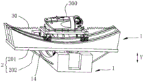
图1是本申请一个实施例的平衡承载装置设置在运输设备上的结构示意图;Fig. 1 is a schematic structural view of a balance carrying device according to an embodiment of the present application arranged on a transportation device;
图2是本申请一个实施例的平衡承载装置的轴测图;Fig. 2 is an axonometric view of a balanced bearing device according to an embodiment of the present application;
图3是本申请一个实施例的平衡承载装置的分解示意图;Fig. 3 is an exploded schematic diagram of a balance bearing device according to an embodiment of the present application;
图4是本申请一个实施例的平衡承载装置的俯视图;Fig. 4 is a top view of a balance bearing device according to an embodiment of the present application;
图5是本申请一个实施例的移动组件的结构示意图;Fig. 5 is a schematic structural diagram of a mobile assembly according to an embodiment of the present application;
图6是本申请一个实施例的移动单元的结构示意图;Fig. 6 is a schematic structural diagram of a mobile unit according to an embodiment of the present application;
图7是本申请一个实施例的移动单元的分解示意图;Fig. 7 is an exploded schematic diagram of a mobile unit according to an embodiment of the present application;
图8是本申请一个实施例的移动单元的正视图;Fig. 8 is the front view of the mobile unit of an embodiment of the present application;
图9是本申请一个实施例的移动单元的后视图;Figure 9 is a rear view of a mobile unit according to an embodiment of the present application;
图10是本申请一个实施例的移动单元的侧视图;Figure 10 is a side view of a mobile unit according to an embodiment of the present application;
图11是本申请另一个实施例的移动单元的侧视图;Fig. 11 is the side view of the mobile unit of another embodiment of the present application;
图12是本申请又一个实施例的移动单元的侧视图;Fig. 12 is a side view of a mobile unit according to yet another embodiment of the present application;
图13是本申请一个实施例的移动单元的局部结构示意图;FIG. 13 is a schematic diagram of a partial structure of a mobile unit according to an embodiment of the present application;
图14是是本申请再一个实施例的移动单元的分解示意图;Fig. 14 is an exploded schematic diagram of a mobile unit according to yet another embodiment of the present application;
图15是本申请另一个实施例的平衡承载装置的轴测图;Fig. 15 is an axonometric view of a balance bearing device according to another embodiment of the present application;
图16是本申请又一个实施例的平衡承载装置的轴测图;Fig. 16 is an axonometric view of a balance carrying device according to yet another embodiment of the present application;
图17是本申请再一个实施例的平衡承载装置设置于运输设备的结构示意图;Fig. 17 is a schematic structural view of a balance carrying device set on a transportation device according to another embodiment of the present application;
图18是本申请再一个实施例的平衡承载装置设置于运输设备时的倾斜状态示意图;Fig. 18 is a schematic diagram of a tilted state of a balance carrying device according to another embodiment of the present application when it is installed on a transportation device;
图19是本申请一个实施例的平衡承载装置的控制方法的流程图;Fig. 19 is a flow chart of a control method of a balance bearing device according to an embodiment of the present application;
图20是本申请一个实施例的平衡承载装置的控制流程图;Fig. 20 is a control flow chart of a balance bearing device according to an embodiment of the present application;
图21是本申请一个实施例的平衡承载装置的锁定流程图。Fig. 21 is a flowchart of locking the balance bearing device according to an embodiment of the present application.
其中:in:
100-平衡承载装置;100-balance bearing device;
1-移动组件;1 - Mobile components;
10-基座;11-引导轨;12-顶面;13-底面;14-弧形导槽;10-base; 11-guide rail; 12-top; 13-bottom; 14-arc guide groove;
20-移动件;20 - moving parts;
21-承载体;21 - carrier;
22-移动单元;22 - mobile unit;
221-支撑架;221 - support frame;
222-行走部件;2221-行走轮;2222-卡接凸起;222-walking parts; 2221-walking wheels; 2222-carding protrusions;
223-锁定部件;2231-安装体;2232-转动体;2232a-第一旋转体;2232b-第二旋转体;22321-主体部;22322-凸出部;2233-第一转动副;2234-第二转动副;2235-驱动组件;2235a-调节螺杆;2235b-螺帽;2235c-电动驱动件;2236-插接部;223-locking part; 2231-mounting body; 2232-rotating body; 2232a-first rotating body; 2232b-second rotating body; 22321-main body; Two rotating pairs; 2235-drive assembly; 2235a-adjusting screw; 2235b-nut; 2235c-electric drive; 2236-socket part;
30-调节件;301-第一电磁部;302-第二电磁部;30-regulator; 301-first electromagnetic part; 302-second electromagnetic part;
2-转接组件;201-过渡平台;202-支撑杆;2-transfer assembly; 201-transition platform; 202-support rod;
3-检测器;4-控制器;3-detector; 4-controller;
200-运输设备;300-待运输部件;200-transport equipment; 300-parts to be transported;
X-延伸方向;Y-层叠方向。X-extending direction; Y-stacking direction.
在附图中,相同的部件使用相同的附图标记。附图并未按照实际的比例绘制。In the figures, the same parts are given the same reference numerals. The figures are not drawn to scale.
具体实施方式Detailed ways
下面将详细描述本申请的各个方面的特征和示例性实施例。在下面的详细描述中,提出了许多具体细节,以便提供对本申请的全面理解。但是,对于本领域技术人员来说很明显的是,本申请可以在不需要这些具体细节中的一些细节的情况下实施。下面对实施例的描述仅仅是为了通过示出本申请的示例来提供对本申请的更好的理解。在附图和下面的描述中,至少部分的公知结构和技术没有被示出,以便避免对本申请造成不必要的模糊;并且,为了清晰,可能夸大了部分结构的尺寸。此外,下文中所描述的特征、结构或特性可以以任何合适的方式结合在一个或更多实施例中。Features and exemplary embodiments of various aspects of the present application will be described in detail below. In the following detailed description, numerous specific details are set forth in order to provide a thorough understanding of the application. It will be apparent, however, to one skilled in the art that the present application may be practiced without some of these specific details. The following description of the embodiments is only to provide a better understanding of the present application by showing examples of the present application. In the drawings and the following description, at least some well-known structures and techniques have not been shown in order to avoid unnecessarily obscuring the application; and, for clarity, the dimensions of some structures may have been exaggerated. Furthermore, the features, structures, or characteristics described hereinafter may be combined in any suitable manner in one or more embodiments.
下述描述中出现的方位词均为图中示出的方向,并不是对本申请的平衡承载装置及其控制方法的具体结构进行限定。在本申请的描述中,还需要说明的是,除非另有明确的规定和限定,术语“安装”、“连接”应做广义理解,例如,可以是固定连接,也可以是可拆卸连接,或一体地连接;可以是直接相连,也可以间接相连。对于本领域的普通技术人员而言,可视具体情况理解上述术语在本申请中的具体含义。The orientation words appearing in the following descriptions are all directions shown in the figure, and are not intended to limit the specific structure of the balance bearing device and its control method of the present application. In the description of this application, it should also be noted that unless otherwise specified and limited, the terms "installation" and "connection" should be understood in a broad sense, for example, it can be a fixed connection or a detachable connection, or Connected integrally; either directly or indirectly. For those of ordinary skill in the art, the specific meanings of the above terms in this application can be understood according to specific situations.
目前,风力发电机组的组成零部件需要根据风力发电机组预定的施工区域进行运输,零部件在运输的过程中,需要保证零部件的平衡,使其一直处于水平状态。尤其对于海上风力发电机组的运输,由于运输成本和海域的水深原因,导致现在海上风机运输船较小,从而在海上风力发电机组安装起吊过程中,由于运输船的晃动,导致主机等零部件失去平衡,要么发生安全风险,要么延长从运输船起吊的时间,无法实现和保证海上风机的高效率起吊,极大增加风力发电机组的安装成本。At present, the component parts of the wind power generating set need to be transported according to the predetermined construction area of the wind power generating set. During the transportation of the parts, it is necessary to ensure the balance of the parts so that they are always in a horizontal state. Especially for the transportation of offshore wind turbines, due to the transportation cost and the water depth of the sea area, the current offshore wind turbine transport ship is small, so that during the installation and lifting of offshore wind turbines, due to the shaking of the transport ship, the main engine and other components will be lost. Balance, either a safety risk will occur, or the lifting time from the transport ship will be prolonged, and the high-efficiency lifting of the offshore wind turbine cannot be realized and guaranteed, which greatly increases the installation cost of the wind turbine.
已有的解决方式,通常采用六自由度机械臂进行补偿,六自由度控制,控制方式较为复杂,平衡调节困难,且成本高昂。Existing solutions usually use a six-degree-of-freedom mechanical arm for compensation and six-degree-of-freedom control. The control method is relatively complicated, the balance adjustment is difficult, and the cost is high.
为了解决上述及时问题,本申请实施提供一种平衡承载装置,平衡承载装置能够满足待运输部件运输时的平衡需求,且成本低廉,利于控制。In order to solve the above timely problems, the present application provides a balance bearing device, which can meet the balance requirements of the parts to be transported, and is low in cost and easy to control.
为了更好地理解本申请,下面结合图1至图21根据本申请实施例的用于平衡承载装置及其控制方法进行详细描述。In order to better understand the present application, a detailed description will be given below of a load balancing device and a control method thereof according to an embodiment of the present application with reference to FIGS. 1 to 21 .
请参照图1至图5,本申请实施例提供的平衡承载装置100,设置于运输设备200,包括移动组件1,两个以上移动组件1层叠设置,每个移动组件1包括基座10、移动件20以及调节件30,基座10具有弧形的引导轨11,移动件20设置于基座10并能够在重力作用下沿引导轨11的延伸轨迹移动,调节件30连接于移动件20与基座10之间并能够限制移动件20沿引导轨11移动的极限位置。其中,相邻两个移动组件1的引导轨11的延伸方向X相交设置且其中一者的基座10与另一者的移动件20连接,在两个以上移动组件1的层叠方向Y,位于最顶层的移动组件1能够通过移动件20与待运输部件300连接。Please refer to Fig. 1 to Fig. 5, the
可选地,移动组件1的数量不做具体限定,可以为两个、三个甚至更多个。Optionally, the number of moving
可选地,各移动组件1中,任意两个移动组件1的基座10上引导轨11的延伸方向X相交。Optionally, in each moving
可选地,在层叠方向Y上,位于顶层的移动组件1的基座10上弧形引导轨11向位于底层的移动组件1所在方向凹陷。在层叠方向Y上,各移动组件1的弧形引导轨11沿同一方向凹陷,均向底层的移动组件1所在侧凹陷。弧形的引导轨11可以为圆弧形的引导轨11,也可以是椭圆弧形的引导轨11。Optionally, in the stacking direction Y, the arc-shaped
位于最顶层的移动组件1可以是平衡承载装置100放置在运输设备200上工作时,在层叠方向Y上最远离运输设备200设置的移动组件1。The
本申请实施例提供的平衡承载装置100,在使用时可以设置于运输车、运输船等运输设备200上,平衡承载装置100包括两个以上层叠设置的移动组件1,每个移动组件1包括基座10、移动件20以及调节件30,并且相邻两个移动组件1的引导轨11的延伸方向X相交设置且其中一者的基座10与另一者的移动件20连接,在对待运输部件300进行运输时,可以使得在两个以上移动组件1的层叠方向Y,位于最顶层的移动组件1能够通过移动件20与待运输部件300连接。由于基座10具有弧形的引导轨11,移动件20设置于基座10并能够沿引导轨11的延伸轨迹移动,使得当运输设备200发生倾斜时,对应的移动件20能够在重力作用下沿对应引导轨11的延伸轨迹移动,使得与待运输部件300连接的移动件20始终处于平衡位置,利于控制。相应设置的调节件30能够限制移动件20沿引导轨11移动的极限位置,避免移动件20与基座10分离,满足待运输部件300的平衡需求的基础上,能够保证运输安全,适用于海上等不稳定工况下部件的运输。The
同时,由于移动组件1的数量为两个以上,相邻两个移动组件1的引导轨11的延伸方向X相交设置且其中一者的基座10与另一者的移动件20连接,能够适应运输设备200在不同方向上的倾斜,并且移动组件1结构简单且可以模块化设计,能够降低平衡承载装置100整体的成本。At the same time, since the number of moving
请参照图5,作为一种可选地实施方式,本申请实施例提供的平衡承载装置100,其移动件20包括承载体21以及多个移动单元22,多个移动单元22间隔分布并分别与承载体21连接,各移动单元22分别与引导轨11可移动连接。Please refer to Fig. 5, as an optional implementation mode, in the
本申请实施例提供的平衡承载装置100,移动组件1采用上述结构形式,既能够保证与待运输部件300以及相邻两个移动组件1之间的连接需求,同时能够通过多个移动单元22与相应的引导轨11配合,使得当运输设备200发生晃动失去平衡时,利于移动件20在重力的作用下能够带动所连接的相邻的移动组件1或者待运输部件300沿着对应的引导轨11移动,保证待运输部件300的平衡需求。In the
可选地,承载体21可以为实心的座体结构,当然也可以为镂空的架子结构,承载体21上可以设置有连接接口,以利于与待运输部件300连接或者与相邻的承载组件的基座10连接。Optionally, the
可选地,移动单元22的数量可以为两个、三个甚至更多个。可选地,移动单元22可以成对设置,成对设置的移动单元22在承载体21上对称分布,以保证承载体21的受力平衡,进而保证运输安全。Optionally, the number of
在一些可选地实施例中,本申请实施例提供的平衡承载装置100,还包括转接组件2,相邻两个移动组件1之间连接有转接组件2。也就是说,相邻两个移动组件1可以通过转接组件2彼此间接连接,利于二者之间的连接需求。In some optional embodiments, the
作为一种可选地实施方式,本申请实施例提供的平衡承载装置100,转接组件2包括过渡平台201以及支撑杆202,过渡平台201位于相邻两个移动组件1之间,相邻两个移动组件1中一者的基座10上设置弧形导槽14,过渡平台201与相邻两个移动组件1中一者的移动件20连接并与另一者的基座10连接。支撑杆202的一端与过渡平台201铰接且另一端与弧形导槽14可移动连接。转接组件2采用上述结构,利于相邻两个移动组件1之间的连接。并且能保证相邻两层移动组件1中,其中一者的移动件20带动另一者移动时整体的稳定性。As an optional implementation mode, in the
在一些可选地实施例中,本申请实施例提供的平衡承载装置100,其调节件30可以包括伸缩缸,伸缩缸的缸体以及缸杆的一者与移动件20连接且另一者与基座10连接。调节件30采用伸缩缸的形式,可以通过限制伸缩缸的行程来限制移动件20的极限位置,避免移动件20与对应的基座10分离。同时,在伸缩缸的行程范围内,当移动件20移动时,伸缩缸能够随动,不会影响移动件20在重力作用下移动。In some optional embodiments, in the
可选地,调节件30与基座10以及移动件20分别采用铰接的方式相互连接。Optionally, the adjusting
请参照图6至图10,在一些可选地实施例中,本申请实施例提供的平衡承载装置100,移动单元22包括支撑架221、行走部件222以及锁定部件223,行走部件222通过锁定部件223与支撑架221连接,行走部件222能够沿引导轨11的延伸轨迹移动,锁定部件223用于锁定行走部件222在基座10上的位置。Please refer to Fig. 6 to Fig. 10, in some optional embodiments, the
本申请实施例提供的平衡承载装置100,通过使得移动单元22包括支撑架221、行走部件222以及锁定部件223,使其可以通过支撑架221与承载体21连接,并且支撑架221还可以为锁定部件223提供连接以及安装空间。而相应设置的行走部件222可以带动整个移动件20沿引导轨11的弧形轨迹运动,锁定部件223的设置可以锁定行走部件222在基座10上的位置,使得当平衡承载装置100在非工作状态下或者所在运输设备200倾斜角度较大预发生倾翻的情况下锁定行走部件222,避免移动件20沿引导轨11继续移动,节约能源,同时能够提高平衡承载装置100的安全性能。The
可选地,支撑架221可以采用框架式结构,支撑架221上设置有连接接口,用于与承载体21连接。Optionally, the
可选地,支撑架221可以为中空的框架结构体,锁定部件223至少部分位于支撑架221的中空腔内。通过上述设置,利于锁定部件223与支撑架221之间的配合,同时能够使得移动单元22整体结构紧凑,占用空间小。Optionally, the
参照图5至图10所示,作为一种可选地实施方式,本申请实施例提供的平衡承载装置100,在层叠方向Y,基座10具有相对设置的顶面12以及底面13,顶面12为向底面13所在方向凸出的弧形面,引导轨11设置于弧形面,行走部件222至少部分支撑于顶面12,行走部件222与引导轨11的一者至少部分伸入另一者的内部且彼此可移动连接。Referring to Figures 5 to 10, as an optional implementation mode, in the
基座10采用上述结构形式,并使得引导轨11设置于弧形面,利于弧形的引导轨11的形成。将行走部件222至少部分支撑于顶面12,能够增加基座10与行走部件222的接触面积,通过弧形面分担行走部件222所承受的压力,减小行走时的摩擦,保证行走部件222移动的顺畅性。同时,通过使得行走部件222与引导轨11的一者至少部分伸入另一者的内部且彼此可移动连接,能够限制行走部件222始终沿着引导轨11的延伸轨迹移动,避免行走部件222相对引导轨11发生偏移。The
可选地,基座10的底面13可以为平面,利于与相邻的移动组件1的移动件20连接。Optionally, the
作为一种可选地实施方式,本申请实施例提供的平衡承载装置100,引导轨11为弧形槽体,引导轨11由顶面12起始向靠近底面13所在侧凹陷形成,行走部件222包括行走轮2221以及与行走轮2221转动连接的卡接凸起2222,行走轮2221支撑于顶面12并转动连接于锁定部件223,卡接凸起2222卡接于引导轨11内并能够沿引导轨11的延伸方向X移动。As an optional implementation mode, in the
通过上述设置,能够通过卡接凸起2222与引导轨11之间的配合限制行走部件222沿着引导轨11的延伸轨迹移动,避免行走部件222相对引导轨11发生偏移,行走轮2221与顶面12滚动配合,利于行走部件222的移动,同时能够通过顶面12分担移动单元22所承受的压力。Through the above arrangement, the movement of the running
可选地,卡接凸起2222可以与行走轮2221转动连接,可选地,卡接凸起2222能够绕着行走轮2221的中轴线转动。Optionally, the engaging
参照图6至图10所示,可选地,卡接凸起2222可以成对设置并相对于设置行走轮2221在自身轴向上的两侧,当然,此为一种可选地实施方式。Referring to FIGS. 6 to 10 , optionally, the snap-in
参照图11所示,在有些实施例中,也可以使得卡接凸起2222的数量为一个并设置在行走轮2221在自身轴向上的一侧。As shown in FIG. 11 , in some embodiments, the number of
可以理解的是,当行走部件222与引导轨11的一者至少部分伸入另一者的内部且彼此可移动连接时,不限于上述结构形式。It can be understood that when one of the running
参照图12所示,在有些实施例中,也可以使得引导轨11为弧形凸起,引导轨11由顶面12起始向背离底面13所在侧凸出形成,行走部件222包括行走轮2221以及设置于行走轮2221上的卡槽2221a,行走轮2221支撑于顶面12,卡槽2221a卡接于引导轨11并能够沿引导轨11的延伸方向X移动。同样能够满足对行走轮2221的限位以及通过顶面12分担压力的要求。Referring to FIG. 12 , in some embodiments, the
参照图6至图12,作为一种可选地实施方式,本申请实施例提供的平衡承载装置100,其锁定部件223可以包括安装体2231以及转动体2232,安装体2231连接于支撑架221,转动体2232通过第一转动副2233与安装体2231转动连接,行走部件222通过第二转动副2234与转动体2232转动连接,第一转动副2233的转动轴线与第二转动副2234的转动轴线平行且间隔分布。Referring to FIGS. 6 to 12 , as an optional implementation, the locking
本申请实施例提供的平衡承载装置100,锁定部件223采用上述结构形式,能够通过安装体2231与支撑架221连接,为转动体2232以及行走部件222的安装提供支撑。由于转动体2232通过第一转动副2233与安装体2231转动连接,行走部件222通过第二转动副2234与转动体2232转动连接,使得行走部件222能够以第二转动副2234为转动中心相对转动体2232转动,进而带动移动件20整体沿着引导轨11的延伸轨迹移动。In the
同时,转动体2232可以带动行走部件222整体以第一转动副2233为旋转中心相对安装体2231转动,由于第一转动副2233的转动轴线与第二转动副2234的转动轴线平行且间隔设置,也就是说第一转动副2233偏离行走轮2221的旋转中心,使得转动体2232在以第一转动副2233转动的过程中,行走部件222做偏心运动,能够增大行走轮2221与其接触的支撑面之间摩擦力,如行走轮2221与顶面12的摩擦力,以限制行走部件222行走,实现锁定需求。At the same time, the
可选地,第一转动副2233可以包括第一转轴以及设置在第一转轴的轴向上至少一端的第一限位帽,第一转轴可以与转动体2232固定连接并与安装体2231转动连接,第一限位帽用于限制第一转轴在自身轴向上与安装体2231分离。Optionally, the first
可选地,第二转动副2234可以包括第二转轴以及设置于第二转轴的轴向上至少一端的第二限位帽,第二转轴可以与行走轮2221以及转动体2232的一者固定连接并与另一者转动连接,第二限位帽用于限制第二转轴在自身轴向上与行走轮2221或者转动体2232分离。Optionally, the second
作为一种可选地实施方式,本申请实施例提供的平衡承载装置100,转动体2232包括第一旋转体2232a以及第二旋转体2232b,安装体2231位于第一旋转体2232a以及第二旋转体2232b之间,第一转动副2233与第一旋转体2232a以及第二旋转体2232b固定连接并与安装体2231转动连接,行走部件222连接于第一旋转体2232a。As an optional implementation mode, in the
转动体2232采用上述结构形式,使得转动体2232以第一转动副2233为旋转中心转动时能够保证转动的平稳性,并且利于与行走部件222之间的连接。可选地,行走轮2221可以通过第二转动副2234与第一旋转体2232a转动连接。The
作为一种可选地实施方式,本申请实施例提供的锁定部件223还包括驱动组件2235,驱动组件2235驱动转动体2232以第一转动副2233为转动中心相对安装体2231转动。通过上述设置,可以通过驱动组件2235驱动转动体2232转动。当需要对行走部件222进行锁定时,可以通过驱动组件2235驱动转动体2232转动,进而使得转动体2232在以第一转动副2233转动的过程中,能够增大行走部件222与其接触的支撑面之间摩擦力,以限制行走部件222行走,实现锁定需求。As an optional implementation manner, the
在一些可选地实施例中,驱动组件2235包括调节螺杆2235a以及螺帽2235b,调节螺杆2235a的一端连接于基座10且另一端穿过第一旋转体2232a,螺帽2235b与调节螺杆2235a螺纹连接,螺帽2235b能够沿调节螺杆2235a的轴向移动并挤压第一旋转体2232a,以驱动转动体2232整体以第一转动副2233为中心相对安装体2231转动。In some optional embodiments, the driving
本申请实施例提供的平衡承载装置100,通过限定驱动组件2235包括调节螺杆2235a,可以使得调节螺杆2235a的一端连接在基座10上,调节螺杆2235a穿过第一旋转体2232a,在层叠方向Y上,螺帽2235b位于转动体2232背离基座10的一侧。当需要锁定行走部件222时,可以通过旋拧螺帽2235b,使得螺帽2235b沿调节螺杆2235a的轴向移动并挤压第一旋转体2232a,以驱动转动体2232整体以第一转动副2233为中心相对安装体2231转动,实现行走部件222的锁定。The
当需要解锁时,将调节螺杆2235a与基座10分离并解锁螺帽2235b即可。When unlocking is required, the
可选地,调节螺杆2235a可以沿着层叠方向Y延伸,利于对第一旋转体2232a进行驱动。Optionally, the adjusting
在一些可选地实施例中,本申请实施例提供的平衡承载装置100,驱动组件2235还可以包括电动驱动件2235c,电动驱动件2235c的一端与支撑架221连接且另一端与第二旋转体2232b配合,以驱动转动体2232整体以第一转动副2233为中心相对安装体2231转动。In some optional embodiments, in the
当需要对行走部件222进行锁定时,也可以控制电动驱动件2235c,使其驱动第二旋转体2232b转动,由于第二旋转体2232b通过第一转动副2233与第一旋转体2232a固定连接为一体,且第一转动副2233与安装体2231转动连接,因此当第二旋转体2232b转动时,将通过第一转动副2233带动第一旋转体2232a以第一转动副2233为旋转中心转动,同样能够实现行走部件222的锁定。When it is necessary to lock the
请参照图13所示,在一些可选地实施例中,第一旋转体2232a包括主体部22321以及凸出于主体部22321设置的凸出部22322,第一转动副2233以及第二转动副2234间隔设置于主体部22321,调节螺杆2235a穿过凸出部22322并与螺帽2235b连接,螺帽2235b沿调节螺杆2235a的轴向移动并挤压凸出部22322。Please refer to FIG. 13 , in some optional embodiments, the first
第一旋转体2232a采用上述结构形式,能够利于与调节螺杆2235a以及螺帽2235b进行配合,保证转动需求。The first
作为一种可选地实施方式,在调节螺杆2235a的轴向上,凸出部22322的延伸尺寸小于主体部22321的延伸尺寸,凸出部22322与螺帽2235b配合的表面为平面。通过上述设置,能够有效的避免调节螺杆2235a与螺帽2235b在对第一旋转体2232a驱动使其以第一转动副2233为旋转中心转动时与基座10之间产生干涉,利于第一旋转体2232a的转动,且能够增大第一旋转体2232a的转动范围。As an optional implementation manner, in the axial direction of the adjusting
在一些可选地实施例中,电动驱动件2235c包括伸缩件,伸缩件与第二旋转体2232b连接,伸缩件伸长或者缩短以驱动第二旋转体2232b带动第一旋转体2232a及行走部件222以第一转动副2233为中心转动。In some optional embodiments, the
电动驱动件2235c采用上述结构形式,结构简单,利于控制,其能够保证对第二旋转体2232b的驱动要求。The
作为一种可选地实施方式,电动驱动件2235c的伸缩方向可以与层叠方向Y相互垂直,第二旋转体2232b可以为条状结构体,电动驱动件2235c的驱动端可以连接在第二旋转体2232b的一侧并驱动第二旋转体2232b转动。As an optional implementation, the telescopic direction of the
参照图6至图13所示,在一些可选地实施例中,本申请实施例提供的平衡承载装置100,锁定部件223还包括插接部2236,插接部2236可拆卸连接于行走部件222、安装体2231以及转动体2232。能够进一步满足移动件20的锁定需求。Referring to FIGS. 6 to 13 , in some optional embodiments, in the
作为一种可选地实施方式,本申请实施例提供的平衡承载装置100,行走部件222的数量为多个,每个行走部件222分别对应设置有锁定部件223。通过上述设置,能够保证移动件20的移动需求,同时能够保证每个行走部件222的锁定需求,提高安全性能。As an optional implementation manner, in the
可选地,与同一支撑架221连接的行走部件222的数量可以为两个以上,以两个为例,两个行走部件222可以在引导轨11的延伸方向X上间隔分布,每个行走部件222可以对应设置有一个锁定部件223,每个锁定部件223的安装体2231与支撑架221连接,与同一支撑架221连接的各锁定部件223的安装体2231可以为一体式结构。Optionally, the number of running
参照图14所示,在有些实施例中,也可以使得与同一支撑架221连接的各锁定部件223的安装体2231也可以为分体式结构。Referring to FIG. 14 , in some embodiments, the mounting
在一些可选地实施例中,本申请实施例提供的平衡承载装置100,其移动组件1的数量可以为两个,两个移动组件1的引导轨11的延伸轨迹相互垂直。通过上述设置,使得平衡承载装置100能够带动待运输部件300在两个相互垂直的方向上利用重力调节平衡。结构简单,且能够满足利用重力自适应调节需求。In some optional embodiments, in the
可以理解的是,上述各实施例中调节件30采用伸缩缸只是一种可选地实施方式,但不限于此。It can be understood that the use of telescopic cylinders for the
请参照图15,在有些实施例中,也可以使得调节件30包括弹性体,弹性体的一端与移动件20连接且另一端与基座10连接。同样能够满足限位要求,同时不会对移动件20在重力作用下沿延伸轨迹移动功能产生影响。可选地,弹性体可以包括弹簧。Please refer to FIG. 15 , in some embodiments, the
调节件30通过胡克定理,位移最大时,会有回复力,可以缓解和降低角度的倾斜,同样能够满足限位效果。According to Hooke's theorem, the
可选地,当调节件30包括弹性体时,弹性体的数量可以为两个,两个弹性体在所在移动组件1的引导轨的延伸方向X上间隔分布在移动件20的两侧。Optionally, when the adjusting
请参照图16,在一些其他的实施例中,调节件30也可以包括电磁部件,电磁部件包括第一电磁部301以及第二电磁部302,第一电磁部301连接于移动件20,且第二电磁部302连接于基座10,第一电磁部301与第二电磁部302能够相互产生磁力作用。第一电磁部301以及第二电磁部302通过距离的改变,磁力会增大挥着减小,当距离最近时,磁力最大,吸力最强,距离远时,磁力减少,因此可以将第二电磁部302布置在锁定的极限点位置,通过正向和反向通电,实现磁力的吸引和排斥,也能够满足限位要求。Please refer to FIG. 16 , in some other embodiments, the adjusting
请参照图17以及图18,作为一种可选地实施方式,本申请实施例提供的平衡锁定装置,还包括检测器3以及控制器4,检测器3被配置为检测运输设备200的倾斜工况,控制器4被配置为当倾斜工况在预设阈值范围内时,保持各移动件20能够在重力作用下沿引导轨11移动,以使得用于与待运输部件300连接的移动件20处于平衡位置。Please refer to FIG. 17 and FIG. 18 , as an optional implementation mode, the balance locking device provided in the embodiment of the present application further includes a
也就是说,当倾斜工况在预设阈值范围内时,调节件30处于随动状态,当运输设备200发生倾斜时,对应倾斜方向上的移动件20可以在重力作用下沿着相应引导轨11的延伸轨迹移动,以自适应调节带运输部件的平衡,保证待运输部件300的安全。That is to say, when the tilting condition is within the preset threshold range, the adjusting
需要说明的是,本申请以上以及以下所提及的平衡位置是指用于与待运输部件300连接的移动件20的水平方向与水平面之间的夹角为0°,也就是说,与待运输部件300连接的移动件20用于支撑待运输部件300的表面处于水平状态且与水平面之间的夹角为0°。It should be noted that the equilibrium position mentioned above and below in this application means that the angle between the horizontal direction of the moving
可选地,检测器3可以包括位移传感器以及倾角传感器中的一者,检测器3可以设置于运输设备200上。Optionally, the
可选地,倾斜工况包括运输设备200相对于水平面的倾斜角度A,预设阈值范围包括-7°±0.5°≤A≤7°±0.5°。也就是说,运输设备200可以向前倾的角度小于等于7°±0.5°,或者向后倾斜角度小于等于7°±0.5°。Optionally, the inclined working condition includes an inclined angle A of the
可选地,在有些实施例中,倾斜工况还可以包括移动件20沿对应引导轨11的延伸方向X的位移B,预设阈值范围还包括B1-B2≤B≤B1+B2,其中,B1为用于连接待运输部件300的移动组件1的移动件20的重心与基座10的重心在层叠方向Y上重合时,调节件30在引导轨11的延伸方向X上的长度尺寸,B2为运输设备200的倾斜角度达到预定阈值时,用于连接待运输部件300的移动组件1的移动件20重心相对基座10的重心在其引导轨11的延伸方向X上的偏移尺寸。Optionally, in some embodiments, the tilting condition may also include the displacement B of the moving
作为一种可选地实施方式,本申请实施例提供的平衡承载装置100,控制器4还被配置为当倾斜工况超过预设阈值范围时,控制调节件30向移动件20提供与移动件20的移动方向相反的作用力。As an optional implementation mode, in the
也就是说当倾斜工况包括运输设备200相对于水平面的倾斜角度A且当A<-7°±0.5°或者A>7°±0.5°时,控制调节件30向移动件20提供与移动件20的移动方向相反的作用力。以避免移动件20继续移动与基座10分离。That is to say, when the inclination condition includes the inclination angle A of the
当倾斜工况包括移动件20沿对应引导轨11的延伸方向X的位移B且当B>B1+B2或者B<B1-B2时,控制调节件30向移动件20提供与移动件20的移动方向相反的作用力。以避免移动件20继续移动与基座10分离。When the tilting condition includes the displacement B of the moving
当然,当倾斜工况超过预设阈值范围时,控制器4还可以控制锁定各移动组件1的移动件20与基座10的相对位置。当包括驱动组件2235时,可以通过控制驱动组件2235的电动驱动件2235c,实现转动体2232带动行走部件222以第一转动副2233为旋转中心转动,实现锁定。Of course, when the tilt condition exceeds the preset threshold range, the
请参照图17至图19,另一方面,本申请还提供一种平衡承载装置100的控制方法,包括:Please refer to FIG. 17 to FIG. 19 , on the other hand, the present application also provides a control method for balancing the carrying
S100、检测平衡承载装置100所在运输设备200的倾斜工况;S100, detecting the inclination working condition of the
S200、当倾斜工况在预设阈值范围内时,保持各移动件20能够在重力作用下沿引导轨11移动,以使得用于与待运输部件300连接的移动件20处于平衡位置。S200 , when the tilting condition is within the preset threshold range, keep the moving
可选地,在步骤S100中,倾斜工况可以包括运输设备200相对于水平面的倾斜角度A和/或移动件20沿对应引导轨11的延伸方向X的位移B。Optionally, in step S100 , the inclination condition may include an inclination angle A of the
可选地,在步骤S200中当倾斜工况在预设阈值范围内时,调节件30处于随动状态,当运输设备200发生倾斜时,对应倾斜方向上的移动件20可以在重力作用下沿着相应引导轨11的延伸轨迹移动,以自适应调节带运输部件的平衡,保证待运输部件300的安全。Optionally, in step S200, when the tilting condition is within the preset threshold range, the adjusting
作为一种可选地实施方式,本申请实施例提供的平衡承载装置100的控制方法,还包括当所述倾斜工况超过所述预设阈值范围时,控制所述调节件30向所述移动件20提供与所述移动件20的移动方向相反的作用力,和/或,锁定各所述移动组件1的所述移动件20与所述基座10的相对位置。As an optional implementation, the method for controlling the
当倾斜工况可以包括运输设备200相对于水平面的倾斜角度A和/或移动件20沿对应引导轨11的延伸方向X的位移B。关于倾斜角度A的阈值范围以及位移B的阈值范围同上述各实施例中在平衡承载装置100中的限定,在此不再重复赘述。The inclined working condition may include the inclination angle A of the
作为一种可选地实施方式,本申请实施例提供的控制方法,还包括:检测平衡承载装置100处于非工装状态,给出锁定信号。As an optional implementation manner, the control method provided in the embodiment of the present application further includes: detecting that the
操作人员可以根据锁定信号控制驱动组件2235驱动转动体2232转动,进而实现移动件20位置的锁定。为了更好的区分,将通过调节螺杆2235a与螺帽2235b配合方式驱动第一旋转体2232a转动实现锁定的方式简称为机械锁定,将通过电动驱动件2235c驱动第二旋转体2232b带动第一旋转体2232a转动实现锁定的方式简称为电磁锁定。并且,可以使得平衡承载装置100包括两组移动组件1,与运输设备200连接的为下层移动组件,其调节件30为下层调节件,背离运输设备200设置并用于连接待运输部件300的移动组件1为上层移动组件,其调节件30为上层调节件。The operator can control the driving
为了更好的理解本申请实施例提供的控制方法,以下将以具体示例进行说明。In order to better understand the control method provided by the embodiment of the present application, a specific example will be used for description below.
请参照图20,当平衡承载装置100处于工作状态时,可以通过倾角传感器采集运输设备200的倾斜角度,当倾斜角度小于或者等于7度时,可以根据倾斜方向使得相应位置的调节件30作用。Please refer to FIG. 20 , when the
例如,当倾斜角度为前后倾角时,通过下层调节件控制,当左右倾角时,通过上层调节件控制,当前后以及左右均有倾角时,也就是说当前后左右倾角时,通过上层、下层调节件同时控制。For example, when the inclination angle is forward and backward, it is controlled by the lower adjustment member; when the left and right inclination is controlled, it is controlled by the upper adjustment member; components are controlled simultaneously.
当移动件20在移动的过程倾斜角度超过7°±0.5°,则锁定各所述移动组件1的移动件20与所述基座10的相对位置。具体可以采用电磁锁定方式进行锁定行走部件222。当检测运输设备200的倾斜角度小于或者等于7°±0.5°时,则解除电磁锁定,重新进行调节。When the inclination angle of the moving
而当通过倾角传感器检测的运输设备200的倾斜角度大于7°±0.5°时,则停航停止作业并通过电磁锁定方式锁定行走部件222。And when the inclination angle of the
请参照图21,对于平衡承载装置100的锁定可以参考如下示例,当平衡承载装置100处于工作状态需要对待运输部件300进行运输时,可以根据运输设备200的工况对电磁锁定进行供电,通过电磁锁定方式锁定行走部件222,并且将机械锁定结构解锁,当将待运输部件300吊装至平衡承载装置100准备运输后,电磁锁定解锁。Please refer to Fig. 21, the following example can be referred to for the locking of the
可以通过位移传感器检测移动件20沿对应引导轨11的延伸方向X的位移B是否在预设的阈值范围内,当B>B1+B2或者B<B1-B2时,采用电磁锁定方式锁定行走部件222,当B1-B2≤B≤B1+B2时,调节件30处于随动状态。The displacement sensor can be used to detect whether the displacement B of the moving
当然也可以通过倾角长安其检测运输设备200相对于水平面的倾斜角度A是否在预设的阈值范围内,当A<-7°±0.5°或者A>7°±0.5°时,采用电磁锁定方式锁定行走部件222,当-7°±0.5°≤A≤7°±0.5°时,调节件30处于随动状态。Of course, it is also possible to detect whether the inclination angle A of the
当平衡承载装置100处于非工作状态时,可以同时采用机械锁定以及电磁锁定来锁定行走部件222,保证安全性。When the
本申请实施例提供的平衡承载装置100的控制方法,能够待运输部件300的运输需求,并且当检测平衡承载装置100所在运输设备200的倾斜工况在预设阈值范围内时,保持各移动件20能够在重力作用下沿引导轨11移动,以使得用于与待运输部件300连接的移动件20处于平衡位置。实现重力作用下的自动调平衡效果,而当倾斜工况超出预设阈值范围时,采用锁定行走部件222的方式保证安全。The method for controlling the
虽然已经参考优选实施例对本申请进行了描述,但在不脱离本申请的范围的情况下,可以对其进行各种改进并且可以用等效物替换其中的部件。尤其是,只要不存在结构冲突,各个实施例中所提到的各项技术特征均可以任意方式组合起来。本申请并不局限于文中公开的特定实施例,而是包括落入权利要求的范围内的所有技术方案。While the application has been described with reference to a preferred embodiment, various modifications may be made and equivalents may be substituted for elements thereof without departing from the scope of the application. In particular, as long as there is no structural conflict, the technical features mentioned in the various embodiments can be combined in any manner. The present application is not limited to the specific embodiments disclosed herein, but includes all technical solutions falling within the scope of the claims.
Claims (25)
Priority Applications (6)
| Application Number | Priority Date | Filing Date | Title |
|---|---|---|---|
| CN202111276082.9A CN116066307B (en) | 2021-10-29 | 2021-10-29 | Balanced bearing device and control method thereof |
| AU2022376005A AU2022376005B2 (en) | 2021-10-29 | 2022-03-14 | Balance bearing device and control method therefor, and transportation apparatus |
| KR1020247011310A KR20240058911A (en) | 2021-10-29 | 2022-03-14 | Balancing loading device and its control method, transportation equipment |
| US18/701,438 US20240344556A1 (en) | 2021-10-29 | 2022-03-14 | Balance bearing device and control method thereof, transport equipment |
| EP22884935.2A EP4397855B1 (en) | 2021-10-29 | 2022-03-14 | Balance bearing device and control method therefor, and transportation apparatus |
| PCT/CN2022/080627 WO2023071018A1 (en) | 2021-10-29 | 2022-03-14 | Balance bearing device and control method therefor, and transportation apparatus |
Applications Claiming Priority (1)
| Application Number | Priority Date | Filing Date | Title |
|---|---|---|---|
| CN202111276082.9A CN116066307B (en) | 2021-10-29 | 2021-10-29 | Balanced bearing device and control method thereof |
Publications (2)
| Publication Number | Publication Date |
|---|---|
| CN116066307A true CN116066307A (en) | 2023-05-05 |
| CN116066307B CN116066307B (en) | 2024-10-22 |
Family
ID=86159039
Family Applications (1)
| Application Number | Title | Priority Date | Filing Date |
|---|---|---|---|
| CN202111276082.9A Active CN116066307B (en) | 2021-10-29 | 2021-10-29 | Balanced bearing device and control method thereof |
Country Status (6)
| Country | Link |
|---|---|
| US (1) | US20240344556A1 (en) |
| EP (1) | EP4397855B1 (en) |
| KR (1) | KR20240058911A (en) |
| CN (1) | CN116066307B (en) |
| AU (1) | AU2022376005B2 (en) |
| WO (1) | WO2023071018A1 (en) |
Citations (10)
| Publication number | Priority date | Publication date | Assignee | Title |
|---|---|---|---|---|
| GB482685A (en) * | 1936-02-20 | 1938-04-04 | Hydraulic Brake Co | Self-balancing dynamic systems |
| US20020029930A1 (en) * | 2000-07-31 | 2002-03-14 | Bassett Frederick N. | Low level scaffold with ballscrew drive |
| US20050188527A1 (en) * | 2002-02-08 | 2005-09-01 | Lutz Werner A. | Transport system |
| CN102616339A (en) * | 2011-01-30 | 2012-08-01 | 华锐风电科技(江苏)有限公司 | Transport installation ship of wind generation set and ship transport and installation method for wind generation set |
| US20170174422A1 (en) * | 2015-12-21 | 2017-06-22 | Bomag Gmbh | Transport Device For A Milling Unit, Transport Vehicle, And Method For Transporting A Milling Unit |
| CN108163678A (en) * | 2018-01-31 | 2018-06-15 | 金陵科技学院 | A kind of external distribution structure of skyscraper |
| CN109230481A (en) * | 2018-08-14 | 2019-01-18 | 中民筑友科技投资有限公司 | A kind of preform production line reinforced mesh eedle threader |
| CN208882674U (en) * | 2018-09-18 | 2019-05-21 | 江阴精力汽车装备有限公司 | Delivery platform |
| CN209241887U (en) * | 2018-12-18 | 2019-08-13 | 广州艾玩网络科技有限公司 | A directional picking shelf for a fresh machine |
| CN209836370U (en) * | 2019-01-14 | 2019-12-24 | 桐乡市雪松丝绸有限公司 | Automatic collection device of cocoon cooking machine |
Family Cites Families (17)
| Publication number | Priority date | Publication date | Assignee | Title |
|---|---|---|---|---|
| JP3030695U (en) * | 1996-04-30 | 1996-11-01 | 新興車輌株式会社 | Hand truck |
| CN2689286Y (en) * | 2004-03-20 | 2005-03-30 | 云南省电子计算中心 | Gyroscopic pan with dynamic balance for aerial camera |
| CN201782897U (en) * | 2010-08-17 | 2011-04-06 | 中国农业大学 | Self-balancing rescue stretcher |
| WO2012048719A1 (en) * | 2010-10-14 | 2012-04-19 | Wft Gmbh & Co. Kg | Turning device, especially for a rotor blade for a wind power station |
| US11052960B2 (en) * | 2018-02-22 | 2021-07-06 | Shane Chen | Transportation device with selective enabling of fore-aft auto-balancing |
| CN103506418A (en) * | 2013-09-09 | 2014-01-15 | 芜湖汉光立体停车设备有限公司 | Rocker-type compression roller thrust support |
| DK2947311T3 (en) * | 2014-05-23 | 2019-03-25 | Siemens Ag | Blade tip The clamping device |
| CN107922025B (en) * | 2015-08-10 | 2020-10-16 | 北京凌云智能科技有限公司 | Self-balancing carrier |
| NL2022121B1 (en) * | 2018-12-03 | 2020-06-30 | Carver B V | Self-balancing tilting vehicle with tilting speed and tilting torque controller |
| CN209175398U (en) * | 2019-01-04 | 2019-07-30 | 大连汇昌机械有限公司 | Levelling device is used in a kind of processing of machine tool accessory |
| CN210343348U (en) * | 2019-06-05 | 2020-04-17 | 中国建筑一局(集团)有限公司 | Derailment-proof wheel set device |
| US11629699B2 (en) * | 2019-09-06 | 2023-04-18 | Vestas Wind Systems A/S | Apparatuses for wind turbine blade railroad transportation and related systems and methods |
| CN112030623B (en) * | 2020-04-30 | 2022-07-01 | 中船第九设计研究院工程有限公司 | Track for underwater walking wheel not easy to derail |
| CN111878683A (en) * | 2020-08-27 | 2020-11-03 | 烟台职业学院 | A wearable portable electronic intelligent communication device |
| CN213323216U (en) * | 2020-10-21 | 2021-06-01 | 西南交通大学 | Self-adaptive leveling carrying trolley |
| CN112298528B (en) * | 2020-11-19 | 2025-05-06 | 淮阴工学院 | A self-balancing device for unmanned aerial vehicle and control method thereof |
| CN113307142B (en) * | 2021-05-14 | 2022-07-22 | 宝路汽车产业(十堰)有限公司 | Self-balancing anti-drop crane hook with auxiliary hook |
-
2021
- 2021-10-29 CN CN202111276082.9A patent/CN116066307B/en active Active
-
2022
- 2022-03-14 WO PCT/CN2022/080627 patent/WO2023071018A1/en not_active Ceased
- 2022-03-14 KR KR1020247011310A patent/KR20240058911A/en active Pending
- 2022-03-14 AU AU2022376005A patent/AU2022376005B2/en active Active
- 2022-03-14 EP EP22884935.2A patent/EP4397855B1/en active Active
- 2022-03-14 US US18/701,438 patent/US20240344556A1/en active Pending
Patent Citations (10)
| Publication number | Priority date | Publication date | Assignee | Title |
|---|---|---|---|---|
| GB482685A (en) * | 1936-02-20 | 1938-04-04 | Hydraulic Brake Co | Self-balancing dynamic systems |
| US20020029930A1 (en) * | 2000-07-31 | 2002-03-14 | Bassett Frederick N. | Low level scaffold with ballscrew drive |
| US20050188527A1 (en) * | 2002-02-08 | 2005-09-01 | Lutz Werner A. | Transport system |
| CN102616339A (en) * | 2011-01-30 | 2012-08-01 | 华锐风电科技(江苏)有限公司 | Transport installation ship of wind generation set and ship transport and installation method for wind generation set |
| US20170174422A1 (en) * | 2015-12-21 | 2017-06-22 | Bomag Gmbh | Transport Device For A Milling Unit, Transport Vehicle, And Method For Transporting A Milling Unit |
| CN108163678A (en) * | 2018-01-31 | 2018-06-15 | 金陵科技学院 | A kind of external distribution structure of skyscraper |
| CN109230481A (en) * | 2018-08-14 | 2019-01-18 | 中民筑友科技投资有限公司 | A kind of preform production line reinforced mesh eedle threader |
| CN208882674U (en) * | 2018-09-18 | 2019-05-21 | 江阴精力汽车装备有限公司 | Delivery platform |
| CN209241887U (en) * | 2018-12-18 | 2019-08-13 | 广州艾玩网络科技有限公司 | A directional picking shelf for a fresh machine |
| CN209836370U (en) * | 2019-01-14 | 2019-12-24 | 桐乡市雪松丝绸有限公司 | Automatic collection device of cocoon cooking machine |
Also Published As
| Publication number | Publication date |
|---|---|
| EP4397855A4 (en) | 2024-12-25 |
| WO2023071018A1 (en) | 2023-05-04 |
| KR20240058911A (en) | 2024-05-03 |
| EP4397855A1 (en) | 2024-07-10 |
| EP4397855B1 (en) | 2025-12-17 |
| CN116066307B (en) | 2024-10-22 |
| AU2022376005B2 (en) | 2025-09-11 |
| US20240344556A1 (en) | 2024-10-17 |
| AU2022376005A1 (en) | 2024-05-09 |
Similar Documents
| Publication | Publication Date | Title |
|---|---|---|
| JP7354278B2 (en) | cargo handling equipment | |
| CN105730173A (en) | Water, land, air and wall type quadruple robot | |
| US9073605B2 (en) | Boat with active suspension system | |
| CN205553833U (en) | Land, water and air wall no. 4 robot of dwelling | |
| JP2016224654A (en) | Autonomous travel robot | |
| CN107515614A (en) | Automated guided vehicle and its control method | |
| JP6910547B2 (en) | Mobile trolley | |
| CN116066307A (en) | Balanced bearing device and control method thereof | |
| CN211364195U (en) | Self-balancing moving platform | |
| CN104843599A (en) | Counterweight device of crane and crane with counterweight device | |
| CN116062300B (en) | Mobile device, balanced load-bearing equipment and control method thereof | |
| CN109823443A (en) | A kind of robot chassis with overturn-preventing structure | |
| CN211418609U (en) | Move and carry device and construction robot | |
| JP2022517026A (en) | Deformable electric vehicle | |
| CN217603761U (en) | Single-motor-driven double-shaft holder | |
| CN110792350B (en) | Self-balancing roller hanging device | |
| CN223751010U (en) | Floating chassis and automatic guide vehicle | |
| CN109867213A (en) | A kind of high altitude operation special purpose vehicle capstan head levelling device | |
| CN119821687A (en) | Suspension adjustment platform for bomb-hanging vehicle | |
| CN112540621A (en) | Novel unmanned aerial vehicle attitude control device and control method | |
| US20250171286A1 (en) | Lift vehicle drive system | |
| CN220642304U (en) | Port ship unloader load balancing hoisting apparatus | |
| CN114290351B (en) | Intelligent learning robot for children | |
| CN119038387B (en) | A device for preventing micro crane from swinging during hoisting | |
| CN219191971U (en) | Battery replacement equipment and battery replacement station |
Legal Events
| Date | Code | Title | Description |
|---|---|---|---|
| PB01 | Publication | ||
| PB01 | Publication | ||
| SE01 | Entry into force of request for substantive examination | ||
| SE01 | Entry into force of request for substantive examination | ||
| GR01 | Patent grant | ||
| GR01 | Patent grant |