CN115813767A - An auxiliary medicine feeding device - Google Patents
An auxiliary medicine feeding device Download PDFInfo
- Publication number
- CN115813767A CN115813767A CN202310055275.4A CN202310055275A CN115813767A CN 115813767 A CN115813767 A CN 115813767A CN 202310055275 A CN202310055275 A CN 202310055275A CN 115813767 A CN115813767 A CN 115813767A
- Authority
- CN
- China
- Prior art keywords
- outer sleeve
- liquid outlet
- groove
- ring
- conductive
- Prior art date
- Legal status (The legal status is an assumption and is not a legal conclusion. Google has not performed a legal analysis and makes no representation as to the accuracy of the status listed.)
- Withdrawn
Links
Images


Landscapes
- Infusion, Injection, And Reservoir Apparatuses (AREA)
Abstract
本发明提供了一种辅助喂药装置,属于医疗器械技术领域,该装置包括外套筒、注射筒、连接套、橡胶嘴和控制器,注射筒设置于外套筒的内部,外套筒的内壁开设有环形槽,环形槽的内部设置有加热丝,外套筒的另一端外侧开设有避让槽,橡胶嘴的顶部内嵌于避让槽的内部,连接套设置于橡胶嘴的外侧,注射筒的内部设置有活塞片,注射筒的底端连接有出液管,出液管的内部设置有涡轮,外套筒的内部设置有磁电转换器,橡胶嘴的底部外表面环形阵列开设有出液口,出液口的一侧设置有金属感温环,控制器设置于外套筒的外表面,该装置解决了喂药器功能单一、不便于控制喂药剂量,使用麻烦,容易造成药剂浪费的问题。
The invention provides an auxiliary drug feeding device, which belongs to the technical field of medical devices. The device includes an outer sleeve, an injection sleeve, a connecting sleeve, a rubber nozzle and a controller. The injection sleeve is arranged inside the outer sleeve, and the outer sleeve There is an annular groove on the inner wall, a heating wire is arranged inside the annular groove, and an escape groove is opened on the outside of the other end of the outer sleeve, the top of the rubber nozzle is embedded in the inside of the avoidance groove, the connecting sleeve is arranged on the outside of the rubber nozzle, and the injection barrel There is a piston piece inside, the bottom end of the injection barrel is connected with a liquid outlet pipe, the inside of the liquid outlet pipe is provided with a turbine, the inside of the outer sleeve is provided with a magnetoelectric converter, and the bottom outer surface of the rubber nozzle is provided with an outlet pipe in an annular array. There is a metal temperature-sensing ring on one side of the liquid outlet and the liquid outlet, and the controller is installed on the outer surface of the outer sleeve. This device solves the problem that the drug feeder has a single function and is inconvenient to control the dosage of the drug. waste problem.
Description
技术领域technical field
本发明涉及口服药物的器具技术领域,具体涉及一种辅助喂药装置。The invention relates to the technical field of appliances for oral administration of medicines, in particular to an auxiliary medicine feeding device.
背景技术Background technique
儿科患者由于生长发育的特点,因而在生理、认知、社会心理等方面与成年人存在较大差异,并使儿科患者在医疗照护环境中存在更多风险,一般新生儿药物多为颗粒状溶剂或糖浆,由于药物本身具有一定的气味,因此婴幼儿患者容易出现抗拒、挣扎等行为,从而导致喂药过程繁琐且效率低下,而药量达不到,又起不到治疗的效果。Due to the characteristics of growth and development, pediatric patients are quite different from adults in terms of physiology, cognition, and social psychology, which makes pediatric patients more risky in the medical care environment. Generally, newborn drugs are mostly granular solvents Or syrup, because the medicine itself has a certain smell, so infants and young children are prone to resistance, struggle and other behaviors, which leads to cumbersome and inefficient feeding process, and the dose of medicine cannot be reached, and the therapeutic effect cannot be achieved.
随着临床护理技术的提高,喂药器也得到了技术改进,但是现有技术在使用时大多只具备有单纯的喂药功能,通过按压将药剂挤入婴幼儿口腔内,在疏忽时由于力度过大,容易造成喂药过快,导致婴幼儿呛药的危险,而且,大部分喂药器使用麻烦,功能单一,不便于控制喂药计量,容易造成药剂浪费。With the improvement of clinical nursing technology, the medicine feeding device has also been technically improved, but most of the existing technologies only have a simple medicine feeding function when used, and the medicine is squeezed into the mouth of the infant by pressing, and the medicine is squeezed into the mouth of the infant when it is negligent. If it is too large, it is easy to cause the medicine to be fed too quickly, causing the danger of infants and young children choking on the medicine. Moreover, most medicine feeding devices are troublesome to use, have single functions, are not easy to control the dosage of medicine feeding, and easily cause waste of medicine.
发明内容Contents of the invention
本发明实施例提供了一种辅助喂药装置,旨在解决上述背景技术中提出的喂药器功能单一、不便于控制喂药剂量,使用麻烦。容易造成药剂浪费的问题。The embodiment of the present invention provides an auxiliary drug feeding device, which aims to solve the problem that the drug feeding device proposed in the background art has a single function, is inconvenient to control the feeding dose, and is troublesome to use. It is easy to cause the problem of medicament waste.
鉴于上述问题,本发明提出的技术方案是:In view of the problems referred to above, the technical solution proposed by the present invention is:
一种辅助喂药装置,包括外套筒、注射筒、连接套、橡胶嘴和控制器,所述外套筒呈中空圆柱形结构,所述注射筒设置于所述外套筒的内部,所述外套筒的一端开设有沉头槽,所述沉头槽的底部开设有卡槽,所述注射筒的一端设置有卡环,所述卡环内嵌于所述卡槽的内部,所述外套筒的内壁开设有环形槽,所述环形槽的内部设置有加热丝,所述外套筒的另一端外侧开设有避让槽,所述橡胶嘴设置于所述外套筒的一端,所述橡胶嘴的顶部内嵌于所述避让槽的内部,所述连接套设置于所述橡胶嘴的外侧,所述注射筒的内部设置有活塞片,所述活塞片的顶部连接有推杆,所述注射筒的底端连接有出液管,所述出液管的内部设置有涡轮,所述外套筒的内部设置有磁电转换器,所述磁电转换器与所述涡轮的中心位置相对应,所述出液管的端部与所述橡胶嘴的顶部连接,所述橡胶嘴的底部外表面环形阵列开设有出液口,所述出液口的一侧设置有金属感温环,所述控制器设置于所述外套筒的外表面,所述磁电转换器和所述金属感温环的输出端均与所述控制器的输入端电性连接。An auxiliary drug feeding device, comprising an outer sleeve, an injection sleeve, a connecting sleeve, a rubber nozzle and a controller, the outer sleeve is a hollow cylindrical structure, the injection sleeve is arranged inside the outer sleeve, and the One end of the outer sleeve is provided with a countersunk groove, and the bottom of the countersunk groove is provided with a card slot, and one end of the injection barrel is provided with a snap ring, and the snap ring is embedded in the inside of the card slot, so The inner wall of the outer sleeve is provided with an annular groove, the interior of the annular groove is provided with a heating wire, the outer side of the other end of the outer sleeve is provided with an escape groove, and the rubber nozzle is arranged at one end of the outer sleeve. The top of the rubber nozzle is embedded in the avoidance groove, the connecting sleeve is arranged on the outside of the rubber nozzle, a piston piece is arranged inside the injection barrel, and a push rod is connected to the top of the piston piece , the bottom end of the syringe is connected with a liquid outlet pipe, the inside of the liquid outlet pipe is provided with a turbine, the inside of the outer sleeve is provided with a magnetoelectric converter, and the magnetoelectric converter and the turbine Corresponding to the center position, the end of the liquid outlet pipe is connected to the top of the rubber nozzle, and the bottom outer surface of the rubber nozzle is provided with a liquid outlet in an annular array, and one side of the liquid outlet is provided with a metal sensor. The temperature ring, the controller is arranged on the outer surface of the outer sleeve, and the output ends of the magnetoelectric converter and the metal temperature sensing ring are both electrically connected to the input end of the controller.
为了更好的实现本发明技术方案,还采用了如下技术措施。In order to better realize the technical solution of the present invention, the following technical measures are also adopted.
进一步的,所述沉头槽的内部转动设置有两个卡扣,所述卡扣的一端与所述卡环的顶部抵接,所述加热丝呈螺旋分布,且与所述注射筒的外表面贴合,所述外套筒的内壁设置有温度传感器,所述温度传感器与所述注射筒的底部接触,所述温度传感器的输出端与所述控制器的输入端电性连接,所述加热丝的输入端与所述控制器的输出端电性连接。Further, the inner rotation of the countersunk groove is provided with two buckles, one end of the buckle abuts against the top of the snap ring, the heating wire is distributed in a spiral, and is connected to the outer surface of the injection barrel. Surface bonding, the inner wall of the outer sleeve is provided with a temperature sensor, the temperature sensor is in contact with the bottom of the syringe, the output end of the temperature sensor is electrically connected to the input end of the controller, the The input end of the heating wire is electrically connected with the output end of the controller.
进一步的,所述注射筒的底部呈锥形结构,所述活塞片与所述注射筒的内壁滑动配合,所述活塞片的底部形状与所述注射筒的底部形状相适配,所述注射筒的顶部中心设置有导向环,所述导向环与所述推杆间隙配合,所述推杆的顶端贯穿所述导向环后延伸至所述注射筒的外部。Further, the bottom of the injection cylinder has a conical structure, the piston piece is slidingly fitted with the inner wall of the injection cylinder, the shape of the bottom of the piston piece is adapted to the bottom shape of the injection cylinder, and the injection A guide ring is provided at the center of the top of the cylinder, and the guide ring is loosely matched with the push rod, and the top end of the push rod passes through the guide ring and extends to the outside of the syringe.
进一步的,所述涡轮的中心固定连接有中心轴,所述涡轮的两侧均设置有固定架,所述固定架呈“十”字形结构,所述固定架的端部均与所述出液管的内壁固定连接,所述中心轴的两端分别与两个所述固定架的中心转动连接。Further, the center of the turbine is fixedly connected with a central shaft, and both sides of the turbine are provided with fixing frames, and the fixing frames are in the shape of a "ten", and the ends of the fixing frames are connected with the outlet of the liquid. The inner wall of the pipe is fixedly connected, and the two ends of the central shaft are respectively connected to the centers of the two fixed frames in rotation.
进一步的,所述磁电转换器的内部设置有电磁线圈、永磁铁和信号放大器,所述电磁线圈套设于所述永磁铁的外侧,所述电磁线圈的中心轴与所述涡轮的中心轴相垂直,所述电磁线圈的输出端与所述信号放大器电性连接,所述信号放大器的输出端与所述控制器的输入端电性连接。Further, the inside of the magnetoelectric converter is provided with an electromagnetic coil, a permanent magnet and a signal amplifier, the electromagnetic coil is sleeved on the outside of the permanent magnet, the central axis of the electromagnetic coil and the central axis of the turbine Vertically, the output end of the electromagnetic coil is electrically connected to the signal amplifier, and the output end of the signal amplifier is electrically connected to the input end of the controller.
进一步的,所述橡胶嘴的顶部中心开设有密封槽,所述密封槽的内壁设置有密封圈,所述出液管的底端延伸至所述密封槽的内部,所述密封圈与所述出液管的外表面抵接,所述密封槽的底部中心开设有药液流道,所述药液流道与所述出液口连通,所述出液口呈倾斜设置。Further, the top center of the rubber nozzle is provided with a sealing groove, the inner wall of the sealing groove is provided with a sealing ring, and the bottom end of the liquid outlet pipe extends to the inside of the sealing groove, and the sealing ring is connected to the sealing groove. The outer surface of the liquid outlet pipe is in contact with each other, and the center of the bottom of the sealing groove is provided with a liquid medicine flow channel, and the liquid medicine flow channel communicates with the liquid outlet, and the liquid outlet is arranged obliquely.
进一步的,所述外套筒的底端外侧开设有外螺纹,所述橡胶嘴的外侧设置有固定环,所述固定环的顶部设置有导向部,所述避让槽的内部开设有导向槽,所述导向部内嵌于所述导向槽的内部,所述固定环的一侧与所述外套筒的底端抵接,所述固定环的另一侧与所述连接套的内部抵接,所述连接套的顶端开设有内螺纹,所述内螺纹与所述外螺纹相配合。Further, the outside of the bottom end of the outer sleeve is provided with external threads, the outside of the rubber nozzle is provided with a fixing ring, the top of the fixing ring is provided with a guide part, and the inside of the avoidance groove is provided with a guide groove, The guide part is embedded in the guide groove, one side of the fixing ring abuts against the bottom end of the outer sleeve, and the other side of the fixing ring abuts against the inside of the connecting sleeve , the top end of the connecting sleeve is provided with an internal thread, and the internal thread is matched with the external thread.
进一步的,所述外套筒的内部开设有两个第一导电槽,所述第一导电槽的内部设置有导电柱和弹簧件,所述弹簧件的两端分别与所述第一导电槽的底壁和所述导电柱的端部抵接,所述橡胶嘴的顶部开设有两个第二导电槽,所述第二导电槽的内部设置有导电片,所述导电柱插入至所述第二导电槽的内部后与所述导电片抵接,所述金属感温环与所述导电片电性连接,所述导电柱与所述控制器电性连接。Further, the inside of the outer sleeve is provided with two first conductive grooves, and the inside of the first conductive groove is provided with a conductive post and a spring member, and the two ends of the spring member are connected to the first conductive groove respectively. The bottom wall of the rubber nozzle abuts against the end of the conductive column, and the top of the rubber nozzle is provided with two second conductive slots, and a conductive piece is provided inside the second conductive slot, and the conductive column is inserted into the The inside of the second conductive groove is then in contact with the conductive sheet, the metal temperature sensing ring is electrically connected to the conductive sheet, and the conductive column is electrically connected to the controller.
进一步的,所述外套筒的顶端两侧对称设置有指环。Further, finger rings are arranged symmetrically on both sides of the top end of the outer sleeve.
进一步的,所述控制器的外侧设置有显示屏和控制按钮,所述显示屏和所述控制按钮均与所述控制器电性连接。Further, a display screen and control buttons are arranged on the outside of the controller, and both the display screen and the control buttons are electrically connected to the controller.
相对于现有技术而言,本发明的有益效果是:Compared with the prior art, the beneficial effects of the present invention are:
(1)该装置通过外套筒连接注射筒和橡胶嘴,由橡胶嘴向婴幼儿口中注射药液,橡胶嘴出液口倾斜设置于侧边,防止药剂直冲咽喉造成呛药的危险,保障使用安全,出液口内设置的涡轮在药剂流动使作用于磁电转换器上,用于计量药剂流量,精准控制喂药量,有效提高治疗效果;(1) The device connects the injection cylinder and the rubber nozzle through the outer sleeve, and the rubber nozzle injects the liquid medicine into the mouth of infants and young children. It is safe to use. The turbine installed in the liquid outlet acts on the magnetoelectric converter during the flow of the medicine, which is used to measure the flow of the medicine, accurately control the dosage of the medicine, and effectively improve the therapeutic effect;
(2)该装置拿取操作方便,通过加热丝能保持注射筒内药剂的温度,保持药剂疗效,减少重复配药的步骤,避免药剂浪费,装置连接简单可靠,避免药剂外漏,且拆装清洗消毒方便,降低了护理人员的工作强度;(2) The device is easy to take and operate. The heating wire can maintain the temperature of the medicine in the injection cylinder, maintain the curative effect of the medicine, reduce the steps of repeated dispensing, and avoid the waste of medicine. Disinfection is convenient, reducing the work intensity of nursing staff;
(3)该装置集成有体温测量、流量检测、保温加热、定时喂药提醒等功能,操作简单,使用效率高,综合实用性强。(3) The device integrates functions such as body temperature measurement, flow detection, heat preservation and heating, and regular feeding reminders. It is easy to operate, high in use efficiency, and strong in comprehensive practicability.
上述说明仅是本发明技术方案的概述,为了能够更清楚了解本发明的技术手段,而可依照说明书的内容予以实施,并且为了让本发明的上述和其它目的、特征和优点能够更明显易懂,以下特举本发明的具体实施方式。The above description is only an overview of the technical solution of the present invention. In order to better understand the technical means of the present invention, it can be implemented according to the contents of the description, and in order to make the above and other purposes, features and advantages of the present invention more obvious and understandable , the specific embodiments of the present invention are enumerated below.
附图说明Description of drawings
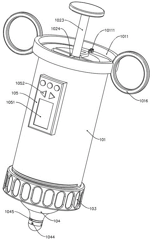
图1为本发明实施例公开的一种辅助喂药装置的结构示意图;Fig. 1 is a schematic structural view of an auxiliary drug feeding device disclosed in an embodiment of the present invention;
图2为本发明实施例公开的一种辅助喂药装置的分解结构示意图;Fig. 2 is a schematic diagram of an exploded structure of an auxiliary drug feeding device disclosed in an embodiment of the present invention;
图3为图2中A处的放大视图;Fig. 3 is the enlarged view of place A in Fig. 2;
图4为本发明实施例公开的外套筒的结构示意图;Fig. 4 is a schematic structural view of an outer sleeve disclosed by an embodiment of the present invention;
图5为本发明实施例公开的一种辅助喂药装置的剖视结构示意图;Fig. 5 is a schematic cross-sectional structure diagram of an auxiliary drug feeding device disclosed in an embodiment of the present invention;
图6为图5中A处的放大视图;Fig. 6 is the enlarged view of place A in Fig. 5;
图7为图5中B处的放大视图;Fig. 7 is the enlarged view of place B in Fig. 5;
图8为图5中C处的放大视图;Fig. 8 is the enlarged view of place C in Fig. 5;
图9为图5中D处的放大视图;Figure 9 is an enlarged view at D in Figure 5;
图10为本发明实施例公开的一种辅助喂药装置的电连接示意图。Fig. 10 is a schematic diagram of electrical connection of an auxiliary drug feeding device disclosed in an embodiment of the present invention.
附图标记:101、外套筒;1011、沉头槽;10111、卡扣;1012、卡槽;1013、环形槽;10131、加热丝;1014、外螺纹;1015、避让槽;10151、导向槽;1016、指环;1017、磁电转换器;10171、电磁线圈;10172、永磁铁;10173、信号放大器;1018、温度传感器;1019、第一导电槽;10191、导电柱;10192、弹簧件;102、注射筒;1021、卡环;1022、活塞片;1023、推杆;1024、导向环;1025、出液管;10251、涡轮;10252、中心轴;10253、固定架;103、连接套;1031、内螺纹;104、橡胶嘴;1041、固定环;10411、导向部;1042、密封槽;10421、密封圈;1043、药液流道;1044、出液口;1045、金属感温环;1046、第二导电槽;10461、导电片;105、控制器;1051、显示屏;1052、控制按钮。Reference signs: 101, outer sleeve; 1011, countersunk groove; 10111, buckle; 1012, card groove; 1013, annular groove; 10131, heating wire; 1014, external thread; 1015, avoidance groove; 10151, guide groove ;1016, ring; 1017, magnetoelectric converter; 10171, electromagnetic coil; 10172, permanent magnet; 10173, signal amplifier; 1018, temperature sensor; , injection barrel; 1021, snap ring; 1022, piston sheet; 1023, push rod; 1024, guide ring; 1025, liquid outlet pipe; 10251, turbine; 10252, central shaft; , internal thread; 104, rubber nozzle; 1041, fixed ring; 10411, guide part; 1042, sealing groove; 10421, sealing ring; 1043, liquid medicine flow channel; 1044, liquid outlet; , the second conductive groove; 10461, the conductive sheet; 105, the controller; 1051, the display screen; 1052, the control button.
实施方式Implementation
为使本发明实施方式的目的、技术方案和优点更加清楚,下面将结合本发明实施方式中的附图,对本发明实施方式中的技术方案进行清楚、完整地描述,显然,所描述的实施方式是本发明一部分实施方式,而不是全部的实施方式。基于本发明中的实施方式,本领域普通技术人员在没有作出创造性劳动前提下所获得的所有其他实施方式,都属于本发明保护的范围。In order to make the purpose, technical solutions and advantages of the embodiments of the present invention clearer, the technical solutions in the embodiments of the present invention will be clearly and completely described below in conjunction with the accompanying drawings in the embodiments of the present invention. Obviously, the described embodiments It is some embodiments of the present invention, but not all of them. Based on the implementation manners in the present invention, all other implementation manners obtained by persons of ordinary skill in the art without creative efforts fall within the protection scope of the present invention.
因此,以下对在附图中提供的本发明的实施方式的详细描述并非旨在限制要求保护的本发明的范围,而是仅仅表示本发明的选定实施方式。基于本发明中的实施方式,本领域普通技术人员在没有作出创造性劳动前提下所获得的所有其他实施方式,都属于本发明保护的范围。Accordingly, the following detailed description of the embodiments of the invention provided in the accompanying drawings is not intended to limit the scope of the claimed invention, but merely represents selected embodiments of the invention. Based on the implementation manners in the present invention, all other implementation manners obtained by persons of ordinary skill in the art without creative efforts fall within the protection scope of the present invention.
实施例Example
参照附图1-图10所示,本发明提供一种技术方案:一种辅助喂药装置,包括外套筒101、注射筒102、连接套103、橡胶嘴104和控制器105,外套筒101呈中空圆柱形结构,注射筒102设置于外套筒101的内部,注射筒102内用于盛装配好的药剂,在喂药装置使用前,利用注射筒102负压抽吸药剂,外套筒101的一端开设有沉头槽1011,沉头槽1011的底部开设有卡槽1012,注射筒102的一端设置有卡环1021,卡环1021内嵌于卡槽1012的内部,卡槽1012呈异形结构,卡环1021卡入卡槽1012内用于注射筒102的限位固定,防止注射筒102在使用时转动,外套筒101的内壁开设有环形槽1013,环形槽1013的内部设置有加热丝10131,加热丝10131用于保持药剂恒温,减少重复配药次数,外套筒101的另一端外侧开设有避让槽1015,橡胶嘴104设置于外套筒101的一端,橡胶嘴104的顶部内嵌于避让槽1015的内部,橡胶嘴104采用食品级材质,橡胶嘴104方便婴幼儿吮吸,减缓抗拒情绪,利于喂药,连接套103设置于橡胶嘴104的外侧,连接套103用于固定橡胶嘴104,使其保持与注射筒102的密封连接,注射筒102的内部设置有活塞片1022,活塞片1022的顶部连接有推杆1023,推杆1023将按压力作用于活塞片1022上,活塞片1022将注射筒102内的药剂挤出,注射筒102的底端连接有出液管1025,出液管1025的内部设置有涡轮10251,外套筒101的内部设置有磁电转换器1017,磁电转换器1017与涡轮10251的中心位置相对应,出液管1025的端部与橡胶嘴104的顶部连接,出液管1025将注射筒102内的药剂导流至橡胶嘴104内,涡轮10251与磁电转换器1017的配合用于检测出液管1025内的流量,从而精准控制喂药量,药液流经出液管1025时带动涡轮10251旋转,涡轮10251叶片切割磁电转换器1017产生的磁力线,通过周期变化,转换形成流速信号,再经换算得到药剂流量值,橡胶嘴104的底部外表面环形阵列开设有出液口1044,进入橡胶嘴104的药剂由出液口1044排入婴幼儿口中,出液口1044的一侧设置有金属感温环1045,金属感温环1045用于婴幼儿吮吸药剂时与幼儿舌头接触同步测量口腔体温,方便病情判断,节省时间,提高装置功能性,控制器105设置于外套筒101的外表面,磁电转换器1017和金属感温环1045的输出端均与控制器105的输入端电性连接,控制器105用于接收采集信号,并进行相应的处理和显示,同时可根据护理人员使用需求进行参数设置,从而向各传感器及电力机构输出控制信号。With reference to accompanying drawings 1-shown in Figure 10, the present invention provides a kind of technical scheme: a kind of auxiliary medicine feeding device, comprises
本发明实施例还通过以下技术方案进行实现。Embodiments of the present invention are also implemented through the following technical solutions.
在本发明的实施例中,沉头槽1011的内部转动设置有两个卡扣10111,卡扣10111的一端与卡环1021的顶部抵接,卡扣10111在注射筒102装入外套筒101后,将注射筒102顶部限位,防止注射筒102脱出,卡扣10111旋转使用,操作简单,加热丝10131呈螺旋分布,且与注射筒102的外表面贴合,加热丝10131通电后发热,将热量及时传递至注射筒102内,降低能耗,提高传热效率,外套筒101的内壁设置有温度传感器1018,温度传感器1018与注射筒102的底部接触,温度传感器1018的输出端与控制器105的输入端电性连接,加热丝10131的输入端与控制器105的输出端电性连接,温度传感器1018实时检测注射筒102外表的温度,控制器105接收信号后根据护理人员设置的参数控制加热丝10131启停,保持注射筒102内药剂恒温,保证药剂疗效,避免药剂浪费。In the embodiment of the present invention, two
在本发明的实施例中,注射筒102的底部呈锥形结构,活塞片1022与注射筒102的内壁滑动配合,活塞片1022的底部形状与注射筒102的底部形状相适配,锥形结构方便注射筒102内药剂的排空,也方便了注射筒102日常清洗杀菌,注射筒102的顶部中心设置有导向环1024,导向环1024与推杆1023间隙配合,推杆1023的顶端贯穿导向环1024后延伸至注射筒102的外部,导向环1024用于推杆1023的导向限位,推杆1023沿导向环1024的中心轴10252推拉,保持活塞片1022与注射筒102内壁的有效配合,提高使用寿命。In the embodiment of the present invention, the bottom of the
在本发明的实施例中,涡轮10251的中心固定连接有中心轴10252,涡轮10251的两侧均设置有固定架10253,固定架10253呈“十”字形结构,固定架10253的端部均与出液管1025的内壁固定连接,中心轴10252的两端分别与两个固定架10253的中心转动连接,固定架10253用于涡轮10251的安装,中心轴10252两端端部均呈圆弧状,起到导流作用,防止药液冲击,稳定液体流速,降低对涡轮10251旋转的干扰。In the embodiment of the present invention, the center of the
在本发明的实施例中,磁电转换器1017的内部设置有电磁线圈10171、永磁铁10172和信号放大器10173,电磁线圈10171套设于永磁铁10172的外侧,电磁线圈10171的中心轴10252与涡轮10251的中心轴10252相垂直,电磁线圈10171的输出端与信号放大器10173电性连接,信号放大器10173的输出端与控制器105的输入端电性连接,感应线圈检测永磁铁10172所产生的磁力线,当磁电转化器对应的涡轮10251在药液流动下发生转动时,涡轮10251的叶片切割永磁铁10172所产生的磁力线,感应线圈检测磁通周期变化,形成角速度信号,并通过信号放大器10173将信号放大处理,匹配控制器105的接收频率,将磁电转换器1017的信号稳定传输至控制器105上。In an embodiment of the present invention, an
在本发明的实施例中,橡胶嘴104的顶部中心开设有密封槽1042,密封槽1042的内壁设置有密封圈10421,出液管1025的底端延伸至密封槽1042的内部,密封圈10421与出液管1025的外表面抵接,密封圈10421防止出液口1044端部漏液造成药剂浪费,密封槽1042的底部中心开设有药液流道1043,药液流道1043与出液口1044连通,出液口1044呈倾斜设置,药液流道1043与出液管1025连通,倾斜设置的出液口1044将药剂斜向排出,避免冲击婴幼儿咽喉,防止造成呛药的风险。In the embodiment of the present invention, the top center of the
在本发明的实施例中,外套筒101的底端外侧开设有外螺纹1014,橡胶嘴104的外侧设置有固定环1041,固定环1041的顶部设置有导向部10411,避让槽1015的内部开设有导向槽10151,导向部10411内嵌于导向槽10151的内部,固定环1041的一侧与外套筒101的底端抵接,固定环1041的另一侧与连接套103的内部抵接,连接套103的顶端开设有内螺纹1031,内螺纹1031与外螺纹1014相配合,连接套103通过内螺纹1031与外套筒101上的外螺纹1014连接,将橡胶嘴104上的固定环1041与外套筒101端部紧密贴合,连接稳定可靠。In the embodiment of the present invention, an
在本发明的实施例中,外套筒101的内部开设有两个第一导电槽1019,第一导电槽1019的内部设置有导电柱10191和弹簧件10192,弹簧件10192的两端分别与第一导电槽1019的底壁和导电柱10191的端部抵接,橡胶嘴104的顶部开设有两个第二导电槽1046,第二导电槽1046的内部设置有导电片10461,导电柱10191插入至第二导电槽1046的内部后与导电片10461抵接,金属感温环1045与导电片10461电性连接,导电柱10191与控制器105电性连接,导电柱10191及导电片10461均采用金属导电材质,实现金属感温环1045与控制器105的信号传输,弹簧件10192作用于导电柱10191上,使其插入第二导电槽1046后保持与导电片10461的抵接,保持电连接的稳定,避让槽1015内的导向槽10151与固定环1041上的导向部10411的不规则分布起到了防呆作用,使橡胶嘴104与外套筒101的配合位置唯一,保证导电柱10191能稳定插入至第二导电槽1046内,避免导电柱10191折损。In the embodiment of the present invention, two first
在本发明的实施例中,外套筒101的顶端两侧对称设置有指环1016,指环1016方便护理人员拿取操作喂药装置,方便实用。In the embodiment of the present invention,
在本发明的实施例中,控制器105的外侧设置有显示屏1051和控制按钮1052,显示屏1051和控制按钮1052均与控制器105电性连接,显示屏1051用于显示控制器105处理信号的结果,方便医护人员查看,控制按钮1052方便根据喂药需求进行参数设置,控制器105上还设有计时器和蜂鸣器,具有定时提醒喂药的功能。In an embodiment of the present invention, a
具体的,该一种辅助喂药装置的工作原理为:将注射筒102的出液管1025插入配好的药剂内,向外拉动推杆1023,使注射筒102内吸入一定量的药剂,然后将注射筒102插入外套筒101内,使卡环1021嵌入卡槽1012内,转动两侧的卡扣10111,使其压至卡环1021上,固定注射筒102,然后观察橡胶嘴104上导向部10411的方向,将其顶部对准导向槽10151后插入避让槽1015内,再将连接套103旋至外套筒101端部,使橡胶嘴104与外套筒101端部紧密贴合,此时注射筒102底部的出液管1025插入至密封槽1042内,然后启动控制器105电源,并将橡胶嘴104伸入婴幼儿口中,缓慢向下按压推杆1023,活塞片1022将注射筒102内的药剂推出,药剂流经出液管1025时,带动涡轮10251转动,涡轮10251切割永磁铁10172产生的磁力线,感应线圈感应磁通周期变化,并将信号放大处理后传输至控制器105,控制器105计算流量并累积统计喂药量,出液管1025将药剂导入药液流道1043内,最终由出液口1044向口腔内四周喷出,婴幼儿在吮吸药剂的同时金属感温片测量口腔温度,并依次通过导电片10461和导电柱10191将信号传输至控制器105上,医护人员通过显示屏1051观察喂药量,到达医嘱用量后,停止按压推杆1023,并将橡胶嘴104从婴幼儿口中取出,注射筒102内剩余药剂由加热丝10131保持恒温,待下一次喂药使用。Specifically, the working principle of this auxiliary drug feeding device is: insert the
需要说明的是,加热丝10131、磁电转换器1017、温度传感器1018、控制器105和显示屏1051具体的型号规格需根据该装置的实际规格等进行选型确定,具体选型计算方法采用本领域现有技术,故不再详细赘述。It should be noted that the specific models and specifications of the
加热丝10131、磁电转换器1017、温度传感器1018、控制器105和显示屏1051的供电及其原理对本领域技术人员来说是清楚的,在此不予详细说明。The power supply and principle of
显然,本领域的技术人员可以对本发明进行各种改动和变型而不脱离本发明的精神和范围。这样,倘若本发明的这些修改和变型属于本发明权利要求及其等同技术的范围之内,则本发明也意图包含这些改动和变型在内。Obviously, those skilled in the art can make various changes and modifications to the present invention without departing from the spirit and scope of the present invention. Thus, if these modifications and variations of the present invention fall within the scope of the claims of the present invention and their equivalent technologies, the present invention also intends to include these modifications and variations.
Claims (10)
Priority Applications (1)
| Application Number | Priority Date | Filing Date | Title |
|---|---|---|---|
| CN202310055275.4A CN115813767A (en) | 2023-02-04 | 2023-02-04 | An auxiliary medicine feeding device |
Applications Claiming Priority (1)
| Application Number | Priority Date | Filing Date | Title |
|---|---|---|---|
| CN202310055275.4A CN115813767A (en) | 2023-02-04 | 2023-02-04 | An auxiliary medicine feeding device |
Publications (1)
| Publication Number | Publication Date |
|---|---|
| CN115813767A true CN115813767A (en) | 2023-03-21 |
Family
ID=85520706
Family Applications (1)
| Application Number | Title | Priority Date | Filing Date |
|---|---|---|---|
| CN202310055275.4A Withdrawn CN115813767A (en) | 2023-02-04 | 2023-02-04 | An auxiliary medicine feeding device |
Country Status (1)
| Country | Link |
|---|---|
| CN (1) | CN115813767A (en) |
Citations (7)
| Publication number | Priority date | Publication date | Assignee | Title |
|---|---|---|---|---|
| US5383906A (en) * | 1993-05-12 | 1995-01-24 | Burchett; Mark T. | Nursing bottle with medication dispenser |
| WO2015143058A1 (en) * | 2014-03-21 | 2015-09-24 | Osprey Medical, Inc. | Syringe with optical system for monitoring the position of the plunger rod |
| CN206792679U (en) * | 2016-12-25 | 2017-12-26 | 南京市妇幼保健院 | A kind of portable accurate medicine-feeding device for children therapy |
| CN210331152U (en) * | 2018-12-13 | 2020-04-17 | 赵彩 | Paediatrics nursing medicine feed device |
| CN210750310U (en) * | 2019-05-31 | 2020-06-16 | 温州医科大学 | A child medicine feeder |
| CN213852071U (en) * | 2020-11-23 | 2021-08-03 | 绵阳市中心医院 | A syringe with a three-way tube |
| CN215413965U (en) * | 2021-08-10 | 2022-01-04 | 刘飞 | A examine utensil for examining refuel measurement |
-
2023
- 2023-02-04 CN CN202310055275.4A patent/CN115813767A/en not_active Withdrawn
Patent Citations (7)
| Publication number | Priority date | Publication date | Assignee | Title |
|---|---|---|---|---|
| US5383906A (en) * | 1993-05-12 | 1995-01-24 | Burchett; Mark T. | Nursing bottle with medication dispenser |
| WO2015143058A1 (en) * | 2014-03-21 | 2015-09-24 | Osprey Medical, Inc. | Syringe with optical system for monitoring the position of the plunger rod |
| CN206792679U (en) * | 2016-12-25 | 2017-12-26 | 南京市妇幼保健院 | A kind of portable accurate medicine-feeding device for children therapy |
| CN210331152U (en) * | 2018-12-13 | 2020-04-17 | 赵彩 | Paediatrics nursing medicine feed device |
| CN210750310U (en) * | 2019-05-31 | 2020-06-16 | 温州医科大学 | A child medicine feeder |
| CN213852071U (en) * | 2020-11-23 | 2021-08-03 | 绵阳市中心医院 | A syringe with a three-way tube |
| CN215413965U (en) * | 2021-08-10 | 2022-01-04 | 刘飞 | A examine utensil for examining refuel measurement |
Similar Documents
| Publication | Publication Date | Title |
|---|---|---|
| CN205287109U (en) | Nursing infusion reminding device | |
| CN205391358U (en) | Novel infant's medicine feed spoon | |
| CN115813767A (en) | An auxiliary medicine feeding device | |
| CN202933303U (en) | Medical drip reminding device | |
| CN107320816A (en) | A kind of transfusion prompt system | |
| CN209548475U (en) | A non-suspension infusion intelligent monitoring system | |
| CN104147655A (en) | Portable medical infusion alarm device | |
| CN108578243B (en) | Oral cavity medicine feeder | |
| CN204501675U (en) | A kind of medicine-administering device for babies | |
| CN215689955U (en) | Medicine feeder for infants | |
| CN103908709A (en) | Nursing alarm device | |
| CN210844330U (en) | Metering administration tool capable of assisting infant in medication | |
| CN213884267U (en) | Medical medicine feeder | |
| CN208552521U (en) | Preventing baby spills medicine-feeding device | |
| CN111195205A (en) | Medicine feeder for children | |
| CN210009458U (en) | Portable jacket device for ultrasonically monitoring dosage of infusion bottle in real time | |
| CN208194340U (en) | Nurse department's certainty ratio dispensation apparatus | |
| CN220714387U (en) | Medicine feeding device | |
| CN217219732U (en) | Drip-empty-prevention alarming double-fork infusion apparatus | |
| CN2812925Y (en) | New administering-liquid medicine teat | |
| CN217793980U (en) | Bit counting assembly | |
| CN111905184A (en) | Infusion reminding alarm device | |
| CN111686346A (en) | Infusion process state monitoring device and monitoring method | |
| CN2633285Y (en) | Medicine feeding device for baby | |
| CN104874042A (en) | Infusion device with temperature control and alarm functions |
Legal Events
| Date | Code | Title | Description |
|---|---|---|---|
| PB01 | Publication | ||
| PB01 | Publication | ||
| SE01 | Entry into force of request for substantive examination | ||
| SE01 | Entry into force of request for substantive examination | ||
| WW01 | Invention patent application withdrawn after publication |
Application publication date: 20230321 |
|
| WW01 | Invention patent application withdrawn after publication |