[go: up one dir, main page]

CN115479276A - Control device, waste incineration equipment, control method and program - Google Patents

Control device, waste incineration equipment, control method and program Download PDF

Info

Publication number
CN115479276A
CN115479276A CN202210388412.1A CN202210388412A CN115479276A CN 115479276 A CN115479276 A CN 115479276A CN 202210388412 A CN202210388412 A CN 202210388412A CN 115479276 A CN115479276 A CN 115479276A
Authority
CN
China
Prior art keywords
combustion
rate
value
garbage
combustion air
Prior art date
Legal status (The legal status is an assumption and is not a legal conclusion. Google has not performed a legal analysis and makes no representation as to the accuracy of the status listed.)
Pending
Application number
CN202210388412.1A
Other languages
Chinese (zh)
Inventor
广江隆治
佐濑辽
森山慧
Current Assignee (The listed assignees may be inaccurate. Google has not performed a legal analysis and makes no representation or warranty as to the accuracy of the list.)
Mitsubishi Heavy Industries Ltd
Original Assignee
Mitsubishi Heavy Industries Ltd
Priority date (The priority date is an assumption and is not a legal conclusion. Google has not performed a legal analysis and makes no representation as to the accuracy of the date listed.)
Filing date
Publication date
Application filed by Mitsubishi Heavy Industries Ltd filed Critical Mitsubishi Heavy Industries Ltd
Publication of CN115479276A publication Critical patent/CN115479276A/en
Pending legal-status Critical Current

Links

Images

Classifications

    • FMECHANICAL ENGINEERING; LIGHTING; HEATING; WEAPONS; BLASTING
    • F23COMBUSTION APPARATUS; COMBUSTION PROCESSES
    • F23GCREMATION FURNACES; CONSUMING WASTE PRODUCTS BY COMBUSTION
    • F23G5/00Incineration of waste; Incinerator constructions; Details, accessories or control therefor
    • F23G5/006General arrangement of incineration plant, e.g. flow sheets
    • FMECHANICAL ENGINEERING; LIGHTING; HEATING; WEAPONS; BLASTING
    • F01MACHINES OR ENGINES IN GENERAL; ENGINE PLANTS IN GENERAL; STEAM ENGINES
    • F01KSTEAM ENGINE PLANTS; STEAM ACCUMULATORS; ENGINE PLANTS NOT OTHERWISE PROVIDED FOR; ENGINES USING SPECIAL WORKING FLUIDS OR CYCLES
    • F01K27/00Plants for converting heat or fluid energy into mechanical energy, not otherwise provided for
    • FMECHANICAL ENGINEERING; LIGHTING; HEATING; WEAPONS; BLASTING
    • F22STEAM GENERATION
    • F22BMETHODS OF STEAM GENERATION; STEAM BOILERS
    • F22B1/00Methods of steam generation characterised by form of heating method
    • F22B1/22Methods of steam generation characterised by form of heating method using combustion under pressure substantially exceeding atmospheric pressure
    • FMECHANICAL ENGINEERING; LIGHTING; HEATING; WEAPONS; BLASTING
    • F22STEAM GENERATION
    • F22BMETHODS OF STEAM GENERATION; STEAM BOILERS
    • F22B33/00Steam-generation plants, e.g. comprising steam boilers of different types in mutual association
    • F22B33/18Combinations of steam boilers with other apparatus
    • FMECHANICAL ENGINEERING; LIGHTING; HEATING; WEAPONS; BLASTING
    • F23COMBUSTION APPARATUS; COMBUSTION PROCESSES
    • F23GCREMATION FURNACES; CONSUMING WASTE PRODUCTS BY COMBUSTION
    • F23G5/00Incineration of waste; Incinerator constructions; Details, accessories or control therefor
    • F23G5/44Details; Accessories
    • FMECHANICAL ENGINEERING; LIGHTING; HEATING; WEAPONS; BLASTING
    • F23COMBUSTION APPARATUS; COMBUSTION PROCESSES
    • F23GCREMATION FURNACES; CONSUMING WASTE PRODUCTS BY COMBUSTION
    • F23G5/00Incineration of waste; Incinerator constructions; Details, accessories or control therefor
    • F23G5/50Control or safety arrangements
    • YGENERAL TAGGING OF NEW TECHNOLOGICAL DEVELOPMENTS; GENERAL TAGGING OF CROSS-SECTIONAL TECHNOLOGIES SPANNING OVER SEVERAL SECTIONS OF THE IPC; TECHNICAL SUBJECTS COVERED BY FORMER USPC CROSS-REFERENCE ART COLLECTIONS [XRACs] AND DIGESTS
    • Y02TECHNOLOGIES OR APPLICATIONS FOR MITIGATION OR ADAPTATION AGAINST CLIMATE CHANGE
    • Y02EREDUCTION OF GREENHOUSE GAS [GHG] EMISSIONS, RELATED TO ENERGY GENERATION, TRANSMISSION OR DISTRIBUTION
    • Y02E20/00Combustion technologies with mitigation potential
    • Y02E20/12Heat utilisation in combustion or incineration of waste

Landscapes

  • Engineering & Computer Science (AREA)
  • Mechanical Engineering (AREA)
  • General Engineering & Computer Science (AREA)
  • Chemical & Material Sciences (AREA)
  • Combustion & Propulsion (AREA)
  • Physics & Mathematics (AREA)
  • Thermal Sciences (AREA)
  • Life Sciences & Earth Sciences (AREA)
  • Sustainable Development (AREA)
  • Sustainable Energy (AREA)
  • Incineration Of Waste (AREA)

Abstract

[ problem ] to provide a control device capable of suppressing the variation of combustion in a waste incineration facility. [ solution ] A control device is provided with: a data acquisition unit that acquires a measurement value measured by a sensor provided in the waste incineration facility; a combustion speed estimating unit that estimates a combustion speed in a furnace of the waste incineration facility using the measurement value; and a control unit that controls the amount of garbage supplied or the flow rate of combustion air supplied to the incinerator based on the combustion speed.

Description

控制装置、垃圾焚烧设备、控制方法以及程序Control device, waste incineration equipment, control method and program

技术领域technical field

本发明涉及垃圾焚烧设备的控制装置、垃圾焚烧设备、控制方法以及程序。The present invention relates to a control device of garbage incineration equipment, garbage incineration equipment, a control method and a program.

背景技术Background technique

在垃圾焚烧设备设置锅炉、回收垃圾焚烧时产生的热量、利用产生的蒸汽进行发电的垃圾发电不是简单地将垃圾作为废弃物,而是使垃圾产生作为燃料的附加价值,这一点在经济上很重要。为了提高垃圾的作为燃料的附加价值,最有效的方式是使产生的蒸汽量稳定化并且能按照计划进行发电。Installing boilers in waste incineration equipment, recovering the heat generated during waste incineration, and using the generated steam to generate electricity is not simply treating waste as waste, but making waste generate added value as fuel, which is economically very economical. important. In order to increase the added value of garbage as a fuel, it is most effective to stabilize the amount of steam generated and to generate electricity according to the plan.

通常而言,在对都市垃圾、工业废弃物等进行焚烧处理的焚烧炉附设有料斗,用起重机将垃圾等举起并投入到所述料斗内,该料斗内的垃圾经过滑槽并通过配置于其下部的垃圾给料装置(refuse feeding facility),依次对焚烧炉供给。作为垃圾给料装置其存在各种各样的形式,大多使用通过往复运动将垃圾朝向焚烧炉推出的推送器式的垃圾给料装置。推送器位于料斗和滑槽的下方,推送器在伸展时将位于其周围的垃圾向焚烧炉推出。推送器的行程有限,当完全伸展时,无法进一步将垃圾推出。因此,在推送器完全伸展后,要进行暂时收缩再伸展这样的动作。Generally speaking, a hopper is attached to an incinerator that incinerates municipal waste, industrial waste, etc., and the garbage is lifted by a crane and thrown into the hopper. The garbage in the hopper passes through the chute and passes through the The refuse feeding facility at its lower part feeds the incinerator in turn. There are various types of waste feeder, and a pusher type waste feeder that pushes the waste toward the incinerator by reciprocating motion is often used. The pusher is located under the hopper and the chute, and when the pusher is extended, the garbage located around it is pushed out to the incinerator. The pusher has limited travel and when fully extended cannot push litter out any further. Therefore, after the pusher is fully extended, it is necessary to temporarily retract and then extend.

就通过推送器式将垃圾对焚烧炉供给的方式而言,存在各种各样的形式。例如,在专利文献1中公开了一种用每单位时间的推送器的往复动作的次数来调节每单位时间对焚烧炉供给的垃圾量的控制方法。在专利文献1中记载的控制方法中,根据废弃物的水分率的变动来增减每单位时间的推送器的往复动作的次数,抑制蒸汽流量的变动。蒸汽流量具有根据供给的垃圾的每单位体积的发热量而变动的性质。专利文献1的方法着眼于作为发热量的变动原因的垃圾的水分,但实际上改变发热量的不仅是水分。例如,垃圾的合成树脂的含有率等与水分同样会影响发热量。Various forms exist in the method of supplying garbage to an incinerator by a pusher type. For example, Patent Document 1 discloses a control method for adjusting the amount of garbage supplied to an incinerator per unit time using the number of reciprocating operations of a pusher per unit time. In the control method described in Patent Document 1, the number of reciprocating operations of the impeller per unit time is increased or decreased in accordance with fluctuations in the moisture content of waste, thereby suppressing fluctuations in the steam flow rate. The steam flow rate has a property of fluctuating in accordance with the calorific value per unit volume of the supplied garbage. The method of Patent Document 1 focuses on the water content of garbage as a cause of fluctuations in calorific value, but actually it is not only water that changes the calorific value. For example, the content rate of synthetic resin in garbage and the like affect the calorific value similarly to moisture.

此外,在专利文献1的方法中,需要水分计测用的传感器。而且,在专利文献1记载的方法的情况下,当检测含水分多的垃圾时,预测其对焚烧炉供给而引起的燃烧的活跃化或者不活跃化,从而进行前馈补偿。然而,无法准确地对检测水分到实际对炉供给为止的时间进行管理,因此前馈补偿存在误差。In addition, the method of Patent Document 1 requires a sensor for moisture measurement. Furthermore, in the case of the method described in Patent Document 1, when waste containing a lot of water is detected, the activation or deactivation of combustion due to its supply to the incinerator is predicted, and feed-forward compensation is performed. However, since the time from detection of moisture to actual supply to the furnace cannot be accurately managed, there is an error in feedforward compensation.

在专利文献2中公开了一种计算每单位废弃物量的推算发热量的废弃物的燃烧控制方法。在专利文献2的燃烧控制方法的情况下,根据废弃物的每单位供给量的发热量的推算来计算锅炉蒸发量。然而,如下所述,为了推算废弃物的每单位供给量的发热量,需要几个小时的数据,推算的值是将几个小时平均化的值,因此特别是当废弃物的性质呈时间性地变动时,无法及时地对当前时间点的“废弃物的每单位时间的发热量”进行推算。因此,用于垃圾输送、一次燃烧空气的调节的推定锅炉蒸发量不准确,锅炉蒸发量的变动是无法避免的。此外,在专利文献3的段落0013中记载了:假定垃圾由水分、可燃分、灰分构成,其中的灰分比率和垃圾的可燃分成分组成比固定,基于长时间的物料平衡来仅求取可燃分的低位发热量,就其他需要的过程值而言,使用几分钟至60分钟左右的平均值来进行物质、热量平衡的计算,推定垃圾的低位发热量。然而,例如难以用1分钟左右的短时间推定高位发热量或者低位发热量。低位发热量、高位发热量是每单位质量的发热量[J/kg],就供给的垃圾而言,原理上用下列算式(1)来计算。由于以下的说明对低位发热量和高位发热量是共通的,因此统一为低位发热量。Patent Document 2 discloses a waste combustion control method for calculating an estimated calorific value per unit amount of waste. In the case of the combustion control method of Patent Document 2, the boiler evaporation amount is calculated from the estimation of the calorific value per unit supply amount of waste. However, as described below, in order to estimate the calorific value per unit supply of waste, several hours of data are required, and the estimated value is the value averaged over several hours. When the ground level fluctuates, it is impossible to estimate the "calorific value of waste per unit time" at the current point in time. Therefore, the estimated boiler evaporation amount used for waste transportation and primary combustion air adjustment is inaccurate, and fluctuations in the boiler evaporation amount are unavoidable. In addition, in paragraph 0013 of Patent Document 3, it is stated that assuming that the garbage is composed of moisture, combustible content, and ash, the ratio of the ash content and the composition ratio of the combustible components of the garbage are fixed, and only the combustible content is calculated based on the long-term material balance. As far as other required process values are concerned, the average value of several minutes to 60 minutes is used to calculate the material and heat balance, and the low-level calorific value of garbage is estimated. However, it is difficult to estimate a high-level calorific value or a low-level calorific value in a short time, for example, about one minute. The low calorific value and the high calorific value are the calorific value per unit mass [J/kg], and they are calculated with the following formula (1) in principle for the supplied garbage. Since the following descriptions are common to the low-level heating value and the high-level heating value, they are unified as the low-level heating value.

[数式1][Formula 1]

Figure BDA0003595761270000031

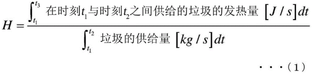
算式(1)的分母是在时刻t1至时刻t2之间供给的垃圾的质量[kg]。分子表示时刻t1至时刻t2之间供给的垃圾的发热量[J]。分母的积分区间、起始点t1与终点t2的时间差例如可以是1分钟以下。然而,分子的积分区间、起始点t1与终点t3的时间差不一定能那样处理。就煤粉、石油、可燃气体而言,一对炉供给就立刻燃尽,因此分子的积分区间的终点t3可以与作为分母的积分区间的终点的t2是相同程度,因此,能不延迟地例如在1分钟以内计算低位发热量。若供给后立刻燃尽,则在分子的计算中,区分供给的垃圾何时实现发热并不重要,因此能允许假设t3=t2,简单地将时刻t1至时刻t2的总发热设为由相同时刻供给的垃圾而实现的发热量。然而,垃圾与煤粉等不同,至燃尽为止需要1小时以上,因此作为发热量的积分的终点的t3必须设为比t2长至少1小时左右。因此,就算式(1)的分子的计算而言,至少需要至燃尽为止的时间(例如1小时左右)的长期的数据。然而,通过计算而获知的是1小时前供给的垃圾的低位发热量。即使已知1小时前的低位发热量,对实时的控制不太起作用。The denominator of the formula (1) is the mass [kg] of the garbage supplied between time t1 and time t2 . The numerator represents the calorific value [J] of the garbage supplied between time t1 and time t2 . The integration interval of the denominator and the time difference between the start point t1 and the end point t2 may be, for example, 1 minute or less. However, the integration interval of the molecule and the time difference between the start point t1 and the end point t3 may not necessarily be handled in this way. As far as pulverized coal, petroleum, and combustible gas are concerned, the supply of a pair of furnaces will be burned immediately, so the end point t3 of the integral interval of the numerator can be the same as t2 , the end point of the integral interval of the denominator, so there can be no delay For example, calculate the low calorific value within 1 minute. If it burns immediately after being supplied, in the calculation of the molecule, it is not important to distinguish when the supplied garbage realizes heat generation, so it is allowed to assume t 3 =t 2 , and simply set the total heat generation from time t 1 to time t 2 Calorific value achieved for garbage supplied at the same time. However, unlike pulverized coal, garbage takes more than one hour to burn out, so t3 , which is the end point of calorific value integration, must be set at least about one hour longer than t2 . Therefore, even the calculation of the numerator of the formula (1) requires long-term data of at least the time until burnout (for example, about 1 hour). However, what is known by calculation is the low calorific value of the garbage supplied one hour ago. Even if the low calorific value 1 hour ago is known, it is not very effective for real-time control.

实际上,滞后不止1小时。以下,对该时间滞后进行说明。时刻t1至时刻t3的发热量包括:时刻t1以前供给并且已经位于炉内的垃圾的发热量;以及时刻t2以后已供给的垃圾的发热量,因此,在算式(1)的分子的计算中,必须仅将由在时刻t1与时刻t2之间供给的垃圾而实现的发热从垃圾的发热的中分出来计算,这是很困难的。因此,若简单地对发热量进行积分,则分母的发热量是时刻t1至时刻t3的总发热量,与此相对分子的供给量不限于时刻t1至t2的供给量,因此低位发热量过大。例如,当设定t1=0、t2=1分钟,假设至燃尽为止花费60分钟,t3=61分钟时,若简单地对发热量进行积分,则低位发热量约为实际的60倍的值。为了防止这种情况,将分母的积分区间设为垃圾至燃尽为止的时间的几倍长,使t2与t3的值接近是有效的。例如,若t1=0、t2=300分钟、t3=360分钟,则低位发热量是实际的值的1.2倍,可能会成为较好的近似。然而,用该方法获得的低位发热量的值在时间上进一步滞后,是将长时间的发热量平均化,而不是当时的及时的发热量。如此,低位发热量的推定值在原理上伴随着几小时的滞后和平均化,对燃烧状态急速变化时的运转操作不起作用。Actually, the lag is more than 1 hour. Hereinafter, this time lag will be described. The calorific value from time t1 to time t3 includes: the calorific value of the garbage supplied before time t1 and already in the furnace; and the calorific value of the garbage supplied after time t2 . In the calculation of , it is necessary to separate only the heat generated by the garbage supplied between time t1 and time t2 from the heat generated by the garbage, which is very difficult. Therefore, if the calorific value is simply integrated, the calorific value of the denominator is the total calorific value from time t1 to time t3 , while the supply amount of the numerator is not limited to the supply amount from time t1 to t2 , so the lower Excessive heat generation. For example, when setting t 1 =0, t 2 =1 minute, assuming that it takes 60 minutes to burn out, and t 3 =61 minutes, if the calorific value is simply integrated, the low calorific value is about 60 times the value. In order to prevent this, it is effective to set the integral interval of the denominator to be several times longer than the time until the garbage is burned, and to make the values of t2 and t3 close. For example, if t 1 =0, t 2 =300 minutes, and t 3 =360 minutes, the low-level calorific value is 1.2 times the actual value, which may be a good approximation. However, the value of the lower calorific value obtained by this method is further delayed in time, and the calorific value is averaged over a long period of time, rather than the real calorific value at that time. In this way, the estimated value of the low-level calorific value is in principle accompanied by a lag and averaging of several hours, and has no effect on the operation when the combustion state changes rapidly.

现有技术文献prior art literature

专利文献patent documents

专利文献1:日本特开2019-178850号公报Patent Document 1: Japanese Patent Laid-Open No. 2019-178850

专利文献2:日本专利第5996762号公报Patent Document 2: Japanese Patent No. 5996762

专利文献3:日本专利第3822328号公报Patent Document 3: Japanese Patent No. 3822328

专利文献4:日本实开昭63-61621号公报Patent Document 4: Japanese Publication No. 63-61621

发明内容Contents of the invention

发明要解决的问题The problem to be solved by the invention

提供一种早期地检测垃圾焚烧炉的燃烧的变动,并且抑制该变动的控制方法。Provided is a control method for detecting fluctuations in combustion in a waste incinerator at an early stage and suppressing the fluctuations.

本发明提供一种能解决上述问题的控制装置、垃圾焚烧设备、控制方法以及程序。The present invention provides a control device, waste incineration equipment, control method and program capable of solving the above problems.

技术方案Technical solutions

本发明的控制装置具备:数据获取部,获取垃圾焚烧设备所具备的传感器计测到的计测值;燃烧速度推定部,使用所述计测值来推定所述垃圾焚烧设备的焚烧炉中的燃烧速度;以及控制部,基于所述燃烧速度来控制垃圾的供给量或者对所述焚烧炉供给的燃烧空气的流量。The control device of the present invention includes: a data acquisition unit that acquires a measurement value measured by a sensor included in the garbage incineration facility; a combustion rate; and a control unit for controlling a supply amount of garbage or a flow rate of combustion air supplied to the incinerator based on the combustion rate.

此外,本发明的控制方法包括:获取垃圾焚烧设备所具备的传感器计测到的计测值的步骤;使用所述计测值来推定所述垃圾焚烧设备的焚烧炉中的燃烧速度的步骤;以及基于所述燃烧速度来控制垃圾的供给量或者对所述焚烧炉供给的燃烧空气的流量的步骤。In addition, the control method of the present invention includes: a step of acquiring a measured value measured by a sensor included in the waste incineration facility; and a step of estimating a combustion rate in an incinerator of the waste incineration facility using the measured value; and a step of controlling the supply amount of refuse or the flow rate of combustion air supplied to the incinerator based on the combustion rate.

此外,本发明的垃圾焚烧设备具备:焚烧炉,焚烧垃圾;垃圾给料装置,对所述焚烧炉供给垃圾;送风机,对所述焚烧炉供给燃烧空气;燃烧空气阀门,控制从所述送风机向所述焚烧炉供给的燃烧空气的流量;以及上述的控制装置。In addition, the garbage incineration equipment of the present invention includes: an incinerator for burning garbage; a garbage feeding device for supplying garbage to the incinerator; a blower for supplying combustion air to the incinerator; and a combustion air valve for controlling the flow from the blower to the incinerator. The flow rate of the combustion air supplied by the incinerator; and the above-mentioned control device.

此外,本发明的程序使计算机执行:获取垃圾焚烧设备所具备的传感器计测的计测值的步骤;使用所述计测值来推定所述垃圾焚烧设备的焚烧炉中的燃烧速度的步骤;以及基于所述燃烧速度来控制垃圾的供给量或者对所述焚烧炉供给的燃烧空气的流量的步骤。In addition, the program of the present invention causes the computer to execute: the steps of acquiring a measured value measured by a sensor included in the waste incineration facility; and the step of estimating the combustion rate in the incinerator of the waste incineration facility using the measured value; and a step of controlling the supply amount of refuse or the flow rate of combustion air supplied to the incinerator based on the combustion rate.

发明效果Invention effect

根据上述的控制装置、垃圾焚烧设备、控制方法以及程序,能抑制垃圾焚烧设备的燃烧的变动。According to the control device, waste incinerator, control method, and program described above, it is possible to suppress fluctuations in combustion of the waste incinerator.

附图说明Description of drawings

图1是表示各实施方式的垃圾焚烧设备的一个例子的图。FIG. 1 is a diagram showing an example of a waste incineration facility according to each embodiment.

图2是表示第一实施方式的控制装置的主要部分的功能构成的一个例子的图。FIG. 2 is a diagram showing an example of a functional configuration of a main part of the control device according to the first embodiment.

图3是表示第一实施方式的控制装置的动作的一个例子的图。FIG. 3 is a diagram showing an example of the operation of the control device according to the first embodiment.

图4是表示第二实施方式的控制装置的主要部分的功能构成的一个例子的图。4 is a diagram showing an example of a functional configuration of a main part of a control device according to a second embodiment.

图5是表示第二实施方式的控制装置的动作的一个例子的图。FIG. 5 is a diagram showing an example of the operation of the control device according to the second embodiment.

图6是表示第三实施方式的控制装置的主要部分的功能构成的一个例子的图。6 is a diagram showing an example of a functional configuration of a main part of a control device according to a third embodiment.

图7是表示第三实施方式的控制装置的动作的一个例子的图。FIG. 7 is a diagram showing an example of the operation of the control device according to the third embodiment.

图8是表示第四实施方式的控制装置的主要部分的功能构成的一个例子的图。8 is a diagram showing an example of a functional configuration of a main part of a control device according to a fourth embodiment.

图9是表示第五实施方式的控制装置的主要部分的功能构成的一个例子的图。9 is a diagram showing an example of a functional configuration of a main part of a control device according to a fifth embodiment.

图10是表示第五实施方式的控制装置的动作的一个例子的图。FIG. 10 is a diagram showing an example of the operation of the control device according to the fifth embodiment.

图11是表示第六实施方式的控制装置的主要部分的功能构成的一个例子的图。11 is a diagram showing an example of a functional configuration of a main part of a control device according to a sixth embodiment.

图12是表示第六实施方式的控制装置的动作的一个例子的图。FIG. 12 is a diagram showing an example of the operation of the control device according to the sixth embodiment.

图13是表示各实施方式的控制装置的硬件构成的一个例子的图。FIG. 13 is a diagram showing an example of a hardware configuration of a control device according to each embodiment.

具体实施方式detailed description

以下,参照附图对实施方式的垃圾焚烧设备进行说明。在以下的说明中,对具有相同或者类似的功能的构成附加相同的符号。并且,有时会省略其构成的重复的说明。“XX或者YY”是指,不限于XX和YY中的任一方的情况,也可以包括XX和YY两方的情况。这在选择性元素为三个以上的情况下也是同样的。“XX”和“YY”是任意的元素(例如任意的信息)。Hereinafter, a waste incineration facility according to an embodiment will be described with reference to the drawings. In the following description, components having the same or similar functions are denoted by the same reference numerals. Also, overlapping descriptions of the configurations may be omitted. "XX or YY" is not limited to any one of XX and YY, and may include both XX and YY. This also applies to the case where there are three or more optional elements. "XX" and "YY" are arbitrary elements (for example, arbitrary information).

(系统构成)(System Components)

图1是表示各实施方式的垃圾焚烧设备的一个例子的图。FIG. 1 is a diagram showing an example of a waste incineration facility according to each embodiment.

垃圾焚烧设备100具备:料斗1,供垃圾投入;滑槽2,将投入至料斗1的垃圾向下部引导;推送器10,将通过滑槽2而供给的垃圾向燃烧室6内供给;炉排3,接受由推送器10供给的垃圾,移送垃圾的同时进行干燥和燃烧;燃烧室6,燃烧垃圾;灰出口7,排出灰;送风机4,供给空气;多个风箱5A~5E,将由送风机4供给的空气向炉排3的各部引导;管路14,将由送风机4供给的空气向燃烧室6直接供给;以及锅炉9。The garbage incineration facility 100 is equipped with: a hopper 1 for feeding garbage; a chute 2 for guiding the garbage thrown into the hopper 1 to the lower part; a pusher 10 for feeding the garbage supplied through the chute 2 into the combustion chamber 6; 3. Receive the garbage supplied by the pusher 10, dry and burn while transferring the garbage; combustion chamber 6, burn garbage; ash outlet 7, discharge ash; blower 4, supply air; The supplied air is guided to each part of the grate 3 ; the duct 14 directly supplies the air supplied by the blower 4 to the combustion chamber 6 ; and the boiler 9 .

推送器10是一种垃圾给料装置,在箭头α的方向上移动,将通过滑槽2而供给的垃圾推出,从而将垃圾向炉排3供给。炉排3设置于滑槽2和燃烧室6的底部并输送垃圾。炉排3具备:干燥区3A,使由推送器10供给的垃圾的水分蒸发并干燥;燃烧区3B,位于干燥区3A的下游,使干燥的垃圾燃烧;以及后燃烧区3C,位于燃烧区3B的下游,使未燃烧而通过的固定碳成分等未燃成分燃烧至成灰。接收来自控制装置20的控制信号,控制炉排3的动作速度。The pusher 10 is a garbage feeding device, which moves in the direction of the arrow α to push out the garbage supplied through the chute 2 , so as to supply the garbage to the grate 3 . Fire grate 3 is arranged on the bottom of chute 2 and combustion chamber 6 and transports garbage. The grate 3 is provided with: a drying zone 3A for evaporating and drying the moisture of the refuse supplied by the pusher 10; a burning zone 3B located downstream of the drying zone 3A for burning the dried refuse; and a post-combustion zone 3C located in the burning zone 3B Downstream, unburned components such as fixed carbon components passing through without burning are burned to ash. Receive the control signal from the control device 20 to control the motion speed of the grate 3 .

送风机4设置于炉排3的下方,通过风箱5A~5E将空气向炉排3的各部供给。在将送风机4输送的空气向风箱5A~5E引导的管路8F上连接有分别将管路8F与风箱5A~5E连接的支管,支管上各自设有阀门8A~8E,能通过调节阀门8A~8E的开度,从而调节向风箱5A~5E供给的燃烧空气的流量。接收来自控制装置20的控制信号、控制送风机4的送风量、阀门8A~8E的开度。有时统称阀门8A~8E记载为一次燃烧空气阀门。The air blower 4 is installed below the grate 3, and supplies air to each part of the grate 3 through the bellows 5A-5E. On the pipeline 8F that guides the air delivered by the blower 4 to the bellows 5A~5E, there are branch pipes that connect the pipeline 8F and the bellows 5A~5E respectively. 8E to adjust the flow rate of the combustion air supplied to the wind boxes 5A-5E. The control signal from the control device 20 is received to control the blowing volume of the blower 4 and the opening degrees of the valves 8A to 8E. Valves 8A to 8E are sometimes collectively referred to as primary combustion air valves.

燃烧室6在炉排3的上方由一次燃烧室6A和二次燃烧室6B构成,锅炉9配设于燃烧室6的下游。一次燃烧室6A设于炉排3的上方,一次燃烧室6A的更上方设有二次燃烧室6B。在一次燃烧室6A中,使由垃圾产生的热分解气体燃烧,在一次燃烧室6A燃烧残留的未燃成分的热分解气体被送至二次燃烧室6B,在二次燃烧室与二次燃烧空气混合使未燃成分也燃烧。在燃烧室6的二次燃烧室6B连接有连接送风机4和二次燃烧室6B的管路14,能通过设于管路14的阀门14A的开闭,从而向燃烧室6供给空气。接收来自控制装置20的控制信号,控制阀门14A的开度。有时将阀门14A记载为二次燃烧空气阀门。锅炉9使从燃烧室6送出的排气与在锅炉9内循环的水进行热交换而产生蒸汽。蒸汽通过管路13向未图示的发电用的涡轮机供给。在管路13设有检测蒸汽的流量的蒸汽流量传感器11。蒸汽流量传感器11与控制装置20连接,将蒸汽流量传感器11计测到的计测值向控制装置20发送。The combustion chamber 6 is composed of a primary combustion chamber 6A and a secondary combustion chamber 6B above the grate 3 , and the boiler 9 is arranged downstream of the combustion chamber 6 . The primary combustion chamber 6A is provided above the grate 3, and the secondary combustion chamber 6B is provided above the primary combustion chamber 6A. In the primary combustion chamber 6A, the pyrolysis gas produced by the garbage is combusted, and the pyrolysis gas of the unburned components remaining after combustion in the primary combustion chamber 6A is sent to the secondary combustion chamber 6B, where the secondary combustion chamber and the secondary combustion Air mixing causes the unburned components to also burn. A pipe 14 connecting the blower 4 and the secondary combustion chamber 6B is connected to the secondary combustion chamber 6B of the combustion chamber 6 , and air can be supplied to the combustion chamber 6 by opening and closing a valve 14A provided on the pipe 14 . The opening degree of the valve 14A is controlled by receiving a control signal from the control device 20 . The valve 14A is sometimes described as a secondary combustion air valve. The boiler 9 generates steam by exchanging heat between the exhaust gas sent from the combustion chamber 6 and the water circulating in the boiler 9 . The steam is supplied to a turbine for power generation (not shown) through a line 13 . A steam flow sensor 11 for detecting the flow rate of steam is provided in the pipeline 13 . The steam flow sensor 11 is connected to the control device 20 , and transmits the measured value measured by the steam flow sensor 11 to the control device 20 .

在锅炉9的排气出口连接有烟道12,用锅炉9进行了热回收的排气穿过烟道12并穿过未图示的排气处理设备后,排出至外部。A flue 12 is connected to an exhaust outlet of the boiler 9 , and the exhaust gas that has been heat recovered by the boiler 9 passes through the flue 12 and exhaust gas treatment equipment (not shown) before being discharged to the outside.

在烟道12设有检测排气的氧气浓度的氧气浓度传感器15。氧气浓度传感器15与控制装置20连接,氧气浓度传感器15计测的计测值被发送向控制装置20。在锅炉第二通道设有计测第二通道的温度的温度传感器17A,在烟道12设有:CO浓度传感器17B,计测排气的CO浓度;以及NOx浓度传感器17C,检测排气的NOx浓度。这些传感器17A~17C各自与控制装置20连接,传感器17A~17C计测的计测值被发送向控制装置20。此外,在管路8F设有检测通过风箱5A~5E向一次燃烧室6A供给的一次燃烧空气的流量的流量传感器17D,在管路14设有检测向二次燃烧室6B供给的二次燃烧空气的流量的流量传感器17E。这些传感器17D~17E与控制装置20连接,流量传感器17D~17E计测的计测值被发送向控制装置20。在燃烧室6设有计测燃烧室6内的温度的温度传感器16。温度传感器16与控制装置20连接,温度传感器16计测的计测值被发送向控制装置20。这些传感器是通常的垃圾焚烧发电设备中设有的传感器。The flue 12 is provided with an oxygen concentration sensor 15 for detecting the oxygen concentration of the exhaust gas. The oxygen concentration sensor 15 is connected to the control device 20 , and the measured value measured by the oxygen concentration sensor 15 is sent to the control device 20 . A temperature sensor 17A for measuring the temperature of the second channel is installed in the second channel of the boiler, and a CO concentration sensor 17B is installed in the flue 12 to measure the CO concentration of the exhaust gas; and a NOx concentration sensor 17C is installed to detect the NOx of the exhaust gas concentration. Each of these sensors 17A to 17C is connected to the control device 20 , and the measured values measured by the sensors 17A to 17C are sent to the control device 20 . In addition, a flow sensor 17D for detecting the flow rate of the primary combustion air supplied to the primary combustion chamber 6A through the wind boxes 5A to 5E is provided in the pipe line 8F, and a flow sensor 17D for detecting the flow rate of the secondary combustion air supplied to the secondary combustion chamber 6B is provided in the pipe line 14 . The flow rate of the flow sensor 17E. These sensors 17D to 17E are connected to the control device 20 , and the measured values measured by the flow rate sensors 17D to 17E are sent to the control device 20 . The combustion chamber 6 is provided with a temperature sensor 16 for measuring the temperature in the combustion chamber 6 . The temperature sensor 16 is connected to the control device 20 , and the measured value measured by the temperature sensor 16 is sent to the control device 20 . These sensors are sensors provided in general waste incineration power generation facilities.

控制装置20具备数据获取部21、燃烧速度推定部22、控制部23以及存储部24。The control device 20 includes a data acquisition unit 21 , a combustion rate estimation unit 22 , a control unit 23 , and a storage unit 24 .

数据获取部21获取各传感器11、15、16、17A~17D计测到的计测值、用户的指示值等各种数据。例如,数据获取部21获取蒸汽流量传感器11计测到的蒸汽流量的计测值。The data acquisition part 21 acquires various data, such as the measured value measured by each sensor 11, 15, 16, 17A-17D, and the instruction|indication value of a user. For example, the data acquisition unit 21 acquires a measured value of the steam flow rate measured by the steam flow rate sensor 11 .

燃烧速度推定部22计算燃烧室6(以下,有时记载为炉)中的垃圾的燃烧速度。如专利文献4所公开的那样,在炉的发热量降低的原因中存在以下相反的原因:(a)燃烧的垃圾在炉内变少了的情况(燃料不足);以及(b)由于供给的垃圾而导致火焰熄灭的情况(燃料过量)。当发热量降低时,蒸汽流量传感器11计测的蒸汽流量也降低,因此蒸汽流量的降低也是由于(a)和(b)相反的原因。在以往的燃烧控制中,有时为了对(a)的燃料不足进行补偿,连续性地持续进行垃圾供给导致原因成为(b),发热量会越来越下降(逆响应)。因此,以往方式的机械设备中,若发热量降低的时间在一定程度长期的范围内一直持续则发出警报,进行由操作员进行的原因的推定和用于消除原因的恢复操作等的对应。与此相对,在本发明中,通过燃烧速度推定部22,基于蒸汽流量、燃烧室温度、排气气体中的氧气浓度等的“已经设置的”传感器(依次为蒸汽流量传感器11、温度传感器16、氧气浓度传感器15)来实时地推定炉整体的垃圾的燃烧难度,即在炉内发生的每单位时间的燃烧,换而言之燃烧速度,将推定出的燃烧速度用于燃烧空气的供给量、垃圾的供给量的计算。如后述的那样,在本发明的垃圾供给量的控制中,以通过反馈控制来抑制蒸汽流量的变动的方式确定垃圾供给量。此时,使指令垃圾供给量的反馈控制器的设定值适应于推定出的燃烧速度。具体而言,例如,垃圾难燃的情况(燃烧速度小)相当于(b),因此减小反馈增益,避免过量供给。若是除此以外的情况,则相当于(a),因此将反馈增益设为正常值。由此,能适当地应对(a)、(b)各自的发热量的降低。The combustion rate estimation part 22 calculates the combustion rate of the garbage in the combustion chamber 6 (it may describe below as a furnace). As disclosed in Patent Document 4, there are the following opposite reasons in the cause of the reduction in the calorific value of the furnace: (a) the situation that the burning garbage decreases in the furnace (insufficient fuel); A situation where the flame goes out due to garbage (excess fuel). When the calorific value decreases, the steam flow rate measured by the steam flow sensor 11 also decreases, so the decrease in the steam flow rate is also due to the opposite causes of (a) and (b). In the conventional combustion control, in order to compensate for the lack of fuel in (a), the continuous supply of garbage may cause (b) and the calorific value will gradually decrease (reverse response). Therefore, in conventional mechanical equipment, if the calorific value reduction continues for a certain long-term range, an alarm is issued, and the operator performs a response such as estimation of the cause and recovery operation for eliminating the cause. In contrast, in the present invention, the combustion velocity estimation unit 22 is based on "pre-installed" sensors (steam flow rate sensor 11, temperature sensor 16, etc.) of steam flow rate, combustion chamber temperature, and exhaust gas concentration , Oxygen concentration sensor 15) to estimate in real time the difficulty of burning the garbage in the furnace as a whole, that is, the combustion per unit time that occurs in the furnace, in other words, the combustion speed, and use the estimated combustion speed for the supply amount of combustion air , Calculation of the supply of garbage. As will be described later, in the control of the garbage supply amount in the present invention, the garbage supply amount is determined so as to suppress fluctuations in the steam flow rate by feedback control. At this time, the set value of the feedback controller of the commanded waste supply amount is adapted to the estimated combustion rate. Specifically, for example, when the garbage is difficult to burn (the burning speed is small), it corresponds to (b), so the feedback gain is reduced to avoid oversupply. Otherwise, it corresponds to (a), so the feedback gain is set to a normal value. Accordingly, it is possible to appropriately cope with the reductions in the respective calorific values of (a) and (b).

为了使燃烧速度的推定结果按照意图发挥功能,重要的是尽快地推定垃圾的燃烧速度。如使用专利文献2、3来进行说明的那样,垃圾的每单位供给量的发热量(低位发热量)的推定存在原理上的问题。因此,在本发明中将燃烧速度设为指标来代替低位发热量。低位发热量为供给的垃圾的每单位质量的发热量,与此相对,燃烧速度表示炉整体的发热,无关位于炉内的垃圾的质量。此外,燃烧速度不限于炉内的垃圾的燃烧还包括热分解气体的燃烧。按照前述,在垃圾焚烧设备100中,垃圾被投入至燃尽花费时间,因此在炉内存在大量的垃圾的蓄积。其蓄积的燃烧速度就炉整体而言几乎是固定值但是会呈时间性地变动,其结果是,蒸汽流量传感器11计测的蒸汽流量变动。燃烧速度的变动的原因是多样的:新供给的垃圾所含水分多从而妨碍周围的燃烧、燃烧空气的供给由于垃圾层的崩坏等而改变等。燃烧速度的变动除了蒸汽流量以外也表现于垃圾焚烧设备100的计测值(上述的燃烧室温、排气气体中的氧气浓度等)。在本发明中,根据现有的传感器而实现的计测值实时地推定炉内的燃烧速度。In order for the estimation result of the burning rate to function as intended, it is important to estimate the burning rate of the garbage as quickly as possible. As described using Patent Documents 2 and 3, the estimation of the calorific value (lower calorific value) per unit supply amount of garbage has a problem in principle. Therefore, in the present invention, the combustion rate is used as an index instead of the low calorific value. The lower calorific value is the calorific value per unit mass of the supplied garbage, whereas the combustion rate represents the heat generated by the furnace as a whole, regardless of the mass of the garbage in the furnace. In addition, the combustion rate is not limited to the combustion of waste in the furnace but also includes the combustion of pyrolysis gas. As described above, in the garbage incineration facility 100, it takes time until the garbage is thrown in and burnt out, so a large amount of garbage accumulates in the furnace. The accumulated combustion rate is almost a constant value for the entire furnace but fluctuates temporally. As a result, the steam flow rate measured by the steam flow sensor 11 fluctuates. There are various reasons for the fluctuation of the combustion rate: newly supplied garbage contains a lot of water, which hinders the surrounding combustion, and the supply of combustion air changes due to the collapse of the garbage layer, etc. The fluctuation of the combustion rate is also expressed in the measured values of the waste incinerator 100 (the above-mentioned combustion room temperature, the oxygen concentration in the exhaust gas, etc.) in addition to the steam flow rate. In the present invention, the combustion rate in the furnace is estimated in real time from measured values obtained by conventional sensors.

(燃烧速度的推定顺序)(Estimated order of burning rate)

在垃圾焚烧设备100中,垃圾的燃烧速度不断地变动,这是无法避免的。在垃圾焚烧设备100中,即使供给的垃圾的一部分瞬时燃烧,大部分作为可燃物蓄积在炉的炉排3之上,从干燥了的部分起按顺序燃烧。例如,假设存在已干燥的垃圾的块,其表面正在燃烧。此时,炉排3进行动作等使垃圾的块破裂,若产生新的与燃烧空气接触的表面,则在此处开始新的燃烧,炉整体的燃烧速度增大。反之,在其表面覆盖含水分多的垃圾,温度下降,或者,若中断燃烧空气的供给等,则阻碍燃烧,炉整体的燃烧速度减小。在垃圾焚烧设备100中,像这样的燃烧速度的变动不断地发生。与此对照,就煤粉的燃烧、石油或者天然气体而言,一对炉供给就瞬间燃尽,因此若供给流量固定则燃烧速度也固定。In the waste incineration facility 100, the burning speed of the waste constantly fluctuates, which cannot be avoided. In the refuse incinerator 100, even if a part of the supplied refuse is burnt instantly, most of it is accumulated as combustibles on the grate 3 of the furnace, and burnt sequentially from the dried part. For example, suppose there is a block of dried trash whose surface is burning. At this time, the fire grate 3 is operated to break the lumps of garbage, and if a new surface comes into contact with the combustion air, new combustion will start there, and the combustion speed of the entire furnace will increase. Conversely, if the surface is covered with moisture-rich garbage, the temperature will drop, or if the supply of combustion air is interrupted, the combustion will be hindered, and the combustion speed of the entire furnace will decrease. In the waste incineration facility 100, such fluctuations in the combustion rate are constantly occurring. In contrast, in the combustion of pulverized coal, oil, or natural gas, a pair of furnace supplies burns out instantly, so if the supply flow rate is constant, the combustion rate is also constant.

由于燃烧速度q的变动,垃圾焚烧设备100的计测值y也变动。用线性算式将两者的变动近似为算式(2)。The measured value y of the waste incinerator 100 also fluctuates due to fluctuations in the combustion rate q. The changes of the two are approximated as formula (2) with a linear formula.

y=c1×q···(2)y=c 1 ×q···(2)

以下,假设计测值y是蒸汽流量、燃烧室温度、排气气体的氧气浓度,进行具体的说明。这些是一个例子,也可以是锅炉的第二通道温度、排气的NOx浓度、排气的CO浓度、一次燃烧空气流量、二次燃烧空气流量等。算式(2)的c1是3行1列的系数向量。c1表示燃烧速度增加时的计测值y,即蒸汽流量、燃烧室温度、排气气体的氧气浓度的变动。若燃烧量增加,则蒸汽流量增加,燃烧室温度增加,排气的氧气浓度减少。c1是量化增大、减小的系数向量。Hereinafter, a concrete description will be given assuming that the measured value y is the steam flow rate, the combustion chamber temperature, and the oxygen concentration of the exhaust gas. These are just an example, and may be the second pass temperature of the boiler, the NOx concentration of the exhaust gas, the CO concentration of the exhaust gas, the primary combustion air flow rate, the secondary combustion air flow rate, and the like. c 1 in the formula (2) is a coefficient vector of 3 rows and 1 column. c1 represents the measured value y when the combustion rate increases, that is, the variation of the steam flow rate, the temperature of the combustion chamber, and the oxygen concentration of the exhaust gas. If the combustion amount increases, the steam flow rate increases, the temperature of the combustion chamber increases, and the oxygen concentration of the exhaust gas decreases. c 1 is the coefficient vector of quantization increase and decrease.

算式(2)根据燃烧速度q的变动给予计测值y变动,但无法直接倒算燃烧速度q。以下,对根据计测值y的变动推定燃烧速度的方法进行描述。首先,构成以蒸汽流量、燃烧室温度、排气气体的氧气浓度等计测值为列元素的计测值向量y,如算式(3)那样求取方差协方差矩阵Q0。Var(y)表示向量y的方差协方差矩阵。Equation (2) varies the measured value y according to the variation of the combustion rate q, but the combustion rate q cannot be directly calculated backward. Hereinafter, a method of estimating the combustion rate from fluctuations in the measured value y will be described. First, a measured value vector y having measured values such as steam flow rate, combustion chamber temperature, and exhaust gas oxygen concentration is constructed as column elements, and a variance-covariance matrix Q 0 is obtained as in Equation (3). Var(y) represents the variance-covariance matrix of the vector y.

Q0=Var(y)···(3)Q 0 =Var(y)···(3)

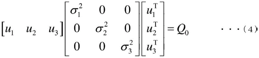
接着,对方差协方差矩阵Q0进行奇异值分解,求取算式(4)的奇异向量ui(i=1、2、3)和奇异值σ2 i(i=1、2、3)。在此按照奇异值分解的惯例,奇异值按照大小的顺序排序。即σ2 1为最大奇异值,σ2 3为最小奇异值。右肩的记号T表示矩阵或者向量的转置。Next, perform singular value decomposition on the variance-covariance matrix Q 0 to obtain the singular vector u i (i=1, 2, 3) and singular value σ 2 i (i=1, 2, 3) in formula (4). Here, following the convention of singular value decomposition, the singular values are sorted in order of magnitude. That is, σ 2 1 is the largest singular value, and σ 2 3 is the smallest singular value. The notation T on the right shoulder indicates the transpose of a matrix or vector.

[数式2][Formula 2]

Figure BDA0003595761270000111

接着,假设未知的外部干扰ρ存在,如以下的算式(5)那样,用奇异向量u和未知的外部干扰ρ表示计测值y的变动。未知的外部干扰ρ包括作为分量的算式(2)的燃烧速度的变动q,但实际情况尚不清楚。以下,对两者的关系进行说明。u的值是通过对计测值向量y的方差协方差矩阵Q0进行奇异值分解来确定的。假设计测值向量y由于未知的外部干扰ρ而变动,如算式(5)那样,用ρ的线性组合表示计测值向量y。将ρ的元素表示为ρi(i=1、2、3)。Next, assuming that an unknown external disturbance ρ exists, the variation of the measured value y is represented by the singular vector u and the unknown external disturbance ρ as in the following formula (5). The unknown external disturbance ρ includes as a component the variation q of the combustion rate in equation (2), but the actual situation is not clear. Hereinafter, the relationship between both will be described. The value of u is determined by performing singular value decomposition on the variance-covariance matrix Q 0 of the measured value vector y. Assuming that the measured value vector y fluctuates due to an unknown external disturbance ρ, the measured value vector y is represented by a linear combination of ρ as in Equation (5). The elements of ρ are denoted as ρi (i=1, 2, 3).

[数式3][Formula 3]

Figure BDA0003595761270000112

由于方差协方差矩阵Q0的对称性,因此奇异向量u具有算式(6)的性质。Due to the symmetry of the variance covariance matrix Q 0 , the singular vector u has the property of formula (6).

[数式4][Formula 4]

Figure BDA0003595761270000121

因此,根据算式(5)和算式(6),像算式(5A)那样直接确定ρ的值。Therefore, the value of ρ is directly determined as in the formula (5A) from the formula (5) and the formula (6).

[数式5][Formula 5]

Figure BDA0003595761270000122

ρ的方差协方差矩阵为算式(7)。The variance covariance matrix of ρ is formula (7).

[数式6][Formula 6]

Figure BDA0003595761270000123

如算式(7)所示,作为未知的外部干扰的第一元素的ρ1的方差是最大奇异值σ1 2,因此计测值向量y的变动主要是由ρ1引起的。这是因为根据奇异值的性质,As shown in Equation (7), the variance of ρ 1 , which is the first element of the unknown external disturbance, is the largest singular value σ 1 2 , so fluctuations in the measured value vector y are mainly caused by ρ 1 . This is because according to the properties of singular values,

Var(y1)+Var(y2)+Var(y3)=σ1 22 23 2 μ···(8)Var(y1)+Var(y2)+Var(y3)=σ 1 22 23 2 μ ···(8)

成立,特别是当σ1 2>>σ2 23 2时,近似为下列算式(8A)。holds, especially when σ 1 2 >>σ 2 23 2 , it is approximated by the following formula (8A).

[数式7][Formula 7]

Figure BDA0003595761270000131

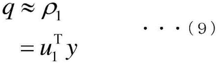
算式(8A)表示计测值向量y的变动受ρ1主导。另一方面,已知垃圾焚烧设备100的计测值的变动是根据燃烧速度的变动,因此将ρ1设为燃烧速度q的推定值是合理的。若从算式(5A)取出关于ρ1的计算的部分,则获得算式(9)作为燃烧速度的变动的推定式。根据算式(9),能基于计测值y来用较少的计算量迅速地计算燃烧速度q的推定值。Equation (8A) shows that the variation of the measured value vector y is dominated by ρ1. On the other hand, it is known that the fluctuation of the measured value of the waste incinerator 100 is due to the fluctuation of the combustion rate, so it is reasonable to set ρ1 as an estimated value of the combustion rate q. When the calculation of ρ1 is taken out from the formula (5A), the formula (9) is obtained as an estimation formula of the variation of the combustion rate. According to the formula (9), the estimated value of the combustion rate q can be quickly calculated based on the measured value y with a small amount of calculation.

[数式8][Formula 8]

Figure BDA0003595761270000132

如上所述,就燃烧速度q的推定而言,也可以使用锅炉第二通道温度、排气的CO浓度、排气的NOx浓度、一次燃烧空气流量、二次燃烧空气流量等来代替燃烧室温度、排气的氧气浓度、蒸汽流量,或者除了燃烧室温度、排气的氧气浓度、蒸汽流量以外,还可以使用锅炉第二通道温度、排气的CO浓度、排气的NOx浓度、一次燃烧空气流量、二次燃烧空气流量等。As described above, for estimating the combustion rate q, the temperature of the second passage of the boiler, the CO concentration of the exhaust gas, the NOx concentration of the exhaust gas, the flow rate of the primary combustion air, the flow rate of the secondary combustion air, etc. may be used instead of the combustion chamber temperature , exhaust oxygen concentration, steam flow, or in addition to combustion chamber temperature, exhaust oxygen concentration, steam flow, can also use boiler second channel temperature, exhaust CO concentration, exhaust NOx concentration, primary combustion air flow, secondary combustion air flow, etc.

上述的燃烧速度q的推定方法是一个例子,不限与此。例如,也可以使用神经网络、深度学习等方法来创建推定燃烧速度q的推定模型。The method of estimating the burning rate q described above is an example and is not limited thereto. For example, an estimation model for estimating the combustion rate q may be created using a method such as a neural network or deep learning.

控制部23控制垃圾焚烧设备100的动作。例如,在监测蒸汽流量传感器11计测的蒸汽流量等的同时,计算向燃烧室6的垃圾的供给量、向燃烧室6的燃烧空气的供给量,通过调整这些,进行垃圾的燃烧控制。具体而言,控制部23通过送风机4的转速、阀门8A~8E、阀门14A的开度控制,将所期望的量的燃烧空气向燃烧室6供给,并且通过推送器10的控制,将所期望的量的垃圾向燃烧室6供给。例如,基于蒸汽流量的计测值与设定值的偏差来计算垃圾的供给量,基于蒸汽流量的设定值来计算燃烧空气的供给量。在本发明中,除此以外,还考虑燃烧速度推定部22推定出的实时的燃烧速度q,计算垃圾的供给量、燃烧空气的供给量(第一实施方式~第六实施方式)。The control unit 23 controls the operation of the waste incinerator 100 . For example, while monitoring the steam flow rate measured by the steam flow sensor 11, the amount of garbage supplied to the combustion chamber 6 and the amount of combustion air supplied to the combustion chamber 6 are calculated, and by adjusting these, combustion control of garbage is performed. Specifically, the control unit 23 supplies a desired amount of combustion air to the combustion chamber 6 by controlling the rotation speed of the blower 4, the openings of the valves 8A to 8E, and the valve 14A, and supplies a desired amount of combustion air to the combustion chamber 6 by controlling the pusher 10. The amount of garbage is supplied to the combustion chamber 6. For example, the supply amount of garbage is calculated based on the deviation between the measured value of the steam flow rate and the set value, and the supply amount of combustion air is calculated based on the set value of the steam flow rate. In the present invention, in addition to this, the real-time combustion rate q estimated by the combustion rate estimation unit 22 is considered to calculate the supply amount of garbage and the supply amount of combustion air (first to sixth embodiments).

存储部24存储数据获取部21获取到的信息、控制所需要的信息,例如,蒸汽流量设定值SV等。The storage unit 24 stores information acquired by the data acquisition unit 21 and information required for control, for example, steam flow rate set value SV and the like.

<第一实施方式><First Embodiment>

使用图2对第一实施方式的垃圾焚烧设备100的控制进行说明。Control of the waste incineration facility 100 of the first embodiment will be described using FIG. 2 .

(构成)(constitute)

图2是表示第一实施方式的控制装置的主要部分的功能构成的一个例子的图。FIG. 2 is a diagram showing an example of a functional configuration of a main part of the control device according to the first embodiment.

图2示出控制装置20中的燃烧速度推定部22和控制部23的主要部分的构成。燃烧速度推定部22通过上述的顺序推定燃烧速度q。控制部23具备系数计算表231和PI控制器232。在存储部24记录有蒸汽流量的设定值SV。垃圾焚烧设备100以蒸汽流量传感器11计测的蒸汽流量为设定值SV的方式运转。FIG. 2 shows configurations of main parts of the combustion rate estimation unit 22 and the control unit 23 in the control device 20 . The combustion rate estimating unit 22 estimates the combustion rate q through the procedure described above. The control unit 23 includes a coefficient calculation table 231 and a PI controller 232 . The set value SV of the steam flow rate is recorded in the storage unit 24 . The refuse incinerator 100 is operated so that the steam flow rate measured by the steam flow sensor 11 becomes the set value SV.

控制部23根据燃烧速度q来改变给料控制的强度。例如,若PI控制器用于垃圾供给量的调节,则随着燃烧速度q变更比例增益的值。如图2的系数计算表231所示,预先设定增益可变化系数β作为燃烧速度q的函数。控制部23基于燃烧速度q并参照系数计算表231来获取与燃烧速度q对应的系数β。PI控制器232例如输入蒸汽流量(t/h)的设定值(目标值)SV以及由蒸汽流量传感器11实现的计测值PV,并且对其偏差进行PI运算(比例积分运算),输出垃圾供给量(m3/h)作为MV。此时,像下列算式(10)那样将通过PI控制的比例增益KP乘以增益可变化系数β来变更。The control unit 23 changes the intensity of the feed control according to the combustion rate q. For example, if the PI controller is used to adjust the amount of garbage supplied, the value of the proportional gain is changed according to the combustion speed q. As shown in the coefficient calculation table 231 of FIG. 2 , the gain variable coefficient β is preset as a function of the combustion speed q. The control unit 23 acquires the coefficient β corresponding to the combustion rate q by referring to the coefficient calculation table 231 based on the combustion rate q. The PI controller 232 inputs, for example, the set value (target value) SV of the steam flow rate (t/h) and the measured value PV realized by the steam flow sensor 11, and performs PI calculation (proportional integral calculation) on the deviation thereof, and outputs garbage The supply amount (m 3 /h) was taken as MV. In this case, the proportional gain K P controlled by PI is multiplied by the gain variable coefficient β to be changed as in the following formula (10).

[数式9][Formula 9]

Figure BDA0003595761270000151

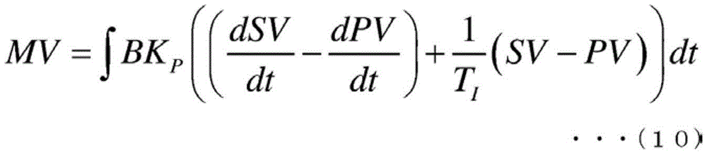
作为变更的方式,在当燃烧速度q小时,即难燃的情况(上述的(b))下,在炉内垃圾不燃烧而残留,因此不需要进一步追加垃圾。因此,例如将以与蒸汽流量偏差成比例的方式增加垃圾供给量的比例增益设为通常的一半。当在运转中变更PI控制器232的比例增益时,通常控制器用速度型的算法来实现。就PI控制器232而言,除了比例增益以外,积分时间常数TI也是调整常数。对积分时间常数TI而言,与比例增益同样地也可以随着燃烧速度q变更。控制部23基于PI控制器232输出的MV来控制推送器10的推出量。As a modification, when the combustion rate q is small, that is, when the combustion is difficult (the above-mentioned (b)), the garbage remains in the furnace without being burned, so it is not necessary to further add garbage. Therefore, for example, the proportional gain for increasing the refuse supply amount in proportion to the steam flow rate deviation is set to half of normal. When changing the proportional gain of the PI controller 232 during operation, the controller is usually implemented with a speed-type algorithm. As far as the PI controller 232 is concerned, besides the proportional gain, the integral time constant T I is also an adjustment constant. The integral time constant T I can also be changed according to the combustion speed q similarly to the proportional gain. The control unit 23 controls the pushing amount of the pusher 10 based on the MV output from the PI controller 232 .

(动作)(action)

接着,参照图3对第一实施方式的处理(垃圾供给量控制)的流程进行说明。Next, the flow of processing (garbage supply amount control) in the first embodiment will be described with reference to FIG. 3 .

图3是表示第一实施方式的控制装置的动作的一个例子的图。FIG. 3 is a diagram showing an example of the operation of the control device according to the first embodiment.

数据获取部21、燃烧速度推定部22以及控制部23以规定的时间间隔执行以下的处理。The data acquisition unit 21, the combustion rate estimation unit 22, and the control unit 23 execute the following processing at predetermined time intervals.

数据获取部21获取:蒸汽流量传感器11计测到的蒸汽流量PV;氧气浓度传感器15计测到的O2浓度;温度传感器16计测到的燃烧室6的温度;温度传感器17A计测到的锅炉第二通道的温度;CO浓度传感器17B计测到的排气的CO浓度;NOx浓度传感器17C计测到的排气的NOx浓度;流量传感器17D计测到的一次燃烧空气流量;流量传感器17E计测到的二次燃烧空气流量(步骤S1),并且将这些值向燃烧速度推定部22和控制部23输出。The data acquiring part 21 acquires: the steam flow PV measured by the steam flow sensor 11 ; the O concentration measured by the oxygen concentration sensor 15; the temperature of the combustion chamber 6 measured by the temperature sensor 16; the temperature measured by the temperature sensor 17A. The temperature of the second channel of the boiler; the CO concentration of the exhaust gas measured by the CO concentration sensor 17B; the NOx concentration of the exhaust gas measured by the NOx concentration sensor 17C; the primary combustion air flow rate measured by the flow sensor 17D; the flow sensor 17E The measured secondary combustion air flow rate is measured (step S1 ), and these values are output to the combustion rate estimation unit 22 and the control unit 23 .

燃烧速度推定部22使用蒸汽流量PV、氧气浓度、燃烧室温度、锅炉第二通道的温度、CO浓度传感器、NOx浓度、一次燃烧空气流量、二次燃烧空气流量中的优选多个(一个也可以)计测值y,通过算式(9),推定燃烧速度q(步骤S2)。燃烧速度推定部22将燃烧速度q向控制部23输出。The combustion rate estimation unit 22 uses preferably a plurality of steam flow rate PV, oxygen concentration, combustion chamber temperature, temperature of the boiler second pass, CO concentration sensor, NOx concentration, primary combustion air flow rate, and secondary combustion air flow rate (one may be used). ) measured value y, and the combustion rate q is estimated by formula (9) (step S2). The combustion rate estimation unit 22 outputs the combustion rate q to the control unit 23 .

接着控制部23基于燃烧速度q和系数计算表231来计算系数β。接着控制部23读出存储部24存储的蒸汽流量的设定值SV,并基于计算出的系数β、蒸汽流量的设定值SV、数据获取部21获取到的蒸汽流量PV以及算式(10)来计算垃圾供给量MV(步骤S3)。控制部23以能将垃圾供给量MV向炉内供给的方式控制推送器10的移动量(推出量)。Next, the control unit 23 calculates the coefficient β based on the combustion rate q and the coefficient calculation table 231 . Next, the control unit 23 reads out the set value SV of the steam flow rate stored in the storage unit 24, and based on the calculated coefficient β, the set value SV of the steam flow rate, the steam flow rate PV acquired by the data acquisition unit 21 and the formula (10) To calculate the garbage supply amount MV (step S3). The control part 23 controls the movement amount (extrusion amount) of the pusher 10 so that the refuse supply amount MV can be supplied into a furnace.

根据本实施方式,基于蒸汽流量、燃烧室温度、排气气体的氧气浓度等垃已经设置于圾焚烧设备100的传感器的计测值来推定炉整体的垃圾的燃烧速度,变更将蒸汽流量的设定值与计测值的偏差反馈给垃圾供给的PI控制器232的设定值(增益)。由此,能将向涡轮机的蒸汽流量均匀化,增加发电量,并使其稳定化。此外,通过燃烧室6的燃烧的稳定化,能抑制NOx、CO等的排出。According to this embodiment, the combustion rate of the garbage in the entire furnace is estimated based on the measured values of the sensors installed in the garbage incinerator 100 such as the steam flow rate, the temperature of the combustion chamber, and the oxygen concentration of the exhaust gas, and the setting of the steam flow rate is changed. The deviation between the fixed value and the measured value is fed back to the set value (gain) of the PI controller 232 for waste supply. Thereby, the flow rate of the steam to the turbine can be made uniform, and the amount of power generation can be increased and stabilized. In addition, by stabilizing the combustion in the combustion chamber 6, discharge of NOx, CO, and the like can be suppressed.

此外,根据本实施方式,(E1)根据蒸汽流量、燃烧室温度、排气气体的氧气浓度等已经设置于垃圾焚烧设备100的传感器(反映燃烧速度的变动的传感器)的计测值,推定垃圾的燃烧速度q,因此不必追加新的传感器。(E2)将依赖于垃圾供给量的发热量作为指标,并非着眼于作为发热量的变动原因的垃圾的水分等特定的元素,而将不依赖于垃圾供给量的燃烧速度设为指标,由此效果不限于对着眼的特定的元素,在由于各种各样的因素而燃烧状态变动的情况下,都能检测其变动,并与控制相结合(效果不限)。(E3)若将控制的指标设为垃圾供给量对应的发热量,则对发热量的推定会由于从垃圾供给至燃烧的时间差而产生误差,但在本发明中,将燃烧速度设为指标来代替发热量。发热量为供给的垃圾的每单位质量的发热量,与此相对,燃烧速度表示炉整体的发热,不依赖于位于炉内的垃圾的质量。由此,不会产生以发热量为控制指标时那样的误差的产生的情况。获得所述效果。In addition, according to the present embodiment, (E1) estimate the amount of waste generated from the measured values of the sensors (sensors that reflect changes in the combustion rate) already installed in the waste incinerator 100, such as the steam flow rate, the temperature of the combustion chamber, and the oxygen concentration of the exhaust gas, etc. The burning speed q, so there is no need to add a new sensor. (E2) Using the calorific value dependent on the amount of garbage supplied as an index, instead of focusing on specific elements such as moisture in the garbage that is the cause of fluctuations in the calorific value, and using the burning rate that does not depend on the amount of garbage supplied as an index, thereby The effect is not limited to the specific element in focus, and when the combustion state changes due to various factors, the change can be detected and combined with control (the effect is not limited). (E3) If the control index is set as the calorific value corresponding to the amount of garbage supplied, the estimation of the calorific value will have errors due to the time difference from garbage supply to combustion, but in the present invention, the burning speed is used as an index instead of heat. The calorific value is the calorific value per unit mass of the supplied garbage, whereas the combustion rate represents the calorific value of the entire furnace and does not depend on the mass of the garbage in the furnace. Thereby, occurrence of an error such as when the calorific value is used as a control index does not occur. achieve the effect described.

<第二实施方式><Second Embodiment>

使用图4、图5对第二实施方式的垃圾焚烧设备100的控制进行说明。The control of the waste incineration facility 100 of the second embodiment will be described using FIG. 4 and FIG. 5 .

(构成)(constitute)

图4是表示第二实施方式的控制装置的主要部分的功能构成的一个例子的图。4 is a diagram showing an example of a functional configuration of a main part of a control device according to a second embodiment.

图4示出控制装置20中的燃烧速度推定部22和控制部23A的主要部分的构成。燃烧速度推定部22通过上述的顺序推定燃烧速度q。控制部23A具备一次燃烧空气阀门的调整量计算表233以及加法器234。在存储部24记录有蒸汽流量的设定值SV以及作为与设定值SV相对的阀门8A~8E和阀门14A的基准的开度。FIG. 4 shows configurations of main parts of the combustion rate estimation unit 22 and the control unit 23A in the control device 20 . The combustion rate estimating unit 22 estimates the combustion rate q through the procedure described above. The control unit 23A includes a primary combustion air valve adjustment amount calculation table 233 and an adder 234 . The storage unit 24 records the set value SV of the steam flow rate and the opening degrees as references of the valves 8A to 8E and the valve 14A relative to the set value SV.

第二实施方式主要是当炉内的燃烧过度活跃时,即燃烧速度q大时有效。通过送风机4对垃圾焚烧设备100供给燃烧空气。其空气的一部分作为一次燃烧空气经由风箱5A~5E,从下至上贯穿堆积于炉排3之上的垃圾层后,流入至燃烧室6。一次燃烧空气贯穿垃圾层时,一次燃烧空气的一部分用于在垃圾层内部的燃烧,由于其发热而在垃圾层内产生的可燃性的热分解气体与一次燃烧空气一同被输送至燃烧室6,在燃烧室6内燃烧。像这样,通过供给一次燃烧空气垃圾层作为热分解气体的产生器发挥功能。因此,若限制一次燃烧空气,则热分解气体的产生减少,能减小炉内的燃烧速度。由一次燃烧空气的调节而实现的炉内的发热调节特别是当燃烧速度q大时有效。在那样的状况下,炉内存在充分的量的垃圾,有时即使完全停止垃圾的供给燃烧也会过度。此时,必须限制存在于炉内的垃圾的燃烧。因此,一次燃烧空气的限制是有效的。反之当炉内的燃烧不充分时,即燃烧速度q小时,增加一次燃烧空气从而增加热分解气体的产生是有效的。其结果是,向燃烧室6的热分解气体的供给增加,燃烧速度q增大。第二实施方式的控制像这样以抑制燃烧速度q的变动的方式发挥作用。The second embodiment is mainly effective when the combustion in the furnace is too active, that is, when the combustion rate q is high. Combustion air is supplied to the waste incinerator 100 by the blower 4 . A part of the air passes through the air boxes 5A to 5E as primary combustion air, passes through the garbage layer accumulated on the grate 3 from bottom to top, and then flows into the combustion chamber 6 . When the primary combustion air passes through the garbage layer, a part of the primary combustion air is used for combustion inside the garbage layer, and the flammable pyrolysis gas generated in the garbage layer due to its heat generation is sent to the combustion chamber 6 together with the primary combustion air. Combustion in the combustion chamber 6. In this way, the garbage layer functions as a generator of pyrolysis gas by supplying primary combustion air. Therefore, if the primary combustion air is restricted, the generation of pyrolysis gas is reduced, and the combustion rate in the furnace can be reduced. The regulation of heat generation in the furnace by regulation of the primary combustion air is particularly effective when the combustion rate q is high. In such a situation, there is a sufficient amount of garbage in the furnace, and even if the supply of garbage is completely stopped, the combustion may be excessive. At this time, it is necessary to limit the burning of the garbage present in the furnace. Therefore, the limitation of primary combustion air is effective. Conversely, when the combustion in the furnace is insufficient, that is, the combustion rate q is small, it is effective to increase the primary combustion air to increase the generation of pyrolysis gas. As a result, the supply of pyrolysis gas to the combustion chamber 6 increases, and the combustion rate q increases. In this way, the control of the second embodiment functions to suppress fluctuations in the combustion rate q.

一次燃烧空气阀门的开度根据蒸汽流量的设定值SV等确定了基准值。如图4所示,一次燃烧空气阀门的调整量计算表233确定了燃烧速度q和与根据设定值SV的一次燃烧空气阀门开度的基准值相对的校正量Δγ1的关系。控制部23基于燃烧速度q和调整量计算表233来计算一次燃烧空气的阀门开度的调整量Δγ1。调整量Δγ1的值设定为当燃烧速度q的值小时大,当燃烧速度q的值大时小。控制部23使用加法器244将调整量Δγ1加于一次燃烧空气阀门的开度的基准值从而调整一次燃烧空气阀门开度。控制部23基于调整后的一次燃烧空气阀门开度来控制阀门8A~8E。The opening degree of the primary combustion air valve is determined as a reference value based on the set value SV of the steam flow rate and the like. As shown in FIG. 4, the primary combustion air valve adjustment calculation table 233 defines the relationship between the combustion rate q and the correction amount Δγ1 relative to the reference value of the primary combustion air valve opening degree based on the set value SV. The control unit 23 calculates the adjustment amount Δγ1 of the valve opening degree of the primary combustion air based on the combustion rate q and the adjustment amount calculation table 233 . The value of the adjustment amount Δγ1 is set to be large when the value of the combustion rate q is small, and to be small when the value of the combustion rate q is large. The control unit 23 adds the adjustment amount Δγ1 to the reference value of the opening degree of the primary combustion air valve using the adder 244 to adjust the opening degree of the primary combustion air valve. The controller 23 controls the valves 8A to 8E based on the adjusted primary combustion air valve openings.

(动作)(action)

接着,参照图5对第二实施方式的处理(一次燃烧空气的流量控制)的流程进行说明。Next, the flow of processing (flow rate control of primary combustion air) in the second embodiment will be described with reference to FIG. 5 .

图5是表示第二实施方式的控制装置的动作的一个例子的图。FIG. 5 is a diagram showing an example of the operation of the control device according to the second embodiment.

数据获取部21、燃烧速度推定部22以及控制部23A以规定的时间间隔执行以下的处理。The data acquisition unit 21, the combustion rate estimation unit 22, and the control unit 23A execute the following processing at predetermined time intervals.

数据获取部21获取:蒸汽流量PV、O2浓度、燃烧室温度、锅炉第二通道的温度、CO浓度、NOx浓度、一次燃烧空气流量、二次燃烧空气流量(步骤S1),并将这些计测值向燃烧速度推定部22和控制部23A输出。Data acquiring part 21 acquires: steam flow PV, O Concentration, combustion chamber temperature, temperature of the boiler second channel, CO concentration, NOx concentration, primary combustion air flow, secondary combustion air flow (step S1), and calculate these The measured value is output to the combustion rate estimation unit 22 and the control unit 23A.

燃烧速度推定部22使用蒸汽流量PV、O2浓度、燃烧室温度、锅炉第二通道的温度、CO浓度传感器、NOx浓度、一次燃烧空气流量、二次燃烧空气流中的多个的计测值y,通过算式(9)推定燃烧速度q(步骤S2)。燃烧速度推定部22将推定出的燃烧速度q向控制部23A输出。The combustion rate estimation unit 22 uses a plurality of measured values of the steam flow rate PV, the O2 concentration, the combustion chamber temperature, the temperature of the boiler second passage, the CO concentration sensor, the NOx concentration, the primary combustion air flow rate, and the secondary combustion air flow. y, the combustion rate q is estimated by the formula (9) (step S2). The combustion rate estimation unit 22 outputs the estimated combustion rate q to the control unit 23A.

接着控制部23A基于燃烧速度q和调整量计算表233来计算一次燃烧空气的阀门开度的调整量Δγ1。接着控制部23A使用加法器234,对与存储部24存储的蒸汽流量的设定值SV对应的一次燃烧空气的阀门开度的基准值和调整量Δγ1进行加法计算,计算一次燃烧空气的阀门开度(步骤S4)。控制部23A以阀门8A~8E的开度变为调整后的一次燃烧空气的阀门开度的方式控制。Next, the control unit 23A calculates the adjustment amount Δγ1 of the valve opening degree of the primary combustion air based on the combustion rate q and the adjustment amount calculation table 233 . Next, the control unit 23A uses the adder 234 to add the reference value of the valve opening of the primary combustion air corresponding to the set value SV of the steam flow rate stored in the storage unit 24 and the adjustment amount Δγ1 to calculate the valve opening of the primary combustion air. degree (step S4). The control unit 23A controls so that the opening degrees of the valves 8A to 8E become the adjusted valve opening degrees of the primary combustion air.

根据本实施方式,基于蒸汽流量、燃烧室温度、排气气体的氧气浓度等已经设置于垃圾焚烧设备100的传感器计测的计测值来推定垃圾的燃烧速度q,基于燃烧速度q来调整一次燃烧空气流量。由此,能抑制燃烧速度q的变动。此外,设为与第一实施方式相同,能获得(E1)~(E3)的效果。需要说明的是,第二实施方式能与第一实施方式组合。According to the present embodiment, the combustion rate q of the garbage is estimated based on the measured values measured by the sensors installed in the garbage incinerator 100, such as the steam flow rate, the temperature of the combustion chamber, and the oxygen concentration of the exhaust gas, and is adjusted once based on the combustion rate q. Combustion air flow. Accordingly, fluctuations in the combustion rate q can be suppressed. In addition, as in the first embodiment, the effects (E1) to (E3) can be obtained. It should be noted that the second embodiment can be combined with the first embodiment.

此外,在图4中,作为一个例子,设为了通过调整一次燃烧空气的阀门开度调节一次燃烧空气,作为除此以外的方法,若通过指令值进行一次燃烧空气流量的流量控制,则也可以调节一次燃烧空气流量的指令值。或者,也可以调整一次燃烧空气的原始压力(上游侧的压力)。In addition, in FIG. 4, as an example, it is assumed that the primary combustion air is adjusted by adjusting the valve opening of the primary combustion air. As another method, if the flow rate control of the primary combustion air flow rate is performed by the command value, Adjust the command value of the primary combustion air flow. Alternatively, the original pressure of the primary combustion air (pressure on the upstream side) may also be adjusted.

<第三实施方式><Third Embodiment>

使用图6、图7对第三实施方式的垃圾焚烧设备100的控制进行说明。The control of the waste incineration facility 100 of the third embodiment will be described using FIG. 6 and FIG. 7 .

(构成)(constitute)

图6是表示第三实施方式的控制装置的主要部分的功能构成的一个例子的图。6 is a diagram showing an example of a functional configuration of a main part of a control device according to a third embodiment.

图6示出控制装置20中的燃烧速度推定部22和控制部23B的主要部分的构成。燃烧速度推定部22通过上述的顺序推定燃烧速度q。控制部23B具备一次燃烧空气阀门的调整量计算表233、加法器234、二次燃烧空气阀门的调整量计算表235以及加法器236。在存储部24记录有蒸汽流量的设定值SV以及作为与设定值SV相对的阀门8A~8E和阀门14A的基准的开度。FIG. 6 shows configurations of main parts of the combustion rate estimation unit 22 and the control unit 23B in the control device 20 . The combustion rate estimating unit 22 estimates the combustion rate q through the procedure described above. The control unit 23B includes a primary combustion air valve adjustment amount calculation table 233 , an adder 234 , a secondary combustion air valve adjustment amount calculation table 235 , and an adder 236 . The storage unit 24 records the set value SV of the steam flow rate and the opening degrees as references of the valves 8A to 8E and the valve 14A relative to the set value SV.

第三实施方式除了在第二实施方式中说明的一次燃烧空气阀门的开度控制以外,还实施二次燃烧空气阀门的开度控制。设为垃圾的燃烧速度q暂时过大。此时,在炉内热分解气体的产生暂时过量,作为结果,垃圾焚烧设备100的排出气体的O2浓度暂时不足。若排出气体的O2浓度不足,则CO等有害物质的排出风险提高。因此,在第三实施方式中,在基于燃烧速度q来调节一次燃烧空气的同时,也调节二次燃烧空气来补足O2浓度的不足。例如,当燃烧速度q过大时减少一次燃烧空气来抑制热分解气体的产生,并且为了燃烧过量产生的热分解气体增加二次燃烧空气。反之,当燃烧速度q过小时增加一次燃烧空气来促进热分解气体的产生。二次燃烧空气相对于热分解气体的产生量是过量,因此减少。这对于避免NOx的产生也是有用的。In the third embodiment, the opening degree control of the secondary combustion air valve is implemented in addition to the opening degree control of the primary combustion air valve described in the second embodiment. Assume that the burning speed q of the garbage is temporarily too large. At this time, the generation of pyrolysis gas in the furnace is temporarily excessive, and as a result, the O2 concentration of the exhaust gas of the waste incinerator 100 is temporarily insufficient. If the O2 concentration of the exhaust gas is insufficient, the risk of emission of harmful substances such as CO increases. Therefore, in the third embodiment, while the primary combustion air is adjusted based on the combustion rate q, the secondary combustion air is also adjusted to make up for the lack of O 2 concentration. For example, primary combustion air is reduced to suppress generation of pyrolysis gas when the combustion velocity q is too large, and secondary combustion air is increased for combustion of excessively generated pyrolysis gas. Conversely, when the combustion velocity q is too small, the primary combustion air is added to promote the generation of pyrolysis gas. Since the amount of secondary combustion air is excessive relative to the generation of pyrolysis gas, it decreases. This is also useful for avoiding the generation of NOx.

如图6所示,二次燃烧空气阀门的调整量计算表235确定了燃烧速度q和与二次燃烧空气阀门开度的基准值相对的校正量Δγ2的关系。控制部23B基于燃烧速度q和调整量计算表235来计算二次燃烧空气的阀门开度的调整量Δγ2。调整量Δγ2的值设定为当燃烧速度q的值小时小,当燃烧速度q的值大时大。控制部23B使用加法器245将调整量Δγ2加于二次燃烧空气阀门开度的基准值从而调整二次燃烧空气阀门开度。控制部23B基于调整后的二次燃烧空气阀门开度来控制阀门14A。As shown in FIG. 6, the secondary combustion air valve adjustment amount calculation table 235 determines the relationship between the combustion rate q and the correction amount Δγ2 relative to the reference value of the secondary combustion air valve opening. The control unit 23B calculates the adjustment amount Δγ2 of the valve opening degree of the secondary combustion air based on the combustion rate q and the adjustment amount calculation table 235 . The value of the adjustment amount Δγ2 is set to be small when the value of the combustion rate q is small, and to be large when the value of the combustion rate q is large. The control unit 23B adds the adjustment amount Δγ2 to the reference value of the secondary combustion air valve opening using the adder 245 to adjust the secondary combustion air valve opening. The control unit 23B controls the valve 14A based on the adjusted secondary combustion air valve opening degree.

(动作)(action)

接着,参照图7对第三实施方式的处理(一次燃烧空气以及二次燃烧空气的流量控制)的流程进行说明。Next, the flow of processing (flow rate control of primary combustion air and secondary combustion air) in the third embodiment will be described with reference to FIG. 7 .

图7是表示第三实施方式的控制装置的动作的一个例子的图。FIG. 7 is a diagram showing an example of the operation of the control device according to the third embodiment.

数据获取部21、燃烧速度推定部22以及控制部23B以规定的时间间隔执行以下的处理。The data acquisition unit 21, the combustion rate estimation unit 22, and the control unit 23B execute the following processing at predetermined time intervals.

数据获取部21获取蒸汽流量PV等计测值(步骤S1),并且向燃烧速度推定部22和控制部23B输出。接着燃烧速度推定部22推定燃烧速度q(步骤S2)。燃烧速度推定部22将燃烧速度q向控制部23B输出。The data acquiring unit 21 acquires measured values such as the steam flow rate PV (step S1 ), and outputs them to the combustion rate estimating unit 22 and the control unit 23B. Next, the combustion rate estimation unit 22 estimates the combustion rate q (step S2). The combustion rate estimation unit 22 outputs the combustion rate q to the control unit 23B.

接着控制部23B基于燃烧速度q和调整量计算表233来计算一次燃烧空气阀门开度的调整量Δγ1。接着控制部23使用加法器234,对与存储部24存储的蒸汽流量的设定值SV对应的一次燃烧空气阀门开度的基准值和调整量Δγ1进行加法计算,计算一次燃烧空气阀门开度(步骤S4)。控制部23以阀门8A~8E的开度变为调整后的一次燃烧空气的阀门开度的方式控制。Next, the control unit 23B calculates the adjustment amount Δγ1 of the primary combustion air valve opening based on the combustion rate q and the adjustment amount calculation table 233 . Next, the control unit 23 uses the adder 234 to add the reference value of the primary combustion air valve opening corresponding to the set value SV of the steam flow rate stored in the storage unit 24 and the adjustment amount Δγ1 to calculate the primary combustion air valve opening ( Step S4). The control unit 23 controls so that the opening degrees of the valves 8A to 8E become the adjusted valve opening degrees of the primary combustion air.

此外,控制部23B基于燃烧速度q和调整量计算表235来计算二次燃烧空气阀门开度的调整量Δγ2。接着控制部23使用加法器236对与存储部24存储的蒸汽流量的设定值SV对应的二次燃烧空气阀门开度的基准值和调整量Δγ2进行加法计算,计算二次燃烧空气的阀门开度(步骤S5)。控制部23以阀门14A的开度变为调整后的二次燃烧空气的阀门开度的方式控制。步骤S4~S5的处理顺序可以是任意的,例如,控制部23B可以以同时并行的方式实施步骤S4~S5的处理。Furthermore, the control unit 23B calculates the adjustment amount Δγ2 of the secondary combustion air valve opening degree based on the combustion rate q and the adjustment amount calculation table 235 . Next, the control unit 23 uses the adder 236 to add the reference value of the valve opening of the secondary combustion air corresponding to the set value SV of the steam flow rate stored in the storage unit 24 and the adjustment amount Δγ2 to calculate the valve opening of the secondary combustion air. degree (step S5). The control unit 23 controls so that the opening degree of the valve 14A becomes the adjusted valve opening degree of the secondary combustion air. The processing order of steps S4 to S5 may be arbitrary. For example, the control unit 23B may execute the processing of steps S4 to S5 in parallel.

根据本实施方式,基于蒸汽流量、燃烧室温度、排气气体的氧气浓度等已经设置于垃圾焚烧设备100的传感器的计测值来推定垃圾的燃烧速度q,基于垃圾的燃烧速度q来调整一次燃烧空气流量和二次燃烧空气流量。由此,能根据热分解气体产生量调节二次燃烧空气,帮助热分解气体完全燃烧,抑制CO、NOx等有害物质的排出。此外,设为与第一实施方式相同,能获得(E1)~(E3)的效果。第三实施方式能与第一实施方式组合。According to this embodiment, the burning rate q of the garbage is estimated based on the measured values of the sensors installed in the garbage incinerator 100 such as the steam flow rate, the temperature of the combustion chamber, and the oxygen concentration of the exhaust gas, and is adjusted once based on the burning rate q of the garbage. Combustion air flow and secondary combustion air flow. In this way, the secondary combustion air can be adjusted according to the amount of pyrolysis gas generated, which can help the complete combustion of the pyrolysis gas and suppress the discharge of harmful substances such as CO and NOx. In addition, as in the first embodiment, the effects (E1) to (E3) can be obtained. The third embodiment can be combined with the first embodiment.

<第四实施方式><Fourth Embodiment>

使用图8对第四实施方式的垃圾焚烧发电设备100的控制进行说明。Control of the waste incineration power generation facility 100 according to the fourth embodiment will be described using FIG. 8 .

(构成)(constitute)

图8是表示第四实施方式的控制装置的主要部分的功能构成的一个例子的图。8 is a diagram showing an example of a functional configuration of a main part of a control device according to a fourth embodiment.

图8示出控制装置20中的燃烧速度推定部22和控制部23C的主要部分的构成。燃烧速度推定部22通过上述的顺序推定燃烧速度q。控制部23C具备风箱分配调整开度计算表237、加法器238以及减法器239。在存储部24记录有作为与蒸汽流量的设定值SV相对的阀门8A~8E的基准的开度。FIG. 8 shows configurations of main parts of the combustion rate estimation unit 22 and the control unit 23C in the control device 20 . The combustion rate estimating unit 22 estimates the combustion rate q through the procedure described above. The control unit 23C includes a bellows distribution adjustment opening calculation table 237 , an adder 238 , and a subtractor 239 . The opening degrees of the valves 8A to 8E as references for the set value SV of the steam flow rate are recorded in the storage unit 24 .

在第四实施方式中,为了抑制燃烧速度q的变动,考虑燃烧室6中的垃圾的燃烧倾向,在一次燃烧空气阀门的开度控制中,对向风箱5A~5E供给的燃烧空气的量设置差别。垃圾层具有作为热分解气体的产生器的方面。热分解气体的产生能力的大小依赖于风箱5A~5E的位置。距离推送器10近的风箱5A、5B的热分解前的垃圾层厚,因此热分解气体的产生能力高。另一方面,随着风箱5C、5D、5E和垃圾在炉排3前进,热分解后的垃圾和燃屑的比例增加,热分解气体的产生能力下降。因此,当推定出的燃烧速度q小时,即垃圾燃难时对热分解气体的产生能力高的距离推送器10近的风箱5A等分配较多一次燃烧空气,反之当燃烧速度的推定值q大时,即垃圾易燃时,减少向热分解气体的产生能力高的风箱5A等的一次燃烧空气的分配,抑制燃烧。In the fourth embodiment, in order to suppress the fluctuation of the combustion rate q, the combustion tendency of the garbage in the combustion chamber 6 is considered, and the amount of combustion air supplied to the air boxes 5A to 5E is set during the opening control of the primary combustion air valve. difference. The litter bed has an aspect as a generator of pyrolysis gases. The size of the generation ability of pyrolysis gas depends on the positions of the wind boxes 5A to 5E. The wind boxes 5A and 5B close to the pusher 10 have a thick layer of garbage before thermal decomposition, and therefore have high thermal decomposition gas generation capability. On the other hand, as the bellows 5C, 5D, 5E and the garbage advance on the grate 3, the ratio of the thermally decomposed garbage and embers increases, and the generation capacity of the thermally decomposed gas decreases. Therefore, when the estimated combustion rate q is small, that is, when the garbage is incinerated, more primary combustion air is distributed to the wind box 5A near the propeller 10, which has a high generation capacity of pyrolysis gas, and vice versa when the estimated value of the combustion rate q is large. When the garbage is flammable, the distribution of primary combustion air to the blower 5A, etc., which has a high thermal decomposition gas generation capacity is reduced to suppress combustion.

图8示出将风箱A和风箱B分类为热分解气体的产生能力高的组、将风箱C和风箱D风箱E分类为热分解气体的产生能力低的组的情况的构成。如图8所示,风箱分配调整开度计算表237确定了燃烧速度q和与风箱5A~5B、风箱5C~5E的阀门开度的基准值相对的校正量ΔγABCDE的关系。控制部23C基于燃烧速度q和风箱分配调整开度计算表237来计算阀门8A~8E的开度的调整量ΔγABCDE。调整量ΔγABCDE的值设定为当燃烧速度q小时大,当燃烧速度q大时小。控制部23C使用加法器238,将调整量ΔγABCDE加于阀门8A~8B的开度的基准值。控制部23C使用减法器239,将调整量ΔγABCDE从阀门8C~8E的开度的基准值减去。控制部23B基于调整后的阀门开度来控制阀门8A~8E。FIG. 8 shows a configuration in which bellows A and B are classified into a group with high thermal decomposition gas generation ability, and wind box C and wind box D are classified into a group with low pyrolysis gas generation ability. As shown in FIG. 8 , the bellows distribution adjustment opening calculation table 237 determines the relationship between the combustion rate q and the correction amount Δγ ABCDE relative to the reference value of the valve openings of the bellows 5A-5B and the bellows 5C-5E. The control unit 23C calculates the adjustment amount Δγ ABCDE of the opening of the valves 8A to 8E based on the combustion rate q and the wind box distribution adjustment opening calculation table 237 . The value of the adjustment amount Δγ ABCDE is set to be large when the combustion speed q is small and small when the combustion speed q is large. Using the adder 238, the control unit 23C adds the adjustment amount Δγ ABCDE to the reference value of the opening degrees of the valves 8A to 8B. The control unit 23C subtracts the adjustment amount Δγ ABCDE from the reference value of the opening degrees of the valves 8C to 8E using the subtracter 239 . Control unit 23B controls valves 8A to 8E based on the adjusted valve openings.

需要说明的是,在图8中,将风箱5A~5B设定为一组,将风箱5C~5E设定为一组,但这不过是一个例子。也可以不对风箱5A~5E进行分组,而分别对风箱设置风箱分配调整开度计算表237来调节阀门8A~8E的开度,也可以将分组方法例如变更为风箱5A~5C和风箱5D~5E。此外,也可以将分类的组的数量设为三个,如将各组的分类设定为风箱5A~5B、风箱5C~5D以及风箱5E。In addition, in FIG. 8, although the bellows 5A-5B are set as one set, and the bellows 5C-5E are set as one set, this is just an example. It is also possible not to group the bellows 5A-5E, but to set the bellows allocation adjustment opening calculation table 237 for the bellows to adjust the opening of the valves 8A-8E, or to change the grouping method to, for example, the bellows 5A-5C and the bellows 5D-5E . In addition, the number of classified groups may be set to three, for example, the classification of each group may be set as bellows 5A to 5B, bellows 5C to 5D, and bellows 5E.

(动作)(action)

参照第二实施方式的图5,对第四实施方式的处理的流程进行说明。The flow of processing in the fourth embodiment will be described with reference to FIG. 5 of the second embodiment.

数据获取部21、燃烧速度推定部22以及控制部23C以规定的时间间隔执行以下的处理。The data acquisition unit 21, the combustion rate estimation unit 22, and the control unit 23C execute the following processes at predetermined time intervals.

数据获取部21获取蒸汽流量PV等计测值(步骤S1),并且向燃烧速度推定部22和控制部23C输出。接着燃烧速度推定部22推定燃烧速度q(步骤S2)。燃烧速度推定部22将燃烧速度q向控制部23C输出。The data acquiring unit 21 acquires measured values such as the steam flow rate PV (step S1 ), and outputs them to the combustion rate estimating unit 22 and the control unit 23C. Next, the combustion rate estimation unit 22 estimates the combustion rate q (step S2). The combustion rate estimation unit 22 outputs the combustion rate q to the control unit 23C.

接着控制部23C基于燃烧速度q和风箱分配调整开度计算表237来计算调整量ΔγABCDE。接着控制部23对与存储部24存储的蒸汽流量的设定值SV对应的阀门8A~8E的阀门开度的基准值和调整量ΔγABCDE进行加减法计算,计算一次燃烧空气的阀门开度(步骤S4)。在图8的构成例的情况下,控制部23针对阀门8A~8B的开度将调整量ΔγABCDE加于基准值。控制部23针对阀门8C~8E的开度从基准值减去调整量ΔγABCDE。控制部23以阀门8A~8E的开度变为调整后的各阀门开度的方式控制。Next, the control unit 23C calculates the adjustment amount Δγ ABCDE based on the combustion rate q and the wind box distribution adjustment opening calculation table 237 . Next, the control unit 23 adds and subtracts the reference value of the valve openings of the valves 8A to 8E corresponding to the set value SV of the steam flow rate stored in the storage unit 24 and the adjustment amount Δγ ABCDE to calculate the valve openings of the primary combustion air. (step S4). In the case of the configuration example in FIG. 8 , the control unit 23 adds the adjustment amount Δγ ABCDE to the reference value with respect to the opening degrees of the valves 8A to 8B. The control unit 23 subtracts the adjustment amount Δγ ABCDE from the reference value for the opening degrees of the valves 8C to 8E. The control unit 23 controls so that the opening degrees of the valves 8A to 8E become the adjusted valve opening degrees.

根据第四实施方式,基于蒸汽流量、燃烧室温度、排气气体的氧气浓度等已经设置于垃圾焚烧设备100的传感器的计测值来推定垃圾的燃烧速度q,基于推定出的垃圾的燃烧速度q来调整将一次燃烧空气分配至风箱的流量的比率。由此,能以高精度抑制燃烧速度q的变动。此外,设为与第一实施方式相同,能获得(E1)~(E3)的效果。第四实施方式能与第一实施方式、第三实施方式组合。According to the fourth embodiment, the combustion rate q of the garbage is estimated based on the measured values of the sensors installed in the garbage incinerator 100 such as the steam flow rate, the temperature of the combustion chamber, and the oxygen concentration of the exhaust gas. q to adjust the ratio of the flow rate that distributes the primary combustion air to the windbox. Accordingly, fluctuations in the combustion rate q can be suppressed with high precision. In addition, as in the first embodiment, the effects (E1) to (E3) can be obtained. The fourth embodiment can be combined with the first embodiment and the third embodiment.

<第五实施方式><Fifth Embodiment>

使用图9、图10对第五实施方式的垃圾焚烧发电设备100的控制进行说明。The control of the waste incineration power generation facility 100 according to the fifth embodiment will be described using FIGS. 9 and 10 .

(构成)(constitute)

图9是表示第五实施方式的控制装置的主要部分的功能构成的一个例子的图。9 is a diagram showing an example of a functional configuration of a main part of a control device according to a fifth embodiment.

图9示出控制装置20中的燃烧速度推定部22和控制部23D的主要部分的构成。FIG. 9 shows configurations of main parts of the combustion rate estimation unit 22 and the control unit 23D in the control device 20 .

燃烧速度推定部22通过上述的顺序推定燃烧速度q。控制部23D具备方差计算器240、氧气浓度调整量计算表241、氧气浓度控制器242、加法器243~245以及减法器246。在存储部24记录有作为与蒸汽流量的设定值SV相对的阀门8A~8E和阀门14A的基准的开度、O2浓度的设定值SV_O2The combustion rate estimating unit 22 estimates the combustion rate q through the procedure described above. The control unit 23D includes a variance calculator 240 , an oxygen concentration adjustment amount calculation table 241 , an oxygen concentration controller 242 , adders 243 to 245 , and a subtractor 246 . The storage unit 24 records the opening degrees of the valves 8A to 8E and the valve 14A as references for the set value SV of the steam flow rate, and the set value SV_O 2 of the O 2 concentration.

在上述的第三实施方式中,基于垃圾的燃烧速度q,在调节一次燃烧空气流量的同时调整二次燃烧空气流量。调整二次燃烧空气的理由中的一个是降低燃烧室6的CO浓度。例如,在以减少一次燃烧空气的方式调整的情况下,垃圾层内缺少燃烧空气,热分解气体中的CO浓度增加。因此,增加二次燃烧空气,使CO在燃烧室6完全燃烧,由此降低CO浓度。然而,当垃圾的燃烧速度呈时间性地剧烈地增大时,一次燃烧空气和二次燃烧空气的调节恐怕在时间上来不及,而暂时排出CO。像这样的燃烧速度的急速增大可以认为是依赖于供给的垃圾的性质。经验上已知的是,燃烧速度的急速增大一旦产生就会在短期间集中性地产生。因此,在第五实施方式中,当燃烧速度q的变动产生时,预先增加二次燃烧空气或者一次燃烧空气的流量,维持排气的O2浓度高,即使燃烧速度q增大也能避免燃烧空气的不足从而防止CO的排出。In the third embodiment described above, the flow rate of the secondary combustion air is adjusted while adjusting the flow rate of the primary combustion air based on the combustion rate q of the garbage. One of the reasons for adjusting the secondary combustion air is to reduce the CO concentration in the combustion chamber 6 . For example, in the case of adjustment to reduce the primary combustion air, the lack of combustion air in the garbage layer increases the CO concentration in the pyrolysis gas. Therefore, the secondary combustion air is increased to completely combust CO in the combustion chamber 6, thereby reducing the CO concentration. However, when the combustion rate of garbage increases sharply over time, it may be too late to adjust the primary combustion air and secondary combustion air, and CO is temporarily discharged. Such a rapid increase in the burning rate is considered to be dependent on the nature of the supplied waste. It is known empirically that once a rapid increase in combustion velocity occurs, it occurs intensively in a short period of time. Therefore, in the fifth embodiment, when a fluctuation in the combustion rate q occurs, the flow rate of the secondary combustion air or the primary combustion air is increased in advance to keep the O2 concentration of the exhaust gas high, and combustion can be avoided even if the combustion rate q increases. Insufficient air thus prevents the emission of CO.

方差计算器240计算燃烧速度推定部22推定出的燃烧速度q紧前的规定时间的方差σq 2。如图9所示,氧气浓度调整量计算表241确定了方差σq 2和氧气浓度调整量ΔγSVO2的关系。调整量ΔγSVO2的值设定为:当方差σq 2的值小于阈值时为0,当方差σq 2的值在阈值以上时,以规定值为上限,随着方差σq 2的值变大而变大直至其上限值。氧气浓度控制器242基于调整后的O2浓度设定值SV_O2与O2浓度的计测值PV_O2浓度的偏差来计算一次燃烧空气阀门调整开度和二次燃烧空气阀门调整开度。例如,氧气浓度控制器242计算调整开度,所述调整开度需要的是,所述偏差越大,就越要增大一次燃烧空气阀门调整开度和二次燃烧空气阀门调整开度。The variance calculator 240 calculates the variance σ q 2 of the predetermined time immediately before the combustion rate q estimated by the combustion rate estimation unit 22 . As shown in FIG. 9 , the oxygen concentration adjustment amount calculation table 241 determines the relationship between the variance σ q 2 and the oxygen concentration adjustment amount Δγ SVO2 . The value of adjustment Δγ SVO2 is set as follows: when the value of variance σ q 2 is less than the threshold, it is 0 ; when the value of variance σ q 2 is above the threshold, the specified value is the upper limit ; Larger and larger up to its upper limit. The oxygen concentration controller 242 calculates the adjusted opening degree of the primary combustion air valve and the adjusted opening degree of the secondary combustion air valve based on the deviation between the adjusted O 2 concentration set value SV_O 2 and the measured value PV_O 2 concentration of O 2 concentration. For example, the oxygen concentration controller 242 calculates the adjustment opening degree. The adjustment opening degree requires that the greater the deviation is, the more the adjustment opening degree of the primary combustion air valve and the adjustment opening degree of the secondary combustion air valve should be increased.

(动作)(action)

参照图10对第五实施方式的处理的流程进行说明。The flow of processing in the fifth embodiment will be described with reference to FIG. 10 .

数据获取部21、燃烧速度推定部22以及控制部23D以规定的时间间隔执行以下的处理。The data acquisition unit 21, the combustion rate estimation unit 22, and the control unit 23D execute the following processing at predetermined time intervals.

数据获取部21获取蒸汽流量PV等计测值(步骤S1),并且向燃烧速度推定部22和控制部23D输出。接着燃烧速度推定部22推定燃烧速度q(步骤S2)。燃烧速度推定部22将燃烧速度q向控制部23D输出。The data acquiring unit 21 acquires measured values such as the steam flow rate PV (step S1 ), and outputs them to the combustion rate estimating unit 22 and the control unit 23D. Next, the combustion rate estimation unit 22 estimates the combustion rate q (step S2). The combustion rate estimation unit 22 outputs the combustion rate q to the control unit 23D.

接着控制部23D使用方差计算器240来计算燃烧速度q的方差σq 2(步骤S6)。控制部23D基于方差σq 2的大小来计算补偿O2浓度的一次燃烧空气阀门开度、二次燃烧空气阀门开度(步骤S7)。首先,控制部23D根据方差σq 2和氧气浓度调整量计算表241计算O2浓度的调整量ΔγSVO2。接着,加法器243将O2浓度的调整量ΔγSVO2加于O2浓度的设定值SV_O2。接着,减法器246从调整后的SV_O2减去氧气浓度传感器15计测到的计测值PV_O2。接着氧气浓度控制器242基于调整后的O2浓度设定值SV_O2和O2浓度的计测值PV_O2浓度的偏差来计算一次燃烧空气阀门调整开度和二次燃烧空气阀门调整开度。接着控制部23D使用加法器244,对与蒸汽流量的设定值SV对应的一次燃烧空气的阀门开度的基准值和一次燃烧空气阀门调整开度进行加法计算,计算一次燃烧空气的阀门开度。此外,控制部23D以阀门8A~8E的开度变为计算出的开度的方式控制。接着控制部23D使用加法器245,对与蒸汽流量的设定值SV对应的二次燃烧空气的阀门开度的基准值和二次燃烧空气阀门调整开度进行加法计算,计算二次燃烧空气的阀门开度。控制部23D以阀门14A的开度变为计算出的开度的方式控制。Next, the control unit 23D calculates the variance σ q 2 of the combustion rate q using the variance calculator 240 (step S6). The control unit 23D calculates the opening degree of the primary combustion air valve and the opening degree of the secondary combustion air valve for compensating for the O 2 concentration based on the magnitude of the variance σ q 2 (step S7). First, the control unit 23D calculates the adjustment amount Δγ SVO2 of the O 2 concentration based on the variance σ q 2 and the oxygen concentration adjustment amount calculation table 241 . Next, the adder 243 adds the adjustment amount ΔγSVO2 of the O 2 concentration to the set value SV_O 2 of the O 2 concentration. Next, the subtracter 246 subtracts the measured value PV_O 2 measured by the oxygen concentration sensor 15 from the adjusted SV_O 2 . Next, the oxygen concentration controller 242 calculates the adjusted opening degree of the primary combustion air valve and the adjusted opening degree of the secondary combustion air valve based on the difference between the adjusted O 2 concentration set value SV_O 2 and the measured value PV_O 2 concentration of the O 2 concentration. Next, the control unit 23D uses the adder 244 to add the reference value of the valve opening degree of the primary combustion air corresponding to the set value SV of the steam flow rate and the adjustment opening degree of the primary combustion air valve to calculate the valve opening degree of the primary combustion air. . Moreover, the control part 23D controls so that the opening degree of the valve 8A-8E may become the calculated opening degree. Next, the control unit 23D uses the adder 245 to add the reference value of the valve opening degree of the secondary combustion air corresponding to the set value SV of the steam flow rate and the adjustment opening degree of the secondary combustion air valve to calculate the secondary combustion air valve opening degree. valve opening. The control unit 23D controls so that the opening degree of the valve 14A becomes the calculated opening degree.

根据本实施方式,基于蒸汽流量、燃烧室温度、排气气体的氧气浓度等已经设置于垃圾焚烧设备100的传感器的计测值来推定垃圾的燃烧速度q,并且基于燃烧速度q的方差来校正排气中的O2浓度的设定值,根据其设定值调整一次燃烧空气流量和二次燃烧空气。由此,能抑制CO气体的排出。此外,设为与第一实施方式相同,能获得(E1)~(E3)的效果。第五实施方式能与第一实施方式~第四实施方式组合。According to the present embodiment, the burning rate q of the garbage is estimated based on the measured values of the sensors installed in the garbage incineration facility 100, such as the steam flow rate, the temperature of the combustion chamber, and the oxygen concentration of the exhaust gas, and is corrected based on the variance of the burning rate q. The set value of O2 concentration in the exhaust gas, adjust the primary combustion air flow and secondary combustion air according to its set value. Thereby, emission of CO gas can be suppressed. In addition, as in the first embodiment, the effects (E1) to (E3) can be obtained. The fifth embodiment can be combined with the first to fourth embodiments.

<第六实施方式><Sixth Embodiment>

接着参照图11对第六实施方式的垃圾焚烧发电设备100的控制进行说明。Next, the control of the waste incineration power generation facility 100 according to the sixth embodiment will be described with reference to FIG. 11 .

图11是表示第六实施方式的控制装置的主要部分的功能构成的一个例子的图。11 is a diagram showing an example of a functional configuration of a main part of a control device according to a sixth embodiment.

图11示出控制装置20中的燃烧速度推定部22和控制部23E的主要部分的构成。燃烧速度推定部22通过上述的顺序推定燃烧速度q。控制部23E具备燃烧速度指令器247、燃烧速度控制器248、减法器249、一次燃烧空气阀门的调整量计算表233、加法器234、二次燃烧空气阀门的调整量计算表235以及加法器236。图11中举例示出的构成是与第三实施方式的控制部23B(一次燃烧空气阀门的调整量计算表233、加法器234、二次燃烧空气阀门的调整量计算表235、加法器236)组合的情况下的构成。FIG. 11 shows configurations of main parts of the combustion rate estimation unit 22 and the control unit 23E in the control device 20 . The combustion rate estimating unit 22 estimates the combustion rate q through the procedure described above. The control unit 23E includes a combustion rate command unit 247, a combustion rate controller 248, a subtracter 249, an adjustment amount calculation table 233 for the primary combustion air valve, an adder 234, an adjustment amount calculation table 235 for the secondary combustion air valve, and an adder 236. . The configuration illustrated in FIG. 11 is the same as that of the control unit 23B of the third embodiment (primary combustion air valve adjustment amount calculation table 233, adder 234, secondary combustion air valve adjustment amount calculation table 235, adder 236). Composition in case of combination.

燃烧速度指令器247基于蒸汽流量的设定值SV与蒸汽流量的计测值PV的偏差(SV-PV)来计算调整燃烧速度推定部22推定出的燃烧速度q的指令值qsv。指令值qsv指令垃圾的燃烧速度,用于使蒸汽流量的计测值PV与作为蒸汽流量的目标值的设定值SV一致。通过设为与该指令值对应的qsv的燃烧速度,能以高精度将蒸汽流量PV控制为目标值SV。例如,燃烧速度指令器247具备蒸汽流量的偏差(SV-PV)与燃烧速度q的调整量的对应表,基于该对应表来计算调整燃烧速度q的燃烧速度指令值qsv。燃烧速度控制器248获取燃烧速度指令值qsv和燃烧速度推定部22推定出的燃烧速度q,例如,通过以下的算式(11),校正燃烧速度q,输出校正后的燃烧速度qThe combustion speed command unit 247 calculates a command value qsv for adjusting the combustion speed q estimated by the combustion speed estimation unit 22 based on the deviation (SV-PV) between the set value SV of the steam flow rate and the measured value PV of the steam flow rate. The command value qsv commands the burning speed of the waste, and is used to make the measured value PV of the steam flow rate coincide with the set value SV which is the target value of the steam flow rate. By setting the combustion speed as qsv corresponding to this command value, the steam flow rate PV can be controlled to the target value SV with high precision. For example, the combustion speed command unit 247 has a correspondence table of the deviation (SV-PV) of the steam flow rate and the adjustment amount of the combustion speed q, and calculates the combustion speed command value qsv for adjusting the combustion speed q based on the correspondence table. The combustion speed controller 248 acquires the combustion speed command value qsv and the combustion speed q estimated by the combustion speed estimation unit 22, corrects the combustion speed q by the following formula (11), for example, and outputs the corrected combustion speed .

q=q+Kq(qsv-q)···(11)q ~ =q+Kq(qsv-q)···(11)

在此,Kq是任意的值的系数。Here, Kq is a coefficient of an arbitrary value.

校正后的燃烧速度q例如设为与第三实施方式相同,用于一次燃烧空气和二次燃烧空气的调整。例如,控制部23E基于校正后的燃烧速度q和一次燃烧空气阀门的调整量计算表233来计算调整量Δγ1,基于校正后的燃烧速度q~和二次燃烧空气阀门的调整量计算表235来计算调整量Δγ2。The corrected combustion rate q ~ is used for adjustment of primary combustion air and secondary combustion air, for example, as in the third embodiment. For example, the control unit 23E calculates the adjustment amount Δγ1 based on the corrected combustion rate q ~ and the adjustment amount calculation table 233 of the primary combustion air valve, and calculates the adjustment amount Δγ1 based on the corrected combustion rate q~ and the adjustment amount calculation table 235 of the secondary combustion air valve To calculate the adjustment amount Δγ2.

(动作)(action)

参照图12对第六实施方式的处理的流程进行说明。The flow of processing in the sixth embodiment will be described with reference to FIG. 12 .

数据获取部21、燃烧速度推定部22以及控制部23D以规定的时间间隔执行以下的处理。The data acquisition unit 21, the combustion rate estimation unit 22, and the control unit 23D execute the following processing at predetermined time intervals.

数据获取部21获取蒸汽流量PV等计测值(步骤S1),并且向燃烧速度推定部22和控制部23E输出。接着燃烧速度推定部22推定燃烧速度q(步骤S2)。燃烧速度推定部22将燃烧速度q向控制部23E输出。The data acquiring unit 21 acquires measured values such as the steam flow rate PV (step S1 ), and outputs them to the combustion rate estimating unit 22 and the control unit 23E. Next, the combustion rate estimation unit 22 estimates the combustion rate q (step S2). The combustion rate estimation unit 22 outputs the combustion rate q to the control unit 23E.

接着控制部23E校正燃烧速度q(步骤S8)。具体而言,控制部23E使用减法器249从蒸汽流量的设定值SV减去计测值PV。控制部23E将设定值SV和计测值PV的偏差(SV-PV)输入至燃烧速度指令器247。燃烧速度指令器247计算燃烧速度指令值qsv。控制部23E将燃烧速度指令值qsv和燃烧速度q向燃烧速度控制器248输入。燃烧速度控制器248通过算式(11)来计算校正后的燃烧速度q。控制部23E使用校正后的燃烧速度q通过垃圾供给量的计算(第一实施方式)、一次燃烧空气阀门开度、二次燃烧空气阀门开度的计算(第二实施方式~第五实施方式)等,进行垃圾焚烧发电设备100的燃烧控制。Next, the control unit 23E corrects the combustion rate q (step S8). Specifically, the control unit 23E subtracts the measured value PV from the set value SV of the steam flow rate using the subtracter 249 . The control unit 23E inputs the deviation (SV-PV) between the set value SV and the measured value PV to the combustion rate commander 247 . The burning speed command unit 247 calculates a burning speed command value qsv. The control unit 23E inputs the combustion rate command value qsv and the combustion rate q to the combustion rate controller 248 . The combustion rate controller 248 calculates the corrected combustion rate q by the formula (11). The control unit 23E uses the corrected combustion rate q to calculate the amount of garbage supplied (first embodiment), the calculation of the valve opening degree of the primary combustion air, and the calculation of the valve opening degree of the secondary combustion air (the second embodiment to the fifth embodiment). ) etc. to perform combustion control of the waste incineration power generation facility 100.

根据本实施方式,基于蒸汽流量、燃烧室温度、排气气体的氧气浓度等已经设置于垃圾焚烧设备100的传感器的计测值来推定垃圾的燃烧速度q,计算垃圾的燃烧速度的指令值,使垃圾的燃烧速度q与指令值一致。由此,能在抑制燃烧速度q的变动的同时,高精度地将蒸汽流量PV向设定值SV控制。第六实施方式能与第一实施方式~第五实施方式组合。According to this embodiment, the burning rate q of the garbage is estimated based on the measured value of the sensor installed in the garbage incinerator 100 such as the steam flow rate, the temperature of the combustion chamber, and the oxygen concentration of the exhaust gas, and the command value of the burning rate of the garbage is calculated. Make the burning speed q of garbage consistent with the command value. Accordingly, it is possible to control the steam flow rate PV to the set value SV with high precision while suppressing fluctuations in the combustion rate q. The sixth embodiment can be combined with the first to fifth embodiments.

图13是表示各实施方式的控制装置的硬件构成的一个例子的图。FIG. 13 is a diagram showing an example of a hardware configuration of a control device according to each embodiment.

计算机900具备CPU901、主存储装置902、辅助存储装置903、输入输出接口904以及通信接口905。The computer 900 includes a CPU 901 , a main storage device 902 , an auxiliary storage device 903 , an input/output interface 904 , and a communication interface 905 .

上述的控制装置20安装于计算机900。并且,上述的各功能以程序的形式存储于辅助存储装置903。CPU901从辅助存储装置903读取程序并将该程序扩展至主存储装置902,按照该程序执行上述处理。此外,CPU901根据程序在主存储装置902中确保存储区域。此外,CPU901根据程序在辅助存储装置903中确保用于对处理过程中的数据进行存储的存储区域。The control device 20 described above is installed in the computer 900 . In addition, each of the functions described above is stored in the auxiliary storage device 903 in the form of a program. The CPU 901 reads a program from the auxiliary storage device 903 and expands the program to the main storage device 902, and executes the above-described processing according to the program. Also, the CPU 901 secures a storage area in the main storage device 902 according to a program. In addition, the CPU 901 secures a storage area for storing data being processed in the auxiliary storage device 903 according to a program.

需要说明的是,也可以将用于实现控制装置20的全部或部分的功能的程序存储在计算机能够读取的存储介质中,使该存储介质所存储的程序读入到计算机系统中,通过执行来进行各功能部的处理。在此所说的“计算机系统”设为:包括操作系统(OS:OperatingSystem)、外围设备等硬件。此外,若“计算机系统”是利用了WWW系统的情况,则也包含主页提供环境(或者显示环境)。此外,“计算机能够读取的存储介质”是指CD、DVD、USB等便携式介质以及计算机系统内置的硬盘等存储装置。此外也可以是,在利用通讯线将该程序分发到计算机900的情况下,接受分发的计算机900将该程序部署在主存储装置902中,执行上述处理。此外,上述程序也可以是用于实现前述的功能的一部分的程序,还可以是能够以与已将前述的功能存储在计算机系统中的程序的组合实现的程序。It should be noted that the program for realizing all or part of the functions of the control device 20 may also be stored in a computer-readable storage medium, and the program stored in the storage medium may be read into the computer system, and by executing to process each function. The "computer system" as used herein is assumed to include hardware such as an operating system (OS: Operating System) and peripheral devices. In addition, when a "computer system" uses a WWW system, it also includes a homepage provision environment (or a display environment). In addition, the "computer-readable storage medium" refers to portable media such as CDs, DVDs, and USBs, and storage devices such as hard disks built into computer systems. In addition, when the program is distributed to the computer 900 via a communication line, the distributed computer 900 may deploy the program in the main storage device 902 and execute the above-described processing. In addition, the above-mentioned program may be a program for realizing part of the above-mentioned functions, or may be a program that can be realized in combination with a program that already stores the above-mentioned functions in a computer system.

如上所述,对本发明的一些实施方式进行了说明,这些所有的实施方式均作为例子而提出,不意图对发明的范围进行限定。这些实施方式能以其他各种方式实施,能在不脱离发明的主旨的范围内进行各种省略、替换、改变。这些实施方式及其变形包括在发明的范围、主旨内,同样也包括在权利要求书所记载的发明及其等同的范围内。As above, some embodiments of the present invention have been described, but all of these embodiments are presented as examples and are not intended to limit the scope of the invention. These embodiments can be implemented in other various forms, and various omissions, substitutions, and changes can be made without departing from the spirit of the invention. These embodiments and modifications thereof are included in the scope and gist of the invention, and are also included in the invention described in the claims and their equivalents.

<附记><Notes>

各实施方式所记载的控制装置20、垃圾焚烧设备100、控制方法以及程序例如可以按照以下方式来掌握。The control device 20, the waste incineration facility 100, the control method, and the program described in each embodiment can be grasped as follows, for example.

(1)第一方案的控制装置20具备:数据获取部21,获取垃圾焚烧设备所具备的传感器计测到的计测值;燃烧速度推定部22,使用所述计测值来推定所述垃圾焚烧设备的焚烧炉(燃烧室6)中的燃烧速度q;以及控制部23,基于所述燃烧速度来控制垃圾的供给量或者对所述焚烧炉供给的燃烧空气的流量。(1) The control device 20 of the first aspect includes: a data acquisition unit 21 that acquires a measurement value measured by a sensor included in a garbage incineration facility; and a combustion rate estimation unit 22 that uses the measurement value to estimate the waste The combustion rate q in the incinerator (combustion chamber 6 ) of the incineration facility; and the control unit 23 controls the amount of garbage supplied or the flow rate of combustion air supplied to the incinerator based on the combustion rate.

由此,以燃烧速度的形式检测垃圾焚烧炉整体的燃烧的变动,能进行与燃烧速度相应的控制,因此能抑制燃烧速度的变动实现稳定的运转。例如,通过对发电用的涡轮机供给固定的蒸汽流量,能对发电量的稳定化、发电量的增大有所贡献。此外,通过燃烧的稳定化,能抑制NOx、CO等的排出。As a result, fluctuations in the combustion of the entire waste incinerator are detected in terms of the combustion rate, and control according to the combustion rate can be performed, so that fluctuations in the combustion rate can be suppressed and stable operation can be achieved. For example, by supplying a fixed flow rate of steam to a turbine for power generation, it is possible to contribute to stabilization of power generation and increase in power generation. In addition, the emission of NOx, CO, and the like can be suppressed by stabilization of combustion.

(2)第二方案的控制装置20是(1)的控制装置20,所述燃烧速度推定部将所述计测值乘以与最大奇异值对应的最大奇异向量,推定所述燃烧速度(算式(9)),其中,所述最大奇异值是对用于所述燃烧速度的推定的所述计测值的方差协方差矩阵进行奇异值分解而获得的。(2) The control device 20 of the second aspect is the control device 20 of (1), wherein the combustion rate estimating unit multiplies the measured value by the maximum singular vector corresponding to the maximum singular value, and estimates the combustion rate (expression (9)), wherein the maximum singular value is obtained by performing singular value decomposition on a variance-covariance matrix of the measured values used for estimating the combustion rate.

由此能以较少的计算负荷来计算燃烧速度q,因此能在获取计测值后立即推定现在的燃烧速度q。As a result, the combustion rate q can be calculated with a small calculation load, and therefore the current combustion rate q can be estimated immediately after the measurement value is acquired.

(3)第三方案的控制装置20是(1)~(2)的控制装置20,所述控制部对于计算对垃圾焚烧设备输出的蒸汽流量的目标值与蒸汽流量的所述计测值的偏差进行补偿的垃圾供给量的反馈控制器,基于所述燃烧速度来调整所述反馈控制器的增益的大小。(3) The control device 20 of the third aspect is the control device 20 of (1) to (2), wherein the control unit calculates the target value of the steam flow rate output to the waste incinerator and the measured value of the steam flow rate. A feedback controller for compensating for the deviation in the amount of garbage supplied, and adjusting the magnitude of the gain of the feedback controller based on the burning rate.

通过控制垃圾供给量,能抑制燃烧速度的变动(第一实施方式)。By controlling the amount of garbage supplied, fluctuations in the combustion rate can be suppressed (first embodiment).

(4)第四方案的控制装置20是(1)~(3)的控制装置20,在所述燃烧速度比规定的阈值小的情况下,所述控制部将比1小的值乘以所述增益。(4) The control device 20 of the fourth aspect is the control device 20 of (1) to (3), wherein when the combustion rate is smaller than a predetermined threshold value, the control unit multiplies a value smaller than 1 by the said gain.

由于垃圾供给量过量而燃烧速度降低时,通过控制垃圾供给量,能恢复燃烧速度(第一实施方式)。When the burning speed decreases due to excessive garbage supply, the burning speed can be recovered by controlling the garbage supply (first embodiment).

(5)第五方案的控制装置20是(1)~(4)的控制装置20,所述控制部根据所述燃烧速度的大小,以如下方式控制对向一次燃烧室供给的一次燃烧空气的流量进行控制的一次燃烧空气阀门的开度:当所述燃烧速度比规定的阈值大时,使所述一次燃烧空气阀门的开度比基准值小,当所述燃烧速度比规定的阈值小时,使所述一次燃烧空气阀门的开度比基准值大,其中,所述一次燃烧室是所述焚烧炉中的焚烧垃圾的空间。(5) The control device 20 of the fifth aspect is the control device 20 of (1) to (4), wherein the control unit controls the amount of primary combustion air supplied to the primary combustion chamber as follows according to the magnitude of the combustion velocity: The opening degree of the primary combustion air valve is controlled by the flow rate: when the combustion rate is larger than the prescribed threshold value, the opening degree of the primary combustion air valve is smaller than the reference value; when the combustion rate is smaller than the prescribed threshold value, The opening of the primary combustion air valve, wherein the primary combustion chamber is a space for incinerating garbage in the incinerator, is made larger than a reference value.

例如,通过当燃烧旺盛时减少一次燃烧空气的供给量,当燃烧降低时增多一次燃烧空气的供给量,能使燃烧室6的垃圾的燃烧稳定化(第二实施方式)。For example, by reducing the supply amount of primary combustion air when combustion is strong and increasing the supply amount of primary combustion air when combustion is low, combustion of garbage in the combustion chamber 6 can be stabilized (second embodiment).

(6)第六方案的控制装置20是(5)的控制装置20,在所述燃烧速度比规定的阈值小的情况下,所述控制部使供给至靠近所述一次燃烧室中的垃圾的投入口的位置的所述一次燃烧空气比规定的基准值增加,在所述燃烧速度比规定的阈值大的情况下,所述控制部使供给至靠近所述一次燃烧室中的垃圾的投入口的位置的所述一次燃烧空气比规定的基准值减少。(6) The control device 20 of the sixth aspect is the control device 20 of (5), and when the combustion rate is lower than a predetermined threshold value, the control unit makes the garbage supplied to the primary combustion chamber When the primary combustion air at the position of the inlet is higher than a predetermined reference value, and the combustion rate is greater than a predetermined threshold, the control unit makes the garbage inlet near the primary combustion chamber The position where the primary combustion air is reduced compared to the specified reference value.

通过根据热分解气体的产生能力,调节对每个风箱的一次燃烧空气的供给量,能更有效地使燃烧速度稳定化(第四实施方式)。The combustion rate can be more effectively stabilized by adjusting the supply amount of primary combustion air to each air box according to the generation ability of pyrolysis gas (fourth embodiment).

(7)第七方案的控制装置20是(1)~(6)的控制装置20,所述控制部根据所述燃烧速度的大小,以如下方式控制对向二次燃烧室供给的燃烧空气的流量进行控制的二次燃烧空气阀门的开度:当所述燃烧速度比规定的阈值大时,使所述二次燃烧空气阀门的开度比基准值大,当所述燃烧速度比规定的阈值小时,使所述二次燃烧空气阀门的开度比基准值小,其中,所述二次燃烧室是所述焚烧炉中的使因垃圾的焚烧而产生的燃烧气体燃烧的空间。(7) The control device 20 of the seventh aspect is the control device 20 of (1) to (6), wherein the control unit controls the combustion air supplied to the secondary combustion chamber according to the magnitude of the combustion velocity as follows: The flow rate is controlled by the opening of the secondary combustion air valve: when the combustion rate is greater than the prescribed threshold, the opening of the secondary combustion air valve is greater than the reference value, and when the combustion rate is greater than the prescribed threshold The opening of the secondary combustion air valve is made smaller than a reference value, wherein the secondary combustion chamber is a space in the incinerator where combustion gas generated by incineration of garbage is combusted.

能降低CO、Nox等的排出风险(第三实施方式)。The emission risk of CO, NOx, etc. can be reduced (third embodiment).

(8)第八方案的控制装置20是(1)~(7)的控制装置20,所述控制部在所述燃烧速度的方差为规定的阈值以上的情况下,增大所述燃烧空气的流量。(8) The control device 20 of the eighth aspect is the control device 20 of (1) to (7), wherein the control unit increases the combustion air rate when the variance of the combustion rate is equal to or greater than a predetermined threshold value. flow.

维持排气中的O2浓度高,即使燃烧速度增大也能避免燃烧空气的不足,抑制CO的排出(第五实施方式)。By keeping the O 2 concentration in the exhaust gas high, the shortage of combustion air can be avoided even if the combustion rate is increased, and the emission of CO can be suppressed (fifth embodiment).

(9)第九方案的控制装置20是(1)~(8)的控制装置20,所述控制部计算对垃圾焚烧设备输出的蒸汽流量的目标值与蒸汽流量的所述计测值的偏差进行补偿的所述燃烧速度的指令值,并且基于所述指令值来校正所述燃烧速度推定部推定出的所述燃烧速度。(9) The control device 20 of the ninth aspect is the control device 20 of (1) to (8), wherein the control unit calculates the deviation between the target value of the steam flow rate output to the waste incinerator and the measured value of the steam flow rate. The command value of the combustion rate is compensated, and the combustion rate estimated by the combustion rate estimation unit is corrected based on the command value.

由此,能在抑制燃烧速度的变动的同时,更准确地达成以垃圾焚烧设备输出的蒸汽流量成为目标值的方式控制这样的控制目的。Thereby, while suppressing the fluctuation|variation of a combustion rate, the control objective of controlling so that the steam flow rate output from a waste incineration facility becomes a target value can be achieved more accurately.

(10)第十方案的垃圾焚烧设备具备:焚烧炉(燃烧室6),焚烧垃圾;垃圾给料装置(推送器10),对所述焚烧炉供给垃圾;送风机4,对所述焚烧炉供给燃烧空气;燃烧空气阀门(8A~8E、14E),控制从所述送风机向焚烧所述焚烧炉中的垃圾的焚烧炉供给的燃烧空气的流量;以及(1)~(9)中记载的控制装置。(10) The garbage incineration equipment of the tenth plan has: an incinerator (combustion chamber 6), which burns garbage; a garbage feeding device (pusher 10), which supplies garbage to the incinerator; blower 4, which supplies the incinerator with Combustion air; combustion air valves (8A to 8E, 14E) controlling the flow rate of combustion air supplied from the air blower to an incinerator that burns waste in the incinerator; and the controls described in (1) to (9) device.

(11)第十一方案的控制方法包括:获取垃圾焚烧设备所具备的传感器计测到的计测值的步骤;使用所述计测值来推定所述垃圾焚烧设备的焚烧炉中的燃烧速度的步骤;以及基于所述燃烧速度来控制垃圾的供给量或者对所述焚烧炉供给的燃烧空气的流量的步骤。(11) The control method according to the eleventh aspect includes: a step of acquiring a measured value measured by a sensor included in the waste incineration facility; and a step of controlling a supply amount of refuse or a flow rate of combustion air supplied to the incinerator based on the combustion rate.

(12)第十二方案的程序使计算机执行:获取垃圾焚烧设备所具备的传感器计测的计测值的步骤;使用所述计测值来推定所述垃圾焚烧设备的焚烧炉中的燃烧速度的步骤;以及基于所述燃烧速度来控制垃圾的供给量或者对所述焚烧炉供给的燃烧空气的流量的步骤。(12) The program of the twelfth aspect causes the computer to execute: the step of acquiring the measured value measured by the sensor included in the garbage incineration facility; and estimating the combustion rate in the incinerator of the garbage incineration facility using the measured value and a step of controlling a supply amount of refuse or a flow rate of combustion air supplied to the incinerator based on the combustion rate.

附图标记说明Explanation of reference signs

100:垃圾焚烧设备;100: Garbage incineration equipment;

1:料斗;1: Hopper;

2:滑槽;2: chute;

3:炉排;3: grate;

3A:干燥区;3A: drying area;

3B:燃烧区;3B: combustion zone;

3C:后燃烧区;3C: post-combustion zone;

4:送风机;4: air blower;

5A~5E:风箱;5A~5E: Bellows;

6:燃烧室;6: combustion chamber;

6A:一次燃烧室;6A: primary combustion chamber;

6B:二次燃烧室;6B: secondary combustion chamber;

7:灰出口;7: Gray exit;

8A~8E、4A:阀门;8A~8E, 4A: valves;

9:锅炉;9: Boiler;

10:推送器;10: Pusher;

11:蒸汽流量传感器;11: Steam flow sensor;

12:烟道;12: flue;

13、14:管路;13, 14: pipeline;

15:氧气浓度传感器;15: Oxygen concentration sensor;

16、17A:温度传感器;16, 17A: temperature sensor;

17B:CO浓度传感器;17B: CO concentration sensor;

17C:NOx浓度传感器;17C: NOx concentration sensor;

17D:流量传感器;17D: flow sensor;

17E:流量传感器;17E: flow sensor;

20:控制装置;20: control device;

21:数据获取部;21: Data Acquisition Department;

22:燃烧速度推定部;22: Combustion rate estimation department;

23、23A、23B、23C、23D、23E:控制部;23, 23A, 23B, 23C, 23D, 23E: control department;

24:存储部;24: storage department;

900:计算机;900: computer;

901:CPU;901: CPU;

902:主存储装置;902: main storage device;

903:辅助存储装置;903: an auxiliary storage device;

904:输入输出接口;904: input and output interface;

905:通信接口。905: communication interface.

Claims (12)

1.一种控制装置,所述控制装置具备:1. A control device, the control device has: 数据获取部,获取垃圾焚烧设备所具备的传感器计测到的计测值;The data acquisition unit acquires the measured value measured by the sensor included in the waste incineration facility; 燃烧速度推定部来使用所述计测值,推定所述垃圾焚烧设备的焚烧炉中的燃烧速度;和a combustion rate estimating unit estimating a combustion rate in an incinerator of the waste incineration facility using the measured value; and 控制部,基于所述燃烧速度来控制垃圾的供给量或者对所述焚烧炉供给的燃烧空气的流量。The control unit controls the amount of garbage supplied or the flow rate of combustion air supplied to the incinerator based on the combustion rate. 2.根据权利要求1所述的控制装置,其中,2. The control device according to claim 1, wherein, 所述燃烧速度推定部将所述计测值乘以与最大奇异值对应的最大奇异向量,推定所述燃烧速度,其中,所述最大奇异值是对用于所述燃烧速度的推定的所述计测值的方差协方差矩阵进行奇异值分解而获得的。The combustion rate estimating unit estimates the combustion rate by multiplying the measured value by a maximum singular vector corresponding to a maximum singular value of the The variance-covariance matrix of measured values is obtained by singular value decomposition. 3.根据权利要求1或2所述的控制装置,其中,3. A control device according to claim 1 or 2, wherein, 所述控制部对于计算对垃圾焚烧设备输出的蒸汽流量的目标值与蒸汽流量的所述计测值的偏差进行补偿的垃圾供给量的反馈控制器,基于所述燃烧速度来调整所述反馈控制器的增益的大小。The control unit adjusts the feedback control based on the combustion speed with respect to a feedback controller that calculates a waste supply amount that compensates for a deviation between a target value of a steam flow rate output from a waste incinerator and the measured value of the steam flow rate. The size of the gain of the device. 4.根据权利要求3所述的控制装置,其中,4. The control device according to claim 3, wherein, 在所述燃烧速度比规定的阈值小的情况下,所述控制部将比1小的值乘以所述增益。The control unit multiplies a value smaller than 1 by the gain when the combustion rate is lower than a predetermined threshold. 5.根据权利要求1至4中任一项所述的控制装置,其中,5. A control device according to any one of claims 1 to 4, wherein: 所述控制部根据所述燃烧速度的大小,以如下方式控制对向一次燃烧室供给的一次燃烧空气的流量进行控制的一次燃烧空气阀门的开度:当所述燃烧速度比规定的阈值大时,使所述一次燃烧空气阀门的开度比基准值小,当所述燃烧速度比规定的阈值小时,使所述一次燃烧空气阀门的开度比基准值大,其中,所述一次燃烧室是所述焚烧炉中的焚烧垃圾的空间。The control unit controls an opening degree of a primary combustion air valve for controlling a flow rate of primary combustion air supplied to the primary combustion chamber in accordance with the magnitude of the combustion velocity: when the combustion velocity is greater than a predetermined threshold value, , making the opening of the primary combustion air valve smaller than a reference value, and making the opening of the primary combustion air valve larger than a reference value when the combustion rate is smaller than a predetermined threshold, wherein the primary combustion chamber is The incinerator is a space for incinerating garbage. 6.根据权利要求5所述的控制装置,其中,6. The control device according to claim 5, wherein: 在所述燃烧速度比规定的阈值小的情况下,所述控制部使供给至靠近所述一次燃烧室中的垃圾的投入口的位置的所述一次燃烧空气比规定的基准值增加,在所述燃烧速度比规定的阈值大的情况下,所述控制部使供给至靠近所述一次燃烧室中的垃圾的投入口的位置的所述一次燃烧空气比规定的基准值减少。When the combustion rate is lower than a predetermined threshold value, the control unit increases the primary combustion air supplied to a position close to the waste input port of the primary combustion chamber from a predetermined reference value, and at the When the combustion rate is greater than a predetermined threshold value, the control unit may reduce the primary combustion air supplied to a position close to a waste input port of the primary combustion chamber from a predetermined reference value. 7.根据权利要求1至6中任一项所述的控制装置,其中,7. A control device according to any one of claims 1 to 6, wherein: 所述控制部根据所述燃烧速度的大小,以如下方式控制对向二次燃烧室供给的燃烧空气的流量进行控制的二次燃烧空气阀门的开度:当所述燃烧速度比规定的阈值大时,使所述二次燃烧空气阀门的开度比基准值大,当所述燃烧速度比规定的阈值小时,使所述二次燃烧空气阀门的开度比基准值小,其中,所述二次燃烧室是所述焚烧炉中的使因垃圾的焚烧而产生的燃烧气体燃烧的空间。The control unit controls an opening degree of a secondary combustion air valve for controlling a flow rate of combustion air supplied to the secondary combustion chamber in accordance with the magnitude of the combustion velocity: when the combustion velocity is greater than a predetermined threshold value, , the opening of the secondary combustion air valve is larger than the reference value, and when the combustion rate is smaller than the specified threshold, the opening of the secondary combustion air valve is smaller than the reference value, wherein the two The secondary combustion chamber is a space in the above-mentioned incinerator where combustion gas generated by incineration of garbage is combusted. 8.根据权利要求1至7中任一项所述的控制装置,其中,8. A control device according to any one of claims 1 to 7, wherein: 所述控制部在所述燃烧速度的方差为规定的阈值以上的情况下,增大所述燃烧空气的流量。The control unit increases the flow rate of the combustion air when the variance of the combustion rate is equal to or greater than a predetermined threshold. 9.根据权利要求1至8中任一项所述的控制装置,其中,9. A control device according to any one of claims 1 to 8, wherein: 所述控制部计算对垃圾焚烧设备输出的蒸汽流量的目标值与蒸汽流量的所述计测值的偏差进行补偿的所述燃烧速度的指令值,并且基于所述指令值来校正所述燃烧速度推定部推定出的所述燃烧速度。The control unit calculates a command value of the combustion rate for compensating for a deviation between a target value of a steam flow rate output by the waste incinerator and the measured value of the steam flow rate, and corrects the combustion rate based on the command value. The combustion rate estimated by the estimation unit. 10.一种垃圾焚烧设备,所述垃圾焚烧设备具备:10. A waste incineration device, the waste incineration device has: 焚烧炉,焚烧垃圾;incinerator, burning garbage; 垃圾给料装置,对所述焚烧炉供给垃圾;a garbage feeding device, which supplies garbage to the incinerator; 送风机,对所述焚烧炉供给燃烧空气;A blower supplies combustion air to the incinerator; 燃烧空气阀门,控制从所述送风机向所述焚烧炉供给的燃烧空气的流量;以及a combustion air valve to control the flow of combustion air supplied from the blower to the incinerator; and 权利要求1至9中任一项所述的控制装置。A control device as claimed in any one of claims 1 to 9. 11.一种控制方法,所述控制方法包括:11. A control method, the control method comprising: 获取垃圾焚烧设备所具备的传感器计测到的计测值的步骤;A step of acquiring the measured value measured by the sensor included in the waste incineration facility; 使用所述计测值来推定所述垃圾焚烧设备的焚烧炉中的燃烧速度的步骤;以及a step of estimating a combustion rate in an incinerator of the waste incineration facility using the measured value; and 基于所述燃烧速度来控制垃圾的供给量或者对所述焚烧炉供给的燃烧空气的流量的步骤。A step of controlling the supply amount of garbage or the flow rate of combustion air supplied to the incinerator based on the combustion rate. 12.一种程序,所述程序使计算机执行:12. A program that causes a computer to execute: 获取垃圾焚烧设备所具备的传感器计测的计测值的步骤;A step of acquiring a measurement value measured by a sensor included in the waste incineration facility; 使用所述计测值来推定所述垃圾焚烧设备的焚烧炉中的燃烧速度的步骤;以及a step of estimating a combustion rate in an incinerator of the waste incineration facility using the measured value; and 基于所述燃烧速度来控制垃圾的供给量或者对所述焚烧炉供给的燃烧空气的流量的步骤。A step of controlling the supply amount of garbage or the flow rate of combustion air supplied to the incinerator based on the combustion rate.
CN202210388412.1A 2021-05-31 2022-04-14 Control device, waste incineration equipment, control method and program Pending CN115479276A (en)

Applications Claiming Priority (2)

Application Number Priority Date Filing Date Title
JP2021091154A JP7638160B2 (en) 2021-05-31 2021-05-31 Control device, waste incineration facility, control method and program
JP2021-091154 2021-05-31

Publications (1)

Publication Number Publication Date
CN115479276A true CN115479276A (en) 2022-12-16

Family

ID=84420684

Family Applications (1)

Application Number Title Priority Date Filing Date
CN202210388412.1A Pending CN115479276A (en) 2021-05-31 2022-04-14 Control device, waste incineration equipment, control method and program

Country Status (2)

Country Link
JP (1) JP7638160B2 (en)
CN (1) CN115479276A (en)

Families Citing this family (3)

* Cited by examiner, † Cited by third party
Publication number Priority date Publication date Assignee Title
CN116518376B (en) * 2023-06-14 2024-01-09 广州环投从化环保能源有限公司 Low-emission treatment method, device and equipment for solid stock garbage and storage medium
CN120488272B (en) * 2025-07-15 2025-11-07 北京工业大学 Intelligent control method, equipment, medium and product for urban solid waste incineration process
CN121007321B (en) * 2025-10-25 2026-02-03 浙江合泰热电有限公司 Municipal solid waste collaborative incineration power generation system

Citations (5)

* Cited by examiner, † Cited by third party
Publication number Priority date Publication date Assignee Title
JPH07269835A (en) * 1994-03-31 1995-10-20 Kubota Corp Garbage incineration control device
JPH1068514A (en) * 1996-06-21 1998-03-10 Nkk Corp Combustion control method for refuse incinerator
JP2003035612A (en) * 2001-05-17 2003-02-07 Tokyo Gas Co Ltd Combustion heat flow measurement device, combustion heat flow measurement method, gas meter, gas consumption meter
CN112219065A (en) * 2018-06-08 2021-01-12 荏原环境工程株式会社 Method for estimating state quantity of combustion equipment, combustion control method, and combustion control device
CN112733476A (en) * 2020-12-23 2021-04-30 南京理工大学 Large-scale MIMO receiving array DOA estimation method based on ADCs

Family Cites Families (7)

* Cited by examiner, † Cited by third party
Publication number Priority date Publication date Assignee Title
JP2949348B2 (en) * 1989-02-23 1999-09-13 株式会社 荏原製作所 Combustion control method for incinerator
JPH05180426A (en) * 1991-12-26 1993-07-23 Kubota Corp Post-combustion control method for incinerator
JPH08100916A (en) * 1994-09-30 1996-04-16 Kubota Corp Combustion control device
JP4230925B2 (en) 2004-01-06 2009-02-25 株式会社神戸製鋼所 Calorific value estimation device, calorific value estimation method, and combustion control device
US10253974B1 (en) 2015-02-27 2019-04-09 Morgan State University System and method for biomass combustion
JP5996762B1 (en) 2015-11-19 2016-09-21 株式会社タクマ Waste combustion control method and combustion control apparatus to which the method is applied
JP7565869B2 (en) 2021-05-31 2024-10-11 三菱重工業株式会社 Disturbance estimation device, disturbance estimation method and program

Patent Citations (5)

* Cited by examiner, † Cited by third party
Publication number Priority date Publication date Assignee Title
JPH07269835A (en) * 1994-03-31 1995-10-20 Kubota Corp Garbage incineration control device
JPH1068514A (en) * 1996-06-21 1998-03-10 Nkk Corp Combustion control method for refuse incinerator
JP2003035612A (en) * 2001-05-17 2003-02-07 Tokyo Gas Co Ltd Combustion heat flow measurement device, combustion heat flow measurement method, gas meter, gas consumption meter
CN112219065A (en) * 2018-06-08 2021-01-12 荏原环境工程株式会社 Method for estimating state quantity of combustion equipment, combustion control method, and combustion control device
CN112733476A (en) * 2020-12-23 2021-04-30 南京理工大学 Large-scale MIMO receiving array DOA estimation method based on ADCs

Also Published As

Publication number Publication date
JP7638160B2 (en) 2025-03-03
JP2022183710A (en) 2022-12-13

Similar Documents

Publication Publication Date Title
CN109084324B (en) The burning air quantity control system and control method of biomass boiler
CN115479276A (en) Control device, waste incineration equipment, control method and program
Strobel et al. Highly efficient combustion with low excess air in a modern energy-from-waste (EfW) plant
US20090308292A1 (en) Coal burning boiler apparatus
JP7015103B2 (en) Waste incinerator and control method of waste incinerator
JP6779255B2 (en) Waste incinerator
JP6153090B2 (en) Waste incinerator and waste incineration method
JP2011149658A (en) Operation control method for circulating fluidized bed boiler
JP7126215B2 (en) System controller and control method
JP4184291B2 (en) Combustion method of garbage by stoker type incinerator
JP4088204B2 (en) Combustion control device for stoker-type garbage incinerator
JP7054094B2 (en) Combustion control method, waste incinerator power generation equipment
JP2003254523A (en) Method for estimating stagnation distribution of in-furnace waste in incinerator and combustion control method and apparatus using the method
JP2010025491A (en) Fuel supply control device of combustion furnace boiler
JP6797083B2 (en) Primary combustion gas supply control method, evaporation amount stabilization method, power generation amount stabilization method, and grate-type waste incinerator
JP4099195B2 (en) Combustion control system for waste incinerator without boiler equipment
JP7397627B2 (en) Incineration plant and its combustion control method
JPH0323806B2 (en)
JP2005308362A (en) Combustion control method for waste incinerator and waste incinerator
TW202202780A (en) Control device, control method, and recording medium having program recorded thereon
JP3844333B2 (en) Combustion control system for waste incinerator without boiler equipment
JP7490133B1 (en) Automatic combustion control device and combustion facility equipped with same
JP2002147732A (en) Garbage incinerator
JPH1114027A (en) Method of controlling combustion of incinerator
JP7075021B1 (en) Combustion control device and combustion control method for waste incineration facilities

Legal Events

Date Code Title Description
PB01 Publication
PB01 Publication
SE01 Entry into force of request for substantive examination