[go: up one dir, main page]

CN115211750B - Cleaning system - Google Patents

Cleaning system Download PDF

Info

Publication number
CN115211750B
CN115211750B CN202210531702.7A CN202210531702A CN115211750B CN 115211750 B CN115211750 B CN 115211750B CN 202210531702 A CN202210531702 A CN 202210531702A CN 115211750 B CN115211750 B CN 115211750B
Authority
CN
China
Prior art keywords
dust
base station
cover
chamber
suction motor
Prior art date
Legal status (The legal status is an assumption and is not a legal conclusion. Google has not performed a legal analysis and makes no representation as to the accuracy of the status listed.)
Active
Application number
CN202210531702.7A
Other languages
Chinese (zh)
Other versions
CN115211750A (en
Inventor
戴逢焱
Current Assignee (The listed assignees may be inaccurate. Google has not performed a legal analysis and makes no representation or warranty as to the accuracy of the list.)
Suzhou Simple Youwei Technology Co Ltd
Original Assignee
Suzhou Simple Youwei Technology Co Ltd
Priority date (The priority date is an assumption and is not a legal conclusion. Google has not performed a legal analysis and makes no representation as to the accuracy of the date listed.)
Filing date
Publication date
Application filed by Suzhou Simple Youwei Technology Co Ltd filed Critical Suzhou Simple Youwei Technology Co Ltd
Priority to CN202310486655.3A priority Critical patent/CN116369776A/en
Priority to CN202210531702.7A priority patent/CN115211750B/en
Priority to CN202310486658.7A priority patent/CN116369777A/en
Publication of CN115211750A publication Critical patent/CN115211750A/en
Application granted granted Critical
Publication of CN115211750B publication Critical patent/CN115211750B/en
Active legal-status Critical Current
Anticipated expiration legal-status Critical

Links

Images

Classifications

    • AHUMAN NECESSITIES
    • A47FURNITURE; DOMESTIC ARTICLES OR APPLIANCES; COFFEE MILLS; SPICE MILLS; SUCTION CLEANERS IN GENERAL
    • A47LDOMESTIC WASHING OR CLEANING; SUCTION CLEANERS IN GENERAL
    • A47L5/00Structural features of suction cleaners
    • A47L5/12Structural features of suction cleaners with power-driven air-pumps or air-compressors, e.g. driven by motor vehicle engine vacuum
    • A47L5/22Structural features of suction cleaners with power-driven air-pumps or air-compressors, e.g. driven by motor vehicle engine vacuum with rotary fans
    • A47L5/24Hand-supported suction cleaners
    • AHUMAN NECESSITIES
    • A47FURNITURE; DOMESTIC ARTICLES OR APPLIANCES; COFFEE MILLS; SPICE MILLS; SUCTION CLEANERS IN GENERAL
    • A47LDOMESTIC WASHING OR CLEANING; SUCTION CLEANERS IN GENERAL
    • A47L9/00Details or accessories of suction cleaners, e.g. mechanical means for controlling the suction or for effecting pulsating action; Storing devices specially adapted to suction cleaners or parts thereof; Carrying-vehicles specially adapted for suction cleaners
    • A47L9/0009Storing devices ; Supports, stands or holders
    • A47L9/0063External storing devices; Stands, casings or the like for the storage of suction cleaners
    • AHUMAN NECESSITIES
    • A47FURNITURE; DOMESTIC ARTICLES OR APPLIANCES; COFFEE MILLS; SPICE MILLS; SUCTION CLEANERS IN GENERAL
    • A47LDOMESTIC WASHING OR CLEANING; SUCTION CLEANERS IN GENERAL
    • A47L9/00Details or accessories of suction cleaners, e.g. mechanical means for controlling the suction or for effecting pulsating action; Storing devices specially adapted to suction cleaners or parts thereof; Carrying-vehicles specially adapted for suction cleaners
    • A47L9/10Filters; Dust separators; Dust removal; Automatic exchange of filters
    • A47L9/12Dry filters
    • AHUMAN NECESSITIES
    • A47FURNITURE; DOMESTIC ARTICLES OR APPLIANCES; COFFEE MILLS; SPICE MILLS; SUCTION CLEANERS IN GENERAL
    • A47LDOMESTIC WASHING OR CLEANING; SUCTION CLEANERS IN GENERAL
    • A47L9/00Details or accessories of suction cleaners, e.g. mechanical means for controlling the suction or for effecting pulsating action; Storing devices specially adapted to suction cleaners or parts thereof; Carrying-vehicles specially adapted for suction cleaners
    • A47L9/10Filters; Dust separators; Dust removal; Automatic exchange of filters
    • A47L9/16Arrangement or disposition of cyclones or other devices with centrifugal action
    • A47L9/1683Dust collecting chambers; Dust collecting receptacles
    • AHUMAN NECESSITIES
    • A47FURNITURE; DOMESTIC ARTICLES OR APPLIANCES; COFFEE MILLS; SPICE MILLS; SUCTION CLEANERS IN GENERAL
    • A47LDOMESTIC WASHING OR CLEANING; SUCTION CLEANERS IN GENERAL
    • A47L9/00Details or accessories of suction cleaners, e.g. mechanical means for controlling the suction or for effecting pulsating action; Storing devices specially adapted to suction cleaners or parts thereof; Carrying-vehicles specially adapted for suction cleaners
    • A47L9/10Filters; Dust separators; Dust removal; Automatic exchange of filters
    • A47L9/16Arrangement or disposition of cyclones or other devices with centrifugal action
    • A47L9/1691Mounting or coupling means for cyclonic chamber or dust receptacles
    • YGENERAL TAGGING OF NEW TECHNOLOGICAL DEVELOPMENTS; GENERAL TAGGING OF CROSS-SECTIONAL TECHNOLOGIES SPANNING OVER SEVERAL SECTIONS OF THE IPC; TECHNICAL SUBJECTS COVERED BY FORMER USPC CROSS-REFERENCE ART COLLECTIONS [XRACs] AND DIGESTS
    • Y02TECHNOLOGIES OR APPLICATIONS FOR MITIGATION OR ADAPTATION AGAINST CLIMATE CHANGE
    • Y02ATECHNOLOGIES FOR ADAPTATION TO CLIMATE CHANGE
    • Y02A50/00TECHNOLOGIES FOR ADAPTATION TO CLIMATE CHANGE in human health protection, e.g. against extreme weather
    • Y02A50/20Air quality improvement or preservation, e.g. vehicle emission control or emission reduction by using catalytic converters
    • Y02A50/2351Atmospheric particulate matter [PM], e.g. carbon smoke microparticles, smog, aerosol particles, dust
    • YGENERAL TAGGING OF NEW TECHNOLOGICAL DEVELOPMENTS; GENERAL TAGGING OF CROSS-SECTIONAL TECHNOLOGIES SPANNING OVER SEVERAL SECTIONS OF THE IPC; TECHNICAL SUBJECTS COVERED BY FORMER USPC CROSS-REFERENCE ART COLLECTIONS [XRACs] AND DIGESTS
    • Y02TECHNOLOGIES OR APPLICATIONS FOR MITIGATION OR ADAPTATION AGAINST CLIMATE CHANGE
    • Y02EREDUCTION OF GREENHOUSE GAS [GHG] EMISSIONS, RELATED TO ENERGY GENERATION, TRANSMISSION OR DISTRIBUTION
    • Y02E10/00Energy generation through renewable energy sources
    • Y02E10/50Photovoltaic [PV] energy

Landscapes

  • Engineering & Computer Science (AREA)
  • Mechanical Engineering (AREA)
  • Filters For Electric Vacuum Cleaners (AREA)
  • Cyclones (AREA)

Abstract

A cleaning system includes a surface cleaning apparatus and a base station. The surface cleaning apparatus includes a dirt cup assembly including a cyclonic separating chamber and a dirt collection chamber. The cyclone separation chambers and the dust collection chambers are arranged side by side and are communicated through the dust throwing port; the dust collecting chamber is provided with an ash discharge port; the ash discharge port is provided with a cover body which can open/close the ash discharge port. The base station is configured to interface with at least a portion of the surface cleaning apparatus, the base station defining a dust collection cavity for receiving dirt transferred from the dirt cup assembly, the base station defining a mounting space in which a suction motor is disposed for generating a suction airstream. By separating the cyclone separation chamber from the dust collection chamber and simultaneously arranging the suction motor in the base station, dirt in the dust cup can be quickly transferred into the dust collection chamber of the base station, and the dirt is prevented from being remained in the dust collection chamber.

Description

清洁系统cleaning system

技术领域technical field

本发明涉及清洁设备技术领域,尤其涉及一种清洁系统。The invention relates to the technical field of cleaning equipment, in particular to a cleaning system.

背景技术Background technique

为了提升手持吸尘器的便利性,许多厂商都给手持吸尘器增加了基站,基站内设置有集尘腔,通过将手持吸尘器的尘杯内的脏污转移至集尘腔内。In order to improve the convenience of handheld vacuum cleaners, many manufacturers have added base stations to handheld vacuum cleaners. The base station is equipped with a dust collection chamber, which transfers the dirt in the dust cup of the handheld vacuum cleaner to the dust collection chamber.

手持吸尘器的尘杯一般采用集尘室和旋风分离室设置在同一个容器内,为了节省成本,在将尘杯中的脏污转移到集尘腔时,可将尘杯的排灰口打开,这样,由于尘杯室和旋风分离室是一体的,尘杯室和旋风分离室内的使灰尘可自动落入集尘腔内。但是,一体式的尘杯很容易卡主灰尘,使尘杯内的灰尘不能轻易的转移到集尘腔内。The dust cup of the hand-held vacuum cleaner is generally set in the same container with the dust collection chamber and the cyclone separation chamber. In order to save costs, when the dirt in the dust cup is transferred to the dust collection chamber, the dust discharge port of the dust cup can be opened. In this way, since the dust cup chamber and the cyclone separation chamber are integrated, the dust in the dust cup chamber and the cyclone separation chamber can automatically fall into the dust collection chamber. However, the integrated dust cup is easy to get stuck in the dust, so that the dust in the dust cup cannot be easily transferred to the dust collection chamber.

发明内容Contents of the invention

针对上述技术中存在的不足之处,本发明提供了一种清洁系统,可以避免吸尘器的尘杯卡灰,提高清洁效率。In view of the deficiencies in the above-mentioned technologies, the present invention provides a cleaning system, which can prevent the dust cup of the vacuum cleaner from being stuck and improve the cleaning efficiency.

一方面,本发明提供了一种清洁系统,包括In one aspect, the present invention provides a cleaning system comprising

表面清洁设备,其包括尘杯组件,尘杯组件包括旋风分离室和集尘室;所述旋风分离室和所述集尘室并排设置且通过甩灰口连通;所述集尘室设置有排灰口;所述排灰口处设置有盖体,所述盖体可打开/关闭所述排灰口;Surface cleaning equipment, which includes a dust cup assembly, the dust cup assembly includes a cyclone separation chamber and a dust collection chamber; the cyclone separation chamber and the dust collection chamber are arranged side by side and communicated through the dust removal port; Ash outlet; a cover is provided at the ash discharge port, and the cover can open/close the ash discharge port;

基站,用于对接至少部分所述表面清洁设备,所述基站限定有集尘腔,用于容纳从所述尘杯组件转移出的脏污,所述基站限定有安装空间,所述安装空间内设置有用于产生抽吸气流的抽吸电机。The base station is used to dock at least part of the surface cleaning equipment, the base station defines a dust collection chamber for containing the dirt transferred from the dust cup assembly, the base station defines an installation space, and the installation space A suction motor is provided for generating a suction flow.

可选地,所述表面清洁设备包括风机组件,所述风机组件包括风机和过滤件,沿尘杯组件的长度方向所述风机设置于所述旋风分离室的后方,所述过滤件设置于所述集尘室的后方。Optionally, the surface cleaning equipment includes a fan assembly, the fan assembly includes a fan and a filter, the fan is arranged behind the cyclone separation chamber along the length direction of the dust cup assembly, and the filter is arranged at the behind the dust chamber.

可选地,所述表面清洁设备对接至所述基站后,沿重力方向所述风机组件、所述尘杯组件、所述集尘腔和所述抽吸电机从上到下依次排布。Optionally, after the surface cleaning equipment is docked to the base station, the fan assembly, the dust cup assembly, the dust collection chamber, and the suction motor are arranged sequentially from top to bottom along the direction of gravity.

可选地,所述表面清洁设备还包括机体和电池包,所述机体包括用于握持的手柄,其中,沿手柄轴线方向所述风机组件和所述电池包分别位于所述手柄的两端。Optionally, the surface cleaning device further includes a body and a battery pack, the body includes a handle for holding, wherein the fan assembly and the battery pack are respectively located at both ends of the handle along the axis of the handle .

可选地,沿所述尘杯组件的宽度方向所述风机和过滤件分别位于手柄轴线两侧。Optionally, along the width direction of the dust cup assembly, the fan and the filter element are respectively located on both sides of the handle axis.

可选地,所述基站包括对接组件、底座和延伸杆,所述集尘腔设置于所述对接组件内,所述抽吸电机设置于所述底座,所述对接组件和所述底座分别设置于所述延伸杆的两端,所述延伸杆流体连通所述集尘腔和所述抽吸电机的抽风口。Optionally, the base station includes a docking assembly, a base and an extension rod, the dust collection chamber is arranged in the docking assembly, the suction motor is arranged in the base, and the docking assembly and the base are respectively arranged At both ends of the extension rod, the extension rod is in fluid communication with the dust collecting chamber and the air outlet of the suction motor.

可选地,所述集尘腔和所述延伸杆之间设置有缓冲腔。Optionally, a buffer chamber is provided between the dust collecting chamber and the extension rod.

可选地,所述缓冲腔中设置有安全阀,所述安全阀配置成在所述缓冲腔内的压力低于预设阈值时开启。Optionally, a safety valve is provided in the buffer chamber, and the safety valve is configured to open when the pressure in the buffer chamber is lower than a preset threshold.

可选地,所述抽吸电机垂直设置,其抽风口正对所述延伸杆。Optionally, the suction motor is arranged vertically, and its air outlet is facing the extension rod.

可选地,控制器,配置成控制所述抽吸电机启/停,所述基站上设置有开盖机构,所述开盖机构配置成在所述表面清洁设备对接至所述基站后使所述盖体处于解锁状态且同时发出对接信号,控制器在接收到对接信号后可控制抽吸电机启/停。Optionally, the controller is configured to control the start/stop of the suction motor, and the base station is provided with a cover opening mechanism, and the cover opening mechanism is configured to enable the surface cleaning device to be connected to the base station. The cover is in an unlocked state and at the same time a docking signal is sent, and the controller can control the start/stop of the suction motor after receiving the docking signal.

本发明提供的清洁系统,其包括表面清洁设备和基站。表面清洁设备包括尘杯组件,尘杯组件包括旋风分离室和集尘室。旋风分离室和集尘室并排设置且通过甩灰口连通;集尘室设置有排灰口;排灰口处设置有盖体,盖体可打开/关闭排灰口。基站用于对接至少部分表面清洁设备,基站限定有集尘腔,用于容纳从尘杯组件转移出的脏污,基站限定有安装空间,安装空间内设置有用于产生抽吸气流的抽吸电机。通过将旋风分离室和集尘室分开,同时在基站中设置抽吸电机,可以快速地将尘杯内的脏污转移到基站的集尘腔内,避免脏污留在集尘室内。The cleaning system provided by the invention includes surface cleaning equipment and a base station. The surface cleaning equipment includes a dust cup assembly, and the dust cup assembly includes a cyclone separation chamber and a dust collection chamber. The cyclone separation chamber and the dust collection chamber are arranged side by side and communicated through the ash throwing port; the dust collection chamber is provided with an ash discharge port; the ash discharge port is provided with a cover, and the cover can open/close the ash discharge port. The base station is used to connect at least part of the surface cleaning equipment. The base station defines a dust collection chamber for containing the dirt transferred from the dust cup assembly. The base station defines an installation space, and a suction motor for generating a suction airflow is arranged in the installation space. . By separating the cyclone separation chamber from the dust collection chamber and installing a suction motor in the base station, the dirt in the dust cup can be quickly transferred to the dust collection chamber of the base station, preventing the dirt from remaining in the dust collection chamber.

附图说明Description of drawings

图1为本发明一实施例中的清洁系统的结构示意图;Fig. 1 is a schematic structural view of a cleaning system in an embodiment of the present invention;

图2为一实施例中的手持吸尘器的结构示意图;Fig. 2 is a schematic structural view of a handheld vacuum cleaner in an embodiment;

图3为图2中手持吸尘器沿F-F方向的截面图;Fig. 3 is a sectional view of the handheld vacuum cleaner in Fig. 2 along the F-F direction;

图4为图2中手持吸尘器沿E-E方向的截面图;Fig. 4 is a sectional view of the handheld vacuum cleaner in Fig. 2 along the E-E direction;

图5为图2中手持吸尘器沿G-G方向的截面图;Fig. 5 is a cross-sectional view of the handheld vacuum cleaner in Fig. 2 along the G-G direction;

图6为一实施例中风机组件的结构示意图;Fig. 6 is a schematic structural view of the fan assembly in an embodiment;

图7为一实施例中风机组件的结构分解图;Fig. 7 is an exploded view of the structure of the fan assembly in an embodiment;

图8为一实施例中风机罩的结构示意图;Fig. 8 is a schematic structural view of the fan cover in an embodiment;

图9为图7中后壳体沿H-H方向的截面图;Fig. 9 is a sectional view of the rear housing in Fig. 7 along the H-H direction;

图10为图7中后壳体沿H-H方向的另一角度的截面图;Fig. 10 is a cross-sectional view of another angle along the H-H direction of the rear casing in Fig. 7;

图11为一实施例中过滤件的结构示意图;Fig. 11 is a schematic structural view of a filter element in an embodiment;

图12为一实施例中表面清洁设备的盖体处于关闭状态的结构示意图;Fig. 12 is a schematic structural view of the cover of the surface cleaning device in a closed state in an embodiment;

图13为一实施例中表面清洁设备的盖体处于打开状态的结构示意图;Fig. 13 is a schematic structural view of the cover of the surface cleaning device in an open state in an embodiment;

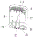
图14为一实施例中尘杯组件的结构示意图;Fig. 14 is a schematic structural view of a dust cup assembly in an embodiment;

图15为一实施例中尘杯组件漏出排灰口的结构示意图;Fig. 15 is a structural schematic diagram of the dust cup assembly leaking out of the ash discharge port in an embodiment;

图16为沿图14中A-A方向的一个角度下的截面图;Fig. 16 is a cross-sectional view at an angle along the A-A direction in Fig. 14;

图17为沿图14中A-A方向的另一角度的截面图;Fig. 17 is a sectional view of another angle along the A-A direction in Fig. 14;

图18为沿图14中A-A方向的又一角度的截面图;Fig. 18 is a sectional view of another angle along the A-A direction in Fig. 14;

图19为一实施例中尘杯组件漏出进气口的结构示意图;Fig. 19 is a structural schematic diagram of the dust cup assembly leaking out of the air inlet in an embodiment;

图20为沿图19中B-B方向的一个角度的截面图;Figure 20 is a cross-sectional view at an angle along the B-B direction in Figure 19;

图21为沿图19中B-B方向的另一角度的截面图;Figure 21 is a sectional view of another angle along the B-B direction in Figure 19;

图22为一实施例中尘杯组件取出底壁后的结构示意图;Fig. 22 is a schematic structural view of the dust cup assembly in an embodiment after the bottom wall is taken out;

图23为一实施例中盖体与开关结构配合的结构示意图;Fig. 23 is a structural schematic diagram of the cooperation between the cover body and the switch structure in an embodiment;

图24为开关结构位于锁止状态时的结构示意图;Fig. 24 is a structural schematic diagram when the switch structure is in a locked state;

图25为开关结构位于解锁状态时的结构示意图;Fig. 25 is a structural schematic diagram when the switch structure is in an unlocked state;

图26为一实施例中的手持吸尘器的结构示意图;Fig. 26 is a schematic structural view of a handheld vacuum cleaner in an embodiment;

图27为一实施例中手持吸尘器的盖体处于打开状态的结构示意图;Fig. 27 is a schematic structural view of the cover of the handheld vacuum cleaner in an open state in an embodiment;

图28为一实施例中基站的结构示意图;Fig. 28 is a schematic structural diagram of a base station in an embodiment;

图29为图28中P区域的结构放大图;Figure 29 is an enlarged view of the structure of the P region in Figure 28;

图30为一实施例中基站沿竖直方向的截面图;Fig. 30 is a cross-sectional view of the base station along the vertical direction in an embodiment;

图31为图30中Q区域的结构放大图;Figure 31 is an enlarged view of the structure of the Q region in Figure 30;

图32为一实施例中基站的局部示意图;Fig. 32 is a partial schematic diagram of a base station in an embodiment;

图33为一实施例中尘袋安装架位于第一位置时的结构示意图;Fig. 33 is a structural schematic diagram of an embodiment when the dust bag installation frame is in the first position;

图34为一实施例中尘袋安装架位于第二位置时的结构示意图;Fig. 34 is a structural schematic diagram of an embodiment when the dust bag installation frame is in the second position;

图35为图30中S区域的结构放大图;Figure 35 is an enlarged view of the structure of the S area in Figure 30;

图36为一实施例中基站去除部分零件后的结构示意图;Fig. 36 is a schematic structural diagram of a base station after some parts are removed in an embodiment;

图37为一实施例中箱体的结构示意图;Fig. 37 is a schematic structural view of a box in an embodiment;

图38为一实施例中箱体的另一角度下的结构示意图;Fig. 38 is a structural schematic view of the box body at another angle in one embodiment;

图39为图30中R区域的结构放大图;Figure 39 is an enlarged view of the structure of the R region in Figure 30;

图40为一实施例中拆除部分外罩的结构示意图;Fig. 40 is a structural schematic diagram of removing part of the outer cover in an embodiment;

图41为图40中U区域的结构放大图;Figure 41 is an enlarged view of the structure of the U region in Figure 40;

图42为一实施例中基站的底座的分解示意图。Fig. 42 is an exploded schematic view of the base of the base station in an embodiment.

实施方式Implementation

下面将结合本发明实施例中的附图,对本发明实施例中的技术方案进行清楚、完整地描述,显然,所描述的实施例仅仅是本发明的一部分实施例,而不是全部的实施例。基于本发明中的实施例,本领域普通技术人员在没有作出创造性劳动前提下所获得的所有其他实施例,都属于本发明保护的范围。The following will clearly and completely describe the technical solutions in the embodiments of the present invention with reference to the accompanying drawings in the embodiments of the present invention. Obviously, the described embodiments are only part of the embodiments of the present invention, not all of them. Based on the embodiments of the present invention, all other embodiments obtained by persons of ordinary skill in the art without creative efforts fall within the protection scope of the present invention.

需要说明,若本发明实施例中有涉及方向性指示,则该方向性指示仅用于解释在某一特定姿态下各部件之间的相对位置关系、运动情况等,如果该特定姿态发生改变时,则该方向性指示也相应地随之改变。It should be noted that if there are directional indications involved in the embodiment of the present invention, the directional indications are only used to explain the relative positional relationship, movement conditions, etc. between the components in a specific posture. If the specific posture changes , then the directional indication changes accordingly.

另外,若本发明实施例中有涉及“第一”、“第二”等的描述,则该“第一”、“第二”等的描述仅用于描述目的,而不能理解为指示或暗示其相对重要性或者隐含指明所指示的技术特征的数量。由此,限定有“第一”、“第二”的特征可以明示或者隐含地包括至少一个该特征。另外,全文中出现的“和/或”的含义,包括三个并列的方案,以“A和/或B”为例,包括A方案、或B方案、或A和B同时满足的方案。另外,各个实施例之间的技术方案可以相互结合,但是必须是以本领域普通技术人员能够实现为基础,当技术方案的结合出现相互矛盾或无法实现时应当认为这种技术方案的结合不存在,也不在本发明要求的保护范围之内。In addition, if there are descriptions involving "first", "second" and so on in the embodiments of the present invention, the descriptions of "first", "second" and so on are only for descriptive purposes, and should not be interpreted as indicating or implying Its relative importance or implicitly indicates the number of technical features indicated. Thus, the features defined as "first" and "second" may explicitly or implicitly include at least one of these features. In addition, the meaning of "and/or" appearing in the whole text includes three parallel schemes, taking "A and/or B" as an example, including scheme A, scheme B, or schemes that both A and B satisfy. In addition, the technical solutions of the various embodiments can be combined with each other, but it must be based on the realization of those skilled in the art. When the combination of technical solutions is contradictory or cannot be realized, it should be considered that the combination of technical solutions does not exist , nor within the scope of protection required by the present invention.

在本申请的描述中,需要说明的是,除非另有明确的规定和限定,术语“安装”、“相连”、“连接”应做广义理解,例如,可以是固定连接,也可以是可拆卸连接,或一体地连接;可以是机械连接,也可以是电连接;可以是直接相连,也可以通过中间媒介间接相连,可以是两个元件内部的连通。对于本领域的普通技术人员而言,可以通过具体情况理解上述术语在本申请中的具体含义。In the description of this application, it should be noted that unless otherwise specified and limited, the terms "installation", "connection", and "connection" should be understood in a broad sense, for example, it can be a fixed connection or a detachable connection. Connected, or integrally connected; it may be mechanically connected or electrically connected; it may be directly connected or indirectly connected through an intermediary, and it may be the internal communication of two components. Those of ordinary skill in the art can understand the specific meanings of the above terms in this application based on specific situations.

参考图1,图1公开了一种清洁系统100,其包括手持式吸尘器和基站20。手持式吸尘器用于清理待清洁表面。基站20用于对接手持吸尘器101,基站20内设置有抽吸电机,抽吸电机用于产生吸力以将集尘室中的脏污通过排灰口转移到基站20的集尘腔内。当手持吸尘器101被放置到基站20上后,用户可通过按钮控制基站20内的抽吸电机启动,此时,手持吸尘器101里尘杯组件内的脏污会被抽吸电机产生的气流抽吸到基站20的集尘腔内。集尘腔内可以设置一次性尘袋或者设置集尘装置。Referring to FIG. 1 , FIG. 1 discloses a cleaning system 100 including a handheld vacuum cleaner and a base station 20 . Hand-held vacuum cleaners are used to clean the surface to be cleaned. The base station 20 is used for docking with the handheld vacuum cleaner 101. The base station 20 is provided with a suction motor, which is used to generate suction to transfer the dirt in the dust collection chamber to the dust collection cavity of the base station 20 through the dust discharge port. When the handheld vacuum cleaner 101 is placed on the base station 20, the user can control the suction motor in the base station 20 to start by pressing a button. At this time, the dirt in the dust cup assembly in the handheld vacuum cleaner 101 will be sucked by the airflow generated by the suction motor. into the dust collection chamber of the base station 20. A disposable dust bag or a dust collecting device may be arranged in the dust collecting cavity.

参考图2-3,图中箭头X方向为手持吸尘器的长度方向,Y方向为宽度方向,Z方向为高度方向。手持吸尘器101包括主机10、清洁头30和连接主机10和清洁头30的延伸管40。主机10包括机体2、尘杯组件1、风机组件3、电池包4和过滤件33。尘杯组件1、风机组件3、电池包4和过滤件33等均可以可拆卸的安装于机体2上。电池包4为风机组件3提供动力,风机组件3产生抽吸气流,抽吸气流将待清洁表面的脏污沿抽吸管道21吸入尘杯组件1内。电池包4设置于手柄22的下端,用于为风机组件3中的电机提供能量。Referring to Fig. 2-3, the arrow X direction in the figure is the length direction of the handheld vacuum cleaner, the Y direction is the width direction, and the Z direction is the height direction. The handheld vacuum cleaner 101 includes a main body 10 , a cleaning head 30 and an extension pipe 40 connecting the main body 10 and the cleaning head 30 . The host 10 includes a body 2 , a dust cup assembly 1 , a fan assembly 3 , a battery pack 4 and a filter 33 . The dust cup assembly 1 , the fan assembly 3 , the battery pack 4 and the filter element 33 can all be detachably installed on the body 2 . The battery pack 4 provides power for the fan assembly 3, and the fan assembly 3 generates a suction airflow, which sucks the dirt on the surface to be cleaned into the dust cup assembly 1 along the suction duct 21. The battery pack 4 is arranged at the lower end of the handle 22 to provide energy for the motor in the blower assembly 3 .

机体2body 2

参考图2-7,机体2包括用于握持的手柄22,机体2限定有抽吸管道21。机体2在水平放置时吸气管道设置于尘杯组件1的下方。具体地,机体2包括手柄22和与手柄22成一定角度的支撑部26,支撑部26用于支撑尘杯组件1和电机组件,支撑部26限定有抽吸管道21。机体2上设置有用于容纳风机组件3的外罩。外罩上可设置有显示屏,优选地,显示屏设置在外罩的后方,这样,用户在使用时可直观的观察到手持吸尘器101的使用状态。显示屏的形状可以与外罩的后壁的形状相匹配,成椭圆形,其中包括两个并排的区域,一个区域可显示电量,另一个区域可显示吸力、脏污程度等参数。沿抽吸管道21延伸方向机体2包括前端23和后端24,机体2的前端23设置有充电端子25。沿手持吸尘器101的高度方向充电端子25设置于尘杯组件1的下方。手柄22上还设置有扳机27,扳机27用于控制手持吸尘器101的启停,扳机27的外表面基本与手柄22的外表面平齐,扳机27在受力后像内移动,触发微动开关,以开启或关闭手持吸尘器101,扳机27的外表面与手柄22的外表面基本平齐,以防止用户误触。Referring to FIGS. 2-7 , the body 2 includes a handle 22 for holding, and the body 2 defines a suction duct 21 . When the body 2 is placed horizontally, the suction duct is arranged under the dust cup assembly 1 . Specifically, the body 2 includes a handle 22 and a support portion 26 at a certain angle to the handle 22 , the support portion 26 is used to support the dust cup assembly 1 and the motor assembly, and the support portion 26 defines a suction duct 21 . The machine body 2 is provided with an outer cover for accommodating the fan assembly 3 . A display screen can be arranged on the outer cover, preferably, the display screen is arranged behind the outer cover, so that the user can intuitively observe the use status of the handheld vacuum cleaner 101 during use. The shape of the display, which can match the shape of the rear wall of the housing, is oval and includes two side-by-side areas, one for battery level and the other for suction, dirtiness, etc. parameters. The body 2 includes a front end 23 and a rear end 24 along the extending direction of the suction pipe 21 , and the front end 23 of the body 2 is provided with a charging terminal 25 . The charging terminal 25 is disposed below the dust cup assembly 1 along the height direction of the handheld vacuum cleaner 101 . The handle 22 is also provided with a trigger 27, the trigger 27 is used to control the start and stop of the hand-held vacuum cleaner 101, the outer surface of the trigger 27 is basically flush with the outer surface of the handle 22, and the trigger 27 moves inside after being stressed to trigger the micro switch , to turn on or off the handheld vacuum cleaner 101, the outer surface of the trigger 27 is substantially flush with the outer surface of the handle 22, so as to prevent the user from accidentally touching.

风机组件3Fan assembly 3

参考图6-11,图中箭头X方向为手持吸尘器(风机组件)的长度方向,Y方向为宽度方向,Z方向为高度方向。风机组件3设置于机体2,用于产生抽吸气流。风机组件3设置于手柄22的上方。风机组件3与电池包4分别设置于手柄22的两端。风机组件3包括风机31、过滤件33和风机罩32。沿手持吸尘器101的宽度方向风机31和过滤件33分别位于手柄轴线O两侧,风机31用于产生抽吸气流。过滤件33用于对风机31的排出气流进行过滤。风机罩32限定有容纳至少部分风机31的风机容纳腔321和容纳至少部分过滤件33的过滤件容纳腔322。风机罩32还限定有连通风机容纳腔321和过滤件容纳腔322的出风通道323。沿风机罩32的宽度方向出风通道323位于风机容纳腔321的一侧,出风通道323包括进口和出口,出风通道323的进口和出口之间设置有沿风机罩32的宽度方向弯折延伸的风道。继续参考图9和10,图中的箭头方向为风机的出风流动方向。出风通道323包括依次连通的向上延伸的垂直段、沿宽度方向延伸的水平段和斜向下延伸的倾斜段。当然,出风通道323除了图中所示的上下弯折延伸方式外,还可以水平弯折延伸,即出风通道323可以先向前延伸,然后再向后延伸,整体上弯折延伸至出口。当然,弯折延伸还可以以任意角度或者路径在风机罩32内弯折延伸。Referring to Figure 6-11, the X direction of the arrow in the figure is the length direction of the handheld vacuum cleaner (fan assembly), the Y direction is the width direction, and the Z direction is the height direction. The fan assembly 3 is arranged on the machine body 2 for generating suction airflow. The fan assembly 3 is disposed above the handle 22 . The fan assembly 3 and the battery pack 4 are respectively disposed at two ends of the handle 22 . The fan assembly 3 includes a fan 31 , a filter 33 and a fan cover 32 . Along the width direction of the handheld vacuum cleaner 101 , the blower 31 and the filter 33 are respectively located on both sides of the handle axis O, and the blower 31 is used to generate suction airflow. The filter element 33 is used to filter the exhaust airflow of the fan 31 . The fan cover 32 defines a fan accommodating cavity 321 for accommodating at least part of the fan 31 and a filter accommodating cavity 322 for accommodating at least a part of the filter element 33 . The fan cover 32 also defines an air outlet channel 323 communicating with the fan accommodating chamber 321 and the filter accommodating chamber 322 . The air outlet channel 323 is located on one side of the fan housing cavity 321 along the width direction of the fan cover 32 , the air outlet channel 323 includes an inlet and an outlet, and there is a bend along the width direction of the fan cover 32 between the inlet and the outlet of the air outlet channel 323 . Extended duct. Continuing to refer to FIGS. 9 and 10 , the direction of the arrow in the figure is the flow direction of the air blown by the fan. The air outlet channel 323 includes a vertical section extending upward, a horizontal section extending along the width direction, and an inclined section extending obliquely downward in sequence. Of course, in addition to the upward and downward bending extension shown in the figure, the air outlet channel 323 can also be bent and extended horizontally, that is, the air outlet channel 323 can first extend forward, and then extend backward, and extend to the outlet as a whole. . Of course, the bent extension can also be bent and extended in the fan cover 32 at any angle or path.

参考图8-11,出风通道323的出口设置有多个出风孔324。出风通道323的出口区域为弧形出口区域,弧形出口区域在风机罩32的宽度方向上沿远离风机容纳腔321的方向凸出。具体地,出风孔324基本布满整个弧形出口区域,弧形出口区域形成的凹腔朝向风机31所在位置。为了配合弧形出口区域,过滤件33呈扇环形,过滤件33包括进风面331和出风面332,进风面331的面积小于出风面332面积。进风面331朝向弧形出口区域,出风面332远离弧形出口区域,这样,过滤件33采用扇环形,在增加过滤面积的同时,可进一步降低噪音。过滤件33可以为过滤海帕,还可以是过滤海绵或由其他过滤材料制成。Referring to FIGS. 8-11 , the outlet of the air outlet channel 323 is provided with a plurality of air outlet holes 324 . The outlet area of the air outlet channel 323 is an arc-shaped outlet area, and the arc-shaped outlet area protrudes in a direction away from the fan housing cavity 321 in the width direction of the fan cover 32 . Specifically, the air outlet holes 324 basically cover the entire arc-shaped outlet area, and the concave cavity formed by the arc-shaped outlet area faces the location of the fan 31 . In order to cooperate with the arc-shaped outlet area, the filter element 33 is fan-shaped. The filter element 33 includes an air inlet surface 331 and an air outlet surface 332 . The area of the air inlet surface 331 is smaller than that of the air outlet surface 332 . The air inlet surface 331 faces the arc-shaped outlet area, and the air-outlet surface 332 is far away from the arc-shaped outlet area. In this way, the filter element 33 adopts a fan ring shape, which can further reduce noise while increasing the filtering area. The filter element 33 can be filter hypa, filter sponge or be made of other filter materials.

参考图7-9,过滤件33沿风机罩32的长度方向可拆装地安装于风机罩32限定的过滤件容纳腔322。风机罩32上限定有安装孔327,过滤件33可从安装孔327处安装于过滤件容纳腔322。在本实施例中,只有当尘杯组件1从机体2上取下时,过滤件33才可以从安装孔327取出。Referring to FIGS. 7-9 , the filter element 33 is detachably installed in the filter accommodation cavity 322 defined by the fan cover 32 along the length direction of the fan cover 32 . An installation hole 327 is defined on the fan cover 32 , and the filter element 33 can be installed in the filter element accommodating cavity 322 through the installation hole 327 . In this embodiment, only when the dust cup assembly 1 is removed from the body 2 , the filter element 33 can be removed from the installation hole 327 .

参考图7-11,风机罩32包括前壳体325和后壳体326,前壳体325和后壳体326共同限定风机容纳腔321,前壳体325和后壳体326共同限定过滤件容纳腔322,出风通道323由后壳体326单独限定。前壳体325限定有可拆装过滤件33的安装孔327。风机罩32设置有过线孔328,过线孔328连通出风通道323和风机罩32的外部空间。电机线可以通过过线孔328从风机容纳腔321中延伸至风机罩32的外侧。7-11, the fan cover 32 includes a front housing 325 and a rear housing 326, the front housing 325 and the rear housing 326 jointly define the fan housing cavity 321, and the front housing 325 and the rear housing 326 jointly define the filter housing. The cavity 322 and the air outlet channel 323 are separately defined by the rear housing 326 . The front housing 325 defines a mounting hole 327 through which the filter element 33 can be detached. The fan cover 32 is provided with a wire passing hole 328 , and the wire passing hole 328 communicates with the air outlet channel 323 and the outer space of the fan cover 32 . The motor wires can extend from the fan accommodation cavity 321 to the outside of the fan cover 32 through the wire passing holes 328 .

尘杯组件1Dust cup assembly 1

参考图12-14,同时参考图2-5,尘杯组件1设置于机体2上沿抽吸管道21延伸方向设置于沿风机组件3的前方。尘杯组件1包括旋风分离室12和集尘室13,旋风分离室12和集尘室13之间通过甩灰口14连通,沿手持吸尘器101的宽度方向旋风分离室12和集尘室13并排设置。Referring to Figures 12-14 and Figures 2-5 at the same time, the dust cup assembly 1 is arranged on the machine body 2 along the direction in which the suction pipe 21 extends and in front of the fan assembly 3 . The dust cup assembly 1 includes a cyclone separation chamber 12 and a dust collection chamber 13, and the cyclone separation chamber 12 and the dust collection chamber 13 are communicated through the dust removal port 14, and the cyclone separation chamber 12 and the dust collection chamber 13 are side by side along the width direction of the hand-held vacuum cleaner 101 set up.

参考图14-19,尘杯组件1包括壳体11,壳体11包括侧壁111和底壁112,其内限定有旋风分离室12和集尘室13,至少部分侧壁111和至少部分底壁112共同限定用于收集脏污的集尘室13。集尘室13设置于旋风分离室12外部且通过甩灰口14与旋风分离室12连通。具体地,壳体11呈椭圆形,沿其宽度方向分成两部分,一部分是旋风分离室12,旋风分离室12的内壁呈筒状,这样可以有效提高分离效率。集尘室13设置于旋风分离室12的一侧,壳体11包括周壁和底壁112,底壁112上设置有盖体132,盖体132用于打开/关闭集尘室13的排灰口131。沿尘杯组件1的长度方向壳体11包括相对的第一端113和第二端114,底壁112设置于第一端113,底壁112设置有排灰口131和用于打开/封闭排灰口131的盖体132,甩灰口14设置于靠近第二端114的位置。14-19, the dust cup assembly 1 includes a housing 11, the housing 11 includes a side wall 111 and a bottom wall 112, which defines a cyclone separation chamber 12 and a dust collection chamber 13, at least part of the side wall 111 and at least part of the bottom The walls 112 together define a dust chamber 13 for collecting dirt. The dust collection chamber 13 is arranged outside the cyclone separation chamber 12 and communicates with the cyclone separation chamber 12 through the ash rejection port 14 . Specifically, the housing 11 is elliptical and divided into two parts along its width direction, one part is a cyclone separation chamber 12, and the inner wall of the cyclone separation chamber 12 is cylindrical, which can effectively improve the separation efficiency. The dust collection chamber 13 is arranged on one side of the cyclone separation chamber 12, and the housing 11 includes a peripheral wall and a bottom wall 112. The bottom wall 112 is provided with a cover 132, and the cover 132 is used to open/close the dust discharge port of the dust collection chamber 13. 131. Along the length direction of the dust cup assembly 1, the housing 11 includes an opposite first end 113 and a second end 114, the bottom wall 112 is arranged on the first end 113, the bottom wall 112 is provided with an ash discharge port 131 and is used for opening/closing the discharge port. The cover body 132 of the ash port 131 and the ash ejection port 14 are arranged near the second end 114 .

参考图16-21,排灰口131的面积小于集尘室13的沿垂直于尘杯组件1长度方向的截面面积。侧壁111和排灰口131之间设置有引导结构18,用于将集尘室13内的脏污引导至排灰口131。沿从第二端114到第一端113的延伸方向,引导结构18所限定的脏污通道逐渐变小。引导结构18基本上呈喇叭状,朝向排灰口131的方向引导结构18的内径逐渐变小。采用排灰口131的面积比集尘室13的横截面积小,会导致在排空集尘室13的时候,部分脏污会卡到集尘室13靠近排灰口131的边缘。位于该边缘位置的脏污不容易清理,因此,在排灰口131和侧壁111之间设置引导结构18,以引导脏污避开排灰口131上方的边缘,以顺利从排灰口131排出。进一步地,盖体132的面积大于排灰口131的面积而小于集尘室13的横截面积。Referring to FIGS. 16-21 , the area of the dust discharge port 131 is smaller than the cross-sectional area of the dust collection chamber 13 along the direction perpendicular to the length of the dust cup assembly 1 . A guide structure 18 is provided between the side wall 111 and the ash discharge port 131 for guiding the dirt in the dust collecting chamber 13 to the ash discharge port 131 . Along the extending direction from the second end 114 to the first end 113, the dirt channel defined by the guide structure 18 becomes gradually smaller. The guide structure 18 is basically trumpet-shaped, and the inner diameter of the guide structure 18 gradually becomes smaller toward the direction of the ash discharge port 131 . The area of the dust discharge port 131 is smaller than the cross-sectional area of the dust collection chamber 13, which will cause some dirt to be stuck to the edge of the dust collection chamber 13 near the dust discharge port 131 when the dust collection chamber 13 is emptied. The dirt at this edge position is not easy to clean, therefore, a guide structure 18 is provided between the ash discharge port 131 and the side wall 111 to guide the dirt away from the edge above the ash discharge port 131, so as to smoothly pass through the ash discharge port 131 discharge. Further, the area of the cover body 132 is larger than the area of the ash outlet 131 and smaller than the cross-sectional area of the dust collection chamber 13 .

为了实现盖体132的开/闭,尘杯组件1上还设置有开关结构15。开关结构15设置于底壁112处。开关结构15用于解锁盖体132以使盖体132可相对于底壁112运动以打开集尘室13的排灰口131,至少部分开关结构15贯穿底壁112。参考图23-25,图中箭头为零件可移动方向。开关结构15包括触动件151和锁止件152,触动件151受力后可使锁止件152处于解锁状态。触动件151贯穿底壁112,外部结构可以从底壁112的下方触发触动件151,而不需要在侧壁111周围设置其他的结构。触动件151沿垂直于底壁112的方向运动以带动锁止件152沿平行于底壁112的方向运动。触动件151的外表面与底壁112的外表面基本在同一平面内,这样可以有效避免触动件151被误触。In order to realize the opening/closing of the cover body 132 , a switch structure 15 is also provided on the dust cup assembly 1 . The switch structure 15 is disposed at the bottom wall 112 . The switch structure 15 is used to unlock the cover body 132 so that the cover body 132 can move relative to the bottom wall 112 to open the ash outlet 131 of the dust collection chamber 13 , at least part of the switch structure 15 penetrates the bottom wall 112 . Referring to Figures 23-25, the arrows in the figure indicate the movable direction of the parts. The switch structure 15 includes an actuating member 151 and a locking member 152 , and the actuating member 151 can make the locking member 152 in an unlocked state after being stressed. The actuating member 151 runs through the bottom wall 112 , and the external structure can trigger the actuating member 151 from below the bottom wall 112 without setting other structures around the side wall 111 . The actuating member 151 moves along a direction perpendicular to the bottom wall 112 to drive the locking member 152 to move along a direction parallel to the bottom wall 112 . The outer surface of the actuating member 151 and the outer surface of the bottom wall 112 are substantially in the same plane, which can effectively prevent the actuating member 151 from being accidentally touched.

参考图19-21,旋风分离室12内侧壁111开设有进气口122,进气口122设置于壳体11的第一端113。旋风分离室12还包括引导壁121,引导壁121的作用是引导从进气口122进入的气流进行旋风分离室12内进行旋风分离。引导壁121和底壁112之间限定有安装腔16,至少部分开关结构15设置于安装腔16内。这样,可以有效的节省空间。参考图,沿尘杯组件1的长度方向,进气口122的高度大于引导结构18的高度。引导结构18的高度比较小,在起到引导作用的同时,有效增加集尘室13的有效容积。Referring to FIGS. 19-21 , the inner wall 111 of the cyclone separation chamber 12 is provided with an air inlet 122 , and the air inlet 122 is disposed at the first end 113 of the casing 11 . The cyclone separation chamber 12 further includes a guide wall 121 , the function of the guide wall 121 is to guide the airflow entering from the air inlet 122 to perform cyclone separation in the cyclone separation chamber 12 . An installation cavity 16 is defined between the guide wall 121 and the bottom wall 112 , and at least part of the switch structure 15 is disposed in the installation cavity 16 . In this way, space can be effectively saved. Referring to the figure, along the length direction of the dust cup assembly 1 , the height of the air inlet 122 is greater than that of the guide structure 18 . The height of the guide structure 18 is relatively small, which effectively increases the effective volume of the dust collecting chamber 13 while playing a guiding role.

参考图14-15,排灰口131设置于集尘室13对应的底壁112处。在其他实施例中,排灰口131还可以部分覆盖部分或全部覆盖旋风分离室12对应的底壁112。具体地,底壁112包括与旋风分离室12对应的第一区域115和与集尘室13对应的第二区域116,触动件151设置于第一区域115。盖体132的面积小于第一区域115的面积。盖体132面积设计的比较小,可以有效缩小基站20的接触面积,同时,缩小盖体132的面积(即排灰口131的面积),可以增加吸力,使尘杯组件1内的灰尘更容易被抽吸到集尘腔内。排灰口131的边缘位于侧壁111的边缘的内侧。Referring to FIGS. 14-15 , the ash outlet 131 is provided at the corresponding bottom wall 112 of the dust collection chamber 13 . In other embodiments, the ash outlet 131 may also partially cover partly or fully cover the corresponding bottom wall 112 of the cyclone separation chamber 12 . Specifically, the bottom wall 112 includes a first area 115 corresponding to the cyclone separation chamber 12 and a second area 116 corresponding to the dust collection chamber 13 , and the contact element 151 is disposed on the first area 115 . The area of the cover 132 is smaller than the area of the first region 115 . The area of the cover 132 is designed to be relatively small, which can effectively reduce the contact area of the base station 20. At the same time, reducing the area of the cover 132 (that is, the area of the ash discharge port 131) can increase the suction force and make it easier for the dust in the dust cup assembly 1 to is sucked into the dust collection chamber. The edge of the ash outlet 131 is located inside the edge of the side wall 111 .

参考图14-15,尘杯组件1还包括锁止结构17,用于解锁/锁止尘杯组件1,锁止结构17位于底壁112的第一区域115和第二区域116的交汇处。锁止结构17包括按钮171,按钮171凸出于底壁112。Referring to FIGS. 14-15 , the dust cup assembly 1 further includes a locking structure 17 for unlocking/locking the dust cup assembly 1 , and the locking structure 17 is located at the junction of the first area 115 and the second area 116 of the bottom wall 112 . The locking structure 17 includes a button 171 protruding from the bottom wall 112 .

盖体132包括打开状态和关闭状态,盖体132设置有保持结构133,保持结构133配置成使盖体132在不受外力的作用下始终保持在关闭状态。当手持吸尘器101放置到基站20后,盖体132处于可打开状态,但是其在保持结构133的作用下,盖体132继续密封排灰口131,如果排灰口131处有脏污,且脏污的重力较大,盖体132可能会被打开。当基站20中的抽吸电机启动后,会产生较大的吸力,此时,作用在盖体132的吸力克服保持结构133产生的力,使盖体132处于打开状态,此时,集尘室13内的脏污会被抽吸到集尘腔内。当抽吸电机停止后,盖体132在保持结构133的作用下回到关闭位置,处于关闭状态。保持结构133可以为一个扭簧,当然还可以为其他机械结构。The cover 132 includes an open state and a closed state, and the cover 132 is provided with a holding structure 133 configured to keep the cover 132 always in the closed state without external force. When the handheld vacuum cleaner 101 is placed on the base station 20, the cover body 132 is in an openable state, but under the action of the holding structure 133, the cover body 132 continues to seal the ash discharge port 131. If the ash discharge port 131 is dirty and dirty The gravity of dirt is bigger, and cover body 132 may be opened. After the suction motor in the base station 20 is started, a greater suction force will be generated. At this time, the suction force acting on the cover body 132 overcomes the force generated by the holding structure 133, so that the cover body 132 is in an open state. At this time, the dust collection chamber Dirt in 13 can be sucked in the dust collecting cavity. After the suction motor stops, the cover body 132 returns to the closed position under the action of the holding structure 133 and is in a closed state. The holding structure 133 can be a torsion spring, and of course it can also be other mechanical structures.

参考图16-21,尘杯组件1的第二端114设置过滤器支架51,过滤器支架51的相对两端可分别放置第一过滤器52和第二过滤器53,第一过滤器52设置于旋风分离室12内,第二过滤器53设置于旋风分离室12外。以垂直于分离轴线的平面为横截面,第二过滤器53的截面积大于旋风分离室12的截面积且小于尘杯组件1的截面积。第一过滤器52和第二过滤器53均为电机前过滤器。16-21, the second end 114 of the dust cup assembly 1 is provided with a filter holder 51, and the opposite ends of the filter holder 51 can respectively place a first filter 52 and a second filter 53, and the first filter 52 is provided In the cyclone separation chamber 12 , the second filter 53 is disposed outside the cyclone separation chamber 12 . Taking a plane perpendicular to the separation axis as the cross-section, the cross-sectional area of the second filter 53 is larger than that of the cyclone separation chamber 12 and smaller than that of the dust cup assembly 1 . Both the first filter 52 and the second filter 53 are pre-motor filters.

基站base station

参考图1,同时可参考图26和27,基站20用于对接至少部分表面清洁设备101,至少用来对接表面清洁设备的尘杯组件,手持吸尘器可以整体放置于基站上,还可以将尘杯组件单独拆下放置于基站上。参考图28,基站包括对接组件28、底座27和连接对接组件28和底座27的延伸杆26,对接组件28和底座27分别设置于延伸杆26的两端。Referring to Fig. 1 and Figs. 26 and 27 at the same time, the base station 20 is used to dock at least part of the surface cleaning equipment 101, at least for docking the dust cup assembly of the surface cleaning equipment, the handheld vacuum cleaner can be placed on the base station as a whole, and the dust cup can also be placed The components are removed separately and placed on the base station. Referring to FIG. 28 , the base station includes a docking assembly 28 , a base 27 and an extension rod 26 connecting the docking assembly 28 and the base 27 , and the docking assembly 28 and the base 27 are respectively arranged at two ends of the extension rod 26 .

参考图28、29和31,对接组件28包括箱体281和接收支架282,箱体281限定有集尘腔22,接收支架282用于接收至少部分表面清洁设备。箱体281用于支撑接收支架282。箱体281可以跟接收支架282一体成型,两个还可以分开设置。为了接收盖体,接收支架282还包括用于接收盖体的接收槽284和与接收槽284连通的通道285。具体地,接收支架282包括对接槽286,对接槽286用于对接至少部分表面清洁设备,尤其是表面清洁设备的尘杯,部分尘杯伸入到对接槽286内。因此,将集尘室的盖体做的比较小,至少比集尘室的横截面积小,可以有效降低对接槽286的占用空间。对接槽286由顶壁291和设置于顶壁291周围的周壁294限定而成。对接槽286可以由顶壁291向下凹陷而成,还可以是周壁294相对于顶壁291向上延伸而成。参考图,顶壁291包括第三区域292和第四区域293,接收槽284设置于第三区域292内,开盖机构288设置于第四区域293。盖体的面积小于第三区域292的面积。当手持吸尘器对接到基站后,盖体可向外打开,即需要基站必须容纳下盖272体,如果盖体非常大的话,那么与盖体对应的对接槽286将会变得很大,此时,至少部分基站会变得很大,而对接槽286仅仅为对接作用,并没有收纳脏污的作用,因此,过大的对接槽286会浪费空间。Referring to FIGS. 28 , 29 and 31 , the docking assembly 28 includes a box body 281 defining a dust collection cavity 22 and a receiving bracket 282 for receiving at least part of a surface cleaning device. The box body 281 is used to support the receiving bracket 282 . The box body 281 can be integrally formed with the receiving bracket 282, and the two can also be set separately. In order to receive the cover, the receiving bracket 282 further includes a receiving slot 284 for receiving the cover and a channel 285 communicating with the receiving slot 284 . Specifically, the receiving bracket 282 includes a docking slot 286 for docking at least part of the surface cleaning equipment, especially the dust cup of the surface cleaning equipment, and part of the dust cup extends into the docking slot 286 . Therefore, making the cover of the dust collection chamber smaller, at least smaller than the cross-sectional area of the dust collection chamber, can effectively reduce the occupied space of the docking groove 286 . The docking slot 286 is defined by a top wall 291 and a peripheral wall 294 disposed around the top wall 291 . The docking groove 286 may be formed by a downward depression of the top wall 291 , or may be formed by an upward extension of the peripheral wall 294 relative to the top wall 291 . Referring to the figure, the top wall 291 includes a third area 292 and a fourth area 293 , the receiving groove 284 is disposed in the third area 292 , and the cover opening mechanism 288 is disposed in the fourth area 293 . The area of the cover is smaller than the area of the third region 292 . When the handheld vacuum cleaner is docked to the base station, the cover can be opened outwards, that is, the base station must accommodate the lower cover 272. If the cover is very large, the docking groove 286 corresponding to the cover will become very large. At this time , at least some of the base stations will become very large, and the docking slot 286 is only for docking, and has no function of accommodating dirt. Therefore, an overly large docking slot 286 will waste space.

参考图31,接收槽284整体呈喇叭状,沿远离对接槽286的方向截面积逐渐变小,直至连接到通道285。通道285可深入集尘腔22的尘袋29内。接收支架282限定有漏斗形的接收槽284和连通集尘腔22和接收槽284的通道285,用于将尘杯组件中的脏污引导至集尘腔22。Referring to FIG. 31 , the receiving groove 284 is trumpet-shaped as a whole, and its cross-sectional area gradually decreases along the direction away from the docking groove 286 until it is connected to the channel 285 . The channel 285 can go deep into the dust bag 29 of the dust collecting cavity 22 . The receiving bracket 282 defines a funnel-shaped receiving groove 284 and a channel 285 communicating with the dust collecting chamber 22 and the receiving groove 284 for guiding the dirt in the dust cup assembly to the dust collecting chamber 22 .

由于手持吸尘器还包括延伸管和清洁头,为了方便整个手持吸尘器对接到基站上,参考图29,周壁294构造有缺口295,用来容纳部分手持吸尘器的主机和/或延伸管,基站还可以为手持吸尘器充电,因此,基站上还应设置有充电触点296,为了方便充电,缺口295处设置有充电触点296。充电触点296一般设置在顶壁291上,这样,手持吸尘器放置到基站后即可与手持吸尘器的充电端子25(参考图26或27)对接。两者的对接完全靠手持吸尘器的重力维持,而不需要类似于其他弹性结构的外力进行维持,有效降低成本,还能增加设备的可靠性。充电触点296的数量为两个,分别设置于缺口295的两侧。Since the handheld vacuum cleaner also includes an extension pipe and a cleaning head, in order to facilitate the docking of the entire handheld vacuum cleaner on the base station, referring to FIG. The handheld vacuum cleaner is charged. Therefore, the base station should also be provided with a charging contact 296. In order to facilitate charging, the gap 295 is provided with a charging contact 296. The charging contacts 296 are generally arranged on the top wall 291 , so that the handheld vacuum cleaner can be docked with the charging terminal 25 (refer to FIG. 26 or 27 ) after being placed on the base station. The docking of the two is completely maintained by the gravity of the handheld vacuum cleaner, without the need for external force similar to other elastic structures, which effectively reduces costs and increases the reliability of the equipment. There are two charging contacts 296 , which are respectively disposed on two sides of the notch 295 .

参考图30-34,集尘腔22内设置有用于安装尘袋29的尘袋安装架23,尘袋安装架23可枢转的设置于集尘腔22内。尘袋安装架23一般为可绕一端枢转的框架结构,其限定有安装槽,尘袋29可沿安装槽的延伸方向拆/装。尘袋安装架23包括第一位置和第二位置,在第一位置时,尘袋29接收至少部分通道285;此时,尘袋29不能被取下。如图中所示实施例,在尘袋安装架23位于第一位置时,尘袋安装架23与通道285基本垂直。当然,在其他实施例中,尘袋29的位置可以根据基站的形状布置。在第二位置时,尘袋29离开通道285,以使尘袋29可从尘袋安装架23取出。这里所描述的离开,是相对于尘袋安装架23位于第一位置所说,并不代表尘袋29离通道285很远,只需尘袋29能从支架上取出即可。图34中的箭头方向即为取出方向。Referring to FIGS. 30-34 , a dust bag installation frame 23 for installing a dust bag 29 is provided in the dust collection chamber 22 , and the dust bag installation frame 23 is pivotably disposed in the dust collection chamber 22 . The dust bag mounting frame 23 is generally a frame structure that can pivot around one end, and defines a mounting slot, and the dust bag 29 can be disassembled/installed along the extending direction of the mounting slot. The dust bag mounting frame 23 includes a first position and a second position. In the first position, the dust bag 29 receives at least part of the channel 285; at this time, the dust bag 29 cannot be removed. In the embodiment shown in the figure, when the dust bag mounting frame 23 is in the first position, the dust bag mounting frame 23 is substantially perpendicular to the channel 285 . Of course, in other embodiments, the position of the dust bag 29 can be arranged according to the shape of the base station. In the second position, the dust bag 29 leaves the channel 285 so that the dust bag 29 can be taken out from the dust bag mounting frame 23 . The departure described here is relative to the fact that the dust bag installation frame 23 is located at the first position, and it does not mean that the dust bag 29 is far away from the channel 285, only that the dust bag 29 can be taken out from the bracket. The direction of the arrow in Figure 34 is the take-out direction.

参考图32-34,为了防止尘袋29漏装,基站设置有尘袋检测装置,尘袋29监测装置构造成用于检测尘袋安装架23上是否安装有尘袋29。进一步地,尘袋29监测装置配置成仅在尘袋安装架23位于第一位置时可检测尘袋安装架23上是否安装有尘袋29。这样设置的好处是即使尘袋安装架23处于第一位置,但是尘袋29安装支架上没有安装尘袋29,基站可以提示用户没有安装尘袋29或者基站内的抽吸电机21无法工作,避免在没有尘袋29的情况下,尘杯组件内的脏污被转移到集尘腔22内。32-34, in order to prevent the dust bag 29 from being missing, the base station is provided with a dust bag detection device, and the dust bag 29 monitoring device is configured to detect whether the dust bag 29 is installed on the dust bag installation frame 23. Further, the dust bag 29 monitoring device is configured to detect whether the dust bag 29 is installed on the dust bag mounting frame 23 only when the dust bag mounting frame 23 is in the first position. The advantage of setting like this is that even if the dust bag mounting bracket 23 is in the first position, but the dust bag 29 is not installed on the dust bag 29 mounting bracket, the base station can remind the user that the dust bag 29 is not installed or the suction motor 21 in the base station cannot work, so as to avoid In the absence of the dust bag 29 , the dirt in the dust cup assembly is transferred to the dust collection cavity 22 .

继续参考图32-34,尘袋检测装置包括防漏装开关,尘袋安装架23位于第一位置时,防漏装开关处于导通状态,基站内的抽吸电机21可操作,尘袋安装架23位于第二位置时,防漏装开关位于断开状态,抽吸电机21不可操作。防漏装开关可以包括信号发生器和控制器,信号发生器可以为例如红外接收/发射器或其他可检测的器件,这些元器件与线路板223连通,通过发送第一信号给控制器,控制器通过第一信号来识别集尘腔22内是否有尘袋29。参考图,防漏装开关还可以是机械式开关。防漏装开关包括第一微动开关252和用于触发微动开关的可移动的接触件251,尘袋29在尘袋安装架23从第一位置到第二位置移动的过程中以使接触件251发生位移。为了确保检测结果的准确性,第一微动开关252位于尘袋29的正上方。当然,第一微动开关252还可以设置于尘袋29的其他位置。Continuing to refer to Figures 32-34, the dust bag detection device includes a leak-proof switch. When the dust bag installation frame 23 is in the first position, the leak-proof switch is in the conduction state, the suction motor 21 in the base station is operable, and the dust bag is installed. When the frame 23 is in the second position, the leak-proof switch is in the off state, and the suction motor 21 cannot be operated. The leak-proof switch can include a signal generator and a controller, and the signal generator can be, for example, an infrared receiver/transmitter or other detectable devices, and these components are communicated with the circuit board 223, and are controlled by sending the first signal to the controller. The device identifies whether there is a dust bag 29 in the dust collecting cavity 22 through the first signal. Referring to the figure, the leak-proof switch can also be a mechanical switch. The leak-proof switch includes a first micro switch 252 and a movable contact 251 for triggering the micro switch, and the dust bag 29 makes the contact when the dust bag installation frame 23 moves from the first position to the second position. Member 251 is displaced. In order to ensure the accuracy of the detection result, the first micro switch 252 is located directly above the dust bag 29 . Of course, the first micro switch 252 can also be arranged at other positions of the dust bag 29 .

参考图37-39,箱体281的下方设置有连通口,用于连通集尘腔22和抽吸电机21的抽风口211,连通口包括向集尘腔22内凸起的空腔276和位于空腔276两侧的第一连通口274和第二连通口275。第一连通口274包括至少一个通孔277,第二连通口275包括至少一个通孔277,第一连通口274和第二连通口275分别位于向内凹陷的空腔276的两侧,可以使气流分布更均匀。通孔277为长条状通孔277,部分通孔277位于空腔276的侧壁,部分位于箱体281的底壁,进一步平衡气流,使集尘腔22内气流更加平稳,避免出现涡流等现象,提高抽吸效率。Referring to Figures 37-39, a communication port is provided below the box body 281 for communicating with the dust collection chamber 22 and the suction port 211 of the suction motor 21. The communication port includes a cavity 276 protruding into the dust collection chamber 22 and located at The first communication port 274 and the second communication port 275 on both sides of the cavity 276 . The first communication port 274 includes at least one through hole 277, and the second communication port 275 includes at least one through hole 277. The first communication port 274 and the second communication port 275 are respectively located on both sides of the inwardly recessed cavity 276, so that The airflow is more evenly distributed. The through hole 277 is a strip-shaped through hole 277, part of the through hole 277 is located on the side wall of the cavity 276, and part of it is located on the bottom wall of the box body 281, so as to further balance the air flow, make the air flow in the dust collection chamber 22 more stable, and avoid eddy currents, etc. Phenomenon, improve suction efficiency.

参考图28、29、40和41,为了实现将手持吸尘器放置到基站后,盖体能自动解锁,基站的对接槽286内还设置有开盖机构288,述接收支架282还包括贯穿顶壁291的开盖机构288。开盖机构288可以为一杆状结构,其可以贯穿顶壁291,还可以不贯穿顶壁291,直接为顶壁291上的一个凸起。当手持吸尘器放置到基站后,开盖机构288触发盖体的开关结构,盖体处于解锁状态。清洁系统还包括控制器,配置成控制抽吸电机21的启/停。控制器可以设置在基站上,还可以设置在表面清洁设备上。基站上设置有开盖机构288,开盖机构288配置成在表面清洁设备对接至基站后使盖体处于解锁状态且同时发出对接信号,控制器在接收到对接信号后可控制抽吸电机21启/停。这里所说的盖体处于解锁状态是指盖体可以在不收外力的作用下,密封尘杯组件的排灰口,在受到外力作用时可以打开排灰口,还可以是在不受外力的作用下直接打开排灰口,例如在本身重力的作用下就可打开排灰口。同时,开盖机构288还能发出对接信号,例如:开盖机构288中包括传感器等,可以检测到表面清洁设备已经对接到基站,传感器可以为红外传感器、霍尔传感器等,此处不对其类型进行限制,只是列举。将开盖机构288设计成既能解锁盖体,又能发出信号,可以有效避免盖体没有打开时抽吸电机21启动,从而避免抽吸电机21损坏,同时提高用户体验。参考图40和41,开盖机构288还可以是如下结构:开盖机构288包括位移件231和第二微动开关232,位移件231具有初始位置和开盖位置,在表面清洁设备对接至基站后,位移件231从初始位置移动至开盖位置,位移件231在开盖位置时触发第二微动开关232。Referring to Figures 28, 29, 40 and 41, in order to realize that the cover can be automatically unlocked after the handheld vacuum cleaner is placed on the base station, a cover opening mechanism 288 is also provided in the docking groove 286 of the base station, and the receiving bracket 282 also includes a penetrating top wall 291 Uncover mechanism 288. The opening mechanism 288 can be a rod-shaped structure, which can pass through the top wall 291 , and can also not pass through the top wall 291 , and can be directly a protrusion on the top wall 291 . When the handheld vacuum cleaner is placed on the base station, the cover opening mechanism 288 triggers the switch structure of the cover, and the cover is in an unlocked state. The cleaning system also includes a controller configured to control start/stop of the suction motor 21 . The controller can be located on the base station, and can also be located on the surface cleaning equipment. The base station is provided with an opening mechanism 288, and the opening mechanism 288 is configured to make the cover body in an unlocked state after the surface cleaning equipment is docked to the base station and at the same time send a docking signal, and the controller can control the suction motor 21 to start after receiving the docking signal. /stop. The cover body in the unlocked state mentioned here means that the cover body can seal the ash discharge port of the dust cup assembly without external force, and can open the ash discharge port when it is subjected to external force, or it can be without external force. The ash discharge port can be opened directly under the action, for example, the ash discharge port can be opened under the action of its own gravity. At the same time, the opening mechanism 288 can also send a docking signal. For example, the opening mechanism 288 includes sensors, etc., which can detect that the surface cleaning device has been docked to the base station. The sensors can be infrared sensors, Hall sensors, etc., and the types are not mentioned here. To limit, just to enumerate. The cover opening mechanism 288 is designed to not only unlock the cover, but also send a signal, which can effectively prevent the suction motor 21 from starting when the cover is not opened, thereby avoiding damage to the suction motor 21 and improving user experience at the same time. Referring to Figures 40 and 41, the cover opening mechanism 288 can also have the following structure: the cover opening mechanism 288 includes a displacement member 231 and a second micro switch 232, the displacement member 231 has an initial position and a cover opening position, and when the surface cleaning device is docked to the base station Afterwards, the displacement member 231 moves from the initial position to the cover opening position, and the displacement member 231 triggers the second micro switch 232 at the cover opening position.

参考图40和41,部分位移件231伸入到对接槽286内。也即是,位移件231贯穿对接槽286的顶壁291。当尘杯放入到对接槽286内以后,尘杯会接触到位移件231,此时,位移件231与尘杯上的触动件接触,使盖体处于解锁状态,同时,位移件231产生位移后,同时触发第二微动开关232,第二微动开关232发出对接信号。在接收到对接信号后,控制器控制抽吸电机21工作。Referring to FIGS. 40 and 41 , part of the displacement member 231 extends into the docking groove 286 . That is, the displacement member 231 penetrates through the top wall 291 of the docking slot 286 . When the dust cup is put into the docking groove 286, the dust cup will touch the displacement member 231. At this time, the displacement member 231 contacts with the touch member on the dust cup, so that the cover is in an unlocked state, and at the same time, the displacement member 231 generates a displacement. After that, the second micro switch 232 is triggered at the same time, and the second micro switch 232 sends out a docking signal. After receiving the docking signal, the controller controls the suction motor 21 to work.

进一步地,为了确保基站内尘袋29安装到位后才能启动抽吸电机21。基站内的尘袋检测装置配置成在尘袋29安装到位后发出第一信号,控制器在接收到第一信号和对接信号后方可控制抽吸电机21启/停。参考图,尘袋检测装置包括第一微动开关252和接触件251,当尘袋29安装号以后,第一微动开关252发出第一信号,同时第二微动开关232在尘杯放置好后发出对接信号,控制器在接收到第一信号和对接信号后可控制抽吸电机21启停。Further, in order to ensure that the dust bag 29 in the base station is installed in place, the suction motor 21 can only be started. The dust bag detection device in the base station is configured to send a first signal after the dust bag 29 is installed in place, and the controller can control the start/stop of the suction motor 21 only after receiving the first signal and the docking signal. Referring to the figure, the dust bag detection device includes a first micro switch 252 and a contact piece 251. After the dust bag 29 is installed, the first micro switch 252 sends a first signal, and at the same time the second micro switch 232 is placed on the dust cup. After the docking signal is sent, the controller can control the suction motor 21 to start and stop after receiving the first signal and the docking signal.

参考图29,清洁系统还包括控制按钮287,抽吸电机21包括可操作状态和不可操作状态,在处于抽吸电机21处于可操作状态时,可通过控制按钮287控制抽吸电机21的启/停。抽吸电机21的不可操作状态为不能人为的开启关闭。抽吸电机21的可操作状态是用户可控制抽吸电机21启停。控制按钮287设置于基站。控制按钮287还可以设置于表面清洁设备上,这样,当表面清洁设备没有对接到基站时,基站的抽吸电机21不能通过控制按钮287控制。为了实现手动控制,接收支架282上设置有控制按钮287,用于控制基站内的抽吸电机21的启停,用户可以手动控制基站里的抽吸电机21是否工作。Referring to Fig. 29, the cleaning system also includes a control button 287. The suction motor 21 includes an operable state and an inoperable state. When the suction motor 21 is in an operable state, the start/stop of the suction motor 21 can be controlled by the control button 287. stop. The inoperable state of the suction motor 21 is that it cannot be turned on or off artificially. The operable state of the suction motor 21 is that the user can control the suction motor 21 to start and stop. The control button 287 is disposed on the base station. The control button 287 can also be set on the surface cleaning device, so that when the surface cleaning device is not docked to the base station, the suction motor 21 of the base station cannot be controlled by the control button 287 . In order to realize manual control, the receiving bracket 282 is provided with a control button 287 for controlling the start and stop of the suction motor 21 in the base station, and the user can manually control whether the suction motor 21 in the base station is working.

参考图30和35,底座27用于支撑对接组件28,底座27限定有安装空间,安装空间内设置有用于产生抽吸气流的抽吸电机21。延伸杆26用于连接对接组件28和底座27,延伸杆26限定有气流管路261,气流管路261用于流体连通集尘腔22和抽吸电机21的抽风口211。通过延伸杆26将集尘腔22和抽吸电机21流体连通,一方面,由于抽吸电机21的重量较重,可以将基站的整体重心下移,同时采用延伸杆将抽吸电机21和集尘腔22流体连通,有效避免吸力的损失。另一方面,通过延伸杆26可以将集尘腔22设置在基站较高的位置,避免手持吸尘器的尘杯和集尘腔22之间存在较长的通道285,比较难清理。同时,采用延伸杆26,可以降低基站的成本。Referring to Figures 30 and 35, the base 27 is used to support the docking assembly 28, the base 27 defines an installation space, and a suction motor 21 for generating suction airflow is arranged in the installation space. The extension rod 26 is used for connecting the docking assembly 28 and the base 27 , and the extension rod 26 defines an airflow pipeline 261 , and the airflow pipeline 261 is used for fluidly connecting the dust collection chamber 22 and the air outlet 211 of the suction motor 21 . The dust collection chamber 22 and the suction motor 21 are in fluid communication through the extension rod 26. On the one hand, due to the heavy weight of the suction motor 21, the overall center of gravity of the base station can be moved down. The dust chamber 22 is in fluid communication, effectively avoiding loss of suction. On the other hand, the dust collection chamber 22 can be set at a higher position of the base station through the extension rod 26, so as to avoid the long channel 285 between the dust cup of the handheld vacuum cleaner and the dust collection chamber 22, which is difficult to clean. At the same time, the cost of the base station can be reduced by using the extension rod 26 .

参考图35,延伸杆26可以为中空的金属管,沿其轴向方向,延伸杆26包括相对设置的第一端和第二端,第一端可拆卸的安装于对接组件28,第二端可拆卸地安装于底座27。当然,延伸杆26的两端还可以不可拆卸地连接于对接组件28和底座27。延伸杆26的高度小于对接组件28的高度且大于底座27的高度。为了尽可能地缩短抽吸电机21和集尘腔22之间的路径,抽吸电机21的抽风口211正对延伸杆26的气流管路261。抽吸电机21设置于延伸杆26的正下方。抽吸电机21的旋转轴线C2与延伸杆26的轴线C1基本平行。进一步地,抽吸电机21的旋转轴线基本与延伸杆26的轴线重合。Referring to Fig. 35, the extension rod 26 can be a hollow metal tube. Along its axial direction, the extension rod 26 includes a first end and a second end oppositely arranged, the first end is detachably mounted on the docking assembly 28, and the second end It is detachably mounted on the base 27 . Of course, both ends of the extension rod 26 can also be non-detachably connected to the docking assembly 28 and the base 27 . The height of the extension rod 26 is less than that of the docking component 28 and greater than that of the base 27 . In order to shorten the path between the suction motor 21 and the dust collection chamber 22 as much as possible, the air outlet 211 of the suction motor 21 faces the air flow pipeline 261 of the extension rod 26 . The suction motor 21 is disposed directly below the extension rod 26 . The rotation axis C2 of the suction motor 21 is substantially parallel to the axis C1 of the extension rod 26 . Further, the rotation axis of the suction motor 21 substantially coincides with the axis of the extension rod 26 .

参考图39,集尘腔22和气流管路261之间设置有缓冲腔221,缓冲腔221内设置有安全阀222。当集尘腔22的气压变得很低时,说明集尘腔22的进气口或者出气口发生了堵塞,此时,缓冲腔221内的气压随之下降,当气压下降到安全阀222的预设阈值后,安全阀222打开,防止抽吸电机21烧毁。安全阀222处可以设置检测器,当检测器检测到安全阀222打开后,可发出信号给线路板223,控制器控制抽吸电机21停机。缓冲腔221的下方设置有安装腔,安装腔用于安装线路板223和适配器224。Referring to FIG. 39 , a buffer chamber 221 is provided between the dust collection chamber 22 and the airflow pipeline 261 , and a safety valve 222 is provided in the buffer chamber 221 . When the air pressure in the dust collecting chamber 22 becomes very low, it means that the air inlet or air outlet of the dust collecting chamber 22 is blocked. At this time, the air pressure in the buffer chamber 221 drops accordingly. After the preset threshold, the safety valve 222 is opened to prevent the suction motor 21 from burning out. A detector can be installed at the safety valve 222, and when the detector detects that the safety valve 222 is opened, a signal can be sent to the circuit board 223, and the controller controls the suction motor 21 to stop. An installation cavity is provided below the buffer cavity 221 , and the installation cavity is used for installing the circuit board 223 and the adapter 224 .

参考图36,基站还包括线路板223,线路板223设置于基站的集尘腔22的下方,开盖机构288设置于集尘腔22的上方。基站包括对接组件28、底座27和延伸杆26,延伸杆26的两端分别设置有对接组件28和底座27。抽吸电机21设置于底座27。可以有效降低整个基站的重心,增加稳定性。Referring to FIG. 36 , the base station further includes a circuit board 223 , the circuit board 223 is disposed below the dust collection chamber 22 of the base station, and the cover opening mechanism 288 is disposed above the dust collection chamber 22 . The base station includes a docking assembly 28 , a base 27 and an extension rod 26 , and the two ends of the extension rod 26 are respectively provided with the docking assembly 28 and the base 27 . The suction motor 21 is disposed on the base 27 . It can effectively lower the center of gravity of the entire base station and increase stability.

参考图39,为了使抽吸电机21、线路板223、适配器224之间电连接,延伸杆26包括导电线,导电线包括第一组电线262和第二组电线263,第一组电线262连通所电源插头和线路板223;第二组电线263连通抽吸电机21和线路板223。Referring to FIG. 39 , in order to electrically connect the suction motor 21, the circuit board 223, and the adapter 224, the extension rod 26 includes conductive wires, and the conductive wires include a first group of wires 262 and a second group of wires 263, and the first group of wires 262 communicates with each other. The power plug and the circuit board 223; the second group of electric wires 263 communicate with the suction motor 21 and the circuit board 223.

参考图42,底座27包括上盖271和下盖272,上盖271和下盖272之间限定有容纳空间,抽吸电机21设置于容纳空间内,同时,上盖271和下盖272之间设置有配重块273。配重块273的作用是增加基站的重量,使基站的重心下移,防止基站倾倒。Referring to Fig. 42, the base 27 includes an upper cover 271 and a lower cover 272, and an accommodation space is defined between the upper cover 271 and the lower cover 272, and the suction motor 21 is arranged in the accommodation space, and at the same time, between the upper cover 271 and the lower cover 272 A counterweight 273 is provided. The function of the counterweight 273 is to increase the weight of the base station so that the center of gravity of the base station moves down to prevent the base station from toppling over.

下面介绍一下基站的工作流程:The following describes the workflow of the base station:

当手持吸尘器放置到基站后,手持吸尘器的部分尘杯组件对接到接收支架282,此时,开盖机构288使尘杯组件的盖体处于解锁状态,同时,因为集尘腔22中的尘袋29已经安装到位,控制器在接收到对接信号和第一信号后,控制基站的抽吸电机21工作预设时间(可设定),由于集尘腔22内产生负压,盖体受力后打开,手持吸尘器内被动产生气流,气流从抽吸管道和风机组件处流向旋风分离室,然后通过甩灰口流向集尘室,集尘室内的脏污被转移到尘袋29内。预设时间过后,抽吸电机21自动停止。如果用户需要进一步清洁集尘室,可通过控制按钮287主动操作抽吸电机21启停。When the handheld vacuum cleaner is placed on the base station, part of the dust cup assembly of the handheld vacuum cleaner is docked to the receiving bracket 282. At this time, the cover opening mechanism 288 makes the cover of the dust cup assembly in an unlocked state. At the same time, because the dust bag in the dust collection chamber 22 29 has been installed in place. After the controller receives the docking signal and the first signal, it controls the suction motor 21 of the base station to work for a preset time (can be set). Open, the hand-held vacuum cleaner passively generates air flow, the air flow flows from the suction pipe and the fan assembly to the cyclone separation chamber, and then flows to the dust collection chamber through the dust removal port, and the dirt in the dust collection chamber is transferred to the dust bag 29. After the preset time elapses, the suction motor 21 stops automatically. If the user needs to further clean the dust collection chamber, he can actively operate the suction motor 21 to start and stop through the control button 287 .

尽管本发明的实施方案已公开如上,但其并不仅限于说明书和实施方式中所列运用,它完全可以被适用于各种适合本发明的领域,对于熟悉本领域的人员而言,可容易地实现另外的修改,因此在不背离权利要求及等同范围所限定的一般概念下,本发明并不限于特定的细节和这里示出与描述的图例。Although the embodiment of the present invention has been disclosed as above, it is not limited to the use listed in the specification and implementation, it can be applied to various fields suitable for the present invention, and it can be easily understood by those skilled in the art Further modifications can be effected, so the invention is not limited to the specific details and examples shown and described herein without departing from the general concept defined by the claims and their equivalents.

Claims (10)

1.一种清洁系统,其特征在于,包括1. A cleaning system, characterized in that, comprising 表面清洁设备,其包括尘杯组件,尘杯组件包括旋风分离室和集尘室;所述旋风分离室和所述集尘室并排设置且通过甩灰口连通;所述集尘室设置有排灰口;所述排灰口处设置有盖体,所述盖体可打开/关闭所述排灰口;Surface cleaning equipment, which includes a dust cup assembly, the dust cup assembly includes a cyclone separation chamber and a dust collection chamber; the cyclone separation chamber and the dust collection chamber are arranged side by side and communicated through the dust removal port; Ash outlet; a cover is provided at the ash discharge port, and the cover can open/close the ash discharge port; 基站,用于对接至少部分所述表面清洁设备,所述基站限定有集尘腔,用于容纳从所述尘杯组件转移出的脏污,所述基站限定有安装空间,所述安装空间内设置有用于产生抽吸气流的抽吸电机;The base station is used to dock at least part of the surface cleaning equipment, the base station defines a dust collection chamber for containing the dirt transferred from the dust cup assembly, the base station defines an installation space, and the installation space A suction motor is provided for generating a suction airflow; 所述尘杯组件还设置有开关结构,所述开关结构设置于所述尘杯组件的壳体的底壁处,所述开关结构包括锁止状态和解锁状态,在所述解锁状态下,所述盖体包括打开状态和关闭状态,所述盖体设置有保持结构,所述保持结构配置成使所述盖体在不受外力的作用下始终保持在关闭状态;当所述表面清洁设备放置到所述基站后,所述开关结构处于解锁状态且所述盖体处于关闭状态,当所述抽吸电机启动后,所述盖体处于打开状态。The dust cup assembly is also provided with a switch structure, the switch structure is arranged at the bottom wall of the housing of the dust cup assembly, the switch structure includes a locked state and an unlocked state, and in the unlocked state, the The cover includes an open state and a closed state, and the cover is provided with a holding structure, and the holding structure is configured to keep the cover in the closed state without external force; when the surface cleaning device is placed After arriving at the base station, the switch structure is in an unlocked state and the cover is in a closed state, and when the suction motor is activated, the cover is in an open state. 2.如权利要求1所述的清洁系统,其特征在于,2. The cleaning system of claim 1, wherein: 所述表面清洁设备包括风机组件,所述风机组件包括风机和过滤件,沿尘杯组件的长度方向所述风机设置于所述旋风分离室的后方,所述过滤件设置于所述集尘室的后方。The surface cleaning equipment includes a fan assembly, the fan assembly includes a fan and a filter, the fan is arranged behind the cyclone separation chamber along the length direction of the dust cup assembly, and the filter is arranged in the dust collection chamber the rear. 3.如权利要求2所述的清洁系统,其特征在于,3. The cleaning system of claim 2, wherein: 所述表面清洁设备对接至所述基站后,沿重力方向所述风机组件、所述尘杯组件、所述集尘腔和所述抽吸电机从上到下依次排布。After the surface cleaning equipment is docked to the base station, the fan assembly, the dust cup assembly, the dust collection chamber and the suction motor are arranged sequentially from top to bottom along the direction of gravity. 4.如权利要求2所述的清洁系统,其特征在于,4. The cleaning system of claim 2, wherein: 所述表面清洁设备还包括机体和电池包,所述机体包括用于握持的手柄,其中,沿手柄轴线方向所述风机组件和所述电池包分别位于所述手柄的两端。The surface cleaning device further includes a body and a battery pack, the body includes a handle for holding, wherein the fan assembly and the battery pack are respectively located at two ends of the handle along the axis of the handle. 5.如权利要求2所述的清洁系统,其特征在于,包括5. The cleaning system of claim 2, comprising 沿所述尘杯组件的宽度方向所述风机和过滤件分别位于手柄轴线两侧。Along the width direction of the dust cup assembly, the fan and the filter element are respectively located on both sides of the handle axis. 6.如权利要求5所述的清洁系统,其特征在于,6. The cleaning system of claim 5, wherein: 所述基站包括对接组件、底座和延伸杆,所述集尘腔设置于所述对接组件内,所述抽吸电机设置于所述底座,所述对接组件和所述底座分别设置于所述延伸杆的两端,所述延伸杆流体连通所述集尘腔和所述抽吸电机的抽风口。The base station includes a docking assembly, a base and an extension rod, the dust collection chamber is arranged in the docking assembly, the suction motor is arranged in the base, the docking assembly and the base are respectively arranged in the extension Two ends of the rod, the extension rod is in fluid communication with the dust collecting cavity and the air suction port of the suction motor. 7.如权利要求6所述的清洁系统,其特征在于,7. The cleaning system of claim 6, wherein: 所述集尘腔和所述延伸杆之间设置有缓冲腔。A buffer chamber is provided between the dust collecting chamber and the extension rod. 8.如权利要求7所述的清洁系统,其特征在于,8. The cleaning system of claim 7, wherein: 所述缓冲腔中设置有安全阀,所述安全阀配置成在所述缓冲腔内的压力低于预设阈值时开启。A safety valve is disposed in the buffer chamber, and the safety valve is configured to open when the pressure in the buffer chamber is lower than a preset threshold. 9.如权利要求8所述的清洁系统,其特征在于,9. The cleaning system of claim 8, wherein: 所述抽吸电机垂直设置,其抽风口正对所述延伸杆。The suction motor is arranged vertically, and its air outlet is facing the extension rod. 10.如权利要求8所述的清洁系统,其特征在于,10. The cleaning system of claim 8, wherein: 控制器,配置成控制所述抽吸电机启/停,所述基站上设置有开盖机构,所述开盖机构配置成在所述表面清洁设备对接至所述基站后使所述盖体处于解锁状态且同时发出对接信号,控制器在接收到对接信号后可控制抽吸电机启/停。The controller is configured to control the start/stop of the suction motor, the base station is provided with a cover opening mechanism, and the cover opening mechanism is configured to make the cover body in the In the unlocked state and a docking signal is sent at the same time, the controller can control the start/stop of the suction motor after receiving the docking signal.
CN202210531702.7A 2022-05-16 2022-05-16 Cleaning system Active CN115211750B (en)

Priority Applications (3)

Application Number Priority Date Filing Date Title
CN202310486655.3A CN116369776A (en) 2022-05-16 2022-05-16 Cleaning system
CN202210531702.7A CN115211750B (en) 2022-05-16 2022-05-16 Cleaning system
CN202310486658.7A CN116369777A (en) 2022-05-16 2022-05-16 Cleaning system

Applications Claiming Priority (1)

Application Number Priority Date Filing Date Title
CN202210531702.7A CN115211750B (en) 2022-05-16 2022-05-16 Cleaning system

Related Child Applications (2)

Application Number Title Priority Date Filing Date
CN202310486658.7A Division CN116369777A (en) 2022-05-16 2022-05-16 Cleaning system
CN202310486655.3A Division CN116369776A (en) 2022-05-16 2022-05-16 Cleaning system

Publications (2)

Publication Number Publication Date
CN115211750A CN115211750A (en) 2022-10-21
CN115211750B true CN115211750B (en) 2023-06-09

Family

ID=83607640

Family Applications (3)

Application Number Title Priority Date Filing Date
CN202210531702.7A Active CN115211750B (en) 2022-05-16 2022-05-16 Cleaning system
CN202310486655.3A Withdrawn CN116369776A (en) 2022-05-16 2022-05-16 Cleaning system
CN202310486658.7A Withdrawn CN116369777A (en) 2022-05-16 2022-05-16 Cleaning system

Family Applications After (2)

Application Number Title Priority Date Filing Date
CN202310486655.3A Withdrawn CN116369776A (en) 2022-05-16 2022-05-16 Cleaning system
CN202310486658.7A Withdrawn CN116369777A (en) 2022-05-16 2022-05-16 Cleaning system

Country Status (1)

Country Link
CN (3) CN115211750B (en)

Families Citing this family (7)

* Cited by examiner, † Cited by third party
Publication number Priority date Publication date Assignee Title
CN115227134B (en) * 2022-07-11 2023-05-09 苏州简单有为科技有限公司 cleaning system
EP4635386A1 (en) * 2022-11-25 2025-10-22 Suzhou Ch'In-Hoo Cleaning Equipment Co., Ltd. Vacuum cleaner base station
WO2024140999A1 (en) * 2022-12-30 2024-07-04 苏州宝时得电动工具有限公司 Vacuum cleaner system and vacuum cleaning apparatus
CN116195905A (en) * 2023-04-20 2023-06-02 苏州德尔玛清洁科技有限公司 Dust collecting station and cleaning system
WO2024244538A1 (en) * 2023-06-02 2024-12-05 苏州松木科技有限公司 Cleaning apparatus
CN220713795U (en) * 2023-06-29 2024-04-05 江苏美的清洁电器股份有限公司 A cleaning system
WO2025241624A1 (en) * 2024-05-24 2025-11-27 广东德尔玛健康科技有限公司 Dust collection station and vacuum cleaner system

Citations (4)

* Cited by examiner, † Cited by third party
Publication number Priority date Publication date Assignee Title
CN106923739A (en) * 2017-01-17 2017-07-07 苏州爱普电器有限公司 Surface cleaning system
WO2018119510A1 (en) * 2016-12-27 2018-07-05 Omachron Intellectual Property Inc. Multistage cyclone and surface cleaning apparatus having same
CN210124714U (en) * 2019-05-07 2020-03-06 江苏美的清洁电器股份有限公司 Cleaning device and cleaning device assembly
CN112190174A (en) * 2020-11-04 2021-01-08 苏州睿梵工业设计有限公司 Hand-held vacuum cleaner

Family Cites Families (1)

* Cited by examiner, † Cited by third party
Publication number Priority date Publication date Assignee Title
US9962048B2 (en) * 2016-01-08 2018-05-08 Omachron Intellectual Property Hand carryable surface cleaning apparatus

Patent Citations (4)

* Cited by examiner, † Cited by third party
Publication number Priority date Publication date Assignee Title
WO2018119510A1 (en) * 2016-12-27 2018-07-05 Omachron Intellectual Property Inc. Multistage cyclone and surface cleaning apparatus having same
CN106923739A (en) * 2017-01-17 2017-07-07 苏州爱普电器有限公司 Surface cleaning system
CN210124714U (en) * 2019-05-07 2020-03-06 江苏美的清洁电器股份有限公司 Cleaning device and cleaning device assembly
CN112190174A (en) * 2020-11-04 2021-01-08 苏州睿梵工业设计有限公司 Hand-held vacuum cleaner

Also Published As

Publication number Publication date
CN116369776A (en) 2023-07-04
CN116369777A (en) 2023-07-04
CN115211750A (en) 2022-10-21

Similar Documents

Publication Publication Date Title
CN115211750B (en) Cleaning system
CN113226142B (en) Robot cleaner, station and cleaning system
KR102809917B1 (en) Cleaning device having vacuum cleaner and docking station
CN115363475A (en) Station
CN112168071A (en) Robotic Cleaner Workstation
CN108903790B (en) Dust collector
WO2007111481A1 (en) Body of vacuum cleaner and handy type cleaner
EP4137028B1 (en) Vacuum cleaner
WO2025241570A1 (en) Vacuum cleaner system
CN115211752B (en) Hand-held dust collector
KR20230082593A (en) Cleaner station, cleaner system and controlling method thereof
JP7178578B1 (en) A collection device for collecting dust from a vacuum cleaner and a vacuum cleaner connectable to the collection device
US7462210B2 (en) Dust collecting unit for vacuum cleaner
KR102719118B1 (en) Vacuum cleaner with automatic filter cleaning
CN220275517U (en) Dust collector and cleaning equipment
JP7538758B2 (en) Cleaning system
US20250151966A1 (en) Vacuum cleaner docking station
CN213155648U (en) A handheld vacuum cleaner and cleaning device
CN115336930A (en) Cleaning system
CN218552201U (en) Cleaning system
CN218186623U (en) Dirt cup assembly, surface cleaning device and cleaning system
JP2023013286A (en) Cleaning system and stand on which vacuum cleaner is placed
CN116458801A (en) Hand-held dust collector
KR102694203B1 (en) Cleaner
CN223275370U (en) Dust collecting device and mite removing equipment

Legal Events

Date Code Title Description
PB01 Publication
PB01 Publication
SE01 Entry into force of request for substantive examination
GR01 Patent grant
GR01 Patent grant