CN115175624A - Nail bin with retractable knife assembly - Google Patents
Nail bin with retractable knife assembly Download PDFInfo
- Publication number
- CN115175624A CN115175624A CN202080097614.XA CN202080097614A CN115175624A CN 115175624 A CN115175624 A CN 115175624A CN 202080097614 A CN202080097614 A CN 202080097614A CN 115175624 A CN115175624 A CN 115175624A
- Authority
- CN
- China
- Prior art keywords
- knife
- staple
- staple pusher
- spring arm
- cartridge body
- Prior art date
- Legal status (The legal status is an assumption and is not a legal conclusion. Google has not performed a legal analysis and makes no representation as to the accuracy of the status listed.)
- Pending
Links
Images


Classifications
-
- A—HUMAN NECESSITIES
- A61—MEDICAL OR VETERINARY SCIENCE; HYGIENE
- A61B—DIAGNOSIS; SURGERY; IDENTIFICATION
- A61B17/00—Surgical instruments, devices or methods
- A61B17/068—Surgical staplers, e.g. containing multiple staples or clamps
- A61B17/072—Surgical staplers, e.g. containing multiple staples or clamps for applying a row of staples in a single action, e.g. the staples being applied simultaneously
- A61B2017/07214—Stapler heads
- A61B2017/07221—Stapler heads curved
-
- A—HUMAN NECESSITIES
- A61—MEDICAL OR VETERINARY SCIENCE; HYGIENE
- A61B—DIAGNOSIS; SURGERY; IDENTIFICATION
- A61B17/00—Surgical instruments, devices or methods
- A61B17/068—Surgical staplers, e.g. containing multiple staples or clamps
- A61B17/072—Surgical staplers, e.g. containing multiple staples or clamps for applying a row of staples in a single action, e.g. the staples being applied simultaneously
- A61B2017/07214—Stapler heads
- A61B2017/07271—Stapler heads characterised by its cartridge
-
- A—HUMAN NECESSITIES
- A61—MEDICAL OR VETERINARY SCIENCE; HYGIENE
- A61B—DIAGNOSIS; SURGERY; IDENTIFICATION
- A61B17/00—Surgical instruments, devices or methods
- A61B17/068—Surgical staplers, e.g. containing multiple staples or clamps
- A61B17/072—Surgical staplers, e.g. containing multiple staples or clamps for applying a row of staples in a single action, e.g. the staples being applied simultaneously
- A61B2017/07214—Stapler heads
- A61B2017/07285—Stapler heads characterised by its cutter
-
- A—HUMAN NECESSITIES
- A61—MEDICAL OR VETERINARY SCIENCE; HYGIENE
- A61B—DIAGNOSIS; SURGERY; IDENTIFICATION
- A61B90/00—Instruments, implements or accessories specially adapted for surgery or diagnosis and not covered by any of the groups A61B1/00 - A61B50/00, e.g. for luxation treatment or for protecting wound edges
- A61B90/08—Accessories or related features not otherwise provided for
- A61B2090/0801—Prevention of accidental cutting or pricking
Landscapes
- Health & Medical Sciences (AREA)
- Life Sciences & Earth Sciences (AREA)
- Surgery (AREA)
- Heart & Thoracic Surgery (AREA)
- Engineering & Computer Science (AREA)
- Biomedical Technology (AREA)
- Nuclear Medicine, Radiotherapy & Molecular Imaging (AREA)
- Medical Informatics (AREA)
- Molecular Biology (AREA)
- Animal Behavior & Ethology (AREA)
- General Health & Medical Sciences (AREA)
- Public Health (AREA)
- Veterinary Medicine (AREA)
- Surgical Instruments (AREA)
Abstract
一种外科手术吻合装置(10)包含仓组合件(50),所述仓组合件包含钉推动器(66)、刀架(68)、支撑在所述刀架上的刀片(68a)和偏置构件(90)。所述偏置构件定位在所述钉推动器与所述刀架之间,以阻止所述刀片(68a)在所述吻合装置被击发之后再推进。
A surgical stapling device (10) includes a cartridge assembly (50) comprising a staple pusher (66), a knife holder (68), a blade (68a) supported on the knife holder, and an offset. Placement member (90). The biasing member is positioned between the staple pusher and the knife holder to prevent further advancement of the blade (68a) after the stapling device has been fired.
Description
Technical Field
The present technology relates generally to surgical stapling devices and, more particularly, to surgical stapling devices having a retractable knife assembly.
Background
Surgical stapling devices are commonly used in a variety of surgical procedures to expedite tissue dissection and stapling and to minimize trauma to the patient. Typically, these stapling devices include cartridge assemblies that include staple cartridges that can be replaced after each use of the stapling device to facilitate reuse of the stapling device. The cartridge assembly includes a knife assembly having a blade movable between a retracted position and an advanced position to cut tissue. After the stapling device is fired and the tissue is cut, the blade is retracted into the cartridge assembly to protect the clinician from the blade during removal and handling of the cartridge assembly.
There is a continuing need in the art for an anastomosis device that includes a cartridge assembly that includes structure to retain a blade in a retracted position and in a shielded position after the anastomosis device is fired.
Disclosure of Invention
Aspects of the present disclosure relate to a surgical stapling device having a cartridge assembly including a staple pusher, a knife carriage, a knife supported on the knife carriage, and a biasing member. The biasing member is positioned between the staple pusher and the knife block to prevent the knife blade from advancing after the stapling device is fired.
One aspect of the present disclosure is directed to a cartridge assembly that includes a cartridge body, a plurality of staples, a staple pusher, a knife carriage, a knife, and a biasing member. The cartridge body defines a lumen, a knife channel, a plurality of staple channels, and a tissue engaging surface. The knife channel and the plurality of staple channels extend between the tissue engaging surface and the cavity. Each staple of the plurality of staples is received within one of the plurality of staple slots. The staple pusher is supported within the cavity of the cartridge body and is movable from a retracted position to an advanced position to eject the plurality of staples from the plurality of staple slots of the cartridge body. The cartridge body is configured to be received in the cartridge cavity of the cartridge body. The blade carrier is movable between a retracted position and an advanced position to move the blade from a retracted position recessed within the cartridge body to an advanced position extending from the knife slot. The biasing member is positioned within the cartridge body between the knife carrier and the staple pusher and is configured to urge the knife carrier and the blade toward their retracted positions.
Another aspect of the present disclosure relates to a cartridge assembly that includes a cartridge body, a plurality of staples, a staple pusher, a knife holder, and a biasing member. The cartridge body defines a lumen, a knife channel, a plurality of staple channels, and a tissue engaging surface. The knife channel and the plurality of staple channels extend between the tissue engaging surface and the cavity. Each of the plurality of staples is received within one of the plurality of staple slots. The staple pusher is supported within the cavity of the cartridge body and is movable from a retracted position to an advanced position to eject the plurality of staples from the plurality of staple slots of the cartridge body. The cartridge body is configured to be received in the cartridge cavity of the cartridge body. The blade carrier is movable between a retracted position and an advanced position to move the blade from a retracted position recessed within the cartridge body to an advanced position extending from the knife slot. The biasing member is positioned between the knife block and the staple pusher and includes a first spring arm and a second spring arm. The first spring arm engages the knife block and the second spring arm engages the staple pusher to urge the knife block and the blade toward their retracted positions. The second spring arm includes a ring member engaged with the staple pusher. The ring member is positioned between the staple pusher and the knife block when the staple pusher is in its advanced position and the knife block is in its retracted position.
Another aspect of the present disclosure relates to a surgical stapling device that includes a handle assembly, a frame, an anvil, a clamp slide assembly, and a cartridge assembly. The frame comprises a U-shaped distal frame portion comprising a first transverse portion, a second transverse portion and a longitudinal portion connecting the first and second transverse portions. The first and second lateral portions define a gap. The anvil is supported on the first transverse portion of the distal frame portion of the frame. The clip slide assembly includes a distal cartridge support positioned within the gap. The cartridge assembly includes a cartridge body, a plurality of staples, a staple pusher, a knife block, a knife, and a biasing member. The cartridge body defines a lumen, a knife channel, a plurality of staple channels, and a tissue engaging surface. The knife channel and the plurality of staple channels extend between the tissue engaging surface and the cavity. Each of the plurality of staples is received within one of the plurality of staple slots. The staple pusher is supported within the cavity of the cartridge body and is movable from a retracted position to an advanced position to eject the plurality of staples from the plurality of staple slots of the cartridge body. The blade carrier supports a blade and is positioned within the cavity of the cartridge body. The blade carrier is movable between a retracted position and an advanced position to move the blade from a retracted position recessed within the cartridge body to an advanced position extending from the knife slot. The biasing member is positioned within the cartridge body between the knife block and the staple pusher and is configured to urge the knife block and the blade toward their retracted positions.
In aspects of the present disclosure, the knife block defines a recess, and the biasing member is received within the recess when the knife block and the staple pusher are in their retracted positions.
In some aspects of the present disclosure, the biasing member includes a first spring arm engaged with the knife block and a second spring arm engaged with the staple pusher.
In certain aspects of the present disclosure, the first spring arm includes a first ring member engaged with the tool holder, and the second spring arm includes a second ring member engaged with the staple pusher.
In aspects of the present disclosure, the second spring arm is longitudinally misaligned with the recess when the staple pusher is in its advanced position and the knife block is in its retracted position.
In some aspects of the present disclosure, the biasing member comprises a torsion spring.
In certain aspects of the present disclosure, the torsion spring includes a central coil positioned between the first spring arm and the second spring arm.
In aspects of the present disclosure, the cartridge body includes a post positioned within the recess, the post received within the central coil of the torsion spring.
In some aspects of the present disclosure, the second spring arm includes a ring member engaged with the staple pusher and positioned within the recess when the staple pusher and the knife block are in their retracted positions, and positioned between the staple pusher and the knife block out of alignment with the recess when the staple pusher is in its advanced position and the knife block is in its retracted position.
In certain aspects of the present disclosure, the ring member has a diameter for inhibiting advancement of the blade from the knife slot when the ring member is misaligned with the recess.
In aspects of the present disclosure, the biasing member comprises a leaf spring.
In some aspects of the present disclosure, the blade spring includes a bend defined between the first spring arm and the second spring arm.
Other features of the present disclosure will be understood from the following description.
Drawings
Aspects of the disclosure are described below with reference to the drawings, in which:
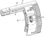
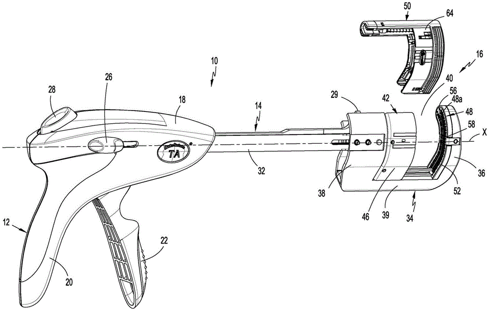
fig. 1 is a side perspective view of a surgical stapling device including a cartridge assembly in accordance with aspects of the present disclosure, wherein the cartridge assembly is separated from a clip slide assembly of the surgical stapling device;
FIG. 2 is a side perspective exploded view of the cartridge assembly shown in FIG. 1;
FIG. 3 is a side perspective view of a cartridge assembly of the surgical stapling apparatus shown in FIG. 1;
FIG. 4 is an enlarged view of the area indicated in detail shown in FIG. 3;
FIG. 5 is a side perspective view of the biasing member of the cartridge assembly shown in FIG. 4 in an unbiased condition;
FIG. 6 is a side perspective view of the biasing member shown in FIG. 5 in an installed state;
FIG. 7 is a side perspective view of an alternate version of the biasing member shown in FIG. 6 in an unbiased condition;
FIG. 8 is a side view of the cartridge assembly shown in FIG. 2 in a pre-fired state with the cartridge body of the cartridge assembly shown in phantom;
FIG. 8A is a side view of the cartridge assembly shown in FIG. 2 in a fired state with the staple pusher and knife carriage in advanced positions and the cartridge body of the cartridge assembly shown in phantom;
FIG. 9 is a side view of the cartridge assembly of FIG. 2 in a fired and retracted state with the cartridge body of the cartridge assembly shown in phantom;
FIG. 10 is a cross-sectional view taken along section line 10-10 of FIG. 9; and
fig. 11 is a side view of the cartridge assembly shown in fig. 2 in a post-fired and retracted state, with the cartridge body of the cartridge assembly shown in phantom, and with a force applied to the knife assembly of the cartridge assembly in a distal direction.
Detailed Description
The disclosed cartridge assembly will now be described in detail with reference to the drawings, in which like reference numerals designate identical or corresponding elements in each of the several views. However, it should be understood that aspects of the present disclosure are merely examples of the present disclosure and may be embodied in various forms. Well-known functions or constructions are not described in detail to avoid obscuring the disclosure in unnecessary detail. Therefore, specific structural and functional details disclosed herein are not to be interpreted as limiting, but merely as a basis for the claims and as a representative basis for teaching one skilled in the art to variously employ the present disclosure in virtually any appropriately detailed structure. Further, directional terms such as anterior, posterior, superior, inferior, top, bottom, distal, proximal, and the like are used to aid in understanding the description, and are not intended to limit the disclosure.
In this specification, the term "proximal" is generally used to refer to the portion of the device that is closer to the clinician during usage of the device, while the term "distal" is generally used to refer to the portion of the device that is further from the clinician during usage of the device. Further, the term "clinician" is commonly used to refer to medical personnel including doctors, nurses, and support personnel.
Fig. 1-3 illustrate the disclosed surgical stapling apparatus, shown generally as stapling apparatus 10. The anastomosis device 10 includes a handle assembly 12, an elongate body 14 extending distally from the handle assembly 12, and a tool assembly 16 supported on a distal portion of the elongate body 14. The elongated body 14 defines a longitudinal axis "X" (fig. 1). The handle assembly 12 includes a housing 18 that defines a fixed handle 20 and supports a movable trigger 22. In aspects of the present disclosure, a movable trigger 22 is supported by the housing 18 to pivot between a non-actuated position and an actuated position toward the stationary handle 20 to operate the tool assembly 16. The handle assembly 12 supports buttons 26 (only one shown) on each side of the housing 18 that are movable along the housing 18 to advance and retract an alignment pin pusher 29 (fig. 3). The handle assembly 12 also includes a release button 28 that can be depressed to move the tool assembly 16 from the clamped position to the undamped position. For a more detailed description of a suitable handle assembly 12, see, for example, U.S. patent No. 6,817,508 ("the' 508 patent").
The anastomosis device 10 includes a frame 32 (fig. 1) extending from the handle assembly 12 to the tool assembly 16. The frame 32 includes a distal frame portion 34 having a U-shaped configuration. The distal frame portion 34 (fig. 3) has a first transverse portion 36, a second transverse portion 38, and a longitudinal portion 39 interconnecting the first and second transverse portions 36, 38. The first and second lateral portions 36, 38 are spaced apart from one another to define a gap 40 extending between the first and second lateral portions 36, 38. In some aspects of the present disclosure, the first and second transverse portions 36, 38 are curved along an axis transverse to the longitudinal axis "X" of the elongated body 14 of the anastomosis device 10. Alternatively, the first and second lateral portions 36, 38 may be linear or include a plurality of linear portions positioned at an angle relative to one another.
The anastomosis device 10 includes a clip slide assembly 42 (fig. 1) having a distal cartridge support member 46 positioned within the gap 40 of the distal frame portion 34 and a proximal portion coupled to the handle assembly 12. The clamp slide assembly 42 is movable between a retracted position and an advanced position in response to actuation of the movable trigger 22.
Tool assembly 16 includes anvil assembly 48 and cartridge assembly 50. Anvil assembly 48 is secured to first transverse portion 36 of distal frame portion 34 of frame 32 and includes an anvil 48a (fig. 1) having a staple deforming surface 52. Staple deforming surface 52 defines an upper opening 56 and a knife channel 58.
Fig. 2-4 show the cartridge assembly 50 removably supported on the distal cartridge support 46 of the clamp slide assembly 42. The cartridge assembly 50 includes a cartridge body 64, staple pushers 66, a knife block 68, and alignment pins 70. The cartridge body 64 defines a cavity 76 (FIG. 2), a tissue engaging surface 64a (FIG. 8), a knife channel 78 (FIG. 10), a plurality of staple channels 80 (FIG. 10), and a plurality of staples 82. The knife channel 78 and staple channel 80 extend through the tissue engaging surface 64a of the cartridge body 64 and communicate with the cavity 76. The cavity 76 receives the staple pusher 66 and the knife block 68 for movement between the retracted position and the advanced position. Staple pusher 66 defines knife channel 72 and contains fingers 84. The fingers 84 are received within the staple slots 80 (fig. 10) such that movement of the staple pusher 80 from its retracted position to its advanced position ejects the staples 82 from the staple slots 80.
The cartridge assembly 60 includes a blade 68a (fig. 2) that is secured to the tool holder 68 and aligned with the knife slot 78 (fig. 10) in the cartridge body 64 and the knife slot 72 in the staple pusher 66. The knife block 68 is movable within the chamber 76 (fig. 2) of the cartridge body 64 from a retracted position to an advanced position to move the knife blade 68a through the knife channel 72 of the staple pusher 66 from the retracted position shielded within the cartridge body 64 to the advanced position protruding from the knife channel 78 of the cartridge body 64. The cartridge body 64 also includes a proximal extension 86 (fig. 2) that receives and surrounds the alignment pin 70. Alignment pin 70 is movable from a retracted position within proximal extension 86 to an advanced position engaged within opening 56 in anvil 48a of anvil assembly 48 to restrain tissue within gap 40 of distal frame portion 34, as is known in the art.
Fig. 2-8 show the cartridge assembly 50 including the biasing member 90. A biasing member 90 is supported on knife block 68 between knife block 68 and the proximal side of staple pusher 66 (fig. 8). In some aspects of the present disclosure, the tool holder 68 defines a recess 92 that receives the biasing member 90, and the biasing member 90 comprises a torsion spring having a central coil 94. The cartridge body 64 includes a post 96 positioned within the recess 92. The center coil 94 defines a hole 94a that receives the post 92 such that the center coil 94 is positioned around the post 92 to secure the torsion spring 90 within the recess 92. Torsion spring 90 includes two spring arms 98 and 100. The first spring arm 98 engages a wall 102 (fig. 2) of the tool holder 68 defining the recess 92. The second spring arm 100 engages the proximal portion 67 of the staple pusher 66. In some aspects of the present disclosure, the ends of each of spring arms 98 and 100 include loops 98a and 100a, respectively. The ring members 98a and 100a provide gripping surfaces to simplify loading of the torsion spring 90 into the cartridge assembly 50 during assembly of the cartridge assembly 50. The ring members 98a and 100a also provide smooth surfaces for engaging the tool post 68 and staple pusher 66, respectively. In some aspects of the present disclosure, one of the ring members 100a has a diameter that is greater than a diameter of the other ring member 98 a. When a large load is applied to the tool holder 68, the larger ring member 100a acts as a spacer between the tool holder 68 and the staple pusher 66. More specifically, the larger ring member 100a has a diameter large enough to prevent the blade 86 from protruding through the knife channel 78 in the cartridge body 64 when the larger ring member 100a is positioned between the knife block 68 and the staple pusher 66 is in its advanced position. The tool holder 68 includes stops 106 and 108 (fig. 8) that hang over the recess 92 to retain the torsion spring 90 within the recess 92.
As shown in FIG. 5, the ring members 98a and 100a are spaced apart from one another in their unbiased condition. In the compressed state, i.e., when the biasing member 90 is compressed between the knife block 68 and the staple pusher 66, the second spring arm 100 deforms toward the first spring arm 98 in the direction indicated by arrow "a" in fig. 6.
Although the biasing member 90 is illustrated in fig. 2-6 as a torsion spring 90, it is contemplated that the biasing member 90 may be formed having a variety of different spring configurations and different spring types. For example, the biasing member may be formed as a leaf spring 90' as shown in FIG. 7. The blade spring 90' includes a first spring arm 98' and a second spring arm 100'. Each of the spring arms 98 'and 100' includes a ring member 98a 'and 100a', respectively. Spring arms 98a 'and 100a' function in the same manner as ring members 98a and 100a (fig. 6) described above. A bend or curved portion 110' is positioned between first spring arm 98' and second spring arm 100'. The bend 110 'provides the leaf spring 90' with a greater degree of flexibility.
Fig. 2 and 3 illustrate the cartridge body 64 defining an elongated window 112 that is aligned with the recess 92 in the tool holder 68 when the tool holder 68 is in its retracted position. The window 112 allows the biasing member 90 to be compressed and inserted into the recess 92 of the tool holder 68. Biasing member 90 must be compressed sufficiently to allow spring arms 98 and 100 to pass stops 106 and 108 (fig. 8). As biasing member 90 passes stops 106 and 108, spring arms 98 and 100 move to a position below stops 106 and 108 to prevent biasing member 90 from falling out of recess 92.
Fig. 8 shows the cartridge assembly 60 in a pre-firing position. In the pre-firing position, the knife block 68 and staple pusher 66 are in a retracted position within the cartridge body 64. In their retracted positions, the biasing members 90 are compressed between the proximal portion 67 of the staple pusher 66 and the wall 102 of the knife block 68, with the ring member 98a of the first spring arm 98 engaged with the knife block 68 and the ring member 100a of the second spring arm 100 engaged with the staple pusher 66. The fingers 84 of the staple pusher 66 are aligned with the staples 82 in the staple slots 80 of the cartridge body 64 and the blade 68a is recessed within the knife channel 78 (FIG. 10) of the cartridge body 64.
FIG. 8A illustrates the cartridge assembly 50 after the stapling apparatus 10 (FIG. 1) has been fired with the knife block 68 and staple pusher 66 in their advanced positions. When the cartridge assembly 50 is fired to move the knife block 68 and staple cartridge 66 to their advanced positions within the cartridge body 64, the knife block 68 engages the staple pusher 66 and pushes the staple pusher 66 to its advanced position when the knife block 68 is moved to its advanced position. When the staple pusher 66 is moved to its advanced position, the fingers 84 move through the staple slots 80 of the cartridge body 64 to eject the staples 82 from the staple slots 80. When knife block 68 is moved to its advanced position, blade 68a moves through knife slot 78 and extends from cartridge body 64 into anvil assembly 48 (fig. 1) to cut tissue clamped between anvil assembly 48 and cartridge assembly 50.
Fig. 9 and 10 illustrate the cartridge assembly 50 after the cartridge assembly 50 is fired and the knife block 68 is retracted. When the knife block 68 is retracted in the direction of arrow "B" in fig. 9, the staple pusher 66 remains in its advanced position with the finger 84 positioned within the staple channel 80 of the cartridge body 64 (fig. 10) and the blade 68a retracted into the knife channel 78 of the cartridge body 64. As the knife block 68 moves proximally relative to the staple pusher 66, the second spring arm 100 springs outwardly in the direction of arrow "C" in fig. 9 such that the ring member 100a of the second spring arm 100 remains engaged with the staple pusher 66 until the knife block 68 approaches its fully retracted position. In the fully retracted position of the tool block 68, the ring member 100a of the spring arm 100 is spaced from the staple pusher 66. As the knife block 68 moves proximally relative to the staple pusher 66, the spring arm 98a remains engaged with the knife block 68. In this position, the second spring arm 100 moves from within the recess 92 in the cartridge 68 to a position laterally offset from the recess 92, and the biasing member 90 blocks advancement of the cartridge body 64 of the cartridge 68 to prevent re-exposure of the blade 68 a.
Fig. 11 shows the cartridge assembly 50 after the cartridge assembly 50 has been fired and the knife carriage 68 has been retracted due to the application of force to the knife carriage 68 in the distal direction indicated by arrow "D" to move the knife carriage 68 and blade 68a toward their advanced position. When sufficient force is applied to the knife block 68 to advance the knife block 68 and knife blade 68a toward their advanced positions after the device 10 has been fired, the ring member 100a, which is misaligned with the recess 92, bends the second spring arm 100 toward the knife block 68 such that the ring member 100a of the second spring arm 100 is positioned between the staple pusher 66 and the knife block 68. By positioning the ring member 100a of the second spring arm 100 between the knife block 68 and the staple pusher 66, the knife block 68 is prevented from advancing to a position where the blade 68a (fig. 10) is re-exposed through the knife slot 78.
Those skilled in the art will appreciate that the devices and methods specifically described herein and illustrated in the accompanying drawings are non-limiting exemplary aspects of the present disclosure. It is envisioned that elements and features shown or described in connection with one exemplary embodiment may be combined with elements and features of another exemplary embodiment without departing from the scope of the present disclosure. Also, based on the above aspects of the disclosure, one skilled in the art will appreciate further features and advantages of the disclosure. Accordingly, the disclosure is not to be limited by what has been particularly shown and described, except as indicated by the appended claims.
Claims (20)
1. A cartridge assembly, comprising:
a cartridge body defining a cavity, a knife channel, a plurality of staple channels, and a tissue engaging surface, the knife channel and the plurality of staple channels extending between the tissue engaging surface and the cavity;
a plurality of staples, each staple of said plurality of staples being received within one of said plurality of staple slots;
a staple pusher supported within the cavity of the cartridge body, the staple pusher being movable from a retracted position to an advanced position to eject the plurality of staples from the plurality of staple pockets of the cartridge body;
a blade carrier supporting a blade, the blade carrier positioned within the cavity of the cartridge body and movable between a retracted position and an advanced position to move the blade from a retracted position recessed within the cartridge body to an advanced position protruding from the knife slot; and
a biasing member positioned within the cartridge body between the knife carriage and the staple pusher, the biasing member configured to urge the knife carriage and the blade toward their retracted positions.
2. The cartridge assembly of claim 1 wherein said knife block defines a recess within which said biasing member is received when said knife block and said staple pusher are in their retracted positions.
3. The cartridge assembly of claim 2 wherein said biasing member includes a first spring arm engaged with said knife block and a second spring arm engaged with said staple pusher.
4. The cartridge assembly of claim 3 wherein said first spring arm includes a first ring member engaged with said knife block and said second spring arm includes a second ring member engaged with said staple pusher.
5. The cartridge assembly of claim 4 wherein the second spring arm is longitudinally misaligned with the recess when the staple pusher is in its advanced position and the knife block is in its retracted position.
6. The cartridge assembly of claim 3 wherein the biasing member includes a torsion spring.
7. The cartridge assembly of claim 6 wherein the torsion spring includes a central coil positioned between the first spring arm and the second spring arm.
8. The cartridge assembly of claim 7, wherein the cartridge body includes a post positioned within the recess, the post received within the central coil of the torsion spring.
9. The cartridge assembly of claim 2 wherein said biasing member includes a first spring arm and a second spring arm, said first spring arm engaged with said knife carriage and said second spring arm including a ring member engaged with said staple pusher, said ring member positioned within said recess when said staple pusher and said knife carriage are in their retracted positions, and said ring member positioned between said staple pusher and said knife carriage out of alignment with said recess when said staple pusher is in its advanced position and said knife carriage is in its retracted position.
10. The cartridge assembly of claim 9 wherein the ring member has a diameter for inhibiting advancement of a blade from the knife slot when the ring member is misaligned with the recess.
11. The cartridge assembly of claim 3 wherein the biasing member includes a leaf spring.
12. The cartridge assembly of claim 11 wherein the blade spring includes a bend defined between the first spring arm and the second spring arm.
13. A cartridge assembly, comprising:
a cartridge body defining a cavity, a knife channel, a plurality of staple channels, and a tissue engaging surface, the knife channel and the plurality of staple channels extending between the tissue engaging surface and the cavity;
a plurality of staples, each staple of said plurality of staples being received within one of said plurality of staple slots;
a staple pusher supported within the cavity of the cartridge body, the staple pusher being movable from a retracted position to an advanced position to eject the plurality of staples from the plurality of staple pockets of the cartridge body;
a blade carrier supporting a blade, the blade carrier positioned within the cavity of the cartridge body and movable between a retracted position and an advanced position to move the blade from a retracted position recessed within the cartridge body to an advanced position protruding from the knife slot; and
a biasing member positioned within the cartridge body between the knife carrier and the staple pusher, the biasing member including a first spring arm and a second spring arm, the first spring arm engaged with the knife carrier and the second spring arm engaged with the staple pusher to urge the knife carrier and the blade toward their retracted positions, the second spring arm including a ring member engaged with the staple pusher, the ring member positioned between the staple pusher and the knife carrier when the staple pusher is in its advanced position and the knife carrier is in its retracted position.
14. A surgical stapling device, comprising:
a handle assembly;
a frame comprising a U-shaped distal frame portion comprising a first transverse portion, a second transverse portion, and a longitudinal portion connecting the first and second transverse portions, the first and second transverse portions defining a gap;
an anvil supported on the first lateral portion;
a clip slide assembly including a distal cartridge support positioned within the gap; and
a cartridge assembly supported on the distal cartridge support of the clamp slide assembly, the cartridge assembly including:
a cartridge body defining a cavity, a knife channel, a plurality of staple channels, and a tissue engaging surface, the knife channel and the plurality of staple channels extending between the tissue engaging surface and the cavity;
a plurality of staples, each staple of said plurality of staples being received within one of said plurality of staple slots;
a staple pusher supported within the cavity of the cartridge body, the staple pusher being movable from a retracted position to an advanced position to eject the plurality of staples from the plurality of staple pockets of the cartridge body;
a blade carrier supporting a blade, the blade carrier positioned within the cavity of the cartridge body and movable between a retracted position and an advanced position to move the blade from a retracted position recessed within the cartridge body to an advanced position protruding from the knife slot; and
a biasing member positioned within the cartridge body between the knife carrier and the staple pusher, the biasing member configured to urge the knife carrier and the blade toward their retracted positions.
15. The surgical stapling device of claim 14 wherein the knife block defines a recess within which the biasing member is received when the knife block and the staple pusher are in their retracted positions.
16. The surgical stapling device of claim 14, wherein the biasing member includes a first spring arm engaged with the knife block and a second spring arm engaged with the staple pusher.
17. The surgical stapling device of claim 16, wherein the first spring arm includes a first ring member engaged with the knife block and the second spring arm includes a second ring member engaged with the staple pusher.
18. The surgical stapling device of claim 16, wherein the biasing member includes a torsion spring.
19. The surgical stapling device of claim 16, wherein the biasing member comprises a leaf spring.
20. The surgical stapling device of claim 16 wherein the knife block defines a recess within which the biasing member is received when the knife block and the staple pusher are in their retracted positions, the second spring arm including a ring member engaged with the staple pusher, the ring member being positioned within the recess when the staple pusher and the knife block are in their retracted positions, and the ring member being positioned between the staple pusher and the knife block out of alignment with the recess when the staple pusher is in its advanced position and the knife block is in its retracted position.
Applications Claiming Priority (1)
| Application Number | Priority Date | Filing Date | Title |
|---|---|---|---|
| PCT/CN2020/077059 WO2021168761A1 (en) | 2020-02-28 | 2020-02-28 | Staple cartridge with retractable knife assembly |
Publications (1)
| Publication Number | Publication Date |
|---|---|
| CN115175624A true CN115175624A (en) | 2022-10-11 |
Family
ID=77489764
Family Applications (1)
| Application Number | Title | Priority Date | Filing Date |
|---|---|---|---|
| CN202080097614.XA Pending CN115175624A (en) | 2020-02-28 | 2020-02-28 | Nail bin with retractable knife assembly |
Country Status (5)
| Country | Link |
|---|---|
| US (1) | US12458350B2 (en) |
| EP (1) | EP4110194A4 (en) |
| JP (1) | JP2023524348A (en) |
| CN (1) | CN115175624A (en) |
| WO (1) | WO2021168761A1 (en) |
Families Citing this family (2)
| Publication number | Priority date | Publication date | Assignee | Title |
|---|---|---|---|---|
| CA216658S (en) * | 2022-04-08 | 2023-12-08 | Cilag Gmbh Int | Surgical staple cartridge |
| JP1740379S (en) * | 2022-04-08 | 2023-03-31 | surgical stapler cartridge |
Citations (10)
| Publication number | Priority date | Publication date | Assignee | Title |
|---|---|---|---|---|
| CN102599954A (en) * | 2012-03-31 | 2012-07-25 | 常州市康迪医用吻合器有限公司 | Linear cutting anastomat with double security mechanisms |
| US20130098966A1 (en) * | 2011-10-25 | 2013-04-25 | Stanislaw Kostrzewski | Apparatus for Endoscopic Procedures |
| US20130313305A1 (en) * | 2012-05-25 | 2013-11-28 | Tyco Healthcare Group Lp | Surgical Fastener Applying Apparatus Including Replaceable Cartridge Assembly |
| CN203970458U (en) * | 2014-07-09 | 2014-12-03 | 苏州天臣国际医疗科技有限公司 | Anastomat and for the nail bin groupware of this anastomat |
| CN204016394U (en) * | 2014-04-04 | 2014-12-17 | 苏州天臣国际医疗科技有限公司 | Nail bin groupware and there is the anastomat of this nail bin groupware |
| CN104546040A (en) * | 2013-10-17 | 2015-04-29 | 柯惠Lp公司 | Surgical instrument, loading unit and fasteners for use therewith |
| CN207186650U (en) * | 2017-02-27 | 2018-04-06 | 苏州法兰克曼医疗器械有限公司 | A kind of surgical incision anastomat |
| US20180153544A1 (en) * | 2016-12-02 | 2018-06-07 | Covidien Lp | Surgical stapling instrument with curved end effector |
| CN108472037A (en) * | 2015-12-31 | 2018-08-31 | 伊西康有限责任公司 | Surgical stapling device with the variable height driver for consistent nail forming |
| CN114727818A (en) * | 2019-11-01 | 2022-07-08 | 柯惠有限合伙公司 | Surgical Stapling Device with Blade Lock |
Family Cites Families (163)
| Publication number | Priority date | Publication date | Assignee | Title |
|---|---|---|---|---|
| US1158111A (en) | 1914-10-07 | 1915-10-26 | Edward C Ahlheim | Rolling-pin. |
| US2891250A (en) | 1956-10-15 | 1959-06-23 | Hirata Yasuhiro | Bronchus seaming instrument |
| US3080564A (en) | 1959-09-10 | 1963-03-12 | Strekopitov Alexey Alexeevich | Instrument for stitching hollow organs |
| US3252643A (en) | 1962-12-24 | 1966-05-24 | Strekopytov Alexey Alexcevich | Instrument for suturing living tissue |
| US3269630A (en) | 1964-04-30 | 1966-08-30 | Fleischer Harry | Stapling instrument |
| US3275211A (en) | 1965-05-10 | 1966-09-27 | United States Surgical Corp | Surgical stapler with replaceable cartridge |
| US3315863A (en) | 1965-07-06 | 1967-04-25 | United States Surgical Corp | Medical instrument |
| US3494533A (en) | 1966-10-10 | 1970-02-10 | United States Surgical Corp | Surgical stapler for stitching body organs |
| DE1791114B1 (en) | 1967-09-19 | 1971-12-02 | Vnii Chirurgitscheskoj Apparat | Surgical device for stapling tissues |
| BE758685A (en) | 1970-10-14 | 1971-05-10 | Vnii Khirurgicheskoi Apparatur | SURGICAL APPARATUS FOR TISSUE SUTURE WITH STAPLES |
| GB1374002A (en) | 1971-05-03 | 1974-11-13 | Vnii Khirurgicheskoi Apparatur | Surgical instrument for suturing tissues and organs with metal staples |
| US3822818A (en) | 1973-02-20 | 1974-07-09 | A Strekopytov | Surgical instrument for joining osseous tissues by staples |
| SU506963A1 (en) | 1973-07-26 | 1976-08-25 | Всесоюзный Научно-Исследовательский И Испытательный Институт Медицинской Техники Министерства Здравоохранения Ссср | Surgical stapler |
| SU449524A1 (en) | 1973-07-31 | 1976-05-15 | Всесоюзный научно-исследовательский и испытательный институт медицинской техники | Surgical apparatus for cross-linking of organs |
| US4047654A (en) | 1976-06-23 | 1977-09-13 | Alfredo Alvarado | Surgical stapler |
| SU1036324A1 (en) | 1978-03-31 | 1983-08-23 | Всесоюзный научно-исследовательский и испытательный институт медицинской техники | Surgical suturing device |
| US4216891A (en) | 1979-02-12 | 1980-08-12 | Behlke Harold O | Surgical stapler |
| SU886900A1 (en) | 1979-03-26 | 1981-12-07 | Всесоюзный научно-исследовательский и испытательный институт медицинской техники | Surgical apparatus for applying line sutures |
| SU942719A1 (en) | 1979-11-23 | 1982-07-15 | Всесоюзный научно-исследовательский и испытательный институт медицинской техники | Surgical suturing apparatus for application of linear sutures |
| US4485811A (en) | 1980-02-08 | 1984-12-04 | Vsesojuzny Nauchny Tsentr Khirurgii | Resection apparatus |
| US4296881A (en) | 1980-04-03 | 1981-10-27 | Sukoo Lee | Surgical stapler using cartridge |
| US4378901A (en) | 1980-05-22 | 1983-04-05 | Akopov Ernest M | Apparatus for applying a staple suture |
| US4354628A (en) | 1980-09-29 | 1982-10-19 | United States Surgical Corporation | Surgical stapler apparatus having pivotally related staple holder and anvil |
| US4402444A (en) | 1981-04-20 | 1983-09-06 | United States Surgical Corporation | Surgical stapling instrument with automatic frame reinforcement |
| US4383634A (en) | 1981-05-26 | 1983-05-17 | United States Surgical Corporation | Surgical stapler apparatus with pivotally mounted actuator assemblies |
| US4475679A (en) | 1981-08-07 | 1984-10-09 | Fleury Jr George J | Multi-staple cartridge for surgical staplers |
| US4632290A (en) | 1981-08-17 | 1986-12-30 | United States Surgical Corporation | Surgical stapler apparatus |
| US4415112A (en) | 1981-10-27 | 1983-11-15 | United States Surgical Corporation | Surgical stapling assembly having resiliently mounted anvil |
| US4442964A (en) | 1981-12-07 | 1984-04-17 | Senco Products, Inc. | Pressure sensitive and working-gap controlled surgical stapling instrument |
| US4470533A (en) | 1982-08-13 | 1984-09-11 | Ethicon, Inc. | Surgical instrument for suturing tissues and organs |
| US4506671A (en) | 1983-03-30 | 1985-03-26 | United States Surgical Corporation | Apparatus for applying two-part surgical fasteners |
| US4506670A (en) | 1983-03-30 | 1985-03-26 | United States Surgical Corporation | Two-part surgical fastener applying apparatus with frangible member |
| US4522327A (en) | 1983-05-18 | 1985-06-11 | United States Surgical Corporation | Surgical fastener applying apparatus |
| USD273513S (en) | 1983-06-10 | 1984-04-17 | Senco Products, Inc. | Linear surgical stapling instrument |
| US4527724A (en) | 1983-06-10 | 1985-07-09 | Senmed, Inc. | Disposable linear surgical stapling instrument |
| US4602634A (en) | 1983-09-23 | 1986-07-29 | Ethicon, Inc. | Method and instrument for applying a fastener to a tissue using means to grasp, guide and pull the fastener through the tissue |
| US4530453A (en) | 1983-10-04 | 1985-07-23 | United States Surgical Corporation | Surgical fastener applying apparatus |
| US4508253A (en) | 1983-10-04 | 1985-04-02 | United States Surgical Corporation | Surgical fastener applying apparatus |
| US4568009A (en) | 1984-01-20 | 1986-02-04 | United States Surgical Corporation | Surgical fastener applying apparatus |
| US4550870A (en) | 1983-10-13 | 1985-11-05 | Alchemia Ltd. Partnership | Stapling device |
| US4612933A (en) | 1984-03-30 | 1986-09-23 | Senmed, Inc. | Multiple-load cartridge assembly for a linear surgical stapling instrument |
| US4585153A (en) | 1984-07-16 | 1986-04-29 | Ethicon, Inc. | Surgical instrument for applying two-piece fasteners comprising frictionally held U-shaped staples and receivers (Case III) |
| US4606344A (en) | 1984-07-16 | 1986-08-19 | Ethicon, Inc. | Surgical instrument for applying fasteners having improved gap indicating means (Case V) |
| US4607636A (en) | 1984-07-16 | 1986-08-26 | Ethicon, Inc. | Surgical instrument for applying fasteners having tissue locking means for maintaining the tissue in the instrument while applying the fasteners (case I) |
| US4605004A (en) | 1984-07-16 | 1986-08-12 | Ethicon, Inc. | Surgical instrument for applying fasteners said instrument including force supporting means (case IV) |
| US4606345A (en) | 1984-07-16 | 1986-08-19 | Ethicon, Inc. | Surgical instrument for applying two-piece fasteners comprising U-shaped staples and frictionally held receivers (Case II) |
| US4589582A (en) | 1984-08-23 | 1986-05-20 | Senmed, Inc. | Cartridge and driver assembly for a surgical stapling instrument |
| US4617928A (en) | 1984-09-17 | 1986-10-21 | Alfranca Jose Maria P | Surgical instrument for practicing mechanical sutures and biopsies |
| US4566620A (en) | 1984-10-19 | 1986-01-28 | United States Surgical Corporation | Articulated surgical fastener applying apparatus |
| US4573622A (en) | 1984-10-19 | 1986-03-04 | United States Surgical Corporation | Surgical fastener applying apparatus with variable fastener arrays |
| US4767044A (en) | 1984-10-19 | 1988-08-30 | United States Surgical Corporation | Surgical fastener applying apparatus |
| US4580712A (en) | 1984-10-19 | 1986-04-08 | United States Surgical Corporation | Surgical fastener applying apparatus with progressive application of fastener |
| US4605001A (en) | 1984-10-19 | 1986-08-12 | Senmed, Inc. | Surgical stapling instrument with dual staple height mechanism |
| US4665916A (en) | 1985-08-09 | 1987-05-19 | United States Surgical Corporation | Surgical stapler apparatus |
| US4728020A (en) | 1985-08-30 | 1988-03-01 | United States Surgical Corporation | Articulated surgical fastener applying apparatus |
| SE457228B (en) | 1985-09-10 | 1988-12-12 | Vnii Ispytatel Med Tech | SURGICAL INSTRUMENT FOR APPLICATION OF LINERABLE HANGING SEWINGS |
| US4715520A (en) | 1985-10-10 | 1987-12-29 | United States Surgical Corporation | Surgical fastener applying apparatus with tissue edge control |
| US4802614A (en) | 1986-05-23 | 1989-02-07 | United States Surgical Corporation | Surgical stapling instrument and cartridge |
| US4714187A (en) | 1986-11-26 | 1987-12-22 | United States Surgical Corporation | Reloading unit for surgical fastening instruments |
| US4941623A (en) | 1987-05-12 | 1990-07-17 | United States Surgical Corporation | Stapling process and device for use on the mesentery of the abdomen |
| US4848637A (en) | 1987-06-11 | 1989-07-18 | Pruitt J Crayton | Staple device for use on the mesenteries of the abdomen |
| US4930503A (en) | 1987-06-11 | 1990-06-05 | Pruitt J Crayton | Stapling process and device for use on the mesenteries of the abdomen |
| US4819853A (en) | 1987-12-31 | 1989-04-11 | United States Surgical Corporation | Surgical fastener cartridge |
| GB8800909D0 (en) | 1988-01-15 | 1988-02-17 | Ethicon Inc | Gas powered surgical stapler |
| US4805823A (en) | 1988-03-18 | 1989-02-21 | Ethicon, Inc. | Pocket configuration for internal organ staplers |
| US5071052A (en) | 1988-09-22 | 1991-12-10 | United States Surgical Corporation | Surgical fastening apparatus with activation lockout |
| US4881545A (en) | 1988-12-08 | 1989-11-21 | United States Surgical Corporation | Surgical fastener cartridge with improved body tissue cutting knife assembly |
| US4881544A (en) | 1988-12-19 | 1989-11-21 | United States Surgical Corporation | Surgical stapler apparatus with improved tissue shield |
| US4915100A (en) | 1988-12-19 | 1990-04-10 | United States Surgical Corporation | Surgical stapler apparatus with tissue shield |
| US5100042A (en) | 1990-03-05 | 1992-03-31 | United States Surgical Corporation | Surgical fastener apparatus |
| US5005754A (en) | 1990-04-04 | 1991-04-09 | Ethicon, Inc. | Bladder and mandrel for use with surgical stapler |
| US5116349A (en) | 1990-05-23 | 1992-05-26 | United States Surgical Corporation | Surgical fastener apparatus |
| CA2052176A1 (en) | 1990-10-05 | 1992-04-06 | Daniel P. Rodak | Controlled closure mechanism |
| CA2055943C (en) | 1990-12-06 | 2003-09-23 | Daniel P. Rodak | Surgical fastening apparatus with locking mechanism |
| US5470009A (en) | 1990-12-06 | 1995-11-28 | United States Surgical Corporation | Surgical fastening apparatus with locking mechanism |
| US5571285A (en) | 1991-02-19 | 1996-11-05 | Ethicon, Inc. | Surgical staple for insertion into tissue |
| US5219111A (en) | 1991-03-11 | 1993-06-15 | Ethicon, Inc. | Pneumatically actuated linear stapling device |
| US5172845A (en) | 1991-04-12 | 1992-12-22 | Tejeiro William V | Right angle articulated intestinal stapler |
| AU671685B2 (en) | 1991-05-14 | 1996-09-05 | United States Surgical Corporation | Surgical stapler with spent cartridge sensing and lockout means |
| US5413267A (en) | 1991-05-14 | 1995-05-09 | United States Surgical Corporation | Surgical stapler with spent cartridge sensing and lockout means |
| US5137198A (en) | 1991-05-16 | 1992-08-11 | Ethicon, Inc. | Fast closure device for linear surgical stapling instrument |
| AU660712B2 (en) | 1991-10-18 | 1995-07-06 | United States Surgical Corporation | Apparatus for applying surgical fasteners |
| ES2041610T3 (en) | 1991-10-18 | 1997-05-16 | United States Surgical Corp | APPARATUS TO APPLY SURGICAL FASTENING CLAMPS. |
| US5579978A (en) | 1991-10-18 | 1996-12-03 | United States Surgical Corporation | Apparatus for applying surgical fasteners |
| CA2078794C (en) | 1991-10-18 | 1998-10-06 | Frank J. Viola | Locking device for an apparatus for applying surgical fasteners |
| US5240163A (en) | 1991-10-30 | 1993-08-31 | American Cyanamid Company | Linear surgical stapling instrument |
| US5368599A (en) | 1992-10-08 | 1994-11-29 | United States Surgical Corporation | Surgical fastening apparatus with suture array |
| US5503320A (en) | 1993-08-19 | 1996-04-02 | United States Surgical Corporation | Surgical apparatus with indicator |
| US5542594A (en) | 1993-10-06 | 1996-08-06 | United States Surgical Corporation | Surgical stapling apparatus with biocompatible surgical fabric |
| US5439155A (en) | 1993-10-07 | 1995-08-08 | United States Surgical Corporation | Cartridge for surgical fastener applying apparatus |
| US5465894A (en) | 1993-12-06 | 1995-11-14 | Ethicon, Inc. | Surgical stapling instrument with articulated stapling head assembly on rotatable and flexible support shaft |
| US5405073A (en) | 1993-12-06 | 1995-04-11 | Ethicon, Inc. | Flexible support shaft assembly |
| US5470008A (en) | 1993-12-20 | 1995-11-28 | United States Surgical Corporation | Apparatus for applying surgical fasteners |
| US5452836A (en) | 1994-02-07 | 1995-09-26 | Ethicon Endo-Surgery, Inc. | Surgical stapling instrument with improved jaw closure and staple firing actuator mechanism |
| WO1995023557A1 (en) | 1994-03-01 | 1995-09-08 | United States Surgical Corporation | Surgical stapler with anvil sensor and lockout |
| CA2145723A1 (en) | 1994-03-30 | 1995-10-01 | Steven W. Hamblin | Surgical stapling instrument with remotely articulated stapling head assembly on rotatable support shaft |
| US5735445A (en) | 1995-03-07 | 1998-04-07 | United States Surgical Corporation | Surgical stapler |
| US5678748A (en) | 1995-05-24 | 1997-10-21 | Vir Engineering | Surgical stapler with improved safety mechanism |
| US5641111A (en) | 1995-06-28 | 1997-06-24 | Ethicon Endo-Surgery, Inc. | Surgical stapling instrument with anvil cutting guide |
| US5706998A (en) | 1995-07-17 | 1998-01-13 | United States Surgical Corporation | Surgical stapler with alignment pin locking mechanism |
| US5697543A (en) | 1996-03-12 | 1997-12-16 | Ethicon Endo-Surgery, Inc. | Linear stapler with improved firing stroke |
| US5605272A (en) | 1996-03-12 | 1997-02-25 | Ethicon Endo-Surgery, Inc. | Trigger mechanism for surgical instruments |
| US5810240A (en) | 1996-03-15 | 1998-09-22 | United States Surgical Corporation | Surgical fastener applying device |
| US6805273B2 (en) | 2002-11-04 | 2004-10-19 | Federico Bilotti | Surgical stapling instrument |
| US6817508B1 (en) | 2000-10-13 | 2004-11-16 | Tyco Healthcare Group, Lp | Surgical stapling device |
| US7407076B2 (en) | 2000-10-13 | 2008-08-05 | Tyco Healthcare Group Lp | Surgical stapling device |
| US6638285B2 (en) | 2001-04-16 | 2003-10-28 | Shlomo Gabbay | Biological tissue strip and system and method to seal tissue |
| WO2003086206A1 (en) | 2002-04-11 | 2003-10-23 | Tyco Healthcare Group, Lp | Surgical stapling apparatus including an anvil and cartridge each having cooperating mating surfaces |
| EP1496805B1 (en) | 2002-04-25 | 2012-01-11 | Tyco Healthcare Group LP | Surgical instruments including micro-electromechanical systems (mems) |
| US20060163312A1 (en) | 2002-10-04 | 2006-07-27 | Viola Frank J | Angled surgical fastener apparatus |
| US7147139B2 (en) | 2003-12-30 | 2006-12-12 | Ethicon Endo-Surgery, Inc | Closure plate lockout for a curved cutter stapler |
| US20050143759A1 (en) | 2003-12-30 | 2005-06-30 | Kelly William D. | Curved cutter stapler shaped for male pelvis |
| US7207472B2 (en) | 2003-12-30 | 2007-04-24 | Ethicon Endo-Surgery, Inc. | Cartridge with locking knife for a curved cutter stapler |
| US6988650B2 (en) | 2003-12-30 | 2006-01-24 | Ethicon Endo-Surgery, Inc. | Retaining pin lever advancement mechanism for a curved cutter stapler |
| US7147140B2 (en) | 2003-12-30 | 2006-12-12 | Ethicon Endo - Surgery, Inc. | Cartridge retainer for a curved cutter stapler |
| US7766207B2 (en) | 2003-12-30 | 2010-08-03 | Ethicon Endo-Surgery, Inc. | Articulating curved cutter stapler |
| US7549563B2 (en) | 2003-12-30 | 2009-06-23 | Ethicon Endo-Surgery, Inc. | Rotating curved cutter stapler |
| US7204404B2 (en) | 2003-12-30 | 2007-04-17 | Ethicon Endo-Surgery, Inc. | Slotted pins guiding knife in a curved cutter stapler |
| US7134587B2 (en) | 2003-12-30 | 2006-11-14 | Ethicon Endo-Surgery, Inc. | Knife retraction arm for a curved cutter stapler |
| US7210609B2 (en) | 2004-07-30 | 2007-05-01 | Tools For Surgery, Llc | Stapling apparatus having a curved anvil and driver |
| AU2004323140B2 (en) | 2004-09-10 | 2011-11-24 | Ethicon Endo-Surgery, Inc. | Surgical stapling instrument |
| SI1793742T1 (en) | 2004-09-30 | 2008-08-31 | Ethicon Endo Surgery Inc | Surgical stapling instrument |
| US7340192B2 (en) | 2005-03-16 | 2008-03-04 | Kabushiki Kaisha Toshiba | Fixing device of image forming apparatus |
| US7717312B2 (en) | 2005-06-03 | 2010-05-18 | Tyco Healthcare Group Lp | Surgical instruments employing sensors |
| US7641092B2 (en) | 2005-08-05 | 2010-01-05 | Ethicon Endo - Surgery, Inc. | Swing gate for device lockout in a curved cutter stapler |
| US8579178B2 (en) | 2005-08-15 | 2013-11-12 | Covidien Lp | Surgical stapling instruments including a cartridge having multiple staples sizes |
| US7886953B2 (en) | 2005-08-18 | 2011-02-15 | Ethicon Endo-Surgery, Inc. | Fired device lockout for a curved cutter stapler with a free moving trigger |
| US8029520B2 (en) | 2006-02-07 | 2011-10-04 | Ethicon Endo-Surgery, Inc. | Method for performing trans-anal resection with a curved cutter stapler |
| WO2007093198A1 (en) | 2006-02-15 | 2007-08-23 | Ethicon Endo-Surgery, Inc. | A device, clip, endoscope and method for the intraluminal treatment of tissue, e.g. hemorrhoids |
| US7431190B2 (en) | 2006-03-01 | 2008-10-07 | Ethicon Endo-Surgery, Inc. | Linear stapler with improved firing mechanism |
| US7568605B2 (en) | 2006-03-22 | 2009-08-04 | Ethicon Endo-Surgery, Inc. | Surgical stapler shaft cover |
| EP2015681B1 (en) | 2006-05-03 | 2018-03-28 | Datascope Corp. | Tissue closure device |
| US7552854B2 (en) | 2006-05-19 | 2009-06-30 | Applied Medical Resources Corporation | Surgical stapler with firing lock mechanism |
| ATE462360T1 (en) | 2006-07-07 | 2010-04-15 | Ethicon Endo Surgery Inc | INTRODUCTION SYSTEM FOR A SURGICAL INSTRUMENT |
| ATE440549T1 (en) | 2006-09-08 | 2009-09-15 | Ethicon Endo Surgery Inc | SURGICAL INSTRUMENT AND ACTUATING DEVICE FOR TRANSMITTING MOTION THEREFOR |
| US7721936B2 (en) * | 2007-01-10 | 2010-05-25 | Ethicon Endo-Surgery, Inc. | Interlock and surgical instrument including same |
| US8231041B2 (en) | 2008-04-14 | 2012-07-31 | Tyco Healthcare Group Lp | Variable compression surgical fastener cartridge |
| US8028884B2 (en) | 2008-04-22 | 2011-10-04 | Tyco Healthcare Group Lp | Cartridge for applying varying amounts of tissue compression |
| CA2665017A1 (en) | 2008-05-05 | 2009-11-05 | Tyco Healthcare Group Lp | Surgical instrument with sequential clamping and cutting |
| US8967446B2 (en) | 2008-05-09 | 2015-03-03 | Covidien Lp | Variable compression surgical fastener cartridge |
| US8424738B2 (en) | 2008-06-04 | 2013-04-23 | Covidien Lp | Attachable clamp for surgical stapler |
| US8016176B2 (en) | 2008-06-04 | 2011-09-13 | Tyco Healthcare Group, Lp | Surgical stapling instrument with independent sequential firing |
| US8070038B2 (en) | 2008-10-10 | 2011-12-06 | Tyco Healthcare Group, Lp | Surgical instrument with pivotable jaw member |
| US8353436B2 (en) | 2009-05-06 | 2013-01-15 | Covidien Lp | Pin locking mechanism for a surgical instrument |
| US8328064B2 (en) | 2009-05-06 | 2012-12-11 | Covidien Lp | Pin locking mechanism for a surgical instrument |
| US8276801B2 (en) | 2011-02-01 | 2012-10-02 | Tyco Healthcare Group Lp | Surgical stapling apparatus |
| US8955732B2 (en) | 2009-08-11 | 2015-02-17 | Covidien Lp | Surgical stapling apparatus |
| US8596515B2 (en) | 2010-06-18 | 2013-12-03 | Covidien Lp | Staple position sensor system |
| CN101912284B (en) * | 2010-08-13 | 2012-07-18 | 李东瑞 | Arc-shaped cutting anastomat |
| US8360296B2 (en) | 2010-09-09 | 2013-01-29 | Ethicon Endo-Surgery, Inc. | Surgical stapling head assembly with firing lockout for a surgical stapler |
| US8292150B2 (en) | 2010-11-02 | 2012-10-23 | Tyco Healthcare Group Lp | Adapter for powered surgical devices |
| US8517242B2 (en) | 2011-01-04 | 2013-08-27 | Covidien Lp | Surgical fastener-applying apparatuses with sequential firing |
| CN102835983B (en) | 2011-06-21 | 2016-08-17 | 伊西康内外科公司 | Linear staplers |
| US9675351B2 (en) | 2011-10-26 | 2017-06-13 | Covidien Lp | Buttress release from surgical stapler by knife pushing |
| US9125651B2 (en) | 2011-12-07 | 2015-09-08 | Ethicon Endo-Surgery, Inc. | Reusable linear stapler cartridge device for tissue thickness measurement |
| US9351731B2 (en) | 2011-12-14 | 2016-05-31 | Covidien Lp | Surgical stapling apparatus including releasable surgical buttress |
| BR112014020069B1 (en) | 2012-02-14 | 2021-07-20 | Ethicon Endo-Surgery, Inc | CARTRIDGE FOR A END ACTUATOR OF A LINEAR STAPLER AND LINEAR STAPLER |
| CN102579096B (en) | 2012-03-31 | 2014-04-30 | 常州市康迪医用吻合器有限公司 | Linear cutting element with E-shaped guiding element |
| CN103142269B (en) | 2012-12-28 | 2014-12-17 | 苏州天臣国际医疗科技有限公司 | Impact assembly for anastomat and anastomat |
| US9867612B2 (en) | 2013-04-16 | 2018-01-16 | Ethicon Llc | Powered surgical stapler |
| RU2657204C2 (en) | 2014-04-04 | 2018-06-08 | Тачстоун Интернешнл Медикал Сайенс Ко., Лтд. | Medical device for anastomosis |
| US11154300B2 (en) | 2015-07-30 | 2021-10-26 | Cilag Gmbh International | Surgical instrument comprising separate tissue securing and tissue cutting systems |
| US10194913B2 (en) | 2015-07-30 | 2019-02-05 | Ethicon Llc | Surgical instrument comprising systems for assuring the proper sequential operation of the surgical instrument |
-
2020
- 2020-02-28 CN CN202080097614.XA patent/CN115175624A/en active Pending
- 2020-02-28 JP JP2022551627A patent/JP2023524348A/en not_active Ceased
- 2020-02-28 US US17/907,886 patent/US12458350B2/en active Active
- 2020-02-28 WO PCT/CN2020/077059 patent/WO2021168761A1/en not_active Ceased
- 2020-02-28 EP EP20921503.7A patent/EP4110194A4/en not_active Withdrawn
Patent Citations (10)
| Publication number | Priority date | Publication date | Assignee | Title |
|---|---|---|---|---|
| US20130098966A1 (en) * | 2011-10-25 | 2013-04-25 | Stanislaw Kostrzewski | Apparatus for Endoscopic Procedures |
| CN102599954A (en) * | 2012-03-31 | 2012-07-25 | 常州市康迪医用吻合器有限公司 | Linear cutting anastomat with double security mechanisms |
| US20130313305A1 (en) * | 2012-05-25 | 2013-11-28 | Tyco Healthcare Group Lp | Surgical Fastener Applying Apparatus Including Replaceable Cartridge Assembly |
| CN104546040A (en) * | 2013-10-17 | 2015-04-29 | 柯惠Lp公司 | Surgical instrument, loading unit and fasteners for use therewith |
| CN204016394U (en) * | 2014-04-04 | 2014-12-17 | 苏州天臣国际医疗科技有限公司 | Nail bin groupware and there is the anastomat of this nail bin groupware |
| CN203970458U (en) * | 2014-07-09 | 2014-12-03 | 苏州天臣国际医疗科技有限公司 | Anastomat and for the nail bin groupware of this anastomat |
| CN108472037A (en) * | 2015-12-31 | 2018-08-31 | 伊西康有限责任公司 | Surgical stapling device with the variable height driver for consistent nail forming |
| US20180153544A1 (en) * | 2016-12-02 | 2018-06-07 | Covidien Lp | Surgical stapling instrument with curved end effector |
| CN207186650U (en) * | 2017-02-27 | 2018-04-06 | 苏州法兰克曼医疗器械有限公司 | A kind of surgical incision anastomat |
| CN114727818A (en) * | 2019-11-01 | 2022-07-08 | 柯惠有限合伙公司 | Surgical Stapling Device with Blade Lock |
Also Published As
| Publication number | Publication date |
|---|---|
| EP4110194A1 (en) | 2023-01-04 |
| US12458350B2 (en) | 2025-11-04 |
| WO2021168761A1 (en) | 2021-09-02 |
| JP2023524348A (en) | 2023-06-12 |
| US20230111381A1 (en) | 2023-04-13 |
| EP4110194A4 (en) | 2023-11-29 |
Similar Documents
| Publication | Publication Date | Title |
|---|---|---|
| US9004339B1 (en) | Cartridgizable feeder belt for surgical stapler | |
| CN108338814B (en) | Surgical stapling device with repositionable anvil assembly | |
| EP3005956B1 (en) | Staple cartridge with shipping wedge | |
| EP3649966B1 (en) | Reload assembly for a circular stapling device | |
| CN214511235U (en) | Surgical stapling device and cartridge assembly | |
| CN110384530B (en) | Anastomat with cutting ring biasing member | |
| EP3701886B1 (en) | Reload assembly for circular stapling device | |
| CN215899776U (en) | Stapling device and cartridge assembly | |
| CN117098504A (en) | Surgical suturing device with locking mechanism | |
| EP3586769B1 (en) | Stapling device with selectively advanceable alignment pin background | |
| CN112237456B (en) | Reloading assembly for circular stapling device | |
| EP3922192A2 (en) | Alignment pin assembly for surgical stapler | |
| CN118119347A (en) | Surgical stapling device with firing lock mechanism | |
| US20250261938A1 (en) | Stapling device with end effector having bottom guide member | |
| CN115151200A (en) | Stapling device having a staple cartridge assembly with alignment pins | |
| CN115151195A (en) | Surgical stapling device with reloadable staple cartridge | |
| CN115038388A (en) | Tissue guide for curved end effectors | |
| CN115175624A (en) | Nail bin with retractable knife assembly | |
| CN112716551A (en) | Reload assembly with tool holder locking | |
| CN113303854B (en) | Stitching reloading assembly with detachable blade | |
| CN111544070B (en) | Reload assembly for circular anastomosis device | |
| US11857185B2 (en) | Surgical stapling device with shipping cap | |
| US20240225642A1 (en) | Surgical stapling device with stopper for pusher/knife retention | |
| EP3560437B1 (en) | Stapling device with cut ring biasing member | |
| WO2023150958A1 (en) | Curved stapling device with enhanced lockout |
Legal Events
| Date | Code | Title | Description |
|---|---|---|---|
| PB01 | Publication | ||
| PB01 | Publication | ||
| SE01 | Entry into force of request for substantive examination | ||
| SE01 | Entry into force of request for substantive examination | ||
| AD01 | Patent right deemed abandoned | ||
| AD01 | Patent right deemed abandoned |
Effective date of abandoning: 20251205 |