CN114910175B - A fully liquid-cooled mid-wave infrared optical imaging device - Google Patents
A fully liquid-cooled mid-wave infrared optical imaging device Download PDFInfo
- Publication number
- CN114910175B CN114910175B CN202210828604.XA CN202210828604A CN114910175B CN 114910175 B CN114910175 B CN 114910175B CN 202210828604 A CN202210828604 A CN 202210828604A CN 114910175 B CN114910175 B CN 114910175B
- Authority
- CN
- China
- Prior art keywords
- liquid
- liquid cooling
- cooled
- transmission
- elbow
- Prior art date
- Legal status (The legal status is an assumption and is not a legal conclusion. Google has not performed a legal analysis and makes no representation as to the accuracy of the status listed.)
- Active
Links
- 238000012634 optical imaging Methods 0.000 title claims abstract description 25
- 239000007788 liquid Substances 0.000 claims abstract description 319
- 238000001816 cooling Methods 0.000 claims abstract description 208
- 230000007246 mechanism Effects 0.000 claims abstract description 128
- 230000005540 biological transmission Effects 0.000 claims abstract description 95
- 230000003287 optical effect Effects 0.000 claims abstract description 59
- 238000012937 correction Methods 0.000 claims abstract description 44
- 238000007789 sealing Methods 0.000 claims description 16
- 210000004907 gland Anatomy 0.000 claims description 12
- 238000009434 installation Methods 0.000 claims description 11
- 230000003068 static effect Effects 0.000 claims description 9
- 238000003384 imaging method Methods 0.000 abstract description 12
- 238000013461 design Methods 0.000 abstract description 8
- 230000007613 environmental effect Effects 0.000 abstract description 4
- 239000002826 coolant Substances 0.000 abstract description 3
- 238000001931 thermography Methods 0.000 abstract description 3
- 238000010586 diagram Methods 0.000 description 6
- 238000000034 method Methods 0.000 description 5
- 239000000110 cooling liquid Substances 0.000 description 4
- 230000000694 effects Effects 0.000 description 3
- 230000017525 heat dissipation Effects 0.000 description 3
- 238000001514 detection method Methods 0.000 description 2
- 238000005516 engineering process Methods 0.000 description 2
- 238000013507 mapping Methods 0.000 description 2
- 238000012986 modification Methods 0.000 description 2
- 230000004048 modification Effects 0.000 description 2
- XLYOFNOQVPJJNP-UHFFFAOYSA-N water Substances O XLYOFNOQVPJJNP-UHFFFAOYSA-N 0.000 description 2
- 230000009286 beneficial effect Effects 0.000 description 1
- 230000015556 catabolic process Effects 0.000 description 1
- 125000004122 cyclic group Chemical group 0.000 description 1
- 238000006731 degradation reaction Methods 0.000 description 1
- 238000011161 development Methods 0.000 description 1
- 238000002474 experimental method Methods 0.000 description 1
- 238000010438 heat treatment Methods 0.000 description 1
- 238000003702 image correction Methods 0.000 description 1
- 239000004065 semiconductor Substances 0.000 description 1
- 238000012360 testing method Methods 0.000 description 1
Images


Classifications
-
- G—PHYSICS
- G01—MEASURING; TESTING
- G01J—MEASUREMENT OF INTENSITY, VELOCITY, SPECTRAL CONTENT, POLARISATION, PHASE OR PULSE CHARACTERISTICS OF INFRARED, VISIBLE OR ULTRAVIOLET LIGHT; COLORIMETRY; RADIATION PYROMETRY
- G01J5/00—Radiation pyrometry, e.g. infrared or optical thermometry
-
- G—PHYSICS
- G01—MEASURING; TESTING
- G01J—MEASUREMENT OF INTENSITY, VELOCITY, SPECTRAL CONTENT, POLARISATION, PHASE OR PULSE CHARACTERISTICS OF INFRARED, VISIBLE OR ULTRAVIOLET LIGHT; COLORIMETRY; RADIATION PYROMETRY
- G01J5/00—Radiation pyrometry, e.g. infrared or optical thermometry
- G01J5/02—Constructional details
- G01J5/0205—Mechanical elements; Supports for optical elements
-
- G—PHYSICS
- G01—MEASURING; TESTING
- G01J—MEASUREMENT OF INTENSITY, VELOCITY, SPECTRAL CONTENT, POLARISATION, PHASE OR PULSE CHARACTERISTICS OF INFRARED, VISIBLE OR ULTRAVIOLET LIGHT; COLORIMETRY; RADIATION PYROMETRY
- G01J5/00—Radiation pyrometry, e.g. infrared or optical thermometry
- G01J5/02—Constructional details
- G01J5/06—Arrangements for eliminating effects of disturbing radiation; Arrangements for compensating changes in sensitivity
- G01J5/061—Arrangements for eliminating effects of disturbing radiation; Arrangements for compensating changes in sensitivity by controlling the temperature of the apparatus or parts thereof, e.g. using cooling means or thermostats
-
- G—PHYSICS
- G02—OPTICS
- G02B—OPTICAL ELEMENTS, SYSTEMS OR APPARATUS
- G02B27/00—Optical systems or apparatus not provided for by any of the groups G02B1/00 - G02B26/00, G02B30/00
-
- H—ELECTRICITY
- H04—ELECTRIC COMMUNICATION TECHNIQUE
- H04N—PICTORIAL COMMUNICATION, e.g. TELEVISION
- H04N5/00—Details of television systems
- H04N5/30—Transforming light or analogous information into electric information
- H04N5/33—Transforming infrared radiation
-
- Y—GENERAL TAGGING OF NEW TECHNOLOGICAL DEVELOPMENTS; GENERAL TAGGING OF CROSS-SECTIONAL TECHNOLOGIES SPANNING OVER SEVERAL SECTIONS OF THE IPC; TECHNICAL SUBJECTS COVERED BY FORMER USPC CROSS-REFERENCE ART COLLECTIONS [XRACs] AND DIGESTS
- Y02—TECHNOLOGIES OR APPLICATIONS FOR MITIGATION OR ADAPTATION AGAINST CLIMATE CHANGE
- Y02A—TECHNOLOGIES FOR ADAPTATION TO CLIMATE CHANGE
- Y02A90/00—Technologies having an indirect contribution to adaptation to climate change
- Y02A90/10—Information and communication technologies [ICT] supporting adaptation to climate change, e.g. for weather forecasting or climate simulation
Landscapes
- Physics & Mathematics (AREA)
- General Physics & Mathematics (AREA)
- Spectroscopy & Molecular Physics (AREA)
- Optics & Photonics (AREA)
- Engineering & Computer Science (AREA)
- Multimedia (AREA)
- Signal Processing (AREA)
- Photometry And Measurement Of Optical Pulse Characteristics (AREA)
Abstract
Description
技术领域technical field
本发明涉及红外热成像技术领域,具体涉及一种全液冷中波红外光学成像装置。The invention relates to the technical field of infrared thermal imaging, in particular to a fully liquid-cooled mid-wave infrared optical imaging device.
背景技术Background technique
红外热成像技术在军事、天文、气象等各个领域有着越来越广泛的应用,随着制冷型红外探测技术的发展,对在多云、高温及强降雨等复杂气象条件下清晰成像提出更高的要求。但由于红外相机自身的功耗,结构件散热或者其光学系统的曲率、厚度和间隔也会随所处空间温度而改变,严重影响光学系统的成像质量。特别是无人智能化、复杂气象环境下连续工作优于24小时等军事上的迫切需求,红外相机需要进行全自动非均匀性校正设计。Infrared thermal imaging technology has been widely used in various fields such as military affairs, astronomy, and meteorology. With the development of cooling infrared detection technology, higher requirements are put forward for clear imaging under complex meteorological conditions such as cloudy, high temperature, and heavy rainfall. Require. However, due to the power consumption of the infrared camera itself, the heat dissipation of structural parts or the curvature, thickness and spacing of its optical system will also change with the temperature of the space where it is located, seriously affecting the imaging quality of the optical system. In particular, there are urgent military needs such as unmanned intelligence and continuous work better than 24 hours in complex weather environments. Infrared cameras need to be designed for automatic non-uniformity correction.
目前,现有常规红外相机非均匀性校正方法主要有:1、利用校正挡片机构;2、对天空背景,调取相机映射表。然而在一些恶劣天气环境中,校正挡片温度分布不均匀、天空背景亮度不均匀、调取相机映射表抑制背景噪声能力有限等因素,进而影响非均匀性校正结果,降低中波红外光学镜头的成像质量,无法实现对远距离目标的清晰成像以及红外标定前的均匀校正,无法满足多云、高温及强降雨等复杂气象条件下的均匀校正。At present, the existing conventional infrared camera non-uniformity correction methods mainly include: 1. Using the correction plate mechanism; 2. For the sky background, calling the camera mapping table. However, in some harsh weather environments, factors such as uneven temperature distribution of the correction block, uneven sky background brightness, and limited ability to suppress background noise by calling the camera mapping table will affect the non-uniformity correction results and reduce the performance of the mid-wave infrared optical lens. The imaging quality cannot achieve clear imaging of long-distance targets and uniform correction before infrared calibration, and cannot meet the uniform correction under complex meteorological conditions such as cloudy, high temperature and heavy rainfall.
公开号为CN114323307A的中国专利《一种红外标定装置以及测试设备》所提出的校正装置,通过半导体控温实现容置腔呈棋盘格排列,可使红外标定装置温度均匀。但是该装置仍然无法实现红外标定前的均匀校正,特别是在背景温差较大的情况下仍然会出现棋盘格温度不均匀的情况,无法实现在复杂气象条件下无人值守、便捷的光学校正。公开号为CN105552695A的中国专利《一种用于真空环境下的光学元件水冷装置》提出了一种反射式水冷装置,解决了真空环境下光学元件的散热问题。但是该装置是针对反射式光学元件的水冷结构,无法实现在复杂气象条件下的整机以及透射式光学元件制冷。The calibration device proposed in the Chinese patent "An Infrared Calibration Device and Testing Equipment" with the publication number CN114323307A realizes the checkerboard arrangement of the accommodating cavities through semiconductor temperature control, which can make the temperature of the infrared calibration device uniform. However, this device still cannot achieve uniform correction before infrared calibration, especially in the case of large background temperature differences, there will still be uneven temperature on the checkerboard, and it cannot realize unattended and convenient optical correction under complex meteorological conditions. The Chinese patent "A Water Cooling Device for Optical Components in a Vacuum Environment" with publication number CN105552695A proposes a reflective water cooling device, which solves the heat dissipation problem of optical components in a vacuum environment. However, this device is a water-cooled structure for reflective optical components, and cannot realize the cooling of the whole machine and transmissive optical components under complex weather conditions.
发明内容Contents of the invention
本发明的目的是提供一种全液冷中波红外光学成像装置,以解决现有常规红外相机非均匀性校正方法存在的受环境温度影响导致的成像质量下降以及校正不均匀、非均匀性校正难的问题。The purpose of the present invention is to provide a fully liquid-cooled mid-wave infrared optical imaging device to solve the problems of the existing conventional infrared camera non-uniformity correction methods, such as the degradation of imaging quality caused by the influence of ambient temperature and the correction of non-uniformity and non-uniformity correction. difficult question.
本发明为解决技术问题所采用的技术方案如下:The technical scheme that the present invention adopts for solving technical problems is as follows:
本发明的一种全液冷中波红外光学成像装置,包括:液冷壳体机构、中波红外相机、非均匀校正挡片机构、透射式光学元件液冷机构和液冷管组件;所述中波红外相机、非均匀校正挡片机构、透射式光学元件液冷机构和液冷管组件均安装在液冷壳体机构内部;所述非均匀校正挡片机构位于中波红外相机和透射式光学元件液冷机构之间;所述液冷壳体机构和透射式光学元件液冷机构之间通过液冷管组件相连。A fully liquid-cooled mid-wave infrared optical imaging device of the present invention includes: a liquid-cooled housing mechanism, a mid-wave infrared camera, a non-uniform correction shutter mechanism, a liquid-cooled mechanism for a transmission optical element, and a liquid-cooled tube assembly; The mid-wave infrared camera, the non-uniform correction shutter mechanism, the transmission optical element liquid cooling mechanism and the liquid cooling tube assembly are all installed inside the liquid-cooled shell mechanism; the non-uniform correction shutter mechanism is located between the mid-wave infrared camera and the transmission type Between the optical element liquid cooling mechanism; the liquid cooling housing mechanism and the transmissive optical element liquid cooling mechanism are connected through a liquid cooling tube assembly.
进一步的,所述液冷壳体机构包括:壳体底板、安装在壳体底板左右两端的两个壳体面板、与两个壳体面板相连的三个液冷板机构;所述中波红外相机、非均匀校正挡片机构和透射式光学元件液冷机构均安装在壳体底板上。Further, the liquid-cooled shell mechanism includes: a shell bottom plate, two shell panels installed at the left and right ends of the shell bottom plate, and three liquid-cooled plate mechanisms connected to the two shell panels; The camera, the non-uniform correction shutter mechanism and the transmissive optical element liquid cooling mechanism are all installed on the bottom plate of the housing.
进一步的,三个液冷板机构中,第一个液冷板机构安装在两个壳体面板上端,第二个液冷板机构安装在两个壳体面板前端,第三个液冷板机构安装在两个壳体面板后端。Further, among the three liquid-cooled plate mechanisms, the first liquid-cooled plate mechanism is installed on the upper ends of the two shell panels, the second liquid-cooled plate mechanism is installed on the front ends of the two shell panels, and the third liquid-cooled plate mechanism Installed on the rear end of the two housing panels.
进一步的,每个液冷板机构包括:液冷底板、设置在液冷底板上的连接框架、设置在液冷底板上且位于连接框架内部的第一液冷槽、安装在连接框架上的液冷压盖、设置在液冷底板上的第一进液弯头和第一出液弯头、设置在液冷压盖上的散热片;所述第一进液弯头和第一出液弯头分别与第一液冷槽两端相连。Further, each liquid-cooled plate mechanism includes: a liquid-cooled bottom plate, a connecting frame arranged on the liquid-cooled bottom plate, a first liquid-cooled tank arranged on the liquid-cooled bottom plate and inside the connecting frame, a liquid cooling tank installed on the connecting frame The cold gland, the first liquid inlet elbow and the first liquid outlet elbow arranged on the liquid cooling bottom plate, the heat sink arranged on the liquid cooling gland; the first liquid inlet elbow and the first liquid outlet elbow The heads are respectively connected to both ends of the first liquid cooling tank.
进一步的,三个液冷板机构中,第一个液冷板机构中第一液冷槽的第一出液弯头与第二个液冷板机构中第一液冷槽的第一进液弯头通过液冷管相连,第二个液冷板机构中第一液冷槽的第一出液弯头与第三个液冷板机构中第一液冷槽的第一进液弯头通过液冷管相连。Further, among the three liquid-cooled plate mechanisms, the first liquid outlet elbow of the first liquid-cooled tank in the first liquid-cooled plate mechanism and the first liquid inlet of the first liquid-cooled tank in the second liquid-cooled plate mechanism The elbow is connected by a liquid cooling pipe, and the first outlet elbow of the first liquid cooling tank in the second liquid cooling plate mechanism passes through the first liquid inlet elbow of the first liquid cooling tank in the third liquid cooling plate mechanism The liquid cooling tube is connected.
进一步的,所述液冷管组件包括:内腔进液弯头、内腔出液弯头、第一液冷管、第二液冷管和第三液冷管;所述内腔进液弯头和内腔出液弯头均安装在第三个液冷板机构内壁上,所述内腔进液弯头和内腔出液弯头通过第一液冷管、第二液冷管和第三液冷管与透射式光学元件液冷机构相连。Further, the liquid-cooled tube assembly includes: an inner cavity liquid inlet elbow, an inner cavity liquid outlet elbow, a first liquid cooling tube, a second liquid cooling tube and a third liquid cooling tube; the inner cavity liquid inlet elbow Both the head and the inner cavity liquid outlet elbow are installed on the inner wall of the third liquid cooling plate mechanism, and the inner cavity liquid inlet elbow and the inner cavity liquid outlet elbow pass through the first liquid cooling tube, the second liquid cooling tube and the first liquid cooling tube. The three liquid cooling tubes are connected with the transmission optical element liquid cooling mechanism.
进一步的,所述透射式光学元件液冷机构包括:安装在壳体底板上的镜架、分别安装在镜架左右两端的第一透射液冷镜座和第二透射液冷镜座、对称安装在镜架左端上表面的第一透射进液弯头和第一透射出液弯头、对称安装在镜架右端上表面的第二透射出液弯头和第二透射进液弯头;所述第一透射液冷镜座外表面设有第二液冷槽;所述第一透射液冷镜座用于安装中波红外相机镜头中的透射式光学元件镜组一;所述第二透射液冷镜座外表面设有第三液冷槽;所述第二透射液冷镜座用于安装中波红外相机镜头中的透射式光学元件镜组二。Further, the transmissive optical element liquid cooling mechanism includes: a mirror frame installed on the bottom plate of the housing, a first transmissive liquid cooling mirror seat and a second transmissive liquid cooling mirror seat respectively installed at the left and right ends of the mirror frame, symmetrically installed The first transmission liquid inlet elbow and the first transmission liquid outlet elbow on the upper surface of the left end of the mirror frame, the second transmission liquid outlet elbow and the second transmission liquid inlet elbow symmetrically installed on the upper surface of the right end of the mirror frame; The outer surface of the first transmission liquid cooling mirror seat is provided with a second liquid cooling tank; the first transmission liquid cooling mirror seat is used to install the transmission optical element mirror group one in the mid-wave infrared camera lens; the second transmission liquid A third liquid cooling groove is provided on the outer surface of the cold mirror seat; the second transmission liquid cold mirror seat is used for installing the second transmission optical element lens group in the mid-wave infrared camera lens.
进一步的,所述第三个液冷板机构中第一液冷槽的第一出液弯头与内腔进液弯头通过液冷管相连,内腔进液弯头与第一透射进液弯头通过第一液冷管相连,第一透射出液弯头与第二透射进液弯头通过第二液冷管相连,第二透射出液弯头与内腔出液弯头通过第三液冷管相连,第一个液冷板机构中第一液冷槽的第一进液弯头与内腔出液弯头通过液冷管相连。Further, the first liquid outlet elbow of the first liquid cooling tank in the third liquid cooling plate mechanism is connected to the inner cavity liquid inlet elbow through a liquid cooling tube, and the inner cavity liquid inlet elbow is connected to the first transmission liquid inlet elbow. The elbow is connected through the first liquid cooling tube, the first transmission liquid outlet elbow is connected with the second transmission liquid inlet elbow through the second liquid cooling tube, the second transmission liquid outlet elbow is connected with the inner cavity liquid outlet elbow through the third The liquid cooling tubes are connected, and the first liquid inlet elbow of the first liquid cooling tank in the first liquid cooling plate mechanism is connected with the inner cavity liquid outlet elbow through the liquid cooling tubes.
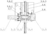
进一步的,所述非均匀校正挡片机构包括:安装在壳体底板上的底座、垂直安装在底座上的第一安装架和第二安装架、安装在第一安装架上端左侧的驱动电机、安装在第二安装架上端右侧的电位计、两端分别通过轴承安装在第一安装架和第二安装架上端左侧的旋转轴、套装在旋转轴中间位置的把轮,所述把轮位于第一安装架和第二安装架之间,所述驱动电机输出轴和电位计测量端分别与旋转轴两端相连;所述把轮圆周方向上设有多个均匀分布的安装孔,其中一个安装孔作为通光孔,其他安装孔中均安装有遮光片;校正时,启动驱动电机驱动把轮旋转使不同遮光片对准中波红外相机,校正完成后,启动驱动电机驱动把轮旋转使空白的安装孔对准中波红外相机。Further, the non-uniform correction shutter mechanism includes: a base installed on the bottom plate of the housing, a first installation frame and a second installation frame vertically installed on the base, and a drive motor installed on the left side of the upper end of the
进一步的,所述液冷压盖与连接框架连接处安装密封条进行静密封;所述第一透射液冷镜座与镜架连接处安装密封圈进行静密封;所述第二透射液冷镜座与镜架连接处安装密封圈进行静密封。Further, a sealing strip is installed at the connection between the liquid cooling gland and the connection frame for static sealing; a sealing ring is installed at the connection between the first transmission liquid cooling mirror base and the mirror frame for static sealing; the second transmission liquid cooling mirror A sealing ring is installed at the connection between the seat and the mirror frame for static sealing.
本发明的有益效果是:The beneficial effects of the present invention are:
1、通过透射式光学元件液冷机构的设计,可有效降低内部透射式光学元件温度,使光学镜片处于低温恒温状态,保持光学镜片温度恒定,有效地抑制环境温度变化对中波红外相机镜头成像质量的影响,提升中波红外相机镜头在复杂气象条件下的工作性能以及环境适应能力,提高成像质量。1. Through the design of the liquid cooling mechanism of the transmissive optical element, the temperature of the internal transmissive optical element can be effectively reduced, so that the optical lens is in a low temperature and constant temperature state, keeping the temperature of the optical lens constant, and effectively suppressing the change of the ambient temperature to image the lens of the mid-wave infrared camera Influenced by the quality, the working performance and environmental adaptability of the mid-wave infrared camera lens under complex meteorological conditions are improved, and the imaging quality is improved.
2、通过液冷壳体机构的设计,实现对液冷壳体以及中波红外相机的整体全液冷控温功能,可有效抑制环境温度变化对内部中波红外相机性能的影响,保证非均匀校正挡片机构温度均匀,从而抑制液冷壳体、中波红外相机镜头受热不均匀产生的变形以及非均匀校正挡片机构温度不均匀化的问题。2. Through the design of the liquid-cooled shell mechanism, the overall liquid-cooled temperature control function for the liquid-cooled shell and the mid-wave infrared camera can be realized, which can effectively suppress the impact of ambient temperature changes on the performance of the internal mid-wave infrared camera and ensure non-uniformity The temperature of the correction baffle mechanism is uniform, thereby suppressing the deformation caused by uneven heating of the liquid-cooled housing and the mid-wave infrared camera lens, and the problem of uneven temperature of the non-uniform correction baffle mechanism.
3、通过液冷壳体机构的设计,可使内部非均匀校正挡片机构不再受外部环境温度变化的影响,提高了非均匀校正挡片机构抵抗环境温度变化的能力,从而提高非均匀校正挡片机构对全液冷中波红外光学成像装置的非均匀校正效果,实现对远距离目标的清晰成像。3. Through the design of the liquid-cooled shell mechanism, the internal non-uniform correction flap mechanism can no longer be affected by the change of external ambient temperature, which improves the ability of the non-uniform correction flap mechanism to resist changes in ambient temperature, thereby improving the non-uniform correction The non-uniform correction effect of the baffle mechanism on the fully liquid-cooled mid-wave infrared optical imaging device realizes clear imaging of long-distance targets.
4、本发明实现了全液冷中波红外光学成像装置的全液冷设计,能够保持装置腔内温度恒定,使装置不再受环境温度变化的影响,提高了全液冷中波红外光学成像装置对多云、高温及强降雨等复杂气象条件的工作性能和环境适应能力;与现有技术相比,本发明的图像亮暗不均匀度降低4倍以上,提升了复杂气象条件下全液冷中波红外光学成像装置连续工作24小时的成像质量。4. The present invention realizes the full-liquid cooling design of the full-liquid-cooled mid-wave infrared optical imaging device, which can keep the temperature in the device cavity constant, so that the device is no longer affected by changes in ambient temperature, and improves the full-liquid-cooled mid-wave infrared optical imaging. The working performance and environmental adaptability of the device to complex meteorological conditions such as cloudy, high temperature, and heavy rainfall; compared with the prior art, the unevenness of image brightness and darkness in the present invention is reduced by more than 4 times, and the full liquid cooling under complex meteorological conditions is improved. The imaging quality of the mid-wave infrared optical imaging device works continuously for 24 hours.
5、本发明结构简单,易于实现。5. The present invention has a simple structure and is easy to realize.
附图说明Description of drawings
图1为本发明的一种全液冷中波红外光学成像装置的立体结构示意图。FIG. 1 is a schematic diagram of a three-dimensional structure of a fully liquid-cooled mid-wave infrared optical imaging device of the present invention.
图2为本发明的一种全液冷中波红外光学成像装置的内部结构示意图。FIG. 2 is a schematic diagram of the internal structure of a fully liquid-cooled mid-wave infrared optical imaging device of the present invention.
图3为液冷壳体机构的立体结构示意图。FIG. 3 is a schematic perspective view of a liquid-cooled shell mechanism.
图4为液冷板机构的结构示意图。FIG. 4 is a schematic structural diagram of a liquid-cooled plate mechanism.
图5为液冷底板的结构示意图。Fig. 5 is a schematic diagram of the structure of the liquid-cooled bottom plate.
图6为透射式光学元件液冷机构的立体结构示意图。FIG. 6 is a schematic diagram of a three-dimensional structure of a liquid cooling mechanism for a transmissive optical element.
图7为透射式光学元件液冷机构的剖面图。Fig. 7 is a cross-sectional view of a liquid cooling mechanism for a transmissive optical element.
图8为第一透射液冷镜座的结构示意图。Fig. 8 is a schematic structural view of the first transmission liquid cooling mirror mount.
图9为第二透射液冷镜座的结构示意图。Fig. 9 is a schematic structural view of the second transmission liquid cooled mirror mount.
图10为非均匀校正挡片机构的立体结构示意图。FIG. 10 is a schematic perspective view of the three-dimensional structure of the non-uniform correction shutter mechanism.
图11为非均匀校正挡片机构的剖面图。Fig. 11 is a cross-sectional view of the non-uniform correction shutter mechanism.
图12为本发明的一种全液冷中波红外光学成像装置的光学图像校正效果图。图中,A-E表示图像中的不同位置。FIG. 12 is an optical image correction effect diagram of an all-liquid-cooled mid-wave infrared optical imaging device of the present invention. In the figure, A-E represent different positions in the image.
图中,1、液冷壳体机构,1.1、液冷板机构,1.2、壳体面板,1.3、壳体底板,1.1.1、第一进液弯头,1.1.2、第一出液弯头,1.1.3、液冷压盖,1.1.4、液冷底板,1.1.5、第一液冷槽,1.1.6、连接框架,1.1.7、散热片;In the figure, 1. Liquid-cooled shell mechanism, 1.1, liquid-cooled plate mechanism, 1.2, shell panel, 1.3, shell bottom plate, 1.1.1, first liquid inlet elbow, 1.1.2, first liquid outlet elbow Head, 1.1.3, liquid cooling gland, 1.1.4, liquid cooling bottom plate, 1.1.5, first liquid cooling tank, 1.1.6, connecting frame, 1.1.7, heat sink;
2、中波红外相机;2. Mid-wave infrared camera;
3、非均匀校正挡片机构,3.1、驱动电机,3.2、旋转轴,3.3、把轮,3.4、遮光片,3.5、电位计,3.6、支架,3.7、第一轴承,3.8、第二轴承;3. Non-uniform correction shutter mechanism, 3.1, drive motor, 3.2, rotating shaft, 3.3, handle wheel, 3.4, light-shielding film, 3.5, potentiometer, 3.6, bracket, 3.7, first bearing, 3.8, second bearing;
4、透射式光学元件液冷机构,4.1、第一透射液冷镜座,4.2、第一透射进液弯头,4.3、第一透射出液弯头,4.4、镜架,4.5、第二透射出液弯头,4.6、第二透射进液弯头,4.7、第二透射液冷镜座;4. Liquid cooling mechanism for transmissive optical components, 4.1, first transmission liquid cooling mirror holder, 4.2, first transmission liquid inlet elbow, 4.3, first transmission liquid outlet elbow, 4.4, mirror frame, 4.5, second transmission Outlet elbow, 4.6, the second transmission liquid inlet elbow, 4.7, the second transmission liquid cold mirror seat;
5、液冷管组件,5.1、内腔进液弯头,5.2、内腔出液弯头,5.3、第一液冷管,5.4、第二液冷管,5.5、第三液冷管。5. Liquid cooling tube assembly, 5.1, Inner cavity liquid inlet elbow, 5.2, Inner cavity liquid outlet elbow, 5.3, First liquid cooling tube, 5.4, Second liquid cooling tube, 5.5, Third liquid cooling tube.
具体实施方式Detailed ways
以下结合附图对本发明做进一步详细说明。The present invention will be described in further detail below in conjunction with the accompanying drawings.
如图1和图2所示,本发明的一种全液冷中波红外光学成像装置,主要包括:液冷壳体机构1、中波红外相机2、非均匀校正挡片机构3、透射式光学元件液冷机构4和液冷管组件5。其中,中波红外相机2采用现有技术。中波红外相机2、非均匀校正挡片机构3、透射式光学元件液冷机构4和液冷管组件5均安装在液冷壳体机构1内部,中波红外相机2位于液冷壳体机构1内部左侧,透射式光学元件液冷机构4位于液冷壳体机构1内部右侧,非均匀校正挡片机构3位于中波红外相机2和透射式光学元件液冷机构4之间;液冷壳体机构1和透射式光学元件液冷机构4之间通过液冷管组件5相连,使透射式光学元件液冷机构4与液冷壳体机构1相连通,实现全液冷设计。As shown in Figures 1 and 2, a fully liquid-cooled mid-wave infrared optical imaging device of the present invention mainly includes: a liquid-cooled
如图3所示,液冷壳体机构1主要包括:液冷板机构1.1、壳体面板1.2、壳体底板1.3和安装孔1.4。壳体面板1.2的数量为两个,其中一个壳体面板1.2上设置有安装孔1.4;两个壳体面板1.2分别安装在壳体底板1.3左右两端;液冷板机构1.1的数量为三个,这三个液冷板机构1.1的结构组成均相同;其中第一个液冷板机构1.1安装在两个壳体面板1.2上端;第二个液冷板机构1.1安装在两个壳体面板1.2前端,第二个液冷板机构1.1下端安装在壳体底板1.3前端;第三个液冷板机构1.1安装在两个壳体面板1.2后端,第三个液冷板机构1.1下端安装在壳体底板1.3后端;中波红外相机2、非均匀校正挡片机构3、透射式光学元件液冷机构4均安装在壳体底板1.3上。As shown in FIG. 3 , the liquid-cooled
如图4和图5所示,每个液冷板机构1.1均包括:第一进液弯头1.1.1、第一出液弯头1.1.2、液冷压盖1.1.3、液冷底板1.1.4、第一液冷槽1.1.5、连接框架1.1.6和散热片1.1.7;连接框架1.1.6设置在液冷底板1.1.4外表面,第一液冷槽1.1.5设置在液冷底板1.1.4外表面,并且第一液冷槽1.1.5位于连接框架1.1.6内部;液冷压盖1.1.3安装在连接框架1.1.6上,将第一液冷槽1.1.5封装于液冷压盖1.1.3内部,同时,液冷压盖1.1.3与连接框架1.1.6的连接处加装密封条进行静密封,防止液体泄露;液冷压盖1.1.3上设置有散热片1.1.7,以增加散热面积;第一进液弯头1.1.1和第一出液弯头1.1.2均设置在液冷底板1.1.4上表面边缘;第一进液弯头1.1.1和第一出液弯头1.1.2分别与第一液冷槽1.1.5两端相连。通过在液冷板机构1.1内循环足够量的冷却液可实现全液冷中波红外光学成像装置腔内温度恒定设计。As shown in Figure 4 and Figure 5, each liquid-cooled plate mechanism 1.1 includes: the first liquid inlet elbow 1.1.1, the first liquid outlet elbow 1.1.2, the liquid-cooled gland 1.1.3, and the liquid-cooled bottom plate 1.1.4, the first liquid cooling tank 1.1.5, the connecting frame 1.1.6 and the heat sink 1.1.7; the connecting frame 1.1.6 is set on the outer surface of the liquid cooling bottom plate 1.1.4, and the first liquid cooling tank 1.1.5 is set On the outer surface of the liquid cooling bottom plate 1.1.4, and the first liquid cooling tank 1.1.5 is located inside the connecting frame 1.1.6; the liquid cooling gland 1.1.3 is installed on the connecting frame 1.1.6, and the first liquid cooling tank 1.1 .5 encapsulated inside the liquid-cooled gland 1.1.3, and at the same time, a sealing strip is installed at the connection between the liquid-cooled gland 1.1.3 and the connecting frame 1.1.6 for static sealing to prevent liquid leakage; the liquid-cooled gland 1.1.3 A heat sink 1.1.7 is arranged on the top to increase the heat dissipation area; the first liquid inlet elbow 1.1.1 and the first liquid outlet elbow 1.1.2 are both arranged on the edge of the upper surface of the liquid cooling bottom plate 1.1.4; the first liquid inlet The elbow 1.1.1 and the first liquid outlet elbow 1.1.2 are respectively connected to both ends of the first liquid cooling tank 1.1.5. By circulating a sufficient amount of cooling liquid in the liquid-cooled plate mechanism 1.1, the design of constant temperature in the cavity of the fully liquid-cooled mid-wave infrared optical imaging device can be realized.
三个液冷板机构1.1中的第一液冷槽1.1.5通过串联方式相连,使冷却液循环流动,实现液冷壳体机构1的循环液冷功能。其中,第一个液冷板机构1.1中的第一液冷槽1.1.5、第二个液冷板机构1.1中的第一液冷槽1.1.5和第三个液冷板机构1.1中的第一液冷槽1.1.5通过各自的第一进液弯头1.1.1和第一出液弯头1.1.2以及液冷管串联在一起。具体的,第一个第一液冷槽1.1.5的第一出液弯头1.1.2与第二个第一液冷槽1.1.5的第一进液弯头1.1.1通过液冷管相连,第二个第一液冷槽1.1.5的第一出液弯头1.1.2与第三个第一液冷槽1.1.5的第一进液弯头1.1.1通过液冷管相连。The first liquid cooling tanks 1.1.5 in the three liquid cooling plate mechanisms 1.1 are connected in series to make the cooling liquid circulate and realize the circulating liquid cooling function of the liquid
如图2所示,液冷管组件5主要包括:内腔进液弯头5.1、内腔出液弯头5.2、第一液冷管5.3、第二液冷管5.4和第三液冷管5.5。其中,内腔进液弯头5.1、内腔出液弯头5.2均安装在三个液冷板机构1.1中第三个液冷板机构1.1内壁上,内腔进液弯头5.1、内腔出液弯头5.2通过第一液冷管5.3、第二液冷管5.4和第三液冷管5.5与透射式光学元件液冷机构4相连。As shown in Figure 2, the liquid
如图6至图9所示,透射式光学元件液冷机构4主要包括:第一透射液冷镜座4.1、第一透射进液弯头4.2、第一透射出液弯头4.3、镜架4.4、第二透射出液弯头4.5、第二透射进液弯头4.6和第二透射液冷镜座4.7;镜架4.4安装在壳体底板1.3上;第一透射液冷镜座4.1和第二透射液冷镜座4.7分别安装在镜架4.4左右两端,第一透射进液弯头4.2和第一透射出液弯头4.3对称安装在镜架4.4左端上表面,第二透射出液弯头4.5和第二透射进液弯头4.6对称安装在镜架4.4右端上表面。第一透射液冷镜座4.1内部中空,第一透射液冷镜座4.1内部设置有透射式光学元件安装孔一4.1.2,中波红外相机2镜头中的透射式光学元件镜组一2.1安装在第一冷却镜座4.1内部的透射式光学元件安装孔一4.1.2中;第一透射液冷镜座4.1右端外表面设置有第二液冷槽4.1.1,第一透射进液弯头4.2和第一透射出液弯头4.3分别与第二液冷槽4.1.1两端相连;第二透射液冷镜座4.7内部中空,第二透射液冷镜座4.7内部设置有透射式光学元件安装孔二4.7.2,中波红外相机2镜头中的透射式光学元件镜组二2.2安装在第二透射液冷镜座4.7内部的透射式光学元件安装孔二4.7.2中,并且透射式光学元件镜组二2.2中最外侧光学镜片位于安装孔1.4中;第二透射液冷镜座4.7外表面设置有第三液冷槽4.7.1,第二透射出液弯头4.5和第二透射进液弯头4.6分别与第三液冷槽4.7.1两端相连;镜架4.4内部中空,镜架4.4左端内部设置有第一透射液冷镜座安装孔,第一透射液冷镜座4.1右端插入镜架4.4的第一透射液冷镜座安装孔中并用螺钉压紧,第一透射液冷镜座4.1与镜架4.4的连接处加装O型密封圈,可实现静密封,防止液体泄露;镜架4.4右端内部设置有第二透射液冷镜座安装孔,第二透射液冷镜座4.7插入镜架4.4的第二透射液冷镜座安装孔中并用螺钉压紧,第二透射液冷镜座4.7与镜架4.4的连接处加装O型密封圈,可实现静密封,防止液体泄露。As shown in Fig. 6 to Fig. 9, the transmissive optical element
第三个第一液冷槽1.1.5的第一出液弯头1.1.2与内腔进液弯头5.1通过液冷管相连,内腔进液弯头5.1与第一透射进液弯头4.2通过第一液冷管5.3相连,第一透射出液弯头4.3与第二透射进液弯头4.6通过第二液冷管5.4相连,第二透射出液弯头4.5与内腔出液弯头5.2通过第三液冷管5.5相连,第一个第一液冷槽1.1.5的第一进液弯头1.1.1与内腔出液弯头5.2通过液冷管相连。The first liquid outlet elbow 1.1.2 of the third first liquid cooling tank 1.1.5 is connected to the inner cavity liquid inlet elbow 5.1 through a liquid cooling tube, and the inner cavity liquid inlet elbow 5.1 is connected to the first transmission liquid inlet elbow 4.2 is connected through the first liquid cooling pipe 5.3, the first transmission liquid outlet elbow 4.3 is connected with the second transmission liquid inlet elbow 4.6 through the second liquid cooling pipe 5.4, the second transmission liquid outlet elbow 4.5 is connected with the inner cavity liquid outlet elbow The head 5.2 is connected through the third liquid cooling pipe 5.5, and the first liquid inlet elbow 1.1.1 of the first first liquid cooling tank 1.1.5 is connected with the cavity outlet elbow 5.2 through the liquid cooling pipe.
冷却液循环过程:Coolant circulation process:
冷却液通过第一个第一液冷槽1.1.5的第一进液弯头1.1.1一次性注入,然后依次经过第一个第一液冷槽1.1.5、第一个第一液冷槽1.1.5的第一出液弯头1.1.2、第二个第一液冷槽1.1.5的第一进液弯头1.1.1、第二个第一液冷槽1.1.5、第二个第一液冷槽1.1.5的第一出液弯头1.1.2、第三个第一液冷槽1.1.5的第一进液弯头1.1.1、第三个第一液冷槽1.1.5、第三个第一液冷槽1.1.5的第一出液弯头1.1.2循环后进入内腔进液弯头5.1,再依次通过第一液冷管5.3、第一透射进液弯头4.2、第二液冷槽4.1.1、第一透射出液弯头4.3、第二液冷管5.4、第二透射进液弯头4.6、第三液冷槽4.7.1、第二透射出液弯头4.5、第三液冷管5.5、内腔出液弯头5.2循环后进入第一个第一液冷槽1.1.5的第一进液弯头1.1.1,由此完成一个循环过程。通过冷却液的循环流动,实现透射式光学元件液冷机构4的整体控温功能,冷却液的流量可根据控温要求和光学结构进行设计。The coolant is injected through the first liquid inlet elbow 1.1.1 of the first first liquid cooling tank 1.1.5 at one time, and then passes through the first first liquid cooling tank 1.1.5, the first first liquid cooling The first liquid outlet elbow 1.1.2 of tank 1.1.5, the first liquid inlet elbow 1.1.1 of the second first liquid cooling tank 1.1.5, the second first liquid cooling tank 1.1.5, the second The first outlet elbow 1.1.2 of the second first liquid cooling tank 1.1.5, the first liquid inlet elbow 1.1.1 of the third first liquid cooling tank 1.1.5, the third first liquid cooling Tank 1.1.5, the first liquid outlet elbow 1.1.2 of the third first liquid cooling tank 1.1.5 circulates and enters the inner cavity liquid inlet elbow 5.1, and then passes through the first liquid cooling tube 5.3, the first transmission tube Liquid inlet elbow 4.2, second liquid cooling tank 4.1.1, first transmission liquid outlet elbow 4.3, second liquid cooling pipe 5.4, second transmission liquid inlet elbow 4.6, third liquid cooling tank 4.7.1, The second transmission liquid outlet elbow 4.5, the third liquid cooling pipe 5.5, and the inner chamber liquid outlet elbow 5.2 circulate and enter the first liquid inlet elbow 1.1.1 of the first first liquid cooling tank 1.1.5, thus completing a cyclic process. The overall temperature control function of the transmissive optical element
如图10和图11所示,非均匀校正挡片机构3采用圆周式切换设计,主要包括:驱动电机3.1、旋转轴3.2、把轮3.3、遮光片3.4、电位计3.5、支架3.6、第一轴承3.7和第二轴承3.8;支架3.6安装在壳体底板1.3上;支架3.6主要包括:底座3.6.1、第一安装架3.6.2和第二安装架3.6.3,底座3.6.1安装在壳体底板1.3上,第一安装架3.6.2和第二安装架3.6.3均垂直安装在底座3.6.1上;驱动电机3.1安装在第一安装架3.6.2上端左侧;电位计3.5安装在第二安装架3.6.3上端右侧;旋转轴3.2通过轴承安装在支架3.6上,即旋转轴3.2一端通过第一轴承3.7安装在第一安装架3.6.2上端左侧,第一轴承3.7外环固定在第一安装架3.6.2内孔中,第一轴承3.7内环固定在旋转轴3.2上;旋转轴3.2另一端通过第二轴承3.8安装在第二安装架3.6.3上端左侧,第二轴承3.8外环固定在第二安装架3.6.3内孔中,第二轴承3.8内环固定在旋转轴3.2上;驱动电机3.1输出轴与旋转轴3.2一端相连,电位计3.5测量端与旋转轴3.2另一端相连;把轮3.3中心孔套装在旋转轴3.2中间位置,把轮3.3位于第一安装架3.6.2和第二安装架3.6.3之间,把轮3.3的四分之三露出第一安装架3.6.2和第二安装架3.6.3,把轮3.3剩余四分之一被第一安装架3.6.2和第二安装架3.6.3遮挡。沿着把轮3.3圆周方向上设置有多个均匀分布的安装孔,在本实施方式中,设置有6个安装孔,其中5个安装孔中均可安装遮光片3.4,另外1个安装孔中不安装任何部件作为通光孔;校准时可根据实际工况旋转把轮3.3,使用遮光片3.4对准中波红外相机2的主光路实现遮挡,即遮光片3.4两面分别对准中波红外相机2的光电探测器探测窗口和中波红外相机2镜头,进行非均匀校正;校准完成后,驱动电机3.1带动旋转轴3.2旋转把轮3.3,将未安装任何部件的安装孔即通光孔对准中波红外相机2的主光路实现通光;启动驱动电机3.1带动旋转轴3.2转动,同时带动把轮3.3、电位计3.5一起转动,电位计3.5用于测量把轮3.3旋转角度,通过闭环控制可实现把轮3.3的精确转动。As shown in Figure 10 and Figure 11, the non-uniform correction shutter mechanism 3 adopts a circular switching design, mainly including: a driving motor 3.1, a rotating shaft 3.2, a handle wheel 3.3, a shading sheet 3.4, a potentiometer 3.5, a bracket 3.6, a first Bearing 3.7 and second bearing 3.8; Bracket 3.6 is installed on the housing bottom plate 1.3; Bracket 3.6 mainly includes: base 3.6.1, first mounting frame 3.6.2 and second mounting frame 3.6.3, base 3.6.1 is installed on On the shell bottom plate 1.3, the first mounting frame 3.6.2 and the second mounting frame 3.6.3 are installed vertically on the base 3.6.1; the driving motor 3.1 is installed on the left side of the upper end of the first mounting frame 3.6.2; the potentiometer 3.5 Installed on the right side of the upper end of the second mounting frame 3.6.3; the rotating shaft 3.2 is installed on the support 3.6 through the bearing, that is, one end of the rotating shaft 3.2 is installed on the left side of the upper end of the first mounting frame 3.6.2 through the first bearing 3.7, and the first bearing 3.7 The outer ring is fixed in the inner hole of the first installation frame 3.6.2, and the first bearing 3.7 The inner ring is fixed on the rotating shaft 3.2; the other end of the rotating shaft 3.2 is installed on the upper left end of the second mounting frame 3.6.3 through the second bearing 3.8 side, the outer ring of the second bearing 3.8 is fixed in the inner hole of the second mounting bracket 3.6.3, and the inner ring of the second bearing 3.8 is fixed on the rotating shaft 3.2; the output shaft of the driving motor 3.1 is connected with one end of the rotating shaft 3.2, and the potentiometer 3.5 measures The end is connected with the other end of the rotating shaft 3.2; the center hole of the wheel 3.3 is set in the middle position of the rotating shaft 3.2, the wheel 3.3 is located between the first mounting frame 3.6.2 and the second mounting frame 3.6.3, and the quarter of the wheel 3.3 The third exposes the first mounting frame 3.6.2 and the second mounting frame 3.6.3, and the remaining quarter of the handle wheel 3.3 is covered by the first mounting frame 3.6.2 and the second mounting frame 3.6.3. A plurality of evenly distributed mounting holes are provided along the circumferential direction of the handle wheel 3.3. In this embodiment, 6 mounting holes are provided, of which 5 mounting holes can be equipped with a light shielding sheet 3.4, and the other 1 mounting hole No component is installed as a light hole; during calibration, the handle wheel 3.3 can be rotated according to the actual working conditions, and the light-shielding sheet 3.4 is aligned with the main optical path of the mid-wave
为了验证本发明的一种全液冷中波红外光学成像装置的有效性,通过以下试验验证了本发明的校正效果,所得校正数据如表1所示,校正结果如图12所示,利用本发明的一种全液冷中波红外光学成像装置校正后,图像亮暗不均匀度为14.4%;与现有技术进行对比可知,本发明的图像亮暗不均匀度降低4倍以上,提升了复杂气象条件下全液冷中波红外光学成像装置连续工作24小时的成像质量,大大提升了全液冷中波红外光学成像装置对多云、高温及强降雨等复杂气象条件的环境适应能力,提高了全液冷中波红外光学成像装置的成像质量和工作性能。In order to verify the effectiveness of a fully liquid-cooled mid-wave infrared optical imaging device of the present invention, the correction effect of the present invention was verified through the following experiments. The obtained correction data are shown in Table 1, and the correction results are shown in Figure 12. Using this After correction of a fully liquid-cooled mid-wave infrared optical imaging device invented by the invention, the unevenness of image brightness and darkness is 14.4%. Compared with the prior art, it can be seen that the unevenness of image brightness and darkness in the present invention is reduced by more than 4 times, which improves the The imaging quality of the full liquid-cooled mid-wave infrared optical imaging device working continuously for 24 hours under complex weather conditions has greatly improved the environmental adaptability of the full liquid-cooled mid-wave infrared optical imaging device to complex weather conditions such as cloudy, high temperature and heavy rainfall, and improved The imaging quality and working performance of the fully liquid-cooled mid-wave infrared optical imaging device were tested.
表1Table 1

在本发明的描述中,需要理解的是,术语“中心”、“纵向”、“横向”、“前”、“后”、“左”、“右”、“竖直”、“水平”、“顶”、“底”、“内”、“外”等指示的方位或位置关系为基于附图所示的方位或位置关系,仅是为便于描述本发明和简化描述,而不是指示或暗指所指的装置或元件必须具有特定的方位、为特定的方位构造和操作,因而不能理解为对本发明保护内容的限制。In describing the present invention, it is to be understood that the terms "central", "longitudinal", "transverse", "front", "rear", "left", "right", "vertical", "horizontal", The orientations or positional relationships indicated by "top", "bottom", "inner", "outer", etc. are based on the orientations or positional relationships shown in the drawings, and are only for the convenience of describing the present invention and simplifying the description, rather than indicating or implying It means that the device or element referred to must have a specific orientation, be constructed and operated for a specific orientation, and thus cannot be construed as limiting the protection content of the present invention.
最后应说明的是:以上实施例仅用以说明本发明的技术方案,而非对其限制;尽管参照前述实施例对本发明进行了详细的说明,本领域的普通技术人员应当理解:其依然可以对前述各实施例所记载的技术方案进行修改,或者对其中部分技术特征进行等同替换,但这些修改或者替换,并不使相应技术方案的本质脱离本发明各实施例技术方案的精神和范围。Finally, it should be noted that: the above embodiments are only used to illustrate the technical solutions of the present invention, rather than to limit them; although the present invention has been described in detail with reference to the foregoing embodiments, those of ordinary skill in the art should understand that: it can still be Modifications are made to the technical solutions described in the foregoing embodiments, or equivalent replacements are made to some of the technical features, but these modifications or replacements do not make the essence of the corresponding technical solutions deviate from the spirit and scope of the technical solutions of the various embodiments of the present invention.
Claims (3)
Priority Applications (1)
| Application Number | Priority Date | Filing Date | Title |
|---|---|---|---|
| CN202210828604.XA CN114910175B (en) | 2022-07-15 | 2022-07-15 | A fully liquid-cooled mid-wave infrared optical imaging device |
Applications Claiming Priority (1)
| Application Number | Priority Date | Filing Date | Title |
|---|---|---|---|
| CN202210828604.XA CN114910175B (en) | 2022-07-15 | 2022-07-15 | A fully liquid-cooled mid-wave infrared optical imaging device |
Publications (2)
| Publication Number | Publication Date |
|---|---|
| CN114910175A CN114910175A (en) | 2022-08-16 |
| CN114910175B true CN114910175B (en) | 2022-11-01 |
Family
ID=82772630
Family Applications (1)
| Application Number | Title | Priority Date | Filing Date |
|---|---|---|---|
| CN202210828604.XA Active CN114910175B (en) | 2022-07-15 | 2022-07-15 | A fully liquid-cooled mid-wave infrared optical imaging device |
Country Status (1)
| Country | Link |
|---|---|
| CN (1) | CN114910175B (en) |
Citations (1)
| Publication number | Priority date | Publication date | Assignee | Title |
|---|---|---|---|---|
| CN111175965A (en) * | 2020-02-28 | 2020-05-19 | 中国科学院上海技术物理研究所 | An infrared imaging system and imaging method based on filter wheel rotation imaging |
Family Cites Families (9)
| Publication number | Priority date | Publication date | Assignee | Title |
|---|---|---|---|---|
| CN101470026A (en) * | 2007-12-24 | 2009-07-01 | 南京理工大学 | Ununiformity emendation real-time calibration apparatus for staring type thermal imaging system |
| CN104897284A (en) * | 2014-03-04 | 2015-09-09 | 中石化洛阳工程有限公司 | Temperature measurement device for hearth workpiece surface and temperature measurement method |
| CN108420447B (en) * | 2018-03-07 | 2024-05-17 | 湖北锐世数字医学影像科技有限公司 | Cooling assembly of imaging device |
| CN209326792U (en) * | 2019-01-18 | 2019-08-30 | 杭州海康威视数字技术股份有限公司 | Thermal infrared imager |
| CN110672213A (en) * | 2019-09-23 | 2020-01-10 | 南京理工大学 | Uncooled infrared system with built-in correction block and correction method thereof |
| CN211063667U (en) * | 2019-12-18 | 2020-07-21 | 张家港市港区电视设备有限公司 | Explosion-proof infrared camera with radiating effect |
| CN111770258B (en) * | 2020-07-23 | 2021-12-28 | 深圳市狮安联讯科技有限公司 | Rotatory heat dissipation formula security protection surveillance camera head |
| CN113074819B (en) * | 2021-04-02 | 2022-03-29 | 北京理工大学 | A high-precision infrared temperature measurement system and method |
| CN114441050B (en) * | 2022-01-26 | 2024-10-01 | 西安应用光学研究所 | Thermal imager real-time non-uniformity correction method based on rotary baffle |
-
2022
- 2022-07-15 CN CN202210828604.XA patent/CN114910175B/en active Active
Patent Citations (1)
| Publication number | Priority date | Publication date | Assignee | Title |
|---|---|---|---|---|
| CN111175965A (en) * | 2020-02-28 | 2020-05-19 | 中国科学院上海技术物理研究所 | An infrared imaging system and imaging method based on filter wheel rotation imaging |
Also Published As
| Publication number | Publication date |
|---|---|
| CN114910175A (en) | 2022-08-16 |
Similar Documents
| Publication | Publication Date | Title |
|---|---|---|
| US20090129021A1 (en) | Gas station television | |
| CN201672917U (en) | Underwater optical pan-tilt scanning image observation device | |
| CN114910175B (en) | A fully liquid-cooled mid-wave infrared optical imaging device | |
| CN101587260B (en) | Liquid crystal display device | |
| CN109471515A (en) | a cooling case | |
| CN210986255U (en) | Camera for intelligent monitoring with heat dissipation function | |
| CN209311835U (en) | LCD display | |
| CN217443720U (en) | Bare engine with internal circulating heat dissipation mechanism | |
| CN216817127U (en) | LED backlight source mounting structure | |
| CN211478843U (en) | Projector with a light source | |
| CN119668015A (en) | Cooling device for liquid soaking and heat dissipation of projector liquid crystal screen | |
| CN222463401U (en) | A circulator with good heat dissipation effect | |
| CN208126059U (en) | A kind of optics module equipment of LCD | |
| CN213814251U (en) | Projector | |
| CN216595867U (en) | Internal cooling structure of totally-enclosed projector | |
| JP2003015130A (en) | Liquid crystal display | |
| CN114895512B (en) | Industrial camera conformal active and passive mixed cooling heat dissipation rear cover | |
| CN219435477U (en) | Dustproof display screen | |
| CN219842621U (en) | Projector with double heat dissipation channels | |
| CN222351403U (en) | Cooling device based on speed change gear box | |
| CN211319641U (en) | Advertisement projection equipment | |
| CN220232218U (en) | Multi-angle adjusting device for light path of projector | |
| CN219068721U (en) | Heat radiation structure of image sensor | |
| CN218113032U (en) | Split heat sink for star sensor hood | |
| CN216595869U (en) | Radiating tube of totally-enclosed projector |
Legal Events
| Date | Code | Title | Description |
|---|---|---|---|
| PB01 | Publication | ||
| PB01 | Publication | ||
| SE01 | Entry into force of request for substantive examination | ||
| SE01 | Entry into force of request for substantive examination | ||
| GR01 | Patent grant | ||
| GR01 | Patent grant |