Disclosure of Invention
In view of the above problems in the prior art, an object of the present disclosure is to provide a system and a method for testing damage to a submarine pipeline caused by a trawl board accident, so as to solve the problem in the prior art that damage to the pipeline after being hit, trailed and hooked by the trawl board in fishery is not easy to determine.
In order to solve the technical problems, the specific technical scheme is as follows:
in one aspect, a system for testing damage to a subsea pipeline from a trawl door accident is provided herein, comprising a test tank, a pipeline model, a trawl door model, a control system, a power system, a regulation system, and a measurement system;
the pipeline model is positioned in the test tank, and the trawl board model is positioned in the test tank and connected with the power system;
the power system is arranged at the top of the test tank and connected with the control system, and the power system is used for driving the trawl board model to move relative to the pipeline model under the control of the control system;
the adjusting system is arranged on the trawl board model and/or the pipeline model, is connected with the control system and is used for adjusting the relative position between the trawl board model and the pipeline model so as to enable the trawl board model to have an accident with the pipeline model when moving relative to the pipeline model;
The measurement system is connected with the control system and used for acquiring test data when accidents happen to the trawl board model and the pipeline model and sending the test data to the control system;
the control system is used for sending a control command to the power system and sending the test data to the processing equipment.
Specifically, the power system comprises a motor, a transmission assembly, a synchronous belt guide rail and a sliding block;
the motor with control system is connected, drive assembly's one end set up in on the motor, drive assembly's the other end is provided with the hold-in range, the hold-in range sets up on the hold-in range guide rail, the hold-in range guide rail set up the test tank the top and with pipeline model non-parallel arrangement, the one end of slider with the hold-in range meets, the other end of slider with the trawl board model links to each other, the motor is in corotation or reversal under control system's control, and then the promotion the hold-in range rotates in order to drive the trawl board model is followed the hold-in range guide rail removes.
Furthermore, two opposite sides of the test tank are respectively provided with a support table, the synchronous belt guide rail is connected to the support tables in a bridging manner, and the motor is arranged on one support table;
Each support platform comprises a support plate and a support column which are connected, the height of each support column is matched with that of the test tank, and the control system is arranged on any one support plate.
Specifically, the measuring system comprises a first acceleration sensor, an impact force sensor, a second acceleration sensor, a three-dimensional force sensor, a strain gauge and a laser displacement sensor; the first acceleration sensor and the impact force sensor are both arranged on the trawl door model; the second acceleration sensor, the three-dimensional force sensor and the strain gauge are all arranged on the pipeline model; the laser displacement sensor is arranged on the inner wall of the test groove.
Further, the trawl door model comprises a trawl door main body and an impact head;
the impact force sensor is arranged between the impact head and the trawl door main body; the trawl board is characterized in that a fixing seat is arranged on the trawl board main body and is used for being connected with a connecting piece, one end, far away from the fixing seat, of the connecting piece is connected with the sliding block, and the first acceleration sensor is arranged at the fixing seat.
Further, the pipe model includes a pipe main body and a pipe installation auxiliary block;
The pipeline installation auxiliary blocks are arranged at two ends of the pipeline main body and are used for limiting the pipeline main body to roll; the second acceleration sensor, the three-dimensional force sensor and the strain gauge are all arranged on the pipeline main body.
Preferably, the pipe model further comprises a pipe bearing pillar, and the pipe main body is mounted at the bottom of the test tank through the pipe mounting auxiliary block and the pipe bearing pillar.
Specifically, the adjustment system includes a first adjustment assembly and a second adjustment assembly;
the first adjusting assembly is connected with the trawl board model and is used for adjusting the height and/or the angle of the trawl board model so as to adjust the relative position between the trawl board model and the pipeline model;
the second adjusting component is arranged on the pipeline bearing support and used for adjusting the height of the pipeline model, and further adjusting the relative position between the trawl board model and the pipeline model.
Preferably, the test tank is also provided with an observation window; the test tank is also filled with seawater and/or seabed soil.
On the other hand, the text also provides a method for testing damage of a trawl door accident to a submarine pipeline, which is applied to the test system provided by the technical scheme, and the method comprises the following steps:
Receiving test condition design data, wherein the test condition design data comprises: the relative position between the trawl board model and the pipeline model, the quality of the trawl board model, the quality of the pipeline model and the speed of the trawl board model and the pipeline model when accidents happen;
adjusting the relative position of the trawl board model and the pipeline model by using the adjusting system according to the relative position in the test condition design data;
providing an instruction for the power system by using the control system so that the power system drives the trawl board model to move relative to the pipeline model, and further an accident occurs;
and establishing a damage model of the trawl board accident on the submarine pipeline by using test data measured by the measuring system when the accident occurs and the test condition design data.
By adopting the technical scheme, the test system and the test method for damage of the trawl board accident to the submarine pipeline provided by the invention can test different types of trawl board models, different types of pipelines, different accident types between the trawl board models and the pipeline models, different relative positions between the trawl board models and the pipeline models and the like, and the test range is wide and comprehensive; each part has high integration and modularization degree, and is convenient to assemble and disassemble; and the control is realized through a control system, semi-automation or full automation is realized, the test efficiency and accuracy are improved, and an important guiding function is provided for the structural damage deformation rule of the pipeline.
In order to make the aforementioned and other objects, features and advantages of the present invention comprehensible, preferred embodiments accompanied with figures are described in detail below.
Detailed Description
The technical solutions in the embodiments of the present invention will be clearly and completely described below with reference to the drawings in the embodiments of the present invention, and it is obvious that the described embodiments are only a part of the embodiments of the present invention, and not all of the embodiments. All other embodiments, which can be derived by a person skilled in the art from the embodiments herein without making any creative effort, shall fall within the scope of protection.
It should be noted that the terms "first," "second," and the like in the description and claims herein and in the above-described drawings are used for distinguishing between similar elements and not necessarily for describing a particular sequential or chronological order. It is to be understood that the data so used is interchangeable under appropriate circumstances such that the embodiments herein described are capable of operation in sequences other than those illustrated or described herein. Furthermore, the terms "comprises," "comprising," and "having," and any variations thereof, are intended to cover a non-exclusive inclusion, such that a process, method, apparatus, article, or device that comprises a list of steps or elements is not necessarily limited to those steps or elements expressly listed, but may include other steps or elements not expressly listed or inherent to such process, method, article, or device.
The submarine pipeline plays a role of a lifeline in the whole offshore oil industry system, the length of the submarine pipeline is further increased along with the scale-up of the offshore oil industry, and the construction of part of the submarine pipeline inevitably generates relevant intersection with the traditional offshore fishery area. During fishery operation, various accidents such as collision, dragging or hooking on the submarine pipeline can occur, and accidental damage can be caused to the submarine pipeline. In order to better detect the damage of the submarine pipeline caused by impact, dragging, hooking and the like, a test system and a test method for the damage of the submarine pipeline caused by a trawl board accident are urgently needed.
As shown in fig. 1 to 12, the testing system may include:
comprises a test tank 10, a pipeline model 20, a trawl board model 30, a control system 40, a power system 50, a regulating system and a measuring system 60;
the pipeline model 20 is positioned in the test tank 10, and the trawl door model 30 is positioned in the test tank 10 and connected with the power system 50;
the power system 50 is arranged at the top of the test tank 10 and is connected with the control system, and the power system 50 is used for driving the trawl door model 30 to move relative to the pipeline model 20 under the control of the control system 40;
the adjusting system is arranged on the trawl door model 30 and/or the pipeline model 20, the adjusting system is connected with the control system 40, and the adjusting system is used for adjusting the relative position between the trawl door model 30 and the pipeline model 20 so as to cause accidents such as collision, dragging, crossing or hooking between the trawl door model 30 and the pipeline model 20 when the trawl door model moves relative to the pipeline model 20;
the measuring system 60 is connected with the control system 40, and the measuring system 60 is used for acquiring test data when the trawl board model 30 and the pipeline model 20 have accidents such as collision, dragging, crossing or hooking and the like and sending the test data to the control system 40;
The control system 40 is configured to send control commands to the power system 50 and to send the received test data to a processing device. The processing device may be part of the control system or may be separate from the control system.
It should be noted that in the embodiment of the present specification, when the relative positions (including the relative heights and the relative angles) between the trawl door model 30 and the pipe model 20 are different, the type of trawl door accident occurring between the trawl door model 30 and the pipe model 20 is different. In the embodiment of the specification, the trawl door accident (contact accident) mainly includes an impact accident, a trawl accident and a hooking accident. Further, in the case of a collision accident, the trawl door model 30 moves to a direction close to the pipe model 20 (for example, as shown in fig. 9 and 10, the position of the pipe model 20 is not changed, and the trawl door model 30 moves from the left side to the right side of the figure), and a hard collision occurs when the trawl door model contacts the pipe model 20; a trawl over incident means that the trawl door model 30 contacts the middle upper portion of the pipe model 20 and moves a distance along the surface of the pipe model (as shown in fig. 11) in the process that the trawl door model 30 moves from the left side of the figure to the right side of the figure; the hooking accident is a condition that the trawl door model 30 contacts the lower portion of the duct model 20 when moving to the right side of the drawing from the left side of the drawing, and the trawl door model 30 is restricted from moving by the duct model 20 and hooked to the duct model 20 when the trawl door model 30 continues to move to the right side (as shown in fig. 12). In an actual scene, the collision accidents are generally connected with trawl accidents or hooking accidents, and in the embodiment of the specification, the accidents are separated so as to more accurately detect the damage condition of different types of trawl board accidents on the pipeline model.
In the system for testing damage of the trawl door accident to the submarine pipeline provided by the embodiment of the present specification, the trawl door model 30 can move relative to the pipeline model 20 under the control of the control system 40, and the relative positions of the trawl door model 30 and the pipeline model 20 are adjusted by the adjusting system to simulate different types of trawl door accidents, thereby filling a technical gap that the prior art cannot simulate accidents such as collision, trawling, hooking and the like of the trawl door and the submarine pipeline, being beneficial to determining the damage condition of the pipeline model in different accident scenes, and being convenient for maintenance of the submarine pipeline.
As shown in fig. 3 and 4, the power system 50 includes a motor 51, a transmission assembly (not shown), a timing belt 52, a timing belt guide 58 and a slider 53;
one end of the transmission assembly is arranged on the motor, the other end of the transmission assembly is provided with the synchronous belt 52, the transmission assembly can be a transmission gear, and the transmission assembly is used for changing the transmission ratio output by the motor 51; the synchronous belt 52 is arranged on the synchronous belt guide rail 58, the synchronous belt guide rail 58 is arranged on the top of the test tank 10 and is arranged in a non-parallel way with the pipeline model 20, so that when the trawl door model 30 moves along the synchronous belt guide rail 58, the synchronous belt guide rail 58 is inevitably contacted with the pipeline model 20 to cause a corresponding accident; one end of the sliding block 53 is connected with the synchronous belt 52, and the other end of the sliding block 53 is connected with the trawl door model 30; the motor 51 is connected to the control system 40, and the motor 51 is configured to rotate forward or backward under the control of the control system 40 to drive the synchronous belt 52 to rotate so as to drive the trawl door model 30 to move along the synchronous belt guide rail 58, so that the trawl door model 30 and the pipeline model 20 have accidents such as collision, trawling or hooking.
In some possible embodiments, the power system 50 further includes a coupling 54 (shown in fig. 4), and the coupling 54 is used for connecting the motor 51 and the synchronous belt guide 58. Then, when assembling the power system 50, the timing belt 52, the timing belt guide 58 and the slider 53 may be assembled: sliding the sliding block 53 into the synchronous belt 52 from one end of the synchronous belt 52, and completing connection and fixation with the synchronous belt 52 through a fastener (such as a screw) reserved at the sliding block 53; the timing belt 52 is attached to a timing belt guide 58. The slider mounting aid 55 is connected through the mounting hole sites reserved on the slider 53, and the slider mounting aid 55 is used for subsequent connection with the trawl door model 30, as shown in fig. 3. After the above-described installation is completed, the slider 53 is slightly pushed to check whether it slides on the timing belt guide 58 along with the timing belt 52. The synchronous belt guide 58 is then connected to the motor 51: connecting one end of a coupler protective frame 56 with a synchronous belt guide rail 58, extending a coupler 54 from the inside of the coupler protective frame 56 and connecting the coupler 54 with the end part of the synchronous belt guide rail 58, namely sleeving the coupler protective frame 56 outside the coupler 54; connecting the other end of the coupler protective frame 56 with the motor 51, inserting bolts into the motor 51 through the mounting holes reserved on the motor mounting auxiliary block 57 to connect the motor 51 to the coupler 54, thereby completing the assembly of the power system 50, as shown in fig. 4. The rotation of the timing belt 52 and the movement of the slider 53 are subsequently driven by the rotation of the motor 51.
As shown in fig. 2 and 5, the test bath 10 is provided with a support stand at opposite sides thereof, and may be disposed at left and right sides as shown in fig. 2, for example. The synchronous belt guide rail 58 is connected across the two support tables, and the motor 51 is disposed on one of the support tables. Each support platform comprises a support plate 74 and a support column 75 which are connected, the height of the support column 75 is matched with the height of the test tank 10, and the control system 40 can be arranged on any one support plate 74.
In the present embodiment, the support bases provided on both sides of the test cell 10 may have the same arrangement or different arrangements. For example, as shown in fig. 5, the support table located on the left side of the test cell 10 is referred to as a first support table 71, and the first support table 71 is assembled by three support plates 74 and two support columns 75; the support table on the right side of test cell 10 is designated as second support table 72, and second support table 72 is assembled from two support plates 74 and two support columns 75. Of course, the number of the support plates 74 and the number of the support columns 75 included in the first support table 71 and the second support table 72 may be other numbers. All the support columns 75 are uniform in size (height and thickness), and all the support plates 74 are also uniform in size; and the support plate 74 and the support column 75 can be connected by screw threads to ensure the firmness and the bearing capacity of the integral connection.
The synchronous belt guide rail 58 is connected one end of the motor 51 and the motor 51 are arranged on the first supporting table 71, and the other end, far away from the motor 51, of the synchronous belt guide rail 58 is arranged on the second supporting table 72. Optionally, the control system 40 is disposed on a support plate 74 intermediate the first support table 71 (as shown in FIG. 2). Preferably, be provided with motor mounting groove 73 on the first supporting bench 71, motor mounting groove 73 is used for guaranteeing the steadiness that motor 51 connects, and the height drop between motor 51 and the hold-in range guide rail 58 can be got rid of to motor mounting groove 73 simultaneously, guarantees hold-in range guide rail 58 both ends are located same level, thereby guarantees trawl board model 30 is following its speed is only influenced by motor 51 output when hold-in range 52 removes, gets rid of other interference factor, improves the accuracy of simulation.
Preferably, a counterweight block may be further disposed at a lowermost supporting plate 74 of the first supporting table 71 and the second supporting table 72, so as to enhance the overall stability of the supporting tables and avoid the shaking of the motor.
In other possible embodiments, the end of the timing belt guide 58 may move on the first support table 71 and/or the end of the timing belt guide 58 may move on the second support table 72. When the two ends of the synchronous belt guide rail 58 move synchronously, the trawl door model 30 can be driven to move along the axial direction of the pipeline model 20, so that the accident position can be adjusted, multiple tests can be performed on the same pipeline model 20 at different positions, and the replacement frequency of the pipeline model 20 is reduced. When the two ends of the timing belt guide 58 are moved asynchronously, not only the position of the trawl door model 30 with respect to the pipe model in the direction along the axis thereof but also the relative angle of the trawl door model 30 with respect to the pipe model 20 can be adjusted.
As shown in fig. 8, the measurement system 60 includes a first acceleration sensor 61, an impact force sensor 62, a second acceleration sensor 63, a three-dimensional force sensor 64, a strain gauge 65, and a laser displacement sensor 66; the first acceleration sensor 61 and the impact force sensor 62 are both disposed on the trawl door model 30; the second acceleration sensor 63, the three-dimensional force sensor 64, and the strain gauge 65 are all provided on the pipe model 20; the laser displacement sensor 66 is arranged on the inner wall of the test groove (shown in figure 1). More than one strain gauge 65 may be provided, and the strain gauge 65 is provided near a position where the pipe main body 21 collides with, trails over, or hooks on the trawl door model 30. Preferably, the set height of the laser displacement sensor 66 is adapted to the height of the trawl door model 30 and/or the pipe model 20, so that the laser displacement sensor 66 can shoot images and videos when the trawl door model 30 collides, trails or hooks with the pipe model 20.
As shown in FIG. 6, the trawl door model 30 includes a trawl door body 31 and an impact head 32; the impact force sensor 62 is arranged between the impact head 32 and the trawl door main body 31; the trawl board main body 31 is provided with a fixed seat, the fixed seat is connected with a connecting piece 33, one end of the connecting piece 33, which is far away from the fixed seat, is connected with the sliding block 53, and the first acceleration sensor 61 is arranged at the fixed seat.
In some possible embodiments, a cutting opening for inserting the impact force sensor 62 can be cut out of the trawl door body 31, and the impact head 32 and the trawl door body 31 are preferably made of the same material; the impact force sensor 62 is fixedly connected with the trawl door main body 31 in an adhesive mode, and then the front end of the impact force sensor 62 is fixedly connected with the impact head 32 in an adhesive mode, so that the geometrical contact between the trawl door model and the pipeline model when the trawl door accident occurs is favorably ensured.
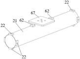
The pipe mold 20 includes a pipe main body 21 and a pipe installation auxiliary block 22; the pipe installation auxiliary blocks 22 are provided at both ends of the pipe main body 21. Since the pipe body 21 is generally cylindrical, if it is directly placed at the bottom of the test chamber 10, it may roll before, during, and after the collision, dragging, and hooking accident with the trawl door model 30, which affects the accuracy of the collision, dragging, and hooking accident simulation test. Therefore, in the embodiment of the present specification, pipe installation auxiliary blocks 22 are provided at both ends of the pipe mold 20 for restricting the rolling of the pipe main body 21. The second acceleration sensor 63 and the three-dimensional force sensor 64 are both provided on the pipe main body. Specifically, the three-dimensional force sensor 64 is smoothly disposed on the pipe main body 21 by a three-dimensional force sensor installation assisting jig 67.
It should be noted that, in the embodiment of the present specification, the pipe model 20 may be adjusted and replaced according to specific test requirements, for example, replacing the pipe main body 21 with different lengths, different diameters, and different wall thicknesses; likewise, the trawl door body 31 of the trawl door model may be adjusted and replaced according to the specific test requirements, for example, replacing trawl door bodies having different sizes and different volumes.
Preferably, more than one auxiliary pipe installation blocks 22 are arranged at both ends of the main pipe body 21, and the auxiliary pipe installation blocks 22 are uniformly distributed on the outer side surface of the cylindrical surface of the main pipe body. For example, as shown in fig. 7, two ends of the pipe model 20 are each provided with 4 pipe installation auxiliary blocks 22, and the 4 pipe installation auxiliary blocks 22 at each end are located on the same plane (the plane is parallel to a cross section perpendicular to the axial direction of the pipe model), and are uniformly distributed along the outer contour of the plane, so that the area of the pipe main body 21 for the test can be increased; the auxiliary pipeline installation blocks 22 at the two ends of the main pipeline body 21 are symmetrical, that is, the connecting line of the two auxiliary pipeline installation blocks 22 at the two ends is parallel to the axis of the main pipeline body, so that the main pipeline body 21 is stably placed in the test cell 10.
In fig. 7, two sets of auxiliary pipeline installation blocks 22 are connected to the main pipeline body 21, the two sets of auxiliary pipeline installation blocks are respectively located at two ends of the main pipeline body 21, and each set has 4 auxiliary pipeline installation blocks. Of course, in some other embodiments, the duct main body 21 may be connected with another number of the duct installation auxiliary blocks 22 to improve the assembling stability of the duct main body 21. For example, when the pipe main body 21 is long (when the capacity of the test cell 10 allows), more than two sets of the pipe installation auxiliary blocks 22 may be connected to the pipe main body 21, that is, in addition to the pipe installation auxiliary blocks 22 provided at both ends of the pipe main body 21, a set of pipe installation auxiliary blocks may be added at a middle position of the pipe main body 21.
As shown in fig. 2, the pipe mold 20 may further include a pipe carrying support 23, and the pipe main body 21 is mounted at the bottom of the test bath 10 through the pipe mounting auxiliary block 22 and the pipe carrying support 23. The number and the arrangement positions of the pipeline bearing struts 23 should correspond to the pipeline installation auxiliary blocks 22, and different scenes laid by the pipeline model 20 can be simulated through the pipeline bearing struts 23 with different heights, specifically, the method includes: rigid plane support (the pipeline model is directly and rigidly connected with the bottom of the test slot), rigid suspension span (the pipeline model is connected through a pipeline bearing support), seabed soil landfill at different depths, different proportions of seabed soil components and the like.
In some preferred embodiments, the adjustment system includes a first adjustment assembly and a second adjustment assembly.
The first adjusting component is connected to the trawl door model 30, and is used for adjusting the height and/or angle of the trawl door model 30, so as to adjust the relative position between the trawl door model 30 and the pipeline model 20. For example, the first adjusting component may include a first lifting motor, a gear, and the like, the first lifting motor is connected to the control system, and the first lifting motor is further connected to the connecting member through the gear, so that under the control of the control system, the first lifting motor works and drives the connecting member to lift and lower, thereby adjusting the relative heights of the trawl board model 30 and the pipeline model 20. The connecting member may be connected to the slider through the slider mounting auxiliary block 55, and the first adjusting member may further include a rotating motor, the rotating motor is connected to the control system, and the rotating motor rotates to change an angle between the slider mounting auxiliary block 55 and the slider 53 under the control of the control system, so as to adjust a relative angle between the trawl board model 30 and the pipeline model 20. Of course, the adjustment of the relative height and/or angle between the trawl door model 30 and the duct model 20 can be performed by manual adjustment, for example, replacing the connecting members with different lengths, manually adjusting the included angle between the sliding block mounting auxiliary block 55 and the sliding block 53, and so on.
The second adjusting component is arranged on the pipeline bearing strut 23, and is used for adjusting the height of the pipeline model 20, so as to adjust the relative position between the trawl door model 30 and the pipeline model 20. For example, the second adjusting assembly may include a second lifting motor, the second lifting motor is connected to the control system, the first lifting motor is further connected to the pipe carrying pillar 23, the pipe carrying pillar 23 may include a main pillar and a sub pillar which are telescopically connected, so that under the control of the control system, the second lifting motor works and drives the sub pillar to telescope relative to the main pillar, thereby adjusting the relative height between the trawl door model 30 and the pipe model 20. In order to realize the simulation of the seabed environment, the second lifting motor can also be a hydraulic mechanism or a pneumatic mechanism.
In some possible embodiments, the simulation of the laying scene in which the pipe main body 21 is inclined to the bottom of the test tank 10 may be implemented by adjusting the pipe bearing pillars 23 at the two ends of the pipe main body 21 to have different lifting heights (a structure coordinating with the inclination angle is provided between the pipe bearing pillars 23 and the pipe main body 21).
As shown in fig. 1 and 2, the test tank 10 is further provided with a viewing window 11 for easy viewing; the test cell 10 may also be filled with seawater and/or seabed soil. It should be noted that the seabed soil in the embodiments of the present description refers to a soil environment of the seabed, which includes soil, sand, stones, and the like; through simulation of the pipeline model in different laying scenes, research on the impact energy absorption capacity of seawater and seabed soil in case of trawl board accidents can be realized.
The control system 40 may include a PLC controller, a control switch, and a frequency converter; the PLC is connected with a motor 51 of a power system and is used for programming the motor 51 to realize the control of the relative displacement, the absolute speed and the regular motion period of a sliding block 53 on a synchronous belt; the control switch is connected with a power supply line of a motor 51 in the power system through an external power supply line interface and is used for controlling the start and stop of the servo motor; the control switch is also connected with a frequency converter, and the frequency converter is modulated to be in a forced energy state to meet the control requirement on the pulse rotating speed of the motor.
To sum up, the system for testing damage of the trawl board accident to the submarine pipeline provided by the embodiment of the present specification can test different types of trawl board models, different types of pipelines, different accident types (impact, trawling and hooking) between the trawl board models and the pipeline models, different relative positions (relative height and relative angle) between the trawl board models and the pipeline models, and different laying scenes of the pipeline models, so that the technical blank of the prior art in the field is made up, and the test range is wide and comprehensive; each part has high integration and modularization degree, and is convenient to assemble and disassemble; and control is realized through a control system, semi-automation or full automation is realized, the test efficiency is improved, meanwhile, the reduction of test errors is facilitated, the test accuracy is improved, and important guiding significance is provided for the structural damage deformation rule of the pipeline.
As shown in fig. 13, the present specification provides a method for testing damage to a submarine pipeline caused by a trawl door accident based on the above-mentioned testing system, and provides the method operation steps as described in the examples or flowcharts, but may include more or less operation steps based on conventional or non-creative labor. The order of steps recited in the embodiments is merely one manner of performing the steps in a multitude of sequences, and does not represent a unique order of performance. In the actual implementation of the system or the device product, the method according to the embodiments or shown in the drawings can be executed in sequence or in parallel. Specifically, as shown in fig. 13, the method may include:
s1310: and receiving test condition design data, wherein the test condition design data comprises the relative position between the trawl board model and the pipeline model, the quality of the trawl board model, the quality of the pipeline model and the speed of the trawl board model and the pipeline model when accidents happen.
The relative position between the trawl door model and the pipeline model comprises the relative height and the relative angle between the trawl door model and the pipeline model, and the relative height is related to the type of accidents occurring between the trawl door model and the pipeline model; the relative angle is the included angle between the two accidents, namely the trawl board model can be vertical to the pipeline model to cause the accidents, or can form a certain inclination angle with the pipeline model to cause the accidents.
S1320: and adjusting the relative position of the trawl board model and the pipeline model by using the adjusting system according to the relative position in the test condition design data.
S1330: and providing an instruction for the power system by using the control system so that the power system drives the trawl board model to move relative to the pipeline model, thereby generating an accident.
That is, the control system provides instructions to set the speed of the trawl door model and the pipe model at the time of the accident as the designed speed in the design data of the test conditions in step S1310.
S1340: and establishing a damage model of the trawl board accident on the submarine pipeline by using test data measured by the measuring system when the accident occurs and the test condition design data.
The test data can comprise shot pictures and images of the trawl board model and the pipeline model when accidents happen; traces and trace photos of the pipeline model after an accident; and the trace depth is obtained by measuring the trace, and microscopic damage information inside the pipeline material is obtained by comparing a trace photo with a pipeline model of the same model without accidents under a metallographic microscope, and the like.
Therefore, a damage model is established on the basis, damage identification can be carried out on trawl board accidents occurring with submarine pipelines during fishing boat operation, and proper repairing and maintenance measures are made according to the damage identification result, so that serious damages such as damage and leakage of the pipelines are avoided; guiding the laying of submarine pipelines, laying pipelines which are more resistant to impact, dragging and hooking damage in areas with frequent fishery activities, protecting the pipelines from submarine soil coverage and the like; the design of the submarine pipeline can be improved according to the damage model, the pipeline which is firmer and more impact-resistant is designed, and accidents such as leakage are avoided.
The embodiment of the specification provides a method for testing damage of a trawl board accident to a submarine pipeline, which fills the blank in the aspects of simulation of accidents such as impact, dragging, hooking and the like between the trawl board and the submarine pipeline, analysis of damage after the accident and the like in the prior art, can improve the simulation accuracy when the trawl board and the pipeline have faults, improve the accuracy of judging and identifying the pipeline damage, and establish a damage model to provide scientific guidance for maintenance, laying and design improvement of the pipeline.
As shown in fig. 14, the present specification further provides a device for testing damage to a submarine pipeline caused by a trawl door accident, including:
The receiving module 1410 is configured to receive test condition design data, where the test condition design data includes a relative position between the trawl board model and the pipeline model, a quality of the trawl board model, a quality of the pipeline model, and a speed of an accident occurring between the trawl board model and the pipeline model.
And an adjusting module 1420, configured to adjust the relative position of the trawl door model and the pipeline model according to the relative position in the test condition design data by using the adjusting system.
And a driving module 1430, configured to provide an instruction for the power system by using the control system, so that the power system drives the trawl door model to move relative to the pipeline model, thereby causing an accident.
The model building module 1440 is configured to build a damage model of the trawl door accident on the submarine pipeline by using the test data measured by the measurement system when the accident occurs and the test condition design data.
The advantages achieved by the device provided by the embodiment of the specification are consistent with those achieved by the method, and are not described in detail herein.
As shown in fig. 15, for a computer device provided in the embodiments herein, the testing apparatus for damage to a submarine pipeline caused by a trawl door accident in the present specification may be a computer device in the embodiments herein, and performs the above method herein. The computer device 1502 may include one or more processors 1504, such as one or more Central Processing Units (CPUs), each of which may implement one or more hardware threads. The computer device 1502 may also include any memory 1506 for storing any kind of information, such as code, settings, data, etc. For example, and without limitation, the memory 1506 may include any one or more of the following in combination: any type of RAM, any type of ROM, flash memory devices, hard disks, optical disks, etc. More generally, any memory may use any technology to store information. Further, any memory may provide volatile or non-volatile retention of information. Further, any memory may represent fixed or removable components of the computer device 1502. In one case, when the processor 1504 executes associated instructions stored in any memory or combination of memories, the computer device 1502 can perform any of the operations of the associated instructions. The computer device 1502 also includes one or more drive mechanisms 1508, such as a hard disk drive mechanism, an optical drive mechanism, and the like, for interacting with any of the memories.
The computer device 1502 may also include an input/output module 1510(I/O) for receiving various inputs (via input device 1512) and for providing various outputs (via output device 1514). One particular output mechanism may include a presentation device 1516 and an associated Graphical User Interface (GUI) 1518. In other embodiments, input/output module 1510(I/O), input device 1512, and output device 1514 may also be excluded, as just one computer device in a network. The computer device 1502 may also include one or more network interfaces 1520 for exchanging data with other devices via one or more communication links 1522. One or more communication buses 1524 couple the above-described components together.
Communication link 1522 may be implemented in any manner, such as over a local area network, a wide area network (e.g., the Internet), a point-to-point connection, and the like, or any combination thereof. The communication link 1522 may comprise any combination of hardwired links, wireless links, routers, gateway functions, name servers, etc., governed by any protocol or combination of protocols.
Corresponding to the method as shown in fig. 13, the present embodiments also provide a computer-readable storage medium having stored thereon a computer program, which, when executed by a processor, performs the steps of the above-described method.
Embodiments herein also provide computer readable instructions, wherein a program therein causes a processor to perform the method as shown in fig. 13 when the instructions are executed by the processor.
It should be understood that, in various embodiments herein, the sequence numbers of the above-mentioned processes do not mean the execution sequence, and the execution sequence of each process should be determined by its function and inherent logic, and should not constitute any limitation to the implementation process of the embodiments herein.
It should also be understood that, in the embodiments herein, the term "and/or" is only one kind of association relation describing an associated object, and means that there may be three kinds of relations. For example, a and/or B, may represent: a exists alone, A and B exist simultaneously, and B exists alone. In addition, the character "/" herein generally indicates that the former and latter related objects are in an "or" relationship.
Those of ordinary skill in the art will appreciate that the elements and algorithm steps of the examples described in connection with the embodiments disclosed herein may be embodied in electronic hardware, computer software, or combinations of both, and that the components and steps of the examples have been described in a functional general in the foregoing description for the purpose of illustrating clearly the interchangeability of hardware and software. Whether such functionality is implemented as hardware or software depends upon the particular application and design constraints imposed on the implementation. Skilled artisans may implement the described functionality in varying ways for each particular application, but such implementation decisions should not be interpreted as causing a departure from the scope of the present disclosure.
It can be clearly understood by those skilled in the art that, for convenience and simplicity of description, the specific working processes of the above-described systems, apparatuses and units may refer to the corresponding processes in the foregoing method embodiments, and are not described herein again.
In the several embodiments provided herein, it should be understood that the disclosed system, apparatus, and method may be implemented in other ways. For example, the above-described apparatus embodiments are merely illustrative, and for example, the division of the units is only one type of logical functional division, and other divisions may be realized in practice, for example, multiple units or components may be combined or integrated into another system, or some features may be omitted, or not executed. In addition, the shown or discussed mutual coupling or direct coupling or communication connection may be an indirect coupling or communication connection through some interfaces, devices or units, and may also be an electrical, mechanical or other form of connection.
The units described as separate parts may or may not be physically separate, and parts displayed as units may or may not be physical units, may be located in one place, or may be distributed on a plurality of network units. Some or all of the elements may be selected according to actual needs to achieve the objectives of the embodiments herein.
In addition, functional units in the embodiments herein may be integrated into one processing unit, or each unit may exist alone physically, or two or more units are integrated into one unit. The integrated unit may be implemented in the form of hardware, or may also be implemented in the form of a software functional unit.
The integrated unit, if implemented in the form of a software functional unit and sold or used as a stand-alone product, may be stored in a computer readable storage medium. Based on such understanding, the technical solutions in the present disclosure may substantially or partially contribute to the prior art, or all or part of the technical solutions may be embodied in the form of a software product, which is stored in a storage medium and includes several instructions for causing a computer device (which may be a personal computer, a server, or a network device) to perform all or part of the steps of the methods described in the embodiments herein. And the aforementioned storage medium includes: a U-disk, a removable hard disk, a Read-Only Memory (ROM), a Random Access Memory (RAM), a magnetic disk, or an optical disk, and various media capable of storing program codes.
The principles and embodiments of the present disclosure are explained in detail by using specific embodiments, and the above description of the embodiments is only used to help understanding the method and its core idea; meanwhile, for a person skilled in the art, according to the idea of the present disclosure, there may be variations in the specific embodiments and the application scope, and in summary, the content of the present disclosure should not be construed as a limitation to the present disclosure.