CN114732367A - Traditional Chinese medicine inspection diagnosis equipment of composite millimeter wave radar - Google Patents
Traditional Chinese medicine inspection diagnosis equipment of composite millimeter wave radar Download PDFInfo
- Publication number
- CN114732367A CN114732367A CN202210432549.2A CN202210432549A CN114732367A CN 114732367 A CN114732367 A CN 114732367A CN 202210432549 A CN202210432549 A CN 202210432549A CN 114732367 A CN114732367 A CN 114732367A
- Authority
- CN
- China
- Prior art keywords
- arm body
- connecting arm
- wave radar
- chinese medicine
- traditional chinese
- Prior art date
- Legal status (The legal status is an assumption and is not a legal conclusion. Google has not performed a legal analysis and makes no representation as to the accuracy of the status listed.)
- Pending
Links
Images


Classifications
-
- A—HUMAN NECESSITIES
- A61—MEDICAL OR VETERINARY SCIENCE; HYGIENE
- A61B—DIAGNOSIS; SURGERY; IDENTIFICATION
- A61B90/00—Instruments, implements or accessories specially adapted for surgery or diagnosis and not covered by any of the groups A61B1/00 - A61B50/00, e.g. for luxation treatment or for protecting wound edges
- A61B90/10—Instruments, implements or accessories specially adapted for surgery or diagnosis and not covered by any of the groups A61B1/00 - A61B50/00, e.g. for luxation treatment or for protecting wound edges for stereotaxic surgery, e.g. frame-based stereotaxis
- A61B90/11—Instruments, implements or accessories specially adapted for surgery or diagnosis and not covered by any of the groups A61B1/00 - A61B50/00, e.g. for luxation treatment or for protecting wound edges for stereotaxic surgery, e.g. frame-based stereotaxis with guides for needles or instruments, e.g. arcuate slides or ball joints
-
- A—HUMAN NECESSITIES
- A61—MEDICAL OR VETERINARY SCIENCE; HYGIENE
- A61B—DIAGNOSIS; SURGERY; IDENTIFICATION
- A61B5/00—Measuring for diagnostic purposes; Identification of persons
- A61B5/0059—Measuring for diagnostic purposes; Identification of persons using light, e.g. diagnosis by transillumination, diascopy, fluorescence
- A61B5/0077—Devices for viewing the surface of the body, e.g. camera, magnifying lens
-
- A—HUMAN NECESSITIES
- A61—MEDICAL OR VETERINARY SCIENCE; HYGIENE
- A61B—DIAGNOSIS; SURGERY; IDENTIFICATION
- A61B5/00—Measuring for diagnostic purposes; Identification of persons
- A61B5/02—Detecting, measuring or recording for evaluating the cardiovascular system, e.g. pulse, heart rate, blood pressure or blood flow
- A61B5/0205—Simultaneously evaluating both cardiovascular conditions and different types of body conditions, e.g. heart and respiratory condition
-
- A—HUMAN NECESSITIES
- A61—MEDICAL OR VETERINARY SCIENCE; HYGIENE
- A61B—DIAGNOSIS; SURGERY; IDENTIFICATION
- A61B5/00—Measuring for diagnostic purposes; Identification of persons
- A61B5/05—Detecting, measuring or recording for diagnosis by means of electric currents or magnetic fields; Measuring using microwaves or radio waves
- A61B5/0507—Detecting, measuring or recording for diagnosis by means of electric currents or magnetic fields; Measuring using microwaves or radio waves using microwaves or terahertz waves
-
- A—HUMAN NECESSITIES
- A61—MEDICAL OR VETERINARY SCIENCE; HYGIENE
- A61B—DIAGNOSIS; SURGERY; IDENTIFICATION
- A61B5/00—Measuring for diagnostic purposes; Identification of persons
- A61B5/48—Other medical applications
- A61B5/4854—Diagnosis based on concepts of alternative medicine, e.g. homeopathy or non-orthodox
-
- A—HUMAN NECESSITIES
- A61—MEDICAL OR VETERINARY SCIENCE; HYGIENE
- A61B—DIAGNOSIS; SURGERY; IDENTIFICATION
- A61B5/00—Measuring for diagnostic purposes; Identification of persons
-
- A—HUMAN NECESSITIES
- A61—MEDICAL OR VETERINARY SCIENCE; HYGIENE
- A61B—DIAGNOSIS; SURGERY; IDENTIFICATION
- A61B5/00—Measuring for diagnostic purposes; Identification of persons
- A61B5/02—Detecting, measuring or recording for evaluating the cardiovascular system, e.g. pulse, heart rate, blood pressure or blood flow
- A61B5/024—Measuring pulse rate or heart rate
-
- A—HUMAN NECESSITIES
- A61—MEDICAL OR VETERINARY SCIENCE; HYGIENE
- A61B—DIAGNOSIS; SURGERY; IDENTIFICATION
- A61B5/00—Measuring for diagnostic purposes; Identification of persons
- A61B5/08—Measuring devices for evaluating the respiratory organs
- A61B5/0816—Measuring devices for examining respiratory frequency
-
- A—HUMAN NECESSITIES
- A61—MEDICAL OR VETERINARY SCIENCE; HYGIENE
- A61B—DIAGNOSIS; SURGERY; IDENTIFICATION
- A61B50/00—Containers, covers, furniture or holders specially adapted for surgical or diagnostic appliances or instruments, e.g. sterile covers
- A61B50/20—Holders specially adapted for surgical or diagnostic appliances or instruments
-
- A—HUMAN NECESSITIES
- A61—MEDICAL OR VETERINARY SCIENCE; HYGIENE
- A61B—DIAGNOSIS; SURGERY; IDENTIFICATION
- A61B90/00—Instruments, implements or accessories specially adapted for surgery or diagnosis and not covered by any of the groups A61B1/00 - A61B50/00, e.g. for luxation treatment or for protecting wound edges
- A61B90/50—Supports for surgical instruments, e.g. articulated arms
-
- F—MECHANICAL ENGINEERING; LIGHTING; HEATING; WEAPONS; BLASTING
- F16—ENGINEERING ELEMENTS AND UNITS; GENERAL MEASURES FOR PRODUCING AND MAINTAINING EFFECTIVE FUNCTIONING OF MACHINES OR INSTALLATIONS; THERMAL INSULATION IN GENERAL
- F16M—FRAMES, CASINGS OR BEDS OF ENGINES, MACHINES OR APPARATUS, NOT SPECIFIC TO ENGINES, MACHINES OR APPARATUS PROVIDED FOR ELSEWHERE; STANDS; SUPPORTS
- F16M2200/00—Details of stands or supports
- F16M2200/06—Arms
- F16M2200/068—Arms being part of the undercarriage
-
- Y—GENERAL TAGGING OF NEW TECHNOLOGICAL DEVELOPMENTS; GENERAL TAGGING OF CROSS-SECTIONAL TECHNOLOGIES SPANNING OVER SEVERAL SECTIONS OF THE IPC; TECHNICAL SUBJECTS COVERED BY FORMER USPC CROSS-REFERENCE ART COLLECTIONS [XRACs] AND DIGESTS
- Y02—TECHNOLOGIES OR APPLICATIONS FOR MITIGATION OR ADAPTATION AGAINST CLIMATE CHANGE
- Y02A—TECHNOLOGIES FOR ADAPTATION TO CLIMATE CHANGE
- Y02A90/00—Technologies having an indirect contribution to adaptation to climate change
- Y02A90/10—Information and communication technologies [ICT] supporting adaptation to climate change, e.g. for weather forecasting or climate simulation
Landscapes
- Health & Medical Sciences (AREA)
- Life Sciences & Earth Sciences (AREA)
- Surgery (AREA)
- Medical Informatics (AREA)
- Engineering & Computer Science (AREA)
- General Health & Medical Sciences (AREA)
- Animal Behavior & Ethology (AREA)
- Pathology (AREA)
- Public Health (AREA)
- Biomedical Technology (AREA)
- Heart & Thoracic Surgery (AREA)
- Veterinary Medicine (AREA)
- Molecular Biology (AREA)
- Biophysics (AREA)
- Physics & Mathematics (AREA)
- Physiology (AREA)
- Cardiology (AREA)
- Nuclear Medicine, Radiotherapy & Molecular Imaging (AREA)
- Pulmonology (AREA)
- Oral & Maxillofacial Surgery (AREA)
- Radiology & Medical Imaging (AREA)
- Alternative & Traditional Medicine (AREA)
- Radar Systems Or Details Thereof (AREA)
- Measurement Of The Respiration, Hearing Ability, Form, And Blood Characteristics Of Living Organisms (AREA)
- Radiation-Therapy Devices (AREA)
Abstract
本发明提供了一种复合毫米波雷达的中医望诊设备,涉及中医检测装置技术领域,包括底座;所述底座的顶端螺纹安装有一处移动架,移动架的顶端滑动安装有一处安装台,安装台的内部安装有一处驱动装置,安装台的顶端转动安装有一处连接架;所述驱动装置包括有驱动电机和驱动杆,连接臂体的右端转动安装有一处检测装置,连接臂体的底端安装有一处传动装置;本发明的头托板及检测装置能够根据需要进行调节,且检测装置能够对患者的半身以上进行不同角度的拍摄检测,提高了装置望诊的检测效果,及检测装置能够根据使用者的位置进行转动,使毫米波雷达间隔性的检测使用者的呼吸频率和心跳频率等身体特征,解决了装置的可调性能不佳,检测效果不佳的问题。
The invention provides a traditional Chinese medicine observation and diagnosis equipment with a composite millimeter wave radar, which relates to the technical field of traditional Chinese medicine detection devices, and comprises a base; A driving device is installed inside the table, and a connecting frame is installed on the top of the installation table. A transmission device is installed; the head support plate and the detection device of the present invention can be adjusted as required, and the detection device can perform different angles of photographing and detection on the half body of the patient, which improves the detection effect of the device inspection, and the detection device can Rotating according to the user's position enables the millimeter-wave radar to intermittently detect the user's breathing frequency and heartbeat frequency and other physical characteristics, which solves the problems of poor adjustable performance and poor detection effect of the device.
Description
技术领域technical field
本发明涉及中医检测装置技术领域,特别涉及一种复合毫米波雷达的中医望诊设备。The invention relates to the technical field of traditional Chinese medicine detection devices, in particular to a traditional Chinese medicine inspection and diagnosis equipment with a composite millimeter wave radar.
背景技术Background technique
中国传统中医诊断的信息来源主要是望、闻、问和切,又称“四诊”;其中望诊主要包括舌诊和望诊等,传统的望诊信息采集主要依赖于医生主观的定性观察和临床经验。The information sources of traditional Chinese medicine diagnosis are mainly looking, smelling, asking and cutting, also known as the "four diagnostics". Among them, the inspection mainly includes tongue diagnosis and inspection, etc. The traditional inspection information collection mainly relies on the subjective qualitative observation of the doctor. and clinical experience.
然而,就目前传统中医望诊设备而言,装置的可调性能不佳,设备的头托板及检测装置不易根据需要进行高度的调节,使用者不易根据需要调节安装台上头托板的伸出位置,及检测装置旋转臂的半径不便于调整,设备仅能够对患者的半身以上单向角度进行拍摄上传检测,容易影响设备的检测效果,使用者的停留位置不一,毫米波雷达不易根据人体的位置进行转动从而进行间隔性的检测使用者的呼吸频率和心跳频率等身体特征。However, as far as the current traditional Chinese medicine observation and diagnosis equipment is concerned, the adjustable performance of the device is not good. The position and the radius of the rotating arm of the detection device are not easy to adjust. The device can only shoot and upload the detection from a one-way angle above the half body of the patient, which easily affects the detection effect of the device. The position of the device is rotated to periodically detect the user's breathing rate and heart rate and other physical characteristics.
发明内容SUMMARY OF THE INVENTION
有鉴于此,本发明提供一种复合毫米波雷达的中医望诊设备,其具有卡块,卡块底端为上窄下宽的对称式斜体结构,使得卡块能够卡接安装于连接架顶面的卡槽上,同时方便卡块上下移动从而使得连接架便于进行位置调整。In view of this, the present invention provides a traditional Chinese medicine observation and diagnosis equipment with a composite millimeter wave radar, which has a clamping block, and the bottom end of the clamping block is a symmetrical italic structure with a narrow upper and a lower width, so that the clamping block can be clamped and installed on the top of the connection frame. At the same time, it is convenient for the block to move up and down, so that the connection frame is convenient for position adjustment.
本发明提供了一种复合毫米波雷达的中医望诊设备,具体包括底座;The invention provides a traditional Chinese medicine observation and diagnosis equipment with a composite millimeter wave radar, which specifically includes a base;
所述底座的左端转动安装有一处调整螺杆,底座的顶端螺纹安装有一处移动架,移动架的顶端外侧设有一处限位板,移动架的顶面后端安装有一处处理器,处理器内设有远程传输模块,且处理器内设有数据库,移动架的顶端滑动安装有一处安装台,安装台的前侧顶端设有一处头托板,安装台的内部安装有一处驱动装置,安装台的顶端转动安装有一处连接架;所述驱动装置包括有驱动电机和驱动杆,驱动电机固定安装于安装台的内部底端,驱动杆固定安装于连接架的左端,且驱动杆转动安装于安装台上;所述连接架的右端安装有一处连接臂体;所述连接臂体的左侧底端滑动安装有一处卡块,且卡块卡接安装于连接架的顶端,连接臂体的右端转动安装有一处检测装置,连接臂体的底端安装有一处传动装置,所述检测装置包括有支撑杆、摄像器、毫米波雷达和转动杆,摄像器安装于支撑杆的中段位置,毫米波雷达安装于支撑杆的顶端,转动杆设于支撑杆的底端;所述传动装置包括有传动电机、小齿轮和大齿轮,传动电机固定安装于连接臂体的右侧底端,小齿轮安装于传动电机的传动轴上。The left end of the base is rotatably installed with an adjusting screw, the top end of the base is threadedly installed with a moving frame, a limit plate is arranged on the outer side of the top of the moving frame, and a processor is installed at the rear end of the top surface of the moving frame. A remote transmission module is provided, and a database is provided in the processor. A mounting table is slidably installed at the top of the mobile frame. A head support plate is arranged at the top of the front side of the mounting table. A driving device is installed inside the mounting table. A connecting frame is rotatably installed on the top end of the connecting frame; the driving device includes a driving motor and a driving rod, the driving motor is fixedly installed on the inner bottom end of the installation platform, the driving rod is fixedly installed on the left end of the connecting frame, and the driving rod is rotatably installed on the installation table. A connecting arm body is installed on the right end of the connecting frame; a clamping block is slidably installed at the left bottom end of the connecting arm body, and the clamping block is clamped and installed on the top of the connecting frame, and the right end of the connecting arm body is connected A detection device is installed in rotation, and a transmission device is installed at the bottom end of the connecting arm body. The detection device includes a support rod, a camera, a millimeter-wave radar and a rotating rod. The camera is installed in the middle of the support rod. The radar is installed at the top of the support rod, and the rotating rod is set at the bottom end of the support rod; the transmission device includes a transmission motor, a pinion and a large gear, and the transmission motor is fixedly installed on the right bottom end of the connecting arm body, and the pinion is installed on the drive shaft of the drive motor.
可选地,所述连接臂体的底端滑动安装的卡块两端各开设有一处滑孔,连接臂体的左侧底面固定安装有两处滑杆,滑杆的底端设有一处限位柱,且连接臂体底端卡块两端的滑孔分别滑动安装于连接臂体左侧底面固定安装的滑杆上。Optionally, the bottom end of the connecting arm body is slidably installed with a sliding hole at each end of the clamping block, the left bottom surface of the connecting arm body is fixedly installed with two sliding rods, and the bottom end of the sliding rod is provided with a limiter. and the sliding holes at both ends of the clamping block at the bottom end of the connecting arm body are respectively slidably installed on the sliding rods fixedly installed on the bottom surface of the left side of the connecting arm body.
可选地,所述底座的左端固定安装有一处调整电机,调整螺杆的底端安装于调整电机的传动轴上,移动架底端的底板左端开设有一处螺纹孔,移动架底端的底板上的螺纹孔螺纹安装于底座左端转动安装的调整螺杆上。Optionally, an adjustment motor is fixedly installed on the left end of the base, the bottom end of the adjustment screw is installed on the drive shaft of the adjustment motor, a threaded hole is formed on the left end of the bottom plate at the bottom end of the moving frame, and the threaded hole on the bottom plate at the bottom end of the moving frame is provided. The hole thread is installed on the adjusting screw which is rotatably installed at the left end of the base.
可选地,所述连接架的顶面呈阵列式等距开设有卡槽,连接臂体上安装的卡块底端为上窄下宽的对称式斜体结构,且连接臂体上的卡块卡接安装于连接架顶面的卡槽上。Optionally, the top surface of the connecting frame is provided with card slots at an equal distance in an array type, the bottom end of the card block installed on the connecting arm body is a symmetrical italic structure with a narrow upper and a lower width, and the locking block on the connecting arm body is a symmetrical italic structure. The clip is installed on the slot on the top surface of the connection frame.
可选地,所述连接臂体左侧底面的两处滑杆上分别套接安装有一处弹性件,且弹性件的底端与卡块的顶端相接触。Optionally, two sliding bars on the bottom surface of the left side of the connecting arm body are respectively sleeved and installed with an elastic piece, and the bottom end of the elastic piece is in contact with the top end of the clamping block.
可选地,所述安装台的左右侧各设有两处外滑块,移动架的顶端设有一处导轨,且安装台左右侧的外滑块滑动安装于移动架顶端设有的导轨上。Optionally, two outer sliding blocks are provided on the left and right sides of the mounting table, a guide rail is provided at the top of the moving frame, and the outer sliding blocks on the left and right sides of the mounting table are slidably installed on the guide rails provided at the top of the moving frame.
可选地,所述驱动装置还包括有不完全锥齿轮、上锥齿轮和下锥齿轮,不完全锥齿轮安装于驱动电机的传动轴上,上锥齿轮和下锥齿轮相对安装于驱动杆上,且上锥齿轮和下锥齿轮分别与不完全锥齿轮啮合传动连接。Optionally, the drive device also includes an incomplete bevel gear, an upper bevel gear and a lower bevel gear, the incomplete bevel gear is mounted on the drive shaft of the drive motor, and the upper bevel gear and the lower bevel gear are relatively mounted on the drive rod. , and the upper bevel gear and the lower bevel gear are respectively meshed and connected with the incomplete bevel gear.
可选地,所述连接臂体的顶端开设有一处导向槽,连接架的右端滑动安装于连接臂体的顶端开设有的导向槽上。Optionally, a guide groove is formed on the top end of the connecting arm body, and the right end of the connecting frame is slidably installed on the guide groove formed on the top end of the connecting arm body.
可选地,所述底座的右端固定安装有一处导向杆,移动架的底端为一处底板,底板的右端开设有一处导向孔,移动架底端底板上的导向孔滑动安装于底座右端固定安装的导向杆上。Optionally, a guide rod is fixedly installed on the right end of the base, the bottom end of the mobile frame is a bottom plate, a guide hole is provided on the right end of the bottom plate, and the guide hole on the bottom plate of the bottom end of the mobile frame is slidably installed on the right end of the base and fixed. installed on the guide rod.
可选地,所述检测装置上的转动杆转动安装于连接臂体的右端,大齿轮固定安装于检测装置上的转动杆底端,且小齿轮与转动杆底端的大齿轮啮合传动连接。Optionally, the rotating rod on the detection device is rotatably installed on the right end of the connecting arm body, the large gear is fixedly installed on the bottom end of the rotating rod on the detection device, and the pinion gear is meshed and connected with the large gear at the bottom end of the rotating rod.
有益效果beneficial effect
根据本发明的各实施例的中医望诊设备,与传统中医望诊设备相比,设备的头托板及检测装置能够根据需要进行高度的调节,使用者能够根据需要调节安装台上头托板的伸出位置,及检测装置旋转臂的半径便于调整,提高了装置的可调节性能,本装置的检测装置绕着使用者的头部转动半圈进行往复运动,配合检测装置上的摄像器和毫米波雷达,以使得摄像器能够对患者的半身以上进行不同角度的拍摄上传并通过处理器进行对比检测,提高了本装置对使用者望诊的检测效果,且摄像器配合处理器,能够控制本装置的检测装置根据使用者的位置进行转动,使毫米波雷达间隔性的检测使用者的呼吸频率和心跳频率等身体特征。According to the TCM inspection equipment according to various embodiments of the present invention, compared with the traditional TCM inspection equipment, the height of the head support plate and the detection device of the device can be adjusted as required, and the user can adjust the height of the head support plate on the installation table as required. The extension position and the radius of the rotating arm of the detection device are easy to adjust, which improves the adjustable performance of the device. Wave radar, so that the camera can shoot and upload different angles of the patient's half body and above, and compare and detect through the processor, which improves the detection effect of the device on the user's inspection, and the camera cooperates with the processor to control the The detection device of the device rotates according to the user's position, so that the millimeter-wave radar intermittently detects the user's breathing frequency and heartbeat frequency and other physical characteristics.
此外,通过移动架底端底板上的导向孔滑动安装于底座右端固定安装的导向杆上,移动架底端的底板上的螺纹孔螺纹安装于底座左端转动安装的调整螺杆上,调整电机带动调整螺杆转动,从而使得螺纹安装于调整螺杆上的移动架及其上的头托板、检测装置根据需要进行高度的调节。In addition, it is slidably installed on the guide rod fixedly installed at the right end of the base through the guide hole on the bottom plate of the mobile frame, and the threaded hole on the bottom plate of the mobile frame is threadedly installed on the adjusting screw installed at the left end of the base, and the adjusting motor drives the adjusting screw Rotation, so that the height of the movable frame mounted on the adjusting screw, the head support plate and the detection device on the screw can be adjusted according to the needs.
此外,通过安装台左右侧的外滑块滑动安装于移动架顶端设有的导轨上,使得使用者根据需要便于调节安装台上头托板的伸出位置,连接架的右端滑动安装于连接臂体的顶端开设有的导向槽上,连接臂体底端卡块两端的滑孔分别滑动安装于连接臂体左侧底面固定安装的滑杆上,配合滑杆上套接安装的弹性件,向外拉动连接架,从而使得连接臂体上的卡块卡接安装于连接架顶面不同的卡槽上,从而使得检测装置旋转臂的半径便于调整,提高了装置的可调节性能。In addition, the outer sliders on the left and right sides of the installation table are slidably installed on the guide rails provided at the top of the moving frame, so that the user can easily adjust the extension position of the head support plate on the installation table as required, and the right end of the connecting frame is slidably installed on the connecting arm body On the guide groove provided at the top of the connecting arm body, the sliding holes at both ends of the clamping block at the bottom end of the connecting arm body are respectively slidably installed on the sliding rod fixedly installed on the bottom surface of the left side of the connecting arm body, and cooperate with the elastic piece installed on the sliding rod to slide outward. The connecting frame is pulled, so that the clamping blocks on the connecting arm body are clamped and installed on different slots on the top surface of the connecting frame, so that the radius of the rotating arm of the detection device can be easily adjusted, and the adjustable performance of the device is improved.
此外,通过使用者将下巴贴于头托板上,驱动电机带动不完全锥齿轮转动,当不完全锥齿轮与驱动杆上的上锥齿轮啮合传动连接时,不完全锥齿轮与驱动杆上的下锥齿轮不啮合,从而带动驱动杆及其上的检测装置绕着使用者的头部转动半圈,然后不完全锥齿轮与驱动杆上的下锥齿轮啮合传动连接,不完全锥齿轮与驱动杆上的上锥齿轮不啮合,从而使得驱动杆及其上的检测装置绕着使用者的头部向相反方向转动半圈,配合检测装置上的摄像器和毫米波雷达,以使得摄像器能够对患者的半身以上进行不同角度的拍摄上传并通过处理器进行对比检测,毫米波雷达对使用者的呼吸频率及心跳频率,提高了本装置对使用者望诊的检测效果。In addition, when the user sticks the chin on the head support plate, the drive motor drives the incomplete bevel gear to rotate. When the incomplete bevel gear is meshed with the upper bevel gear on the driving rod, the incomplete bevel gear and the upper bevel gear on the driving rod are engaged and connected. The lower bevel gear is not meshed, thereby driving the driving rod and the detection device on it to rotate half a circle around the user's head, and then the incomplete bevel gear is meshed with the lower bevel gear on the driving rod. The upper bevel gear on the rod is not meshed, so that the driving rod and the detection device on it rotate half a circle in the opposite direction around the user's head, and cooperate with the camera on the detection device and the millimeter-wave radar, so that the camera can The above half body of the patient is photographed and uploaded from different angles and compared and detected by the processor. The millimeter-wave radar improves the detection effect of the device on the user's inspection on the user's breathing frequency and heartbeat frequency.
此外,通过小齿轮与转动杆底端的大齿轮啮合传动连接,传动电机带动小齿轮转动,从而带动大齿轮及其上的检测装置进行转动,配合摄像器及处理器,能够控制本装置的检测装置根据使用者的位置进行转动,使毫米波雷达间隔性的检测使用者的呼吸频率和心跳频率等身体特征。In addition, through the meshing transmission connection between the pinion and the large gear at the bottom end of the rotating rod, the transmission motor drives the pinion to rotate, thereby driving the large gear and the detection device on it to rotate. With the camera and the processor, the detection device of the device can be controlled. It rotates according to the user's position, so that the millimeter-wave radar intermittently detects the user's breathing frequency and heartbeat frequency and other physical characteristics.
附图说明Description of drawings
为了更清楚地说明本发明的实施例的技术方案,下面将对实施例的附图作简单地介绍。In order to illustrate the technical solutions of the embodiments of the present invention more clearly, the accompanying drawings of the embodiments will be briefly introduced below.
下面描述中的附图仅仅涉及本发明的一些实施例,而非对本发明的限制。The drawings in the following description relate only to some embodiments of the present invention, and are not intended to limit the present invention.
在附图中:In the attached image:
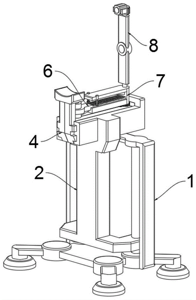
图1示出了根据本发明的实施例的中医望诊设备的示意图;FIG. 1 shows a schematic diagram of a traditional Chinese medicine inspection and diagnosis device according to an embodiment of the present invention;
图2示出了根据本发明的实施例的中医望诊设备的后侧轴视示意图;Fig. 2 shows a schematic diagram of a rear side perspective view of a traditional Chinese medicine inspection device according to an embodiment of the present invention;
图3示出了根据本发明的实施例的中医望诊设备的底座的示意图;FIG. 3 shows a schematic diagram of the base of the TCM observation and diagnosis equipment according to an embodiment of the present invention;
图4示出了根据本发明的实施例的中医望诊设备的移动架的示意图;FIG. 4 shows a schematic diagram of a mobile frame of a traditional Chinese medicine inspection equipment according to an embodiment of the present invention;
图5示出了根据本发明的实施例的中医望诊设备的移动架的拆装示意图;FIG. 5 shows a schematic diagram of disassembly and assembly of a mobile frame of a traditional Chinese medicine inspection equipment according to an embodiment of the present invention;
图6示出了根据本发明的实施例的中医望诊设备的驱动装置的安装示意图;6 shows a schematic diagram of the installation of the driving device of the traditional Chinese medicine observation and diagnosis equipment according to an embodiment of the present invention;
图7示出了根据本发明的实施例的中医望诊设备的安装台的拆分示意图;Fig. 7 shows the disassembled schematic diagram of the installation platform of the traditional Chinese medicine inspection equipment according to an embodiment of the present invention;
图8示出了根据本发明的实施例的中医望诊设备的连接臂体的示意图;FIG. 8 shows a schematic diagram of a connecting arm body of a traditional Chinese medicine observation and diagnosis device according to an embodiment of the present invention;
图9示出了根据本发明的实施例的中医望诊设备的连接臂体的拆装示意图;9 shows a schematic diagram of disassembly and assembly of the connecting arm body of the traditional Chinese medicine inspection equipment according to an embodiment of the present invention;
图10示出了根据本发明的实施例的中医望诊设备的传动装置的示意图。FIG. 10 shows a schematic diagram of a transmission device of a traditional Chinese medicine observation and diagnosis apparatus according to an embodiment of the present invention.
附图标记列表List of reference signs
1、底座;1. Base;
101、导向杆;102、调整螺杆;103、调整电机;101. Guide rod; 102. Adjusting screw; 103. Adjusting motor;
2、移动架;2. Mobile rack;
201、底板;2011、导向孔;2012、螺纹孔;202、导轨;203、限位板;201, bottom plate; 2011, guide hole; 2012, threaded hole; 202, guide rail; 203, limit plate;
3、处理器;3. Processor;
4、安装台;4. Installation table;
401、头托板;402、外滑块;401, head support plate; 402, outer slider;
5、驱动装置;5. Drive device;
501、驱动电机;502、不完全锥齿轮;503、驱动杆;5031、上锥齿轮;5032、下锥齿轮;501, drive motor; 502, incomplete bevel gear; 503, drive rod; 5031, upper bevel gear; 5032, lower bevel gear;
6、连接架;6. Connecting frame;
601、卡槽;601, card slot;
7、连接臂体;7. Connect the arm body;
701、导向槽;702、滑杆;7021、限位柱;703、弹性件;704、卡块;701, guide groove; 702, slide bar; 7021, limit post; 703, elastic piece; 704, block;
8、检测装置;8. Detection device;
801、支撑杆;802、摄像器;803、毫米波雷达;804、转动杆;801, support rod; 802, camera; 803, millimeter wave radar; 804, rotating rod;
9、传动装置;9. Transmission device;
901、传动电机;902、小齿轮;903、大齿轮。901, transmission motor; 902, pinion; 903, large gear.
具体实施方式Detailed ways
为了使得本发明的技术方案的目的、方案和优点更加清楚,下文中将结合本发明的具体实施例的附图,对本发明实施例的技术方案进行清楚、完整的描述。除非另有说明,否则本文所使用的术语具有本领域通常的含义。附图中相同的附图标记代表相同的部件。In order to make the purposes, solutions and advantages of the technical solutions of the present invention clearer, the technical solutions of the embodiments of the present invention will be clearly and completely described below with reference to the accompanying drawings of specific embodiments of the present invention. Unless otherwise specified, terms used herein have their ordinary meanings in the art. The same reference numbers in the figures represent the same parts.
实施例:请参考图1至图10:Example: Please refer to Figure 1 to Figure 10:
本发明提出了一种复合毫米波雷达的中医望诊设备,包括底座1;The present invention provides a traditional Chinese medicine observation and diagnosis equipment with a composite millimeter wave radar, comprising a
底座1的左端转动安装有一处调整螺杆102,底座1的顶端螺纹安装有一处移动架2,移动架2的顶端外侧设有一处限位板203,移动架2的顶面后端安装有一处处理器3,处理器3内设有远程传输模块,且处理器3内设有数据库,移动架2的顶端滑动安装有一处安装台4,安装台4的前侧顶端设有一处头托板401,安装台4的内部安装有一处驱动装置5,安装台4的顶端转动安装有一处连接架6;驱动装置5包括有驱动电机501和驱动杆503,驱动电机501固定安装于安装台4的内部底端,驱动杆503固定安装于连接架6的左端,且驱动杆503转动安装于安装台4上;连接架6的右端安装有一处连接臂体7;连接臂体7的左侧底端滑动安装有一处卡块704,且卡块704卡接安装于连接架6的顶端,连接臂体7的右端转动安装有一处检测装置8,连接臂体7的底端安装有一处传动装置9,检测装置8包括有支撑杆801、摄像器802、毫米波雷达803和转动杆804,摄像器802安装于支撑杆801的中段位置,毫米波雷达803安装于支撑杆801的顶端,转动杆804设于支撑杆801的底端;传动装置9包括有传动电机901、小齿轮902和大齿轮903,传动电机901固定安装于连接臂体7的右侧底端,小齿轮902安装于传动电机901的传动轴上。The left end of the base 1 is rotatably installed with an adjusting screw 102, the top end of the base 1 is threadedly installed with a moving frame 2, the outer top of the moving frame 2 is provided with a limit plate 203, and the rear end of the top surface of the moving frame 2 is installed with a treatment The processor 3 is provided with a remote transmission module, and the processor 3 is provided with a database, the top of the mobile frame 2 is slidably installed with an installation table 4, and the front top of the installation table 4 is provided with a head support plate 401, A driving device 5 is installed inside the mounting table 4, and a connecting frame 6 is installed on the top of the mounting table 4; The driving rod 503 is fixedly installed on the left end of the connecting frame 6, and the driving rod 503 is rotatably installed on the mounting table 4; the right end of the connecting frame 6 is installed with a connecting arm body 7; the left bottom end of the connecting arm body 7 is slidably installed There is a clamping block 704, and the clamping block 704 is clamped and installed on the top of the connecting frame 6, a detection device 8 is installed on the right end of the connecting arm body 7, and a transmission device 9 is installed at the bottom end of the connecting arm body 7. The
此外,根据本发明的实施例,如图3和图4所示,底座1的右端固定安装有一处导向杆101,移动架2的底端为一处底板201,底板201的右端开设有一处导向孔2011,移动架2底端底板201上的导向孔2011滑动安装于底座1右端固定安装的导向杆101上,底座1的左端固定安装有一处调整电机103,调整螺杆102的底端安装于调整电机103的传动轴上,移动架2底端的底板201左端开设有一处螺纹孔2012,移动架2底端的底板201上的螺纹孔2012螺纹安装于底座1左端转动安装的调整螺杆102上;具体作用,移动架2底端底板201上的导向孔2011滑动安装于底座1右端固定安装的导向杆101上,移动架2底端的底板201上的螺纹孔2012螺纹安装于底座1左端转动安装的调整螺杆102上,调整电机103带动调整螺杆102转动,从而使得螺纹安装于调整螺杆102上的移动架2及其上的头托板401、检测装置8根据需要进行高度的调节。In addition, according to the embodiment of the present invention, as shown in FIG. 3 and FIG. 4 , a guide rod 101 is fixedly installed at the right end of the base 1 , a bottom plate 201 is located at the bottom end of the mobile frame 2 , and a guide bar 201 is provided at the right end of the bottom plate 201 Hole 2011, the guide hole 2011 on the bottom plate 201 of the mobile frame 2 is slidably installed on the guide rod 101 fixedly installed at the right end of the base 1, the left end of the base 1 is fixedly installed with an adjusting motor 103, and the bottom end of the adjusting screw 102 is installed in the adjusting On the drive shaft of the motor 103, a threaded hole 2012 is formed on the left end of the bottom plate 201 at the bottom end of the moving frame 2, and the threaded hole 2012 on the bottom plate 201 at the bottom end of the moving frame 2 is threadedly installed on the adjusting screw 102 installed on the left end of the base 1; the specific function , the guide hole 2011 on the bottom plate 201 of the mobile frame 2 is slidably installed on the guide rod 101 fixedly installed on the right end of the base 1, and the threaded hole 2012 on the bottom plate 201 of the mobile frame 2 is threadedly installed on the left end of the base 1. 102, the adjusting
此外,根据本发明的实施例,如图5至图8所示,安装台4的左右侧各设有两处外滑块402,移动架2的顶端设有一处导轨202,且安装台4左右侧的外滑块402滑动安装于移动架2顶端设有的导轨202上,连接臂体7的顶端开设有一处导向槽701,连接架6的右端滑动安装于连接臂体7的顶端开设有的导向槽701上,连接架6的顶面呈阵列式等距开设有卡槽601,连接臂体7上安装的卡块704底端为上窄下宽的对称式斜体结构,且连接臂体7上的卡块704卡接安装于连接架6顶面的卡槽601上,连接臂体7的底端滑动安装的卡块704两端各开设有一处滑孔,连接臂体7的左侧底面固定安装有两处滑杆702,滑杆702的底端设有一处限位柱7021,且连接臂体7底端卡块704两端的滑孔分别滑动安装于连接臂体7左侧底面固定安装的滑杆702上,连接臂体7左侧底面的两处滑杆702上分别套接安装有一处弹性件703,且弹性件703的底端与卡块704的顶端相接触;具体作用,安装台4左右侧的外滑块402滑动安装于移动架2顶端设有的导轨202上,使得使用者根据需要便于调节安装台4上头托板401的伸出位置,连接架6的右端滑动安装于连接臂体7的顶端开设有的导向槽701上,连接臂体7底端卡块704两端的滑孔分别滑动安装于连接臂体7左侧底面固定安装的滑杆702上,配合滑杆702上套接安装的弹性件703,向外拉动连接架6,从而使得连接臂体7上的卡块704卡接安装于连接架6顶面不同的卡槽601上,从而使得检测装置8旋转臂的半径便于调整,提高了装置的可调节性能。In addition, according to the embodiment of the present invention, as shown in FIGS. 5 to 8 , the left and right sides of the installation table 4 are provided with two outer sliders 402 respectively, the top of the moving
此外,根据本发明的实施例,如图9所示,驱动装置5还包括有不完全锥齿轮502、上锥齿轮5031和下锥齿轮5032,不完全锥齿轮502安装于驱动电机501的传动轴上,上锥齿轮5031和下锥齿轮5032相对安装于驱动杆503上,且上锥齿轮5031和下锥齿轮5032分别与不完全锥齿轮502啮合传动连接;具体作用,使用者将下巴贴于头托板401上,驱动电机501带动不完全锥齿轮502转动,当不完全锥齿轮502与驱动杆503上的上锥齿轮5031啮合传动连接时,不完全锥齿轮502与驱动杆503上的下锥齿轮5032不啮合,从而带动驱动杆503及其上的检测装置8绕着使用者的头部转动半圈,然后不完全锥齿轮502与驱动杆503上的下锥齿轮5032啮合传动连接,不完全锥齿轮502与驱动杆503上的上锥齿轮5031不啮合,从而使得驱动杆503及其上的检测装置8绕着使用者的头部向相反方向转动半圈,配合检测装置8上的摄像器802和毫米波雷达803,以使得摄像器802能够对患者的半身以上进行不同角度的拍摄上传并通过处理器3进行对比检测,毫米波雷达803对使用者的呼吸频率及心跳频率,提高了本装置对使用者望诊的检测效果,如图10所示,检测装置8上的转动杆804转动安装于连接臂体7的右端,大齿轮903固定安装于检测装置8上的转动杆804底端,且小齿轮902与转动杆804底端的大齿轮903啮合传动连接;具体作用,小齿轮902与转动杆804底端的大齿轮903啮合传动连接,传动电机901带动小齿轮902转动,从而带动大齿轮903及其上的检测装置8进行转动,配合摄像器802及处理器3,能够控制本装置的检测装置8根据使用者的位置进行转动,使毫米波雷达803间隔性的检测使用者的呼吸频率和心跳频率等身体特征。In addition, according to the embodiment of the present invention, as shown in FIG. 9 , the driving
本实施例的具体使用方式与作用:本发明中,移动架2底端底板201上的导向孔2011滑动安装于底座1右端固定安装的导向杆101上,移动架2底端的底板201上的螺纹孔2012螺纹安装于底座1左端转动安装的调整螺杆102上,调整电机103带动调整螺杆102转动,从而使得螺纹安装于调整螺杆102上的移动架2及其上的头托板401、检测装置8根据需要进行高度的调节;安装台4左右侧的外滑块402滑动安装于移动架2顶端设有的导轨202上,使得使用者根据需要便于调节安装台4上头托板401的伸出位置,连接架6的右端滑动安装于连接臂体7的顶端开设有的导向槽701上,连接臂体7底端卡块704两端的滑孔分别滑动安装于连接臂体7左侧底面固定安装的滑杆702上,配合滑杆702上套接安装的弹性件703,向外拉动连接架6,从而使得连接臂体7上的卡块704卡接安装于连接架6顶面不同的卡槽601上,从而使得检测装置8旋转臂的半径便于调整,提高了装置的可调节性能;使用者将下巴贴于头托板401上,驱动电机501带动不完全锥齿轮502转动,当不完全锥齿轮502与驱动杆503上的上锥齿轮5031啮合传动连接时,不完全锥齿轮502与驱动杆503上的下锥齿轮5032不啮合,从而带动驱动杆503及其上的检测装置8绕着使用者的头部转动半圈,然后不完全锥齿轮502与驱动杆503上的下锥齿轮5032啮合传动连接,不完全锥齿轮502与驱动杆503上的上锥齿轮5031不啮合,从而使得驱动杆503及其上的检测装置8绕着使用者的头部向相反方向转动半圈,配合检测装置8上的摄像器802和毫米波雷达803,以使得摄像器802能够对患者的半身以上进行不同角度的拍摄上传并通过处理器3进行对比检测,毫米波雷达803对使用者的呼吸频率及心跳频率,提高了本装置对使用者望诊的检测效果;小齿轮902与转动杆804底端的大齿轮903啮合传动连接,传动电机901带动小齿轮902转动,从而带动大齿轮903及其上的检测装置8进行转动,配合摄像器802及处理器3,能够控制本装置的检测装置8根据使用者的位置进行转动,使毫米波雷达803间隔性的检测使用者的呼吸频率和心跳频率等身体特征。The specific usage and function of this embodiment: In the present invention, the
最后,需要说明的是,本发明在描述各个构件的位置及其之间的配合关系等时,通常会以一个/一对构件举例而言,然而本领域技术人员应该理解的是,这样的位置、配合关系等,同样适用于其他构件/其他成对的构件。Finally, it should be noted that when describing the position of each component and the matching relationship between them, the present invention usually takes one/a pair of components as an example. However, those skilled in the art should understand that such a position , mating relationship, etc., the same applies to other components / other paired components.
以上所述仅是本发明的示范性实施方式,而非用于限制本发明的保护范围,本发明的保护范围由所附的权利要求确定。The above descriptions are only exemplary embodiments of the present invention, and are not intended to limit the protection scope of the present invention, which is determined by the appended claims.
Claims (10)
Priority Applications (3)
| Application Number | Priority Date | Filing Date | Title |
|---|---|---|---|
| CN202210432549.2A CN114732367A (en) | 2022-04-24 | 2022-04-24 | Traditional Chinese medicine inspection diagnosis equipment of composite millimeter wave radar |
| DE202023101817.3U DE202023101817U1 (en) | 2022-04-24 | 2023-04-12 | Traditional Chinese medicine observation device with connected millimeter wave radar |
| US18/136,890 US12390300B2 (en) | 2022-04-24 | 2023-04-20 | Traditional chinese medicine inspection device of composite millimeter-wave radar |
Applications Claiming Priority (1)
| Application Number | Priority Date | Filing Date | Title |
|---|---|---|---|
| CN202210432549.2A CN114732367A (en) | 2022-04-24 | 2022-04-24 | Traditional Chinese medicine inspection diagnosis equipment of composite millimeter wave radar |
Publications (1)
| Publication Number | Publication Date |
|---|---|
| CN114732367A true CN114732367A (en) | 2022-07-12 |
Family
ID=82282740
Family Applications (1)
| Application Number | Title | Priority Date | Filing Date |
|---|---|---|---|
| CN202210432549.2A Pending CN114732367A (en) | 2022-04-24 | 2022-04-24 | Traditional Chinese medicine inspection diagnosis equipment of composite millimeter wave radar |
Country Status (3)
| Country | Link |
|---|---|
| US (1) | US12390300B2 (en) |
| CN (1) | CN114732367A (en) |
| DE (1) | DE202023101817U1 (en) |
Families Citing this family (1)
| Publication number | Priority date | Publication date | Assignee | Title |
|---|---|---|---|---|
| CN118896224A (en) * | 2024-10-08 | 2024-11-05 | 中国人民解放军海军军医大学 | A genetic diversity analysis and detection device using genetic elements |
Citations (12)
| Publication number | Priority date | Publication date | Assignee | Title |
|---|---|---|---|---|
| CN201082167Y (en) * | 2007-09-17 | 2008-07-09 | 刘衍民 | All-directional rotating camera shooting device above operating table |
| CN107713984A (en) * | 2017-02-07 | 2018-02-23 | 王俊 | Facial paralysis objective evaluation method and its system |
| CN108420409A (en) * | 2018-05-17 | 2018-08-21 | 安徽昱康智能科技有限公司 | A kind of facial information harvester and its physical-examination machine |
| CN109620421A (en) * | 2019-02-15 | 2019-04-16 | 郑州大学 | Tongue, pulse diagnostic information acquisition bracket |
| CN210899316U (en) * | 2019-12-24 | 2020-06-30 | 苏州艾儿维斯智能科技有限公司 | Monitoring device for campus safety |
| CN211609754U (en) * | 2020-02-15 | 2020-10-02 | 邴婧毓 | A traditional Chinese medicine tongue diagnosis and treatment instrument |
| CN212700191U (en) * | 2020-03-25 | 2021-03-16 | 江苏南源消防工程有限公司 | Fire-fighting water spraying equipment |
| CN213216974U (en) * | 2020-05-25 | 2021-05-18 | 浙江海洋大学 | Vital sign monitoring device |
| CN213658960U (en) * | 2020-11-20 | 2021-07-09 | 王林 | Emission preceding stage power testing arrangement of radar detection maintenance |
| CN114041767A (en) * | 2021-10-11 | 2022-02-15 | 宁波春建电子科技有限公司 | Heart rate detection method based on depth camera and millimeter wave radar |
| CN216060499U (en) * | 2021-06-29 | 2022-03-18 | 深圳市万佳安智能科技有限公司 | Vital sign monitoring camera system based on millimeter wave radar |
| CN217548017U (en) * | 2022-04-24 | 2022-10-11 | 中国中医科学院中医药信息研究所 | Traditional Chinese medicine inspection diagnosis equipment of composite millimeter wave radar |
Family Cites Families (29)
| Publication number | Priority date | Publication date | Assignee | Title |
|---|---|---|---|---|
| US2518288A (en) * | 1946-02-06 | 1950-08-08 | Suzanne Rosalie Coutard | Steerable motion-picture camera stand |
| US2661672A (en) * | 1950-06-15 | 1953-12-08 | Jerry B Fairbanks | Tripod mechanism |
| DE3434386A1 (en) * | 1984-09-19 | 1986-03-27 | Sachtler GmbH Filmtechnische Geräte, 8046 Garching | FILM OR TELEVISION CAMERA TRIPOD |
| USD361587S (en) * | 1994-05-10 | 1995-08-22 | Leonard Studio Equipment, Inc. | Combined camera dolly and support column therefor |
| US5730450A (en) * | 1995-12-26 | 1998-03-24 | Leonard Studio Equipment, Inc. | Push/steering bar for a camera pedestal |
| US6439515B1 (en) * | 2000-10-10 | 2002-08-27 | Adam Daniel Powers | Video camera support device |
| US6443543B1 (en) * | 2001-04-06 | 2002-09-03 | Wayne Chiang | Mobile personal computer |
| US20070296816A1 (en) * | 2006-06-27 | 2007-12-27 | Jess Rubio | System and method for split screen image of drawing |
| CA2653462A1 (en) * | 2008-02-08 | 2009-08-08 | Dennis Woods | Camera dolly |
| US8142019B2 (en) * | 2008-06-23 | 2012-03-27 | Charles Hernandez | Dolly and track system |
| USD670752S1 (en) * | 2008-09-18 | 2012-11-13 | Edward Barber | Portable camera mount |
| US8142083B2 (en) * | 2008-11-14 | 2012-03-27 | Brown Garrett W | Extendable camera support and stabilization apparatus |
| CN101929838B (en) * | 2009-06-26 | 2012-09-19 | 鸿富锦精密工业(深圳)有限公司 | Bracket and image measuring device using the same |
| US8943779B2 (en) * | 2011-04-28 | 2015-02-03 | Yuyama Mfg. Co., Ltd. | Medicine inspection device, and medicine packaging device |
| KR102223436B1 (en) * | 2012-10-03 | 2021-03-05 | 가부시키가이샤 유야마 세이사쿠쇼 | Medicinal agent inspection system, winding device, feed device, and holder |
| WO2015106207A1 (en) * | 2014-01-13 | 2015-07-16 | Endochoice, Inc. | Compact monitor stand |
| EP2946759A1 (en) * | 2014-05-19 | 2015-11-25 | The University of Dundee | Medical equipment support system fitted between floor and ceiling |
| US20230065062A1 (en) * | 2016-03-24 | 2023-03-02 | Archi Enterprises Inc. | Modular utility system |
| CN107124899B (en) * | 2016-07-15 | 2019-07-05 | 深圳市大疆创新科技有限公司 | Movable fixture, follow shot equipment, movable fixture control system and method |
| US10841473B2 (en) * | 2016-12-19 | 2020-11-17 | Foto Master Ltd. | Photo terminal stand system |
| US20240406415A1 (en) * | 2018-02-20 | 2024-12-05 | Arlo Technologies, Inc. | Multi-sensor motion detection |
| EP3917440B1 (en) * | 2019-01-31 | 2024-01-31 | American Sterilizer Company | Modular adapters for medical device support system |
| CN116635806A (en) * | 2020-11-20 | 2023-08-22 | Abb瑞士股份有限公司 | Method for manipulating vehicle by mobile robot, control system and mobile robot |
| US20240029237A1 (en) * | 2020-12-03 | 2024-01-25 | Ziuz Holding B.V. | Inspecting medicine objects based on hyperspectral imaging |
| EP4297628A4 (en) * | 2021-02-26 | 2024-11-13 | Saltzburg, Harris Rand | MULTIFUNCTIONAL INTRAORAL IMAGING SYSTEM AND RELATED METHODS |
| US20230240793A1 (en) * | 2022-02-02 | 2023-08-03 | Mako Surgical Corp. | Quick-Connect Mounting System For Surgical Components |
| US12386027B2 (en) * | 2023-02-13 | 2025-08-12 | GM Global Technology Operations LLC | Radar interference mitigation by monitoring of channels and switching to interference-free channel |
| WO2025074227A1 (en) * | 2023-10-02 | 2025-04-10 | Trackman A/S | System and method for enhanced tracking, and a club for use in the method |
| US12194645B1 (en) * | 2024-02-27 | 2025-01-14 | Foto Master Ltd | Integrated drawing system and method |
-
2022
- 2022-04-24 CN CN202210432549.2A patent/CN114732367A/en active Pending
-
2023
- 2023-04-12 DE DE202023101817.3U patent/DE202023101817U1/en active Active
- 2023-04-20 US US18/136,890 patent/US12390300B2/en active Active
Patent Citations (12)
| Publication number | Priority date | Publication date | Assignee | Title |
|---|---|---|---|---|
| CN201082167Y (en) * | 2007-09-17 | 2008-07-09 | 刘衍民 | All-directional rotating camera shooting device above operating table |
| CN107713984A (en) * | 2017-02-07 | 2018-02-23 | 王俊 | Facial paralysis objective evaluation method and its system |
| CN108420409A (en) * | 2018-05-17 | 2018-08-21 | 安徽昱康智能科技有限公司 | A kind of facial information harvester and its physical-examination machine |
| CN109620421A (en) * | 2019-02-15 | 2019-04-16 | 郑州大学 | Tongue, pulse diagnostic information acquisition bracket |
| CN210899316U (en) * | 2019-12-24 | 2020-06-30 | 苏州艾儿维斯智能科技有限公司 | Monitoring device for campus safety |
| CN211609754U (en) * | 2020-02-15 | 2020-10-02 | 邴婧毓 | A traditional Chinese medicine tongue diagnosis and treatment instrument |
| CN212700191U (en) * | 2020-03-25 | 2021-03-16 | 江苏南源消防工程有限公司 | Fire-fighting water spraying equipment |
| CN213216974U (en) * | 2020-05-25 | 2021-05-18 | 浙江海洋大学 | Vital sign monitoring device |
| CN213658960U (en) * | 2020-11-20 | 2021-07-09 | 王林 | Emission preceding stage power testing arrangement of radar detection maintenance |
| CN216060499U (en) * | 2021-06-29 | 2022-03-18 | 深圳市万佳安智能科技有限公司 | Vital sign monitoring camera system based on millimeter wave radar |
| CN114041767A (en) * | 2021-10-11 | 2022-02-15 | 宁波春建电子科技有限公司 | Heart rate detection method based on depth camera and millimeter wave radar |
| CN217548017U (en) * | 2022-04-24 | 2022-10-11 | 中国中医科学院中医药信息研究所 | Traditional Chinese medicine inspection diagnosis equipment of composite millimeter wave radar |
Also Published As
| Publication number | Publication date |
|---|---|
| DE202023101817U1 (en) | 2023-05-11 |
| US12390300B2 (en) | 2025-08-19 |
| US20230338109A1 (en) | 2023-10-26 |
Similar Documents
| Publication | Publication Date | Title |
|---|---|---|
| CN114732367A (en) | Traditional Chinese medicine inspection diagnosis equipment of composite millimeter wave radar | |
| CN105943130A (en) | Puncture frame | |
| CN217548017U (en) | Traditional Chinese medicine inspection diagnosis equipment of composite millimeter wave radar | |
| CN204562192U (en) | Digitized X-ray image documentation equipment | |
| CN119366943B (en) | Medical image acquisition device | |
| CN205964021U (en) | Vein formation of image display instrument | |
| CN113267864A (en) | Angle fine-tuning mechanism for optical element | |
| CN219021433U (en) | Accurate puncture positioner of transpedicular for backbone operation | |
| CN115728956A (en) | Breast cancer image diagnosis equipment | |
| CN115363721A (en) | A visual radial artery puncture device | |
| CN115308912A (en) | Auxiliary film viewing device for medical image viewing | |
| CN115429322A (en) | TCCS probe fixing device | |
| CN223416246U (en) | An ultrasonic automatic scanning medical imaging device | |
| CN220546278U (en) | Image diagnosis host equipment | |
| CN109481035B (en) | Wrist fixing device for pulse-taking instrument | |
| CN221897531U (en) | Image acquisition processing device | |
| CN220158660U (en) | Scanning system with adjustable medical image | |
| CN218268271U (en) | an imaging device | |
| CN112155592A (en) | Intelligent computer image processing device convenient to move | |
| CN219921082U (en) | Infant chest radiography auxiliary device of image radiology department | |
| CN111407372B (en) | A positioning puncture guide device | |
| CN220930717U (en) | Novel adjustable camera fixed bolster | |
| CN215078881U (en) | Transcranial Doppler convenient to operate | |
| CN215495520U (en) | Fingering recognition device and piano teaching system | |
| CN221804253U (en) | Magnetic resonance receiving coil capable of being automatically adjusted |
Legal Events
| Date | Code | Title | Description |
|---|---|---|---|
| PB01 | Publication | ||
| PB01 | Publication | ||
| SE01 | Entry into force of request for substantive examination | ||
| SE01 | Entry into force of request for substantive examination |